WO2013061734A1 - 立体表示装置 - Google Patents
立体表示装置 Download PDFInfo
- Publication number
- WO2013061734A1 WO2013061734A1 PCT/JP2012/075547 JP2012075547W WO2013061734A1 WO 2013061734 A1 WO2013061734 A1 WO 2013061734A1 JP 2012075547 W JP2012075547 W JP 2012075547W WO 2013061734 A1 WO2013061734 A1 WO 2013061734A1
- Authority
- WO
- WIPO (PCT)
- Prior art keywords
- liquid crystal
- display panel
- display device
- lens
- stereoscopic
- Prior art date
- Legal status (The legal status is an assumption and is not a legal conclusion. Google has not performed a legal analysis and makes no representation as to the accuracy of the status listed.)
- Ceased
Links
Images




Classifications
-
- H—ELECTRICITY
- H04—ELECTRIC COMMUNICATION TECHNIQUE
- H04N—PICTORIAL COMMUNICATION, e.g. TELEVISION
- H04N13/00—Stereoscopic video systems; Multi-view video systems; Details thereof
- H04N13/30—Image reproducers
- H04N13/349—Multi-view displays for displaying three or more geometrical viewpoints without viewer tracking
- H04N13/351—Multi-view displays for displaying three or more geometrical viewpoints without viewer tracking for displaying simultaneously
-
- G—PHYSICS
- G02—OPTICS
- G02B—OPTICAL ELEMENTS, SYSTEMS OR APPARATUS
- G02B30/00—Optical systems or apparatus for producing three-dimensional [3D] effects, e.g. stereoscopic images
- G02B30/20—Optical systems or apparatus for producing three-dimensional [3D] effects, e.g. stereoscopic images by providing first and second parallax images to an observer's left and right eyes
- G02B30/26—Optical systems or apparatus for producing three-dimensional [3D] effects, e.g. stereoscopic images by providing first and second parallax images to an observer's left and right eyes of the autostereoscopic type
- G02B30/27—Optical systems or apparatus for producing three-dimensional [3D] effects, e.g. stereoscopic images by providing first and second parallax images to an observer's left and right eyes of the autostereoscopic type involving lenticular arrays
-
- G—PHYSICS
- G02—OPTICS
- G02B—OPTICAL ELEMENTS, SYSTEMS OR APPARATUS
- G02B30/00—Optical systems or apparatus for producing three-dimensional [3D] effects, e.g. stereoscopic images
- G02B30/20—Optical systems or apparatus for producing three-dimensional [3D] effects, e.g. stereoscopic images by providing first and second parallax images to an observer's left and right eyes
- G02B30/26—Optical systems or apparatus for producing three-dimensional [3D] effects, e.g. stereoscopic images by providing first and second parallax images to an observer's left and right eyes of the autostereoscopic type
- G02B30/27—Optical systems or apparatus for producing three-dimensional [3D] effects, e.g. stereoscopic images by providing first and second parallax images to an observer's left and right eyes of the autostereoscopic type involving lenticular arrays
- G02B30/28—Optical systems or apparatus for producing three-dimensional [3D] effects, e.g. stereoscopic images by providing first and second parallax images to an observer's left and right eyes of the autostereoscopic type involving lenticular arrays involving active lenticular arrays
-
- G—PHYSICS
- G02—OPTICS
- G02F—OPTICAL DEVICES OR ARRANGEMENTS FOR THE CONTROL OF LIGHT BY MODIFICATION OF THE OPTICAL PROPERTIES OF THE MEDIA OF THE ELEMENTS INVOLVED THEREIN; NON-LINEAR OPTICS; FREQUENCY-CHANGING OF LIGHT; OPTICAL LOGIC ELEMENTS; OPTICAL ANALOGUE/DIGITAL CONVERTERS
- G02F1/00—Devices or arrangements for the control of the intensity, colour, phase, polarisation or direction of light arriving from an independent light source, e.g. switching, gating or modulating; Non-linear optics
- G02F1/01—Devices or arrangements for the control of the intensity, colour, phase, polarisation or direction of light arriving from an independent light source, e.g. switching, gating or modulating; Non-linear optics for the control of the intensity, phase, polarisation or colour
- G02F1/13—Devices or arrangements for the control of the intensity, colour, phase, polarisation or direction of light arriving from an independent light source, e.g. switching, gating or modulating; Non-linear optics for the control of the intensity, phase, polarisation or colour based on liquid crystals, e.g. single liquid crystal display cells
- G02F1/133—Constructional arrangements; Operation of liquid crystal cells; Circuit arrangements
- G02F1/1333—Constructional arrangements; Manufacturing methods
- G02F1/1343—Electrodes
- G02F1/134309—Electrodes characterised by their geometrical arrangement
-
- G—PHYSICS
- G02—OPTICS
- G02F—OPTICAL DEVICES OR ARRANGEMENTS FOR THE CONTROL OF LIGHT BY MODIFICATION OF THE OPTICAL PROPERTIES OF THE MEDIA OF THE ELEMENTS INVOLVED THEREIN; NON-LINEAR OPTICS; FREQUENCY-CHANGING OF LIGHT; OPTICAL LOGIC ELEMENTS; OPTICAL ANALOGUE/DIGITAL CONVERTERS
- G02F1/00—Devices or arrangements for the control of the intensity, colour, phase, polarisation or direction of light arriving from an independent light source, e.g. switching, gating or modulating; Non-linear optics
- G02F1/01—Devices or arrangements for the control of the intensity, colour, phase, polarisation or direction of light arriving from an independent light source, e.g. switching, gating or modulating; Non-linear optics for the control of the intensity, phase, polarisation or colour
- G02F1/13—Devices or arrangements for the control of the intensity, colour, phase, polarisation or direction of light arriving from an independent light source, e.g. switching, gating or modulating; Non-linear optics for the control of the intensity, phase, polarisation or colour based on liquid crystals, e.g. single liquid crystal display cells
- G02F1/133—Constructional arrangements; Operation of liquid crystal cells; Circuit arrangements
- G02F1/1333—Constructional arrangements; Manufacturing methods
- G02F1/1347—Arrangement of liquid crystal layers or cells in which the final condition of one light beam is achieved by the addition of the effects of two or more layers or cells
- G02F1/13471—Arrangement of liquid crystal layers or cells in which the final condition of one light beam is achieved by the addition of the effects of two or more layers or cells in which all the liquid crystal cells or layers remain transparent, e.g. FLC, ECB, DAP, HAN, TN, STN, SBE-LC cells
-
- G—PHYSICS
- G03—PHOTOGRAPHY; CINEMATOGRAPHY; ANALOGOUS TECHNIQUES USING WAVES OTHER THAN OPTICAL WAVES; ELECTROGRAPHY; HOLOGRAPHY
- G03B—APPARATUS OR ARRANGEMENTS FOR TAKING PHOTOGRAPHS OR FOR PROJECTING OR VIEWING THEM; APPARATUS OR ARRANGEMENTS EMPLOYING ANALOGOUS TECHNIQUES USING WAVES OTHER THAN OPTICAL WAVES; ACCESSORIES THEREFOR
- G03B35/00—Stereoscopic photography
- G03B35/18—Stereoscopic photography by simultaneous viewing
- G03B35/24—Stereoscopic photography by simultaneous viewing using apertured or refractive resolving means on screens or between screen and eye
-
- G—PHYSICS
- G09—EDUCATION; CRYPTOGRAPHY; DISPLAY; ADVERTISING; SEALS
- G09G—ARRANGEMENTS OR CIRCUITS FOR CONTROL OF INDICATING DEVICES USING STATIC MEANS TO PRESENT VARIABLE INFORMATION
- G09G3/00—Control arrangements or circuits, of interest only in connection with visual indicators other than cathode-ray tubes
- G09G3/20—Control arrangements or circuits, of interest only in connection with visual indicators other than cathode-ray tubes for presentation of an assembly of a number of characters, e.g. a page, by composing the assembly by combination of individual elements arranged in a matrix no fixed position being assigned to or needed to be assigned to the individual characters or partial characters
- G09G3/34—Control arrangements or circuits, of interest only in connection with visual indicators other than cathode-ray tubes for presentation of an assembly of a number of characters, e.g. a page, by composing the assembly by combination of individual elements arranged in a matrix no fixed position being assigned to or needed to be assigned to the individual characters or partial characters by control of light from an independent source
- G09G3/36—Control arrangements or circuits, of interest only in connection with visual indicators other than cathode-ray tubes for presentation of an assembly of a number of characters, e.g. a page, by composing the assembly by combination of individual elements arranged in a matrix no fixed position being assigned to or needed to be assigned to the individual characters or partial characters by control of light from an independent source using liquid crystals
- G09G3/3607—Control arrangements or circuits, of interest only in connection with visual indicators other than cathode-ray tubes for presentation of an assembly of a number of characters, e.g. a page, by composing the assembly by combination of individual elements arranged in a matrix no fixed position being assigned to or needed to be assigned to the individual characters or partial characters by control of light from an independent source using liquid crystals for displaying colours or for displaying grey scales with a specific pixel layout, e.g. using sub-pixels
-
- G—PHYSICS
- G09—EDUCATION; CRYPTOGRAPHY; DISPLAY; ADVERTISING; SEALS
- G09G—ARRANGEMENTS OR CIRCUITS FOR CONTROL OF INDICATING DEVICES USING STATIC MEANS TO PRESENT VARIABLE INFORMATION
- G09G3/00—Control arrangements or circuits, of interest only in connection with visual indicators other than cathode-ray tubes
- G09G3/20—Control arrangements or circuits, of interest only in connection with visual indicators other than cathode-ray tubes for presentation of an assembly of a number of characters, e.g. a page, by composing the assembly by combination of individual elements arranged in a matrix no fixed position being assigned to or needed to be assigned to the individual characters or partial characters
- G09G3/34—Control arrangements or circuits, of interest only in connection with visual indicators other than cathode-ray tubes for presentation of an assembly of a number of characters, e.g. a page, by composing the assembly by combination of individual elements arranged in a matrix no fixed position being assigned to or needed to be assigned to the individual characters or partial characters by control of light from an independent source
- G09G3/36—Control arrangements or circuits, of interest only in connection with visual indicators other than cathode-ray tubes for presentation of an assembly of a number of characters, e.g. a page, by composing the assembly by combination of individual elements arranged in a matrix no fixed position being assigned to or needed to be assigned to the individual characters or partial characters by control of light from an independent source using liquid crystals
- G09G3/3611—Control of matrices with row and column drivers
- G09G3/3648—Control of matrices with row and column drivers using an active matrix
-
- H—ELECTRICITY
- H04—ELECTRIC COMMUNICATION TECHNIQUE
- H04N—PICTORIAL COMMUNICATION, e.g. TELEVISION
- H04N13/00—Stereoscopic video systems; Multi-view video systems; Details thereof
- H04N13/10—Processing, recording or transmission of stereoscopic or multi-view image signals
- H04N13/106—Processing image signals
- H04N13/144—Processing image signals for flicker reduction
-
- H—ELECTRICITY
- H04—ELECTRIC COMMUNICATION TECHNIQUE
- H04N—PICTORIAL COMMUNICATION, e.g. TELEVISION
- H04N13/00—Stereoscopic video systems; Multi-view video systems; Details thereof
- H04N13/30—Image reproducers
- H04N13/302—Image reproducers for viewing without the aid of special glasses, i.e. using autostereoscopic displays
- H04N13/305—Image reproducers for viewing without the aid of special glasses, i.e. using autostereoscopic displays using lenticular lenses, e.g. arrangements of cylindrical lenses
-
- H—ELECTRICITY
- H04—ELECTRIC COMMUNICATION TECHNIQUE
- H04N—PICTORIAL COMMUNICATION, e.g. TELEVISION
- H04N13/00—Stereoscopic video systems; Multi-view video systems; Details thereof
- H04N13/30—Image reproducers
- H04N13/366—Image reproducers using viewer tracking
-
- H—ELECTRICITY
- H04—ELECTRIC COMMUNICATION TECHNIQUE
- H04N—PICTORIAL COMMUNICATION, e.g. TELEVISION
- H04N13/00—Stereoscopic video systems; Multi-view video systems; Details thereof
- H04N13/30—Image reproducers
- H04N13/398—Synchronisation thereof; Control thereof
-
- G—PHYSICS
- G02—OPTICS
- G02F—OPTICAL DEVICES OR ARRANGEMENTS FOR THE CONTROL OF LIGHT BY MODIFICATION OF THE OPTICAL PROPERTIES OF THE MEDIA OF THE ELEMENTS INVOLVED THEREIN; NON-LINEAR OPTICS; FREQUENCY-CHANGING OF LIGHT; OPTICAL LOGIC ELEMENTS; OPTICAL ANALOGUE/DIGITAL CONVERTERS
- G02F1/00—Devices or arrangements for the control of the intensity, colour, phase, polarisation or direction of light arriving from an independent light source, e.g. switching, gating or modulating; Non-linear optics
- G02F1/29—Devices or arrangements for the control of the intensity, colour, phase, polarisation or direction of light arriving from an independent light source, e.g. switching, gating or modulating; Non-linear optics for the control of the position or the direction of light beams, i.e. deflection
- G02F1/294—Variable focal length devices
-
- G—PHYSICS
- G02—OPTICS
- G02F—OPTICAL DEVICES OR ARRANGEMENTS FOR THE CONTROL OF LIGHT BY MODIFICATION OF THE OPTICAL PROPERTIES OF THE MEDIA OF THE ELEMENTS INVOLVED THEREIN; NON-LINEAR OPTICS; FREQUENCY-CHANGING OF LIGHT; OPTICAL LOGIC ELEMENTS; OPTICAL ANALOGUE/DIGITAL CONVERTERS
- G02F2201/00—Constructional arrangements not provided for in groups G02F1/00 - G02F7/00
- G02F2201/18—Constructional arrangements not provided for in groups G02F1/00 - G02F7/00 parallel
-
- G—PHYSICS
- G02—OPTICS
- G02F—OPTICAL DEVICES OR ARRANGEMENTS FOR THE CONTROL OF LIGHT BY MODIFICATION OF THE OPTICAL PROPERTIES OF THE MEDIA OF THE ELEMENTS INVOLVED THEREIN; NON-LINEAR OPTICS; FREQUENCY-CHANGING OF LIGHT; OPTICAL LOGIC ELEMENTS; OPTICAL ANALOGUE/DIGITAL CONVERTERS
- G02F2203/00—Function characteristic
- G02F2203/18—Function characteristic adaptive optics, e.g. wavefront correction
-
- G—PHYSICS
- G02—OPTICS
- G02F—OPTICAL DEVICES OR ARRANGEMENTS FOR THE CONTROL OF LIGHT BY MODIFICATION OF THE OPTICAL PROPERTIES OF THE MEDIA OF THE ELEMENTS INVOLVED THEREIN; NON-LINEAR OPTICS; FREQUENCY-CHANGING OF LIGHT; OPTICAL LOGIC ELEMENTS; OPTICAL ANALOGUE/DIGITAL CONVERTERS
- G02F2203/00—Function characteristic
- G02F2203/28—Function characteristic focussing or defocussing
-
- G—PHYSICS
- G02—OPTICS
- G02F—OPTICAL DEVICES OR ARRANGEMENTS FOR THE CONTROL OF LIGHT BY MODIFICATION OF THE OPTICAL PROPERTIES OF THE MEDIA OF THE ELEMENTS INVOLVED THEREIN; NON-LINEAR OPTICS; FREQUENCY-CHANGING OF LIGHT; OPTICAL LOGIC ELEMENTS; OPTICAL ANALOGUE/DIGITAL CONVERTERS
- G02F2203/00—Function characteristic
- G02F2203/62—Switchable arrangements whereby the element being usually not switchable
-
- G—PHYSICS
- G09—EDUCATION; CRYPTOGRAPHY; DISPLAY; ADVERTISING; SEALS
- G09G—ARRANGEMENTS OR CIRCUITS FOR CONTROL OF INDICATING DEVICES USING STATIC MEANS TO PRESENT VARIABLE INFORMATION
- G09G2300/00—Aspects of the constitution of display devices
- G09G2300/08—Active matrix structure, i.e. with use of active elements, inclusive of non-linear two terminal elements, in the pixels together with light emitting or modulating elements
-
- G—PHYSICS
- G09—EDUCATION; CRYPTOGRAPHY; DISPLAY; ADVERTISING; SEALS
- G09G—ARRANGEMENTS OR CIRCUITS FOR CONTROL OF INDICATING DEVICES USING STATIC MEANS TO PRESENT VARIABLE INFORMATION
- G09G2320/00—Control of display operating conditions
- G09G2320/02—Improving the quality of display appearance
- G09G2320/028—Improving the quality of display appearance by changing the viewing angle properties, e.g. widening the viewing angle, adapting the viewing angle to the view direction
-
- G—PHYSICS
- G09—EDUCATION; CRYPTOGRAPHY; DISPLAY; ADVERTISING; SEALS
- G09G—ARRANGEMENTS OR CIRCUITS FOR CONTROL OF INDICATING DEVICES USING STATIC MEANS TO PRESENT VARIABLE INFORMATION
- G09G2320/00—Control of display operating conditions
- G09G2320/06—Adjustment of display parameters
- G09G2320/068—Adjustment of display parameters for control of viewing angle adjustment
-
- G—PHYSICS
- G09—EDUCATION; CRYPTOGRAPHY; DISPLAY; ADVERTISING; SEALS
- G09G—ARRANGEMENTS OR CIRCUITS FOR CONTROL OF INDICATING DEVICES USING STATIC MEANS TO PRESENT VARIABLE INFORMATION
- G09G2354/00—Aspects of interface with display user
Definitions
- the present invention relates to a stereoscopic display device, and more particularly to a stereoscopic display device capable of autostereoscopic viewing.
- Japanese Patent Laid-Open No. 2007-336002 discloses a so-called multi-view stereoscopic display device.
- the principle of the stereoscopic display device described in Japanese Patent Application Laid-Open No. 2007-336002 is as follows.
- the stereoscopic display device regularly displays images taken from multiple directions on the display surface.
- a plurality of lenticular lenses are arranged at regular intervals on the front surface of the display surface.
- Each of the images photographed from multiple directions is separated by the lenticular lens.
- Japanese Unexamined Patent Application Publication No. 2010-282090 discloses a stereoscopic display device including a display panel and a variable lens array element.
- the variable lens array element electrodes are provided at least in the horizontal direction for each arrangement position of the sub-pixels of the display panel in the horizontal direction, and the shape of the cylindrical lens is changed in units of sub-pixels.
- Japanese Unexamined Patent Application Publication No. 2010-282090 describes that the number of viewpoints can be changed by changing the lens pitch of the cylindrical lens to change the number of pixels in the horizontal direction of the display panel corresponding to one cylindrical lens. Has been.
- each element is designed assuming that the position viewed by the observer in advance is the optimal viewing position. For this reason, a normal stereoscopic image cannot be obtained if the optimum viewing position is deviated. For example, a phenomenon occurs in which an image to be projected on the right eye and an image to be projected on the left eye are interchanged (reverse view), and images from a plurality of viewpoints are mixed (crosstalk). These cause discomfort and fatigue to the observer.
- the shape of the cylindrical lens is changed in units of subpixels by the variable lens array element. This document describes that reverse viewing and crosstalk can be prevented by changing the position of the cylindrical lens in accordance with the horizontal movement of the viewing position of the viewer.
- JP 2010-282090 A does not mention the movement of the viewing position (change in viewing distance) in the direction perpendicular to the display panel.
- variable lens array is composed of a liquid crystal lens
- response speed of the liquid crystal becomes slow with respect to a potential change that changes the lens pitch.
- An object of the present invention is to obtain a configuration of a stereoscopic display device capable of stereoscopic viewing at a wide viewing position.
- the stereoscopic display device disclosed herein includes a display panel that regularly arranges and displays a plurality of viewpoint images having parallax with each other, and a virtual lenticular lens that is disposed in front of the display panel by voltage control.
- a light conversion element that is aligned and formed at a predetermined interval corresponding to the image, and a control unit that controls the display panel and the light conversion element.
- the control unit changes a focal length of the virtual lenticular lens formed by the light beam conversion element according to a distance between the display panel and an observer.
- a configuration of a stereoscopic display device capable of stereoscopic viewing at a wide viewing position can be obtained.
- FIG. 1 is an exploded perspective view showing a schematic configuration of a stereoscopic display device according to an embodiment of the present invention.
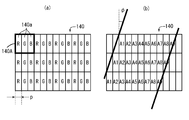
- FIG. 2A is a diagram illustrating a pixel arrangement of a display unit of a liquid crystal display
- FIG. 2B is an example of a method of arranging a plurality of viewpoint images having parallax with respect to sub-pixels. It is shown.
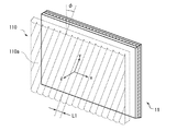
- FIG. 3 is a diagram schematically showing the relationship between a liquid crystal lens and a virtual lenticular screen formed by the liquid crystal lens.
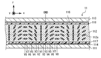
- FIG. 4 is a cross-sectional view of the liquid crystal lens perpendicular to the y direction.
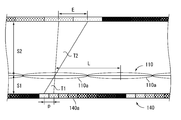
- FIG. 5 is a diagram for explaining the adjustment of the focal length and the display image in the present embodiment.
- FIG. 5 is a diagram for explaining the adjustment of the focal length and the display image in the present embodiment.
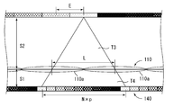
- FIG. 6 is a diagram for explaining the adjustment of the focal length and the display image in the present embodiment.
- FIG. 7 is a diagram for explaining the adjustment of the focal length and the display image in the present embodiment.
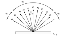
- FIG. 8 is a diagram schematically showing the relationship between the number of viewpoints, the distance between viewpoints, and a region where a stereoscopic image can be observed.
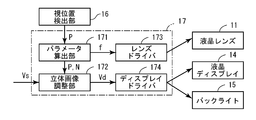
- FIG. 9 is a functional block diagram showing a procedure for adjusting the focal length and the display image in the stereoscopic display device according to the embodiment of the present invention.
- FIG. 10 is a cross-sectional view of the liquid crystal lens of the stereoscopic display device according to the first embodiment of the present invention.
- FIG. 11 is a table showing the results of adjusting the values of the potentials V1, V2,... V9 applied to the main electrodes in order to form the corresponding focal lengths when the viewing distance is 1.6 m and 3.2 m. It is.
- a stereoscopic display device includes a display panel that regularly displays images of a plurality of viewpoints having parallax with each other, and a virtual lenticular lens that is disposed in front of the display panel and is controlled by voltage control. Are arranged at regular intervals corresponding to the image of the display panel, and a control unit for controlling the display panel and the light conversion element.
- the control unit changes a focal length of the virtual lenticular lens formed by the light beam conversion element according to a distance between the display panel and an observer (first configuration).
- the parallax image displayed on the display panel is separated by the virtual lenticular lens formed by the light beam conversion element.
- the focal length of the virtual lenticular lens is changed according to the distance between the display panel and the observer, stereoscopic viewing is possible at various viewing distances.
- control unit adjusts the number of viewpoints displayed on the display panel according to a distance from an observer (second configuration).
- the number of display panel pixels per virtual lenticular lens is matched by adjusting the number of viewpoints. As a result, crosstalk associated with a change in viewing distance can be prevented.
- control unit translates the arrangement of images displayed on the display panel according to the position of the observer (third configuration).
- control unit adjusts a parallax amount of an image displayed on the display panel according to a distance from an observer (fourth configuration).
- an automatic visual position detection unit that automatically detects the position of the observer may be further provided (fifth configuration).
- the light conversion element may be a gradient index lens using a liquid crystal (sixth configuration).
- the display panel may be a liquid crystal display (seventh configuration).
- FIG. 1 is an exploded perspective view showing a schematic configuration of a stereoscopic display device 1 according to an embodiment of the present invention.
- the stereoscopic display device 1 includes a liquid crystal lens 11, a phase difference plate 12, a spacer 13, a liquid crystal display 14, and a backlight 15.
- Both the liquid crystal lens 11 and the liquid crystal display 14 have a substantially rectangular plate shape in plan view, and the sizes of the main surfaces (surfaces having the largest area) are substantially equal to each other.
- the liquid crystal lens 11 includes a pair of substrates and a liquid crystal layer sandwiched between the substrates, although a detailed configuration will be described later.
- the liquid crystal lens 11 changes the behavior of light passing through the liquid crystal layer by changing the orientation of the liquid crystal molecules in the liquid crystal layer.
- a phase difference plate 12 is disposed on the back surface of the liquid crystal lens 11.
- the phase difference plate 12 adjusts the polarization direction of the light emitted from the liquid crystal display 14 and matches the direction in which the orientation of the liquid crystal molecules of the liquid crystal lens 11 changes.
- the retardation plate 12 may not be provided depending on the polarization direction of the light emitted from the liquid crystal display 14.
- a liquid crystal display 14 is disposed on the back surface of the phase difference plate 12 via a spacer 13.
- the liquid crystal display 14 includes a display unit 140, an active matrix substrate, a color filter substrate disposed to face the active matrix substrate, and a liquid crystal layer sandwiched between the substrates.
- TFTs Thin Film Transistors
- pixel electrodes are formed in a matrix.
- the liquid crystal display 14 changes the orientation of the liquid crystal molecules in the liquid crystal layer on an arbitrary pixel electrode by controlling the TFT. Thereby, the liquid crystal display 14 can display an arbitrary image on the display unit 140.
- a backlight 15 is disposed on the back of the liquid crystal display 14.
- the backlight 15 irradiates the liquid crystal display 14 with light.
- the stereoscopic display device 1 performs stereoscopic display by controlling the liquid crystal lens 11 and the liquid crystal display 14 in conjunction with each other.
- FIG. 2A is a diagram showing a pixel arrangement of the display unit 140 of the liquid crystal display 14.
- the display unit 140 includes a large number of pixels 140A.
- Each of the pixels 140A further includes sub-pixels 140a corresponding to red (R), green (G), and blue (B).
- the sub-pixels 140a are evenly aligned at intervals p in the horizontal direction.
- the liquid crystal display 14 displays images of a plurality of viewpoints having parallax with each other (hereinafter referred to as parallax images) in a regularly arranged manner using these sub-pixels 140a as a display unit.
- FIG. 2B shows an example of a method for arranging parallax images on the sub-pixels 140a.
- images of the same viewpoint are tilted by an angle ⁇ with respect to the vertical direction.
- images of the same viewpoint are displayed while being shifted by one line in the horizontal direction every time one line is advanced in the vertical direction.
- FIG. 3 is a diagram schematically showing the relationship between the liquid crystal lens 11 and a virtual lenticular screen 110 formed by the liquid crystal lens 11.
- the virtual lenticular screen 110 is composed of a large number of virtual lenticular lenses 110a.
- the liquid crystal lens 11 forms a plurality of lenticular lenses 110a aligned at a constant interval L1 corresponding to the image displayed on the liquid crystal display 14.
- the lenticular lens 110a is arranged to be inclined by an angle ⁇ corresponding to the image on the liquid crystal display 14.
- the alignment direction of the lenticular lens 110a is referred to as the x direction
- the extending direction of the lenticular lens 110a is referred to as the y direction
- the thickness direction of the liquid crystal lens 11 is referred to as the z direction.
- FIG. 4 is a cross-sectional view of the liquid crystal lens 11 perpendicular to the y direction.
- the liquid crystal lens 11 includes a control substrate 111, a counter substrate 113, and a liquid crystal layer 112 sandwiched between both substrates.
- the liquid crystal molecules 112a constituting the liquid crystal layer 112 have positive dielectric anisotropy.
- the liquid crystal molecules 112a have birefringence. That is, the refractive index n e for the light vibrating in parallel with the optical axis, the refractive index n o for light oscillating perpendicularly to the optical axis are different.
- a plurality of main electrodes 114 are formed on the control substrate 111.
- Each of the main electrodes 114 is formed in an elongated shape along the y direction, and is arranged at an interval L1 along the x direction so that they are substantially parallel to each other.
- An alignment film 117 is formed so as to cover the main electrode 114.
- a common electrode 116 is formed on the entire surface of the counter substrate 113.
- An alignment film 118 is formed so as to cover the common electrode 116.
- the alignment films 117 and 118 a plurality of grooves are formed in parallel to the x direction by an alignment process. With the alignment films 117 and 118, the liquid crystal molecules 112 a are aligned so that the molecular major axis is parallel to the x direction when no voltage is applied to the liquid crystal layer 112 (no voltage applied state).
- the liquid crystal molecules 112a are aligned so that the electric field and the molecular long axis are parallel. As shown in FIG. 4, the molecular long axes of the liquid crystal molecules 112a in the vicinity of the main electrode 114 are aligned parallel to the z direction. As the distance from the main electrode 114 increases, the major axis of the liquid crystal molecules 112a is inclined from the z direction to the x direction.
- the refractive index of the liquid crystal layer 112 changes according to the change in the alignment direction of the liquid crystal molecules 112a. Therefore, the liquid crystal layer 112 has a refractive index distribution in the x direction.
- the liquid crystal layer 112 can collect the light incident on the liquid crystal layer 112 by this refractive index distribution, as indicated by the dashed arrows in FIG. That is, the liquid crystal lens 11 functions as a gradient index lens (Gradient Index Lens, GRIN lens).
- the liquid crystal lens 11 can control the lens shape and change the focal length by controlling the potential difference between the main electrode 114 and the common electrode 116.
- the liquid crystal lens 11 does not function as a GRIN lens.
- the stereoscopic display device 1 can switch between two-dimensional image display and three-dimensional image display by controlling the liquid crystal lens 11 and the liquid crystal display 14 in conjunction with each other.
- liquid crystal lens 11 in the present embodiment has been described above.
- the case where the liquid crystal molecules 112a constituting the liquid crystal layer 112 have positive dielectric anisotropy has been described.
- liquid crystal molecules 112a having negative dielectric anisotropy may be used.
- a GRIN lens is configured by applying a voltage of one level.
- the sub-pixels 140a are arranged at intervals p.
- a lenticular screen 110 is arranged at a distance S1 from the display surface.
- the lenticular screen 110 is composed of a plurality of lenticular lenses 110a, and the lenticular lenses 110a are aligned at intervals (pitch) L. Note that L and L1 satisfy the following relationship.
- the focal length f of the lenticular lens 110a needs to satisfy the following equation.
- N ′ satisfies the following relationship derived in the same manner as Equation (3).
- N ' 8.95.
- the number of sub-pixels 140a corresponding to one line of lenticular lens 110a is 8.95 points
- the number of sub-pixels 140a corresponding to 100 lines of lenticular lens 110a is 895 points.
- the number of sub-pixels 140a corresponding to the 100-line lenticular lens 110a is 900 points, so that 5 points can be evenly thinned out. That is, display of one viewpoint may be skipped for each 20-line lenticular lens 110a.
- a change in the viewing distance S2 is detected to obtain the optimum number of viewpoints N and focal length f. Then, the number of viewpoints N is adjusted by the liquid crystal display 14, and the focal length f is adjusted by the liquid crystal lens 11.
- FIG. 8 is a diagram schematically showing the relationship between the number of viewpoints N, the distance between viewpoints E, and a region (hereinafter referred to as a viewing zone) VR in which a stereoscopic image can be observed.
- Arrows A1, A2,... A9 represent positions where images of the respective viewpoints are observed.
- the viewing zone VR is also finite.
- reverse viewing occurs in which the image to be projected on the right eye and the image to be projected on the left eye are interchanged.
- the stereoscopic display device 1 detects a change in the position of the observer as will be described later. Then, according to the position of the observer, the arrangement of the parallax images is translated to prevent the occurrence of reverse viewing.
- FIG. 9 is a functional block diagram showing the adjustment procedure of the focal length f and the display image in the stereoscopic display device 1.
- the stereoscopic display device 1 further includes a visual position detection unit 16 and a control unit 17 in addition to the configuration described above.
- the visual position detection unit 16 outputs the observer's position P to the control unit 17.
- the visual position detection unit 16 is preferably one that automatically detects the position P of the observer by combining a camera and an image processing circuit, but is like a controller in which the observer manually inputs the position P. It may be.
- the control unit 17 receives the observer's position P from the visual position detection unit 16, and receives an image signal Vs from the outside. And based on these information, the liquid crystal lens 11, the liquid crystal display 14, and the backlight 15 are controlled.
- the control unit 17 may be mounted as a module on the substrate constituting the liquid crystal lens 11 or the liquid crystal display 14, or may be a separate component. Further, all of the control unit 17 may not be implemented as hardware. That is, a part of the control unit 17 may be a virtual functional block realized by a processor executing a computer program.
- the control unit 17 includes a parameter calculation unit 171, a stereoscopic image adjustment unit 172, a lens driver 173, and a display driver 174.
- the parameter calculation unit 171 receives the observer position P output from the visual position detection unit 16. Then, the focal length f and the number N of viewpoints are calculated based on the viewing distance S2 included in the position P of the observer. Thereafter, the focal length f is output to the lens driver 173. Further, the observer's position P and the number of viewpoints N are output to the stereoscopic image adjustment unit 172.
- the stereoscopic image adjustment unit 172 receives the observer's position P and the number of viewpoints N output from the parameter calculation unit 171. In addition, the stereoscopic image adjustment unit 172 receives the image signal Vs from the outside.
- the image signal Vs is multi-channel data including images taken from two or more directions, for example.
- the stereoscopic image adjustment unit 172 generates N viewpoint image data from the M channel image data, where M is the number of channels of the received image.
- the generation of image data by the stereoscopic image adjustment unit 172 can be performed by regularly skipping display of a specific viewpoint as described above. Further, N viewpoint image data may be reconstructed by interpolating M channel image data or the like. At this time, it is desirable to adjust the amount of parallax between the images of the respective viewpoints according to the viewing distance S2. By adjusting the amount of parallax, a more natural stereoscopic effect can be given to the observer. The smaller the viewing distance S2, the larger the parallax amount, and the larger the viewing distance S2, the smaller the parallax amount.
- the arrangement of the parallax images may be translated so that reverse viewing does not occur.
- the image signal Vs may include a two-dimensional image and depth information of each pixel.
- the stereoscopic image adjustment unit 172 may be configured to estimate a stereoscopic image from a single-channel two-dimensional image and generate N viewpoint image data.
- the stereoscopic image adjustment unit 172 outputs the generated N viewpoint image data to the display driver 174 as an image signal Vd.
- the lens driver 173 receives the focal length f output from the parameter calculation unit 171 and drives the liquid crystal lens 11 based on this value.
- the display driver 174 receives the image signal Vd output from the stereoscopic image adjustment unit 172, and drives the liquid crystal display 14 and the backlight 15 based on this signal.
- the configuration of the stereoscopic display device 1 and the adjustment procedure of the focal length f and the display image by the stereoscopic display device 1 have been described in the present embodiment.
- stereoscopic vision is possible in a wide viewing position by controlling the focal length f.
- the focal length f can be controlled by controlling the voltage applied to the liquid crystal lens 11.
- the number of electrodes may be small.
- the lens pitch even if the amount of change is small, a large number of cylindrical lenses 110a are aligned, so the orientation direction of the liquid crystal molecules 112a must be changed greatly.
- the focal length f is changed as in the present embodiment, if the amount of change is small, the amount of change in the alignment direction of the liquid crystal molecules 112a is also small. Therefore, the response speed can be increased.
- the pixel arrangement of the display unit 140 a configuration in which red, green, and blue sub-pixels 140a are aligned in the horizontal direction in the pixel 140A is illustrated.
- the pixel 140A may include more subpixels, or may include subpixels that display other colors.
- the arrangement method of the sub-pixels 140a in the pixel 140A is arbitrary, and the sub-pixels 140a may be arranged in the vertical direction or divided into a plurality of columns.
- parallax images are arranged in a stripe pattern on the display unit 140.
- the arrangement method of the images of a plurality of viewpoints is arbitrary as long as they are regularly arranged and displayed, and the liquid crystal lens 11 may be adjusted according to this.
- the optimum distance for viewing the display is generally said to be three times the vertical length of the display. From this, the optimum viewing distance S2 is set to 1.6 m, and each element is designed.
- the liquid crystal lens 11 was designed as follows. As shown in FIG. 10, 15 main electrodes 114 are arranged at equal intervals with respect to one lenticular lens 110a, and eight-level potentials (V1, V2,... V8) are symmetrical with respect to the center line of the lenticular lens 110a. In addition to the above, an electric field can be formed.
- the common electrode 116 was set to the ground potential.
- the width of each main electrode 114 was about 20 ⁇ m, and the interval between the main electrodes 114 was 97.5 ⁇ .
- FIG. 11 shows the result of adjusting the values of the potentials V1, V2,... V8 applied to the main electrode 114 in order to form the corresponding focal length f when the viewing distance S2 is 1.6 m and 3.2 m. It is a table
- the stereoscopic display device 1 is designed so that this value has a margin and the distance E between viewpoints when observed at the shortest viewing distance S2 is 16.25 mm.
- the present invention can be industrially used as a stereoscopic display device capable of autostereoscopic viewing.
Landscapes
- Physics & Mathematics (AREA)
- Engineering & Computer Science (AREA)
- General Physics & Mathematics (AREA)
- Multimedia (AREA)
- Signal Processing (AREA)
- Nonlinear Science (AREA)
- Chemical & Material Sciences (AREA)
- Crystallography & Structural Chemistry (AREA)
- Optics & Photonics (AREA)
- Mathematical Physics (AREA)
- Computer Hardware Design (AREA)
- Theoretical Computer Science (AREA)
- Geometry (AREA)
- Testing, Inspecting, Measuring Of Stereoscopic Televisions And Televisions (AREA)
- Stereoscopic And Panoramic Photography (AREA)
- Liquid Crystal (AREA)
Abstract
広い視位置において立体視が可能な、立体表示装置の構成を得る。立体表示装置(1)は、互いに視差を有する複数の視点の画像を規則的に並べて表示する表示パネル(14)と、前記表示パネル(14)の前面に配置され、電圧制御により仮想的なレンチキュラレンズを前記表示パネル(14)の画像に対応して一定の間隔で整列して形成する光線変換素子(11)と、前記表示パネル(14)および前記光線変換素子(11)を制御する制御部とを備える。前記制御部は、前記表示パネル(14)と観察者との距離に応じて、前記光線変換素子(11)が形成する前記仮想的なレンチキュラレンズの焦点距離を変更する。
Description
本発明は、立体表示装置に関し、より詳しくは、裸眼立体視が可能な立体表示装置に関する。
従来、特殊な眼鏡等を装着する必要がない、いわゆる裸眼立体視が可能な立体表示装置が知られている。特開2007-336002号公報には、いわゆる多眼方式による立体表示装置が開示されている。
特開2007-336002号公報に記載の立体表示装置の原理は、概ね次の通りである。立体表示装置は、表示面に多方向から撮影した画像を規則的に並べて表示する。表示面の前面には、複数のレンチキュラレンズが、一定の間隔で配置されている。レンチキュラレンズによって、多方向から撮影された画像の各々が分離される。ユーザは、この表示装置を最適な位置で観察することで、分離された画像を左右の眼で観察し、視差による立体感を感じることができる。
特開2010-282090号公報には、表示パネルと可変レンズアレイ素子を備えた立体表示装置が開示されている。可変レンズアレイ素子は、水平方向には少なくとも表示パネルのサブピクセルの水平方向の配列位置ごとに電極が設けられており、シリンドリカルレンズの形状をサブピクセル単位で変化させる。
特開2010-282090号公報には、シリンドリカルレンズのレンズピッチを変更することで、1つのシリンドリカルレンズに対応させる表示パネルの水平方向の画素数を変化させ、視点数を変化させることができると記載されている。
多眼方式による立体表示装置では、あらかじめ観察者が視聴する位置を仮定して、その位置を最適視位置として各要素の設計が行われる。そのため、最適視位置から外れると、正常な立体画像を得られない。例えば、右目に映るべき画像と左目に映るべき画像とが入れ替わったり(逆視)、複数の視点の画像が混ざる(クロストーク)といった現象が起こる。これらは、観察者に違和感や疲労感を与える原因となる。
特開2010-282090号公報に記載の立体表示装置は、可変レンズアレイ素子によって、シリンドリカルレンズの形状をサブピクセル単位で変化させる。この文献には、観察者の視聴位置の水平方向の移動に応じてシリンドリカルレンズの位置を変化させることで、逆視やクロストークを防止することができると記載されている。
しかしながら、特開2010-282090号公報に記載の立体表示装置では、シリンドリカルレンズの位置を細かく調整するために、多数の電極を細かく配置する必要がある。
また、特開2010-282090号公報には、表示パネルに対して垂直な方向への視位置の移動(視距離の変化)に関しては触れられていない。
仮に、レンズピッチの変更によって視距離の変化に対応しようとした場合、視距離の変化に伴って変更すべきレンズピッチの量はごく僅かである。そのため、それに対応したレンズピッチを形成するための多数の電極を形成する必要がある。
また、可変レンズアレイを液晶レンズで構成した場合、レンズピッチを変更させる電位変化に対して、液晶の応答速度が遅くなるという問題がある。
本発明の目的は、広い視位置において立体視が可能な、立体表示装置の構成を得ることである。
ここに開示する立体表示装置は、互いに視差を有する複数の視点の画像を規則的に並べて表示する表示パネルと、前記表示パネルの前面に配置され、電圧制御により仮想的なレンチキュラレンズを前記表示パネルの画像に対応して一定の間隔で整列して形成する光線変換素子と、前記表示パネルおよび前記光線変換素子を制御する制御部とを備える。前記制御部は、前記表示パネルと観察者との距離に応じて、前記光線変換素子が形成する前記仮想的なレンチキュラレンズの焦点距離を変更する。
本発明によれば、広い視位置において立体視が可能な、立体表示装置の構成が得られる。
本発明の一実施形態にかかる立体表示装置は、互いに視差を有する複数の視点の画像を規則的に並べて表示する表示パネルと、前記表示パネルの前面に配置され、電圧制御により仮想的なレンチキュラレンズを前記表示パネルの画像に対応して一定の間隔で整列して形成する光線変換素子と、前記表示パネルおよび前記光線変換素子を制御する制御部とを備える。前記制御部は、前記表示パネルと観察者との距離に応じて、前記光線変換素子が形成する前記仮想的なレンチキュラレンズの焦点距離を変更する(第1の構成)。
上記の構成によれば、光線変換素子によって形成される仮想的なレンチキュラレンズによって、表示パネルに表示された視差画像が分離される。表示パネルと観察者との距離に応じて、仮想的なレンチキュラレンズの焦点距離を変更することによって、様々な視距離において立体視が可能になる。
上記第1の構成において、前記制御部は、観察者との距離に応じて、前記表示パネルが表示する前記視点の数を調整することが好ましい(第2の構成)。
上記の構成によれば、視点数を調整することによって、仮想的なレンチキュラレンズの1つあたりの表示パネルの画素数を整合させる。これにより、視距離の変化に伴う、クロストークを防止することができる。
上記第1または第2の構成において、前記制御部は、観察者の位置に応じて、前記表示パネルが表示する画像の配置を平行移動させることが好ましい(第3の構成)。
上記の構成によれば、逆視を防止して、立体視ができる視位置を広げることができる。
上記第1~第3のいずれかの構成において、前記制御部は、観察者との距離に応じて、前記表示パネルが表示する画像の視差量を調整することが好ましい(第4の構成)。
上記の構成によれば、観察者により自然な立体感を与えることができる。
上記第1~第4のいずれかの構成において、観察者の位置を自動的に検出する自動視位置検出部をさらに備えていても良い(第5の構成)。
上記第1~第5のいずれかの構成において、前記光線変換素子は、液晶を使用した屈折率分布型レンズとすることができる(第6の構成)。
上記第1~第6のいずれかの構成において、前記表示パネルは、液晶ディスプレイとすることができる(第7の構成)。
[実施の形態]
以下、図面を参照し、本発明の実施の形態を詳しく説明する。図中同一または相当部分には同一符号を付してその説明は繰り返さない。なお、説明を分かりやすくするために、以下で参照する図面においては、構成が簡略化または模式化して示されたり、一部の構成部材が省略されたりしている。また、各図に示された構成部材間の寸法比は、必ずしも実際の寸法比を示すものではない。
以下、図面を参照し、本発明の実施の形態を詳しく説明する。図中同一または相当部分には同一符号を付してその説明は繰り返さない。なお、説明を分かりやすくするために、以下で参照する図面においては、構成が簡略化または模式化して示されたり、一部の構成部材が省略されたりしている。また、各図に示された構成部材間の寸法比は、必ずしも実際の寸法比を示すものではない。
図1は、本発明の一実施形態にかかる立体表示装置1の概略構成を示す分解斜視図である。立体表示装置1は、液晶レンズ11、位相差板12、スペーサ13、液晶ディスプレイ14、およびバックライト15を備えている。
液晶レンズ11および液晶ディスプレイ14は、ともに平面視で概略矩形の板状形状で、主面(最も面積の大きい面)の大きさが、互いに略等しく形成されている。
液晶レンズ11は、詳しい構成は後述するが、一対の基板と、これに挟持された液晶層とを備える。液晶レンズ11は、液晶層内の液晶分子の配向を変化させることで、液晶層を通る光の挙動を変化させる。
液晶レンズ11の背面には、位相差板12が配置されている。位相差板12は、液晶ディスプレイ14から出射される光の偏光方向を調整し、液晶レンズ11の液晶分子の配向が変化する方向と一致させる。なお、本実施形態では位相差板12を使用するが、液晶ディスプレイ14から出射される光の偏光方向によっては、位相差板12はなくても良い。
位相差板12の背面には、スペーサ13を介して、液晶ディスプレイ14が配置されている。液晶ディスプレイ14は、表示部140と、アクティブマトリクス基板と、これに対向して配置されたカラーフィルタ基板と、両基板に挟持された液晶層とを備えている。アクティブマトリクス基板には、TFT(Thin Film Transistor)と画素電極とがマトリクス状に形成されている。液晶ディスプレイ14は、TFTを制御することによって、任意の画素電極上の液晶層内の液晶分子の配向を変化させる。これにより、液晶ディスプレイ14は、任意の画像を表示部140に表示することができる。
液晶ディスプレイ14の背面には、バックライト15が配置されている。バックライト15は、液晶ディスプレイ14に光を照射する。
立体表示装置1は、液晶レンズ11と、液晶ディスプレイ14とを連動して制御することによって、立体表示を行う。
図2(a)は、液晶ディスプレイ14の表示部140の画素配置を示した図である。表示部140は、多数の画素140Aから構成されている。画素140Aのそれぞれはさらに、赤(R)、緑(G)、青(B)に対応するサブ画素140aから構成されている。サブ画素140aは水平方向に間隔pで均等に整列している。液晶ディスプレイ14は、これらのサブ画素140aを表示単位として、互いに視差を有する複数の視点の画像(以下、視差画像と言う)を規則的に並べて表示する。
図2(b)は、視差画像の、サブ画素140aへの配置の仕方の一例を示したものである。図2(b)に示すように、同一視点の画像(図2(b)中にA1,A2,・・・A9の番号を付して示す)を、鉛直方向に対し角度φだけ傾けて配置する。図2(b)の例では、同一視点の画像を、鉛直方向に1ライン進む毎に水平方向に1ラインずらして表示している。このような表示をするのは、同一視点の画像の整列方向とサブ画素の整列方向とを一致させた場合(φ=0の場合)、特定の視点で発色が偏ったり、モアレが目立ったりする場合があるためである。
図3は、液晶レンズ11と、液晶レンズ11によって形成される仮想的なレンチキュラスクリーン110との関係を模式的に示した図である。仮想的なレンチキュラスクリーン110は、多数の仮想的なレンチキュラレンズ110aから構成される。液晶レンズ11は、液晶ディスプレイ14に表示される画像に対応して、一定の間隔L1で整列した複数のレンチキュラレンズ110aを形成する。レンチキュラレンズ110aは、液晶ディスプレイ14の画像に対応して、角度φだけ傾けて配置される。
以下では、このレンチキュラレンズ110aの整列方向をx方向、レンチキュラレンズ110aの延在方向をy方向、液晶レンズ11の厚さ方向をz方向と呼んで参照する。
図4は、液晶レンズ11の、y方向に垂直な断面図である。液晶レンズ11は、制御基板111と、対向基板113と、両基板に挟持された液晶層112とを備える。
本実施形態では、液晶層112を構成する液晶分子112aとして、誘電率異方性が正のものを用いる。液晶分子112aは、複屈折性を有している。すなわち、光学軸に平行に振動する光に対する屈折率neと、光学軸に垂直に振動する光に対する屈折率noとが異なっている。液晶分子112aは、Δn=ne-noの値の大きいものが好ましい。
制御基板111には、複数の主電極114が形成されている。主電極114のそれぞれはy方向に沿って細長に形成され、それらが互いに略平行になるようにx方向に沿って間隔L1で配置されている。
主電極114を覆って、配向膜117が形成されている。
対向基板113には、全面に共通電極116が形成されている。共通電極116を覆って、配向膜118が形成されている。
配向膜117および118には、配向処理によって、x方向と平行に複数の溝が形成されている。配向膜117および118によって、液晶層112に電圧が印加されていない状態(電圧無印加状態)では、液晶分子112aは、分子長軸がx方向と平行になるように配向する。
主電極114と共通電極116との間に電圧が印加されると、この電圧によって電界が生じる。液晶分子112aは、電界と分子長軸とが平行になるように配向する。図4に示すように、主電極114近傍の液晶分子112aの分子長軸は、z方向と平行に配向する。主電極114から離れるにつれて、液晶分子112aの長軸は、z方向からx方向に傾いていく。
液晶分子112aの配向方向の変化にしたがって、液晶層112の屈折率が変化する。そのため、液晶層112は、x方向に屈折率分布を有する。液晶層112は、この屈折率分布によって、図4に破線の矢印で示したように、液晶層112に入射した光を集光することができる。すなわち、液晶レンズ11は屈折率分布型レンズ(Gradient Index Lens、GRINレンズ)として機能する。
液晶レンズ11は、主電極114と共通電極116との間の電位差を制御することによって、レンズ形状を制御し、焦点距離を変化させることができる。
また、電圧無印加状態では、液晶分子112aは配向膜117および118により一様に配向しているため、液晶レンズ11はGRINレンズとして機能しない。立体表示装置1は、液晶レンズ11と液晶ディスプレイ14とを連動して制御して、2次元画像表示と3次元画像表示とを切り替えることができる。
以上、本実施形態における液晶レンズ11の構成を説明した。本実施形態では、液晶層112を構成する液晶分子112aとして、誘電率異方性が正のものを用いる場合を説明した。しかし、液晶分子112aとして、誘電率異方性が負のものを用いても良い。
また、本実施形態では、簡単のため1水準の電圧を印加してGRINレンズを構成する例を示した。しかし、GRINレンズ1ピッチあたりに、複数の電極を配置して、多水準の電圧を印加することが好ましい。レンズ形状をより緻密に形成できるためである。
[焦点距離fおよび表示画像の調整]
次に、図5~図7を用いて、本実施形態による焦点距離fおよび表示画像の調整について説明する。
次に、図5~図7を用いて、本実施形態による焦点距離fおよび表示画像の調整について説明する。
図5に示すように、表示部140には、サブ画素140aが間隔pで整列している。サブ画素140aを表示単位として、互いに視差を有するN個(図5~図7ではN=9の場合を例示している)の視点の画像が並べて表示されている。
表示面から距離S1だけ隔てて、レンチキュラスクリーン110が配置されている。レンチキュラスクリーン110は、複数のレンチキュラレンズ110aから構成されており、レンチキュラレンズ110aは、間隔(ピッチ)Lで整列している。なお、LとL1とは下記の関係を満たす。
L1=Lcosφ (1)
表示部140を、レンチキュラスクリーン110から視距離S2だけ離れた位置で観察する場合を考える。隣接したサブ画素140aに表示された画像が、この観察位置で視点間距離Eだけ離れるように分離されるためには、図5に示した2つの三角形T1とT2の相似関係から、次の式を満たす必要がある。
S1:p=S2:E (2)
さらに、視点数Nと、レンチキュラレンズ110aのピッチLとの間には、図6に示した三角形T3とT4の相似関係から、次の関係が成り立つ。
S2:L=S1+S2:N×p (3)
式(2)(3)に加えて、レンチキュラレンズ110aの焦点距離fが、下記の式を満たす必要がある。
1/S1+1/S2=1/f (4)
次に、ピッチLおよび距離S1を変化させずに、表示部140を、レンチキュラスクリーン110から視距離S2’(S2’>S2)だけ離れた位置で観察する場合を考える。このときの視点間距離E’は、式(2)よりE’=S2’/S2×Eとなる。図7に示すように、この状態では、レンチキュラレンズ110aのピッチLと、表示部140上に同一視点が表示されるまでの間隔とが対応しておらず、異なる視点の画像が混ざって観察されるクロストークが発生する。
ピッチLおよび距離S1を変化させずに、クロストークを防止するためには、表示部140側で、同一視点が表示されるまでの間隔を変化させる必要がある。ここで、サブ画素140aのピッチpを変化させることは現実的ではないため、視点数をNからN’に変化させることを考える。N’は、式(3)と同様にして導かれる次の関係を満たす。
S2’:L=S1+S2’:N’×p (5)
ここで、N’が非整数の場合の取り扱いについて述べる。例えば、N’=8.95の場合を考える。1ラインのレンチキュラレンズ110aに対応するサブ画素140aの数が8.95点ということは、100ラインのレンチキュラレンズ110aに対応するサブ画素140aの数は895点ということになる。N=9の場合は、100ラインのレンチキュラレンズ110aに対応するサブ画素140aの数は900点であるから、そこから5点を均等に間引けば良い。すなわち、20ラインのレンチキュラレンズ110a毎に、1つの視点の表示をスキップすれば良い。
上記に加え、レンチキュラレンズ110aの焦点距離を下記の焦点距離f’に変化させる必要がある。
1/S1+1/S2’=1/f’ (6)
本実施形態にかかる立体表示装置1では、後述するように、視距離S2の変化を検出して、最適な視点数Nおよび焦点距離fを求める。そして、視点数Nの調整を液晶ディスプレイ14により行い、焦点距離fの調整を液晶レンズ11により行う。
以上は、観察者が立体表示装置1の表示部140と垂直な方向に移動した場合(視距離S2が変化した場合)における焦点距離fおよび表示画像の調整手順である。次に、観察者が立体表示装置1の表示部140と平行に移動した場合について説明する。
図8は、視点数N、視点間距離E、および立体画像を観察可能な領域(以下、視域という)VRとの関係を模式的に示した図である。矢印A1,A2・・・A9は、各視点の画像が観察される位置を表している。図8に示すように、多眼方式では視点数Nが有限であるため(図8ではN=9)、視域VRも有限である。視域VRから外れた領域VRIでは、右目に映るべき画像と左目に映るべき画像とが入れ替わる逆視が発生する。
本実施形態にかかる立体表示装置1は、後述するように、観察者の位置の変化を検出する。そして、観察者の位置に応じて、視差画像の配置を平行移動させて、逆視の発生を防止する。
図9は、立体表示装置1における、焦点距離fおよび表示画像の調整手順を示す機能ブロック図である。立体表示装置1は、既述の構成に加えてさらに、視位置検出部16と、制御部17とを備えている。
視位置検出部16は、観察者の位置Pを制御部17へ出力する。視位置検出部16は、カメラと画像処理回路とを組み合わせる等して、観察者の位置Pを自動的に検出するものが好ましいが、観察者がマニュアルで位置Pを入力するコントローラのようなものであっても良い。
制御部17は、視位置検出部16から観察者の位置Pを受け取り、外部から画像信号Vsを受け取る。そして、これらの情報をもとに、液晶レンズ11、液晶ディスプレイ14、およびバックライト15を制御する。制御部17は、液晶レンズ11または液晶ディスプレイ14を構成する基板等にモジュールとして実装されていても良いし、これらとは別の部品であっても良い。また、制御部17の全てがハードウェアとして実装されていなくても良い。すなわち、制御部17の一部は、コンピュータプログラムをプロセッサが実行することによって実現される仮想的な機能ブロックであっても良い。
制御部17は、パラメータ算出部171と、立体画像調整部172と、レンズドライバ173と、ディスプレイドライバ174とを備える。
パラメータ算出部171は、視位置検出部16から出力された観察者の位置Pを受け取る。そして、観察者の位置Pに含まれる視距離S2に基づいて焦点距離fおよび視点数Nを算出する。その後、焦点距離fをレンズドライバ173に出力する。また、観察者の位置Pおよび視点数Nを立体画像調整部172に出力する。
立体画像調整部172は、パラメータ算出部171から出力された、観察者の位置Pおよび視点数Nを受け取る。また、立体画像調整部172は、外部から画像信号Vsを受け取る。
画像信号Vsは、例えば、2つ以上の方向から撮影された画像を含む多チャンネルデータである。受け取った画像のチャンネル数をMとして、立体画像調整部172は、Mチャンネルの画像データからN視点の画像データを生成する。
立体画像調整部172による画像データの生成は、既述のように規則的に特定の視点の表示をスキップすることにより行うことができる。また、Mチャンネルの画像データの補間等を行って、N視点の画像データを再構築しても良い。このとき、視距離S2に応じて、各視点の画像間の視差量を調整することが望ましい。視差量を調整することによって、観察者に、より自然な立体感を与えることができる。視距離S2が小さいほど視差量は大きくなり、視距離S2が大きくなるほど視差量は小さくなる。
さらに、観察者の位置Pに応じて、逆視が発生しないように、視差画像の配置を平行移動させても良い。
画像信号Vsは、上記の他、2次元画像とその各画素の深度情報とを含むようなものであっても良い。あるいは、立体画像調整部172が、シングルチャンネルの2次元画像から立体画像を推定し、N視点の画像データを生成する構成としても良い。
立体画像調整部172は、生成したN視点の画像データを、画像信号Vdとしてディスプレイドライバ174に出力する。
レンズドライバ173は、パラメータ算出部171から出力される焦点距離fを受け取り、この値に基づいて液晶レンズ11を駆動する。
ディスプレイドライバ174は、立体画像調整部172から出力される画像信号Vdを受け取り、この信号に基づいて液晶ディスプレイ14およびバックライト15を駆動する。
以上、本実施形態に立体表示装置1の構成および、立体表示装置1による焦点距離fおよび表示画像の調整手順について説明した。
立体表示装置1によれば、焦点距離fを制御することにより、広い視位置において立体視が可能になる。焦点距離fの制御は、液晶レンズ11に印加する電圧の制御によって行うことができる。
レンズピッチの調整によって視位置の調整を行う場合、レンズピッチの調整に必要な分解能を得るために多数の電極が必要である。本実施形態の場合は、電極の数は少なくても良い。
また、レンズピッチを変更する場合、変更量が僅かであっても、多数のシリンドリカルレンズ110aが整列しているため、液晶分子112aの配向方向を大きく変えなければならない。一方、本実施形態の様に焦点距離fを変更する場合、変更量が僅かであれば、液晶分子112aの配向方向の変化量も僅かである。そのため、応答速度を速くできる。
本実施形態では、表示部140の画素配置として、画素140A内に、赤、緑、青のサブ画素140aが、水平方向に整列した構成を例示した。しかし、画素140Aは、さらに多くのサブ画素を備えても良く、他の色を表示するサブ画素を備えていても良い。また、画素140A内でのサブ画素140aの配置の方法も任意であり、鉛直方向に整列させたり、複数の列に分割して配置しても良い。
本実施形態では、表示部140に視差画像を、ストライプ状に並べて配置した。しかし、複数の視点の画像の配置方法は、規則的に並べて表示する限り任意であり、これに合わせて液晶レンズ11を調整すれば良い。
以下では、数値を含んだより具体的な構成例を説明する。この構成例は、本実施形態を限定するものではない。
[第1の実施形態]
視点間距離E=16.25mm、視点数N=9、液晶ディスプレイ14を対角42インチ(1066.8mm)のフルハイビジョン(解像度:1920×1080画素)ディスプレイとして、立体表示装置1を設計する。液晶ディスプレイ14の画素140Aは正方形とし、水平方向に、赤、緑、青のサブ画素140aで3等分されているものとする。そうすると、画素140Aの一辺の大きさは約484.5μmであり、サブ画素140aの水平方向の間隔pは約161.5μmとなる。また、角度φは18.4°である。
視点間距離E=16.25mm、視点数N=9、液晶ディスプレイ14を対角42インチ(1066.8mm)のフルハイビジョン(解像度:1920×1080画素)ディスプレイとして、立体表示装置1を設計する。液晶ディスプレイ14の画素140Aは正方形とし、水平方向に、赤、緑、青のサブ画素140aで3等分されているものとする。そうすると、画素140Aの一辺の大きさは約484.5μmであり、サブ画素140aの水平方向の間隔pは約161.5μmとなる。また、角度φは18.4°である。
ディスプレイを視聴するのに最適な距離は、一般的に、ディスプレイの縦方向の長さの3倍と言われている。これから、最適視距離S2を1.6mに設定し、各要素の設計を行う。
式(2)より、S1=14.902mmとなる。式(3)より、L=1439.199μm、式(1)よりL1=1365.342μmとなる。さらに、式(4)によりf=14.745mmとなる。
以上のように、最適視距離S2=1.6mで設計した立体表示装置1を、視距離S2’=3.2mの位置で観察する場合を考える。式(5)よりN’=8.96、式(6)よりf’=15.823となる。
このような焦点距離f,f’を持つレンチキュラレンズ110aを実現するため、液晶レンズ11を次のように設計した。図10に示すように、1つのレンチキュラレンズ110aに対し15本の主電極114を等間隔に配置し、8水準の電位(V1,V2,・・・V8)をレンチキュラレンズ110aの中心線に対称に加えて電界を形成できるようにした。なお、共通電極116は接地電位とした。各主電極114の幅は約20μm、各主電極114間の間隔は97.5μとした。液晶層112を構成する液晶分子112aとして、Δn=0.17のものを使用した。
図11は、視距離S2が1.6mおよび3.2mの場合において、対応する焦点距離fを形成するために主電極114に印加する電位V1,V2,・・・V8の値を調整した結果を示す表である。
[第2の実施形態]
第1の実施形態では、通常よりも視距離S2を長くする場合を考えた。次に、通常よりも視距離S2を短くする場合を考える。
第1の実施形態では、通常よりも視距離S2を長くする場合を考えた。次に、通常よりも視距離S2を短くする場合を考える。
視距離S2を短くする場合には、視点間距離Eが短くなることを考慮する必要がある。視点間距離Eが短くなると、視域VRも狭くなる(図8参照)。視域VRが、両目の間隔(一般的には65mmと言われている)よりも狭くなると、立体像を観察することができなくなる。したがって、例えば9視点の場合、視点間距離Eは、少なくとも65mm/8=8.125mm以上である必要がある。この値に余裕を持たせて、最も短い視距離S2で観察した場合の視点間距離Eが16.25mmとなるように、立体表示装置1を設計する。
例えば、視距離S2=1.2mと、視距離S2=1.6mとの両方で観察できる立体表示装置1を設計する場合、視距離S2=1.2mにおいて、視点間距離Eが16.25mmとなるように設計を行う。
視点間距離E=16.25mm、視点数N=9、液晶ディスプレイ14を対角42インチのフルハイビジョンディスプレイとし、視距離S2=1.2mとすると、式(2)より、S1=11.926mm、式(1)および(3)よりL1=1365.342μm、式(4)よりf=11.809mmとなる。
以上のように、最適視距離S2=1.2mで設計した立体表示装置1を、視距離S2’=1.6mの位置で観察する場合、式(5)よりN’=8.98、式(6)よりf’=11.838となる。
[その他の実施形態]
以上、本発明についての実施形態を説明したが、本発明は上述の各実施形態のみに限定されず、発明の範囲内で種々の変更や組み合わせが可能である。
以上、本発明についての実施形態を説明したが、本発明は上述の各実施形態のみに限定されず、発明の範囲内で種々の変更や組み合わせが可能である。
本発明は、裸眼立体視が可能な立体表示装置として産業上の利用が可能である。
Claims (7)
- 互いに視差を有する複数の視点の画像を規則的に並べて表示する表示パネルと、
前記表示パネルの前面に配置され、電圧制御により仮想的なレンチキュラレンズを前記表示パネルの画像に対応して一定の間隔で整列して形成する光線変換素子と、
前記表示パネルおよび前記光線変換素子を制御する制御部とを備え、
前記制御部は、前記表示パネルと観察者との距離に応じて、前記光線変換素子が形成する前記仮想的なレンチキュラレンズの焦点距離を変更する、立体表示装置。 - 前記制御部は、観察者との距離に応じて、前記表示パネルが表示する前記視点の数を調整する、請求項1に記載の立体表示装置。
- 前記制御部は、観察者の位置に応じて、前記表示パネルが表示する画像の配置を平行移動させる、請求項1または2に記載の立体表示装置。
- 前記制御部は、観察者との距離に応じて、前記表示パネルが表示する画像の視差量を調整する、請求項1~3のいずれか一項に記載の立体表示装置。
- 観察者の位置を自動的に検出する自動視位置検出部をさらに備える、請求項1~4のいずれか一項に記載の立体表示装置。
- 前記光線変換素子は、液晶を使用した屈折率分布型レンズである、請求項1~5のいずれか一項に記載の立体表示装置。
- 前記表示パネルは、液晶ディスプレイである、請求項1~6のいずれか一項に記載の立体表示装置。
Priority Applications (1)
| Application Number | Priority Date | Filing Date | Title |
|---|---|---|---|
| US14/350,603 US9467686B2 (en) | 2011-10-25 | 2012-10-02 | Stereoscopic display device for stereoscopic viewing at multiple viewing points |
Applications Claiming Priority (2)
| Application Number | Priority Date | Filing Date | Title |
|---|---|---|---|
| JP2011-234318 | 2011-10-25 | ||
| JP2011234318A JP2015004698A (ja) | 2011-10-25 | 2011-10-25 | 立体表示装置 |
Publications (1)
| Publication Number | Publication Date |
|---|---|
| WO2013061734A1 true WO2013061734A1 (ja) | 2013-05-02 |
Family
ID=48167569
Family Applications (1)
| Application Number | Title | Priority Date | Filing Date |
|---|---|---|---|
| PCT/JP2012/075547 Ceased WO2013061734A1 (ja) | 2011-10-25 | 2012-10-02 | 立体表示装置 |
Country Status (3)
| Country | Link |
|---|---|
| US (1) | US9467686B2 (ja) |
| JP (1) | JP2015004698A (ja) |
| WO (1) | WO2013061734A1 (ja) |
Families Citing this family (14)
| Publication number | Priority date | Publication date | Assignee | Title |
|---|---|---|---|---|
| JP2015011328A (ja) * | 2013-07-02 | 2015-01-19 | 株式会社東芝 | 液晶光学装置及び画像表示装置 |
| KR102232621B1 (ko) * | 2013-07-30 | 2021-03-29 | 삼성디스플레이 주식회사 | 광 테라피 표시 장치 |
| WO2015162995A1 (ja) * | 2014-04-22 | 2015-10-29 | シャープ株式会社 | 立体表示装置 |
| TWI628208B (zh) * | 2015-01-12 | 2018-07-01 | 國立台灣科技大學 | 積層製造方法及光敏樹脂的光固化方法 |
| US9690110B2 (en) * | 2015-01-21 | 2017-06-27 | Apple Inc. | Fine-coarse autostereoscopic display |
| US9875705B2 (en) * | 2015-05-13 | 2018-01-23 | Boe Technology Group Co., Ltd. | Display apparatus and method of driving the same |
| JP6588840B2 (ja) * | 2016-02-04 | 2019-10-09 | 株式会社ジャパンディスプレイ | 表示装置 |
| KR101756671B1 (ko) * | 2016-02-15 | 2017-07-11 | 엘지디스플레이 주식회사 | 입체 영상 표시 장치 및 그 구동 방법 |
| WO2017145590A1 (ja) * | 2016-02-26 | 2017-08-31 | ソニー株式会社 | 表示装置、表示装置の駆動方法、及び、電子機器 |
| CN108563078B (zh) * | 2018-01-24 | 2021-08-17 | 昆山龙腾光电股份有限公司 | 液晶显示装置及驱动方法 |
| CN108508616B (zh) * | 2018-05-17 | 2024-04-16 | 成都工业学院 | 一种3d显示系统及3d显示装置 |
| US10623714B2 (en) * | 2018-05-24 | 2020-04-14 | Innolux Corporation | Stereoscopic display device and method for operating using pixel offset map |
| CN110286516B (zh) * | 2019-08-02 | 2024-02-20 | 成都工业学院 | 一种狭缝节距可变的立体显示装置 |
| CN110456549B (zh) * | 2019-09-26 | 2024-02-13 | 成都工业学院 | 一种最佳观看距离可调的立体显示装置 |
Citations (2)
| Publication number | Priority date | Publication date | Assignee | Title |
|---|---|---|---|---|
| JPH0772445A (ja) * | 1993-09-01 | 1995-03-17 | Sharp Corp | 3次元ディスプレイ装置 |
| JP2010224191A (ja) * | 2009-03-23 | 2010-10-07 | Toshiba Corp | 立体画像表示装置 |
Family Cites Families (11)
| Publication number | Priority date | Publication date | Assignee | Title |
|---|---|---|---|---|
| US5493427A (en) | 1993-05-25 | 1996-02-20 | Sharp Kabushiki Kaisha | Three-dimensional display unit with a variable lens |
| WO1997046913A1 (en) * | 1996-06-03 | 1997-12-11 | Mims, Herman, D. | Method and apparatus for three-dimensional photography |
| JP2000098299A (ja) * | 1998-09-18 | 2000-04-07 | Sanyo Electric Co Ltd | 立体映像表示装置 |
| US7518793B2 (en) * | 2002-03-29 | 2009-04-14 | Sanyo Electric Co., Ltd. | Stereoscopic image display device using image splitter, adjustment method thereof, and stereoscopic image display system |
| JP4631812B2 (ja) | 2006-06-12 | 2011-02-16 | 日本ビクター株式会社 | 多視点映像表示装置、多視点映像撮像装置、及び多視点映像生成装置 |
| JP5022964B2 (ja) * | 2008-03-28 | 2012-09-12 | 株式会社東芝 | 立体映像表示装置及び立体映像表示方法 |
| KR101502603B1 (ko) * | 2008-09-22 | 2015-03-13 | 삼성전자주식회사 | 입체 영상 표시 장치 및 그 방법 |
| JP2010282090A (ja) | 2009-06-05 | 2010-12-16 | Sony Corp | 立体表示装置 |
| CN102822724B (zh) * | 2011-03-29 | 2015-04-08 | 株式会社东芝 | 三维图像显示装置以及图像显示方法 |
| JP5667928B2 (ja) * | 2011-05-20 | 2015-02-12 | 株式会社ジャパンディスプレイ | 画像表示装置 |
| CN102830568B (zh) * | 2011-06-15 | 2016-08-17 | 三星显示有限公司 | 液晶透镜及包括该液晶透镜的显示装置 |
-
2011
- 2011-10-25 JP JP2011234318A patent/JP2015004698A/ja active Pending
-
2012
- 2012-10-02 US US14/350,603 patent/US9467686B2/en not_active Expired - Fee Related
- 2012-10-02 WO PCT/JP2012/075547 patent/WO2013061734A1/ja not_active Ceased
Patent Citations (2)
| Publication number | Priority date | Publication date | Assignee | Title |
|---|---|---|---|---|
| JPH0772445A (ja) * | 1993-09-01 | 1995-03-17 | Sharp Corp | 3次元ディスプレイ装置 |
| JP2010224191A (ja) * | 2009-03-23 | 2010-10-07 | Toshiba Corp | 立体画像表示装置 |
Also Published As
| Publication number | Publication date |
|---|---|
| JP2015004698A (ja) | 2015-01-08 |
| US9467686B2 (en) | 2016-10-11 |
| US20140285643A1 (en) | 2014-09-25 |
Similar Documents
| Publication | Publication Date | Title |
|---|---|---|
| WO2013061734A1 (ja) | 立体表示装置 | |
| JP4492851B2 (ja) | 視差バリアおよび複数表示ディスプレイ | |
| US8345088B2 (en) | Autostereoscopic display apparatus | |
| KR100880819B1 (ko) | 자동입체 표시장치의 픽셀 배열 | |
| KR100627763B1 (ko) | 다중 뷰 디스플레이 | |
| US9772500B2 (en) | Double-layered liquid crystal lens and 3D display apparatus | |
| KR101283201B1 (ko) | 3차원 영상 표시 장치 및 3차원 영상 표시 방법 | |
| CN103576408B (zh) | 立体显示装置 | |
| JP6441514B2 (ja) | 独立して制御可能な領域を有するパララックスバリア | |
| CN103529590B (zh) | 立体图像显示装置及其制造方法 | |
| KR102171611B1 (ko) | 입체 영상 디스플레이 장치 | |
| US10021375B2 (en) | Display device and method of driving the same | |
| KR20160062312A (ko) | 입체 영상 표시 장치 | |
| US9185397B2 (en) | 3-dimensional image display device including a barrier panel having openings and driving method thereof | |
| WO2005054930A1 (ja) | 表示パネルおよび表示装置 | |
| US10499032B2 (en) | Naked-eye stereoscopic display and method of displaying a stereoscopic image | |
| KR20120095035A (ko) | 입체영상 표시장치 | |
| KR102153605B1 (ko) | 입체 영상 표시 장치 | |
| KR101958288B1 (ko) | 3차원 영상 표시장치 | |
| KR20130000692A (ko) | 입체영상 디스플레이 장치 및 방법 | |
| US9877017B2 (en) | Auto-stereoscopic display apparatus and method of driving the same | |
| KR101940763B1 (ko) | 하이브리드 입체 영상 표시장치 | |
| KR102075783B1 (ko) | 3차원 영상 표시장치 | |
| KR101993338B1 (ko) | 3차원 영상 표시장치 | |
| JP2015004697A (ja) | 液晶レンズおよびこれを用いた立体表示装置 |
Legal Events
| Date | Code | Title | Description |
|---|---|---|---|
| 121 | Ep: the epo has been informed by wipo that ep was designated in this application |
Ref document number: 12843343 Country of ref document: EP Kind code of ref document: A1 |
|
| WWE | Wipo information: entry into national phase |
Ref document number: 14350603 Country of ref document: US |
|
| NENP | Non-entry into the national phase |
Ref country code: DE |
|
| 122 | Ep: pct application non-entry in european phase |
Ref document number: 12843343 Country of ref document: EP Kind code of ref document: A1 |
|
| NENP | Non-entry into the national phase |
Ref country code: JP |