WO2013061379A1 - Paper sheet processing device - Google Patents
Paper sheet processing device Download PDFInfo
- Publication number
- WO2013061379A1 WO2013061379A1 PCT/JP2011/006042 JP2011006042W WO2013061379A1 WO 2013061379 A1 WO2013061379 A1 WO 2013061379A1 JP 2011006042 W JP2011006042 W JP 2011006042W WO 2013061379 A1 WO2013061379 A1 WO 2013061379A1
- Authority
- WO
- WIPO (PCT)
- Prior art keywords
- unit
- bill
- storage
- guide
- processing unit
- Prior art date
Links
Images


Classifications
-
- G—PHYSICS
- G07—CHECKING-DEVICES
- G07D—HANDLING OF COINS OR VALUABLE PAPERS, e.g. TESTING, SORTING BY DENOMINATIONS, COUNTING, DISPENSING, CHANGING OR DEPOSITING
- G07D11/00—Devices accepting coins; Devices accepting, dispensing, sorting or counting valuable papers
- G07D11/10—Mechanical details
-
- G—PHYSICS
- G07—CHECKING-DEVICES
- G07D—HANDLING OF COINS OR VALUABLE PAPERS, e.g. TESTING, SORTING BY DENOMINATIONS, COUNTING, DISPENSING, CHANGING OR DEPOSITING
- G07D11/00—Devices accepting coins; Devices accepting, dispensing, sorting or counting valuable papers
- G07D11/40—Device architecture, e.g. modular construction
Definitions
- the present invention relates to a sheet processing apparatus for processing sheets such as banknotes.
- a bill processing apparatus mounted on an automatic teller machine is a bill for dispensing the deposited bills to the user or for dispensing the deposited bills inserted one by one.
- a deposit / withdrawal port, a bill discriminating section for discriminating deposited or dispensed bills, a temporary storage section for temporarily storing deposited bills, and a plurality of separated deposited and deposited bills for dispensing and storage as a deposited bill or the like It has a bill storage part and a bill conveyance way which connects the above-mentioned each part.
- the bill deposit / withdrawal port, the bill discriminating portion, and the temporary storage portion are integrally assembled to constitute an upper unit, and a plurality of bill storage portions are assembled to a tray to form a lower unit. I have stored it. Then, a guide mechanism by a rail is disposed between the housing and the upper unit and the lower unit, and the upper unit and the lower unit can be drawn out from the housing. This supports maintenance, reloading of banknotes, and increases in the number of types of money and capacity.
- the above-mentioned housings are likely to differ slightly in size from one unit to another.
- high dimensional accuracy is required in the horizontal gap between the casing and the upper unit and the lower unit, and there is a problem that the manufacturing is troublesome.
- the present invention has a simple configuration with a sheet processing apparatus having a unit guide mechanism capable of smoothly performing an operation of pulling out or storing a bill unit that processes sheets such as bills. To realize.
- the present invention has been made to solve at least a part of the above-described problems, and can be realized as the following modes or application examples.
- Application Example 1 determines a paper sheet to be inserted or fed, and separates and stores the determined paper sheet, a case having a storage space for storing the bill unit, and the case
- a sheet processing apparatus comprising: a unit guide mechanism which is interposed in a horizontal slide gap with the bill unit and guides the bill unit out from the storage space and guides the bill unit to be stored in the storage space.
- the unit guide mechanism includes: a guide portion disposed horizontally along the inner wall of the housing; a guided portion disposed on the outer wall side of the bill unit and movable along the guide portion; And a connection mechanism that performs at least one of connection between the body and the guide portion or connection between the bill unit and the guided portion.
- the connection mechanism has a distance adjustment unit that changes the distance between the guide and the housing or the distance between the guided portion and the bill unit when receiving a force in the horizontal direction by the movement of the bill unit. Processing device.
- a unit guide mechanism is disposed between the inner wall of the housing and the outer wall of the bill unit.
- the unit guide mechanism includes a guide portion fixed to the inner wall of the housing and a guided portion disposed on the side of the bill unit, and the guided portion moves relative to the guide portion, thereby the storage space of the housing Draw out the bill unit from the bill and store it in the storage space.
- connection mechanism of the unit guide mechanism performs at least one of connection of the bill unit and the guide portion or connection of the bill unit and the guided portion, and the movement of the bill unit by the distance adjustment unit.
- the distance between the guide portion and the housing or the distance between the guided portion and the bill unit is changed.
- the distance adjustment unit receives a horizontal force applied by the connection mechanism, the difference between the slide gaps can be reduced by changing the distance between the guide and the housing or the distance between the guided and the bill unit. Absorb.
- Such a distance adjusting portion absorbs the difference in the sliding gap, thereby reducing the increase in the frictional force generated when the guide portion and the guided portion slide, and hence, a small operating force for the bill unit relative to the housing Can slide smoothly.
- the bill unit is A sheet processing unit for determining a sheet to be fed or fed; A plurality of paper sheet storage units separately storing the determined paper sheets, and a storage body for storing the plurality of paper sheet storage units, and the paper disposed below the bill processing unit Leaf storage unit,
- the paper sheet is bidirectionally conveyed between the paper sheet processing unit and the paper sheet storage unit via a conveyance path connecting the paper sheet processing unit and the paper sheet storage unit.
- the transport mechanism Equipped with The unit guide mechanism includes a first slide mechanism disposed in the slide gap between the housing and the bill processing unit, and a second slide mechanism disposed in the slide gap between the housing and the bill storage unit.
- a sheet processing apparatus comprising a slide mechanism.
- connection mechanism includes a connection member that connects the outer wall of the guided portion and the bill unit.
- the distance adjusting unit has a fixing member fixed to one of the connecting member and the bill unit, and a long hole formed in the other of the connecting member and the bill unit and into which the fixing member is inserted.
- the distance adjusting unit includes a first connecting member fixed to the bill unit and a second connecting member fixed to the guided portion.
- the distance adjusting portion is formed on the other of the fixing member fixed to one of the first connecting member and the second connecting member, and the other of the first connecting member and the second connecting member, and the length to which the fixing member is inserted
- a sheet processing apparatus comprising: a hole; and the fixing member moving in the long hole to make the slide gap variable.
- the second slide mechanism is configured to slidably support the storage body
- the unit guide mechanism has a storage guide rail arranged in the moving direction in the bill processing unit, and a first roller provided in the bill storage unit and guided by the storage guide rail, and the bill storage A suspension mechanism configured to move the first roller in the storage guide rail in a state where the portion is lifted by the bill processing unit,
- the suspension mechanism arranges the storage guide rail and the first roller on both sides in the width direction of the bill processing unit, and one of the first rollers is positioned in the width direction to move on the storage guide rail A sheet processing apparatus, wherein the other first roller is configured to move on the storage guide rail with play in the width direction on the storage guide rail.
- FIG. 1 It is a perspective view which shows the external appearance of the automatic teller machine which mounts the banknote processing apparatus as a paper sheet processing apparatus. It is a sectional side view which shows schematic structure of a banknote processing apparatus. It is sectional drawing explaining a connection conveyance mechanism and a branch connection mechanism. It is explanatory drawing explaining operation
- FIG. 15 is an explanatory diagram for explaining an operation following FIG. 14; It is explanatory drawing explaining the operation
- FIG. 17 is an explanatory diagram for explaining an operation following FIG. 16;
- FIG. 18 is an explanatory diagram for explaining an operation following FIG. 17;
- FIG. 19 is an explanatory diagram for explaining an operation following FIG. 18;
- FIG. 20 is an explanatory diagram for explaining an operation following FIG. 19;
- FIG. 21 is an explanatory diagram for explaining an operation following FIG. 20;
- FIG. 22 is an explanatory diagram for explaining an operation following FIG. 21;
- FIG. 23 is an explanatory diagram for explaining an operation following FIG. 22; It is a side view showing a lock mechanism.
- FIG. 27 is an explanatory diagram for explaining an operation following FIG. 26.
- FIG. 28 is an explanatory diagram for explaining an operation following FIG. 27;
- FIG. 29 is an explanatory diagram for explaining an operation following FIG. 28;
- FIG. 30 is an explanatory diagram for explaining an operation following FIG. 29.
- FIG. 31 is an explanatory diagram for explaining an operation following FIG. 30.
- FIG. 32 is an explanatory diagram for explaining an operation following FIG. 31.
- FIG. 33 is an explanatory diagram for explaining an operation following FIG. 32.
- FIG. 34 is an explanatory diagram for explaining an operation following FIG. 33; It is explanatory drawing explaining the operation
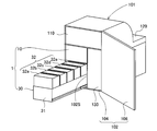
- FIG. 1 is a perspective view showing the appearance of an automated teller machine 101 equipped with a bill processing apparatus 1 as a paper sheet processing apparatus.
- the automated teller machine 101 is a device which is managed by a financial institution such as a bank and performs various transactions in accordance with the operation of the user (customer), for example, using a card, a bill, a statement slip as a medium and depositing the user. , Payment, transfer, etc.
- the automated teller machine 101 is stored in the storage space 102S of the housing 102.
- the case 102 is surrounded by a case body 104 and a door 106 for opening and closing the rear opening of the case body 104.
- the bill processing apparatus 1 is an apparatus disposed at the lower part of the automated teller machine 101 in the drawing for handling bills.
- the card and statement slip processing mechanism 110 is disposed at the top of the automated teller machine 101, is a device that processes a user's card, prints out a transaction slip, and outputs it.
- the customer operation unit 120 is a device for displaying and inputting the content of the transaction on the front of the device.
- the coin processing device 130 is disposed at the lower part of the automated teller machine 101 and is a device that handles coins.
- the automated teller machine 101 includes a power supply unit, a main control unit for controlling the entire automatic teller machine 101, and a main body to which each mechanism is connected by a line such as USB.
- a control unit (not shown) is also provided.
- the bill processing apparatus 1 includes a bill processing unit 10 (paper sheet processing unit) disposed in the upper part, a bill storage unit 30 (paper sheet storage unit) disposed in the lower part, and a control unit (control unit)
- the bill processing unit 10 and the bill storage unit 30 can be removed from the inside of the case 102 by opening the door 106 of the case 102.
- the mechanism for storing the bill processing unit 10 and the bill storage unit 30 will be described later.
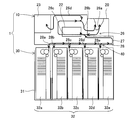
- FIG. 2 is a side sectional view showing a schematic configuration of the banknote handling apparatus 1.
- the bill processing unit 10 generally includes a mechanism necessary for exchanging bills with the user, and the bill depositing / dispensing port 20, the bill identifying unit 22, the temporary holding unit 23, and the bill among the respective units.
- An upper unit transport mechanism 26 for transporting, and a connection transport mechanism 27 for sending a bill from the upper unit transport mechanism 26 to the bill storage unit 30 are provided.
- the bill receiving / dispensing port 20 includes a deposit unit that allows the user to deposit and deposit bills, and a payment unit that dispenses bills.
- the bill validator 22 is a mechanism for discriminating whether or not a bill is a denomination, an authenticity, and a rejected bill, and outputting the discrimination result to the control unit. For example, an image obtained by scanning the bill It is a configuration using various information such as data, irregularities on the surface of a bill, magnetic characteristics, optical characteristics against ultraviolet light and the like.
- the rejected banknotes are banknotes that are incompatible due to the authenticity of the banknote, or banknotes that overlap or are broken and whose authenticity is unknown or the like.
- the temporary storage unit 23 is a mechanism for temporarily storing bills in the process of transporting the bills between the bill depositing / dispensing unit and the bill storage unit 30.
- the upper unit conveyance mechanism 26 is a mechanism that conveys a bill by rotational driving of a roller (not shown), and a deposit conveyance path 26a that conveys a bill inserted into the deposit unit of the bill deposit / withdrawal portion 20; It is equipped with a conveyance path 26b for paying out bills to a part, a conveyance path 26c for discrimination to make the bill identification part 22 pass the bill, and a conveyance path 26d for temporary stocking portion which carries the bill to the temporary stocking portion 23 ing.
- the discrimination conveyance path 26c, the temporary storage conveyance path, and the like are configured to be capable of being conveyed bidirectionally. Moreover, the gate etc.
- sensors for detecting passage of bills are disposed on the transport path, and detection signals of these sensors are sent to the control unit and used for judging passage of bills and presence / absence of bills. .
- the banknote storage unit 30 is provided with the storage body 31 and the banknote storage part 32 (paper sheet storage part).
- the storage body 31 is a box opened at the upper side, and the bill storage portion 32 is stored in the storage space.
- the bill storage unit 32 includes five bill storage units 32a to 32e, which have substantially the same configuration, and are disposed at the storage box forming a bill storage space for storing bills and at the top of the storage unit It has rollers and sensors.
- Each of the bill storage sections 32a to 32e stores the bills sent from the bill processing unit 10 in the bill storage space, and makes the stored bills bi-directionally with respect to the bill processing unit 10 by a transport mechanism such as a roller.
- banknote storage units 32a to 32e can be used so that the types of banknotes to be handled differ, and for example, the banknote storage for storing 10,000 yen, 5,000 yen, 1,000 yen, and 2,000 yen, or the above It can be used as a reject storage for storing reject bills.
- the connecting and conveying mechanism 27 is a secondary conveyance branched from the main conveyance path 28 and the main conveyance path 28 to the respective bill storage portions 32.
- the passages 28a to 28e are provided, and the banknotes are transported bidirectionally to the respective banknote storage portions 32a to 32e.
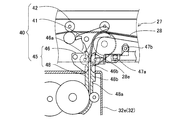
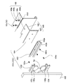
- FIG. 3 and 4 are cross-sectional views showing the vicinity of the branch point of the connecting and conveying mechanism 27.
- a branch connection mechanism 40 is disposed at each branch point of the connection and conveyance mechanism 27.
- the branch connection mechanism 40 includes a gate 41, a roller group 42 composed of a plurality of rollers for leading to the sub conveyance path 28e, and a connection mechanism 45.
- the gate 41 is an L-shaped member disposed at a branch point, and driven by a drive (not shown) (such as a solenoid) to copy the bill transported to the main transport path 28 into the roller group 42 and sub-steps
- the transport path 28e is switched to transport in both directions.
- the gate 41 (shown by a solid line) in FIG. 3 is a position for switching to the secondary conveyance path 28e, and the gate 41 indicated by a two-dot chain line is a position for transporting to the other secondary conveyance paths 28a to 28d.
- the connection mechanism 45 includes an upstream guide 46 and a downstream guide 48.
- the upstream guide portion 46 includes a guide main body 46 a.
- the guide main body 46a includes a guide groove 46b formed along the sub conveyance path 28a, and the bill is conveyed along the guide groove 46b.
- the downstream guide part 48 is provided with the guide main body 48a arrange
- the guide main body 48a has a guide groove 48b formed along the sub conveyance path 28e, and the bill is conveyed along the guide groove 48b.
- the upstream guide portion 46 and the downstream guide portion 48 are each formed in a comb-tooth shape, and their connection point, that is, the lower portion of the upstream guide portion 46 and the upper portion of the downstream guide portion 48 respectively enter each other between the combs,
- the guide grooves 46b and 48b formed by the unbroken wall surfaces constitute a part of the sub conveyance path 28e.
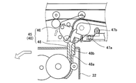
- the upstream guide portion 46 is rotatable by the rotation shaft 47a, and can rotate the rotation shaft 47a by receiving a driving force of a motor drive shaft 47b of a motor (not shown). Therefore, as shown in FIG. 4, the connection mechanism 45 moves with the upper portion of the downstream guide portion 48 when the power is not supplied to the motor or is reset, as shown in FIG.
- the connection mode (connection position) shown in FIG. 3 is established by the non-connection mode (non-connection position) where the overlapping portion disappears and power is supplied to the motor.
- the banknotes stored in the temporary storage unit 23 are separated and fed out one by one, and are further counted and identified by the banknote identification unit 22 via the discrimination conveyance path 26c, and the coupling conveyance mechanism 27 , And is transported from the coupling transport mechanism 27 to any of the bill storage sections 32 (32a to 32e) designated by the main body control section. This completes the deposit transaction.
- the banknotes are separated and fed one by one from the banknote storage unit 32 instructed by the main body control unit.
- the bill passes through the discrimination conveyance path 26c of the connection conveyance mechanism 27 and the upper unit conveyance mechanism 26, and after being discriminated and counted by the bill identification unit 22, the bill deposit / withdrawal port via the withdrawal conveyance path 26b.
- the delivery unit of the unit 20 is reached and provided to the customer. This completes the withdrawal transaction.
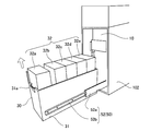
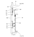
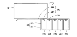
- FIG. 5 is a perspective view showing the bill processing unit 10 pulled out of the housing 102 through the unit guide mechanism 50.
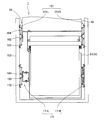
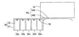
- FIG. 6 shows the bill storage unit 30 pulled out of the housing 102 through the unit guide mechanism 50.
- FIG. 7A is a schematic configuration view for explaining the unit guide mechanism 50.
- the unit guide mechanism 50 includes a first slide mechanism 151 and a second slide mechanism 171.
- the first slide mechanism 151 is disposed between both sides of the bill processing unit 10 and the inner wall of the housing 102, and is a mechanism for pulling out the bill processing unit 10 from the housing 102.
- the second slide mechanism 171 is disposed between both sides of the bill storage unit 30 and the inner wall of the housing 102, and is a mechanism for pulling out the bill storage unit 30 from the housing 102.
- the first slide mechanism 151 includes a left slide mechanism 151L disposed on the left side of the bill processing unit 10 in the figure and a right slide mechanism 151R disposed on the right side of the bill processing unit 10 in the figure. It is slidably supported horizontally with respect to 102.
- the second slide mechanism 171 includes a left slide mechanism 171L disposed on the left side of the bill storage unit 30 in the drawing and a right slide mechanism 171R disposed on the right side of the bill storage unit 30 in the drawing. It is slidably supported horizontally with respect to 102.
- FIG. 7B is an exploded perspective view of the left slide mechanism 151L of the first slide mechanism 151.
- the left slide mechanism 151L includes a first guide portion 152, a first guided portion 162, and a first connection mechanism 164.
- the first guide portion 152 includes a guide support upper frame 153, a guide support lower frame 154, and rails 155a and 155b in which a large number of rollers are disposed between the guide support upper frame 153 and the guide support lower frame 154. .
- a gap Sp for inserting the first guided portion 162 is formed between the rail 155a and the rail 155b.
- the upper guide support frame 153 and the lower guide support frame 154 are fixed to the inner wall of the housing 102 by fixing members 153 n and 154 n, respectively.
- the first guided portion 162 includes a guide base 162a formed in a rectangular shape in cross section and a guide piece 162b extended from an end of the guide base 162a.
- the guide base 162a is disposed in the gap Sp between the rail 155a and the rail 155b, and the guide piece 162b is pulled out by the rails 155a and 155b, whereby the guided member 162 is horizontal to the first guide portion 152. It is supported slidably in the direction.
- the first connection mechanism 164 is a mechanism for adjusting the horizontal position of the first guided portion 162 with respect to the outer wall of the bill processing unit 10, and includes a connection member 165 and a first distance adjustment portion 168. ing.
- the connecting member 165 includes a horizontal portion 166 and a vertical portion 167, and is formed in an L shape by being bent at a right angle. The end of the horizontal portion 166 is inserted into the slit 10d of the support plate 10c. The vertical portion 167 fixes the first guided portion 162 via the fixing member 162 n.
- FIG. 7C is a cross-sectional view for explaining the configuration around the first distance adjustment unit 168.
- the first distance adjusting portion 168 is a mechanism for movably connecting the bill processing unit 10 and the first guided portion 162 (FIG. 7B) in the horizontal direction relatively, and includes a long hole 10h formed in the support plate 10c. , A fastening hole 166h formed in the horizontal portion 166, a fixing member 169n which is a screw, and a spacer 169s.
- the fixing member 169n is screwed into the fastening hole 166h of the horizontal portion 166 through the hole of the spacer 169s, and the fixing member 169n and the spacer 169s are integrated with the connecting member 165.
- the elongated hole 10h is a hole having an inner diameter larger than the outer diameter of the spacer 169s in the arrow direction, and the spacer 169s and the connecting plate 165 do not contact each other even when the support plate 10c and the connecting member 165 move relatively horizontally. A gap Sp3 is secured between them. Therefore, the connecting member 165 is not restrained in the arrow direction (one side in the horizontal direction) with respect to the support plate 10c, and is connected after securing the movability.
- the right side slide mechanism 151R has the same configuration as the left side slide mechanism 151L without the first connection mechanism 164, and the bill processing unit 10 can slide against the inner wall of the housing 102 on the right side of the bill processing unit 10 in the figure.
- the bill processing unit 10 can slide against the inner wall of the housing 102 on the right side of the bill processing unit 10 in the figure.
- FIG. 7D is an exploded perspective view of the second slide mechanism 171.
- FIG. The second slide mechanism 171 is different in the configuration of the second connection mechanism 184 from the configuration of the first connection mechanism 164 (FIG. 7B) of the first slide mechanism 151.
- the second connection mechanism 184 is a mechanism for connecting the second guided portion 182 to the outer wall of the bill storage unit 30 and adjusting the horizontal position, and includes a first connection member 185 and a second connection member 186. , And a second distance adjustment unit 188.
- the first connection member 185 includes a vertical plate 185a and a horizontal plate 185b disposed in parallel from the upper and lower ends of the vertical plate 185a, which are integrally formed, and the vertical plate 185a stores the banknotes via the fixing member 185n. It is fixed to the storage body 31 of the unit 30.
- the second connection member 186 includes a vertical plate 186a and horizontal plates 186b arranged in parallel from the upper and lower ends of the vertical plate 186a, which are integrally formed, and guided by the vertical plate 186a via the fixing member 182n.
- the member 182 is fixed.
- the second distance adjustment unit 188 is a mechanism that intervenes between and connects the storage body 31 of the bill storage unit 30 and the second guided portion 182, and is formed on the horizontal plate 185b of the first connection member 185.
- the first connecting member 185 and the second connecting member 186 are movably connected through the elongated hole 185 h and the screw hole 186 h by overlapping the horizontal plate 185 b and the horizontal plate 186 b.
- the first connection member 185 and the second connection member 186 are movably connected in one horizontal direction by the same configuration as the first distance adjustment unit 168 described in FIG. 7C. .
- the right side slide mechanism 171R has the same configuration as the left side slide mechanism 171L without the second connection mechanism 184 (FIG. 7C), and the illustrated right side of the bill storage unit 30 is the inner wall of the housing 102 in the inner wall of the housing 102.
- the storage body 31 is movably supported.
- the door 106 of the case 102 is opened, and as shown in FIG. 5, by holding the handle 11a of the bill processing unit 10 and applying a force to the bill processing unit 10 in the front direction, The bill processing unit 10 can be pulled out via the unit guide mechanism 50.
- the bill processing unit 10 can be pulled out via the unit guide mechanism 50.
- FIG. 6 by grasping the handle 31a of the storage body 31, pulling out the storage body 31, and taking out the bill storage portion 32, it is possible to carry out a bill collection operation and a loading operation.
- FIG. 7E is an explanatory view for explaining the withdrawal operation of the bill processing unit 10 or the like of the bill processing apparatus 1. Due to the variation in the dimension in the width direction of the housing 102, a difference may occur in the movement direction in the sliding gaps Ls1 and Ls2, which are the gaps between the inner wall of the housing 102 and the outer walls of the bill processing unit 10 and the bill storage unit 30. .
- the difference between the slide gaps Ls1 and Ls2 is caused by the first and second guide portions 152 and 172 and the first and second guided portions 162 and 182 when the bill processing unit 10 or the bill storage unit 30 is pulled out or stored.
- the first distance adjustment unit 168 may not be a gap or a first guided
- the second distance adjustment unit 188 absorbs the difference in the sliding gap Ls2 between the housing 102 and the bill storage unit 30.
- the first and second guide portions 152 and 172 and the first and second guided portions 162, 172 absorb the difference between the sliding gaps Ls1 and Ls2 by the first and second distance adjusting portions 168 and 188.
- the increase in the frictional force generated at the time of sliding with 182 can be reduced, and therefore, the bill processing unit 10 and the bill storage unit 30 can be smoothly slid with respect to the housing 102 with a small operation force.
- the first connecting mechanism 164 is connected between the bill processing unit 10 and the guide.
- the present invention is not limited to this configuration, and between the housing 102 and the first guide portion 152. Even if it arranges, the difference of the clearance for sliding can be absorbed.
- long hole 10h was formed in the support plate 10c of the banknote processing unit 10, not only this but a banknote processing unit and banknote storage unit
- a long hole may be formed on the connecting member side as long as it can be movably connected in the horizontal direction with the guide portion or the guided portion.
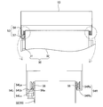
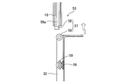
- FIG. 7F is an explanatory view for explaining the cooperation guide mechanism 53 for suspending and guiding the bill storage unit 32 of the bill storage unit 30 to the bill processing unit 10.
- FIG. 8 shows the bill storage unit 32 of the bill storage unit 30 from the bill processing unit 10. It is explanatory drawing explaining the cooperation guide mechanism 53 in the state which removed.
- the cooperation guide mechanism 53 suspends the plurality of bill storage portions 32 stored in the storage body 31 of the bill storage unit 30 with respect to the bill processing unit 10, and also the bill processing unit 10 and the bill storage unit 30. Is a mechanism that guides the movement of the bill storage unit 32 in the vertical direction and the horizontal direction when the bill holder moves relatively.
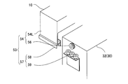
- the cooperation guide mechanism 53 includes a suspension mechanism 54 and a horizontal direction guide mechanism 57.
- the suspension mechanism 54 includes storage guide rails 54R and 54L fixed on both sides of the side wall of the bill processing unit 10, and a first roller 56 mounted on the upper side wall of the bill storage unit 32.
- the storage guide rails 54R, 54L are long members which are disposed over substantially the entire length of the bill processing unit 10 in the horizontal direction and suspend the bill storage portion 32.
- the storage guide rails 54R and the storage guide rails 54L are provided. And have different cross-sectional shapes.
- the storage guide rail 54L is bent upward from the end of the horizontal portion 54Lb, the rail base 54La provided downward from the side wall of the bill processing unit 10, the horizontal portion 54Lb bent from the lower end of the rail base 54La, and And the support standing portion 54Lc.
- the first roller 56 is rotatably supported on the upper side wall of both sides of the bill storage unit 32.
- the first roller 56 is in the form of a pulley having an inclined groove 56a inclined toward the center.
- the first roller 56 rolls on the storage guide rail 54L in a state where the support standing portion 54Lc of the storage guide rail 54L is inserted into the inclined groove 56a.
- the storage guide rail 54R includes a rail base 54Ra and a support horizontal portion 54Rb. The first roller 56 rolls on the storage guide rail 54R by being placed on the support horizontal portion 54Rb.
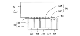
- FIG. 9 is an explanatory view for explaining the storage guide rail 54L side of the suspension mechanism 54 when the bill processing unit 10 and the bill storage unit 30 are viewed from the side. Since the storage guide rails 54R and 54L have substantially the same shape in the longitudinal direction, the storage guide rail 54L will be described as a representative.
- the storage guide rail 54L includes a general part 54A and guide inclined parts 54B formed on both sides of the general part 54A.
- the general part 54A is a linear shape having the cross-sectional shape shown in FIG. 7F as described above.
- the guide inclined portion 54B is inclined downward from the general portion 54A.
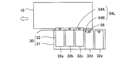
- FIG. 10 and 11 are explanatory views for explaining the positioning mechanism 55 of the general portion 54A of the storage guide rail 54L.
- a positioning mechanism 55 including a plurality of positioning portions 55a to 55e is formed on the upper portion of the general portion 54A.
- the positioning portions 55a to 55e are recesses for positioning each of the bill storage portions 32.
- each of the bill storage portions 32 can be connected to the connection mechanism 45 of the bill processing unit 10 (FIG. 3). Position with high accuracy.
- the horizontal distance L1 is longer than the distance L2 of the positioning portions 55b, 55c and 55d. Therefore, as shown in FIG.
- the positioning portion may be a protrusion or the like as long as the first roller 56 can be positioned in addition to the recess.
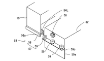
- FIG. 12 is a perspective view for explaining the horizontal guide mechanism 57
- FIG. 13 is an explanatory view of the vicinity of the horizontal guide mechanism 57 as viewed from above.
- the horizontal guide mechanism 57 is a mechanism for guiding the bill storage portion 32 in the left-right direction, and the second roller 59 mounted on one of the side walls of the bill storage portion 32 and the lower surface of the storage guide rail 54L.
- a fixed adjustment guide rail 58 The second roller 59 is provided with a fitting 59a attached to the side wall of the bill storage portion 32 in an L shape, and the flange 59b of the fitting 59a supports the second roller 59 so as to rotate on a horizontal surface.
- the adjustment guide rail 58 constitutes a guide groove 58a, and the second roller 59 is rotatably inserted into the guide groove 58a.
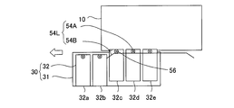
- FIGS. 14 to 23 are explanatory views for explaining the operation for pulling out or storing the bill processing unit 10 and the bill storage unit 30.
- A Withdrawal and Storage Operation of Banknote Processing Unit 10
- a -1 Drawout Operation of Banknote Processing Unit 10
- the banknote processing unit 10 and the banknote storage unit 30 are in the storage position.
- the five first rollers 56 mounted in the bill storage portion 32 are located in the general portion 54A of the storage guide rail 54R, as shown in FIG. It is positioned in the sections 55a to 55e.
- the bill storage portion 32 is at the lifting position away from the bottom of the storage body 31 by the distance Lv.
- connection mechanism 45 shown in FIG. 4 is set in the non-connection mode as shown in FIG. 4, and the lock mechanism 60 (see FIG. 24) is set in the non-locking position.
- the handle 11a (see FIG. 5) of the bill processing unit 10 is gripped and pulled by hand, the bill processing unit 10 moves in the arrow direction, as shown in FIG.
- the three first rollers 56 are positioned from the initial stage of operation to the positioning portions 55b to 55d.
- the second two first rollers 56 escape from the positioning portions 55a and 55e after having climbed up the inclined surface 55s of the above and finished climbing. Therefore, since the five first rollers 56 do not simultaneously escape from the positioning mechanism 55, the load (operation force) at the initial stage of operation can be reduced.
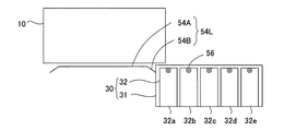
- bill processing unit 10 As shown in FIG. 15, as the bill processing unit 10 moves, the first roller 56 of the bill storage portion 32e is guided by the guide inclined portion 54B. As a result, the bill storage portion 32 e gradually descends and moves to the retracted position placed on the bottom surface of the storage body 31.
- the bill processing unit 10 is further moved through the states shown in FIGS. 16 and 17, the bill storage portions 32d, 32c, 32b, and 32b are sequentially guided by the guide inclined portion 54B and moved to the withdrawal position. Thereby, as shown in Drawing 18, bill processing unit 10 serves as a drawer position. By pulling out such a bill processing unit 10, it is possible to eliminate a jam or the like of the bill as described above.
- (A) -2 Storing Operation of Banknote Processing Unit 10
- the second roller 59 of the horizontal direction guide mechanism 57 strikes the end of the adjustment guide rail 58 and the adjustment guide rail 58 Is guided into the guide groove 58a of the Thereby, the bill storage unit 32 is aligned in the horizontal direction.
- the first roller 56 reaches the storage guide rail 54L (54R), as shown in FIG. 7F, one of the first rollers 56 rides on the supporting standing portion 54Lc of the storage guide rail 54L, (1) The roller 56 rides on the support horizontal portion 54Rb of the storage guide rail 54R. Then, as shown in FIG. 19, with the movement of the bill processing unit 10, the bill storage portion 32a is guided by the storage guide rail 54L (54R), and runs onto the general portion 54A from the guide inclined portion 54B.
- the bill storage unit 32b is lifted from the bill storage unit 32b by sequentially moving the first rollers 56 from the guide inclined portion 54B to the general portion 54A, and the connection mechanism 45 It is set so as to be directed to the transport path of FIG. 14 and passes through the states of FIG. 17, FIG. 16 and FIG. At this time, as shown in FIG. 10, the bill storage portion 32 is positioned when the first roller 56 reaches the positioning mechanism 55. Then, as shown in FIG. 3, by setting the connection mechanism 45 in the connection mode, the bill processing apparatus 1 can be driven.
- connection mechanism 45 is set to the non-connection mode and the lock mechanism 60 as in the case Set each to the non-locking position. Then, as shown in FIG. 20, when the grip 31a (see FIG. 5) of the bill storage unit 30 is grasped and pulled by hand, the bill storage unit 30 moves in the arrow direction. At this time, as shown in FIGS. 10 and 11, among the five first rollers 56 positioned in the positioning portions 55a to 55e, the three first rollers 56 are positioned from the initial stage of operation to the positioning portions 55b to 55d.
- the second two first rollers 56 escape from the positioning portions 55a and 55e after having climbed up the inclined surface 55s of the above and finished climbing. Therefore, since the five first rollers 56 do not simultaneously escape from the positioning mechanism 55, the load (operation force) at the initial stage of operation can be reduced.
- the bill storage portion 32a gradually descends following the inclination of the guide inclined portion 54B, It moves to the retracted position placed on the bottom of the storage body 31. Further, when the bill storage unit 30 moves through the states of FIG. 21, FIG. 22, and FIG. 23, the bill storage portions 32b, 32c, 32d, and 32e are sequentially guided by the guide inclined portion 54B and move to the withdrawal position. As a result, the bill storage unit 30 is in the withdrawal position. By pulling out the bill storage unit 30 in this manner, the bill storage unit 30 can be removed from the storage body 31 by being lifted above the respective bill storage portions 32.
- (B) -2 Storage Operation of Banknote Storage Unit 30
- a force is applied to the banknote storage unit 30 in the storage direction from the state of FIG.
- the horizontal guide mechanism 57 aligns in the horizontal direction.
- the first roller 56 rides on the storage guide rail 54L (54R), and along with the movement of the bill storage unit 30, the bill storage portion 32a is guided by the storage guide rail 54L (54R), and from the guide inclined portion 54B to the general part Get on to 54A.
- the bill storage portion 32a is sequentially lifted from the bill storage portion 32d by the movement of the first rollers 56 from the guide inclined portion 54B to the general portion 54A to the connection position. It moves to the storage position of FIG. At this time, as shown in FIG. 10, the bill storage portion 32 is positioned when the first roller 56 reaches the positioning mechanism 55. Then, as shown in FIG. 5, by setting the connection mechanism 45 in the connection mode, the bill processing apparatus 1 can be driven.
- the bill storage unit 30 can be linked by pulling it out through the first slide mechanism 151 of the unit guide mechanism 50 with respect to the housing 102.
- the guide mechanism 53 moves from the state in which the bill storage portion 32 is lifted with respect to the storage body 31 to the retracted position placed on the storage body 31.
- the cooperative guide mechanism 53 does not require a complicated configuration for retracting the bill storage portion 32 from the transport path of the connection mechanism 45 as described in the prior art, and the configuration is simplified.
- the horizontal direction guide mechanism 57 of the cooperative guide mechanism 53 performs the second operation when the banknote storage unit 32 is displaced in the left-right direction.
- the roller 59 strikes the end of the adjustment guide rail 58 and is guided into the guide groove 58 a of the adjustment guide rail 58.
- the bill storage portion 32 can be guided in the horizontal direction reliably.
- the positioning mechanism 55 of the cooperation guide mechanism 53 positions the bill storage portion 32 by dropping the first roller 56 to the positioning portions 55a to 55e of the recess respectively.
- connection reliability can be improved.
- the positioning portions 55a to 55e have different distances in the horizontal direction of the recess, and the first roller 56 does not separate from the positioning portion at the same time, so that the load (operating force) at the initial stage of operation can be reduced.
- the bill storage unit 32 is stored in the bill storage unit 32 by moving the first roller 56 at the top of the bill storage unit 32 on the storage guide rail 54L at the bottom of the bill processing unit 10 by the suspension mechanism 54.
- the bill storage unit 32 moves in the movement direction while being lifted from the above. Since one of the rollers of the suspension mechanism 54 is positioned in the width direction by the storage guide rail 54L, the suspension mechanism 54 is moved such that the slide gaps Ls1 and Ls2 are absorbed by the distance adjustment portion of the unit guide mechanism 50. Even if the bill storage unit 32 is positioned relative to the bill processing unit 10, the bill conveyance path between the bill processing unit 10 and the bill storage unit 32 is not misaligned, and there is no hindrance to the conveyance thereof. .
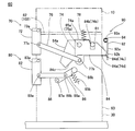
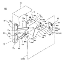
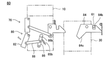
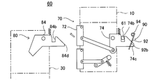
- FIG. 24 is a side view showing the locking mechanism 60
- FIG. 25 is an exploded perspective view of the locking mechanism 60.
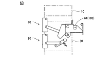
- the lock mechanism 60 is a mechanism for locking the drawer of the bill processing unit 10 and the bill storage unit 30.
- the lock mechanism 60 includes a lock pin 61 protruding from the inner wall of the housing 102, a first lock mechanism 70 for locking the bill processing unit 10, and a second lock mechanism 80 for locking the bill storage unit 30. And a cooperative lock mechanism 90.
- the first lock mechanism 70 includes a first operation portion 72, a first lock member 74, a link member 76, and a spring 78.
- the first operation unit 72 is rotatably supported by a support substrate 62 extended from the lower portion of the bill processing unit 10 about the rotation shaft 73 a, and operated by the user, the first lock member 74. Is a member for operating the lock position from the locked position to the unlocked position.
- the first lock member 74 includes a lock plate main body 74 a, is rotatably supported by the support substrate 62 by the rotation shaft 75 a, and is biased by a spring 78.
- the lock plate main body 74a has an engagement portion 74b at its upper portion which takes an engagement position engaging with the lock pin 61 and a non-locking position non-engagement, a stopper portion 74c formed at an end thereof, and a stopper An inclined surface 74d continuous to the portion 74c.
- the link member 76 is connected to the first operation portion 72 via the connection shaft 77a, and is connected to the first lock member 74 via the connection shaft 77b. Therefore, when the first operation portion 72 is operated in the direction of the arrow to rotate about the rotation shaft 73a, the first lock member 74 is biased by the spring 78 about the rotation shaft 75a via the link member 76. By rotating in opposition, the lock pin 61 engaged with the engaging portion 74b can be disengaged.
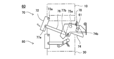
- the second lock mechanism 80 includes a second operation portion 82, a second lock member 84, a kicker member 86, a link member 88, a spring 85b, and a spring 85c.
- the second operation unit 82 is rotatably supported by the support substrate 62 about the rotation shaft 83a, and operated by the user to operate the second lock member 84 from the locked position to the unlocked position. It is a member of The second lock member 84 includes a lock plate main body 84a, is rotatably supported by the support substrate 63 on the side of the bill storage unit 30 about the rotation shaft 85a, and is biased by a spring 85b.
- the lock plate main body 84a has an engagement portion 84b which takes an engagement position engaged by the lock pin 61 and a non-engagement position where it does not engage, a pressing portion 84c which projects obliquely downward at its end, and the other end And an inclined surface 84e continuous with the stopper portion 84d.
- the kicker member 86 is connected to the second operation unit 82 via a link member 88.
- the kicker member 86 includes a rod-like kicker main body 86a and a kicker portion 86b formed at an end of the kicker main body 86a, and is rotatably supported around a rotation shaft 87a.
- the link member 88 connects the second operation portion 82 and the kicker member 86 by being rotatably connected to the connection shaft 89b via the second operation portion 82 and the connection shaft 89a. Therefore, when the second operation portion 82 is operated in the direction of the arrow and rotated about the rotation shaft 83a, the kicker member 86 receives the biasing force of the spring 85b about the rotation shaft 87a via the link member 88. Rotate against. When the kicker portion 86b of the kicker member 86 presses the pressing portion 84c of the second lock member 84, the second lock member 84 is rotated, and the lock pin 61 engaged with the engagement portion 84b is disengaged. can do.
- the cooperative lock mechanism 90 includes a movable plate 92 rotatably supported by a pivot shaft 93 a and a spring 94, and is biased by the spring 94.
- the movable plate 92 includes an abutting portion 92a and a stopper portion 92b formed by a hole.
- the contact portion 92 a restricts the rotation of the second lock member 84 by the stopper portion 84 d of the second lock member 84 coming into contact with the contact portion 92 a.
- the stopper portion 92 b regulates the rotation of the first lock member 74 by the insertion of the stopper portion 74 c.
- the rotation operation of the first operation unit 72 causes the first lock member 74 to rotate about the rotation shaft 75a.
- the engaging portion 74b of the first lock member 74 is disengaged from the lock pin 61, and the first lock mechanism 70 shifts from the lock position to the non-lock position.
- the kicker portion 86b is the second lock member.
- the second lock member 84 does not rotate because it does not hit the pressing portion 84 c of 84. Therefore, the engaging portion 84b does not come off from the lock pin 61, and the bill storage unit 30 maintains the lock position.
- the first lock mechanism 70 integrated with the bill processing unit 10 also moves in the same direction. Then, when the inclined surface 74d of the first lock member 74 abuts on the lock pin 61, the first lock member 74 rotates about the rotation shaft 75a against the biasing force of the spring 78, and the engagement portion 74b is locked. Engage 61 Thereafter, the biasing force of the spring 78 causes the first lock member 74 to rotate in the reverse direction. Thereby, the first lock mechanism 70 shifts to the lock position, and the withdrawal of the banknote handling unit 10 is restricted.
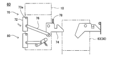
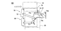
- FIG. 26 Withdrawal Operation of Banknote Storage Unit 30
- the bill processing unit 10 and the bill storage unit 30 are in the storage position.
- the second operation portion 82 rotates the rotation shaft. Rotate in the same direction around 83a.
- one end of the link member 88 is connected to the connecting shaft 89a, and the other end of the link member 88 is connected to the connecting shaft 89b.
- the kicker member 86 is rotated about the rotation shaft 87 a via the member 88.
- the kicker portion 86b of the kicker member 86 pushes the pressing portion 84c of the second lock member 84, and the second lock member 84 rotates about the rotation shaft 87a.
- the engaging portion 84b of the second lock member 84 is disengaged from the lock pin 61, and the second lock mechanism 80 shifts from the locked position to the unlocked position.
- the second lock member 84 and the like of the second lock mechanism 80 mounted on the bill storage unit 30 are also moved integrally. At this time, parts such as the first lock member 74 integrated with the bill processing unit 10 remain in the storage position. Then, as shown in FIG. 34, the second lock member 84 of the second lock mechanism 80 is returned by the spring force of the spring 85c, and the second operation portion 82 is returned to the original position by the spring 85b.
- the movable plate 92 of the cooperative lock mechanism 90 comes in contact with the stopper portion 84d of the second lock member 84, so that the second lock member 84 moves from the state in which the rotation is restricted. Therefore, it rotates by the spring force of the spring 94. Thereby, the stopper portion 92 b of the movable plate 92 enters the stopper portion 84 d of the second lock member 84, and the rotation of the second lock member 84 is restricted. Accordingly, the engaging portion 84 b of the second lock member 84 is engaged with the lock pin 61.
- the lock mechanism 60 pulls out only one of the bill processing unit 10 and the bill storage unit 30 from the housing 102 when both the bill processing unit 10 and the bill storage unit 30 are in the storage position. It works to make it impossible. That is, as shown in FIG. 30, when the bill processing unit 10 is pulled out, the kicker portion 86b of the kicker member 86 is the second lock member even if the second operation portion 82 of the second lock mechanism 80 is rotated. The second lock mechanism 80 maintains the lock position because the second lock member 84 can not be rotated without hitting the pressing portion 84 c of 84. On the other hand, as shown in FIG.
- the stopper portion 92b of the movable plate 92 of the cooperative lock mechanism 90 is engaged with the stopper portion 84d of the second lock member 84, and the first lock Since the rotation of the member 74 is restricted, the first lock member 74 can not be rotated even if the first operation part 72 of the first lock mechanism 70 is rotated, and the first lock mechanism 70 is locked. Maintain position.
- the lock mechanism 60 can not move the bill processing unit 10 and the bill storage unit 30 to the withdrawal position at the same time, thereby achieving the following effects.
- the bill processing unit 10 and the bill storage unit 30 are configured to be moved by rails arranged in the horizontal direction, for example, when the bill processing unit 10 is at the withdrawal position, the bill processing unit 10 is inclined and the bill storage unit 30 is inclined. It is easy for the distance between Even in such a state, in order to allow the bill storage unit 30 to be drawn out smoothly, a large interval is required so that the bill processing unit 10 does not interfere with the bill storage unit 30. A large interval requires a large moving distance to move the bill storage unit 30 to the connection point of the connection mechanism 45, and the connection configuration is complicated.
- the lock mechanism 60 since only one of the bill processing unit 10 and the bill storage unit 30 can be pulled out, the lock mechanism 60 does not need to have a large interval therebetween, and the connection mechanism 45 can be connected. It is possible to simplify the configuration and to guarantee a smooth withdrawal operation.
- the first and second locked engagement members are common to the first and second lock mechanisms, and the configuration can be simplified.
- the present invention is not limited to the above embodiment, and can be carried out in various modes without departing from the scope of the invention. For example, the following modifications are possible.
- the present invention can be applied to an apparatus that handles various types of paper sheets such as banknotes, cards, and paper (printed paper).
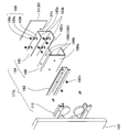
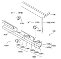
- FIG. 36 is an explanatory view for explaining the work of assembling the bill processing unit 10B to the first guided portion 162B.
- the present embodiment is characterized in the configuration of the first guided portion 162B.
- FIG. 36 is a partially broken perspective view showing a state before the bill processing unit 10B is assembled to the first guided portion 162B.
- the first guided portion 162B includes a guide base 162Ba and a guide piece 162Bb. In the guide base portion 162Ba, a fastening hole 162Bh and a positioning hole 163B are formed.
- the fastening holes 162Bh are composed of a first hole 162Bh1, a second hole 162Bh2 and a third hole 162Bh3 which are disposed at different positions in the vertical direction and obliquely.
- the fixing member 162Bn is inserted into one of the first to third holes 162Bh1 to 162Bh3 and is fastened to the fastening hole 167Bh.
- the positioning hole 163B is formed by one rectangular hole, and a first stepped portion 163Ba, a second stepped portion 163Bb and a third stepped portion 163Bc are respectively formed on the bottom of the hole.
- the first to third stepped portions 163Ba to 163Bc are formed in a step shape so that the positions in the vertical direction and the horizontal direction are different corresponding to the first to third holes 162Bh1 to 163Bh3.
- the first guided portion 162B is assembled to a first guide portion fixed to a housing (not shown), and the first guided portion 162B is pulled out of the first guide portion in advance. Further, the positioning member 163Bn is fixed in advance to the connecting member 165B of the first connecting mechanism 164B. Then, holding the bill processing unit 10B, the positioning member 163Bn is inserted into the positioning hole 163B. At this time, the positioning member 163Bn is placed on any of the first to third stepped portions 163Ba to 163Bc, and the bill processing unit 10B is temporarily placed on the first guided portion 162B.
- the fastening hole 162Bh is aligned with the fastening hole 167Bh, and the first to third steps are performed.
- the connecting member 165B is fixed to the first guided portion 162B by inserting the fixing member 162Bn into any of the holes 162Bh1 to 162Bh3 and screwing it into the fastening hole 167Bh.
- the bill processing unit 10B is temporarily placed on the first guided portion 162B temporarily via the positioning hole 163B and the positioning member 163Bn, and the fastening hole 162Bh is perpendicular to the fastening hole 167Bh. And because it can be adjusted in three levels in the horizontal direction, it is excellent in workability.
- the number of stages of the positioning holes 163B is not limited to three, and may be a large number of stages depending on alignment.
- Spring 80 second lock mechanism 82: second operation portion 83a: rotary shaft 84: second lock member 84a: lock plate main body 84b: engagement portion 84c: pressing portion 84d: stopper portion 84e: inclined surface 85a: rotation shaft 85b ... Spring 85c ... Spring 86 ... Kicker member 86a ... Kicker main body 86b ... Kicker portion 87a ... Rotation shaft 88 ... Link member 89a ... Coupling shaft 89b ... Coupling shaft 90 ... Cooperation lock mechanism 92 ... Movable plate 92a ... Contact portion 92b ... Stopper Section 93a ... rotation axis 94 ... spring 101 ... cash automatic transaction device 102 ... housing 102S ...
- First to third holes 162B first guided portion 162a: guide base portion 162b: guide piece 162n: fixed member 162Ba: guide base portion 162Bb: guide piece 162Bh: fastening hole 162Bn: fixed member 163B: positioning hole 163Ba: first 1 Part 163Ba, 163Bb, 163Bc ... 1st-3rd step part 163Bn ... Positioning member 164 ... 1st connection mechanism 164B ... 1st connection mechanism 165 ... Connection member 165B ... Connection member 166 ... Horizontal part 166h ... Fastening hole 167 ...
Abstract
A banknote processing unit (10) is provided with a housing (102), a banknote processing unit (10) and a banknote storage unit (30) which are housed within the housing (102), and a unit guide mechanism (50). The unit guide mechanism (50) is provided with a first guide unit (152) disposed horizontally along an inner wall of the housing (102), a first guided unit (162) disposed at an outer wall side of the banknote processing unit (10), and a first coupling mechanism (164). The first coupling mechanism (164) has a first distance adjusting unit (168) which modifies the distance between the first guided unit (162) and the banknote processing unit (10) when force in the horizontal direction is received as a result of movement of the banknote processing unit (10).
Description
この発明は、例えば紙幣などの紙葉類を処理する紙葉類処理装置に関する。
The present invention relates to a sheet processing apparatus for processing sheets such as banknotes.
この種の紙幣処理装置として、紙幣の入金取引や出金取引を行うATMやCDなどの現金自動取引装置が知られ、金融機関やコンビニエンスストア等の店舗に設置されている。例えば、現金自動取引装置に実装される紙幣処理装置は、特許文献1に記載されているように、利用者に出金紙幣を放出しもしくは投入された入金紙幣を一枚ずつ繰出すための紙幣入出金口と、入金もしくは出金紙幣を判別する紙幣判別部と、入金した紙幣を一旦収納する一時保留部と、入金紙幣を分別して収納・保管し出金紙幣等として繰出すための複数の紙幣収納部と、上記各部分を接続する紙幣搬送路とを備えている。
As this type of bill processing apparatus, cash automated teller machines, such as ATMs and CDs, which perform bill deposit and withdrawal transactions are known, and are installed in stores such as financial institutions and convenience stores. For example, as described in Patent Document 1, a bill processing apparatus mounted on an automatic teller machine is a bill for dispensing the deposited bills to the user or for dispensing the deposited bills inserted one by one. A deposit / withdrawal port, a bill discriminating section for discriminating deposited or dispensed bills, a temporary storage section for temporarily storing deposited bills, and a plurality of separated deposited and deposited bills for dispensing and storage as a deposited bill or the like It has a bill storage part and a bill conveyance way which connects the above-mentioned each part.
また、上記紙幣処理装置では、紙幣入出金口、紙幣判別部および一時保留部を一体に組み付けて上部ユニットを構成し、トレーに複数の紙幣収納部を組み付けて下部ユニットとし、これらを筐体に収納している。そして、筐体と上部ユニットおよび下部ユニットとの間にレールによるガイド機構を配置し、筐体から上部ユニットおよび下部ユニットとを引き出し可能に構成している。これにより、保守や紙幣の再装填、多金種化・大容量化に対応している。
Further, in the bill processing apparatus, the bill deposit / withdrawal port, the bill discriminating portion, and the temporary storage portion are integrally assembled to constitute an upper unit, and a plurality of bill storage portions are assembled to a tray to form a lower unit. I have stored it. Then, a guide mechanism by a rail is disposed between the housing and the upper unit and the lower unit, and the upper unit and the lower unit can be drawn out from the housing. This supports maintenance, reloading of banknotes, and increases in the number of types of money and capacity.
しかしながら上記筐体は、製造上のばらつきにより、1台毎に寸法が僅かに異なり易い。特に、上部ユニットや下部ユニットをスムーズに引き出すために、筐体と上部ユニットや下部ユニットとの水平方向の間隙に高い寸法精度が要求され、製造が面倒であるという課題があった。
However, due to manufacturing variations, the above-mentioned housings are likely to differ slightly in size from one unit to another. In particular, in order to pull out the upper unit and the lower unit smoothly, high dimensional accuracy is required in the horizontal gap between the casing and the upper unit and the lower unit, and there is a problem that the manufacturing is troublesome.
この発明は、上述した問題に鑑み、紙幣などの紙葉類を処理する紙幣ユニットを引き出しまたは収納する動作をスムーズに行なうことができるユニットガイド機構を備えた紙葉類処理装置を簡単な構成で実現する。
SUMMARY OF THE INVENTION In view of the problems described above, the present invention has a simple configuration with a sheet processing apparatus having a unit guide mechanism capable of smoothly performing an operation of pulling out or storing a bill unit that processes sheets such as bills. To realize.
本発明は、上述の課題の少なくとも一部を解決するためになされたものであり、以下の形態または適用例として実現することが可能である。
The present invention has been made to solve at least a part of the above-described problems, and can be realized as the following modes or application examples.
[適用例1]
適用例1は、投入または繰り出される紙葉類を判別し、該判別された紙葉類を分けて収納する紙幣ユニットと、該紙幣ユニットを収納する収納スペースを有する筐体と、上記筐体と上記紙幣ユニットとの水平方向のスライド用間隙に介在して上記紙幣ユニットを上記収納スペースから引き出しおよび上記収納スペースに収納するためにガイドするユニットガイド機構と、を備えた紙葉類処理装置であって、
上記ユニットガイド機構は、上記筐体の内壁に沿って水平方向に配置されたガイド部と、上記紙幣ユニットの外壁側に配置され上記ガイド部に沿って移動可能である被ガイド部と、上記筐体と上記ガイド部との連結または上記紙幣ユニットと上記被ガイド部との連結の少なくとも一方を行なう連結機構と、を備え、
上記連結機構は、上記紙幣ユニットの移動によって水平方向の力を受けたときに、上記ガイド部と筐体との距離または被ガイド部と紙幣ユニットとの距離を変える距離調節部を有する、紙葉類処理装置。 Application Example 1
Application Example 1 determines a paper sheet to be inserted or fed, and separates and stores the determined paper sheet, a case having a storage space for storing the bill unit, and the case A sheet processing apparatus comprising: a unit guide mechanism which is interposed in a horizontal slide gap with the bill unit and guides the bill unit out from the storage space and guides the bill unit to be stored in the storage space. ,
The unit guide mechanism includes: a guide portion disposed horizontally along the inner wall of the housing; a guided portion disposed on the outer wall side of the bill unit and movable along the guide portion; And a connection mechanism that performs at least one of connection between the body and the guide portion or connection between the bill unit and the guided portion.
The connection mechanism has a distance adjustment unit that changes the distance between the guide and the housing or the distance between the guided portion and the bill unit when receiving a force in the horizontal direction by the movement of the bill unit. Processing device.
適用例1にかかる紙葉類処理装置において、筐体の内壁と紙幣ユニットの外壁との間には、ユニットガイド機構が配置されている。ユニットガイド機構は、筐体の内壁に固定されたガイド部と、紙幣ユニット側に配置された被ガイド部とを備え、被ガイド部がガイド部に対して移動することにより、筐体の収納スペースから紙幣ユニットを引き出し、および収納スペースに収納する。
In the paper sheet processing apparatus according to the first application example, a unit guide mechanism is disposed between the inner wall of the housing and the outer wall of the bill unit. The unit guide mechanism includes a guide portion fixed to the inner wall of the housing and a guided portion disposed on the side of the bill unit, and the guided portion moves relative to the guide portion, thereby the storage space of the housing Draw out the bill unit from the bill and store it in the storage space.
また、ユニットガイド機構の連結機構は、上記紙幣ユニットと上記ガイド部との連結または上記紙幣ユニットと上記被ガイド部との連結の少なくとも一方を行ない、さらに、距離調節部により、上記紙幣ユニットの移動方向への移動によって水平方向の力を受けたときに、上記ガイド部と筐体との距離または被ガイド部と紙幣ユニットとの距離を変える。
In addition, the connection mechanism of the unit guide mechanism performs at least one of connection of the bill unit and the guide portion or connection of the bill unit and the guided portion, and the movement of the bill unit by the distance adjustment unit. When horizontal force is received by movement in the direction, the distance between the guide portion and the housing or the distance between the guided portion and the bill unit is changed.
こうした距離の調節により、以下のような作用効果を奏する。すなわち、筐体の水平方向の寸法のバラツキにより、筐体の内壁と紙幣ユニットの外壁との間に形成されるスライド用間隙に水平方向で差が生じることがある。こうしたスライド用間隙の差は、紙幣ユニットが移動するときにガイド部と被ガイド部との摩擦力の増大を招く。しかし、距離調節部は、連結機構が加わる水平方向の力を受けたときに、ガイド部と筐体との間隙または被ガイド部と紙幣ユニットとの距離を変えることにより、スライド用間隙の差を吸収する。このような距離調節部によるスライド用間隙の差を吸収する作用によって、ガイド部と被ガイド部とのスライド時に生じる摩擦力の増大を低減し、よって、紙幣ユニットを筐体に対して小さな操作力でスムーズにスライド動作させることができる。
By adjusting the distance, the following effects can be obtained. That is, due to the variation in the dimension in the horizontal direction of the housing, a difference may occur in the horizontal direction in the sliding gap formed between the inner wall of the housing and the outer wall of the bill unit. Such a difference in the slide gap causes an increase in the frictional force between the guide portion and the guided portion when the bill unit moves. However, when the distance adjustment unit receives a horizontal force applied by the connection mechanism, the difference between the slide gaps can be reduced by changing the distance between the guide and the housing or the distance between the guided and the bill unit. Absorb. Such a distance adjusting portion absorbs the difference in the sliding gap, thereby reducing the increase in the frictional force generated when the guide portion and the guided portion slide, and hence, a small operating force for the bill unit relative to the housing Can slide smoothly.
[適用例2]
適用例2において、上記紙幣ユニットは、
投入または繰り出される紙葉類を判別する紙葉類処理ユニットと、
上記判別された紙葉類を分けて収納する複数の紙葉類収納部と、該複数の紙葉類収納部を収納する収納体とを有し、上記紙幣処理ユニットの下方に配置された紙葉類収納ユニットと、
上記紙葉類処理ユニットと上記紙葉類収納ユニットとの間を接続する搬送路を介して上記紙葉類を上記紙葉類処理ユニットと上記紙葉類収納ユニットとの間で双方向に搬送する搬送機構と、
を備え、
上記ユニットガイド機構は、上記筐体と上記紙幣処理ユニットとの上記スライド用間隙に配置された第1スライド機構と、上記筐体と上記紙幣収納ユニットとの上記スライド用間隙に配置された第2スライド機構とを備えている、紙葉類処理装置。 Application Example 2
In Application Example 2, the bill unit is
A sheet processing unit for determining a sheet to be fed or fed;
A plurality of paper sheet storage units separately storing the determined paper sheets, and a storage body for storing the plurality of paper sheet storage units, and the paper disposed below the bill processing unit Leaf storage unit,
The paper sheet is bidirectionally conveyed between the paper sheet processing unit and the paper sheet storage unit via a conveyance path connecting the paper sheet processing unit and the paper sheet storage unit. The transport mechanism
Equipped with
The unit guide mechanism includes a first slide mechanism disposed in the slide gap between the housing and the bill processing unit, and a second slide mechanism disposed in the slide gap between the housing and the bill storage unit. A sheet processing apparatus comprising a slide mechanism.
[適用例3]
適用例3において、上記連結機構は、上記被ガイド部と上記紙幣ユニットとの外壁を連結する連結部材を備え、
上記距離調節部は、上記連結部材と上記紙幣ユニットの一方に固定される固定部材と、上記連結部材と上記紙幣ユニットの他方に形成され上記固定部材が挿入される長穴とを有し、上記固定部材が該長穴内を移動することで上記スライド用間隙を可変にするように構成した紙葉類処理装置。 Application Example 3
In Application Example 3, the connection mechanism includes a connection member that connects the outer wall of the guided portion and the bill unit.
The distance adjusting unit has a fixing member fixed to one of the connecting member and the bill unit, and a long hole formed in the other of the connecting member and the bill unit and into which the fixing member is inserted. A sheet processing apparatus, wherein the slide gap is made variable by moving a fixing member in the long hole.
[適用例4]
適用例4において、上記距離調節部は、上記紙幣ユニットに固定された第1連結部材と、上記被ガイド部に固定された第2連結部材とを備え、
上記距離調節部は、上記第1連結部材と上記第2連結部材の一方に固定される固定部材と、上記第1連結部材と第2連結部材の他方に形成され上記固定部材が挿入される長穴とを有し、上記固定部材が該長穴内を移動することで上記スライド用間隙を可変にするように構成した紙葉類処理装置。 Application Example 4
In the application example 4, the distance adjusting unit includes a first connecting member fixed to the bill unit and a second connecting member fixed to the guided portion.
The distance adjusting portion is formed on the other of the fixing member fixed to one of the first connecting member and the second connecting member, and the other of the first connecting member and the second connecting member, and the length to which the fixing member is inserted A sheet processing apparatus, comprising: a hole; and the fixing member moving in the long hole to make the slide gap variable.
[適用例5]
適用例5において、上記第2スライド機構は、上記収納体をスライド可能に支持するように構成し、
上記ユニットガイド機構は、上記紙幣処理ユニットに移動方向に配置された収納用ガイドレールと、上記紙幣収納部に設けられ上記収納用ガイドレールにガイドされる第1ローラとを有し、上記紙幣収納部を上記紙幣処理ユニットで吊り上げた状態にて上記第1ローラが収納用ガイドレールを移動するように構成された吊り下げ機構を備え、
上記吊り下げ機構は、上記収納用ガイドレールおよび上記第1ローラを紙幣処理ユニットの幅方向の両側にそれぞれ配置し、一方の第1ローラが幅方向に位置決めされて上記収納用ガイドレール上を移動し、他方の第1ローラが収納用ガイドレール上で幅方向に遊びを有して収納用ガイドレール上を移動するように構成された、紙葉類処理装置。 Application Example 5
In the application example 5, the second slide mechanism is configured to slidably support the storage body,
The unit guide mechanism has a storage guide rail arranged in the moving direction in the bill processing unit, and a first roller provided in the bill storage unit and guided by the storage guide rail, and the bill storage A suspension mechanism configured to move the first roller in the storage guide rail in a state where the portion is lifted by the bill processing unit,
The suspension mechanism arranges the storage guide rail and the first roller on both sides in the width direction of the bill processing unit, and one of the first rollers is positioned in the width direction to move on the storage guide rail A sheet processing apparatus, wherein the other first roller is configured to move on the storage guide rail with play in the width direction on the storage guide rail.
この適用例5の吊り下げ機構により、紙幣処理ユニットの下部の収納用ガイドレール上を紙幣収納部の上部の第1ローラが移動することで、紙幣収納部を収納体から吊り上げた状態にて、紙幣収納部が移動方向へ移動する。このような吊り下げ機構は、一方のローラが収納用ガイドレールで幅方向へ位置決めされているので、ユニットガイド機構の距離調節部によって距離が調節されても、紙幣収納部に紙幣処理ユニットに対して位置決めされ、紙幣処理ユニットと紙幣収納部との間の紙葉類の搬送路が位置ズレすることがなく、その搬送に支障がない。
In the state where the bill storage unit is lifted from the storage body by the first roller of the upper part of the bill storage unit moving on the storage guide rail of the lower part of the bill processing unit by the suspension mechanism of this application example 5; The bill storage unit moves in the moving direction. In such a suspension mechanism, one of the rollers is positioned in the width direction by the storage guide rail, so even if the distance is adjusted by the distance adjustment unit of the unit guide mechanism, the bill storage unit Therefore, the transport path of the paper sheet between the bill processing unit and the bill storage unit is not misaligned, and there is no hindrance to the transport.
(1) 現金自動取引装置101の概略構成
以下、本発明の一実施例について図面を用いて説明する。図1は紙葉類処理装置としての紙幣処理装置1を搭載した現金自動取引装置101の外観を示す斜視図である。現金自動取引装置101は、銀行などの金融機関によって管理され、利用者(顧客)の操作に応じて各種取引を行なう装置であり、例えば、カード、紙幣、明細票を媒体とし、利用者の預け入れ、支払い、振り込みなどの処理を行うものである。現金自動取引装置101は、筐体102の収納スペース102Sに収納されている。筐体102は、筐体本体104と筐体本体104の後部開口を開閉する扉106とで囲まれており、筐体102内に、紙幣処理装置1と、明細票処理機構110と、顧客操作部120と、硬貨処理装置130とが収納されている。紙幣処理装置1は、現金自動取引装置101の図示の下部に配置され、紙幣を取り扱う装置である。カード・明細票処理機構110は、現金自動取引装置101の上部に配置され、利用者のカードを処理し、取引明細票を印字して出力する装置である。顧客操作部120は、装置正面前方に取引の内容を表示および入力するための装置である。硬貨処理装置130は、現金自動取引装置101の下部に配置され、硬貨を取り扱う装置である。また、図示は省略しているが、現金自動取引装置101は、電源ユニットや、現金自動取引装置101の全体を制御するための本体制御ユニットや、各機構がUSB等の回線によって接続される本体制御部(図示省略)も備えている。 (1) Schematic Configuration ofAutomated Teller Machine 101 Hereinafter, an embodiment of the present invention will be described using the drawings. FIG. 1 is a perspective view showing the appearance of an automated teller machine 101 equipped with a bill processing apparatus 1 as a paper sheet processing apparatus. The automated teller machine 101 is a device which is managed by a financial institution such as a bank and performs various transactions in accordance with the operation of the user (customer), for example, using a card, a bill, a statement slip as a medium and depositing the user. , Payment, transfer, etc. The automated teller machine 101 is stored in the storage space 102S of the housing 102. The case 102 is surrounded by a case body 104 and a door 106 for opening and closing the rear opening of the case body 104. In the case 102, the bill processing apparatus 1, the statement slip processing mechanism 110, and the customer operation are provided. A unit 120 and a coin processing device 130 are housed. The bill processing apparatus 1 is an apparatus disposed at the lower part of the automated teller machine 101 in the drawing for handling bills. The card and statement slip processing mechanism 110 is disposed at the top of the automated teller machine 101, is a device that processes a user's card, prints out a transaction slip, and outputs it. The customer operation unit 120 is a device for displaying and inputting the content of the transaction on the front of the device. The coin processing device 130 is disposed at the lower part of the automated teller machine 101 and is a device that handles coins. Although not shown, the automated teller machine 101 includes a power supply unit, a main control unit for controlling the entire automatic teller machine 101, and a main body to which each mechanism is connected by a line such as USB. A control unit (not shown) is also provided.
以下、本発明の一実施例について図面を用いて説明する。図1は紙葉類処理装置としての紙幣処理装置1を搭載した現金自動取引装置101の外観を示す斜視図である。現金自動取引装置101は、銀行などの金融機関によって管理され、利用者(顧客)の操作に応じて各種取引を行なう装置であり、例えば、カード、紙幣、明細票を媒体とし、利用者の預け入れ、支払い、振り込みなどの処理を行うものである。現金自動取引装置101は、筐体102の収納スペース102Sに収納されている。筐体102は、筐体本体104と筐体本体104の後部開口を開閉する扉106とで囲まれており、筐体102内に、紙幣処理装置1と、明細票処理機構110と、顧客操作部120と、硬貨処理装置130とが収納されている。紙幣処理装置1は、現金自動取引装置101の図示の下部に配置され、紙幣を取り扱う装置である。カード・明細票処理機構110は、現金自動取引装置101の上部に配置され、利用者のカードを処理し、取引明細票を印字して出力する装置である。顧客操作部120は、装置正面前方に取引の内容を表示および入力するための装置である。硬貨処理装置130は、現金自動取引装置101の下部に配置され、硬貨を取り扱う装置である。また、図示は省略しているが、現金自動取引装置101は、電源ユニットや、現金自動取引装置101の全体を制御するための本体制御ユニットや、各機構がUSB等の回線によって接続される本体制御部(図示省略)も備えている。 (1) Schematic Configuration of
(2) 紙幣処理装置1の構成:
紙幣処理装置1は、上部に配置された紙幣処理ユニット10(紙葉類処理ユニット)と、下部に配置された紙幣収納ユニット30(紙葉類収納ユニット)と、両ユニットを制御する制御ユニット(図示省略)とを備えており、筐体102の扉106を開くことにより、紙幣処理ユニット10および紙幣収納ユニット30を筐体102内から取り出し可能に収納されている。なお、紙幣処理ユニット10および紙幣収納ユニット30の収納する機構については、後述する。 (2) Configuration of Banknote Processing Device 1:
Thebill processing apparatus 1 includes a bill processing unit 10 (paper sheet processing unit) disposed in the upper part, a bill storage unit 30 (paper sheet storage unit) disposed in the lower part, and a control unit (control unit) The bill processing unit 10 and the bill storage unit 30 can be removed from the inside of the case 102 by opening the door 106 of the case 102. The mechanism for storing the bill processing unit 10 and the bill storage unit 30 will be described later.
紙幣処理装置1は、上部に配置された紙幣処理ユニット10(紙葉類処理ユニット)と、下部に配置された紙幣収納ユニット30(紙葉類収納ユニット)と、両ユニットを制御する制御ユニット(図示省略)とを備えており、筐体102の扉106を開くことにより、紙幣処理ユニット10および紙幣収納ユニット30を筐体102内から取り出し可能に収納されている。なお、紙幣処理ユニット10および紙幣収納ユニット30の収納する機構については、後述する。 (2) Configuration of Banknote Processing Device 1:
The
図2は紙幣処理装置1の概略構成を示す側断面図である。
(2)-1 紙幣処理ユニット10の構成:
紙幣処理ユニット10は、概ね、利用者との紙幣の授受に必要な機構を備えており、紙幣入出金口部20と、紙幣識別部22と、一時保留部23と、紙幣を各部の間で搬送する上部ユニット搬送機構26と、上部ユニット搬送機構26からの紙幣を紙幣収納ユニット30へ送る連結搬送機構27とを備えている。
紙幣入出金口部20は、利用者が紙幣の預け入れを行なう入金部や紙幣の払い出しを行なう出金部などを備えている。紙幣識別部22は、紙幣の金種、真偽、および、リジェクト紙幣であるか否かを鑑別し、その鑑別結果を制御ユニットに出力する機構であり、例えば、紙幣をスキャンして得られる画像データ、紙幣の表面の凹凸形状、磁気特性、紫外線などに対する光学特性など種々の情報を利用した構成である。ここで、リジェクト紙幣は、紙幣の真偽により不適合な紙幣であるか、重なり合ったり、折れ曲がったりして真偽が不明な紙幣などをいう。一時保留部23は、紙幣入出金部と紙幣収納ユニット30との間の紙幣の搬送過程において、紙幣を一時的に保管する機構である。 FIG. 2 is a side sectional view showing a schematic configuration of thebanknote handling apparatus 1.
(2) -1 Configuration of Banknote Processing Unit 10:
Thebill processing unit 10 generally includes a mechanism necessary for exchanging bills with the user, and the bill depositing / dispensing port 20, the bill identifying unit 22, the temporary holding unit 23, and the bill among the respective units. An upper unit transport mechanism 26 for transporting, and a connection transport mechanism 27 for sending a bill from the upper unit transport mechanism 26 to the bill storage unit 30 are provided.
The bill receiving / dispensingport 20 includes a deposit unit that allows the user to deposit and deposit bills, and a payment unit that dispenses bills. The bill validator 22 is a mechanism for discriminating whether or not a bill is a denomination, an authenticity, and a rejected bill, and outputting the discrimination result to the control unit. For example, an image obtained by scanning the bill It is a configuration using various information such as data, irregularities on the surface of a bill, magnetic characteristics, optical characteristics against ultraviolet light and the like. Here, the rejected banknotes are banknotes that are incompatible due to the authenticity of the banknote, or banknotes that overlap or are broken and whose authenticity is unknown or the like. The temporary storage unit 23 is a mechanism for temporarily storing bills in the process of transporting the bills between the bill depositing / dispensing unit and the bill storage unit 30.
(2)-1 紙幣処理ユニット10の構成:
紙幣処理ユニット10は、概ね、利用者との紙幣の授受に必要な機構を備えており、紙幣入出金口部20と、紙幣識別部22と、一時保留部23と、紙幣を各部の間で搬送する上部ユニット搬送機構26と、上部ユニット搬送機構26からの紙幣を紙幣収納ユニット30へ送る連結搬送機構27とを備えている。
紙幣入出金口部20は、利用者が紙幣の預け入れを行なう入金部や紙幣の払い出しを行なう出金部などを備えている。紙幣識別部22は、紙幣の金種、真偽、および、リジェクト紙幣であるか否かを鑑別し、その鑑別結果を制御ユニットに出力する機構であり、例えば、紙幣をスキャンして得られる画像データ、紙幣の表面の凹凸形状、磁気特性、紫外線などに対する光学特性など種々の情報を利用した構成である。ここで、リジェクト紙幣は、紙幣の真偽により不適合な紙幣であるか、重なり合ったり、折れ曲がったりして真偽が不明な紙幣などをいう。一時保留部23は、紙幣入出金部と紙幣収納ユニット30との間の紙幣の搬送過程において、紙幣を一時的に保管する機構である。 FIG. 2 is a side sectional view showing a schematic configuration of the
(2) -1 Configuration of Banknote Processing Unit 10:
The
The bill receiving / dispensing
上部ユニット搬送機構26は、ローラ(図示省略)の回転駆動により紙幣を搬送する機構であり、紙幣入出金口部20の入金部に投入された紙幣を搬送する入金用搬送路26aと、出金部へ紙幣を繰り出す出金用搬送路26bと、紙幣識別部22に紙幣を通過させる鑑別用搬送路26cと、一時保留部23に対して紙幣を搬送する一時保留部用搬送路26dとを備えている。鑑別用搬送路26cおよび一時保管用搬送路などは、双方向に搬送可能に構成されている。また、搬送路の分岐箇所には、図示しないゲートなどが配置され、上述した搬送路における紙幣の搬送方向を切り替えるように構成されている。さらに、搬送路には、紙幣の通過などを検出するためのセンサが配置されており、これらのセンサの検出信号は、制御ユニットに送られ、紙幣の通過や紙幣の有無の判定に使用される。
The upper unit conveyance mechanism 26 is a mechanism that conveys a bill by rotational driving of a roller (not shown), and a deposit conveyance path 26a that conveys a bill inserted into the deposit unit of the bill deposit / withdrawal portion 20; It is equipped with a conveyance path 26b for paying out bills to a part, a conveyance path 26c for discrimination to make the bill identification part 22 pass the bill, and a conveyance path 26d for temporary stocking portion which carries the bill to the temporary stocking portion 23 ing. The discrimination conveyance path 26c, the temporary storage conveyance path, and the like are configured to be capable of being conveyed bidirectionally. Moreover, the gate etc. which are not shown in figure are arrange | positioned at the branch location of a conveyance path, and it is comprised so that the conveyance direction of the banknote in the conveyance path mentioned above may be switched. Furthermore, sensors for detecting passage of bills are disposed on the transport path, and detection signals of these sensors are sent to the control unit and used for judging passage of bills and presence / absence of bills. .
(2)-2 紙幣収納ユニット30の構成:
図1および図2において、紙幣収納ユニット30は、収納体31と、紙幣収納部32(紙葉類収納部)とを備えている。収納体31は、上方を開放した箱体であり、その収納スペースに紙幣収納部32を収納している。紙幣収納部32は、5個の紙幣収納部32a~32eを備えており、それらはほぼ同じ構成であり、紙幣を収納する紙幣収納スペースを形成する収納箱や、収納部の上部に配置されたローラやセンサなどを備えている。各々の紙幣収納部32a~32eは、紙幣処理ユニット10から送られた紙幣を紙幣収納スペースに収納するとともに、収納されている紙幣をローラなどの搬送機構により紙幣処理ユニット10に対して双方向へ紙幣を搬送する機構も備えている。このような紙幣収納部32a~32eは、扱う紙幣の種類が異なるように使用することができ、例えば、1万円、5千円、千円、2千円を収納する紙幣庫や、上述したリジェクト紙幣を収納するリジェクト庫として用いることができる。 (2) -2 Configuration of Banknote Storage Unit 30:
In FIG. 1 and FIG. 2, thebanknote storage unit 30 is provided with the storage body 31 and the banknote storage part 32 (paper sheet storage part). The storage body 31 is a box opened at the upper side, and the bill storage portion 32 is stored in the storage space. The bill storage unit 32 includes five bill storage units 32a to 32e, which have substantially the same configuration, and are disposed at the storage box forming a bill storage space for storing bills and at the top of the storage unit It has rollers and sensors. Each of the bill storage sections 32a to 32e stores the bills sent from the bill processing unit 10 in the bill storage space, and makes the stored bills bi-directionally with respect to the bill processing unit 10 by a transport mechanism such as a roller. It also has a mechanism for transporting banknotes. Such banknote storage units 32a to 32e can be used so that the types of banknotes to be handled differ, and for example, the banknote storage for storing 10,000 yen, 5,000 yen, 1,000 yen, and 2,000 yen, or the above It can be used as a reject storage for storing reject bills.
図1および図2において、紙幣収納ユニット30は、収納体31と、紙幣収納部32(紙葉類収納部)とを備えている。収納体31は、上方を開放した箱体であり、その収納スペースに紙幣収納部32を収納している。紙幣収納部32は、5個の紙幣収納部32a~32eを備えており、それらはほぼ同じ構成であり、紙幣を収納する紙幣収納スペースを形成する収納箱や、収納部の上部に配置されたローラやセンサなどを備えている。各々の紙幣収納部32a~32eは、紙幣処理ユニット10から送られた紙幣を紙幣収納スペースに収納するとともに、収納されている紙幣をローラなどの搬送機構により紙幣処理ユニット10に対して双方向へ紙幣を搬送する機構も備えている。このような紙幣収納部32a~32eは、扱う紙幣の種類が異なるように使用することができ、例えば、1万円、5千円、千円、2千円を収納する紙幣庫や、上述したリジェクト紙幣を収納するリジェクト庫として用いることができる。 (2) -2 Configuration of Banknote Storage Unit 30:
In FIG. 1 and FIG. 2, the
(2)-3 紙幣処理ユニット10と紙幣収納ユニット30との連携機構
図2において、連結搬送機構27は、主搬送路28と、主搬送路28から各々の紙幣収納部32に分岐した副搬送路28a~28eとを備え、各々の紙幣収納部32a~32eに対して双方向に紙幣を搬送している。 (2) -3 Cooperation mechanism between thebill processing unit 10 and the bill storage unit 30 In FIG. 2, the connecting and conveying mechanism 27 is a secondary conveyance branched from the main conveyance path 28 and the main conveyance path 28 to the respective bill storage portions 32. The passages 28a to 28e are provided, and the banknotes are transported bidirectionally to the respective banknote storage portions 32a to 32e.
図2において、連結搬送機構27は、主搬送路28と、主搬送路28から各々の紙幣収納部32に分岐した副搬送路28a~28eとを備え、各々の紙幣収納部32a~32eに対して双方向に紙幣を搬送している。 (2) -3 Cooperation mechanism between the
図3および図4は連結搬送機構27の分岐箇所の付近を示す断面図である。図3において、連結搬送機構27の分岐箇所には、分岐接続機構40がそれぞれ配設されている。ここでは、分岐接続機構40のうち、紙幣収納部32eに接続される副搬送路28eで説明する。分岐接続機構40は、ゲート41と、副搬送路28eへ導くための複数のローラからなるローラ群42と、接続機構45とを備えている。ゲート41は、分岐箇所に配置されたL字形の部材であり、図示しない駆動装置(ソレノイドなど)により駆動されることにより、主搬送路28に搬送される紙幣を、ローラ群42を倣いかつ副搬送路28eなどに対して双方向へ搬送するために切り換えられる。図3のゲート41(実線で示す)は、副搬送路28eへ切り換える位置であり、2点鎖線で示すゲート41は、他の副搬送路28a~28dへ搬送するための位置である。
3 and 4 are cross-sectional views showing the vicinity of the branch point of the connecting and conveying mechanism 27. FIG. In FIG. 3, a branch connection mechanism 40 is disposed at each branch point of the connection and conveyance mechanism 27. Here, in the branch connection mechanism 40, the sub conveyance path 28e connected to the bill storage portion 32e will be described. The branch connection mechanism 40 includes a gate 41, a roller group 42 composed of a plurality of rollers for leading to the sub conveyance path 28e, and a connection mechanism 45. The gate 41 is an L-shaped member disposed at a branch point, and driven by a drive (not shown) (such as a solenoid) to copy the bill transported to the main transport path 28 into the roller group 42 and sub-steps The transport path 28e is switched to transport in both directions. The gate 41 (shown by a solid line) in FIG. 3 is a position for switching to the secondary conveyance path 28e, and the gate 41 indicated by a two-dot chain line is a position for transporting to the other secondary conveyance paths 28a to 28d.
接続機構45は、上流ガイド部46と、下流ガイド部48とを備えている。上流ガイド部46は、ガイド本体46aを備えている。ガイド本体46aは、副搬送路28aに沿うように形成されたガイド溝46bを備え、このガイド溝46bに沿って紙幣が搬送される。下流ガイド部48は、紙幣収納部32側に配置されたガイド本体48aを備えている。ガイド本体48aは、副搬送路28eに沿うように形成されたガイド溝48bを備え、このガイド溝48bに沿って紙幣が搬送される。上流ガイド部46および下流ガイド部48は、それぞれ櫛歯状に形成されており、それらの接続箇所、つまり上流ガイド部46の下部と下流ガイド部48の上部とがそれぞれ櫛の間で互いに入り込み、切れ目のない壁面で形成されたガイド溝46b,48bによって副搬送路28eの一部を構成している。
The connection mechanism 45 includes an upstream guide 46 and a downstream guide 48. The upstream guide portion 46 includes a guide main body 46 a. The guide main body 46a includes a guide groove 46b formed along the sub conveyance path 28a, and the bill is conveyed along the guide groove 46b. The downstream guide part 48 is provided with the guide main body 48a arrange | positioned at the banknote accommodating part 32 side. The guide main body 48a has a guide groove 48b formed along the sub conveyance path 28e, and the bill is conveyed along the guide groove 48b. The upstream guide portion 46 and the downstream guide portion 48 are each formed in a comb-tooth shape, and their connection point, that is, the lower portion of the upstream guide portion 46 and the upper portion of the downstream guide portion 48 respectively enter each other between the combs, The guide grooves 46b and 48b formed by the unbroken wall surfaces constitute a part of the sub conveyance path 28e.
また、上流ガイド部46は、回転軸47aにより回動可能になっており、図示しないモータのモータ駆動軸47bの駆動力を受けて、回転軸47aを回動することができる。したがって、接続機構45は、モータに電源が供給されていない場合やリセットされている場合には、図4に示すように、上流ガイド部46が移動することで、下流ガイド部48の上部との重なる部分がなくなる非接続モード(非接続位置)となり、モータに電源が供給されることにより、図3に示す接続モード(接続位置)になる。
The upstream guide portion 46 is rotatable by the rotation shaft 47a, and can rotate the rotation shaft 47a by receiving a driving force of a motor drive shaft 47b of a motor (not shown). Therefore, as shown in FIG. 4, the connection mechanism 45 moves with the upper portion of the downstream guide portion 48 when the power is not supplied to the motor or is reset, as shown in FIG. The connection mode (connection position) shown in FIG. 3 is established by the non-connection mode (non-connection position) where the overlapping portion disappears and power is supplied to the motor.
(2)-4 紙幣処理装置1の概略動作
図2において、入金処理において、紙幣入出金口部20の入金部に投入された紙幣は、該紙幣入出金口部20で1枚毎に分離繰出しされ、入金用搬送路26a、出金用搬送路26bを通じて、紙幣識別部22へ搬送され、さらに一時保留部用搬送路26dを通じて一時保留部23へ搬送される。このとき、紙幣は、紙幣識別部22により、通過する紙幣を、計数識別される。一時保留部23で保留された紙幣は、取引金額が確定した後に、1枚毎に分離繰出しされ、さらに鑑別用搬送路26cを経由し、紙幣識別部22で再度計数識別され、連結搬送機構27に到達し、そして、連結搬送機構27から、本体制御部により指定された紙幣収納部32(32a~32e)のいずれかへ搬送される。これにより、入金取引が終了する。 (2) -4 Schematic Operation of theBanknote Processing Device 1 In FIG. 2, in the deposit process, the bills inserted into the depositing section of the bill depositing / dispensing port 20 are separated and delivered one by one by the bill dispensing / dispensing section 20. Then, the bill is conveyed to the bill discriminating section 22 through the deposit conveyance path 26a and the withdrawal conveyance path 26b, and is further conveyed to the temporary storage section 23 through the temporary storage section conveyance path 26d. At this time, the banknotes are counted and identified by the banknote recognition unit 22. After the transaction amount is fixed, the banknotes stored in the temporary storage unit 23 are separated and fed out one by one, and are further counted and identified by the banknote identification unit 22 via the discrimination conveyance path 26c, and the coupling conveyance mechanism 27 , And is transported from the coupling transport mechanism 27 to any of the bill storage sections 32 (32a to 32e) designated by the main body control section. This completes the deposit transaction.
図2において、入金処理において、紙幣入出金口部20の入金部に投入された紙幣は、該紙幣入出金口部20で1枚毎に分離繰出しされ、入金用搬送路26a、出金用搬送路26bを通じて、紙幣識別部22へ搬送され、さらに一時保留部用搬送路26dを通じて一時保留部23へ搬送される。このとき、紙幣は、紙幣識別部22により、通過する紙幣を、計数識別される。一時保留部23で保留された紙幣は、取引金額が確定した後に、1枚毎に分離繰出しされ、さらに鑑別用搬送路26cを経由し、紙幣識別部22で再度計数識別され、連結搬送機構27に到達し、そして、連結搬送機構27から、本体制御部により指定された紙幣収納部32(32a~32e)のいずれかへ搬送される。これにより、入金取引が終了する。 (2) -4 Schematic Operation of the
出金処理において、本体制御部より指示された紙幣収納部32から紙幣が1枚毎に分離繰出しされる。この紙幣は、連結搬送機構27、上部ユニット搬送機構26の鑑別用搬送路26cを通過し、紙幣識別部22にて識別計数された後に、出金用搬送路26bを経由して紙幣入出金口部20の出金部に到達し、顧客へ提供される。これにより、出金取引が終了する。
In the dispensing process, the banknotes are separated and fed one by one from the banknote storage unit 32 instructed by the main body control unit. The bill passes through the discrimination conveyance path 26c of the connection conveyance mechanism 27 and the upper unit conveyance mechanism 26, and after being discriminated and counted by the bill identification unit 22, the bill deposit / withdrawal port via the withdrawal conveyance path 26b. The delivery unit of the unit 20 is reached and provided to the customer. This completes the withdrawal transaction.
(3) ユニットガイド機構50
図5は紙幣処理ユニット10をユニットガイド機構50を介して筐体102から引き出した状態を示す斜視図、図6は紙幣収納ユニット30をユニットガイド機構50を介して筐体102から引き出した状態を示す斜視図、図7Aはユニットガイド機構50を説明する概略構成図である。図7Aにおいて、ユニットガイド機構50は、第1スライド機構151と、第2スライド機構171とを備えている。第1スライド機構151は、紙幣処理ユニット10の両側と筐体102の内壁との間に配置されており、紙幣処理ユニット10を筐体102から引き出すための機構である。第2スライド機構171は、紙幣収納ユニット30の両側と筐体102の内壁との間に配置されており、紙幣収納ユニット30を筐体102から引き出すための機構である。第1スライド機構151は、紙幣処理ユニット10の図示左側に配置された左側スライド機構151Lと、紙幣処理ユニット10の図示右側に配置された右側スライド機構151Rとを備え、紙幣処理ユニット10を筐体102に対して水平方向にスライド可能に支持している。第2スライド機構171は、紙幣収納ユニット30の図示左側に配置された左側スライド機構171Lと、紙幣収納ユニット30の図示右側に配置された右側スライド機構171Rとを備え、紙幣収納ユニット30を筐体102に対して水平方向にスライド可能に支持している。 (3)Unit guide mechanism 50
FIG. 5 is a perspective view showing thebill processing unit 10 pulled out of the housing 102 through the unit guide mechanism 50. FIG. 6 shows the bill storage unit 30 pulled out of the housing 102 through the unit guide mechanism 50. FIG. 7A is a schematic configuration view for explaining the unit guide mechanism 50. FIG. In FIG. 7A, the unit guide mechanism 50 includes a first slide mechanism 151 and a second slide mechanism 171. The first slide mechanism 151 is disposed between both sides of the bill processing unit 10 and the inner wall of the housing 102, and is a mechanism for pulling out the bill processing unit 10 from the housing 102. The second slide mechanism 171 is disposed between both sides of the bill storage unit 30 and the inner wall of the housing 102, and is a mechanism for pulling out the bill storage unit 30 from the housing 102. The first slide mechanism 151 includes a left slide mechanism 151L disposed on the left side of the bill processing unit 10 in the figure and a right slide mechanism 151R disposed on the right side of the bill processing unit 10 in the figure. It is slidably supported horizontally with respect to 102. The second slide mechanism 171 includes a left slide mechanism 171L disposed on the left side of the bill storage unit 30 in the drawing and a right slide mechanism 171R disposed on the right side of the bill storage unit 30 in the drawing. It is slidably supported horizontally with respect to 102.
図5は紙幣処理ユニット10をユニットガイド機構50を介して筐体102から引き出した状態を示す斜視図、図6は紙幣収納ユニット30をユニットガイド機構50を介して筐体102から引き出した状態を示す斜視図、図7Aはユニットガイド機構50を説明する概略構成図である。図7Aにおいて、ユニットガイド機構50は、第1スライド機構151と、第2スライド機構171とを備えている。第1スライド機構151は、紙幣処理ユニット10の両側と筐体102の内壁との間に配置されており、紙幣処理ユニット10を筐体102から引き出すための機構である。第2スライド機構171は、紙幣収納ユニット30の両側と筐体102の内壁との間に配置されており、紙幣収納ユニット30を筐体102から引き出すための機構である。第1スライド機構151は、紙幣処理ユニット10の図示左側に配置された左側スライド機構151Lと、紙幣処理ユニット10の図示右側に配置された右側スライド機構151Rとを備え、紙幣処理ユニット10を筐体102に対して水平方向にスライド可能に支持している。第2スライド機構171は、紙幣収納ユニット30の図示左側に配置された左側スライド機構171Lと、紙幣収納ユニット30の図示右側に配置された右側スライド機構171Rとを備え、紙幣収納ユニット30を筐体102に対して水平方向にスライド可能に支持している。 (3)
FIG. 5 is a perspective view showing the
図7Bは第1スライド機構151の左側スライド機構151Lを分解した斜視図である。左側スライド機構151Lは、第1ガイド部152と、第1被ガイド部162と、第1連結機構164とを備えている。第1ガイド部152は、ガイド支持上枠153と、ガイド支持下枠154と、ガイド支持上枠153とガイド支持下枠154との間にローラを多数配置したレール155a,155bとを備えている。レール155aとレール155bとの間には、第1被ガイド部162を挿入するための間隙Spが形成されている。ガイド支持上枠153およびガイド支持下枠154は、固定部材153n,154nによりそれぞれ筐体102の内壁に固定されている。
7B is an exploded perspective view of the left slide mechanism 151L of the first slide mechanism 151. FIG. The left slide mechanism 151L includes a first guide portion 152, a first guided portion 162, and a first connection mechanism 164. The first guide portion 152 includes a guide support upper frame 153, a guide support lower frame 154, and rails 155a and 155b in which a large number of rollers are disposed between the guide support upper frame 153 and the guide support lower frame 154. . A gap Sp for inserting the first guided portion 162 is formed between the rail 155a and the rail 155b. The upper guide support frame 153 and the lower guide support frame 154 are fixed to the inner wall of the housing 102 by fixing members 153 n and 154 n, respectively.
第1被ガイド部162は、断面矩形に形成されたガイド基部162aと、ガイド基部162aの端部から延設されたガイド片162bとを備えている。ガイド基部162aがレール155aとレール155bとの間隙Spに配置されるとともに、ガイド片162bがレール155a,155bにより抜止めされることにより、被ガイド部材162は、第1ガイド部152に対して水平方向にスライド可能に支持されている。
The first guided portion 162 includes a guide base 162a formed in a rectangular shape in cross section and a guide piece 162b extended from an end of the guide base 162a. The guide base 162a is disposed in the gap Sp between the rail 155a and the rail 155b, and the guide piece 162b is pulled out by the rails 155a and 155b, whereby the guided member 162 is horizontal to the first guide portion 152. It is supported slidably in the direction.
第1連結機構164は、紙幣処理ユニット10の外壁に対して第1被ガイド部162の水平方向の位置を調節するための機構であり、連結部材165と、第1距離調節部168とを備えている。連結部材165は、水平部166と、垂直部167とを備え、直角に折曲されることによりL字形に形成されている。水平部166の端部は、支持板10cのスリット10dに挿入されている。垂直部167は、固定部材162nを介して第1被ガイド部162を固定している。
The first connection mechanism 164 is a mechanism for adjusting the horizontal position of the first guided portion 162 with respect to the outer wall of the bill processing unit 10, and includes a connection member 165 and a first distance adjustment portion 168. ing. The connecting member 165 includes a horizontal portion 166 and a vertical portion 167, and is formed in an L shape by being bent at a right angle. The end of the horizontal portion 166 is inserted into the slit 10d of the support plate 10c. The vertical portion 167 fixes the first guided portion 162 via the fixing member 162 n.
図7Cは第1距離調節部168の周辺の構成を説明する断面図である。第1距離調節部168は、紙幣処理ユニット10と第1被ガイド部162(図7B)とを相対的に水平方向へ可動に連結する機構であり、支持板10cに形成された長穴10hと、水平部166に形成された締結用穴166hと、ネジである固定部材169nと、スペーサ169sとを備えている。固定部材169nは、スペーサ169sの穴を貫通して、水平部166の締結用穴166hにネジ止めされ、固定部材169nおよびスペーサ169sは、連結部材165と一体になっている。長穴10hは、矢印方向にスペーサ169sの外径より内径が大きい穴であり、また、支持板10cと連結部材165とが相対的に水平方向に移動しても、接触しないようにスペーサ169sとの間に間隙Sp3を確保している。よって、連結部材165は、支持板10cに対して矢印方向(水平方向の一方)に拘束されておらず、可動性を確保した上で連結されている。
FIG. 7C is a cross-sectional view for explaining the configuration around the first distance adjustment unit 168. As shown in FIG. The first distance adjusting portion 168 is a mechanism for movably connecting the bill processing unit 10 and the first guided portion 162 (FIG. 7B) in the horizontal direction relatively, and includes a long hole 10h formed in the support plate 10c. , A fastening hole 166h formed in the horizontal portion 166, a fixing member 169n which is a screw, and a spacer 169s. The fixing member 169n is screwed into the fastening hole 166h of the horizontal portion 166 through the hole of the spacer 169s, and the fixing member 169n and the spacer 169s are integrated with the connecting member 165. The elongated hole 10h is a hole having an inner diameter larger than the outer diameter of the spacer 169s in the arrow direction, and the spacer 169s and the connecting plate 165 do not contact each other even when the support plate 10c and the connecting member 165 move relatively horizontally. A gap Sp3 is secured between them. Therefore, the connecting member 165 is not restrained in the arrow direction (one side in the horizontal direction) with respect to the support plate 10c, and is connected after securing the movability.
図7Aにおいて、右側スライド機構151Rは、第1連結機構164がない左側スライド機構151Lと同じ構成であり、紙幣処理ユニット10の図示右側で筐体102の内壁に対して紙幣処理ユニット10をスライド可能に支持している。
In FIG. 7A, the right side slide mechanism 151R has the same configuration as the left side slide mechanism 151L without the first connection mechanism 164, and the bill processing unit 10 can slide against the inner wall of the housing 102 on the right side of the bill processing unit 10 in the figure. In favor of
図7Dは第2スライド機構171を分解した斜視図である。第2スライド機構171は、第2連結機構184の構成が第1スライド機構151の第1連結機構164(図7B)の構成と異なっている。
7D is an exploded perspective view of the second slide mechanism 171. FIG. The second slide mechanism 171 is different in the configuration of the second connection mechanism 184 from the configuration of the first connection mechanism 164 (FIG. 7B) of the first slide mechanism 151.
第2連結機構184は、第2被ガイド部182を紙幣収納ユニット30の外壁と連結するとともに水平方向の位置を調節するための機構であり、第1連結部材185と、第2連結部材186と、第2距離調節部188とを備えている。第1連結部材185は、垂直板185aと、垂直板185aの上下端から平行に配置された水平板185bとを備え、これらが一体に形成され、垂直板185aで固定部材185nを介して紙幣収納ユニット30の収納体31に固定されている。第2連結部材186は、垂直板186aと、垂直板186aの上下端から平行に配置された水平板186bとを備え、これらが一体に形成され、垂直板186aで固定部材182nを介して被ガイド部材182を固定している。第2距離調節部188は、紙幣収納ユニット30の収納体31と第2被ガイド部182との間に介在してこれらを連結する機構であり、第1連結部材185の水平板185bに形成された長穴185hと、第2連結部材186の水平板186bに形成されたネジ穴186hと、固定部材189nと、スペーサ189sとを備えている。第1連結部材185と第2連結部材186とは、水平板185bと水平板186bとが重ねられて、固定部材189nが長穴185hおよびネジ穴186hを貫通して可動に連結されている。第2距離調節部188は、図7Cで説明した第1距離調節部168と同様な構成により、第1連結部材185と第2連結部材186とが水平方向の一方向へ可動に連結されている。
The second connection mechanism 184 is a mechanism for connecting the second guided portion 182 to the outer wall of the bill storage unit 30 and adjusting the horizontal position, and includes a first connection member 185 and a second connection member 186. , And a second distance adjustment unit 188. The first connection member 185 includes a vertical plate 185a and a horizontal plate 185b disposed in parallel from the upper and lower ends of the vertical plate 185a, which are integrally formed, and the vertical plate 185a stores the banknotes via the fixing member 185n. It is fixed to the storage body 31 of the unit 30. The second connection member 186 includes a vertical plate 186a and horizontal plates 186b arranged in parallel from the upper and lower ends of the vertical plate 186a, which are integrally formed, and guided by the vertical plate 186a via the fixing member 182n. The member 182 is fixed. The second distance adjustment unit 188 is a mechanism that intervenes between and connects the storage body 31 of the bill storage unit 30 and the second guided portion 182, and is formed on the horizontal plate 185b of the first connection member 185. A long hole 185 h, a screw hole 186 h formed in the horizontal plate 186 b of the second connecting member 186, a fixing member 189 n, and a spacer 189 s. The first connecting member 185 and the second connecting member 186 are movably connected through the elongated hole 185 h and the screw hole 186 h by overlapping the horizontal plate 185 b and the horizontal plate 186 b. In the second distance adjustment unit 188, the first connection member 185 and the second connection member 186 are movably connected in one horizontal direction by the same configuration as the first distance adjustment unit 168 described in FIG. 7C. .
図7Aにおいて、右側スライド機構171Rは、第2連結機構184(図7C)がない左側スライド機構171Lと同じ構成であり、紙幣収納ユニット30の図示右側を筐体102の内壁で紙幣収納ユニット30の収納体31を移動可能に支持している。
In FIG. 7A, the right side slide mechanism 171R has the same configuration as the left side slide mechanism 171L without the second connection mechanism 184 (FIG. 7C), and the illustrated right side of the bill storage unit 30 is the inner wall of the housing 102 in the inner wall of the housing 102. The storage body 31 is movably supported.
したがって、図1に示すように、筐体102の扉106を開いて、図5に示すように、紙幣処理ユニット10の把手11aで掴んで紙幣処理ユニット10に手前方向に力を加えることにより、ユニットガイド機構50を介して、紙幣処理ユニット10を引き出すことができる。例えば、図5に示す扉106を開くことにより、紙幣のジャムを解消することができる。また、図6に示すように、収納体31の把手31aを掴んで、収納体31を引き出し、紙幣収納部32を取り出すことにより紙幣の回収作業や装填作業を行なうことができる。
Therefore, as shown in FIG. 1, the door 106 of the case 102 is opened, and as shown in FIG. 5, by holding the handle 11a of the bill processing unit 10 and applying a force to the bill processing unit 10 in the front direction, The bill processing unit 10 can be pulled out via the unit guide mechanism 50. For example, by opening the door 106 shown in FIG. 5, it is possible to eliminate the jam of the bill. Further, as shown in FIG. 6, by grasping the handle 31a of the storage body 31, pulling out the storage body 31, and taking out the bill storage portion 32, it is possible to carry out a bill collection operation and a loading operation.
また、紙幣処理ユニット10を筐体102から引き出すまたは収納する際に、第1および第2連結機構164,184は、紙幣処理ユニット10および紙幣収納ユニット30との水平方向への距離の調節により、以下のような作用効果を奏する。図7Eは紙幣処理装置1の紙幣処理ユニット10などの引き出し動作を説明する説明図である。筐体102の幅方向の寸法のバラツキにより、筐体102の内壁と紙幣処理ユニット10および紙幣収納ユニット30の外壁との間隙であるスライド用間隙Ls1,Ls2に移動方向で差が生じることがある。こうしたスライド用間隙Ls1,Ls2の差は、紙幣処理ユニット10または紙幣収納ユニット30の引き出しまたは収納する際に、第1および第2ガイド部152,172と第1および第2被ガイド部162,182との摩擦力の増大を招く。しかし、第1距離調節部168は、第1連結機構164が加わる水平方向の力を受けたときに、図7Cに示すように、第1ガイド部152と筐体102と間隙または第1被ガイド部162と紙幣処理ユニット10の距離を変えることにより、スライド用間隙Ls1の差を吸収する。また、第2距離調節部188も同様に、筐体102と紙幣収納ユニット30とのスライド用間隙Ls2の差を吸収する。このような第1および第2距離調節部168,188によるスライド用間隙Ls1,Ls2の差を吸収する作用によって、第1および第2ガイド部152,172と第1および第2被ガイド部162,182とのスライド時に生じる摩擦力の増大を低減し、よって、紙幣処理ユニット10および紙幣収納ユニット30を筐体102に対して小さな操作力でスムーズなスライド動作させることができる。
Further, when the bill processing unit 10 is pulled out or stored from the housing 102, the first and second connection mechanisms 164 and 184 adjust the distance in the horizontal direction between the bill processing unit 10 and the bill storage unit 30. The following effects are achieved. FIG. 7E is an explanatory view for explaining the withdrawal operation of the bill processing unit 10 or the like of the bill processing apparatus 1. Due to the variation in the dimension in the width direction of the housing 102, a difference may occur in the movement direction in the sliding gaps Ls1 and Ls2, which are the gaps between the inner wall of the housing 102 and the outer walls of the bill processing unit 10 and the bill storage unit 30. . The difference between the slide gaps Ls1 and Ls2 is caused by the first and second guide portions 152 and 172 and the first and second guided portions 162 and 182 when the bill processing unit 10 or the bill storage unit 30 is pulled out or stored. Cause an increase in friction with the However, when the first distance adjustment unit 168 receives a horizontal force applied by the first connection mechanism 164, as shown in FIG. 7C, the first distance adjustment unit 168 may not be a gap or a first guided By changing the distance between the portion 162 and the bill processing unit 10, the difference in the sliding gap Ls1 is absorbed. Similarly, the second distance adjustment unit 188 absorbs the difference in the sliding gap Ls2 between the housing 102 and the bill storage unit 30. The first and second guide portions 152 and 172 and the first and second guided portions 162, 172 absorb the difference between the sliding gaps Ls1 and Ls2 by the first and second distance adjusting portions 168 and 188. The increase in the frictional force generated at the time of sliding with 182 can be reduced, and therefore, the bill processing unit 10 and the bill storage unit 30 can be smoothly slid with respect to the housing 102 with a small operation force.
なお、上記実施例では、第1連結機構164を紙幣処理ユニット10と被ガイドとの間の連結した構成について説明したが、これに限らず、筐体102と第1ガイド部152との間に配置しても、スライド用間隙の差を吸収できる。
In the above embodiment, the first connecting mechanism 164 is connected between the bill processing unit 10 and the guide. However, the present invention is not limited to this configuration, and between the housing 102 and the first guide portion 152. Even if it arranges, the difference of the clearance for sliding can be absorbed.
図7Cに示すように、第1連結機構164の第1距離調節部168において、紙幣処理ユニット10の支持板10cに長穴10hを形成したが、これに限らず、紙幣処理ユニットや紙幣収納ユニットとガイド部または被ガイド部とを水平方向に移動可能に連結できる構成であれば、連結部材側に長穴を形成してもよい。
As shown to FIG. 7C, in the 1st distance adjustment part 168 of the 1st connection mechanism 164, although long hole 10h was formed in the support plate 10c of the banknote processing unit 10, not only this but a banknote processing unit and banknote storage unit A long hole may be formed on the connecting member side as long as it can be movably connected in the horizontal direction with the guide portion or the guided portion.
(4) 連携ガイド機構53
図7Fは紙幣処理ユニット10に紙幣収納ユニット30の紙幣収納部32を吊り下げてガイドする連携ガイド機構53を説明する説明図、図8は紙幣処理ユニット10から紙幣収納ユニット30の紙幣収納部32を外した状態で連携ガイド機構53を説明する説明図である。図7Fにおいて、連携ガイド機構53は、紙幣収納ユニット30の収納体31に収納された複数の紙幣収納部32を紙幣処理ユニット10に対して吊り下げるとともに、紙幣処理ユニット10と紙幣収納ユニット30とが相対的に移動したときに、紙幣収納部32の上下方向および水平方向への移動をガイドする機構である。連携ガイド機構53は、吊り下げ機構54と、水平方向ガイド機構57とを備えている。 (4)Cooperation guide mechanism 53
FIG. 7F is an explanatory view for explaining thecooperation guide mechanism 53 for suspending and guiding the bill storage unit 32 of the bill storage unit 30 to the bill processing unit 10. FIG. 8 shows the bill storage unit 32 of the bill storage unit 30 from the bill processing unit 10. It is explanatory drawing explaining the cooperation guide mechanism 53 in the state which removed. In FIG. 7F, the cooperation guide mechanism 53 suspends the plurality of bill storage portions 32 stored in the storage body 31 of the bill storage unit 30 with respect to the bill processing unit 10, and also the bill processing unit 10 and the bill storage unit 30. Is a mechanism that guides the movement of the bill storage unit 32 in the vertical direction and the horizontal direction when the bill holder moves relatively. The cooperation guide mechanism 53 includes a suspension mechanism 54 and a horizontal direction guide mechanism 57.
図7Fは紙幣処理ユニット10に紙幣収納ユニット30の紙幣収納部32を吊り下げてガイドする連携ガイド機構53を説明する説明図、図8は紙幣処理ユニット10から紙幣収納ユニット30の紙幣収納部32を外した状態で連携ガイド機構53を説明する説明図である。図7Fにおいて、連携ガイド機構53は、紙幣収納ユニット30の収納体31に収納された複数の紙幣収納部32を紙幣処理ユニット10に対して吊り下げるとともに、紙幣処理ユニット10と紙幣収納ユニット30とが相対的に移動したときに、紙幣収納部32の上下方向および水平方向への移動をガイドする機構である。連携ガイド機構53は、吊り下げ機構54と、水平方向ガイド機構57とを備えている。 (4)
FIG. 7F is an explanatory view for explaining the
(4)-1 吊り下げ機構54
吊り下げ機構54は、紙幣処理ユニット10の側壁の両側に固定された収納用ガイドレール54R,54Lと、紙幣収納部32の上部の側壁に装着された第1ローラ56とを備えている。収納用ガイドレール54R,54Lは、紙幣処理ユニット10の水平方向のほぼ全長に渡って配置され、紙幣収納部32を吊り下げる長尺部材であり、収納用ガイドレール54Rと、収納用ガイドレール54Lとで異なった断面形状になっている。収納用ガイドレール54Lは、紙幣処理ユニット10の側壁から下方に設けられたレール基部54Laと、レール基部54Laの下端から折曲された水平部54Lbと、水平部54Lbの端部から上方へ折曲された支持立設部54Lcとを備えている。第1ローラ56は、紙幣収納部32の両側の側壁上部にそれぞれ回転可能に支持されている。第1ローラ56は、中央に向けて傾斜した傾斜溝56aを有するプーリ形状である。第1ローラ56は、傾斜溝56aに収納用ガイドレール54Lの支持立設部54Lcが挿入された状態にて、収納用ガイドレール54L上を転動する。一方、収納用ガイドレール54Rは、レール基部54Raと、支持水平部54Rbとを備えている。第1ローラ56は、支持水平部54Rbに載置されることで、収納用ガイドレール54R上を転動する。 (4) -1Suspension mechanism 54
Thesuspension mechanism 54 includes storage guide rails 54R and 54L fixed on both sides of the side wall of the bill processing unit 10, and a first roller 56 mounted on the upper side wall of the bill storage unit 32. The storage guide rails 54R, 54L are long members which are disposed over substantially the entire length of the bill processing unit 10 in the horizontal direction and suspend the bill storage portion 32. The storage guide rails 54R and the storage guide rails 54L are provided. And have different cross-sectional shapes. The storage guide rail 54L is bent upward from the end of the horizontal portion 54Lb, the rail base 54La provided downward from the side wall of the bill processing unit 10, the horizontal portion 54Lb bent from the lower end of the rail base 54La, and And the support standing portion 54Lc. The first roller 56 is rotatably supported on the upper side wall of both sides of the bill storage unit 32. The first roller 56 is in the form of a pulley having an inclined groove 56a inclined toward the center. The first roller 56 rolls on the storage guide rail 54L in a state where the support standing portion 54Lc of the storage guide rail 54L is inserted into the inclined groove 56a. On the other hand, the storage guide rail 54R includes a rail base 54Ra and a support horizontal portion 54Rb. The first roller 56 rolls on the storage guide rail 54R by being placed on the support horizontal portion 54Rb.
吊り下げ機構54は、紙幣処理ユニット10の側壁の両側に固定された収納用ガイドレール54R,54Lと、紙幣収納部32の上部の側壁に装着された第1ローラ56とを備えている。収納用ガイドレール54R,54Lは、紙幣処理ユニット10の水平方向のほぼ全長に渡って配置され、紙幣収納部32を吊り下げる長尺部材であり、収納用ガイドレール54Rと、収納用ガイドレール54Lとで異なった断面形状になっている。収納用ガイドレール54Lは、紙幣処理ユニット10の側壁から下方に設けられたレール基部54Laと、レール基部54Laの下端から折曲された水平部54Lbと、水平部54Lbの端部から上方へ折曲された支持立設部54Lcとを備えている。第1ローラ56は、紙幣収納部32の両側の側壁上部にそれぞれ回転可能に支持されている。第1ローラ56は、中央に向けて傾斜した傾斜溝56aを有するプーリ形状である。第1ローラ56は、傾斜溝56aに収納用ガイドレール54Lの支持立設部54Lcが挿入された状態にて、収納用ガイドレール54L上を転動する。一方、収納用ガイドレール54Rは、レール基部54Raと、支持水平部54Rbとを備えている。第1ローラ56は、支持水平部54Rbに載置されることで、収納用ガイドレール54R上を転動する。 (4) -1
The
図9は紙幣処理ユニット10および紙幣収納ユニット30を側方から見た吊り下げ機構54のうち、収納用ガイドレール54L側を説明する説明図である。収納用ガイドレール54R,54Lは、長手方向にほぼ同じ形状であるから、収納用ガイドレール54Lを代表して説明する。収納用ガイドレール54Lは、一般部54Aと、一般部54Aの両側に形成されたガイド傾斜部54Bとを備えている。一般部54Aは、上述したように図7Fに示した断面形状を有する直線形状である。ガイド傾斜部54Bは、一般部54Aから下方に向けて傾斜している。
FIG. 9 is an explanatory view for explaining the storage guide rail 54L side of the suspension mechanism 54 when the bill processing unit 10 and the bill storage unit 30 are viewed from the side. Since the storage guide rails 54R and 54L have substantially the same shape in the longitudinal direction, the storage guide rail 54L will be described as a representative. The storage guide rail 54L includes a general part 54A and guide inclined parts 54B formed on both sides of the general part 54A. The general part 54A is a linear shape having the cross-sectional shape shown in FIG. 7F as described above. The guide inclined portion 54B is inclined downward from the general portion 54A.
図10および図11は収納用ガイドレール54Lの一般部54Aの位置決め機構55を説明する説明図である。図10において、一般部54Aの上部には、複数の位置決め部55a~55eからなる位置決め機構55が形成されている。位置決め部55a~55eは、紙幣収納部32の各々を位置決めするための凹所であり、第1ローラ56が入ることで、紙幣収納部32の各々を紙幣処理ユニット10の接続機構45(図3参照)に対して高い精度で位置決めする。また、位置決め部55a,55eは、水平方向の距離L1が位置決め部55b,55c,55dの距離L2より長くなっている。したがって、図11に示すように紙幣収納ユニット30の第1ローラ56が位置決め機構55から脱出するときに、位置決め部55a,55eが位置決め部55b,55c,55dより遅れて第1ローラ56が脱するようになっている。なお、位置決め部は、凹所の他に、第1ローラ56を位置決めできる構成であれば突起などであってもよい。
10 and 11 are explanatory views for explaining the positioning mechanism 55 of the general portion 54A of the storage guide rail 54L. In FIG. 10, a positioning mechanism 55 including a plurality of positioning portions 55a to 55e is formed on the upper portion of the general portion 54A. The positioning portions 55a to 55e are recesses for positioning each of the bill storage portions 32. When the first roller 56 is inserted, each of the bill storage portions 32 can be connected to the connection mechanism 45 of the bill processing unit 10 (FIG. 3). Position with high accuracy. In the positioning portions 55a and 55e, the horizontal distance L1 is longer than the distance L2 of the positioning portions 55b, 55c and 55d. Therefore, as shown in FIG. 11, when the first roller 56 of the bill storage unit 30 escapes from the positioning mechanism 55, the positioning portions 55a and 55e lag behind the positioning portions 55b, 55c and 55d and the first roller 56 comes off. It is supposed to be. The positioning portion may be a protrusion or the like as long as the first roller 56 can be positioned in addition to the recess.
(4)-2 水平方向ガイド機構57
図12は水平方向ガイド機構57を説明する斜視図、図13は水平方向ガイド機構57の付近を上方から見た説明図である。水平方向ガイド機構57は、紙幣収納部32を左右方向にてガイドするための機構であり、紙幣収納部32の側壁の一方に装着された第2ローラ59と、収納用ガイドレール54Lの下面に固定された調整用ガイドレール58とを備えている。第2ローラ59は、紙幣収納部32の側壁にL字形に装着された取付具59aを備え、その取付具59aのフランジ59bに第2ローラ59が水平面上で回転するように支持されている。調整用ガイドレール58は、ガイド溝58aを構成しており、そのガイド溝58aに第2ローラ59が回転可能に挿入される。 (4) -2 Horizontaldirection guide mechanism 57
FIG. 12 is a perspective view for explaining thehorizontal guide mechanism 57, and FIG. 13 is an explanatory view of the vicinity of the horizontal guide mechanism 57 as viewed from above. The horizontal guide mechanism 57 is a mechanism for guiding the bill storage portion 32 in the left-right direction, and the second roller 59 mounted on one of the side walls of the bill storage portion 32 and the lower surface of the storage guide rail 54L. And a fixed adjustment guide rail 58. The second roller 59 is provided with a fitting 59a attached to the side wall of the bill storage portion 32 in an L shape, and the flange 59b of the fitting 59a supports the second roller 59 so as to rotate on a horizontal surface. The adjustment guide rail 58 constitutes a guide groove 58a, and the second roller 59 is rotatably inserted into the guide groove 58a.
図12は水平方向ガイド機構57を説明する斜視図、図13は水平方向ガイド機構57の付近を上方から見た説明図である。水平方向ガイド機構57は、紙幣収納部32を左右方向にてガイドするための機構であり、紙幣収納部32の側壁の一方に装着された第2ローラ59と、収納用ガイドレール54Lの下面に固定された調整用ガイドレール58とを備えている。第2ローラ59は、紙幣収納部32の側壁にL字形に装着された取付具59aを備え、その取付具59aのフランジ59bに第2ローラ59が水平面上で回転するように支持されている。調整用ガイドレール58は、ガイド溝58aを構成しており、そのガイド溝58aに第2ローラ59が回転可能に挿入される。 (4) -2 Horizontal
FIG. 12 is a perspective view for explaining the
(4)-3 ユニットガイド機構50の動作
図14ないし図23は紙幣処理ユニット10および紙幣収納ユニット30の引き出しまたは収納作業を説明する説明図である。
(a) 紙幣処理ユニット10の引き出し・収納動作
(a)-1 紙幣処理ユニット10の引き出し動作
図14に示すように、紙幣処理ユニット10および紙幣収納ユニット30が収納位置にあるとする。この収納位置にて、紙幣収納部32に装着された5個の第1ローラ56は、図10に示すように、収納用ガイドレール54Rの一般部54Aに位置し、位置決め機構55の各々の位置決め部55a~55eに入って位置決めされている。このとき、図14に示すように、紙幣収納部32は、収納体31の底から距離Lvだけ離れた吊り上げ位置にある。 (4) -3 Operation ofUnit Guide Mechanism 50 FIGS. 14 to 23 are explanatory views for explaining the operation for pulling out or storing the bill processing unit 10 and the bill storage unit 30.
(A) Withdrawal and Storage Operation of Banknote Processing Unit 10 (a) -1 Drawout Operation ofBanknote Processing Unit 10 As shown in FIG. 14, it is assumed that the banknote processing unit 10 and the banknote storage unit 30 are in the storage position. At this storage position, the five first rollers 56 mounted in the bill storage portion 32 are located in the general portion 54A of the storage guide rail 54R, as shown in FIG. It is positioned in the sections 55a to 55e. At this time, as shown in FIG. 14, the bill storage portion 32 is at the lifting position away from the bottom of the storage body 31 by the distance Lv.
図14ないし図23は紙幣処理ユニット10および紙幣収納ユニット30の引き出しまたは収納作業を説明する説明図である。
(a) 紙幣処理ユニット10の引き出し・収納動作
(a)-1 紙幣処理ユニット10の引き出し動作
図14に示すように、紙幣処理ユニット10および紙幣収納ユニット30が収納位置にあるとする。この収納位置にて、紙幣収納部32に装着された5個の第1ローラ56は、図10に示すように、収納用ガイドレール54Rの一般部54Aに位置し、位置決め機構55の各々の位置決め部55a~55eに入って位置決めされている。このとき、図14に示すように、紙幣収納部32は、収納体31の底から距離Lvだけ離れた吊り上げ位置にある。 (4) -3 Operation of
(A) Withdrawal and Storage Operation of Banknote Processing Unit 10 (a) -1 Drawout Operation of
そして、図4に示す接続機構45を図4に示すように非接続モードに設定し、さらに後述するように、ロック機構60(図24参照)を紙幣処理ユニット10を非ロック位置に設定する。紙幣処理ユニット10の把手11a(図5参照)を手で掴んで引くと、図15に示すように、紙幣処理ユニット10は、矢印方向へ移動する。このとき、図10および図11に示すように、位置決め部55a~55eに位置決めされている5個の第1ローラ56のうち、3個の第1ローラ56は、動作初期から位置決め部55b~55dの傾斜面55sを上っていき、上り終わった後に、他の2個の第1ローラ56が位置決め部55a,55eから脱出する。よって、5個の第1ローラ56は、位置決め機構55から同時に脱出しないから、動作初期時における負荷(操作力)を低減することができる。
Then, the connection mechanism 45 shown in FIG. 4 is set in the non-connection mode as shown in FIG. 4, and the lock mechanism 60 (see FIG. 24) is set in the non-locking position. When the handle 11a (see FIG. 5) of the bill processing unit 10 is gripped and pulled by hand, the bill processing unit 10 moves in the arrow direction, as shown in FIG. At this time, as shown in FIGS. 10 and 11, among the five first rollers 56 positioned in the positioning portions 55a to 55e, the three first rollers 56 are positioned from the initial stage of operation to the positioning portions 55b to 55d. The second two first rollers 56 escape from the positioning portions 55a and 55e after having climbed up the inclined surface 55s of the above and finished climbing. Therefore, since the five first rollers 56 do not simultaneously escape from the positioning mechanism 55, the load (operation force) at the initial stage of operation can be reduced.
図15に示すように、紙幣処理ユニット10の移動につれて、紙幣収納部32eの第1ローラ56は、ガイド傾斜部54Bにガイドされる。これにより、紙幣収納部32eは、徐々に下降し、収納体31の底面に載置される待避位置へ移動する。さらに紙幣処理ユニット10が図16,図17の状態を経て移動すると、紙幣収納部32d,32c,32b,32bがガイド傾斜部54Bに順次ガイドされ、待避位置に移動する。これにより、図18に示すように、紙幣処理ユニット10が引き出し位置になる。こうした紙幣処理ユニット10を引き出すことで、上述したように紙幣のジャムなどを解消することができる。
As shown in FIG. 15, as the bill processing unit 10 moves, the first roller 56 of the bill storage portion 32e is guided by the guide inclined portion 54B. As a result, the bill storage portion 32 e gradually descends and moves to the retracted position placed on the bottom surface of the storage body 31. When the bill processing unit 10 is further moved through the states shown in FIGS. 16 and 17, the bill storage portions 32d, 32c, 32b, and 32b are sequentially guided by the guide inclined portion 54B and moved to the withdrawal position. Thereby, as shown in Drawing 18, bill processing unit 10 serves as a drawer position. By pulling out such a bill processing unit 10, it is possible to eliminate a jam or the like of the bill as described above.
(a)-2 紙幣処理ユニット10の収納動作
紙幣処理ユニット10を筐体102に収納するには、図19に示すように、紙幣処理ユニット10に押し入れる方向へ力を加える。このとき、図13に示すように、紙幣収納部32aが左右方向に位置ズレしているときには、水平方向ガイド機構57の第2ローラ59が調整用ガイドレール58の端部に当たって調整用ガイドレール58のガイド溝58a内に導かれる。これにより、紙幣収納部32は、水平方向へ位置合わせされる。 (A) -2 Storing Operation ofBanknote Processing Unit 10 In order to store the banknote processing unit 10 in the housing 102, as shown in FIG. At this time, as shown in FIG. 13, when the bill storage portion 32a is misaligned in the left-right direction, the second roller 59 of the horizontal direction guide mechanism 57 strikes the end of the adjustment guide rail 58 and the adjustment guide rail 58 Is guided into the guide groove 58a of the Thereby, the bill storage unit 32 is aligned in the horizontal direction.
紙幣処理ユニット10を筐体102に収納するには、図19に示すように、紙幣処理ユニット10に押し入れる方向へ力を加える。このとき、図13に示すように、紙幣収納部32aが左右方向に位置ズレしているときには、水平方向ガイド機構57の第2ローラ59が調整用ガイドレール58の端部に当たって調整用ガイドレール58のガイド溝58a内に導かれる。これにより、紙幣収納部32は、水平方向へ位置合わせされる。 (A) -2 Storing Operation of
さらに、第1ローラ56は、収納用ガイドレール54L(54R)に達すると、図7Fに示すように、一方の第1ローラ56が収納用ガイドレール54Lの支持立設部54Lcに乗り上げるとともに、第1ローラ56が収納用ガイドレール54Rの支持水平部54Rbに乗り上げる。そして、図19に示すように、紙幣処理ユニット10の移動とともに、紙幣収納部32aが収納用ガイドレール54L(54R)にガイドされ、ガイド傾斜部54Bから一般部54Aへ乗り上げる。さらに、紙幣処理ユニット10が移動するにつれて、紙幣収納部32bから紙幣収納部32eは、順次、それらの第1ローラ56がガイド傾斜部54Bから一般部54Aへ移動することで持ち上げられ、接続機構45の搬送路に向かうようにセットされ、図17、図16、図15の状態を経て、図14の収納位置になる。このとき、図10に示すように、紙幣収納部32は、第1ローラ56が位置決め機構55に達したときに位置決めされる。そして、図3に示すように、接続機構45を接続モードにすることで、紙幣処理装置1が駆動可能な状態になる。
Furthermore, when the first roller 56 reaches the storage guide rail 54L (54R), as shown in FIG. 7F, one of the first rollers 56 rides on the supporting standing portion 54Lc of the storage guide rail 54L, (1) The roller 56 rides on the support horizontal portion 54Rb of the storage guide rail 54R. Then, as shown in FIG. 19, with the movement of the bill processing unit 10, the bill storage portion 32a is guided by the storage guide rail 54L (54R), and runs onto the general portion 54A from the guide inclined portion 54B. Furthermore, as the bill processing unit 10 moves, the bill storage unit 32b is lifted from the bill storage unit 32b by sequentially moving the first rollers 56 from the guide inclined portion 54B to the general portion 54A, and the connection mechanism 45 It is set so as to be directed to the transport path of FIG. 14 and passes through the states of FIG. 17, FIG. 16 and FIG. At this time, as shown in FIG. 10, the bill storage portion 32 is positioned when the first roller 56 reaches the positioning mechanism 55. Then, as shown in FIG. 3, by setting the connection mechanism 45 in the connection mode, the bill processing apparatus 1 can be driven.
(b) 紙幣収納ユニット30の動作
(b)-1 紙幣収納ユニット30の引き出し動作
紙幣処理ユニット10を引き出すには、紙幣収納ユニット30と同様に、接続機構45を非接続モードに、ロック機構60を非ロック位置にそれぞれ設定する。そして、図20に示すように、紙幣収納ユニット30の把手31a(図5参照)を手で掴んで引くと、紙幣収納ユニット30は、矢印方向へ移動する。このとき、図10および図11に示すように、位置決め部55a~55eに位置決めされている5個の第1ローラ56のうち、3個の第1ローラ56は、動作初期から位置決め部55b~55dの傾斜面55sを上っていき、上り終わった後に、他の2個の第1ローラ56が位置決め部55a,55eから脱出する。よって、5個の第1ローラ56は、位置決め機構55から同時に脱出しないから、動作初期時における負荷(操作力)を低減することができる。 (B) Operation of Banknote Storage Unit 30 (b) -1 Pull-out Operation ofBanknote Storage Unit 30 In order to withdraw the bill processing unit 10, the connection mechanism 45 is set to the non-connection mode and the lock mechanism 60 as in the case Set each to the non-locking position. Then, as shown in FIG. 20, when the grip 31a (see FIG. 5) of the bill storage unit 30 is grasped and pulled by hand, the bill storage unit 30 moves in the arrow direction. At this time, as shown in FIGS. 10 and 11, among the five first rollers 56 positioned in the positioning portions 55a to 55e, the three first rollers 56 are positioned from the initial stage of operation to the positioning portions 55b to 55d. The second two first rollers 56 escape from the positioning portions 55a and 55e after having climbed up the inclined surface 55s of the above and finished climbing. Therefore, since the five first rollers 56 do not simultaneously escape from the positioning mechanism 55, the load (operation force) at the initial stage of operation can be reduced.
(b)-1 紙幣収納ユニット30の引き出し動作
紙幣処理ユニット10を引き出すには、紙幣収納ユニット30と同様に、接続機構45を非接続モードに、ロック機構60を非ロック位置にそれぞれ設定する。そして、図20に示すように、紙幣収納ユニット30の把手31a(図5参照)を手で掴んで引くと、紙幣収納ユニット30は、矢印方向へ移動する。このとき、図10および図11に示すように、位置決め部55a~55eに位置決めされている5個の第1ローラ56のうち、3個の第1ローラ56は、動作初期から位置決め部55b~55dの傾斜面55sを上っていき、上り終わった後に、他の2個の第1ローラ56が位置決め部55a,55eから脱出する。よって、5個の第1ローラ56は、位置決め機構55から同時に脱出しないから、動作初期時における負荷(操作力)を低減することができる。 (B) Operation of Banknote Storage Unit 30 (b) -1 Pull-out Operation of
図20に示すように、紙幣収納ユニット30が引き出され、第1ローラ56がガイド傾斜部54Bにガイドされると、紙幣収納部32aは、ガイド傾斜部54Bの傾斜に倣って徐々に下降し、収納体31の底面に載置される待避位置へ移動する。さらに紙幣収納ユニット30が図21、図22、図23の状態を経て移動すると、紙幣収納部32b,32c,32d,32eがガイド傾斜部54Bに順次ガイドされ、待避位置に移動する。これにより、紙幣収納ユニット30が引き出し位置になる。こうして紙幣収納ユニット30を引き出すことで、各々の紙幣収納部32の上方へ持ち上げることで、収納体31から取り出すことができる。
As shown in FIG. 20, when the bill storage unit 30 is pulled out and the first roller 56 is guided by the guide inclined portion 54B, the bill storage portion 32a gradually descends following the inclination of the guide inclined portion 54B, It moves to the retracted position placed on the bottom of the storage body 31. Further, when the bill storage unit 30 moves through the states of FIG. 21, FIG. 22, and FIG. 23, the bill storage portions 32b, 32c, 32d, and 32e are sequentially guided by the guide inclined portion 54B and move to the withdrawal position. As a result, the bill storage unit 30 is in the withdrawal position. By pulling out the bill storage unit 30 in this manner, the bill storage unit 30 can be removed from the storage body 31 by being lifted above the respective bill storage portions 32.
(b)-2 紙幣収納ユニット30の収納動作
紙幣収納ユニット30を筐体102に収納するには、図23の状態から、紙幣収納ユニット30に収納方向へ力を加える。このとき、図13に示すように、紙幣収納部32eが左右方向に位置ズレしているときには、水平方向ガイド機構57により水平方向へ位置合わせされる。第1ローラ56は、収納用ガイドレール54L(54R)に乗り上げて、紙幣収納ユニット30の移動とともに、紙幣収納部32aが収納用ガイドレール54L(54R)にガイドされ、ガイド傾斜部54Bから一般部54Aへ乗り上げる。さらに、紙幣収納ユニット30が移動するにつれて、紙幣収納部32dから紙幣収納部32aは、順次、それらの第1ローラ56がガイド傾斜部54Bから一般部54Aへ移動することで持ち上げられ、接続位置に移動して、図14の収納位置になる。このとき、図10に示すように、紙幣収納部32は、第1ローラ56が位置決め機構55に達したときに位置決めされる。そして、図5に示すように、接続機構45を接続モードにすることで、紙幣処理装置1が駆動可能な状態になる。 (B) -2 Storage Operation ofBanknote Storage Unit 30 In order to store the banknote storage unit 30 in the housing 102, a force is applied to the banknote storage unit 30 in the storage direction from the state of FIG. At this time, as shown in FIG. 13, when the bill storage portion 32 e is displaced in the lateral direction, the horizontal guide mechanism 57 aligns in the horizontal direction. The first roller 56 rides on the storage guide rail 54L (54R), and along with the movement of the bill storage unit 30, the bill storage portion 32a is guided by the storage guide rail 54L (54R), and from the guide inclined portion 54B to the general part Get on to 54A. Furthermore, as the bill storage unit 30 moves, the bill storage portion 32a is sequentially lifted from the bill storage portion 32d by the movement of the first rollers 56 from the guide inclined portion 54B to the general portion 54A to the connection position. It moves to the storage position of FIG. At this time, as shown in FIG. 10, the bill storage portion 32 is positioned when the first roller 56 reaches the positioning mechanism 55. Then, as shown in FIG. 5, by setting the connection mechanism 45 in the connection mode, the bill processing apparatus 1 can be driven.
紙幣収納ユニット30を筐体102に収納するには、図23の状態から、紙幣収納ユニット30に収納方向へ力を加える。このとき、図13に示すように、紙幣収納部32eが左右方向に位置ズレしているときには、水平方向ガイド機構57により水平方向へ位置合わせされる。第1ローラ56は、収納用ガイドレール54L(54R)に乗り上げて、紙幣収納ユニット30の移動とともに、紙幣収納部32aが収納用ガイドレール54L(54R)にガイドされ、ガイド傾斜部54Bから一般部54Aへ乗り上げる。さらに、紙幣収納ユニット30が移動するにつれて、紙幣収納部32dから紙幣収納部32aは、順次、それらの第1ローラ56がガイド傾斜部54Bから一般部54Aへ移動することで持ち上げられ、接続位置に移動して、図14の収納位置になる。このとき、図10に示すように、紙幣収納部32は、第1ローラ56が位置決め機構55に達したときに位置決めされる。そして、図5に示すように、接続機構45を接続モードにすることで、紙幣処理装置1が駆動可能な状態になる。 (B) -2 Storage Operation of
(5) 実施例の作用・効果1
上記実施例の構成により、以下の作用・効果を奏する。
(5)-1 図6,図9、図14ないし図17に示すように、紙幣収納ユニット30は、筐体102に対してユニットガイド機構50の第1スライド機構151を介して引き出せば、連携ガイド機構53が紙幣収納部32を収納体31に対して持ち上げた状態から、収納体31に載置される待避位置へ移動する。このとき、紙幣収納部32は、接続機構45の搬送路から離れる方向へ移動するから、収納体31から紙幣収納部32の各々を容易に取り出すことができる。また、連携ガイド機構53は、従来の技術で説明したような接続機構45の搬送路から紙幣収納部32を待避させるための複雑な構成が不要であり、構成が簡単になる。 (5) Operation andeffect 1 of the embodiment
According to the configuration of the above embodiment, the following operations and effects can be obtained.
(5) -1 As shown in FIG. 6, FIG. 9, and FIG. 14 to FIG. 17, thebill storage unit 30 can be linked by pulling it out through the first slide mechanism 151 of the unit guide mechanism 50 with respect to the housing 102. The guide mechanism 53 moves from the state in which the bill storage portion 32 is lifted with respect to the storage body 31 to the retracted position placed on the storage body 31. At this time, since the bill storage unit 32 moves in the direction away from the conveyance path of the connection mechanism 45, each of the bill storage units 32 can be easily taken out from the storage body 31. In addition, the cooperative guide mechanism 53 does not require a complicated configuration for retracting the bill storage portion 32 from the transport path of the connection mechanism 45 as described in the prior art, and the configuration is simplified.
上記実施例の構成により、以下の作用・効果を奏する。
(5)-1 図6,図9、図14ないし図17に示すように、紙幣収納ユニット30は、筐体102に対してユニットガイド機構50の第1スライド機構151を介して引き出せば、連携ガイド機構53が紙幣収納部32を収納体31に対して持ち上げた状態から、収納体31に載置される待避位置へ移動する。このとき、紙幣収納部32は、接続機構45の搬送路から離れる方向へ移動するから、収納体31から紙幣収納部32の各々を容易に取り出すことができる。また、連携ガイド機構53は、従来の技術で説明したような接続機構45の搬送路から紙幣収納部32を待避させるための複雑な構成が不要であり、構成が簡単になる。 (5) Operation and
According to the configuration of the above embodiment, the following operations and effects can be obtained.
(5) -1 As shown in FIG. 6, FIG. 9, and FIG. 14 to FIG. 17, the
(5)-2 図9および図23に示すように、待避位置で収納されている紙幣収納部32を収納体31とともに収納位置に移動する際に、紙幣収納部32が吊り下げ機構54によって吊り下げられて、ガイド傾斜部54Bに倣って接続機構45(図9)の搬送路に向けて上方へ移動するから、紙幣収納部32が接続機構45の接続箇所との間に対して互いに干渉することなく、高い精度で連結することができる。よって、紙幣処理ユニット10から紙幣収納ユニット30へ紙幣を搬送する分岐接続機構40の動作信頼性を高くすることができる。
(5) -2 As shown in FIGS. 9 and 23, when the bill storage unit 32 stored at the withdrawal position is moved to the storage position together with the storage body 31, the bill storage unit 32 is suspended by the suspension mechanism 54. Since it is lowered and moves upward toward the transport path of the connection mechanism 45 (FIG. 9) following the guide inclined portion 54B, the bill storage portions 32 interfere with each other with respect to the connection portion of the connection mechanism 45. Can be connected with high accuracy. Therefore, the operation reliability of the branch connection mechanism 40 which conveys a banknote from the banknote processing unit 10 to the banknote storage unit 30 can be made high.
(5)-3 水平方向ガイド機構57の作用効果
図13に示すように、連携ガイド機構53の水平方向ガイド機構57は、紙幣収納部32が左右方向に位置ズレしているときに、第2ローラ59が調整用ガイドレール58の端部に当たって調整用ガイドレール58のガイド溝58a内に導かれる。これにより、紙幣収納部32を水平方向へ確実にガイドすることができる。 (5) -3 Effects of HorizontalDirection Guide Mechanism 57 As shown in FIG. 13, the horizontal direction guide mechanism 57 of the cooperative guide mechanism 53 performs the second operation when the banknote storage unit 32 is displaced in the left-right direction. The roller 59 strikes the end of the adjustment guide rail 58 and is guided into the guide groove 58 a of the adjustment guide rail 58. Thus, the bill storage portion 32 can be guided in the horizontal direction reliably.
図13に示すように、連携ガイド機構53の水平方向ガイド機構57は、紙幣収納部32が左右方向に位置ズレしているときに、第2ローラ59が調整用ガイドレール58の端部に当たって調整用ガイドレール58のガイド溝58a内に導かれる。これにより、紙幣収納部32を水平方向へ確実にガイドすることができる。 (5) -3 Effects of Horizontal
(5)-4 図10および図11に示すように、連携ガイド機構53の位置決め機構55は、凹部の位置決め部55a~55eにそれぞれ第1ローラ56を落とすことで、紙幣収納部32を位置決めするから、接続信頼性を高めることができる。しかも、位置決め部55a~55eは、凹部の水平方向の距離が異なっており、第1ローラ56が位置決め部から同時に離脱しないから、動作初期時における負荷(操作力)を低減することができる。
(5) -4 As shown in FIG. 10 and FIG. 11, the positioning mechanism 55 of the cooperation guide mechanism 53 positions the bill storage portion 32 by dropping the first roller 56 to the positioning portions 55a to 55e of the recess respectively. Thus, connection reliability can be improved. In addition, the positioning portions 55a to 55e have different distances in the horizontal direction of the recess, and the first roller 56 does not separate from the positioning portion at the same time, so that the load (operating force) at the initial stage of operation can be reduced.
(5)-5 吊り下げ機構54により、紙幣処理ユニット10の下部の収納用ガイドレール54L上を紙幣収納部32の上部の第1ローラ56が移動することで、紙幣収納部32を収納体31から吊り上げた状態にて、紙幣収納部32が移動方向へ移動する。このような吊り下げ機構54は、一方のローラが収納用ガイドレール54Lで幅方向へ位置決めされているので、ユニットガイド機構50の距離調節部によってスライド用間隙Ls1,Ls2が吸収されるように移動しても、紙幣収納部32に紙幣処理ユニット10に対して位置決めされ、紙幣処理ユニット10と紙幣収納部32との間の紙幣の搬送路が位置ズレすることがなく、その搬送に支障がない。
(5) -5 The bill storage unit 32 is stored in the bill storage unit 32 by moving the first roller 56 at the top of the bill storage unit 32 on the storage guide rail 54L at the bottom of the bill processing unit 10 by the suspension mechanism 54. The bill storage unit 32 moves in the movement direction while being lifted from the above. Since one of the rollers of the suspension mechanism 54 is positioned in the width direction by the storage guide rail 54L, the suspension mechanism 54 is moved such that the slide gaps Ls1 and Ls2 are absorbed by the distance adjustment portion of the unit guide mechanism 50. Even if the bill storage unit 32 is positioned relative to the bill processing unit 10, the bill conveyance path between the bill processing unit 10 and the bill storage unit 32 is not misaligned, and there is no hindrance to the conveyance thereof. .
(6) ロック機構60
(6)-1 ロック機構60の構成
図24はロック機構60を示す側面図、図25はロック機構60を分解した斜視図である。ロック機構60は、紙幣処理ユニット10および紙幣収納ユニット30の引き出しをロックするための機構である。ロック機構60は、筐体102の内壁から突設されたロックピン61と、紙幣処理ユニット10をロックするための第1ロック機構70と、紙幣収納ユニット30をロックするための第2ロック機構80と、連携ロック機構90とを備えている。 (6)Locking mechanism 60
(6) -1 Configuration ofLocking Mechanism 60 FIG. 24 is a side view showing the locking mechanism 60, and FIG. 25 is an exploded perspective view of the locking mechanism 60. As shown in FIG. The lock mechanism 60 is a mechanism for locking the drawer of the bill processing unit 10 and the bill storage unit 30. The lock mechanism 60 includes a lock pin 61 protruding from the inner wall of the housing 102, a first lock mechanism 70 for locking the bill processing unit 10, and a second lock mechanism 80 for locking the bill storage unit 30. And a cooperative lock mechanism 90.
(6)-1 ロック機構60の構成
図24はロック機構60を示す側面図、図25はロック機構60を分解した斜視図である。ロック機構60は、紙幣処理ユニット10および紙幣収納ユニット30の引き出しをロックするための機構である。ロック機構60は、筐体102の内壁から突設されたロックピン61と、紙幣処理ユニット10をロックするための第1ロック機構70と、紙幣収納ユニット30をロックするための第2ロック機構80と、連携ロック機構90とを備えている。 (6)
(6) -1 Configuration of
第1ロック機構70は、第1操作部72と、第1ロック部材74と、リンク部材76と、スプリング78とを備えている。第1操作部72は、紙幣処理ユニット10の下部から延設された支持基板62に回転軸73aを中心に回転可能に支持されており、利用者により操作されることで、第1ロック部材74をロック位置から非ロック位置へ操作するための部材である。第1ロック部材74は、ロック板本体74aを備え、支持基板62に回転軸75aにより回転可能に支持され、スプリング78により付勢されている。ロック板本体74aは、その上部にロックピン61に係合する係合位置と非係合になる非ロック位置とをとる係合部74bと、その端部に形成されたストッパ部74cと、ストッパ部74cに連続した傾斜面74dとを備えている。リンク部材76は、連結軸77aを介して第1操作部72に連結され、連結軸77bを介して第1ロック部材74に連結されている。
したがって、第1操作部72を矢印方向に操作力を加えて、回転軸73aを中心に回転すると、リンク部材76を介して第1ロック部材74が回転軸75aを中心にスプリング78の付勢力に抗して回転することで、係合部74bに係合しているロックピン61を非係合とすることができる。 Thefirst lock mechanism 70 includes a first operation portion 72, a first lock member 74, a link member 76, and a spring 78. The first operation unit 72 is rotatably supported by a support substrate 62 extended from the lower portion of the bill processing unit 10 about the rotation shaft 73 a, and operated by the user, the first lock member 74. Is a member for operating the lock position from the locked position to the unlocked position. The first lock member 74 includes a lock plate main body 74 a, is rotatably supported by the support substrate 62 by the rotation shaft 75 a, and is biased by a spring 78. The lock plate main body 74a has an engagement portion 74b at its upper portion which takes an engagement position engaging with the lock pin 61 and a non-locking position non-engagement, a stopper portion 74c formed at an end thereof, and a stopper An inclined surface 74d continuous to the portion 74c. The link member 76 is connected to the first operation portion 72 via the connection shaft 77a, and is connected to the first lock member 74 via the connection shaft 77b.
Therefore, when thefirst operation portion 72 is operated in the direction of the arrow to rotate about the rotation shaft 73a, the first lock member 74 is biased by the spring 78 about the rotation shaft 75a via the link member 76. By rotating in opposition, the lock pin 61 engaged with the engaging portion 74b can be disengaged.
したがって、第1操作部72を矢印方向に操作力を加えて、回転軸73aを中心に回転すると、リンク部材76を介して第1ロック部材74が回転軸75aを中心にスプリング78の付勢力に抗して回転することで、係合部74bに係合しているロックピン61を非係合とすることができる。 The
Therefore, when the
第2ロック機構80は、第2操作部82と、第2ロック部材84と、キッカー部材86と、リンク部材88と、スプリング85bと、スプリング85cとを備えている。第2操作部82は、支持基板62に回転軸83aを中心に回転可能に支持されており、利用者により操作されることで、第2ロック部材84をロック位置から非ロック位置へ操作するための部材である。第2ロック部材84は、ロック板本体84aを備え、紙幣収納ユニット30側の支持基板63に回転軸85aを中心に回転可能に支持され、スプリング85bにより付勢されている。ロック板本体84aは、ロックピン61により係合する係合位置と非係合になる非ロック位置とをとる係合部84bと、その端部に斜め下方へ突出した押圧部84cと、その他端に形成されたストッパ部84dと、ストッパ部84dに連続した傾斜面84eとを備えている。キッカー部材86は、リンク部材88を介して、第2操作部82に連結されている。キッカー部材86は、棒状のキッカー本体86aと、キッカー本体86aの端部に形成されたキッカー部86bとを備え、回転軸87aを中心に回転可能に支持されている。リンク部材88は、第2操作部82と連結軸89aを介して、また、連結軸89bと回動可能に連結されることで、第2操作部82とキッカー部材86とを連結している。
したがって、第2操作部82を矢印方向に操作力を加えて、回転軸83aを中心に回転させると、リンク部材88を介して、キッカー部材86が回転軸87aを中心にスプリング85bの付勢力に抗して回転する。キッカー部材86のキッカー部86bが第2ロック部材84の押圧部84cを押圧することで、第2ロック部材84が回転し、係合部84bに係合しているロックピン61を非係合とすることができる。 Thesecond lock mechanism 80 includes a second operation portion 82, a second lock member 84, a kicker member 86, a link member 88, a spring 85b, and a spring 85c. The second operation unit 82 is rotatably supported by the support substrate 62 about the rotation shaft 83a, and operated by the user to operate the second lock member 84 from the locked position to the unlocked position. It is a member of The second lock member 84 includes a lock plate main body 84a, is rotatably supported by the support substrate 63 on the side of the bill storage unit 30 about the rotation shaft 85a, and is biased by a spring 85b. The lock plate main body 84a has an engagement portion 84b which takes an engagement position engaged by the lock pin 61 and a non-engagement position where it does not engage, a pressing portion 84c which projects obliquely downward at its end, and the other end And an inclined surface 84e continuous with the stopper portion 84d. The kicker member 86 is connected to the second operation unit 82 via a link member 88. The kicker member 86 includes a rod-like kicker main body 86a and a kicker portion 86b formed at an end of the kicker main body 86a, and is rotatably supported around a rotation shaft 87a. The link member 88 connects the second operation portion 82 and the kicker member 86 by being rotatably connected to the connection shaft 89b via the second operation portion 82 and the connection shaft 89a.
Therefore, when thesecond operation portion 82 is operated in the direction of the arrow and rotated about the rotation shaft 83a, the kicker member 86 receives the biasing force of the spring 85b about the rotation shaft 87a via the link member 88. Rotate against. When the kicker portion 86b of the kicker member 86 presses the pressing portion 84c of the second lock member 84, the second lock member 84 is rotated, and the lock pin 61 engaged with the engagement portion 84b is disengaged. can do.
したがって、第2操作部82を矢印方向に操作力を加えて、回転軸83aを中心に回転させると、リンク部材88を介して、キッカー部材86が回転軸87aを中心にスプリング85bの付勢力に抗して回転する。キッカー部材86のキッカー部86bが第2ロック部材84の押圧部84cを押圧することで、第2ロック部材84が回転し、係合部84bに係合しているロックピン61を非係合とすることができる。 The
Therefore, when the
連携ロック機構90は、回動軸93aにより回転可能に支持された可動板92と、スプリング94とを備え、スプリング94により付勢されている。可動板92は、当接部92aと、穴で形成されたストッパ部92bとを備えている。当接部92aは、第2ロック部材84のストッパ部84dが当たることで、第2ロック部材84の回転を規制している。また、ストッパ部92bは、ストッパ部74cが挿入することで第1ロック部材74の回転を規制している。
The cooperative lock mechanism 90 includes a movable plate 92 rotatably supported by a pivot shaft 93 a and a spring 94, and is biased by the spring 94. The movable plate 92 includes an abutting portion 92a and a stopper portion 92b formed by a hole. The contact portion 92 a restricts the rotation of the second lock member 84 by the stopper portion 84 d of the second lock member 84 coming into contact with the contact portion 92 a. Further, the stopper portion 92 b regulates the rotation of the first lock member 74 by the insertion of the stopper portion 74 c.
(6)-2 ロック機構60の動作
(a) 紙幣処理ユニット10の引き出し動作
いま、図26に示すように、紙幣処理ユニット10および紙幣収納ユニット30が収納位置にあるとする。紙幣処理ユニット10を引き出すには、図27に示すように、第1ロック機構70の第1操作部72の端部を矢印方向に引くと、第1操作部72が回転軸73aを中心に同方向へ回転する。第1操作部72には、連結軸77aを介してリンク部材76の一端が連結され、さらに、リンク部材76の他端が連結軸77bを介して、第1ロック部材74に連結されているから、第1操作部72の回転操作により、第1ロック部材74が回転軸75aを中心に回転する。これにより、第1ロック部材74の係合部74bがロックピン61から外れ、第1ロック機構70がロック位置から非ロック位置へ移行する。 (6) -2 Operation of Locking Mechanism 60 (a) Withdrawal Operation ofBanknote Processing Unit 10 Now, as shown in FIG. 26, it is assumed that the banknote processing unit 10 and the banknote storage unit 30 are in the storage position. In order to pull out the bill processing unit 10, as shown in FIG. 27, when the end of the first operation portion 72 of the first lock mechanism 70 is pulled in the arrow direction, the first operation portion 72 is centered on the rotation shaft 73a. Rotate in the direction. One end of the link member 76 is connected to the first operation portion 72 via the connection shaft 77a, and the other end of the link member 76 is connected to the first lock member 74 via the connection shaft 77b. The rotation operation of the first operation unit 72 causes the first lock member 74 to rotate about the rotation shaft 75a. As a result, the engaging portion 74b of the first lock member 74 is disengaged from the lock pin 61, and the first lock mechanism 70 shifts from the lock position to the non-lock position.
(a) 紙幣処理ユニット10の引き出し動作
いま、図26に示すように、紙幣処理ユニット10および紙幣収納ユニット30が収納位置にあるとする。紙幣処理ユニット10を引き出すには、図27に示すように、第1ロック機構70の第1操作部72の端部を矢印方向に引くと、第1操作部72が回転軸73aを中心に同方向へ回転する。第1操作部72には、連結軸77aを介してリンク部材76の一端が連結され、さらに、リンク部材76の他端が連結軸77bを介して、第1ロック部材74に連結されているから、第1操作部72の回転操作により、第1ロック部材74が回転軸75aを中心に回転する。これにより、第1ロック部材74の係合部74bがロックピン61から外れ、第1ロック機構70がロック位置から非ロック位置へ移行する。 (6) -2 Operation of Locking Mechanism 60 (a) Withdrawal Operation of
図28に示すように、紙幣処理ユニット10を引き出すと、紙幣処理ユニット10に装着された第1ロック機構70および第2ロック機構80の一部の部材も一体に移動する。このとき、第2ロック機構80の第2ロック部材84は、紙幣収納ユニット30側の支持基板63に固定されているから、係合部84bがロックピン61に係合しているロック位置を維持し、紙幣収納ユニット30の引き出しが規制されている。その後、図29に示すように、第1ロック機構70の第1操作部72から手を離すと、第1操作部72がスプリング78により回転軸73aを中心に回転して初期位置に戻る。
As shown in FIG. 28, when the bill processing unit 10 is pulled out, some members of the first lock mechanism 70 and the second lock mechanism 80 mounted on the bill processing unit 10 are also moved integrally. At this time, since the second lock member 84 of the second lock mechanism 80 is fixed to the support substrate 63 on the side of the bill storage unit 30, the lock position at which the engaging portion 84b is engaged with the lock pin 61 is maintained. The withdrawal of the bill storage unit 30 is restricted. Thereafter, as shown in FIG. 29, when the hand is released from the first operation portion 72 of the first lock mechanism 70, the first operation portion 72 is rotated about the rotation shaft 73a by the spring 78 and returns to the initial position.
このとき、図30に示すように、第2ロック機構80の第2操作部82を回転操作して、リンク部材88を介してキッカー部材86を回転させても、キッカー部86bが第2ロック部材84の押圧部84cに当たらないので、第2ロック部材84が回転しない。よって、係合部84bは、ロックピン61から外れず、紙幣収納ユニット30はロック位置を維持する。
At this time, as shown in FIG. 30, even if the kicker member 86 is rotated via the link member 88 by rotating the second operation portion 82 of the second lock mechanism 80, the kicker portion 86b is the second lock member. The second lock member 84 does not rotate because it does not hit the pressing portion 84 c of 84. Therefore, the engaging portion 84b does not come off from the lock pin 61, and the bill storage unit 30 maintains the lock position.
次に、図31に示すように、紙幣処理ユニット10を押し込んで引き出し位置から収納位置に戻すと、紙幣処理ユニット10と一体の第1ロック機構70も同方向へ移動する。そして、第1ロック部材74の傾斜面74dがロックピン61に当たると、第1ロック部材74がスプリング78の付勢力に抗して回転軸75aを中心に回転して、係合部74bがロックピン61に係合する。その後、第1ロック部材74がスプリング78の付勢力により逆方向へ回転する。これにより、第1ロック機構70は、ロック位置に移行し、紙幣処理ユニット10の引き出しが規制される。
Next, as shown in FIG. 31, when the bill processing unit 10 is pushed in and returned from the withdrawal position to the storage position, the first lock mechanism 70 integrated with the bill processing unit 10 also moves in the same direction. Then, when the inclined surface 74d of the first lock member 74 abuts on the lock pin 61, the first lock member 74 rotates about the rotation shaft 75a against the biasing force of the spring 78, and the engagement portion 74b is locked. Engage 61 Thereafter, the biasing force of the spring 78 causes the first lock member 74 to rotate in the reverse direction. Thereby, the first lock mechanism 70 shifts to the lock position, and the withdrawal of the banknote handling unit 10 is restricted.
(b) 紙幣収納ユニット30の引き出し動作
図26に示すように、紙幣処理ユニット10および紙幣収納ユニット30が収納位置にある。この状態にて、紙幣処理ユニット10を引き出すには、図32に示すように、第2ロック機構80の第2操作部82の端部を矢印方向に引くと、第2操作部82が回転軸83aを中心に同方向へ回転する。第2操作部82には、リンク部材88の一端部が連結軸89aに連結され、リンク部材88の他端部が連結軸89bに連結されているから、第2操作部82の回転により、リンク部材88を介して、キッカー部材86が回転軸87aを中心に回転する。そして、キッカー部材86のキッカー部86bが第2ロック部材84の押圧部84cを押して、第2ロック部材84が回転軸87aを中心に回転する。これにより、第2ロック部材84の係合部84bがロックピン61から外れて、第2ロック機構80がロック位置から非ロック位置へ移行する。 (B) Withdrawal Operation ofBanknote Storage Unit 30 As shown in FIG. 26, the bill processing unit 10 and the bill storage unit 30 are in the storage position. In this state, as shown in FIG. 32, when pulling out the end of the second operation portion 82 of the second lock mechanism 80 in the direction of the arrow, the second operation portion 82 rotates the rotation shaft. Rotate in the same direction around 83a. In the second operation unit 82, one end of the link member 88 is connected to the connecting shaft 89a, and the other end of the link member 88 is connected to the connecting shaft 89b. The kicker member 86 is rotated about the rotation shaft 87 a via the member 88. Then, the kicker portion 86b of the kicker member 86 pushes the pressing portion 84c of the second lock member 84, and the second lock member 84 rotates about the rotation shaft 87a. As a result, the engaging portion 84b of the second lock member 84 is disengaged from the lock pin 61, and the second lock mechanism 80 shifts from the locked position to the unlocked position.
図26に示すように、紙幣処理ユニット10および紙幣収納ユニット30が収納位置にある。この状態にて、紙幣処理ユニット10を引き出すには、図32に示すように、第2ロック機構80の第2操作部82の端部を矢印方向に引くと、第2操作部82が回転軸83aを中心に同方向へ回転する。第2操作部82には、リンク部材88の一端部が連結軸89aに連結され、リンク部材88の他端部が連結軸89bに連結されているから、第2操作部82の回転により、リンク部材88を介して、キッカー部材86が回転軸87aを中心に回転する。そして、キッカー部材86のキッカー部86bが第2ロック部材84の押圧部84cを押して、第2ロック部材84が回転軸87aを中心に回転する。これにより、第2ロック部材84の係合部84bがロックピン61から外れて、第2ロック機構80がロック位置から非ロック位置へ移行する。 (B) Withdrawal Operation of
図33に示すように、紙幣収納ユニット30を引き出すと、紙幣収納ユニット30に装着された第2ロック機構80の第2ロック部材84なども一体に移動する。このとき、紙幣処理ユニット10と一体の第1ロック部材74などの部品は、収納位置に留まる。そして、図34に示すように、第2ロック機構80の第2ロック部材84がスプリング85cのスプリング力により戻り、また、第2操作部82がスプリング85bにより元の位置に戻る。
As shown in FIG. 33, when the bill storage unit 30 is pulled out, the second lock member 84 and the like of the second lock mechanism 80 mounted on the bill storage unit 30 are also moved integrally. At this time, parts such as the first lock member 74 integrated with the bill processing unit 10 remain in the storage position. Then, as shown in FIG. 34, the second lock member 84 of the second lock mechanism 80 is returned by the spring force of the spring 85c, and the second operation portion 82 is returned to the original position by the spring 85b.
図35に示すように、連携ロック機構90の可動板92は、第2ロック部材84のストッパ部84dに当たっていたことで、その回動が規制されていた状態から、第2ロック部材84が移動することから、スプリング94のスプリング力で回動する。これにより、可動板92のストッパ部92bが第2ロック部材84のストッパ部84dに入り込み、第2ロック部材84の回転が規制される。よって、第2ロック部材84は、係合部84bがロックピン61に係合している。この状態にて、第1操作部72を回動しても、ストッパ部74cが可動板92のストッパ部92bに干渉しているから、第1ロック部材74の回転が規制され、第1ロック機構70はロック位置を維持する。そして、紙幣収納ユニット30を収納位置に戻せば、第2ロック部材84がロックピン61に係合するロック位置に戻る。
As shown in FIG. 35, the movable plate 92 of the cooperative lock mechanism 90 comes in contact with the stopper portion 84d of the second lock member 84, so that the second lock member 84 moves from the state in which the rotation is restricted. Therefore, it rotates by the spring force of the spring 94. Thereby, the stopper portion 92 b of the movable plate 92 enters the stopper portion 84 d of the second lock member 84, and the rotation of the second lock member 84 is restricted. Accordingly, the engaging portion 84 b of the second lock member 84 is engaged with the lock pin 61. In this state, even if the first operation portion 72 is turned, the stopper portion 74c interferes with the stopper portion 92b of the movable plate 92, so that the rotation of the first lock member 74 is restricted, and the first lock mechanism 70 maintains the lock position. Then, when the bill storage unit 30 is returned to the storage position, the second lock member 84 returns to the lock position where it engages with the lock pin 61.
(7) 実施例の作用・効果2
(7)-1 ロック機構60は、紙幣処理ユニット10および紙幣収納ユニット30のいずれも収納位置にある場合において、紙幣処理ユニット10および紙幣収納ユニット30のいずれか一方しか、筐体102から引き出すことができないように機能している。すなわち、図30に示すように、紙幣処理ユニット10が引き出されているときには、第2ロック機構80の第2操作部82を回転操作しても、キッカー部材86のキッカー部86bが第2ロック部材84の押圧部84cに当たらず、第2ロック部材84を回転させることができないから、第2ロック機構80は、ロック位置を維持する。一方、図35に示すように、紙幣収納ユニット30が引き出されているときには、連携ロック機構90の可動板92のストッパ部92bが第2ロック部材84のストッパ部84dに係合し、第1ロック部材74の回転を規制しているから、第1ロック機構70の第1操作部72を回転操作しても、第1ロック部材74を回転させることができず、第1ロック機構70は、ロック位置を維持する。 (7) Operation and effect 2 of the embodiment
(7) -1 Thelock mechanism 60 pulls out only one of the bill processing unit 10 and the bill storage unit 30 from the housing 102 when both the bill processing unit 10 and the bill storage unit 30 are in the storage position. It works to make it impossible. That is, as shown in FIG. 30, when the bill processing unit 10 is pulled out, the kicker portion 86b of the kicker member 86 is the second lock member even if the second operation portion 82 of the second lock mechanism 80 is rotated. The second lock mechanism 80 maintains the lock position because the second lock member 84 can not be rotated without hitting the pressing portion 84 c of 84. On the other hand, as shown in FIG. 35, when the bill storage unit 30 is pulled out, the stopper portion 92b of the movable plate 92 of the cooperative lock mechanism 90 is engaged with the stopper portion 84d of the second lock member 84, and the first lock Since the rotation of the member 74 is restricted, the first lock member 74 can not be rotated even if the first operation part 72 of the first lock mechanism 70 is rotated, and the first lock mechanism 70 is locked. Maintain position.
(7)-1 ロック機構60は、紙幣処理ユニット10および紙幣収納ユニット30のいずれも収納位置にある場合において、紙幣処理ユニット10および紙幣収納ユニット30のいずれか一方しか、筐体102から引き出すことができないように機能している。すなわち、図30に示すように、紙幣処理ユニット10が引き出されているときには、第2ロック機構80の第2操作部82を回転操作しても、キッカー部材86のキッカー部86bが第2ロック部材84の押圧部84cに当たらず、第2ロック部材84を回転させることができないから、第2ロック機構80は、ロック位置を維持する。一方、図35に示すように、紙幣収納ユニット30が引き出されているときには、連携ロック機構90の可動板92のストッパ部92bが第2ロック部材84のストッパ部84dに係合し、第1ロック部材74の回転を規制しているから、第1ロック機構70の第1操作部72を回転操作しても、第1ロック部材74を回転させることができず、第1ロック機構70は、ロック位置を維持する。 (7) Operation and effect 2 of the embodiment
(7) -1 The
こうした、ロック機構60は、紙幣処理ユニット10と紙幣収納ユニット30とを同時に引き出し位置に移動できない構成としたことにより、以下の効果を奏する。紙幣処理ユニット10と紙幣収納ユニット30とを水平方向に配置したレールで移動するように構成した場合において、例えば、紙幣処理ユニット10を引き出し位置にすると、紙幣処理ユニット10が傾いて紙幣収納ユニット30との間隔が狭くなりやすい。こうした状態においても、紙幣収納ユニット30を円滑に引き出せるようにするには、紙幣処理ユニット10が紙幣収納ユニット30に干渉しないように、その間に大きな間隔を必要とする。大きな間隔は、紙幣収納ユニット30を接続機構45の接続箇所に移動させるのに、大きな移動距離を必要とするとともに、接続構成が複雑になる。しかし、上記実施例によれば、ロック機構60は、紙幣処理ユニット10または紙幣収納ユニット30のいずれか一方しか引き出せないから、それらの間隔を大きくとる必要がなく、接続機構45を接続するための構成を簡単とし、円滑な引き出し動作を保証することができる。
The lock mechanism 60 can not move the bill processing unit 10 and the bill storage unit 30 to the withdrawal position at the same time, thereby achieving the following effects. In the case where the bill processing unit 10 and the bill storage unit 30 are configured to be moved by rails arranged in the horizontal direction, for example, when the bill processing unit 10 is at the withdrawal position, the bill processing unit 10 is inclined and the bill storage unit 30 is inclined. It is easy for the distance between Even in such a state, in order to allow the bill storage unit 30 to be drawn out smoothly, a large interval is required so that the bill processing unit 10 does not interfere with the bill storage unit 30. A large interval requires a large moving distance to move the bill storage unit 30 to the connection point of the connection mechanism 45, and the connection configuration is complicated. However, according to the above embodiment, since only one of the bill processing unit 10 and the bill storage unit 30 can be pulled out, the lock mechanism 60 does not need to have a large interval therebetween, and the connection mechanism 45 can be connected. It is possible to simplify the configuration and to guarantee a smooth withdrawal operation.
(7)-2 第1および第2被ロック係合部材が第1および第2ロック機構で共通になり、構成を簡単にできる。
(7) -2 The first and second locked engagement members are common to the first and second lock mechanisms, and the configuration can be simplified.
なお、この発明は上記実施例に限られるものではなく、その要旨を逸脱しない範囲において種々の態様において実施することが可能であり、例えば次のような変形も可能である。この発明は、紙幣、カード、紙(印刷された紙)など、様々な紙葉類を取り扱う装置に適用することができる。
The present invention is not limited to the above embodiment, and can be carried out in various modes without departing from the scope of the invention. For example, the following modifications are possible. The present invention can be applied to an apparatus that handles various types of paper sheets such as banknotes, cards, and paper (printed paper).
(8)ユニットガイド機構50Bの上下位置決め機構
図36は紙幣処理ユニット10Bを第1被ガイド部162Bに組み付ける作業を説明する説明図である。本実施例は、第1被ガイド部162Bの構成に特徴を有する。図36は第1被ガイド部162Bに紙幣処理ユニット10Bを組み付ける前の状態を一部破断した斜視図で示している。第1被ガイド部162Bは、ガイド基部162Baと、ガイド片162Bbとを備えている。ガイド基部162Baには、締結用穴162Bhと、位置決め用孔163Bとが形成されている。締結用穴162Bhは、垂直方向の位置が異なりかつ斜めに配置された第1穴162Bh1、第2穴162Bh2および第3穴162Bh3から構成されている。第1ないし第3穴162Bh1~162Bh3の一つに、固定部材162Bnが挿通されて、締結用穴167Bhに締結される。位置決め用孔163Bは、1つの矩形の穴で形成され、その穴の底辺に第1段部163Ba,第2段部163Bbおよび第3段部163Bcがそれぞれ形成されている。第1ないし第3段部163Ba~163Bcには、第1ないし第3穴162Bh1~163Bh3に対応して垂直方向および水平方向の位置を異にするように階段状に形成されている。 (8) Vertical Positioning Mechanism ofUnit Guide Mechanism 50B FIG. 36 is an explanatory view for explaining the work of assembling the bill processing unit 10B to the first guided portion 162B. The present embodiment is characterized in the configuration of the first guided portion 162B. FIG. 36 is a partially broken perspective view showing a state before the bill processing unit 10B is assembled to the first guided portion 162B. The first guided portion 162B includes a guide base 162Ba and a guide piece 162Bb. In the guide base portion 162Ba, a fastening hole 162Bh and a positioning hole 163B are formed. The fastening holes 162Bh are composed of a first hole 162Bh1, a second hole 162Bh2 and a third hole 162Bh3 which are disposed at different positions in the vertical direction and obliquely. The fixing member 162Bn is inserted into one of the first to third holes 162Bh1 to 162Bh3 and is fastened to the fastening hole 167Bh. The positioning hole 163B is formed by one rectangular hole, and a first stepped portion 163Ba, a second stepped portion 163Bb and a third stepped portion 163Bc are respectively formed on the bottom of the hole. The first to third stepped portions 163Ba to 163Bc are formed in a step shape so that the positions in the vertical direction and the horizontal direction are different corresponding to the first to third holes 162Bh1 to 163Bh3.
図36は紙幣処理ユニット10Bを第1被ガイド部162Bに組み付ける作業を説明する説明図である。本実施例は、第1被ガイド部162Bの構成に特徴を有する。図36は第1被ガイド部162Bに紙幣処理ユニット10Bを組み付ける前の状態を一部破断した斜視図で示している。第1被ガイド部162Bは、ガイド基部162Baと、ガイド片162Bbとを備えている。ガイド基部162Baには、締結用穴162Bhと、位置決め用孔163Bとが形成されている。締結用穴162Bhは、垂直方向の位置が異なりかつ斜めに配置された第1穴162Bh1、第2穴162Bh2および第3穴162Bh3から構成されている。第1ないし第3穴162Bh1~162Bh3の一つに、固定部材162Bnが挿通されて、締結用穴167Bhに締結される。位置決め用孔163Bは、1つの矩形の穴で形成され、その穴の底辺に第1段部163Ba,第2段部163Bbおよび第3段部163Bcがそれぞれ形成されている。第1ないし第3段部163Ba~163Bcには、第1ないし第3穴162Bh1~163Bh3に対応して垂直方向および水平方向の位置を異にするように階段状に形成されている。 (8) Vertical Positioning Mechanism of
紙幣処理ユニット10Bに取り付けた第1連結機構164Bを、第1被ガイド部162Bに組み付ける作業について説明する。図示しない筐体に固定した第1ガイド部に第1被ガイド部162Bを組み付け、第1ガイド部から第1被ガイド部162Bを予め引き出しておく。また、第1連結機構164Bの連結部材165Bに位置決め部材163Bnを予め固定しておく。そして、紙幣処理ユニット10Bを持って、位置決め部材163Bnを位置決め用孔163Bに挿入する。このとき、第1ないし第3段部163Ba~163Bcのいずれかに位置決め部材163Bnを載置して、第1被ガイド部162Bに紙幣処理ユニット10Bを仮置きする。そして、位置決め部材163Bnを位置決め用孔163Bの第1ないし第3段部163Ba~163Bcのいずれかに載置しつつ、締結用穴162Bhを締結用穴167Bhに位置合わせして、第1ないし第3穴162Bh1~162Bh3のいずれかに固定部材162Bnを挿入して締結用穴167Bhにネジ込むことで連結部材165Bを第1被ガイド部162Bに固定する。この構成によれば、紙幣処理ユニット10Bを、位置決め用孔163Bおよび位置決め部材163Bnを介して一時的に第1被ガイド部162Bに仮置きするとともに、締結用穴162Bhを締結用穴167Bhに垂直方向および水平方向へ3段階の位置で調節することができるから、作業性に優れている。なお、位置決め用孔163Bの段数は、3段に限らず、位置合わせに応じて多数の段であってもよい。
An operation of assembling the first connection mechanism 164B attached to the bill processing unit 10B to the first guided portion 162B will be described. The first guided portion 162B is assembled to a first guide portion fixed to a housing (not shown), and the first guided portion 162B is pulled out of the first guide portion in advance. Further, the positioning member 163Bn is fixed in advance to the connecting member 165B of the first connecting mechanism 164B. Then, holding the bill processing unit 10B, the positioning member 163Bn is inserted into the positioning hole 163B. At this time, the positioning member 163Bn is placed on any of the first to third stepped portions 163Ba to 163Bc, and the bill processing unit 10B is temporarily placed on the first guided portion 162B. Then, while the positioning member 163Bn is placed on any of the first to third stepped portions 163Ba to 163Bc of the positioning hole 163B, the fastening hole 162Bh is aligned with the fastening hole 167Bh, and the first to third steps are performed. The connecting member 165B is fixed to the first guided portion 162B by inserting the fixing member 162Bn into any of the holes 162Bh1 to 162Bh3 and screwing it into the fastening hole 167Bh. According to this configuration, the bill processing unit 10B is temporarily placed on the first guided portion 162B temporarily via the positioning hole 163B and the positioning member 163Bn, and the fastening hole 162Bh is perpendicular to the fastening hole 167Bh. And because it can be adjusted in three levels in the horizontal direction, it is excellent in workability. The number of stages of the positioning holes 163B is not limited to three, and may be a large number of stages depending on alignment.
1…紙幣処理装置
10…紙幣処理ユニット
10B…紙幣処理ユニット
10c…支持板
10d…スリット
10h…長穴
11a…把手
20…紙幣入出金口部
22…紙幣識別部
23…一時保留部
26…上部ユニット搬送機構
26a…入金用搬送路
26b…出金用搬送路
26c…鑑別用搬送路
26d…一時保留部用搬送路
27…連結搬送機構
28…主搬送路
28a…副搬送路
28a…副搬送路
28a…副搬送路
28e…副搬送路
30…紙幣収納ユニット
31…収納体
31a…把手
32…紙幣収納部
32a,32b,32c,32d,32e…紙幣収納部
40…分岐接続機構
41…ゲート
42…ローラ群
45…接続機構
46…上流ガイド部
46a…ガイド本体
46b,48b…ガイド溝
47a…回転軸
47b…モータ駆動軸
48…下流ガイド部
48a…ガイド本体
50…ユニットガイド機構
50B…ユニットガイド機構
53…連携ガイド機構
54R,54L…収納用ガイドレール
54…吊り下げ機構
54A…一般部
54B…ガイド傾斜部
54La…レール基部
54Lb…水平部
54Lc…支持立設部
54Ra…レール基部
54Rb…支持水平部
55a,55e…位置決め部
55b,55c,55d…位置決め部
55…位置決め機構
55s…傾斜面
56…第1ローラ
56a…傾斜溝
57…水平方向ガイド機構
58…調整用ガイドレール
58a…ガイド溝
59…第2ローラ
59a…取付具
59b…フランジ
60…ロック機構
61…ロックピン
62…支持基板
63…支持基板
70…第1ロック機構
72…第1操作部
73a…回転軸
74…第1ロック部材
74a…ロック板本体
74b…係合部
74c…ストッパ部
74d…傾斜面
75a…回転軸
76…リンク部材
77a…連結軸
77b…連結軸
78…スプリング
80…第2ロック機構
82…第2操作部
83a…回転軸
84…第2ロック部材
84a…ロック板本体
84b…係合部
84c…押圧部
84d…ストッパ部
84e…傾斜面
85a…回転軸
85b…スプリング
85c…スプリング
86…キッカー部材
86a…キッカー本体
86b…キッカー部
87a…回転軸
88…リンク部材
89a…連結軸
89b…連結軸
90…連携ロック機構
92…可動板
92a…当接部
92b…ストッパ部
93a…回動軸
94…スプリング
101…現金自動取引装置
102…筐体
102S…収納スペース
104…筐体本体
106…扉
110…明細票処理機構
120…顧客操作部
130…硬貨処理装置
151…第1スライド機構
151L…左側スライド機構
151R…右側スライド機構
152,172…第1および第2ガイド部
153…ガイド支持上枠
153n,154n…固定部材
154…ガイド支持下枠
155a,155b…レール
162,182…第1および第2被ガイド部
162Bh1,162Bh2,162Bh3…第1ないし第3穴
162B…第1被ガイド部
162a…ガイド基部
162b…ガイド片
162n…固定部材
162Ba…ガイド基部
162Bb…ガイド片
162Bh…締結用穴
162Bn…固定部材
163B…位置決め用孔
163Ba…第1段部
163Ba,163Bb,163Bc…第1ないし第3段部
163Bn…位置決め部材
164…第1連結機構
164B…第1連結機構
165…連結部材
165B…連結部材
166…水平部
166h…締結用穴
167…垂直部
167Bh…締結用穴
168…第1および第2距離調節部
169n…固定部材
169s…スペーサ
171…第2スライド機構
171L…左側スライド機構
171R…右側スライド機構
182n…固定部材
185…第1連結部材
185a…垂直板
185b…水平板
185h…長穴
185n…固定部材
186…第2連結部材
186a…垂直板
186b…水平板
186h…ネジ穴
189n…固定部材
189s…スペーサ DESCRIPTION OFSYMBOLS 1 ... Banknote processing apparatus 10 ... Banknote processing unit 10B ... Banknote processing unit 10c ... Support plate 10d ... Slit 10h ... Long hole 11a ... Handle 20 ... Banknote deposit / withdrawal port part 22 ... Banknote identification part 23 ... Temporary storage part 26 ... Upper unit Conveying mechanism 26a: Depositing transfer path 26b: Dispensing transfer path 26c ... Discrimination transfer path 26d ... Temporary stocking section transfer path 27 ... Coupling transfer mechanism 28 ... Main transfer path 28a ... Sub-transfer path 28a ... Sub-transfer path 28a ... Secondary transport path 28e ... Secondary transport path 30 ... Banknote storage unit 31 ... Storage body 31a ... Handle 32 ... Banknote storage part 32a, 32b, 32c, 32d, 32e ... Banknote storage part 40 ... Branch connection mechanism 41 ... Gate 42 ... Roller Group 45: Connection mechanism 46: Upstream guide portion 46a: Guide main body 46b, 48b: Guide groove 47a: Rotating shaft 7b: motor drive shaft 48: downstream guide portion 48a: guide main body 50: unit guide mechanism 50B: unit guide mechanism 53: cooperation guide mechanism 54R, 54L: storage guide rail 54: suspension mechanism 54A: general portion 54B: guide inclination Section 54La: Rail base 54Lb: Horizontal part 54Lc: Support standing part 54Ra: Rail base 54Rb: Support horizontal part 55a, 55e: Positioning part 55b, 55c, 55d: Positioning part 55: Positioning mechanism 55s: Inclined surface 56: First Rollers 56a ... inclined grooves 57 ... horizontal guide mechanisms 58 ... adjustment guide rails 58a ... guide grooves 59 ... second rollers 59a ... fixtures 59b ... flanges 60 ... locking mechanisms 61 ... lock pins 62 ... support boards 63 ... support boards 70 ... First lock mechanism 72 1st operation part 73a ... rotation axis 74 ... 1st lock member 74a ... lock plate main part 74b ... engagement part 74c ... stopper part 74d ... inclined surface 75a ... rotation axis 76 ... link member 77a ... connection axis 77b ... connection axis 78 ... Spring 80: second lock mechanism 82: second operation portion 83a: rotary shaft 84: second lock member 84a: lock plate main body 84b: engagement portion 84c: pressing portion 84d: stopper portion 84e: inclined surface 85a: rotation shaft 85b ... Spring 85c ... Spring 86 ... Kicker member 86a ... Kicker main body 86b ... Kicker portion 87a ... Rotation shaft 88 ... Link member 89a ... Coupling shaft 89b ... Coupling shaft 90 ... Cooperation lock mechanism 92 ... Movable plate 92a ... Contact portion 92b ... Stopper Section 93a ... rotation axis 94 ... spring 101 ... cash automatic transaction device 102 ... housing 102S ... storage space 104 ... housing body 106 ... door 110 ... statement processing mechanism 120 ... customer operation unit 130 ... coin processing device 151 ... first slide mechanism 151L ... left slide mechanism 151R ... right side slide mechanism 152, 172: First and second guide portions 153: Guide support upper frame 153n, 154n: Fixing member 154: Guide support lower frame 155a, 155b: Rails 162, 182: First and second guided portions 162Bh1, 162Bh2, 162Bh3 ... First to third holes 162B: first guided portion 162a: guide base portion 162b: guide piece 162n: fixed member 162Ba: guide base portion 162Bb: guide piece 162Bh: fastening hole 162Bn: fixed member 163B: positioning hole 163Ba: first 1 Part 163Ba, 163Bb, 163Bc ... 1st-3rd step part 163Bn ... Positioning member 164 ... 1st connection mechanism 164B ... 1st connection mechanism 165 ... Connection member 165B ... Connection member 166 ... Horizontal part 166h ... Fastening hole 167 ... Vertical Part 167Bh: Fastening hole 168: First and second distance adjusting part 169n: Fixing member 169s: Spacer 171: Second slide mechanism 171L: Left slide mechanism 171R: Right slide mechanism 182n: Fixing member 185: First connecting member 185a Vertical plate 185b Horizontal plate 185h Long hole 185n Fixing member 186 Second connecting member 186a Vertical plate 186b Horizontal plate 186h Screw hole 189n Fixing member 189s Spacer
10…紙幣処理ユニット
10B…紙幣処理ユニット
10c…支持板
10d…スリット
10h…長穴
11a…把手
20…紙幣入出金口部
22…紙幣識別部
23…一時保留部
26…上部ユニット搬送機構
26a…入金用搬送路
26b…出金用搬送路
26c…鑑別用搬送路
26d…一時保留部用搬送路
27…連結搬送機構
28…主搬送路
28a…副搬送路
28a…副搬送路
28a…副搬送路
28e…副搬送路
30…紙幣収納ユニット
31…収納体
31a…把手
32…紙幣収納部
32a,32b,32c,32d,32e…紙幣収納部
40…分岐接続機構
41…ゲート
42…ローラ群
45…接続機構
46…上流ガイド部
46a…ガイド本体
46b,48b…ガイド溝
47a…回転軸
47b…モータ駆動軸
48…下流ガイド部
48a…ガイド本体
50…ユニットガイド機構
50B…ユニットガイド機構
53…連携ガイド機構
54R,54L…収納用ガイドレール
54…吊り下げ機構
54A…一般部
54B…ガイド傾斜部
54La…レール基部
54Lb…水平部
54Lc…支持立設部
54Ra…レール基部
54Rb…支持水平部
55a,55e…位置決め部
55b,55c,55d…位置決め部
55…位置決め機構
55s…傾斜面
56…第1ローラ
56a…傾斜溝
57…水平方向ガイド機構
58…調整用ガイドレール
58a…ガイド溝
59…第2ローラ
59a…取付具
59b…フランジ
60…ロック機構
61…ロックピン
62…支持基板
63…支持基板
70…第1ロック機構
72…第1操作部
73a…回転軸
74…第1ロック部材
74a…ロック板本体
74b…係合部
74c…ストッパ部
74d…傾斜面
75a…回転軸
76…リンク部材
77a…連結軸
77b…連結軸
78…スプリング
80…第2ロック機構
82…第2操作部
83a…回転軸
84…第2ロック部材
84a…ロック板本体
84b…係合部
84c…押圧部
84d…ストッパ部
84e…傾斜面
85a…回転軸
85b…スプリング
85c…スプリング
86…キッカー部材
86a…キッカー本体
86b…キッカー部
87a…回転軸
88…リンク部材
89a…連結軸
89b…連結軸
90…連携ロック機構
92…可動板
92a…当接部
92b…ストッパ部
93a…回動軸
94…スプリング
101…現金自動取引装置
102…筐体
102S…収納スペース
104…筐体本体
106…扉
110…明細票処理機構
120…顧客操作部
130…硬貨処理装置
151…第1スライド機構
151L…左側スライド機構
151R…右側スライド機構
152,172…第1および第2ガイド部
153…ガイド支持上枠
153n,154n…固定部材
154…ガイド支持下枠
155a,155b…レール
162,182…第1および第2被ガイド部
162Bh1,162Bh2,162Bh3…第1ないし第3穴
162B…第1被ガイド部
162a…ガイド基部
162b…ガイド片
162n…固定部材
162Ba…ガイド基部
162Bb…ガイド片
162Bh…締結用穴
162Bn…固定部材
163B…位置決め用孔
163Ba…第1段部
163Ba,163Bb,163Bc…第1ないし第3段部
163Bn…位置決め部材
164…第1連結機構
164B…第1連結機構
165…連結部材
165B…連結部材
166…水平部
166h…締結用穴
167…垂直部
167Bh…締結用穴
168…第1および第2距離調節部
169n…固定部材
169s…スペーサ
171…第2スライド機構
171L…左側スライド機構
171R…右側スライド機構
182n…固定部材
185…第1連結部材
185a…垂直板
185b…水平板
185h…長穴
185n…固定部材
186…第2連結部材
186a…垂直板
186b…水平板
186h…ネジ穴
189n…固定部材
189s…スペーサ DESCRIPTION OF
Claims (5)
- 投入または繰り出される紙葉類を判別し、該判別された紙葉類を分けて収納する紙幣ユニットと、該紙幣ユニットを収納する収納スペースを有する筐体と、上記筐体と上記紙幣ユニットとの水平方向のスライド用間隙に介在して上記紙幣ユニットを上記収納スペースから引き出しおよび上記収納スペースに収納するためにガイドするユニットガイド機構と、を備えた紙葉類処理装置であって、
上記ユニットガイド機構は、上記筐体の内壁に沿って水平方向に配置されたガイド部と、上記紙幣ユニットの外壁側に配置され上記ガイド部に沿って移動可能である被ガイド部と、上記筐体と上記ガイド部との連結または上記紙幣ユニットと上記被ガイド部との連結の少なくとも一方を行なう連結機構と、を備え、
上記連結機構は、上記紙幣ユニットの移動によって水平方向の力を受けたときに、上記ガイド部と筐体との距離または被ガイド部と紙幣ユニットとの距離を変える距離調節部を有する、紙葉類処理装置。 A bill unit that discriminates paper sheets to be inserted or fed out and separately stores the discriminated paper sheets, a case having a storage space for storing the bill unit, and the case and the bill unit A sheet processing apparatus comprising: a unit guide mechanism interposed in a horizontal slide gap for guiding the bill unit out from the storage space and guiding the bill unit to be stored in the storage space,
The unit guide mechanism includes: a guide portion disposed horizontally along the inner wall of the housing; a guided portion disposed on the outer wall side of the bill unit and movable along the guide portion; And a connection mechanism that performs at least one of connection between the body and the guide portion or connection between the bill unit and the guided portion.
The connection mechanism has a distance adjustment unit that changes the distance between the guide and the housing or the distance between the guided portion and the bill unit when receiving a force in the horizontal direction by the movement of the bill unit. Processing device. - 請求項1に記載の紙葉類処理装置において、
上記紙幣ユニットは、
投入または繰り出される紙葉類を判別する紙葉類処理ユニットと、
上記判別された紙葉類を分けて収納する複数の紙葉類収納部と、該複数の紙葉類収納部を収納する収納体とを有し、上記紙幣処理ユニットの下方に配置された紙葉類収納ユニットと、
上記紙葉類処理ユニットと上記紙葉類収納ユニットとの間を接続する搬送路を介して上記紙葉類を上記紙葉類処理ユニットと上記紙葉類収納ユニットとの間で双方向に搬送する搬送機構と、
を備え、
上記ユニットガイド機構は、上記筐体と上記紙幣処理ユニットとの上記スライド用間隙に配置された第1スライド機構と、上記筐体と上記紙幣収納ユニットとの上記スライド用間隙に配置された第2スライド機構とを備えている、紙葉類処理装置。 In the paper sheet processing apparatus according to claim 1,
The above bill unit is
A sheet processing unit for determining a sheet to be fed or fed;
A plurality of paper sheet storage units separately storing the determined paper sheets, and a storage body for storing the plurality of paper sheet storage units, and the paper disposed below the bill processing unit Leaf storage unit,
The paper sheet is bidirectionally conveyed between the paper sheet processing unit and the paper sheet storage unit via a conveyance path connecting the paper sheet processing unit and the paper sheet storage unit. The transport mechanism
Equipped with
The unit guide mechanism includes a first slide mechanism disposed in the slide gap between the housing and the bill processing unit, and a second slide mechanism disposed in the slide gap between the housing and the bill storage unit. A sheet processing apparatus comprising a slide mechanism. - 請求項1または請求項2に記載の紙葉類処理装置において、
上記連結機構は、上記被ガイド部と上記紙幣ユニットとの外壁を連結する連結部材を備え、
上記距離調節部は、上記連結部材と上記紙幣ユニットの一方に固定される固定部材と、上記連結部材と上記紙幣ユニットの他方に形成され上記固定部材が挿入される長穴とを有し、上記固定部材が該長穴内を上記紙幣ユニットの移動方向と直角方向へ移動することで上記スライド用間隙を可変にするように構成した紙葉類処理装置。 In the sheet processing apparatus according to claim 1 or 2,
The connection mechanism includes a connection member that connects the outer wall of the guided portion and the bill unit,
The distance adjusting unit has a fixing member fixed to one of the connecting member and the bill unit, and a long hole formed in the other of the connecting member and the bill unit and into which the fixing member is inserted. A sheet processing apparatus, wherein the slide gap is made variable by moving a fixing member in the elongated hole in a direction perpendicular to the moving direction of the bill unit. - 請求項1または請求項2に記載の紙葉類処理装置において、
上記距離調節部は、上記紙幣ユニットに固定された第1連結部材と、上記被ガイド部に固定された第2連結部材とを備え、
上記距離調節部は、上記第1連結部材と上記第2連結部材の一方に固定される固定部材と、上記第1連結部材と第2連結部材の他方に形成され上記固定部材が挿入される長穴とを有し、上記固定部材が該長穴内を上記紙幣ユニットの移動方向と直角方向へ移動することで上記スライド用間隙を可変にするように構成した紙葉類処理装置。 In the sheet processing apparatus according to claim 1 or 2,
The distance adjusting unit includes a first connecting member fixed to the bill unit and a second connecting member fixed to the guided portion.
The distance adjusting portion is formed on the other of the fixing member fixed to one of the first connecting member and the second connecting member, and the other of the first connecting member and the second connecting member, and the length to which the fixing member is inserted A sheet processing apparatus comprising: a hole; and the fixing member moving the inside of the elongated hole in a direction perpendicular to the moving direction of the bill unit to change the sliding gap. - 請求項2に記載の紙葉類処理装置において、
上記第2スライド機構は、上記収納体をスライド可能に支持するように構成し、
上記ユニットガイド機構は、上記紙幣処理ユニットの下部でありかつ移動方向に配置された収納用ガイドレールと、上記紙幣収納部に設けられ上記収納用ガイドレールにガイドされる第1ローラとを有し、上記紙幣収納部を上記紙幣処理ユニットで吊り上げた状態にて上記第1ローラが収納用ガイドレールを移動するように構成された吊り下げ機構を備え、
上記吊り下げ機構は、上記収納用ガイドレールおよび上記第1ローラを紙幣処理ユニットの幅方向の両側にそれぞれ配置し、一方の第1ローラが幅方向に位置決めされて上記収納用ガイドレール上を移動し、他方の第1ローラが収納用ガイドレール上で幅方向に遊びを有して収納用ガイドレール上を移動するように構成された、紙葉類処理装置。 In the sheet processing apparatus according to claim 2,
The second slide mechanism is configured to slidably support the storage body,
The unit guide mechanism has a storage guide rail which is a lower part of the bill processing unit and is disposed in the moving direction, and a first roller provided in the bill storage portion and guided by the storage guide rail. A suspension mechanism configured to move the first roller in the storage guide rail in a state in which the bill storage unit is lifted by the bill processing unit;
The suspension mechanism arranges the storage guide rail and the first roller on both sides in the width direction of the bill processing unit, and one of the first rollers is positioned in the width direction to move on the storage guide rail A sheet processing apparatus, wherein the other first roller is configured to move on the storage guide rail with play in the width direction on the storage guide rail.
Priority Applications (8)
| Application Number | Priority Date | Filing Date | Title |
|---|---|---|---|
| MYPI2014701003A MY168504A (en) | 2011-10-28 | 2011-10-28 | Paper sheet processing device |
| JP2013540510A JP5695755B2 (en) | 2011-10-28 | 2011-10-28 | Paper sheet processing equipment |
| IN3273DEN2014 IN2014DN03273A (en) | 2011-10-28 | 2011-10-28 | |
| PCT/JP2011/006042 WO2013061379A1 (en) | 2011-10-28 | 2011-10-28 | Paper sheet processing device |
| EP11874644.5A EP2772888B1 (en) | 2011-10-28 | 2011-10-28 | Paper sheet processing device |
| TW101125116A TWI456529B (en) | 2011-07-26 | 2012-07-12 | Paper sheet processing device |
| CN201210256485.1A CN102903174B (en) | 2011-07-26 | 2012-07-23 | Paper processing device |
| CN201210259804.4A CN102903178B (en) | 2011-07-26 | 2012-07-25 | Paper sheets handling apparatus |
Applications Claiming Priority (1)
| Application Number | Priority Date | Filing Date | Title |
|---|---|---|---|
| PCT/JP2011/006042 WO2013061379A1 (en) | 2011-10-28 | 2011-10-28 | Paper sheet processing device |
Publications (1)
| Publication Number | Publication Date |
|---|---|
| WO2013061379A1 true WO2013061379A1 (en) | 2013-05-02 |
Family
ID=48167248
Family Applications (1)
| Application Number | Title | Priority Date | Filing Date |
|---|---|---|---|
| PCT/JP2011/006042 WO2013061379A1 (en) | 2011-07-26 | 2011-10-28 | Paper sheet processing device |
Country Status (4)
| Country | Link |
|---|---|
| EP (1) | EP2772888B1 (en) |
| JP (1) | JP5695755B2 (en) |
| IN (1) | IN2014DN03273A (en) |
| WO (1) | WO2013061379A1 (en) |
Cited By (3)
| Publication number | Priority date | Publication date | Assignee | Title |
|---|---|---|---|---|
| WO2017110833A1 (en) * | 2015-12-22 | 2017-06-29 | 沖電気工業株式会社 | Medium processing device and medium transaction device |
| CN107481400A (en) * | 2017-08-21 | 2017-12-15 | 昆山古鳌电子机械有限公司 | A kind of bill depositing/dispensing apparatus |
| JPWO2019167117A1 (en) * | 2018-02-27 | 2020-10-22 | 富士通フロンテック株式会社 | Cash processing device |
Families Citing this family (1)
| Publication number | Priority date | Publication date | Assignee | Title |
|---|---|---|---|---|
| TWI622961B (en) | 2017-06-27 | 2018-05-01 | 鴻發國際科技股份有限公司 | Convey path switching module, paper sheet handling module and paper sheet handling apparatus |
Citations (3)
| Publication number | Priority date | Publication date | Assignee | Title |
|---|---|---|---|---|
| JPH0944723A (en) | 1996-08-02 | 1997-02-14 | Toshiba Corp | Automatic teller machine |
| JPH11328495A (en) * | 1998-05-19 | 1999-11-30 | Laurel Bank Mach Co Ltd | Paper money processor |
| JP2011053802A (en) * | 2009-08-31 | 2011-03-17 | Fujitsu Frontech Ltd | Paper sheet handling device |
Family Cites Families (5)
| Publication number | Priority date | Publication date | Assignee | Title |
|---|---|---|---|---|
| CH269462A (en) * | 1950-02-07 | 1950-07-15 | Merz Meyer Alice | Double pull-out device for drawers. |
| US3087771A (en) * | 1960-10-19 | 1963-04-30 | Jack M Pari | Adjustable drawer and shelf slide mounting assembly |
| DE2813778C2 (en) * | 1975-11-04 | 1984-03-22 | Kumepa Patentgesellschaft Et., Vaduz | Drawer guide with adjustable, lateral guide element |
| GB9803527D0 (en) * | 1998-02-19 | 1998-04-15 | Reddicliffe Edward A | A method of assembling a cabinet |
| JPWO2009031237A1 (en) * | 2007-09-07 | 2010-12-09 | グローリー株式会社 | Money storage cassette and money handling apparatus |
-
2011
- 2011-10-28 EP EP11874644.5A patent/EP2772888B1/en active Active
- 2011-10-28 IN IN3273DEN2014 patent/IN2014DN03273A/en unknown
- 2011-10-28 JP JP2013540510A patent/JP5695755B2/en not_active Expired - Fee Related
- 2011-10-28 WO PCT/JP2011/006042 patent/WO2013061379A1/en active Application Filing
Patent Citations (3)
| Publication number | Priority date | Publication date | Assignee | Title |
|---|---|---|---|---|
| JPH0944723A (en) | 1996-08-02 | 1997-02-14 | Toshiba Corp | Automatic teller machine |
| JPH11328495A (en) * | 1998-05-19 | 1999-11-30 | Laurel Bank Mach Co Ltd | Paper money processor |
| JP2011053802A (en) * | 2009-08-31 | 2011-03-17 | Fujitsu Frontech Ltd | Paper sheet handling device |
Cited By (5)
| Publication number | Priority date | Publication date | Assignee | Title |
|---|---|---|---|---|
| WO2017110833A1 (en) * | 2015-12-22 | 2017-06-29 | 沖電気工業株式会社 | Medium processing device and medium transaction device |
| CN108292458A (en) * | 2015-12-22 | 2018-07-17 | 冲电气工业株式会社 | Media processing apparatus and medium transaction device |
| US10621831B2 (en) | 2015-12-22 | 2020-04-14 | Oki Electric Industry Co., Ltd. | Medium processing device and medium transaction device |
| CN107481400A (en) * | 2017-08-21 | 2017-12-15 | 昆山古鳌电子机械有限公司 | A kind of bill depositing/dispensing apparatus |
| JPWO2019167117A1 (en) * | 2018-02-27 | 2020-10-22 | 富士通フロンテック株式会社 | Cash processing device |
Also Published As
| Publication number | Publication date |
|---|---|
| IN2014DN03273A (en) | 2015-05-22 |
| JP5695755B2 (en) | 2015-04-08 |
| JPWO2013061379A1 (en) | 2015-04-02 |
| EP2772888A1 (en) | 2014-09-03 |
| EP2772888B1 (en) | 2020-12-09 |
| EP2772888A4 (en) | 2015-05-27 |
Similar Documents
| Publication | Publication Date | Title |
|---|---|---|
| JP5642281B2 (en) | Paper sheet processing equipment | |
| CN102903178B (en) | Paper sheets handling apparatus | |
| KR100750776B1 (en) | Paper sheet handling device | |
| JP6483281B2 (en) | Automatic transaction equipment | |
| WO2013061379A1 (en) | Paper sheet processing device | |
| JP5732543B2 (en) | Paper sheet processing equipment | |
| JP2011053801A (en) | Paper sheet handling device | |
| KR20130051724A (en) | Medium cassette and financial device | |
| JP3751519B2 (en) | Banknote handling equipment | |
| JPH0212592A (en) | Automatic transaction machine | |
| JP2680339B2 (en) | Automatic transaction equipment | |
| JP4265511B2 (en) | Banknote storage, banknote processing apparatus and money processing apparatus | |
| JP3714915B2 (en) | Banknote storage processing device | |
| JP2010009626A (en) | Coin receiving and paying device | |
| JP2680336B2 (en) | Automatic transaction equipment | |
| JP5807559B2 (en) | Opening and closing device, paper sheet transport device and paper sheet handling device | |
| JP2006065546A (en) | Money processing device, paper money processing device and coin processing device | |
| KR20050116657A (en) | Depositing control device in deposit machinery of atm and method thereof | |
| JP2006209717A (en) | Bill processing device | |
| JP4746194B2 (en) | Banknote deposit and withdrawal device | |
| JP2637152B2 (en) | Automatic transaction equipment | |
| KR20150125227A (en) | Security Apparatus of Banknotes Payment Machine with Escrow Function | |
| JP2005182426A (en) | Coin depositing/dispensing device | |
| JP6187252B2 (en) | Medium conveying apparatus and medium processing apparatus | |
| KR100627661B1 (en) | Auto teller machine using a robot |
Legal Events
| Date | Code | Title | Description |
|---|---|---|---|
| 121 | Ep: the epo has been informed by wipo that ep was designated in this application |
Ref document number: 11874644 Country of ref document: EP Kind code of ref document: A1 |
|
| ENP | Entry into the national phase |
Ref document number: 2013540510 Country of ref document: JP Kind code of ref document: A |
|
| NENP | Non-entry into the national phase |
Ref country code: DE |
|
| WWE | Wipo information: entry into national phase |
Ref document number: 2011874644 Country of ref document: EP |