WO2013047754A1 - Refrigeration device - Google Patents
Refrigeration device Download PDFInfo
- Publication number
- WO2013047754A1 WO2013047754A1 PCT/JP2012/075095 JP2012075095W WO2013047754A1 WO 2013047754 A1 WO2013047754 A1 WO 2013047754A1 JP 2012075095 W JP2012075095 W JP 2012075095W WO 2013047754 A1 WO2013047754 A1 WO 2013047754A1
- Authority
- WO
- WIPO (PCT)
- Prior art keywords
- temperature
- oil
- compressor
- refrigerant
- refrigeration apparatus
- Prior art date
Links
Images


Classifications
-
- F—MECHANICAL ENGINEERING; LIGHTING; HEATING; WEAPONS; BLASTING
- F25—REFRIGERATION OR COOLING; COMBINED HEATING AND REFRIGERATION SYSTEMS; HEAT PUMP SYSTEMS; MANUFACTURE OR STORAGE OF ICE; LIQUEFACTION SOLIDIFICATION OF GASES
- F25B—REFRIGERATION MACHINES, PLANTS OR SYSTEMS; COMBINED HEATING AND REFRIGERATION SYSTEMS; HEAT PUMP SYSTEMS
- F25B49/00—Arrangement or mounting of control or safety devices
- F25B49/02—Arrangement or mounting of control or safety devices for compression type machines, plants or systems
-
- F—MECHANICAL ENGINEERING; LIGHTING; HEATING; WEAPONS; BLASTING
- F25—REFRIGERATION OR COOLING; COMBINED HEATING AND REFRIGERATION SYSTEMS; HEAT PUMP SYSTEMS; MANUFACTURE OR STORAGE OF ICE; LIQUEFACTION SOLIDIFICATION OF GASES
- F25B—REFRIGERATION MACHINES, PLANTS OR SYSTEMS; COMBINED HEATING AND REFRIGERATION SYSTEMS; HEAT PUMP SYSTEMS
- F25B31/00—Compressor arrangements
- F25B31/002—Lubrication
-
- F—MECHANICAL ENGINEERING; LIGHTING; HEATING; WEAPONS; BLASTING
- F25—REFRIGERATION OR COOLING; COMBINED HEATING AND REFRIGERATION SYSTEMS; HEAT PUMP SYSTEMS; MANUFACTURE OR STORAGE OF ICE; LIQUEFACTION SOLIDIFICATION OF GASES
- F25B—REFRIGERATION MACHINES, PLANTS OR SYSTEMS; COMBINED HEATING AND REFRIGERATION SYSTEMS; HEAT PUMP SYSTEMS
- F25B2400/00—General features or devices for refrigeration machines, plants or systems, combined heating and refrigeration systems or heat-pump systems, i.e. not limited to a particular subgroup of F25B
- F25B2400/01—Heaters
-
- F—MECHANICAL ENGINEERING; LIGHTING; HEATING; WEAPONS; BLASTING
- F25—REFRIGERATION OR COOLING; COMBINED HEATING AND REFRIGERATION SYSTEMS; HEAT PUMP SYSTEMS; MANUFACTURE OR STORAGE OF ICE; LIQUEFACTION SOLIDIFICATION OF GASES
- F25B—REFRIGERATION MACHINES, PLANTS OR SYSTEMS; COMBINED HEATING AND REFRIGERATION SYSTEMS; HEAT PUMP SYSTEMS
- F25B2500/00—Problems to be solved
- F25B2500/26—Problems to be solved characterised by the startup of the refrigeration cycle
-
- F—MECHANICAL ENGINEERING; LIGHTING; HEATING; WEAPONS; BLASTING
- F25—REFRIGERATION OR COOLING; COMBINED HEATING AND REFRIGERATION SYSTEMS; HEAT PUMP SYSTEMS; MANUFACTURE OR STORAGE OF ICE; LIQUEFACTION SOLIDIFICATION OF GASES
- F25B—REFRIGERATION MACHINES, PLANTS OR SYSTEMS; COMBINED HEATING AND REFRIGERATION SYSTEMS; HEAT PUMP SYSTEMS
- F25B2500/00—Problems to be solved
- F25B2500/31—Low ambient temperatures
-
- F—MECHANICAL ENGINEERING; LIGHTING; HEATING; WEAPONS; BLASTING
- F25—REFRIGERATION OR COOLING; COMBINED HEATING AND REFRIGERATION SYSTEMS; HEAT PUMP SYSTEMS; MANUFACTURE OR STORAGE OF ICE; LIQUEFACTION SOLIDIFICATION OF GASES
- F25B—REFRIGERATION MACHINES, PLANTS OR SYSTEMS; COMBINED HEATING AND REFRIGERATION SYSTEMS; HEAT PUMP SYSTEMS
- F25B2700/00—Sensing or detecting of parameters; Sensors therefor
- F25B2700/19—Pressures
- F25B2700/193—Pressures of the compressor
- F25B2700/1933—Suction pressures
-
- F—MECHANICAL ENGINEERING; LIGHTING; HEATING; WEAPONS; BLASTING
- F25—REFRIGERATION OR COOLING; COMBINED HEATING AND REFRIGERATION SYSTEMS; HEAT PUMP SYSTEMS; MANUFACTURE OR STORAGE OF ICE; LIQUEFACTION SOLIDIFICATION OF GASES
- F25B—REFRIGERATION MACHINES, PLANTS OR SYSTEMS; COMBINED HEATING AND REFRIGERATION SYSTEMS; HEAT PUMP SYSTEMS
- F25B2700/00—Sensing or detecting of parameters; Sensors therefor
- F25B2700/21—Temperatures
- F25B2700/2105—Oil temperatures
-
- F—MECHANICAL ENGINEERING; LIGHTING; HEATING; WEAPONS; BLASTING
- F25—REFRIGERATION OR COOLING; COMBINED HEATING AND REFRIGERATION SYSTEMS; HEAT PUMP SYSTEMS; MANUFACTURE OR STORAGE OF ICE; LIQUEFACTION SOLIDIFICATION OF GASES
- F25B—REFRIGERATION MACHINES, PLANTS OR SYSTEMS; COMBINED HEATING AND REFRIGERATION SYSTEMS; HEAT PUMP SYSTEMS
- F25B2700/00—Sensing or detecting of parameters; Sensors therefor
- F25B2700/21—Temperatures
- F25B2700/2115—Temperatures of a compressor or the drive means therefor
- F25B2700/21155—Temperatures of a compressor or the drive means therefor of the oil
Definitions
- the present invention relates to a refrigeration apparatus that compresses refrigerant with a compressor.
- an air conditioner that transfers heat between indoors and outdoors
- an air conditioner that includes a use side heat exchanger disposed indoors and a heat source side heat exchanger disposed outdoors.
- this air conditioner in order to transfer heat, one of the use side heat exchanger and the heat source side heat exchanger becomes a radiator, and the other becomes an evaporator.
- the compressor, the use side heat exchanger, and the heat source that compress the refrigerant are used.
- a refrigeration apparatus is configured using a side heat exchanger (a radiator and an evaporator).
- the oil temperature the temperature of the lubricating oil
- the ratio of the refrigerant dissolved in the lubricating oil in the crankcase growing.
- a phenomenon called so-called stagnation occurs, and a large amount of refrigerant dissolves in the lubricating oil in the compressor.
- the refrigerant stagnates in the lubricating oil for example, the viscosity of the lubricating oil decreases and the performance of the lubricating oil decreases.
- Patent Document 1 Japanese Patent Laid-Open No. 2001-73952
- Patent Document 2 Japanese Patent No. 4111246
- compression is performed based on the refrigerant temperature and the outside air temperature.
- a technique is described in which a heater is not required to be heated and the standby power is reduced by controlling the heater.
- standby power can be reduced, a portion where standby power can still be reduced remains, and control is performed based on the amount of refrigerant dissolved in the lubricating oil in the compressor. In some cases, heating by the heater is insufficient.
- Patent Document 3 Japanese Patent Laid-Open No. 9-170826
- the compressor is based on the oil concentration (ratio of the lubricating oil in the mixed liquid) of the mixed liquid of the lubricating oil and the refrigerant.
- the heater is controlled.
- the control of the heater described in Patent Document 3 is not practical because the calculation for obtaining the current oil concentration from a curve indicating the dissolution characteristics of the refrigerant and the lubricating oil becomes complicated.
- An object of the present invention is to provide a refrigeration apparatus that can easily maintain an appropriate oil concentration or viscosity for lubricating oil in a compressor and can reduce standby power at low cost.
- a refrigeration apparatus includes a radiator that dissipates heat from a refrigerant, an evaporator that evaporates the refrigerant, a compressor that compresses the refrigerant circulating between the radiator and the evaporator, and lubrication within the compressor.
- a heater that heats the oil, and a control device that controls the heater.
- the control device adds the predetermined temperature to the saturation temperature of the refrigerant in the compressor to an oil temperature target value obtained by adding a predetermined temperature to the oil temperature of the lubricating oil in the compressor. The heater is controlled so that the temperature reaches.
- the temperature when the heater is controlled using the target oil temperature value of the lubricating oil and the current oil temperature, the temperature can be easily controlled as a parameter. And since predetermined temperature is added with respect to the saturation temperature of a refrigerant
- coolant can be suppressed, and it is easy to maintain oil concentration and oil viscosity.
- the heater can be turned on and off based on the saturation temperature of the refrigerant, the heater can be turned off where heating is not required regardless of outside air conditions and the standby power can be reduced.
- the refrigeration apparatus is the refrigeration apparatus according to the first aspect, further comprising a refrigerant pressure detector that detects the pressure of the refrigerant in the compressor, and the oil temperature target value is determined according to a predetermined temperature by the refrigerant pressure.
- the oil concentration or oil viscosity at the time of dissolution equilibrium in is set to the temperature of the mixture of lubricating oil and refrigerant that falls within a predetermined setting range.
- heating by the heater is insufficient by setting the oil temperature target value to the temperature of the mixed liquid in which the oil concentration or the oil viscosity falls within the predetermined setting range at the refrigerant pressure at the predetermined temperature.
- the heater is controlled so that the standby power can be reduced while avoiding this.
- the refrigeration apparatus is the refrigeration apparatus according to the second aspect, wherein the oil temperature target value is a predetermined set value depending on a predetermined temperature, and the oil concentration or oil viscosity at the time of dissolution equilibrium at the refrigerant pressure.
- the temperature of the mixed liquid of the lubricating oil and the refrigerant is set.
- the heater can be controlled so that the oil temperature maintains a constant oil concentration or oil viscosity.
- the control device holds a predetermined temperature as data for each saturation temperature. According to the refrigeration apparatus of the fourth aspect, man-hours such as calculation in the control apparatus can be omitted using the data.
- the refrigeration apparatus is a temperature detector that measures the temperature of the lubricating oil in the compressor and outputs it to the control device, or a measurement related to a parameter for estimating the temperature of the lubricating oil in the compressor. And a measuring device for performing and outputting to the control device.
- the temperature of the lubricating oil in the compressor can be detected relatively accurately by providing a dedicated temperature detector or measuring device for measuring the temperature of the lubricating oil in the compressor. Can do.
- a refrigeration apparatus is the refrigeration apparatus according to the fifth aspect, wherein the control device performs normal activation and sleep activation based on the oil temperature of the lubricating oil and the oil temperature target value when the refrigeration apparatus is activated. To choose. According to the refrigeration apparatus of the sixth aspect, normal activation and sleep activation can be accurately selected, so that the reliability of the compressor can be improved.
- the sleep activation includes a plurality of sleep activations having different settings, and the control device selects the sleep activation instead of the normal activation.
- the control device selects the sleep activation instead of the normal activation.
- one of a plurality of sleep activations is selected.
- more appropriate stagnation activation can be selected based on the oil temperature and the oil temperature target value, and the reliability is improved as compared with the case where stagnation activation cannot be selected.
- the control device is the first start after the power supplied from the outside to the refrigeration apparatus is turned on. It is selected whether to perform a trial run or to perform sleep activation according to the history of trial run implementation. According to the refrigeration apparatus of the eighth aspect, the trial operation and the sleep operation can be switched by the control device, so that the refrigeration apparatus can be trial-operated as necessary at the site.
- the control is simplified by controlling using the saturation temperature and the predetermined temperature, the cost can be reduced, and an appropriate oil for the lubricating oil in the compressor is used. Concentration or oil viscosity can be easily maintained and standby power can be reduced.
- it is not necessary to perform control to increase the oil concentration and oil viscosity more than necessary, so that the standby power reduction effect is improved.
- standby power can be reduced while maintaining a constant oil concentration or oil viscosity.
- the control of the heater in the control apparatus can be performed at high speed, and the response to changes in the compressor status is accelerated. (Inhibits the increase in the calculation area used in this control)
- accurate control can be performed based on the accurate temperature of the lubricating oil.
- the sleep activation can be performed accurately when the sleep activation is necessary, and the reliability is improved.
- the reliability can be improved by selecting an appropriate sleep activation.
- the test operation and the sleep operation can be switched, and the installation of the refrigeration apparatus becomes easy. Further, unnecessary sleep operation can be avoided.
- FIG. 1 is a refrigerant circuit diagram showing the configuration of an air conditioner 10 that employs the refrigeration device according to the first embodiment of the present invention.
- the air conditioner 10 includes a use side unit 20 installed indoors and a heat source side unit 30 installed outdoors.
- an indoor heat exchanger 21 and an indoor fan 22 are arranged.
- an outdoor heat exchanger 31 an outdoor fan 32, an electric valve 33, an accumulator 34, a four-way switching valve 35, and a compressor 40 are arranged.
- the air conditioner 10 of FIG. 1 includes a four-way switching valve 35, and the four-way switching valve 35 can switch between a cooling operation for cooling the room and a heating operation for heating the room.
- the indoor heat exchanger 21 functions as an evaporator
- the outdoor heat exchanger 31 functions as a radiator.
- the indoor heat exchanger 21 functions as a radiator
- the outdoor heat exchanger 31 functions as an evaporator.
- the four-way switching valve 35 has four ports from the first port to the fourth port.
- the four-way switching valve 35 is connected to the first port and the second port at the time of cooling and is connected to the third port and the fourth port, and is connected to the first port and the third port at the time of heating and the second port.
- the fourth port is connected.
- a discharge pipe 42 of the compressor 40 is connected to the first port of the four-way switching valve 35, one end of the outdoor heat exchanger 31 is connected to the second port, and one end of the indoor heat exchanger 21 is connected to the third port.
- the suction pipe of the accumulator 34 is connected to the fourth port.
- FIG. 2 is a partially broken perspective view of the compressor 40.
- a discharge pipe 42 is attached to a side portion of a cylindrical casing 41, and a suction pipe 43 is attached to an upper portion.
- a scroll 44 is provided below the suction pipe 43, and a motor 45 that drives the scroll 44 is provided below the scroll 44.
- the lubricating oil 70 is configured to accumulate on the bottom 41 a of the cylindrical casing 41, and the crankcase heater 46 is attached so as to be wound around the bottom 41 a of the casing 41.
- An oil temperature detector 62 is attached to the bottom 41a where the lubricating oil 70 is accumulated.
- the air conditioner 10 also includes a control device 50 for controlling the operation of the air conditioner 10 and various measuring devices. Yes.
- the control device 50 is constituted by a microcomputer including, for example, a CPU (Central Processing Unit) 50a and a memory 50b.
- the control device 50 is connected to the fan motor 22 a of the indoor fan 22, the fan motor 32 a of the outdoor fan 32, the electric valve 33, the four-way switching valve 35, the motor 45 of the compressor 40, and the crankcase heater 46.
- control device 50 includes a refrigerant pressure detector 61 that measures the pressure of the suction pipe 43 of the compressor 40, an oil temperature detector 62 that detects the temperature of the lubricating oil 70 in the compressor 40, and an outside air temperature.
- a heat exchanger temperature detector 64 that detects the temperatures of the outside air temperature detector 63 and the indoor heat exchanger 21 is connected.
- control device 50 controls the motor 45 of the compressor 40
- the control device 50 has information on the operation and stop state of the compressor 40.
- the control device 50 first receives the detection result of the refrigerant pressure detector 61 and calculates the saturation temperature in the compressor 40 (step S10). If the refrigerant pressure LP is known, the refrigerant saturation temperature Tr can be easily calculated from the relationship between the refrigerant pressure and the saturation temperature using a well-known method.
- control device 50 stores a relational expression fa indicating the relationship between the refrigerant pressure LP and the saturated gas temperature (hereinafter referred to as the saturation temperature Tr ), and calculates the saturation temperature Tr using the relational expression fa. To do.
- FIG. 4 is a graph showing the relationship between the saturation temperature Tr and the oil temperature offset value.
- the graph shown in FIG. 4 varies depending on the oil concentration Cso .
- FIG. 4 shows two graphs when the oil concentration C so is 60% (refrigerant concentration is 40%) and when the oil concentration C so is 70% (refrigerant concentration is 30%).
- the oil concentration Cso of the refrigeration apparatus of the air conditioner 10 is determined to be 60%, the lower 60% data in FIG. 4 is used and the other data is not used.
- the saturation temperature Tr obtained in step S10 is 5 ° C.
- the oil temperature offset value is determined as Tos 1 ° C. from the point P1. Therefore, the oil temperature target value T so is determined as 5 ° C. + Tos 1 ° C. (saturation temperature T r + oil temperature offset value).
- the graph shown in FIG. 4 is approximated by, for example, a simple quadratic expression fb, and the control device 50 calculates the oil temperature target value T so from the values of the oil concentration C so and the saturation temperature Tr .
- the expression fb (T r ) is prepared for each oil concentration C so . Then, an equation is selected according to the value of the oil concentration C so , and the oil temperature target value T so is calculated from the value of the saturation temperature T r using the selected equation fb (T r ).
- the control device 50 detects the oil temperature of the lubricating oil 70 in the compressor 40 using the oil temperature detector 62 (step S12).
- the oil temperature detector 62 may be installed so as to directly detect the oil temperature of the lubricating oil 70, but here is attached to the bottom 41 a of the casing 41.
- the oil temperature detector 62 may be installed at the side of the compressor 40 as long as it is around the oil reservoir. Therefore, the control unit 50 substitutes the detected temperature T b of the oil temperature detector 62 a simple correction formula fc detects the oil temperature T o.
- This correction formula fc can be determined, for example, from actual measurements performed on the detection result of the oil temperature detector 62 and the value detected by inserting a temperature sensor directly into the lubricating oil 70.
- step S13 the control unit 50 compares the oil temperature target value T so and the oil temperature T o, the process proceeds to step S14 if the oil temperature T o is reached the oil temperature target value T so, the crank case heater 46 is turned on and the process returns to step S10. If, in step S13, is compared with the oil temperature target value T so and the oil temperature T o, if the oil temperature T o is reached the oil temperature target value T so, the controller 50 proceeds to step S15, The crankcase heater 46 is turned off and the process returns to step S10.
- Controller 50 by performing such control, at the time of stopping the compressor 40, may be the oil temperature T o to control the crank case heater 46 so as to satisfy the oil temperature target value T so.
- the oil temperature target value T so is determined by the saturation temperature T r + the oil temperature offset value.
- the oil temperature offset value is set to the temperature of the mixed liquid of the lubricating oil 70 and the refrigerant so that the oil temperature target value Tso is the oil concentration at the time of dissolution equilibrium at the refrigerant pressure LP.
- FIG. 5 is a graph showing the relationship between the refrigerant pressure LP, the temperature of the mixed liquid of the lubricating oil 70 and the refrigerant (hereinafter referred to as liquid temperature), and the solubility of the refrigerant in an equilibrium state.
- the points Ps1, Ps2, Ps3, and Ps4 shown in FIG. 5 correspond to the points P1, P2, P3, and P4 in FIG. 4, respectively.
- the point Ps1 is a point where the oil concentration is 60% (the solubility of the refrigerant is 40%) when the pressure is ⁇ 1 and the liquid temperature is ⁇ 1 at the time of dissolution equilibrium. Then, as shown in FIG.
- the oil temperature offset value (oil concentration in pressure upon dissolution equilibrium [alpha] 1 is the liquid temperature to 60%) - is given by (saturation temperature of the refrigerant pressure [alpha] 1), i.e. ⁇ 1-T r ⁇ 1.
- saturation temperature of the refrigerant pressure [alpha] 1) i.e. ⁇ 1-T r ⁇ 1.
- a method for determining the oil temperature offset value for each saturation temperature of the refrigerant will be described with reference to FIGS.
- the desired setting value is determined for every refrigeration apparatus from a viewpoint of reliability and standby power reduction. Therefore, in the case of a refrigeration apparatus in which the oil concentration is set to 60%, for example, a straight line parallel to the vertical axis (hereinafter referred to as the 40% line) at which the solubility is 40% and the curves L1, L2, L3, L4.
- the solubility curve where the 40% line intersects at the point Ps2 of the pressure ⁇ 2 is L2
- the curve where the 40% line intersects at the point Ps3 of the pressure ⁇ 3 is L3
- the curve where the 40% line intersects at the point Ps4 of the pressure ⁇ 4 is L4.
- the temperature of the solubility curve of the virtual indicated by the two-dot chain line passing through the point P th2 saturation temperature and the oil temperature is equal in pressure ⁇ 2 becomes T r alpha 2.
- the oil temperature offset value when the pressure ⁇ 2 is a value obtained by subtracting the temperature T r alpha 2 from the temperature ⁇ 2 indicated by curve L2.
- the oil temperature offset value is a value obtained by subtracting the temperature T r ⁇ 3 from the temperature ⁇ 3 indicated by the curve L 3 when the pressure is ⁇ 3 , and the temperature T r ⁇ 4 indicated by the curve L 4 when the pressure is ⁇ 4. The value minus.
- the oil temperature offset value is a value determined as one when the pressure of the refrigerant in the compressor 40 is determined.
- the oil temperature offset value is also a value that can be obtained in advance if the graph of FIG. 5 is known.
- Plots of the oil temperature offset values of the four saturation temperatures obtained from the graph of FIG. 5 in this way are points P1, P2, P3, and P4 of the graph shown in FIG.
- a graph showing the relationship between the saturation temperature and the oil temperature offset value is completed by applying a least square method or the like to the obtained points P1, P2, P3, P4.
- An approximate expression showing the curve of the graph shown in FIG. 4 is stored in the memory 50b of the control device 50 as data.
- the refrigeration apparatus of the air conditioner 10 includes the indoor heat exchanger 21 (radiator or evaporator), the outdoor heat exchanger 31 (evaporator or radiator), the compressor 40, and the crankcase heater 46.
- a control device 50, a refrigerant pressure detector 61, and an oil temperature detector 62 are provided. Then, the control device 50 adds the oil temperature offset value (predetermined temperature) to the saturation temperature Tr of the refrigerant in the compressor 40, and the oil of the lubricating oil in the compressor 40 to the oil temperature target value Tso obtained. temperature T o to control the heater to reach.
- the crankcase heater may be turned on even in a high oil concentration section as shown in FIG.
- the oil temperature target value T so is set to a predetermined oil concentration at the time of dissolution equilibrium at the refrigerant pressure in the compressor 40 by the oil temperature offset value (predetermined temperature).
- the heater 50 is not affected by the temperature of the outside air, and the control device 50 can control the crankcase heater 46 with the oil concentration, and the standby power is not turned on without turning on the crankcase heater 46 in the high oil concentration section. Can be reduced. And the control apparatus 50 can control the crankcase heater 46 so that it may become the oil temperature which maintains a fixed oil concentration.
- Patent Document 3 also describes a technique for controlling the crankcase heater so as to maintain the oil concentration in the same manner.
- the solubility of the oil in the compressor is calculated from the dissolution characteristics so as to achieve the target oil concentration, complicated calculation is required, the refrigeration apparatus becomes expensive, and the response is slow.
- FIG. 8 is a flowchart showing the heater control based on the conventional oil concentration described in Patent Document 3.
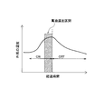
- FIG. 9 is a graph schematically showing the solubility characteristic for explaining the conventional heater control.
- the solubility calculator calculates the solubility X from the pressure Pa in the compressor detected by the shell pressure detector and the temperature T1 detected by the oil temperature detector (step S20).
- step S21 it is determined whether or not the calculated solubility X is higher than the set solubility X 0 (step S21).
- the heater is turned off (step S23), and when the calculated solubility is higher than the set solubility X 0 such as Xb, the heater is turned on (FIG. 9). reference).
- FIG. 9 is modified so as to emphasize a part in order to make it easy to see, in the heater control of Patent Document 3, the heater is turned off while the solubility curve is changed like curves L11, L12, L13, and L14.
- the point Px4 must be searched for.
- the pressure and liquid temperature at the calculated solubility Xb are Pb and T1
- the pressure and temperature measured next change For example, the pressure Pc and the temperature T2.
- the curve L11 cannot be used as the solubility curve, and it must be changed to the curve L12.
- step S20 since the point Px2 on the curve L12 has to be found, it is necessary to return to step S20 and repeat the complicated calculation by the solubility calculator to calculate the solubility Xc.
- the solubility curve must be changed to L11, L12, L13, and L14.
- the solubility Xa, Xb, Xc, Xd, Xe,... Become slow.
- there are various combinations of refrigerants and lubricating oils, and a solubility curve must be prepared for each temperature, which requires design man-hours.
- the refrigeration apparatus of the first embodiment even if the temperature of the lubricating oil 70 and the pressure of the refrigerant change due to the on / off of the crankcase heater 46, the refrigeration apparatus can be obtained from that.
- the oil temperature offset value is obtained from the saturation temperature Tr using the same simple expression representing the curve of FIG. That is, the control device 50 according to the first embodiment does not need to have the solubility curve information, and can simplify the calculation associated with the heater control. Further, even if the types of the lubricating oil and the refrigerant change and it is necessary to obtain data as shown in FIG.
- a predetermined set value for example, oil concentration
- oil temperature offset value for example, 60%
- the saturation temperature and the oil temperature offset value so that it is not necessary to convert the solubility curve into data, and the design man-hour is shortened.
- the on / off control since the parameter for the control device 50 to control the crankcase heater 46 is only the temperature, it is proportional. It is also easy to adopt a configuration that shortens the time until the oil temperature target value Tso is reached using control or the like.
- the straight line LN is close to a curve indicating the relationship between the saturation temperature at which the oil concentration set value is 65% and the oil temperature offset value on the side where the saturation temperature is relatively low, and the oil concentration set value is on the side where the saturation temperature is relatively high. It is set to be close to a curve showing the relationship between the saturation temperature of 60% and the oil temperature offset value.
- the oil concentration control range can be somewhat wide (for example, 60 to 65%), but control within that range is sufficient or other cases. For this reason, it is possible to set so that the set value of the oil concentration changes within a predetermined setting range.
- the straight line LN is used, the oil temperature offset value is obtained by proportional calculation from the saturation temperature, and the control becomes simple.
- the oil concentration is used as a set value, and as shown in FIG. 4, the relationship between the saturation temperature and the oil temperature offset value at which the oil concentration becomes a predetermined set range or a predetermined set value is obtained.
- the control device 50 controls the crankcase heater 46 using the relationship.
- the oil viscosity value may be used for the predetermined setting range or the predetermined setting value when obtaining the relationship between the saturation temperature and the oil temperature offset value.
- the control of the crankcase heater 46 in order to make the oil concentration within a predetermined set range or a predetermined set value has the purpose of preventing the oil viscosity from decreasing, so that the purpose can be achieved directly. Heater control that can be performed may be performed. Even when the oil viscosity is used, the oil temperature offset value can be determined as in the case of the oil concentration.
- the oil temperature detector 62 detects the oil temperature of the lubricating oil 70 in the compressor 40 has been described.
- the oil temperature of the lubricating oil 70 is estimated from the detection results of other measuring devices. You may make it do.
- the detection result of the oil temperature detector 62 may be corrected by using the outside air temperature around the compressor 40, the temperature of the indoor heat exchanger 21, or the like, so as to further improve the accuracy.
- the oil temperature of the lubricating oil 70 in the compressor 40 is estimated from the measurement result of another measuring device that performs the measurement related to the parameter for estimating the oil temperature of the lubricating oil 70. You may do it.
- the control device 50 performs on / off control of the crankcase heater 46.
- the control device 50 may perform control to change the heating amount in accordance with the value of the oil temperature offset value. For example, when the pressure change in the compressor 40 is steep, the value of the oil temperature offset value may become a negative value. In such a case, a change may be made to increase the heating amount as compared with the case where the oil temperature offset value takes a positive value.
- the refrigerant pressure detector 61 is attached to the suction pipe 43 and the pressure of the refrigerant in the compressor 40 is measured on the suction pipe 43 side. However, when the pressure of the refrigerant in the compressor 40 can be measured better on the discharge pipe 42 side than on the suction pipe 43 side, a refrigerant pressure detector 61 is attached to the discharge pipe 42 on the suction pipe 43. The pressure may be detected.
- the saturated gas temperature is used as the saturation temperature, but the saturated liquid temperature may be used as the saturation temperature.
- the crankcase heater 46 is used to warm the lubricating oil 70, but the heater for warming the lubricating oil 70 is not limited to the crankcase heater 46.
- a motor winding heating method by phase loss energization can be used as a method for warming the lubricating oil 70.
- a motor winding is used as a heater for warming the lubricating oil 70.
- the control device 50 performs on / off control of the motor winding heating by phase loss energization as the heater control.
- (6) Outline of refrigeration apparatus In the first embodiment, the control of the heater when the refrigeration apparatus of the air conditioner 10 is turned on and the refrigeration apparatus of the air conditioner 10 continues operating is described. ing. However, in the situation where the refrigeration apparatus of the air conditioner 10 is placed, there is a state where the power of the air conditioner 10 is turned off.
- the air conditioner 10 is capable of performing control for preventing problems due to a decrease in viscosity due to a large amount of refrigerant dissolved in refrigeration oil when the power is turned on after the power is turned off. It is configured.
- the refrigeration apparatus according to the second embodiment can have the same configuration as that of the refrigeration apparatus of the air-conditioning apparatus 10 of the first embodiment. Therefore, in the description of the refrigeration apparatus of the second embodiment below, the refrigeration apparatus of the second embodiment is assumed to have the same configuration as the refrigeration apparatus of the air conditioner 10 of the first embodiment, and the power is turned off. The focus is on re-power-on control.
- Heater Control FIG. 10 is a flowchart showing the heater control operation at the start-up in the refrigeration apparatus of the second embodiment.
- the constant oil concentration control in step S31 is the control described in the first embodiment and indicates heater control other than at the time of startup.
- Steps S32 to S37 are the heater control subroutine of the first embodiment. Accordingly, steps S32 to S37 may be performed at an appropriate time in the heater control of the first embodiment.
- step S32 it is determined whether or not the breaker is turned on for the first time. This is a determination as to whether or not the start is such that a test run is performed. If the breaker is turned on for the first time, it is generally considered that a test run is necessary. Therefore, if the breaker is turned on for the first time, the process proceeds to step S33. In step S33, it is determined whether or not the trial run execution flag is on. If the test operation is being performed, the test operation execution flag is turned on. This trial run execution flag is stored in the memory 50b of the control device 50, for example. If the trial run execution flag is off, the trial run has not been carried out, so the trial run is carried out (step S34).
- the stagnation start here refers to the start that is performed by changing the setting to a more suitable setting for the state in which more refrigerant is dissolved in the lubricating oil in the compressor (sleep state) than the setting that the normal start has. is there.
- a sleep activation is performed (step S35).
- an operation such as a cooling operation or a heating operation is performed (step S39).
- the control device 50 stops the operation of the air conditioner 10 (step S40).
- heater control other than the start-up is performed (step S31).
- step S32 when it is determined that the breaker is not turned on for the first time at the time of activation (step S32), it is determined whether (To-Tr) is equal to or smaller than the target offset value.
- This target offset value is a value obtained by subtracting the saturation temperature Tr from the oil temperature target value Tso at which the target oil concentration is realized, and is calculated and updated as needed in accordance with the change of the situation (at a predetermined time interval). Value. If (To-Tr) is larger than the target offset value, the target oil concentration has been achieved, and normal activation is performed (step S38).
- step S36 If it is determined in step S36 that (To ⁇ Tr) is equal to or smaller than the target offset value, the control device 50 performs sleep activation by level set according to the value of ⁇ T (step S37).
- ⁇ T is ⁇ target offset value ⁇ (To ⁇ Tr) ⁇ .
- this ⁇ T is in the range of 0 ⁇ ⁇ T ⁇ 5 ° C.
- the low-level sleep activation is performed, and if ⁇ T> 5 ° C., the high-level sleep activation is performed.
- the high-level stagnation start-up is more suitable for the start-up when more refrigerant than a predetermined amount is dissolved in the lubricating oil in the compressor than the low-level stagnation start-up.
- step S36 The determination performed in step S36 will be described as follows with a specific example.
- the refrigerant pressure and the oil temperature are read from the intersection of the graph at the target oil concentration, and the oil temperature offset value is obtained.
- the intersections Ps1, Ps2, Ps3, and Ps4 between the oil concentration 60% (solubility 40 wt%) line and the isothermal temperature lines in FIG. 5 are read.
- the pressure at the intersection is converted into the saturation temperature Tr and subtracted from the oil temperature To, (To-Tr) is obtained.
- the control device 50 of the air conditioning apparatus 10 is based on (To ⁇ Tr) and the target offset value (an example of the oil temperature of the lubricating oil and the oil temperature target value) at the time of startup.
- the normal activation and the sleep activation are selected (step S36). Since normal activation and sleep activation can be selected, the sleep activation can be performed by proceeding to step S37 when the sleep activation is necessary, and the reliability can be improved.
- the control device 50 activates the high level sleep activation and the low level sleep activation (a plurality of sleep activations) based on ⁇ T (an example of the oil temperature and the oil temperature target value). Is selected) (step S37). Since an appropriate sleep activation can be selected in this way, the compressor 40 can be activated by selecting a more appropriate sleep activation compared to a case where the sleep activation cannot be selected, and the reliability is further improved.
- the control device 50 selects whether to perform a test run or a sleep start according to the history of the test run implementation at the first startup after the power supplied from the outside to the air conditioner 10 is turned on ( Step S33). Since the test operation and the sleep operation can be switched by the control device 50, it is possible to perform the test operation of the refrigeration apparatus as needed at the site. Thereby, unnecessary sleep activation can be avoided by performing a trial run, and the installation of the refrigeration apparatus becomes easy.
- Modification (8-1) In the second embodiment, even when it is determined in step S33 that the trial operation has been completed, since the state after the stop is unknown, the sleep activation is performed without performing the normal activation. However, the high-level sleep activation set in step S37 may also be applied during the sleep activation.
- a measure for increasing the target oil concentration may be taken.
Landscapes
- Engineering & Computer Science (AREA)
- Physics & Mathematics (AREA)
- Mechanical Engineering (AREA)
- Thermal Sciences (AREA)
- General Engineering & Computer Science (AREA)
- Air Conditioning Control Device (AREA)
- Compressor (AREA)
- Lubricants (AREA)
Abstract
Description
この種の冷凍装置では、圧縮機停止中のクランクケース内の圧力が一定の条件下において潤滑油の温度(以下、油温という)が低いと、クランクケース内の潤滑油に冷媒の溶け込む割合が大きくなる。圧縮機の長期間の運転休止や冷媒の温度(外気の温度)変化などの条件が重なると、いわゆる寝込みと呼ばれる現象が生じて圧縮機内の潤滑油中に多くの冷媒が溶け込む。潤滑油中に冷媒が寝込むと、例えば潤滑油の粘度が低下して潤滑油の性能が低下する。 2. Description of the Related Art Conventionally, as an air conditioner that transfers heat between indoors and outdoors, there is an air conditioner that includes a use side heat exchanger disposed indoors and a heat source side heat exchanger disposed outdoors. In this air conditioner, in order to transfer heat, one of the use side heat exchanger and the heat source side heat exchanger becomes a radiator, and the other becomes an evaporator. For example, in such an air conditioner, since the refrigerant is circulated between the use side heat exchanger and the heat source side heat exchanger to transfer heat, the compressor, the use side heat exchanger, and the heat source that compress the refrigerant are used. Generally, a refrigeration apparatus is configured using a side heat exchanger (a radiator and an evaporator).
In this type of refrigeration system, if the temperature of the lubricating oil (hereinafter referred to as the oil temperature) is low under a constant pressure in the crankcase when the compressor is stopped, the ratio of the refrigerant dissolved in the lubricating oil in the crankcase growing. When conditions such as long-term shutdown of the compressor and changes in the refrigerant temperature (outside air temperature) overlap, a phenomenon called so-called stagnation occurs, and a large amount of refrigerant dissolves in the lubricating oil in the compressor. When the refrigerant stagnates in the lubricating oil, for example, the viscosity of the lubricating oil decreases and the performance of the lubricating oil decreases.
しかし、圧縮機を温めるためにヒータに通電すると一定の電力(待機電力)を消費してしまい、冷凍装置で消費される電力量が増加するという問題を生じる。 Therefore, conventionally, in order to prevent the stagnation of the refrigerant in the compressor, even when a heater is attached to the crankcase and the compressor is stopped, measures are taken to warm the compressor so that the refrigerant does not stagnate. ing. Moreover, the lubricating oil in a compressor may be warmed by the motor winding heating method by phase loss energization.
However, when the heater is energized to warm the compressor, a certain amount of electric power (standby power) is consumed, resulting in an increase in the amount of power consumed by the refrigeration apparatus.
特許文献1や特許文献2の技術では、待機電力が削減できるものの未だ待機電力を削減することができる部分を残しており、また、圧縮機内の潤滑油に溶け込んでいる冷媒の量に基づいて制御するものではないためにヒータによる加熱が不足する場合もある。
一方、特許文献3(特開平9-170826号公報)に記載されている従来の技術では、潤滑油と冷媒との混合液の油濃度(混合液に占める潤滑油の割合)に基づいて圧縮機のヒータの制御を行っている。しかし、特許文献3に記載されているヒータの制御では、冷媒と潤滑油の溶解特性を示す曲線から現在の油濃度を求める計算が複雑になり、実用的ではない。例えば、特許文献3の技術では、冷媒や潤滑油の種類や組合せや条件が変わるたびに溶解度特性を示す曲線を求めなければならないことから、溶解度曲線の元となるデータ取得に掛かるコストやデータを元に作成する回帰式に掛かる作業量が増大するのみならず、動作時のマイクロコンピュータに処理させるデータ量が増加するなど計算負荷が増大する。 In order to reduce the standby power of such a compressor, for example, in Patent Document 1 (Japanese Patent Laid-Open No. 2001-73952) and Patent Document 2 (Japanese Patent No. 4111246), compression is performed based on the refrigerant temperature and the outside air temperature. A technique is described in which a heater is not required to be heated and the standby power is reduced by controlling the heater.
In the techniques of
On the other hand, in the conventional technique described in Patent Document 3 (Japanese Patent Laid-Open No. 9-170826), the compressor is based on the oil concentration (ratio of the lubricating oil in the mixed liquid) of the mixed liquid of the lubricating oil and the refrigerant. The heater is controlled. However, the control of the heater described in
第1観点の冷凍装置によれば、潤滑油の油温目標値と現在の油温とを用いてヒータを制御すると、温度をパラメータとして簡単に制御できる。そして、冷媒の飽和温度に対して所定温度を加えるため、外気などが冷媒の飽和温度に達しないときに冷媒の潤滑油への溶け込みを抑えることができ、油濃度や油粘度を維持し易い。また、冷媒の飽和温度に基づいてヒータのオンオフができるため、外気条件などに左右されずに加熱が不要なところでヒータをオフでき、待機電力も削減できる。 A refrigeration apparatus according to a first aspect of the present invention includes a radiator that dissipates heat from a refrigerant, an evaporator that evaporates the refrigerant, a compressor that compresses the refrigerant circulating between the radiator and the evaporator, and lubrication within the compressor. A heater that heats the oil, and a control device that controls the heater. The control device adds the predetermined temperature to the saturation temperature of the refrigerant in the compressor to an oil temperature target value obtained by adding a predetermined temperature to the oil temperature of the lubricating oil in the compressor. The heater is controlled so that the temperature reaches.
According to the refrigeration apparatus of the first aspect, when the heater is controlled using the target oil temperature value of the lubricating oil and the current oil temperature, the temperature can be easily controlled as a parameter. And since predetermined temperature is added with respect to the saturation temperature of a refrigerant | coolant, when external air etc. do not reach the saturation temperature of a refrigerant | coolant, the melt | dissolution to the lubricating oil of a refrigerant | coolant can be suppressed, and it is easy to maintain oil concentration and oil viscosity. In addition, since the heater can be turned on and off based on the saturation temperature of the refrigerant, the heater can be turned off where heating is not required regardless of outside air conditions and the standby power can be reduced.
第2観点の冷凍装置によれば、所定温度によって、冷媒の圧力において油濃度又は油粘度が所定の設定範囲に入る混合液の温度に油温目標値を設定することにより、ヒータによる加熱が不足しないようにしながら待機電力を削減することができるヒータの制御が行われる。 The refrigeration apparatus according to a second aspect of the present invention is the refrigeration apparatus according to the first aspect, further comprising a refrigerant pressure detector that detects the pressure of the refrigerant in the compressor, and the oil temperature target value is determined according to a predetermined temperature by the refrigerant pressure. The oil concentration or oil viscosity at the time of dissolution equilibrium in is set to the temperature of the mixture of lubricating oil and refrigerant that falls within a predetermined setting range.
According to the refrigeration apparatus of the second aspect, heating by the heater is insufficient by setting the oil temperature target value to the temperature of the mixed liquid in which the oil concentration or the oil viscosity falls within the predetermined setting range at the refrigerant pressure at the predetermined temperature. The heater is controlled so that the standby power can be reduced while avoiding this.
第3観点の冷凍装置によれば、一定の油濃度又は油粘度を維持させる油温になるようにヒータの制御を行わせることができる。 The refrigeration apparatus according to a third aspect of the present invention is the refrigeration apparatus according to the second aspect, wherein the oil temperature target value is a predetermined set value depending on a predetermined temperature, and the oil concentration or oil viscosity at the time of dissolution equilibrium at the refrigerant pressure. The temperature of the mixed liquid of the lubricating oil and the refrigerant is set.
According to the refrigeration apparatus of the third aspect, the heater can be controlled so that the oil temperature maintains a constant oil concentration or oil viscosity.
第4観点の冷凍装置によれば、データを用いて、制御装置における計算などの工数を省くことができる。 In the refrigeration apparatus according to the fourth aspect of the present invention, in any of the refrigeration apparatuses according to the first to third aspects, the control device holds a predetermined temperature as data for each saturation temperature.
According to the refrigeration apparatus of the fourth aspect, man-hours such as calculation in the control apparatus can be omitted using the data.
第5観点の冷凍装置によれば、圧縮機内の潤滑油の油温を測定する専用の温度検出器又は測定器を設けることにより、圧縮機内の潤滑油の油温を比較的正確に検知することができる。 The refrigeration apparatus according to the fifth aspect of the present invention is a temperature detector that measures the temperature of the lubricating oil in the compressor and outputs it to the control device, or a measurement related to a parameter for estimating the temperature of the lubricating oil in the compressor. And a measuring device for performing and outputting to the control device.
According to the refrigeration apparatus of the fifth aspect, the temperature of the lubricating oil in the compressor can be detected relatively accurately by providing a dedicated temperature detector or measuring device for measuring the temperature of the lubricating oil in the compressor. Can do.
第6観点の冷凍装置によれば、通常起動と寝込み起動を的確に選択できるため、圧縮機の信頼性を向上することができる。 A refrigeration apparatus according to a sixth aspect of the present invention is the refrigeration apparatus according to the fifth aspect, wherein the control device performs normal activation and sleep activation based on the oil temperature of the lubricating oil and the oil temperature target value when the refrigeration apparatus is activated. To choose.
According to the refrigeration apparatus of the sixth aspect, normal activation and sleep activation can be accurately selected, so that the reliability of the compressor can be improved.
第7観点の冷凍装置によれば、油温及び油温目標値に基づいて、より適切な寝込み起動を選択でき、寝込み起動が選択できない場合に比べて信頼性が向上する。 In the refrigeration apparatus according to the seventh aspect of the present invention, in the refrigeration apparatus according to the sixth aspect, the sleep activation includes a plurality of sleep activations having different settings, and the control device selects the sleep activation instead of the normal activation. In addition, based on the oil temperature of the lubricating oil and the oil temperature target value, one of a plurality of sleep activations is selected.
According to the refrigeration apparatus of the seventh aspect, more appropriate stagnation activation can be selected based on the oil temperature and the oil temperature target value, and the reliability is improved as compared with the case where stagnation activation cannot be selected.
第8観点の冷凍装置によれば、制御装置により試運転と寝込み運転を切り換えられるので、現場などで必要に応じて冷凍装置の試運転を行なわせることができる。 In the refrigeration apparatus according to the eighth aspect of the present invention, in the refrigeration apparatus according to the sixth aspect or the seventh aspect, the control device is the first start after the power supplied from the outside to the refrigeration apparatus is turned on. It is selected whether to perform a trial run or to perform sleep activation according to the history of trial run implementation.
According to the refrigeration apparatus of the eighth aspect, the trial operation and the sleep operation can be switched by the control device, so that the refrigeration apparatus can be trial-operated as necessary at the site.
本発明の第2観点に係る冷凍装置では、油濃度や油粘度を必要以上に高くなるような制御を行わなくて済むため、待機電力の削減効果が向上する。
本発明の第3観点に係る冷凍装置では、一定の油濃度又は油粘度を維持させながら待機電力を削減することができる。
本発明の第4観点に係る冷凍装置では、制御装置におけるヒータの制御を高速に行なわせることができ、圧縮機の状況変化への応答が速くなる。(本制御で用いる計算領域増大を抑止)
本発明の第5観点に係る冷凍装置では、正確な潤滑油の温度に基づいて正確な制御を行なうことができる。 In the refrigeration apparatus according to the first aspect of the present invention, since the control is simplified by controlling using the saturation temperature and the predetermined temperature, the cost can be reduced, and an appropriate oil for the lubricating oil in the compressor is used. Concentration or oil viscosity can be easily maintained and standby power can be reduced.
In the refrigeration apparatus according to the second aspect of the present invention, it is not necessary to perform control to increase the oil concentration and oil viscosity more than necessary, so that the standby power reduction effect is improved.
In the refrigeration apparatus according to the third aspect of the present invention, standby power can be reduced while maintaining a constant oil concentration or oil viscosity.
In the refrigeration apparatus according to the fourth aspect of the present invention, the control of the heater in the control apparatus can be performed at high speed, and the response to changes in the compressor status is accelerated. (Inhibits the increase in the calculation area used in this control)
In the refrigeration apparatus according to the fifth aspect of the present invention, accurate control can be performed based on the accurate temperature of the lubricating oil.
本発明の第7観点に係る冷凍装置では、適切な寝込み起動の選択により信頼性を向上させることができる。
本発明の第8観点に係る冷凍装置では、試験運転と寝込み運転の切り換えができ、冷凍装置の設置が容易になる。また、不要な寝込み運転を回避できる。 In the refrigeration apparatus according to the sixth aspect of the present invention, the sleep activation can be performed accurately when the sleep activation is necessary, and the reliability is improved.
In the refrigeration apparatus according to the seventh aspect of the present invention, the reliability can be improved by selecting an appropriate sleep activation.
In the refrigeration apparatus according to the eighth aspect of the present invention, the test operation and the sleep operation can be switched, and the installation of the refrigeration apparatus becomes easy. Further, unnecessary sleep operation can be avoided.
<第1実施形態>
(1)冷凍装置の構成
(1-1)冷媒回路
図1は、本発明の第1実施形態に係る冷凍装置が採用された空気調和装置10の構成を示す冷媒回路図である。空気調和装置10は、室内に設置される利用側ユニット20と室外に設置される熱源側ユニット30とを備える。利用側ユニット20には、室内熱交換器21と室内ファン22とが配置されている。熱源側ユニット30には、室外熱交換器31と室外ファン32と電動弁33とアキュムレータ34と四路切換弁35と圧縮機40とが配置されている。 Hereinafter, embodiments of the present invention will be described with reference to the drawings. In addition, embodiment of the compressor based on this invention is not restricted to embodiment described below, It can change in the range which does not deviate from the summary of invention.
<First Embodiment>
(1) Configuration of Refrigeration Device (1-1) Refrigerant Circuit FIG. 1 is a refrigerant circuit diagram showing the configuration of an
この四路切換弁35は、第1ポートから第4ポートまでの4つのポートを有している。四路切換弁35は、冷房時には第1ポートと第2ポートが接続されるとともに第3ポートと第4ポートが接続され、暖房時には第1ポートと第3ポートが接続されるとともに第2ポートと第4ポートが接続される。四路切換弁35の第1ポートには圧縮機40の吐出管42が接続され、第2ポートには室外熱交換器31の一端が接続され、第3ポートには室内熱交換器21の一端が接続され、第4ポートにはアキュムレータ34の吸入管が接続されている。 The
The four-
(1-2)圧縮機の構成
図2は、圧縮機40の部分破断斜視図である。圧縮機40には、円筒状のケーシング41の側部に吐出管42が取り付けられており、上部に吸入管43が取り付けられている。吸入管43の下方には、スクロール44が設けられており、スクロール44を駆動するモータ45がスクロール44の下方に設けられている。潤滑油70は、円筒状のケーシング41の底部41aに溜まるように構成されており、ケーシング41の底部41aに巻付けられるようにクランクケースヒータ46が取り付けられている。また、潤滑油70が溜まる底部41aには、油温検出器62が取り付けられている。 Connection of each part of the
(1-2) Configuration of Compressor FIG. 2 is a partially broken perspective view of the
空気調和装置10は、また、図1に示されているように、空気調和装置10の動作の制御のための制御装置50及び各種の計測機器を備えている。ここでは、計測機器について、圧縮機40のクランクケースヒータ46の制御に関連するものを示し、他の多くの計測機器については記載を省略している。制御装置50は、例えばCPU(中央演算処理装置)50a及びメモリ50bなどを備えるマイクロコンピュータで構成される。
制御装置50は、室内ファン22のファンモータ22a、室外ファン32のファンモータ32a、電動弁33、四路切換弁35、及び圧縮機40のモータ45及びクランクケースヒータ46に接続されている。また、制御装置50には、圧縮機40の吸入管43の圧力を測定する冷媒圧力検出器61、圧縮機40内の潤滑油70の温度を検出する油温検出器62、外気温を検出する外気温検出器63及び室内熱交換器21の温度を検出する熱交温度検出器64が接続されている。 (1-3) Control Device and Measuring Equipment As shown in FIG. 1, the
The
制御装置50によるクランクケースヒータ46の制御について図3のフローチャートに沿って説明する。この制御装置50は、圧縮機40のモータ45を制御しているので、圧縮機40の動作と停止の状態に関する情報を有している。
制御装置50は、圧縮機40が停止している状態において、まず、冷媒圧力検出器61の検出結果を受けて、圧縮機40内の飽和温度を算出する(ステップS10)。冷媒の飽和温度Trは、冷媒の圧力LPが分かれば、従来からよく知られた方法を用いて、冷媒の圧力と飽和温度との関係から簡単に算出される。例えば、制御装置50は、冷媒の圧力LPと飽和ガス温度(以下、飽和温度Trという)の関係を示す関係式faを記憶しており、その関係式faを用いて飽和温度Trを算出する。 (2) Control of Crank Heater Control of the
In a state where the
図4は、飽和温度Trと油温オフセット値との関係を示すグラフである。図4に示されているグラフは、油濃度Csoによって異なったものになる。図4には、油濃度Csoが60%(冷媒濃度が40%)の場合と油濃度Csoが70%(冷媒濃度が30%)の場合の2つのグラフが示されている。例えば、その空気調和装置10の冷凍装置の油濃度Csoが60%に決められている場合、図4の下側の60%のデータを用い、それ以外のデータは用いない。ステップS10で求まった飽和温度Trが5℃であれば、点P1から油温オフセット値がTos1℃に決まる。従って、油温目標値Tsoは、5℃+Tos1℃(飽和温度Tr+油温オフセット値)に決まる。図4に示されているグラフは、例えば簡単な2次式fbで近似されており、制御装置50は、油濃度Csoと飽和温度Trの値から油温目標値Tsoを計算する。式fb(Tr)は、油濃度Cso毎にその式が用意されている。そして、油濃度Csoの値によって式を選択して、選択された式fb(Tr)を使って飽和温度Trの値から油温目標値Tsoが算出される。 Next, the
FIG. 4 is a graph showing the relationship between the saturation temperature Tr and the oil temperature offset value. The graph shown in FIG. 4 varies depending on the oil concentration Cso . FIG. 4 shows two graphs when the oil concentration C so is 60% (refrigerant concentration is 40%) and when the oil concentration C so is 70% (refrigerant concentration is 30%). For example, when the oil concentration Cso of the refrigeration apparatus of the
ステップS13において、制御装置50は、油温目標値Tsoと油温Toとを比較して、油温Toが油温目標値Tsoに達していなければステップS14に進み、クランクケースヒータ46をオンにしてステップS10に戻る。もし、ステップS13で、油温目標値Tsoと油温Toとを比較して、油温Toが油温目標値Tsoに達していれば、制御装置50は、ステップS15に進み、クランクケースヒータ46をオフにしてステップS10に戻る。 The
In step S13, the
(3)油温オフセット値
このように空気調和装置10の冷凍装置は、制御装置50の制御によって、圧縮機40の停止中に潤滑油70の油温Toが油温目標値Tsoに達する状態を維持できるように構成されている。そして、油温目標値Tsoは、飽和温度Tr+油温オフセット値によって定まる。
この油温オフセット値は、油温目標値Tsoが冷媒の圧力LPにおける溶解平衡時の油濃度が所定の設定値になる潤滑油70と冷媒の混合液の温度に設定されている。
(3) oil temperature offset value thus refrigerating device of an
The oil temperature offset value is set to the temperature of the mixed liquid of the lubricating
図5のグラフにおいて、点Ps1は、溶解平衡時に圧力がα1、液温がβ1の状態で油濃度が60%(冷媒の溶解度が40%)になる点である。そして、図6に示されているように、点Ps1の状態ST1でクランクケースヒータ46をオンせずに放置すると、液温は、現在の液温β1から圧力α1で平衡状態ST2を保つ冷媒の飽和温度Trα1に変化する。このとき、冷媒はさらに潤滑油中に溶解して、油濃度は60%から低下する。つまり、油濃度を60%に保つには、液温をβ1に保てばよい。 This point will be described with reference to FIG. FIG. 5 is a graph showing the relationship between the refrigerant pressure LP, the temperature of the mixed liquid of the lubricating
In the graph of FIG. 5, the point Ps1 is a point where the oil concentration is 60% (the solubility of the refrigerant is 40%) when the pressure is α1 and the liquid temperature is β1 at the time of dissolution equilibrium. Then, as shown in FIG. 6, when the
冷媒の飽和温度毎の油温オフセット値の決定の仕方を図4及び図5を用いて説明する。油濃度については、その所望の設定値が信頼性と待機電力削減の観点から冷凍装置毎に決定される。従って、油濃度が例えば60%に設定される冷凍装置であれば、溶解度が40%になる縦軸に平行な直線(以下40%ラインという)と各曲線L1,L2,L3,L4…との関係を見ればよい。そうすると、40%ラインが圧力α2の点Ps2で交わる溶解度曲線はL2であり、40%ラインが圧力α3の点Ps3で交わる曲線はL3であり、40%ラインが圧力α4の点Ps4で交わる曲線はL4である。一方、圧力α2で油温と飽和温度が等しくなる点Pth2を通る二点鎖線で示されている仮想の溶解度曲線の温度はTrα2になる。同様に、圧力α3の点Pth3を通る仮想の溶解度曲線の温度はTrα3になり、圧力α4の点Pth4を通る仮想の溶解度曲線の温度はTrα4になる。従って、圧力α2のときの油温オフセット値は、曲線L2の示す温度β2から温度Trα2を引いた値になる。同様に、油温オフセット値は、圧力α3のときは曲線L3の示す温度β3から温度Trα3を引いた値になり、圧力α4のときは曲線L4の示す温度β4から温度Trα4を引いた値になる。 Accordingly, the oil temperature offset value (oil concentration in pressure upon dissolution equilibrium [alpha] 1 is the liquid temperature to 60%) - is given by (saturation temperature of the refrigerant pressure [alpha] 1), i.e. β1-T r α 1.
A method for determining the oil temperature offset value for each saturation temperature of the refrigerant will be described with reference to FIGS. About oil concentration, the desired setting value is determined for every refrigeration apparatus from a viewpoint of reliability and standby power reduction. Therefore, in the case of a refrigeration apparatus in which the oil concentration is set to 60%, for example, a straight line parallel to the vertical axis (hereinafter referred to as the 40% line) at which the solubility is 40% and the curves L1, L2, L3, L4. Look at the relationship. Then, the solubility curve where the 40% line intersects at the point Ps2 of the pressure α2 is L2, the curve where the 40% line intersects at the point Ps3 of the pressure α3 is L3, and the curve where the 40% line intersects at the point Ps4 of the pressure α4 is L4. On the other hand, the temperature of the solubility curve of the virtual indicated by the two-dot chain line passing through the point P th2 saturation temperature and the oil temperature is equal in pressure α2 becomes T r alpha 2. Similarly, the temperature of the solubility curve of the virtual through the points P th3 pressure α3 becomes T r alpha 3, the temperature of the solubility curve of the virtual through the points P th4 pressure α4 becomes T r alpha 4. Accordingly, the oil temperature offset value when the pressure α2 is a value obtained by subtracting the temperature T r alpha 2 from the temperature β2 indicated by curve L2. Similarly, the oil temperature offset value is a value obtained by subtracting the temperature T r α 3 from the
このようにして図5のグラフから求められる4つの飽和温度の油温オフセット値をプロットしたものが図4に示されているグラフの点P1,P2,P3,P4である。例えば、求められた各点P1,P2,P3,P4…について最小二乗法などを適用して、各点の間を補完することで飽和温度と油温オフセット値との関係を示すグラフが完成する。図4に示されているグラフの曲線を示す近似式が、データとして制御装置50のメモリ50bに記憶されている。
(4)特徴
(4-1)
以上説明したように、空気調和装置10の冷凍装置は、室内熱交換器21(放熱器又は蒸発器)と室外熱交換器31(蒸発器又は放熱器)と圧縮機40とクランクケースヒータ46と制御装置50と冷媒圧力検出器61と油温検出器62を備えて構成されている。そして、制御装置50は、圧縮機40内の冷媒の飽和温度Trに対して油温オフセット値(所定温度)を加えて得られる油温目標値Tsoに圧縮機40内の潤滑油の油温Toが達するようにヒータを制御する。 As described above, the oil temperature offset value is a value determined as one when the pressure of the refrigerant in the
Plots of the oil temperature offset values of the four saturation temperatures obtained from the graph of FIG. 5 in this way are points P1, P2, P3, and P4 of the graph shown in FIG. For example, a graph showing the relationship between the saturation temperature and the oil temperature offset value is completed by applying a least square method or the like to the obtained points P1, P2, P3, P4. . An approximate expression showing the curve of the graph shown in FIG. 4 is stored in the
(4) Features (4-1)
As described above, the refrigeration apparatus of the
一方、上記第1実施形態の制御装置50では、油温目標値Tsoは、油温オフセット値(所定温度)によって、圧縮機40内の冷媒の圧力における溶解平衡時の油濃度が所定の設定値(例えば60%)になる潤滑油70と冷媒の混合液の温度(例えばβ1~β4など)に設定されている。そのため、外気の温度によってヒータ制御が左右されずに制御装置50が油濃度でクランクケースヒータ46の制御を行うことができ、高油濃度区間でクランクケースヒータ46をオンすることがなく、待機電力の削減を行うことができる。そして、制御装置50は、一定の油濃度を維持させる油温になるようにクランクケースヒータ46の制御を行うことができる。 For example, in the techniques shown in
On the other hand, in the
また、制御装置50のメモリ50bが記憶するデータも少なく、図4に示されている飽和温度毎に油温オフセット値(所定温度)をデータとして保持していれば、制御装置50における計算などに必要な記憶容量や計算負荷を省くことができる。それにより、制御装置50におけるクランクケースヒータ46の制御を高速に行なわせることができ、圧縮機40の状況変化への応答が速くなる。
(5)変形例
(5-1)
制御装置50が保持する飽和温度と油温オフセット値の関係は、油濃度が60%になる曲線を示すものではなく、所定の設定範囲、例えば60~65%の間に入る曲線や直線で示されていてもよい。例えば、図4の直線LNは、油濃度の設定範囲60~65%の間に入る直線である。直線LNは、飽和温度が比較的低い側では、油濃度設定値が65%の飽和温度と油温オフセット値の関係を示す曲線に近く、飽和温度が比較的高い側では、油濃度設定値が60%の飽和温度と油温オフセット値の関係を示す曲線に近くなるように設定されている。 (4-2)
Further, there is little data stored in the
(5) Modification (5-1)
The relationship between the saturation temperature held by the
(5-2)
上記第1実施形態では、油濃度を設定値として用いて、図4に示されているように、油濃度が所定の設定範囲あるいは所定の設定値になる飽和温度と油温オフセット値の関係を求め、その関係を用いて制御装置50がクランクケースヒータ46を制御している。
しかし、飽和温度と油温オフセット値の関係を求める際の所定の設定範囲あるいは所定の設定値に用いるのは、油濃度の値ではなく、油粘度の値を用いてもよい。元々、油濃度を所定の設定範囲あるいは所定の設定値にすべく、クランクケースヒータ46の制御を行うのは、油粘度が低下することを防ぐ目的があるので、直接その目的を達成することができるようなヒータ制御を行ってもよい。油粘度を用いる場合でも油濃度の場合と同様に油温オフセット値を定めることができる。 When the
(5-2)
In the first embodiment, the oil concentration is used as a set value, and as shown in FIG. 4, the relationship between the saturation temperature and the oil temperature offset value at which the oil concentration becomes a predetermined set range or a predetermined set value is obtained. The
However, instead of the oil concentration value, the oil viscosity value may be used for the predetermined setting range or the predetermined setting value when obtaining the relationship between the saturation temperature and the oil temperature offset value. Originally, the control of the
上記第1実施形態では、油温検出器62によって、圧縮機40内の潤滑油70の油温を検出する場合について説明したが、他の測定装置の検出結果から潤滑油70の油温を推定するようにしてもよい。例えば、油温検出器62の検出結果に対して、圧縮機40の周辺の外気温や室内熱交換器21の温度などを用いて補正を加えてさらに精度を高めるような推定を行ってもよい。あるいは、油温検出器62を用いないで、潤滑油70の油温を推定するためのパラメータに関する測定を行う他の計測器の計測結果から圧縮機40内の潤滑油70の油温を推定するようにしてもよい。
(5-4)
上記第1実施形態では、制御装置50は、クランクケースヒータ46のオンオフ制御を行っているが、油温オフセット値の値に応じて加熱量を変化させるような制御を行ってもよい。例えば、圧縮機40内の圧力変化が急峻な場合に油温オフセット値の値が負の値になることがある。そのような場合には、油温オフセット値が正の値をとる場合よりも加熱量を増加させるような変更を行ってもよい。 (5-3)
In the first embodiment, the case where the
(5-4)
In the first embodiment, the
上記第1実施形態では、冷媒圧力検出器61を吸入管43に取り付けて、吸入管43の側で圧縮機40内の冷媒の圧力を測定している。しかし、圧縮機40内の冷媒の圧力を吸入管43の側よりも吐出管42の側の方がよりよく測定できる場合には、吐出管42に冷媒圧力検出器61を吸入管43に取り付けて圧力を検出してもよい。
(5-6)
上記第1実施形態では、飽和温度として飽和ガス温度を用いたが、飽和温度として飽和液温度を用いてもよい。
(5-7)
上記第1実施形態では、潤滑油70を温めるためにクランクケースヒータ46を用いたが、潤滑油70を温めるためのヒータはクランクケースヒータ46に限られない。例えば潤滑油70を温める方法として欠相通電によるモータ巻き線加熱方法を用いることもでき、この場合には潤滑油70を温めるヒータとしてモータ巻き線が用いられる。この場合、制御装置50は、ヒータの制御として、欠相通電によるモータ巻き線加熱のオンオフ制御を行う。
<第2実施形態>
(6)冷凍装置の概要
上記第1実施形態では、空気調和装置10の冷凍装置の電源が投入され、空気調和装置10の冷凍装置が動作状態を継続しているときのヒータの制御について説明している。しかし、空気調和装置10の冷凍装置が置かれる状況の中には、空気調和装置10の電源が切られた状態というものも存在する。電源が切られた状態で長期間停止している圧縮機40では、圧縮機40内の冷凍機油の加熱ができず、外気温の変化により冷凍機油に冷媒が多量に溶解する場合がある。以下に説明する第2実施形態による空気調和装置10は、電源が切られた後の再電源投入時に、冷凍機油に溶け込んだ多量の冷媒による粘度低下による不具合を防止するための制御ができるように構成されている。 (5-5)
In the first embodiment, the
(5-6)
In the first embodiment, the saturated gas temperature is used as the saturation temperature, but the saturated liquid temperature may be used as the saturation temperature.
(5-7)
In the first embodiment, the
<Second Embodiment>
(6) Outline of refrigeration apparatus In the first embodiment, the control of the heater when the refrigeration apparatus of the
(7)ヒータ制御
図10は、第2実施形態の冷凍装置における起動時のヒータ制御の動作を示すフローチャートである。ステップS31の油濃度一定制御は、第1実施形態で説明した制御であって起動時以外のヒータ制御を示している。言い換えると、ステップS32乃至ステップS37は、第1実施形態のヒータ制御のサブルーチンということになる。従って、ステップS32からステップS37は、第1実施形態のヒータ制御において適当な時点で行なわれればよい。 Thus, the refrigeration apparatus according to the second embodiment can have the same configuration as that of the refrigeration apparatus of the air-
(7) Heater Control FIG. 10 is a flowchart showing the heater control operation at the start-up in the refrigeration apparatus of the second embodiment. The constant oil concentration control in step S31 is the control described in the first embodiment and indicates heater control other than at the time of startup. In other words, Steps S32 to S37 are the heater control subroutine of the first embodiment. Accordingly, steps S32 to S37 may be performed at an appropriate time in the heater control of the first embodiment.
ステップS36で(To-Tr)が目標オフセット値と同じか又はそれよりも小さいと判断されると、制御装置50は、ΔTの値に応じて設定されたレベル別寝込み起動を行う(ステップS37)。ここで、ΔTは、{目標オフセット値-(To-Tr)}である。例えば、このΔTが0≦ΔT≦5℃の範囲であれば、低レベル寝込み起動を行い、ΔT>5℃の範囲であれば高レベル寝込み起動を行う。低レベル寝込み起動よりも高レベル寝込み起動の方が、圧縮機内の潤滑油中に所定量よりも多くの冷媒が溶け込んだ場合の起動に適した設定になっている。 On the other hand, when it is determined that the breaker is not turned on for the first time at the time of activation (step S32), it is determined whether (To-Tr) is equal to or smaller than the target offset value. This target offset value is a value obtained by subtracting the saturation temperature Tr from the oil temperature target value Tso at which the target oil concentration is realized, and is calculated and updated as needed in accordance with the change of the situation (at a predetermined time interval). Value. If (To-Tr) is larger than the target offset value, the target oil concentration has been achieved, and normal activation is performed (step S38).
If it is determined in step S36 that (To−Tr) is equal to or smaller than the target offset value, the
このように、実際の実験などによって得られるグラフから直接読み取るため(冷媒の圧力と油温と目標油濃度との実際の関係から直接導くため)、制御装置50のヒータ制御に用いられる全パラメータの関係が高精度に再現される。
また、圧縮機40の保有するドーム内保有油量(100%)が明確な場合は、目標油濃度から逆算して油面高さが算出できる。そのため、起動時にターミナルが潤滑油に漬かって生じるターミナル絶縁不良が起こる可能性がある場合には、目標油濃度を変更して絶縁不良が起こらないように制御装置50に制御させることもできる。 The determination performed in step S36 will be described as follows with a specific example. First, the refrigerant pressure and the oil temperature are read from the intersection of the graph at the target oil concentration, and the oil temperature offset value is obtained. For example, the intersections Ps1, Ps2, Ps3, and Ps4 between the
As described above, in order to directly read from a graph obtained by an actual experiment or the like (to directly derive from the actual relationship between the refrigerant pressure, the oil temperature, and the target oil concentration), all the parameters used for the heater control of the
In addition, when the amount of oil retained in the dome (100%) possessed by the
(7-1)
以上説明したように、第2実施形態の空気調和装置10の制御装置50は、起動時に、(To-Tr)及び目標オフセット値(潤滑油の油温及び油温目標値の一例)に基づき、通常起動と寝込み起動の選択を行う(ステップS36)。通常起動と寝込み起動を選択できるため、寝込み起動が必要なときにはステップS37に進んで寝込み起動を行うことができ、信頼性を向上することができる。
(7-2)
制御装置50は、通常起動ではなくて寝込み起動を選択する場合に、ΔT(潤滑油の油温及び油温目標値の一例)に基づき、高レベル寝込み起動及び低レベル寝込み起動(複数の寝込み起動の一例)のうちのいずれかを選択する(ステップS37)。このように適切な寝込み起動を選択できることから、寝込み起動が選択できない場合に比べて、より適切な寝込み起動を選択して圧縮機40を起動することができ、信頼性がさらに向上する。 (7) Features (7-1)
As described above, the
(7-2)
When the
制御装置50は、空気調和装置10に外部から供給される電源がオンされた後の最初の起動のときに、試運転実施の履歴に応じて試運転を行うか又は寝込み起動を行うかを選択する(ステップS33)。制御装置50により試運転と寝込み運転を切り換えられるので、現場などで必要に応じて冷凍装置の試運転を行なわせることができる。それにより、試運転を行なうことで不要な寝込み起動を回避でき、冷凍装置の設置が容易になる。
(8)変形例
(8-1)
上記第2実施形態では、ステップS33で試運転が終了していると判断された場合でも、停止後の状態が不明なので、通常起動は行わずに寝込み起動を行っている。しかし、さらに、寝込み起動の中でも、ステップS37で設定されている高レベル寝込み起動を適用してもよい。 (7-3)
The
(8) Modification (8-1)
In the second embodiment, even when it is determined in step S33 that the trial operation has been completed, since the state after the stop is unknown, the sleep activation is performed without performing the normal activation. However, the high-level sleep activation set in step S37 may also be applied during the sleep activation.
21 室内熱交換器
31 室外熱交換器
40 圧縮機
46 クランクケースヒータ
50 制御装置
61 冷媒圧力検出器
62 油温検出器 DESCRIPTION OF
Claims (8)
- 冷媒を放熱させる放熱器(21,31)と、
前記冷媒を蒸発させる蒸発器(31,21)と、
前記放熱器と前記蒸発器の間を循環する前記冷媒を圧縮する圧縮機(40)と、
前記圧縮機内の潤滑油を加熱するヒータ(46)と、
前記ヒータを制御する制御装置(50)と
を備え、
前記制御装置は、前記圧縮機内の前記冷媒の飽和温度に対して所定温度を加えて得られる油温目標値に前記圧縮機内の前記潤滑油の油温が達するように前記ヒータを制御する、冷凍装置。 Radiators (21, 31) for radiating the refrigerant,
Evaporators (31, 21) for evaporating the refrigerant;
A compressor (40) for compressing the refrigerant circulating between the radiator and the evaporator;
A heater (46) for heating the lubricating oil in the compressor;
A control device (50) for controlling the heater,
The control device controls the heater so that the oil temperature of the lubricating oil in the compressor reaches a target oil temperature value obtained by adding a predetermined temperature to the saturation temperature of the refrigerant in the compressor. apparatus. - 前記圧縮機内の前記冷媒の圧力を検出する冷媒圧力検出器(61)をさらに備え、
前記油温目標値は、前記所定温度によって、前記冷媒の圧力における溶解平衡時の油濃度又は油粘度が所定の設定範囲に入る前記潤滑油と前記冷媒の混合液の温度に設定されている、
請求項1に記載の冷凍装置。 A refrigerant pressure detector (61) for detecting the pressure of the refrigerant in the compressor;
The oil temperature target value is set to the temperature of the mixed liquid of the lubricating oil and the refrigerant in which the oil concentration or oil viscosity at the time of dissolution equilibrium at the refrigerant pressure falls within a predetermined setting range according to the predetermined temperature.
The refrigeration apparatus according to claim 1. - 前記油温目標値は、前記所定温度によって、前記冷媒の圧力における溶解平衡時の油濃度又は油粘度が所定の設定値になる前記潤滑油と前記冷媒の混合液の温度に設定されている、
請求項2に記載の冷凍装置。 The oil temperature target value is set to the temperature of the mixed liquid of the lubricating oil and the refrigerant at which the oil concentration or oil viscosity at the time of dissolution equilibrium at the refrigerant pressure becomes a predetermined set value by the predetermined temperature.
The refrigeration apparatus according to claim 2. - 前記制御装置は、前記飽和温度毎に前記所定温度をデータとして保持している、
請求項1から3のいずれか一項に記載の冷凍装置。 The control device holds the predetermined temperature as data for each saturation temperature,
The refrigeration apparatus according to any one of claims 1 to 3. - 前記圧縮機内の前記潤滑油の油温を測定して前記制御装置に出力する温度検出器(62)又は前記圧縮機内の前記潤滑油の油温を推定するためのパラメータに関する測定を行って前記制御装置に出力する測定器(62,63,64)をさらに備える、
請求項1から4のいずれか一項に記載の冷凍装置。 The temperature sensor (62) that measures the temperature of the lubricating oil in the compressor and outputs it to the control device or the parameter for estimating the temperature of the lubricating oil in the compressor is measured and the control is performed. A measuring instrument (62, 63, 64) for outputting to the apparatus;
The refrigeration apparatus according to any one of claims 1 to 4. - 前記制御装置は、前記冷凍装置の起動時に、前記潤滑油の油温及び前記油温目標値に基づき、通常起動と寝込み起動とを選択する、
請求項5に記載の冷凍装置。 The control device selects normal activation and sleep activation based on the oil temperature of the lubricating oil and the oil temperature target value when the refrigeration apparatus is activated.
The refrigeration apparatus according to claim 5. - 前記寝込み起動は、設定が互いに異なる複数の寝込み起動を含み、
前記制御装置は、前記通常起動ではなくて前記寝込み起動を選択する場合に、前記潤滑油の油温及び前記油温目標値に基づき、複数の前記寝込み起動のうちのいずれかを選択する、
請求項6に記載の冷凍装置。 The sleep activation includes a plurality of sleep activations having different settings.
When the controller selects the stagnation activation instead of the normal activation, the controller selects one of the plurality of stagnation activations based on the oil temperature of the lubricant and the oil temperature target value.
The refrigeration apparatus according to claim 6. - 前記制御装置は、前記冷凍装置に外部から供給される電源がオンされた後の最初の起動のときに、試運転実施の履歴に応じて試運転を行うか又は前記寝込み起動を行うかを選択する、
請求項6又は請求項7に記載の冷凍装置。 The control device selects whether to perform a trial run or the sleep activation according to a history of trial run implementation at the first startup after power supplied from the outside to the refrigeration apparatus is turned on,
The refrigeration apparatus according to claim 6 or 7.
Priority Applications (5)
| Application Number | Priority Date | Filing Date | Title |
|---|---|---|---|
| CN201280047134.8A CN103827597B (en) | 2011-09-30 | 2012-09-28 | Refrigerating plant |
| US14/347,807 US9939184B2 (en) | 2011-09-30 | 2012-09-28 | Refrigeration device |
| AU2012317420A AU2012317420B2 (en) | 2011-09-30 | 2012-09-28 | Refrigeration device |
| EP12835998.1A EP2781855B1 (en) | 2011-09-30 | 2012-09-28 | Refrigeration device |
| BR112014007664-2A BR112014007664B1 (en) | 2011-09-30 | 2012-09-28 | COOLING DEVICE |
Applications Claiming Priority (4)
| Application Number | Priority Date | Filing Date | Title |
|---|---|---|---|
| JP2011218390 | 2011-09-30 | ||
| JP2011-218390 | 2011-09-30 | ||
| JP2012-213551 | 2012-09-27 | ||
| JP2012213551A JP5240392B2 (en) | 2011-09-30 | 2012-09-27 | Refrigeration equipment |
Publications (1)
| Publication Number | Publication Date |
|---|---|
| WO2013047754A1 true WO2013047754A1 (en) | 2013-04-04 |
Family
ID=47995779
Family Applications (1)
| Application Number | Title | Priority Date | Filing Date |
|---|---|---|---|
| PCT/JP2012/075095 WO2013047754A1 (en) | 2011-09-30 | 2012-09-28 | Refrigeration device |
Country Status (7)
| Country | Link |
|---|---|
| US (1) | US9939184B2 (en) |
| EP (1) | EP2781855B1 (en) |
| JP (1) | JP5240392B2 (en) |
| CN (1) | CN103827597B (en) |
| AU (1) | AU2012317420B2 (en) |
| BR (1) | BR112014007664B1 (en) |
| WO (1) | WO2013047754A1 (en) |
Cited By (1)
| Publication number | Priority date | Publication date | Assignee | Title |
|---|---|---|---|---|
| EP2952833A3 (en) * | 2014-05-16 | 2016-04-06 | Lennox Industries Inc. | Compressor operation management in air conditioners |
Families Citing this family (22)
| Publication number | Priority date | Publication date | Assignee | Title |
|---|---|---|---|---|
| US9903627B2 (en) * | 2012-11-06 | 2018-02-27 | Carrier Corporation | Method of operating an air conditioning system including reducing the energy consumed by the compressor crank case heaters |
| JP6440930B2 (en) * | 2013-06-20 | 2018-12-19 | 三菱重工サーマルシステムズ株式会社 | Air conditioner and control method of air conditioner |
| JP6236734B2 (en) * | 2013-07-24 | 2017-11-29 | 三浦工業株式会社 | heat pump |
| JP5959500B2 (en) * | 2013-12-27 | 2016-08-02 | 三菱電機株式会社 | Air conditioner and control method of air conditioner |
| CN104749348A (en) * | 2013-12-31 | 2015-07-01 | 丹佛斯(天津)有限公司 | Method for measuring dilutability and viscosity of lubricating oil, control method and module and refrigerating air-conditioning system |
| JP5847366B1 (en) * | 2014-02-18 | 2016-01-20 | 三菱電機株式会社 | Air conditioner |
| JP6397372B2 (en) * | 2015-06-12 | 2018-09-26 | 荏原冷熱システム株式会社 | Compression refrigerator |
| JP2017009212A (en) * | 2015-06-24 | 2017-01-12 | ダイキン工業株式会社 | Air conditioner |
| JP6309169B2 (en) * | 2015-07-08 | 2018-04-11 | 三菱電機株式会社 | Air conditioner |
| CN107036331A (en) * | 2015-07-15 | 2017-08-11 | 艾默生环境优化技术(苏州)有限公司 | Air conditioning system and method for controlling heating of oil sump of compressor of air conditioning system |
| WO2017085886A1 (en) | 2015-11-20 | 2017-05-26 | 三菱電機株式会社 | Refrigeration cycle device and refrigeration cycle device control method |
| JP6600597B2 (en) * | 2016-05-02 | 2019-10-30 | 荏原冷熱システム株式会社 | Turbo refrigerator |
| CN110192070A (en) * | 2017-01-25 | 2019-08-30 | 三菱电机株式会社 | Refrigerating circulatory device |
| US11306952B2 (en) * | 2017-12-06 | 2022-04-19 | Mitsubishi Electric Corporation | Refrigeration cycle apparatus |
| US11073313B2 (en) * | 2018-01-11 | 2021-07-27 | Carrier Corporation | Method of managing compressor start for transport refrigeration system |
| US11624531B2 (en) | 2018-06-22 | 2023-04-11 | Carrier Corporation | Oil control system and method for HVAC system |
| US11435125B2 (en) | 2019-01-11 | 2022-09-06 | Carrier Corporation | Heating compressor at start-up |
| US11624539B2 (en) | 2019-02-06 | 2023-04-11 | Carrier Corporation | Maintaining superheat conditions in a compressor |
| US20210310708A1 (en) * | 2020-04-01 | 2021-10-07 | Philip Brash | Refrigerant Identification Assembly |
| CN112303862B (en) * | 2020-10-09 | 2023-03-28 | 青岛海尔空调电子有限公司 | Oil temperature control system and method for refrigeration oil in air-conditioning compressor |
| CN112325519A (en) * | 2020-11-25 | 2021-02-05 | 珠海格力电器股份有限公司 | Oil storage device and air conditioning unit with same |
| CN115435230B (en) * | 2022-09-02 | 2024-01-16 | 江森自控空调冷冻设备(无锡)有限公司 | Method for controlling viscosity of lubricating oil of centrifugal compressor |
Citations (11)
| Publication number | Priority date | Publication date | Assignee | Title |
|---|---|---|---|---|
| JPH0618076A (en) * | 1992-07-01 | 1994-01-25 | Daikin Ind Ltd | Controller for operation of air conditioner |
| JPH09170826A (en) | 1995-12-21 | 1997-06-30 | Matsushita Electric Ind Co Ltd | Air conditioner |
| JP2000130866A (en) * | 1998-10-26 | 2000-05-12 | Hitachi Ltd | Air conditioner |
| JP2001073952A (en) | 1999-09-03 | 2001-03-21 | Yamaha Motor Co Ltd | Heating device for compressor |
| JP2003042603A (en) * | 2001-08-02 | 2003-02-13 | Mitsubishi Electric Corp | Refrigerating cycle apparatus, method for manufacturing the same and method for operating the same |
| JP2005351590A (en) * | 2004-06-14 | 2005-12-22 | Matsushita Electric Ind Co Ltd | Cooling/warming system |
| JP2006170575A (en) * | 2004-12-17 | 2006-06-29 | Mitsubishi Heavy Ind Ltd | Compressor control system |
| JP2008014577A (en) * | 2006-07-06 | 2008-01-24 | Ebara Corp | Bearing lubricating device for compression type refrigerating machine |
| JP4111246B2 (en) | 2006-08-11 | 2008-07-02 | ダイキン工業株式会社 | Refrigeration equipment |
| JP2009085463A (en) * | 2007-09-28 | 2009-04-23 | Fujitsu General Ltd | Air conditioner |
| JP2011102674A (en) * | 2009-11-11 | 2011-05-26 | Mitsubishi Electric Corp | Air conditioning machine |
Family Cites Families (16)
| Publication number | Priority date | Publication date | Assignee | Title |
|---|---|---|---|---|
| US3705499A (en) | 1971-09-23 | 1972-12-12 | Carrier Corp | Oil dilution control |
| US4624112A (en) * | 1985-08-26 | 1986-11-25 | Murray Corporation | Automotive air conditioner charging station with over-ride controls |
| JP2967574B2 (en) * | 1990-11-16 | 1999-10-25 | 株式会社日立製作所 | Refrigeration equipment |
| US5318151A (en) * | 1993-03-17 | 1994-06-07 | Ingersoll-Rand Company | Method and apparatus for regulating a compressor lubrication system |
| US5577390A (en) * | 1994-11-14 | 1996-11-26 | Carrier Corporation | Compressor for single or multi-stage operation |
| JPH0933123A (en) * | 1995-07-19 | 1997-02-07 | Daikin Ind Ltd | Cryostatic refrigerating device |
| JPH10148405A (en) * | 1996-11-20 | 1998-06-02 | Hitachi Ltd | Refrigerating/air-conditioning equipment |
| US20030077179A1 (en) * | 2001-10-19 | 2003-04-24 | Michael Collins | Compressor protection module and system and method incorporating same |
| JP3685180B2 (en) * | 2003-04-14 | 2005-08-17 | ダイキン工業株式会社 | Hermetic compressor |
| KR101108311B1 (en) * | 2003-10-09 | 2012-01-25 | 파나소닉 주식회사 | Heating system and automatic vending machine |
| US7410446B2 (en) * | 2005-12-19 | 2008-08-12 | Caterpillar Inc. | Oil warming strategy for transmission |
| US7409871B2 (en) * | 2006-03-16 | 2008-08-12 | Celerity, Inc. | Mass flow meter or controller with inclination sensor |
| US7536276B2 (en) * | 2006-07-27 | 2009-05-19 | Siemens Buildings Technologies, Inc. | Method and apparatus for equipment health monitoring |
| WO2008018381A1 (en) | 2006-08-11 | 2008-02-14 | Daikin Industries, Ltd. | Refrigeration device |
| EP2321595B1 (en) * | 2008-07-23 | 2017-10-04 | Carrier Corporation | Methods and systems for compressor operation |
| JP5326900B2 (en) * | 2009-07-21 | 2013-10-30 | 株式会社Ihi | Turbo compressor and refrigerator |
-
2012
- 2012-09-27 JP JP2012213551A patent/JP5240392B2/en active Active
- 2012-09-28 EP EP12835998.1A patent/EP2781855B1/en active Active
- 2012-09-28 US US14/347,807 patent/US9939184B2/en active Active
- 2012-09-28 CN CN201280047134.8A patent/CN103827597B/en active Active
- 2012-09-28 AU AU2012317420A patent/AU2012317420B2/en active Active
- 2012-09-28 BR BR112014007664-2A patent/BR112014007664B1/en active IP Right Grant
- 2012-09-28 WO PCT/JP2012/075095 patent/WO2013047754A1/en active Application Filing
Patent Citations (11)
| Publication number | Priority date | Publication date | Assignee | Title |
|---|---|---|---|---|
| JPH0618076A (en) * | 1992-07-01 | 1994-01-25 | Daikin Ind Ltd | Controller for operation of air conditioner |
| JPH09170826A (en) | 1995-12-21 | 1997-06-30 | Matsushita Electric Ind Co Ltd | Air conditioner |
| JP2000130866A (en) * | 1998-10-26 | 2000-05-12 | Hitachi Ltd | Air conditioner |
| JP2001073952A (en) | 1999-09-03 | 2001-03-21 | Yamaha Motor Co Ltd | Heating device for compressor |
| JP2003042603A (en) * | 2001-08-02 | 2003-02-13 | Mitsubishi Electric Corp | Refrigerating cycle apparatus, method for manufacturing the same and method for operating the same |
| JP2005351590A (en) * | 2004-06-14 | 2005-12-22 | Matsushita Electric Ind Co Ltd | Cooling/warming system |
| JP2006170575A (en) * | 2004-12-17 | 2006-06-29 | Mitsubishi Heavy Ind Ltd | Compressor control system |
| JP2008014577A (en) * | 2006-07-06 | 2008-01-24 | Ebara Corp | Bearing lubricating device for compression type refrigerating machine |
| JP4111246B2 (en) | 2006-08-11 | 2008-07-02 | ダイキン工業株式会社 | Refrigeration equipment |
| JP2009085463A (en) * | 2007-09-28 | 2009-04-23 | Fujitsu General Ltd | Air conditioner |
| JP2011102674A (en) * | 2009-11-11 | 2011-05-26 | Mitsubishi Electric Corp | Air conditioning machine |
Cited By (3)
| Publication number | Priority date | Publication date | Assignee | Title |
|---|---|---|---|---|
| EP2952833A3 (en) * | 2014-05-16 | 2016-04-06 | Lennox Industries Inc. | Compressor operation management in air conditioners |
| US9482454B2 (en) | 2014-05-16 | 2016-11-01 | Lennox Industries Inc. | Compressor operation management in air conditioners |
| AU2015202465B2 (en) * | 2014-05-16 | 2020-02-13 | Lennox Industries Inc. | Compressor operation management in air conditioners |
Also Published As
| Publication number | Publication date |
|---|---|
| JP2013083434A (en) | 2013-05-09 |
| BR112014007664B1 (en) | 2021-04-13 |
| CN103827597B (en) | 2016-01-27 |
| US20140230476A1 (en) | 2014-08-21 |
| EP2781855A1 (en) | 2014-09-24 |
| AU2012317420B2 (en) | 2015-08-13 |
| BR112014007664A2 (en) | 2017-04-18 |
| JP5240392B2 (en) | 2013-07-17 |
| EP2781855A4 (en) | 2015-09-16 |
| US9939184B2 (en) | 2018-04-10 |
| CN103827597A (en) | 2014-05-28 |
| EP2781855B1 (en) | 2019-06-05 |
| AU2012317420A1 (en) | 2014-04-10 |
Similar Documents
| Publication | Publication Date | Title |
|---|---|---|
| JP5240392B2 (en) | Refrigeration equipment | |
| JP5522288B2 (en) | Refrigeration equipment | |
| EP2960598A1 (en) | Air conditioner and method for controlling air conditioner | |
| US8033123B2 (en) | Air conditioner | |
| JP2007163106A (en) | Air conditioner | |
| US20140260390A1 (en) | System for refrigerant charge verification | |
| US20090044550A1 (en) | Air conditioner | |
| JP2006292213A (en) | Air conditioner | |
| WO2008035418A1 (en) | Refrigerating/air conditioning system having refrigerant learage detecting function, refrigerator/air conditioner and method for detecting leakage of refrigerant | |
| US9372021B2 (en) | Air-conditioning apparatus | |
| JP2014092344A (en) | Refrigeration unit | |
| JP2012189240A (en) | Air-conditioning apparatus | |
| JP2006292211A (en) | Air conditioner | |
| JP2009228928A (en) | Air conditioner | |
| WO2017212606A1 (en) | Refrigeration cycle apparatus | |
| JP5489046B2 (en) | Heat source equipment control system | |
| JP4522690B2 (en) | Air conditioner | |
| JP6653588B2 (en) | Air conditioners and air conditioners | |
| CN107940675B (en) | Central air conditioning system, auxiliary machine starting self-diagnosis method and self-diagnosis device thereof | |
| JP2006292214A (en) | Addition method of refrigerant amount determining function of air conditioner, and air conditioner | |
| KR20170119840A (en) | Control method that can prevent excessive cooling of moments using bi-cooled water purifier | |
| JP7255708B2 (en) | Air conditioner outdoor unit, air conditioner, and control method for air conditioner outdoor unit | |
| JP7280482B2 (en) | refrigeration cycle equipment | |
| WO2023135696A1 (en) | Device management system and refrigerant amount estimation method | |
| WO2021205576A1 (en) | Air conditioning apparatus |
Legal Events
| Date | Code | Title | Description |
|---|---|---|---|
| 121 | Ep: the epo has been informed by wipo that ep was designated in this application |
Ref document number: 12835998 Country of ref document: EP Kind code of ref document: A1 |
|
| WWE | Wipo information: entry into national phase |
Ref document number: 2012835998 Country of ref document: EP |
|
| WWE | Wipo information: entry into national phase |
Ref document number: 14347807 Country of ref document: US |
|
| NENP | Non-entry into the national phase |
Ref country code: DE |
|
| ENP | Entry into the national phase |
Ref document number: 2012317420 Country of ref document: AU Date of ref document: 20120928 Kind code of ref document: A |
|
| REG | Reference to national code |
Ref country code: BR Ref legal event code: B01A Ref document number: 112014007664 Country of ref document: BR |
|
| ENP | Entry into the national phase |
Ref document number: 112014007664 Country of ref document: BR Kind code of ref document: A2 Effective date: 20140328 |