WO2013046512A1 - 情報処理端末 - Google Patents
情報処理端末 Download PDFInfo
- Publication number
- WO2013046512A1 WO2013046512A1 PCT/JP2012/004603 JP2012004603W WO2013046512A1 WO 2013046512 A1 WO2013046512 A1 WO 2013046512A1 JP 2012004603 W JP2012004603 W JP 2012004603W WO 2013046512 A1 WO2013046512 A1 WO 2013046512A1
- Authority
- WO
- WIPO (PCT)
- Prior art keywords
- image
- operation input
- information processing
- display device
- area
- Prior art date
- Legal status (The legal status is an assumption and is not a legal conclusion. Google has not performed a legal analysis and makes no representation as to the accuracy of the status listed.)
- Ceased
Links
Images




Classifications
-
- G—PHYSICS
- G06—COMPUTING OR CALCULATING; COUNTING
- G06V—IMAGE OR VIDEO RECOGNITION OR UNDERSTANDING
- G06V30/00—Character recognition; Recognising digital ink; Document-oriented image-based pattern recognition
- G06V30/10—Character recognition
- G06V30/14—Image acquisition
- G06V30/1444—Selective acquisition, locating or processing of specific regions, e.g. highlighted text, fiducial marks or predetermined fields
- G06V30/1456—Selective acquisition, locating or processing of specific regions, e.g. highlighted text, fiducial marks or predetermined fields based on user interactions
-
- G—PHYSICS
- G06—COMPUTING OR CALCULATING; COUNTING
- G06V—IMAGE OR VIDEO RECOGNITION OR UNDERSTANDING
- G06V30/00—Character recognition; Recognising digital ink; Document-oriented image-based pattern recognition
- G06V30/10—Character recognition
Definitions
- the present invention relates to an information processing terminal, and more particularly to an information processing terminal including an operation input type display device.
- character recognition technology for recognizing characters included in an image from an image has been developed.
- a screen including a character string displayed on a medium such as paper or a display is read by an imaging device and converted into image data.
- the character is recognized from the image data and converted into a character string. It is used as input to the system.
- it is possible to save time for a person to read information displayed on paper, a display, or the like and manually input the information to the system.
- Patent Document 1 there is also a technology that uses a character recognition function on a camera-equipped mobile terminal to recognize and use images taken with the camera.
- character recognition technology is mounted on such a portable terminal
- Patent Document 1 in a portable information device, a character is recognized from an image taken by a camera using a character recognition technology, and the meaning is displayed from an electronic dictionary installed in the portable information device using the character. The technique of doing is disclosed.
- an object of the present invention is to provide an information processing terminal capable of solving the above-described problem, that is, the decline in the practicality of character recognition.
- An information processing terminal is An operation input type display device; A control device that detects an operation input state for the operation input display device and controls a display state for the operation input display device;
- the control device includes: An operation input position having a predetermined time length is detected with respect to the operation input type display device, and is displayed within a preset range with reference to the operation input position in display data displayed on the operation input type display device.
- An image processing unit for designating the processed image as a region image The image processing unit identifies a predetermined area in the area image according to a change in characteristics of data in the specified area image, and extracts the predetermined area as a character display area; Take the configuration.
- the program which is the other form of this invention is: An operation input type display device; A control device that detects an operation input state for the operation input type display device and controls a display state for the operation input type display device; In the control device of the information processing terminal comprising An operation input position having a predetermined time length is detected with respect to the operation input type display device, and is displayed within a preset range with reference to the operation input position in display data displayed on the operation input type display device.
- An image processing unit for designating the processed image as a region image The image processing unit identifies a predetermined area in the area image according to a change in characteristics of data in the specified area image, and extracts the predetermined area as a character display area; It is a program for realizing this.
- an image region extraction method includes: An operation input type display device; A control device that detects an operation input state for the operation input type display device and controls a display state for the operation input type display device; With an information processing terminal equipped with An operation input position having a predetermined time length is detected with respect to the operation input type display device, and is displayed within a preset range with reference to the operation input position in display data displayed on the operation input type display device.
- the designated image is designated as a region image, a predetermined range region in the region image is specified according to the change state of data characteristics in the designated region image, and the predetermined range region is used as a character display region. Extract, Take the configuration.
- the present invention can improve the practicality of character recognition in an information processing terminal by being configured as described above.
- FIG. 3 is a flowchart illustrating an operation of the mobile terminal disclosed in FIG. 1. It is a figure which shows an example of the display image of the portable terminal disclosed in FIG. It is a figure which shows an example of the display image of the portable terminal disclosed in FIG. It is a figure which shows an example of the display image of the portable terminal disclosed in FIG. It is a figure which shows an example of the display image of the portable terminal disclosed in FIG. It is a figure which shows an example of the display image of the portable terminal disclosed in FIG. It is a figure which shows an example of the display image of the portable terminal disclosed in FIG. It is a figure which shows an example of the display image of the portable terminal disclosed in FIG. It is a figure which shows an example of the display image of the portable terminal disclosed in FIG. It is a functional block diagram which shows the structure of the information processing terminal in attachment 1 of this invention.
- FIG. 1 is a functional block diagram showing the configuration of the mobile terminal
- FIG. 2 is a flowchart showing the operation of the mobile terminal
- 3 to 9 are diagrams illustrating examples of display images of the mobile terminal.
- the mobile terminal 1 in the present invention is an information processing terminal such as a mobile phone or a tablet terminal provided with an input / output device 11 such as a touch panel display device.
- the portable terminal 1 is constructed by incorporating a program in the arithmetic device 10 equipped, and the vertical / horizontal determination unit 12, the image size determination unit 15, the image cutout unit 16, the character string recognition unit 17, It has.
- the above program is stored in advance in a storage device such as a storage device provided in the portable terminal 1, a storage device connected via a network, or a portable medium such as a CD-ROM.
- the mobile terminal 1 also includes an output data holding unit 13 and an image information storage unit 14 formed in the equipped storage device 20.
- the output data holding unit 13 may be provided in a part of the cache memory or the image information storage unit 14.
- the input / output device 11 is a touch panel type display device as described above, and displays a predetermined data and a function for receiving contact input from a user with a finger or a touch pen on the touch panel portion. And a function for displaying on the screen portion.
- the arithmetic device 10 (control device) equipped in the portable terminal 1 is operated by the position where the user touches the surface of the touch panel display device or the touching operation. Detect the contact state. That is, when it is detected that a finger touches the panel (display screen) of the touch panel type display device, an area on the panel surface determined to be indicated by the finger is detected as a contact input position (operation input position).
- the input / output device 11 detects a contact input position by detecting contact with the panel.
- a user's finger or the like is used.
- a proximity state within a predetermined distance range with respect to the panel surface may be detected, and the adjacent position on the panel surface may be detected as an operation input position.
- the arithmetic device 10 (control device) equipped in the mobile terminal 1 acquires and displays data such as image data stored in the output data holding unit 13. Control the display state of various data.
- the output data holding unit 13 holds display data (display data) that the mobile terminal 1 displays on the screen of the input / output device 11.
- the display data is original data of an image, and in this embodiment, as shown in FIG. 3, it is image data having a character string.
- the logical size of the image data is, for example, a width of 480 pixels in the horizontal direction and a height of 800 pixels in the vertical direction.
- the content and size of the image data are not limited to those described above.
- FIG. 3 shows a state in which image data is displayed on the display screen of the input / output device 11 as will be described later.
- the screen information storage unit 14 stores the physical size of the input / output device 11.
- the physical size of the display screen of the input / output device 11 for example, information that the diagonal size is 4 inches is stored. Further, the screen information storage unit 14 holds the original logical size of the image data displayed on the display screen of the input / output device 11 as will be described later.
- the physical size of the input / output device 11 in the present embodiment is not limited to the values described above.
- the arithmetic device 10 (control device) of the portable terminal 1 has a function of controlling the display of image data on the display screen of the input / output device 11, but displays a part of the image data. It has a function of displaying an enlarged image on the entire screen and a function of reducing and displaying image data on a display screen. Note that the image data enlargement / reduction display processing is executed in response to a predetermined command by contact input to the input / output device 11.
- the image size determination unit 15 first calculates the ratio between the physical size of the display screen and the logical size of the image data when the image data is displayed on the display screen of the input / output device 11 as described above. It has a function. Specifically, the image size determination unit 15 detects the logical size of the image data displayed on the entire display screen of the input / output device 11, and divides the logical size by the physical size of the display screen. The logical pixel size displayed per unit physical size can be obtained.
- the image size determination unit 15 also has a function of obtaining a logical pixel size having a size corresponding to the calculated display ratio of the image data to the display screen with reference to the contact input position with respect to the input / output device 11.
- This pixel size is the size of partial image data for performing processing for extracting a character display area from the image data, as will be described later.
- the image size determining unit 15 displays the image data on the display screen of the input / output device 11 without enlarging
- the image size determining unit 15 is set in advance around the finger based on the contact input position of the finger. Calculate the pixel size.
- a pixel size that is wider than that described above is calculated based on the enlargement ratio with reference to the contact input position of the finger. That is, as the enlarged display ratio of the image data with respect to the display screen of the input / output device 11 increases, the pixel size of the partial image data is calculated to be larger.
- the vertical / horizontal determination unit 12 displays based on the position change.
- the arrangement direction of the character strings existing in the image data being detected is detected. That is, the arrangement direction of the character strings is detected according to the direction of the movement operation that is continuously touched and input by the user. For example, the direction of the character string is detected by detecting the direction of the slide input or flick input by the user, and the process of detecting the direction of the character string will be described in further detail with reference to FIG.
- the vertical / horizontal determination unit 12 acquires information on the contact input position F by the user for the input / output device 11 at predetermined time intervals. Then, as shown by the arrow in FIG. 4, when the user's contact input position F changes from top to bottom, or when the user changes from bottom to top, that is, the slide direction changes in the vertical direction. If it is, the display of the character string in the image data is determined to be “horizontal writing”. If the user's contact input position changes from left to right or from right to left, that is, if the slide direction changes in the horizontal direction, the display on the screen is “vertical writing”.
- the amount of change is decomposed into an x-direction component corresponding to the horizontal direction of the display screen and a y-direction component corresponding to the vertical direction. It is calculated which direction component has a large amount of change.
- the amount of change in the x-direction component is larger, it is determined that the direction of arrangement of the character strings displayed on the display screen is vertical writing, and when the amount of change in the y-direction component is larger.
- the direction of arrangement of the character strings displayed on the display screen is determined to be horizontal writing.
- the reason why the direction of the character string in the image data displayed on the input / output device 11 can be determined from the change in the contact input position of the user is as follows. There is information that you want to display to the user from the mobile terminal 1, and if you try to display all the information on the screen at once, the size of the physical characters on the screen will be too small and can be read by the user It may disappear. For example, examples of such information include long sentences and electronic books. In this case, it is often performed that information to be displayed is imaged and stored on the memory of the portable terminal, and a part of the image is displayed on the entire screen. The user operates the input / output device 11 to move the image portion to be displayed vertically or horizontally and browse the entire image on the input / output device 11.
- the contact position is moved on the input / output device 11 from bottom to top or from top to bottom.
- the possibility of scrolling the display is high.
- a character string is written horizontally, it is displayed so that the line breaks within the physical screen width so that the character string displayed within the screen size is not interrupted as a sentence. This is because, in this case, when viewing a portion that is not displayed in the screen, it is common to operate to move the screen in the vertical direction.
- the contact input position F is indicated by the vertical arrow.
- the image data itself can be scrolled in the direction of arrow S, and the upper part or the lower part of the entire image can be displayed.
- the vertical / horizontal determination unit 12 observes the change of the position indicated by the user, that is, the contact input position in time series, and the number of changes in the vertical position within the latest predetermined time is determined. If there are many, the character string is determined as “horizontal writing”, and if the number of changes in the horizontal position is large, the character string is determined as “vertical writing”.
- the vertical / horizontal determination unit 12 responds to such a direction when a contact input accompanied by a dynamic position change in a predetermined direction (vertical direction or horizontal direction) occurs a plurality of times within a predetermined time.
- the arrangement direction of the character strings to be performed may be determined. At this time, the time and the number of times are set in advance.
- the image cutout unit (image processing unit) 16 has a predetermined change in the contact input position with respect to the input / output device 11 detected by the arithmetic device 10 when image data is displayed on the display screen of the input / output device 11. If it is not within the time, or if the change amount of the touch input position remains within the range of the predetermined area, that is, if a touch input for a predetermined time length with respect to the predetermined position is detected, this touch input is designated as an image cutout instruction. to decide.
- the image cutout unit 16 detects the contact input position at this time, and the pixel size range portion calculated by the image size determination unit 15 as described above with reference to this position. Specifies image data (region image).
- the contact input representing the above-described image cutout instruction is referred to as “cutout instruction input”.
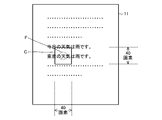
- the pixel size of the code C spreading around the cutout instruction input position F (for example, 40 pixels ⁇ 40 pixel) partial image data is designated.
- the image cutout unit 16 performs subsequent contact input when the arithmetic device 10 detects a specific operation, for example, when an operation button representing “cutout instruction input” preset by the user is selected. You may operate
- a pixel size an example in which partial image data is cut out in units of pixels has been described. Therefore, such a range is referred to as a “pixel size”, but the area of the partial image data (region image) is specified by the number of pixels. It may be specified not only by the case but by other elements.
- the image cutout unit 16 specifies a predetermined range from the partial image data C designated as described above according to the change state of the characteristics of the data in the partial image data C, and this predetermined range. Is extracted as a character display area and cut out. Specifically, the image cutout unit 16 is a predetermined region in the partial image data C along the same direction as the arrangement direction of the character strings existing in the image data determined by the vertical / horizontal determination unit 12. Examine the color change of a row of pixels. That is, here, “color of one row of pixels” is set as “data characteristics”, and the change state is examined. For example, FIG. 6 is an enlarged view of the partial image data indicated by symbol C in FIG.
- whether or not the color of each pixel in the row is the same is determined based on whether or not the value indicating the degree of color change of each pixel in the row is within a preset value range. Do it. For example, when there is little change in the color of each pixel in one column and the value indicating the degree is relatively small, the column is determined as “row spacing” if it is not within the set value range. On the other hand, when the colors of the pixels in one column are not the same and take several values, it is determined that the column is a portion of “character strings” arranged in the horizontal direction. That is, when the color change of each pixel in one column is large and the value indicating the degree is within a relatively large set value range, the column is determined as the “character string” portion.
- the comparison of the color change of the pixel in each column described above may be performed in the direction from the right end to the left end opposite to the signs L1 and L2 in FIG.
- the character string is vertically written, by checking the color change of the pixels in each column from the top to the bottom or from the bottom to the top in the partial image data, Can be specified.
- the image cutout unit 16 performs the determination of the character string portion based on the change in the color of the pixel in the image data, but based on the change state of other characteristics that can be detected from the pixel of the image data. May be.
- the image cutout unit 16 detects “line spacing” based on the color tone change in the partial image data C, that is, the change state of the color of the pixel in one direction in the partial image data C, such as shading or light / dark. May be.
- the image cutout unit 16 is not limited to detecting “inter-row” depending on whether or not the colors of the pixels in one column are the same as described above, and the color tone in one direction in the partial image data C changes.
- such a predetermined area in one direction may be detected as “line spacing”.
- line spacing For example, when a character string is not displayed in the image data, but there is a pattern that follows a certain rule in the background, a certain color change that satisfies a predetermined standard occurs in the color tone of a pixel in one direction. Such a column is detected as “row spacing”.
- the character string recognition unit 17 (character recognition unit) performs character recognition processing on the character display area in the image data passed from the image cutout unit 16 and outputs the resulting character string.
- the character string recognizing unit 17 is not necessarily limited to being provided in the mobile terminal 1 and may be provided in another device. In that case, the portable terminal 1 has only the function of extracting the character display area from the image data as described above, and the extracted character display area is used as another information processing equipped with the character string recognition unit 17. Output to the device.
- the image cutout unit 16 acquires image data from the output data holding unit 13 (step S1) and displays it on the display screen of the input / output device 11.
- image data generally includes color information for displaying each pixel on the screen. Color information displayed as a background when displayed on the screen, and text The information on the color of the part recognized as is different, and can be recognized as a character when the display image is viewed with the eyes.
- the image size determination unit 15 determines the partial image based on the ratio between the physical size of the input / output device 11 stored in the screen information storage unit 14 and the logical size displayed on the display screen of the image data.
- the pixel size to be cut out as data is calculated and acquired by the image cutout unit 16 (step S2).
- the image size determination unit 15 increases the size of the partial image data in accordance with the ratio to the physical size of the display screen when the image data is displayed in an enlarged size from a preset reference. Calculate as follows.
- the arithmetic unit 10 acquires the contact input position and change information of the position by the user from the input / output device 11 (step S3), and from the operation of the contact input (step S4), the character string direction detection process The process proceeds to (Step S5) or image cutout processing (Step S6). For example, when it is determined that the input is a slide input or a flick input according to a change in the contact input position within a predetermined time, the process proceeds to the character string direction detection process in step S5.
- step S5 determines the arrangement direction of the character strings existing in the image data (step S5). For example, when the change information of the contact input position indicates that the vertical direction (vertical direction) is slid, it is determined that the arrangement direction of the character strings existing in the image data is “horizontal direction”, and the contact When the change information of the input position indicates that it slides in the left-right direction (horizontal direction), it is determined that the arrangement direction of the character strings existing in the image data is “vertical direction”.
- the vertical / horizontal determination unit 12 receives the user's contact input acquired from the input / output device 11.
- the arrangement direction of the character strings may be determined using only the latest data from the time-series data of the positions. Thereby, misjudgment can be reduced.
- step S4 (2) If it is determined in step S4 that the contact input is a cutout instruction input (step S4 (2)), the image cutout unit 16 displays image data on the display screen of the input / output device 11 as shown in FIG. If there is a contact input to the input / output device 11 when is displayed, the contact input position F is detected, and the image size range calculated by the image size determination unit 15 with this position F as a reference. The partial image data C is designated. Subsequently, based on the arrangement direction of the character strings existing in the partial image data C determined in step S5, the image cutout unit 16 checks the color of the pixels in each column along the arrangement direction, and determines the character display area. Specify (step S6). Specifically, as described with reference to FIG.
- the image cutout unit 16 outputs the image data portion of the character display area cut out as described above to the character string recognition unit 17 (step S7).
- the character string recognition unit 17 performs character recognition processing on the image data portion of the character display area, and outputs the resulting character string.
- the image data of only the character string portion around the contact input position designated by the user is output to the character string recognition unit 17. For this reason, since the capacity of the image data to be subjected to the character string recognition processing by the character string recognition unit 17 is small and only the necessary character data is subjected to character recognition processing, the characters required by the user can be selected. It can be obtained at high speed. As a result, the efficiency of character recognition processing can be improved, and the practicality of character recognition in an information processing terminal equipped with a touch panel display device can be improved.
- the range for performing the process of specifying the character display area is limited to the range of the partial image data C that is within the pixel size around the contact input position in the image data. Even when there is an image portion other than the character string, the “line spacing” can be specified more effectively. For example, as shown in FIG. 7, when there is an image portion G indicated by oblique lines in addition to a character string in the image data, the “line spacing” specifying process is performed on the entire image data by the method described above. If this is done, there is a high possibility that the colors of the pixels in one column are not the same in the image portion G, so that it is difficult to specify the “line spacing”. However, by performing the inter-line specifying process in the partial image data C as described above, the “inter-line” can be specified avoiding the image part, and the character display area can be determined well.
- the pixel size of the partial image data is calculated in step S2 described above, if the image data is enlarged and displayed on the display screen of the input / output device 11 as shown in FIG.
- the pixel size is calculated to be larger than that described above according to the ratio between the physical size of the device 11 and the logical size displayed on the display screen of the image data. For example, in the case of FIG. 8, when the image data is displayed twice as large as the case of FIG. 5, the physical size of the input / output device 11 and the logical display of the image data are displayed. From the ratio with the size, a pixel size (80 pixels ⁇ 80 pixels) that is twice that of the case of FIG. 5 is calculated. As a result, even if the image data is enlarged / reduced and the character string in the image data is enlarged / reduced, the partial image data in an appropriate range including the desired character string is designated. The character display area can be specified effectively.
- the image size determination unit 15 sets the pixel size of the partial image data in accordance with the ratio between the physical size of the input / output device 11 and the logical size displayed on the image data display screen.
- the pixel size may be set by other methods.
- the image cutout unit 16 may set the pixel size of the partial image data in accordance with the contact area when the operator inputs the image data.
- the image cutout unit 16 sets the pixel size of the partial image data to be larger as the contact area when the character string portion is selected by the operator's finger or the like with respect to the input / output device 11 is larger.
- the image data is enlarged and displayed on the display screen of the input / output device 11, the character string portion is also displayed in a large size, so that the portion of the range including the desired character string portion
- the pixel size of the image data C needs to be set.
- the operator touches the touch panel of the input / output device 11 with a finger over a wider area.
- reference numeral F when a wide area range is contacted as compared with the case of FIG.
- the partial image data C having a pixel size wider than that of FIG. 5 is set accordingly. Is done. Thereafter, the character string partial range is specified in the set partial image data C as described above. Conversely, when the contact area is small, the pixel size of the partial image data is set to be small accordingly.
- the image cutout unit 16 may set the pixel size of the partial image data according to the contact input time by the operator for the input / output device 11. For example, the image cutout unit 16 sets the pixel size of the partial image data to increase as the contact input time when selecting the character string portion is longer.
- the partial image data that is the range for performing the process of specifying the character display area is specified as the pixel size around the contact input position in the image data.
- the partial image data may be specified by a method. For example, when the image cutout unit 16 detects a drag operation after detecting a specific operation indicating “cutout instruction input”, a rectangular region portion having diagonal lines at both ends of the dragged locus is displayed as a partial image. It may be specified as data.
- the image cutout unit 16 determines a rectangular region portion having the two points as diagonal lines. You may specify as image data. Further, when the image cutout unit 16 detects a specific shape figure surrounded by a single line after detecting a specific operation representing “cutout instruction input”, the image cutout unit 16 The range may be specified as partial image data. Note that the method of specifying the partial image data described above is an example, and the partial image data may be specified by any other method.
- the portable terminal 1 in the present embodiment has a configuration that is substantially the same as that of the first embodiment described above, but can perform non-contact input to the input / output device 11, and accordingly, has the following configuration. Take.
- the input / output device 11 (operation input type display device) in the present embodiment includes a panel having an input surface formed on the display surface as described above, and detects a non-contact state of a user's finger or the like with respect to the panel. And has a function of accepting non-contact input. Then, the arithmetic device 10 (control device) detects that a user's finger or the like has come close to a predetermined range of distance from the panel surface, and detects the position on the close panel surface as an operation input position. Then, in accordance with the detected operation input position and the dynamic change in the position, the character string direction detection process, the image segmentation process of the area for character recognition, and the like are performed as in the first embodiment.
- the non-contact input detection method described above is performed, for example, by detecting a change in capacitance in the panel. Specifically, it is detected that contactless input has been made when a change in capacitance occurs with the proximity of the user's finger or the like and the detected capacitance value exceeds a preset threshold value.
- the non-contact input detection method is not limited to the above-described method, and any method may be used.
- the user can operate without directly touching the panel on which the display surface is formed, so that the display surface can be prevented from being stained, and hard parts such as a touch pen and fingernail can be prevented from touching the panel directly. Therefore, the display surface can be prevented from being damaged. As a result, the visibility of the display screen can be improved.
- the input / output device 11 in the present embodiment may have a function of detecting a contact state with respect to the panel, similar to that described in the first embodiment.
- the structure which can detect both an input and a contact input may be sufficient.
- An operation input type display device 101 An operation input type display device 101; A control device 110 that detects an operation input state with respect to the operation input type display device 101 and controls a display state with respect to the operation input type display device 101; The control device 110 includes: An operation input position having a predetermined time length is detected with respect to the operation input type display device 101, and within a preset range with reference to the operation input position in display data displayed on the operation input type display device 101 An image processing unit 111 for designating an image displayed on the screen as a region image, The image processing unit 111 identifies a predetermined range area in the area image according to a change in characteristics of data in the specified area image, and extracts the predetermined range area as a character display area. Information processing terminal 100.
- the control device may further detect a character direction when the operation input to the operation input type display device is accompanied by a dynamic position change, and detects an arrangement direction of character strings existing in the image data based on the position change.
- the image processing unit detects the predetermined region as the line spacing when the predetermined region is a region along the same direction as the arrangement direction of the character strings detected by the character direction detection unit.
- the information processing terminal according to appendix 3 or 4,
- the image processing unit sets the characteristics of the data in the area image to the color tone of each pixel in the area image, and depends on whether or not the change in the color tone of the pixel in the area image is within a predetermined range. Detecting the predetermined region in the region image as the line spacing, Information processing terminal.
- Appendix 6 An information processing terminal according to appendix 5, If the degree of color tone change of the pixel in one improvement in the region image along the arrangement direction of the character strings detected by the character direction detection unit is not within a predetermined range, the image processing unit Determining the predetermined area as the line spacing; Information processing terminal.
- Appendix 7 An information processing terminal according to appendix 6, The image processing unit determines the line spacing located in the same direction and the character string portions located in other columns, and identifies the character string portion sandwiched between the rows as the character display area To Information processing terminal.
- the character direction detection unit detects an arrangement direction of character strings existing in the image data when an operation input accompanied by a dynamic position change with respect to the operation input type display device is continuously generated a plurality of times; Information processing terminal.
- Appendix 9 An information processing terminal according to any one of appendices 1 to 8, The image processing unit, based on a ratio between the size of the display screen of the operation input type display device and the size of the display portion of the display data displayed on the display screen, the area in the display data Specify the area image by setting the area of the image, Information processing terminal.
- Appendix 10 An information processing terminal according to any one of appendices 1 to 9, The image processing unit sets an area of the region image in the display data according to an operation input area for the operation input type display device, and specifies the region image; Information processing terminal.
- the operation input type display device can be input by a touch operation on the display screen of the operation input type display device.
- the control device detects an input state by a touch operation on a display screen of the operation input type display device,
- the image processing unit detects, as the operation input position, a contact input position by a contact operation having a predetermined time length with respect to a display screen of the operation input type display device; Information processing terminal.
- the operation input type display device can be input by a non-contact operation on the display screen of the operation input type display device
- the control device detects an input state by a non-contact operation on a display screen of the operation input type display device
- the image processing unit detects, as the operation input position, a non-contact input position by a non-contact operation that is a predetermined time length with respect to a display screen of the operation input type display device.
- Appendix 13 An information processing terminal according to any one of appendices 1 to 12, The image processing unit outputs the extracted character display area to a character recognition unit that recognizes characters in display data. Information processing terminal.
- An operation input type display device An operation input type display device; A control device that detects an operation input state for the operation input type display device and controls a display state for the operation input type display device; In the control device of the information processing terminal comprising An operation input position having a predetermined time length is detected with respect to the operation input type display device, and is displayed within a preset range with reference to the operation input position in display data displayed on the operation input type display device.
- An image processing unit for designating the processed image as a region image The image processing unit identifies a predetermined area in the area image according to a change in characteristics of data in the specified area image, and extracts the predetermined area as a character display area; A program to make things happen.
- An operation input type display device An operation input type display device; A control device that detects an operation input state for the operation input type display device and controls a display state for the operation input type display device; With an information processing terminal equipped with An operation input position having a predetermined time length is detected with respect to the operation input type display device, and is within a preset range with reference to the operation input type position in display data displayed on the operation input type display device.
- a displayed image is designated as a region image, a predetermined range region in the region image is specified according to a change in characteristics of data in the designated region image, and the predetermined range region is designated as a character display region. Extract as, Image region extraction method.
- the image region extraction method according to attachment 18, comprising: The change state of the characteristics of the data is a state of a color change occurring on the area image. Image region extraction method.
- the programs described in the above embodiments and supplementary notes are stored in a storage device or recorded on a computer-readable recording medium.
- the recording medium is a portable medium such as a flexible disk, an optical disk, a magneto-optical disk, and a semiconductor memory.
Landscapes
- Engineering & Computer Science (AREA)
- Human Computer Interaction (AREA)
- Computer Vision & Pattern Recognition (AREA)
- Physics & Mathematics (AREA)
- General Physics & Mathematics (AREA)
- Multimedia (AREA)
- Theoretical Computer Science (AREA)
- User Interface Of Digital Computer (AREA)
- Telephone Function (AREA)
Abstract
操作入力式表示装置と、操作入力式表示装置に対する操作入力状態を検出すると共に、操作入力式表示装置に対する表示状態を制御する制御装置と、を備え、上記制御装置は、操作入力式表示装置に対し所定時間長となる操作入力位置を検出し、操作入力式表示装置に表示されている表示データ中における操作入力式位置を基準として予め設定された範囲内に表示された画像を領域画像として指定する画像処理部を備え、上記画像処理部は、指定した領域画像内のデータの特性の変化状況に応じて当該領域画像内の所定範囲の領域を特定し、当該所定範囲の領域を文字表示領域として抽出する。
Description
本発明は、情報処理端末にかかり、特に、操作入力式表示装置を備えた情報処理端末に関する。
近年、接触や近接を検出することによる操作入力式入力装置を備えた携帯電話機などの携帯型情報処理端末が普及している。ところが、そのような携帯型情報処理端末では、携帯性などからタッチパネルなどの操作入力式入力装置の物理的なサイズが制約されている。このため、操作入力式入力装置上から利用者が文字を入力する際には、ハードウェア的なキーが装備されている端末と比較して時間がかかる、という問題がある。そして、このような問題から、既に画面上に利用したい文字が表示されている場合には、その文字列を利用可能とすることが要求されている。
一方で、画像から、その画像に含まれる文字を認識する文字認識技術が開発されている。このような技術を用いて、紙やディスプレイなどの媒体に表示された文字列を含む画面を撮像装置によって読み取って画像データ化し、その画像データから文字を認識して文字列に変換し、他のシステムへの入力とする、ということが行われている。これにより、紙やディスプレイなどに表示されている情報を人が読み取って、人手でシステムに入力する手間を省くことができる。
そして、文字認識機能をカメラ付き携帯端末に搭載し、カメラで撮影した画像を文字認識して利用する技術も存在する。このような携帯端末に文字認識技術を搭載した例として、特許文献1に開示の技術がある。特許文献1には、携帯情報機器において、カメラで撮影した画像から文字認識技術を利用して文字を認識し、その文字を利用して携帯情報機器に搭載されている電子辞書からその意味を表示する、という技術が開示されている。
しかしながら、表示部上に表示している画像全体を対象に文字認識を実行して対象の文字列を取得する場合には、文字認識処理に大きな処理能力を必要とし、携帯端末上で実行する場合の処理負荷が増加することとなる。また、操作入力式の入力装置では、画像から文字認識を希望する部分領域を的確に選択することが困難である。従って、携帯端末における文字認識の実用性が低い、という問題が生じる。
このため、本発明の目的は、上述した課題である、文字認識の実用性の低下を解決することができる情報処理端末を提供することにある。
本発明の一形態である情報処理端末は、
操作入力式表示装置と、
前記操作入力式表示装置に対する操作入力状態を検出すると共に、前記操作入力表示装置に対する表示状態を制御する制御装置と、を備え、
前記制御装置は、
前記操作入力式表示装置に対し所定時間長となる操作入力位置を検出し、前記操作入力式表示装置に表示されている表示データ中における前記操作入力位置を基準として予め設定された範囲内に表示された画像を領域画像として指定する画像処理部を備え、
前記画像処理部は、指定した前記領域画像内のデータの特性の変化状況に応じて当該領域画像内の所定範囲の領域を特定し、当該所定範囲の領域を文字表示領域として抽出する、
という構成を取る。
操作入力式表示装置と、
前記操作入力式表示装置に対する操作入力状態を検出すると共に、前記操作入力表示装置に対する表示状態を制御する制御装置と、を備え、
前記制御装置は、
前記操作入力式表示装置に対し所定時間長となる操作入力位置を検出し、前記操作入力式表示装置に表示されている表示データ中における前記操作入力位置を基準として予め設定された範囲内に表示された画像を領域画像として指定する画像処理部を備え、
前記画像処理部は、指定した前記領域画像内のデータの特性の変化状況に応じて当該領域画像内の所定範囲の領域を特定し、当該所定範囲の領域を文字表示領域として抽出する、
という構成を取る。
また、本発明の他の形態であるプログラムは、
操作入力式表示装置と、
前記操作入力式表示装置に対する操作入力状態を検出すると共に、前記操作入力式表示装置に対する表示状態を制御する制御装置と、
を備えた情報処理端末の前記制御装置に、
前記操作入力式表示装置に対し所定時間長となる操作入力位置を検出し、前記操作入力式表示装置に表示されている表示データ中における前記操作入力位置を基準として予め設定された範囲内に表示された画像を領域画像として指定する画像処理部を実現させると共に、
前記画像処理部は、指定した前記領域画像内のデータの特性の変化状況に応じて当該領域画像内の所定範囲の領域を特定し、当該所定範囲の領域を文字表示領域として抽出する、
ことを実現させるためのプログラムである。
操作入力式表示装置と、
前記操作入力式表示装置に対する操作入力状態を検出すると共に、前記操作入力式表示装置に対する表示状態を制御する制御装置と、
を備えた情報処理端末の前記制御装置に、
前記操作入力式表示装置に対し所定時間長となる操作入力位置を検出し、前記操作入力式表示装置に表示されている表示データ中における前記操作入力位置を基準として予め設定された範囲内に表示された画像を領域画像として指定する画像処理部を実現させると共に、
前記画像処理部は、指定した前記領域画像内のデータの特性の変化状況に応じて当該領域画像内の所定範囲の領域を特定し、当該所定範囲の領域を文字表示領域として抽出する、
ことを実現させるためのプログラムである。
また、本発明の他の形態である画像領域抽出方法は、
操作入力式表示装置と、
前記操作入力式表示装置に対する操作入力状態を検出すると共に、前記操作入力式表示装置に対する表示状態を制御する制御装置と、
を備えた情報処理端末にて、
前記操作入力式表示装置に対し所定時間長となる操作入力位置を検出し、前記操作入力式表示装置に表示されている表示データ中における前記操作入力位置を基準として予め設定された範囲内に表示された画像を領域画像として指定し、当該指定した前記領域画像内のデータの特性の変化状況に応じて当該領域画像内の所定範囲の領域を特定し、当該所定範囲の領域を文字表示領域として抽出する、
という構成を取る。
操作入力式表示装置と、
前記操作入力式表示装置に対する操作入力状態を検出すると共に、前記操作入力式表示装置に対する表示状態を制御する制御装置と、
を備えた情報処理端末にて、
前記操作入力式表示装置に対し所定時間長となる操作入力位置を検出し、前記操作入力式表示装置に表示されている表示データ中における前記操作入力位置を基準として予め設定された範囲内に表示された画像を領域画像として指定し、当該指定した前記領域画像内のデータの特性の変化状況に応じて当該領域画像内の所定範囲の領域を特定し、当該所定範囲の領域を文字表示領域として抽出する、
という構成を取る。
本発明は、以上のように構成されることにより、情報処理端末における文字認識の実用性の向上を図ることができる。
<実施形態1>
本発明の第1の実施形態を、図1乃至図9を参照して説明する。図1は、携帯端末の構成を示す機能ブロック図であり、図2は、携帯端末の動作を示すフローチャートである。図3乃至図9は、携帯端末の表示画像の一例を示す図である。
本発明の第1の実施形態を、図1乃至図9を参照して説明する。図1は、携帯端末の構成を示す機能ブロック図であり、図2は、携帯端末の動作を示すフローチャートである。図3乃至図9は、携帯端末の表示画像の一例を示す図である。
[構成]
本発明における携帯端末1は、図1に示すように、タッチパネル型表示装置といった入出力装置11を備えた携帯電話機やタブレット端末などの情報処理端末である。そして、携帯端末1は、装備された演算装置10にプログラムが組み込まれることで構築された、縦横判定部12と、画像サイズ判定部15と、画像切り出し部16と、文字列認識部17と、を備えている。なお、上記プログラムは、予め携帯端末1に装備された記憶装置やネットワークを介して接続された記憶装置、CD-ROMといった可搬媒体などの記憶媒体に記憶されているものである。また、携帯端末1は、装備された記憶装置20に形成された出力データ保持部13と、画像情報記憶部14と、を備えている。なお、出力データ保持部13は、キャッシュメモリや上記画像情報記憶部14の一部に設けられてもよい。以下、各構成について詳述する。
本発明における携帯端末1は、図1に示すように、タッチパネル型表示装置といった入出力装置11を備えた携帯電話機やタブレット端末などの情報処理端末である。そして、携帯端末1は、装備された演算装置10にプログラムが組み込まれることで構築された、縦横判定部12と、画像サイズ判定部15と、画像切り出し部16と、文字列認識部17と、を備えている。なお、上記プログラムは、予め携帯端末1に装備された記憶装置やネットワークを介して接続された記憶装置、CD-ROMといった可搬媒体などの記憶媒体に記憶されているものである。また、携帯端末1は、装備された記憶装置20に形成された出力データ保持部13と、画像情報記憶部14と、を備えている。なお、出力データ保持部13は、キャッシュメモリや上記画像情報記憶部14の一部に設けられてもよい。以下、各構成について詳述する。
上記入出力装置11(操作入力式表示装置)は、上述したようにタッチパネル型表示装置であり、タッチパネル部分にて利用者からの指やタッチペンなどによる接触入力を受け付ける機能と、所定のデータを表示画面部分に表示する機能とを備えている。具体的には、上記入出力装置11を用いることで、携帯端末1に装備された演算装置10(制御装置)が、利用者がタッチパネル型表示装置の表面に触れた位置や接触しながらの動作などの接触状態を検出する。つまり、タッチパネル型表示装置のパネル(表示画面)に対して指が接触したことを検知した場合、当該指が示すと判断したパネル面上の領域を接触入力位置(操作入力位置)として検出する。なお、本実施形態では、入出力装置11がパネルに対する接触を検出して接触入力位置を検出する場合を説明するが、後述する第2の実施形態に記載するように、利用者の指などのパネル面に対する所定距離範囲内への近接状態を検出して、かかる近接したパネル面上の位置を操作入力位置として検出してもよい。また、上記入出力装置11を用いることで、携帯端末1に装備された演算装置10(制御装置)が、出力データ保持部13に記憶されている画像データなどのデータを取得して表示するなど、種々のデータの表示状態を制御する。
上記出力データ保持部13は、携帯端末1が入出力装置11の画面に表示する表示データ(表示データ)を保持している。例えば、表示データは、画像の元データであり、本実施形態では、図3に示すように、文字列が存在する画像データである。そして、画像データの論理的なサイズは、例えば、横方向の幅が480画素であり、縦方向の高さが800画素であることとする。但し、画像データの内容やサイズは、上述したものに限定されない。なお、図3は、後述するように、入出力装置11の表示画面に画像データを表示したときの様子を示している。
上記画面情報記憶部14は、入出力装置11の物理的なサイズを記憶している。本実施形態では、入出力装置11の表示画面の物理的サイズとして、例えば、対角サイズが4inch、という情報を記憶している。また、画面情報記憶部14は、後述するように、入出力装置11の表示画面に表示されている画像データの元の論理的サイズを保持している。但し、本実施形態における入出力装置11の物理的なサイズは、上述した値に限定されない。
ここで、携帯端末1の演算装置10(制御装置)は、上述したように、画像データを入出力装置11の表示画面に表示制御する機能を有しているが、画像データの一部を表示画面全体に拡大して表示する機能や、画像データを縮小して表示画面に表示する機能を有する。なお、画像データの拡大・縮小表示処理は、入出力装置11に対する接触入力による所定の指令に応じて実行される。
上記画像サイズ判定部15は、まず、上述したように入出力装置11の表示画面に画像データが表示されたときにおける、表示画面の物理的サイズと画像データの論理的サイズとの比率を算出する機能を有する。具体的に、画像サイズ判定部15は、入出力装置11の表示画面全体に表示されている画像データの論理的サイズを検出し、当該論理的サイズを表示画面の物理的サイズで除算することで、単位物理的サイズあたりに表示している論理的画素サイズを求めることができる。
そしてさらに、画像サイズ判定部15は、入出力装置11に対する接触入力位置を基準として、算出した表示画面に対する画像データの表示比率に応じた大きさの論理的な画素サイズを求める機能も有する。この画素サイズは、後述するように画像データ内から文字表示領域を抽出するための処理を行う部分画像データのサイズである。
例えば、画像サイズ判定部15は、画像データを拡大することなく入出力装置11の表示画面に表示している場合には、指の接触入力位置を基準として、その周囲に拡大した予め設定された画素サイズを算出する。一方、表示画面に画像データが拡大表示されているときには、その拡大比率に従って、指の接触入力位置を基準として、その周囲に上述した場合よりもさらに広くなる画素サイズを算出する。つまり、入出力装置11の表示画面に対する画像データの拡大表示比率が大きいほど、部分画像データの画素サイズが大きく算出される。
上記縦横判定部12(文字方向検出部)は、演算装置10にて検出された入出力装置11に対する利用者による接触入力が動的な位置変化を伴う場合に、当該位置変化に基づいて、表示されている画像データ内に存在する文字列の並び方向を検出する。つまり、利用者が入力した連続する接触したままの移動動作の方向に応じて、文字列の並び方向を検出する。例えば、利用者によるスライド入力やフリック入力の方向を検出して、文字列の方向を検出するが、この文字列の方向を検出する処理について、図4を参照してさらに詳述する。
まず、縦横判定部12は、入出力装置11に対する利用者による接触入力位置Fの情報を所定時間毎に取得する。そして、図4の矢印に示すように、利用者の接触入力位置Fが上から下に変化している場合、または、下から上に変化している場合、つまり、上下方向にスライド方向が変化している場合には、画像データ内の文字列の表示が「横書き」であると判定する。また、利用者の接触入力位置が左から右、または、右から左に変化している場合、つまり、横方向にスライド方向が変化している場合には、画面上の表示が「縦書き」であると判定する。具体的には、所定時間内において接触入力を検知した領域の変化が生じた場合、その変化量を表示画面の左右方向に対応するx方向成分、上下方向に対応するy方向成分に分解し、いずれの方向成分の変化量が多いかを算出する。そして、x方向成分の変化量の方が多い場合には、表示画面に表示された文字列の並びの方向は縦書きであると判断し、y方向成分の変化量の方が多い場合には、表示画面に表示された文字列の並びの方向は横書きであると判断する。
以上のように、利用者の接触入力位置の変化から、入出力装置11に表示されている画像データ中の文字列の方向を判定できる理由は、以下の通りである。携帯端末1から利用者に表示したい情報があり、その情報全部を一度に画面上に表示しようとすると、画面上の物理的な文字のサイズが小さくなりすぎてしまい、利用者にとって読むことができなくなる場合がある。たとえば、そのような情報の例としては、長い文章や電子的な書籍などがある。この場合において、表示したい情報を画像化して携帯端末のメモリ上に保持しておき、その画像のうちの一部分を画面上の全体に表示することが良く行われる。利用者は、入出力装置11上で操作をすることにより、表示する画像部分を縦または横に移動して、画像全体を入出力装置11上で閲覧する。そして、このような場合の利用者の入出力装置11上での操作として、文字列が横書きである場合には、入出力装置11上で下から上、又は、上から下に接触位置を移動させることによって、表示をスクロールさせる可能性が高い。これは、文字列が横書きである場合には、物理的な画面幅内で改行するように表示し、画面サイズ内に表示されている文字列が文として途切れないようにしているのが一般的であり、この場合において、画面内に表示されていない部分を見る場合には、上下方向に画面を移動するように操作するのが一般的であるからである。
例えば、図4に示すように、上下にそれぞれ位置する点線で挟まれている部分が実際に入出力装置11上に表示されている部分であるとすると、接触入力位置Fを上下方向の矢印に示す方向に操作することにより、画像データ自体を矢印S方向にスクロールさせることができ、画像全体の上方部分、または、下方部分を表示することができる。
逆に、文字列が縦書きである場合には、入出力装置11上で左から右、または、右から左に接触位置を移動させることによって表示をスクロールさせる可能性が高い。これは、文字列が縦書ききである場合には、物理的な画面高さの範囲内で改行するように表示し、画面サイズ内に表示されている文字列が文として途切れないようにしているのが一般的であり、この場合において、画面内に表示されていない部分を見る場合には、左右方向に画面を移動するように操作するのが一般的であるからである。
以上のことを利用して、縦横判定部12は、利用者の指し示す位置、つまり、接触入力位置の変化を時系列的に観測し、直近の所定時間内における縦方向の位置の変化の回数が多い場合には、文字列を「横書き」、横方向の位置の変化の回数が多い場合には文字列を「縦書き」と判定する。なお、縦横判定部12は、所定方向(縦方向、あるいは、横方向)への動的な位置変化を伴う接触入力が、所定時間内に複数回連続して生じた場合に、かかる方向に対応する文字列の並び方向を判定してもよい。このとき、その時間や回数は、予め設定されていることとする。
上記画像切り出し部(画像処理部)16は、入出力装置11の表示画面で画像データが表示されているときに、演算装置10にて検出された入出力装置11に対する接触入力位置の変化が所定時間内にない場合、もしくは、接触入力位置の変化量が所定領域の範囲内で留まる場合、つまり、所定位置に対する所定時間長の接触入力を検出した場合には、この接触入力を画像切り出し指示と判断する。そして、画像切り出し指示を検出すると、画像切り出し部16は、このときの接触入力位置を検出し、この位置を基準として上述したように画像サイズ判定部15にて算出された画素サイズの範囲の部分画像データ(領域画像)を指定する。ここで、上述した画像切り出し指示を表す接触入力を、「切り出し指示入力」と称する。
具体的に、図5に示すように、符号Fが指による切り出し指示入力を示す位置であるとすると、この切り出し指示入力位置Fを中心として周囲に広がる符号Cの画素サイズ(例えば、40画素×40画素)の部分画像データを指定する。なお、画像切り出し部16は、例えば、利用者にて予め設定された「切り出し指示入力」を表す操作ボタンが選択されるなど、特定の操作を演算装置10が検出した場合に、その後の接触入力位置を基準として部分画像データを指定するよう作動してもよい。なお、上記では、部分画像データを画素単位で切り出す例を説明しているため、かかる範囲を「画素サイズ」と称しているが、部分画像データ(領域画像)の面積は、画素数によって特定される場合に限らず、その他の要素によって特定されてもよい。
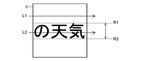
さらに、上記画像切り出し部16は、上述したように指定した部分画像データC内から、かかる部分画像データC内のデータの特性の変化状況に応じて、所定範囲の領域を特定し、この所定範囲の領域を文字表示領域として抽出して切り出す。具体的に、画像切り出し部16は、まず、部分画像データC内において、上記縦横判定部12にて判定した画像データ内に存在する文字列の並び方向と同じ方向に沿った所定の領域である一列の画素の色の変化を調べる。つまり、ここでは、「一列の画素の色」を「データの特性」として、その変化状況を調べる。例えば、図6は、図5の符号Cで示した部分画像データの拡大図であるが、画像データ中の文字列の並び方向が横方向であると判定されている場合には、符号L1やL2に示すように、横方向の所定の領域である各列において、それぞれ各画素の色の変化を調べる。そして、一列中におけるが各画素の色が同一である場合には、その列は横方向に並んだ文字列と文字列との間に位置する「行間」であると判定する。
なお、上述した一列中における各画素の色が同一であるか否かの判定は、一列中の各画素の色の変化の度合いを表す値が、予め設定された値の範囲内にあるか否かで行う。例えば、一列中に各画素の色の変化が少なく、その度合いを表す値が比較的小さいため設定値の範囲内にない場合には、かかる列を「行間」として判定する。一方、一列中の画素の色が同一ではなくいくつかの値をとる場合には、その列は横方向に並んだ「文字列」の部分であると判定する。つまり、一列中に各画素の色の変化が大きく、その度合いを表す値が比較的大きい設定値の範囲内にある場合に、かかる列を「文字列」の部分として判定する。そして、上述した判定を全ての列で行うことで、一方向における文字列部分の上端と下端との間の領域(図6のR1とR2の間の部分)、つまり、「行間」と判定された列に挟まれた領域を特定し、かかる領域を文字表示領域として特定して切り出す。
なお、文字列が横書きである場合には、上述した各列における画素の色の変化の比較は、図6の符号L1,L2とは逆の右端から左端に向かう方向で行ってもよい。また、文字列が縦書きである場合には、部分画像データ内で上方から下方、あるいは、下方から上方に向かって、各列の画素の色の変化を調べることで、縦書き文字列の行間を特定することができる。
ここで、画像切り出し部16は、文字列部分の判定を、画像データ中の画素の色の変化に基づいて行ったが、画像データの画素から検出可能な他の特性の変化状況に基づいて行ってもよい。例えば、画像切り出し部16は、部分画像データC内の色調変化、つまり、部分画像データC内の一方向に亘る画素の色の濃淡、明暗などの変化の状況に基づいて、「行間」を検出してもよい。このとき、画像切り出し部16は、上述したように一列中の画素の色が同一か否かによって「行間」を検出することに限定されず、部分画像データC内の一方向における色調に変化が生じている場合に、かかる一方向の所定の領域を「行間」として検出してもよい。例えば、画像データ中に文字列が表示されていないが、背景に一定の規則に沿った模様がある場合には、一方向における画素の色調に予め定めた基準を満たす一定の色調変化が生じているときに、かかる列を「行間」として検出する。
そして、上記文字列認識部17(文字認識部)は、画像切り出し部16から渡された画像データ中の文字表示領域に対して文字認識処理を行い、その結果の文字列を出力する。但し、文字列認識部17は、必ずしも携帯端末1に装備されていることに限定されず、他の装置に装備されていてもよい。その場合には、携帯端末1は、上述したように画像データから文字表示領域を抽出する機能のみを有しており、この抽出した文字表示領域を文字列認識部17を装備した他の情報処理装置に出力する。
[動作]
次に、上述した携帯端末1による画像データから文字認識を行うときの動作を、図2のフローチャートを参照して説明する。
次に、上述した携帯端末1による画像データから文字認識を行うときの動作を、図2のフローチャートを参照して説明する。
まず、画像切り出し部16は、出力データ保持部13から画像データを取得して(ステップS1)、入出力装置11の表示画面に表示する。このとき、図3に示すように、論理的なサイズが横方向の幅が480画素、縦方向の高さが800画素の画像データが、表示画面全体に表示されていることとする。また、画像データは、それぞれの画素について画面上に表示するときの色の情報が含まれているのが一般的であり、画面上で表示したときに背景として表示される色の情報と、文字として認識される部分の色の情報は別のものとなっており、表示画像を目で見たときに、文字として認識することができることとする。
続いて、画像サイズ判定部15が、画面情報記憶部14に記憶されている入出力装置11の物理的サイズと、画像データの表示画面に表示されている論理的サイズとの比率から、部分画像データとして切り出す画素サイズを算出し、画像切り出し部16が取得する(ステップS2)。このとき、画像サイズ判定部15は、画像データが予め設定された基準よりも拡大表示されている場合には、表示画面の物理サイズとの比率に対応して、部分画像データのサイズが広くなるよう算出する。
続いて、演算装置10は、入出力装置11から利用者による接触入力位置及びその位置の変化情報を取得し(ステップS3)、その接触入力の動作から(ステップS4)、文字列方向の検出処理(ステップS5)、あるいは、画像切り出し処理(ステップS6)に進む。例えば、接触入力位置の所定時間内における変化に応じて、スライド入力やフリック入力と判断された場合には、ステップS5の文字列方向の検出処理に進む。一方、接触入力位置の変化が所定時間内にない、もしくは、接触入力位置の変化量が所定領域の範囲内で留まり、切り出し指示入力と判断された場合には、ステップS6の画像切り出し処理に進む。
上記ステップS4により、接触入力がスライド入力やフリック入力と判断された場合には(ステップS4で(1))、縦横判定部12が画像データ内に存在する文字列の並び方向を判定する(ステップS5)。例えば、接触入力位置の変化情報が上下方向(縦方向)にスライドしていることを示す場合には、画像データ内に存在する文字列の並び方向が「横方向」であると判定し、接触入力位置の変化情報が左右方向(横方向)にスライドしていることを示す場合には、画像データ内に存在する文字列の並び方向が「縦方向」であると判定する。
なお、利用者が携帯端末1を操作している間に表示される画像データが別の画像データに切り替わる場合もあるため、縦横判定部12は、入出力装置11から取得する利用者の接触入力位置の時系列データの中から直近のデータのみを利用して、文字列の並び方向を判定してもよい。これにより、誤判定を軽減させることができる。
上記ステップS4により、接触入力が切り出し指示入力と判断された場合には(ステップS4で(2))、画像切り出し部16は、図5に示すように、入出力装置11の表示画面で画像データが表示されているときに入出力装置11に対して接触入力があると、かかる接触入力位置Fを検出し、この位置Fを基準として、画像サイズ判定部15にて算出された画像サイズの範囲の部分画像データCを指定する。続いて、画像切り出し部16は、ステップS5において判定した部分画像データC内に存在する文字列の並び方向に基づいて、その並び方向に沿った各列の画素の色を調べ、文字表示領域を特定する(ステップS6)。具体的には、図6を参照して説明したように、部分画像データC内において、一列中におけるが画素の色が同一である「行間」と、一列中におけるが画素の色が同一ではなくいくつかの値をとる「文字列」部分とを特定し、「行間」に挟まれた領域を文字表示領域として特定し、かかる画像データ部分を切り出す。
続いて、画像切り出し部16は、上述したように切り出した文字表示領域の画像データ部分を文字列認識部17に出力する(ステップS7)。すると、文字列認識部17は、文字表示領域の画像データ部分に対する文字認識処理を行い、その結果の文字列を出力する。
以上のように、本発明によると、利用者が指示した接触入力位置周辺の文字列部分のみの画像データを文字列認識部17に出力している。このため、文字列認識部17による文字列認識処理の対象となる画像データの容量が小さく、かつ、必要な文字データのみの文字認識処理を行うこととなるため、利用者が必要とする文字を高速に得ることができる。その結果、文字認識処理の効率化を図ることができ、タッチパネル型表示装置を備えた情報処理端末における文字認識の実用性の向上を図ることができる。
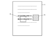
また、上述したように、文字表示領域を特定する処理を行う範囲を、画像データ中の接触入力位置の周辺の画素サイズ内である部分画像データCの範囲に限定することで、画像データ内に文字列以外に画像部分が存在している場合であっても、より有効に「行間」を特定することができる。例えば、図7に示すように、画像データ内に文字列の他に斜線で示す画像部分Gが存在している場合には、画像データ全体に対して上述した方法により「行間」の特定処理を行うと、画像部分Gでは一列の画素の色が同一ではない可能性が高いため、「行間」を特定することが困難となる。しかし、上述したように部分画像データC内で行間の特定処理を行うことで、画像部分を避けて「行間」を特定でき、文字表示領域を良好に判定することができる。
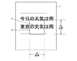
ここで、上述したステップS2で部分画像データの画素サイズを算出する際に、図8に示すように画像データが入出力装置11の表示画面に対して拡大表示されている場合には、入出力装置11の物理的サイズと、画像データの表示画面に表示されている論理的サイズとの比率に応じて、上述した場合よりも大きくなるよう画素サイズを算出する。例えば、図8の場合に、図5の場合と比較して2倍の大きさで画像データが表示されている場合には、入出力装置11の物理サイズと画像データの表示されている論理的サイズとの比率から、図5の場合よりも2倍の画素サイズ(80画素×80画素)が算出される。これにより、画像データが拡大・縮小表示されており、当該画像データ内の文字列が拡大・縮小表示されている場合であっても、所望の文字列を含む適切な範囲の部分画像データを指定することができ、有効に文字表示領域を特定することができる。
また、上記では、画像サイズ判定部15にて入出力装置11の物理的サイズと画像データの表示画面に表示されている論理的サイズとの比率に応じて部分画像データの画素サイズを設定していたが、他の方法にて画素サイズを設定してもよい。例えば、画像切り出し部16にて、画像データに対する操作者による接触入力時における接触面積に応じて、部分画像データの画素サイズを設定してもよい。
一例として、画像切り出し部16が、入出力装置11に対する操作者の指などによる文字列部分の選択時における接触面積が大きいほど、部分画像データの画素サイズが大きくなるよう設定する。例えば、図9に示すように、入出力装置11の表示画面に画像データが拡大表示されている場合には、文字列部分も大きく表示されるため、所望の文字列部分が含まれる範囲の部分画像データCの画素サイズが設定される必要がある。このような場合に、操作者は入出力装置11のタッチパネルに対してより広い面積で指を接触させる。このとき、符号Fに示すように、図5の場合と比較して広い面積の範囲が接触されると、これに応じて図5の場合よりも広い範囲の画素サイズの部分画像データCが設定される。その後は、設定された部分画像データC内で上述したように文字列部分範囲の特定を行う。なお、逆に接触面積が小さい場合には、それに応じて部分画像データの画素サイズを小さく設定する。
また、上述した例とは異なり、画像切り出し部16にて、入出力装置11に対する操作者による接触入力時間に応じて、部分画像データの画素サイズを設定してもよい。例えば、画像切り出し部16が、文字列部分の選択時における接触入力時間が長いほど、部分画像データの画素サイズが大きくなるよう設定する。
また、上記では(例えば、ステップS6)、文字表示領域を特定する処理を行う範囲である部分画像データを、画像データ中の接触入力位置の周辺の画素サイズ内として特定していたが、他の方法にて部分画像データを特定してもよい。例えば、画像切り出し部16が、「切り出し指示入力」を表す特定の操作を検出した後にドラッグ操作を検出した場合には、かかるドラッグ操作された軌跡の両端を対角線とする矩形領域部分を、部分画像データとして特定してもよい。
あるいは、画像切り出し部16は、「切り出し指示入力」を表す特定の操作を検出した後に2点の接触入力位置を検出した場合には、かかる2点の位置を対角線とする矩形領域部分を、部分画像データとして特定してもよい。さらに、画像切り出し部16は、「切り出し指示入力」を表す特定の操作を検出した後に、1本の線で囲われた所定形状の図形の入力を検出した場合には、かかる所定形状の図形の範囲内を部分画像データとして特定してもよい。なお、上述した部分画像データを特定する方法は一例であって、他のいかなる方法で部分画像データを特定してもよい。
<実施形態2>
次に、本発明の第2の実施形態を説明する。本実施形態における携帯端末1は、上述した実施形態1とほぼ同様の構成をとっているが、入出力装置11に対して非接触入力が可能であり、これに伴い、以下のような構成をとる。
次に、本発明の第2の実施形態を説明する。本実施形態における携帯端末1は、上述した実施形態1とほぼ同様の構成をとっているが、入出力装置11に対して非接触入力が可能であり、これに伴い、以下のような構成をとる。
本実施形態における入出力装置11(操作入力式表示装置)は、上述同様に表示面に入力面が形成されたパネルを備えており、当該パネルに対する利用者の指などの非接触状態を検出して、非接触入力を受け付ける機能を有する。そして、演算装置10(制御装置)は、利用者の指などがパネル面に対して所定範囲の距離に近接したことを検出し、近接したパネル面上における位置を操作入力位置として検出する。そして、この検出した操作入力位置やその位置の動的な変化に応じて、上述した実施形態1と同様に、文字列方向の検出処理や文字認識を行う領域の画像切り出し処理などを行う。
ここで、上述した非接触入力の検出方法としては、例えば、パネルにおける静電容量の変化を検出することで行う。具体的には、利用者の指などの近接に伴い、静電容量の変化が生じ、検出した静電容量の値が予め設定された閾値を超えた場合に、非接触入力されたと検出する。但し、非接触入力の検出方法は、上述した方法に限定されず、いかなる方法で行ってもよい。
上記構成により、利用者は、表示面が形成されたパネルに直接触れずに操作できるため、表示面が汚れることを抑制でき、また、タッチペンや指の爪などの硬質部位もパネルに直接触れずに操作できるため、表示面に傷がつくことも抑制できる。その結果、表示画面の視認性の向上を図ることができる。
なお、本実施形態における入出力装置11は、実施形態1で説明したものと同様に、パネルに対する接触状態を検出する機能を有していてもよく、これに伴い、演算装置10は、非接触入力及び接触入力のいずれも検出可能な構成であってもよい。
<付記>
上記実施形態の一部又は全部は、以下の付記のようにも記載されうる。以下、本発明における情報処理端末(図10参照)、プログラム、画像領域抽出方法の構成の概略を説明する。但し、本発明は、以下の構成に限定されない。
上記実施形態の一部又は全部は、以下の付記のようにも記載されうる。以下、本発明における情報処理端末(図10参照)、プログラム、画像領域抽出方法の構成の概略を説明する。但し、本発明は、以下の構成に限定されない。
(付記1)
操作入力式表示装置101と、
前記操作入力式表示装置101に対する操作入力状態を検出すると共に、前記操作入力式表示装置101に対する表示状態を制御する制御装置110と、を備え、
前記制御装置110は、
前記操作入力式表示装置101に対し所定時間長となる操作入力位置を検出し、前記操作入力式表示装置101に表示されている表示データ中における前記操作入力位置を基準として予め設定された範囲内に表示された画像を領域画像として指定する画像処理部111を備え、
前記画像処理部111は、指定した前記領域画像内のデータの特性の変化状況に応じて当該領域画像内の所定範囲の領域を特定し、当該所定範囲の領域を文字表示領域として抽出する、
情報処理端末100。
操作入力式表示装置101と、
前記操作入力式表示装置101に対する操作入力状態を検出すると共に、前記操作入力式表示装置101に対する表示状態を制御する制御装置110と、を備え、
前記制御装置110は、
前記操作入力式表示装置101に対し所定時間長となる操作入力位置を検出し、前記操作入力式表示装置101に表示されている表示データ中における前記操作入力位置を基準として予め設定された範囲内に表示された画像を領域画像として指定する画像処理部111を備え、
前記画像処理部111は、指定した前記領域画像内のデータの特性の変化状況に応じて当該領域画像内の所定範囲の領域を特定し、当該所定範囲の領域を文字表示領域として抽出する、
情報処理端末100。
(付記2)
付記1に記載の情報処理端末であって、
前記データの特性の変化状況は、前記領域画像上で生じている色調変化の状況である、
情報処理端末。
付記1に記載の情報処理端末であって、
前記データの特性の変化状況は、前記領域画像上で生じている色調変化の状況である、
情報処理端末。
(付記3)
付記2に記載の情報処理端末であって、
前記画像処理部は、前記領域画像において前記色調変化が一方向に亘って生じている場合に、その所定の領域を行間として検出し、当該検出した行間以外の領域を前記文字表示領域として抽出する、
情報処理端末。
付記2に記載の情報処理端末であって、
前記画像処理部は、前記領域画像において前記色調変化が一方向に亘って生じている場合に、その所定の領域を行間として検出し、当該検出した行間以外の領域を前記文字表示領域として抽出する、
情報処理端末。
(付記4)
付記3に記載の情報処理端末であって、
前記制御装置は、さらに、前記操作入力式表示装置に対する操作入力が動的な位置変化を伴う場合、当該位置変化に基づいて前記画像データ内に存在する文字列の並び方向を検出する文字方向検出部を備え、
前記画像処理部は、前記所定の領域が、前記文字方向検出部にて検出した文字列の並び方向と同じ方向に沿った領域である場合に、当該所定の領域を前記行間として検出する、
情報処理端末。
付記3に記載の情報処理端末であって、
前記制御装置は、さらに、前記操作入力式表示装置に対する操作入力が動的な位置変化を伴う場合、当該位置変化に基づいて前記画像データ内に存在する文字列の並び方向を検出する文字方向検出部を備え、
前記画像処理部は、前記所定の領域が、前記文字方向検出部にて検出した文字列の並び方向と同じ方向に沿った領域である場合に、当該所定の領域を前記行間として検出する、
情報処理端末。
(付記5)
付記3又は4に記載の情報処理端末であって、
前記画像処理部は、前記領域画像内のデータの特性を、当該領域画像内の画素それぞれの色調とし、当該領域画像内の画素の色調の変化が所定の範囲内であるか否かにに応じて、当該領域画像内の前記所定の領域を前記行間として検出する、
情報処理端末。
付記3又は4に記載の情報処理端末であって、
前記画像処理部は、前記領域画像内のデータの特性を、当該領域画像内の画素それぞれの色調とし、当該領域画像内の画素の色調の変化が所定の範囲内であるか否かにに応じて、当該領域画像内の前記所定の領域を前記行間として検出する、
情報処理端末。
(付記6)
付記5に記載の情報処理端末であって、
前記画像処理部は、前記文字方向検出部にて検出した文字列の並び方向に沿った前記領域画像内の一方向上における画素の色調変化の度合いが所定の範囲内にない場合、当該領域画像内の前記所定の領域を前記行間として判定する、
情報処理端末。
付記5に記載の情報処理端末であって、
前記画像処理部は、前記文字方向検出部にて検出した文字列の並び方向に沿った前記領域画像内の一方向上における画素の色調変化の度合いが所定の範囲内にない場合、当該領域画像内の前記所定の領域を前記行間として判定する、
情報処理端末。
(付記7)
付記6に記載の情報処理端末であって、
前記画像処理部は、同一方向上に位置する前記行間と、それ以外の列に位置する文字列部分と、を判定し、前記行間に挟まれた前記文字列部分を、前記文字表示領域として特定する、
情報処理端末。
付記6に記載の情報処理端末であって、
前記画像処理部は、同一方向上に位置する前記行間と、それ以外の列に位置する文字列部分と、を判定し、前記行間に挟まれた前記文字列部分を、前記文字表示領域として特定する、
情報処理端末。
(付記8)
付記4乃至7のいずれかに記載の情報処理端末であって、
前記文字方向検出部は、前記操作入力式表示装置に対する動的な位置変化を伴う操作入力が複数回連続して生じた場合に、前記画像データ内に存在する文字列の並び方向を検出する、
情報処理端末。
付記4乃至7のいずれかに記載の情報処理端末であって、
前記文字方向検出部は、前記操作入力式表示装置に対する動的な位置変化を伴う操作入力が複数回連続して生じた場合に、前記画像データ内に存在する文字列の並び方向を検出する、
情報処理端末。
(付記9)
付記1乃至8のいずれかに記載の情報処理端末であって、
前記画像処理部は、前記操作入力式表示装置の表示画面のサイズと、当該表示画面に表示されている前記表示データの表示部分のサイズと、の比率に基づいて、前記表示データ中の前記領域画像の面積を設定して、当該領域画像を指定する、
情報処理端末。
付記1乃至8のいずれかに記載の情報処理端末であって、
前記画像処理部は、前記操作入力式表示装置の表示画面のサイズと、当該表示画面に表示されている前記表示データの表示部分のサイズと、の比率に基づいて、前記表示データ中の前記領域画像の面積を設定して、当該領域画像を指定する、
情報処理端末。
(付記10)
付記1乃至9のいずれかに記載の情報処理端末であって、
前記画像処理部は、前記操作入力式表示装置に対する操作入力面積に応じて前記表示データ中の前記領域画像の面積を設定して、当該領域画像を指定する、
情報処理端末。
付記1乃至9のいずれかに記載の情報処理端末であって、
前記画像処理部は、前記操作入力式表示装置に対する操作入力面積に応じて前記表示データ中の前記領域画像の面積を設定して、当該領域画像を指定する、
情報処理端末。
(付記11)
付記1乃至10のいずれかに記載の情報処理端末であって、
前記操作入力式表示装置は、当該操作入力式表示装置の表示面画面に対する接触操作による入力が可能であり、
前記制御装置は、前記操作入力式表示装置の表示画面に対する接触操作による入力状態を検出し、
前記画像処理部は、前記操作入力式表示装置の表示画面に対し所定時間長となる接触操作による接触入力位置を前記操作入力位置として検出する、
情報処理端末。
付記1乃至10のいずれかに記載の情報処理端末であって、
前記操作入力式表示装置は、当該操作入力式表示装置の表示面画面に対する接触操作による入力が可能であり、
前記制御装置は、前記操作入力式表示装置の表示画面に対する接触操作による入力状態を検出し、
前記画像処理部は、前記操作入力式表示装置の表示画面に対し所定時間長となる接触操作による接触入力位置を前記操作入力位置として検出する、
情報処理端末。
(付記12)
付記1乃至11のいずれかに記載の情報処理端末であって、
前記操作入力式表示装置は、当該操作入力式表示装置の表示画面に対する非接触操作による入力が可能であり、
前記制御装置は、前記操作入力式表示装置の表示画面に対する非接触操作による入力状態を検出し、
前記画像処理部は、前記操作入力式表示装置の表示画面に対し所定時間長となる非接触操作による非接触入力位置を前記操作入力位置として検出する、
情報処理端末。
付記1乃至11のいずれかに記載の情報処理端末であって、
前記操作入力式表示装置は、当該操作入力式表示装置の表示画面に対する非接触操作による入力が可能であり、
前記制御装置は、前記操作入力式表示装置の表示画面に対する非接触操作による入力状態を検出し、
前記画像処理部は、前記操作入力式表示装置の表示画面に対し所定時間長となる非接触操作による非接触入力位置を前記操作入力位置として検出する、
情報処理端末。
(付記13)
付記1乃至12のいずれかに記載の情報処理端末であって、
前記画像処理部は、抽出した前記文字表示領域を、表示データ内の文字を認識する文字認識部に出力する、
情報処理端末。
付記1乃至12のいずれかに記載の情報処理端末であって、
前記画像処理部は、抽出した前記文字表示領域を、表示データ内の文字を認識する文字認識部に出力する、
情報処理端末。
(付記14)
付記13に記載の情報処理端末であって、
前記制御装置は、前記文字認識部を有する、
情報処理端末。
付記13に記載の情報処理端末であって、
前記制御装置は、前記文字認識部を有する、
情報処理端末。
(付記15)
操作入力式表示装置と、
前記操作入力式表示装置に対する操作入力状態を検出すると共に、前記操作入力式表示装置に対する表示状態を制御する制御装置と、
を備えた情報処理端末の前記制御装置に、
前記操作入力式表示装置に対し所定時間長となる操作入力位置を検出し、前記操作入力式表示装置に表示されている表示データ中における前記操作入力位置を基準として予め設定された範囲内に表示された画像を領域画像として指定する画像処理部を実現させると共に、
前記画像処理部は、指定した前記領域画像内のデータの特性の変化状況に応じて当該領域画像内の所定範囲の領域を特定し、当該所定範囲の領域を文字表示領域として抽出する、
ことを実現させるためのプログラム。
操作入力式表示装置と、
前記操作入力式表示装置に対する操作入力状態を検出すると共に、前記操作入力式表示装置に対する表示状態を制御する制御装置と、
を備えた情報処理端末の前記制御装置に、
前記操作入力式表示装置に対し所定時間長となる操作入力位置を検出し、前記操作入力式表示装置に表示されている表示データ中における前記操作入力位置を基準として予め設定された範囲内に表示された画像を領域画像として指定する画像処理部を実現させると共に、
前記画像処理部は、指定した前記領域画像内のデータの特性の変化状況に応じて当該領域画像内の所定範囲の領域を特定し、当該所定範囲の領域を文字表示領域として抽出する、
ことを実現させるためのプログラム。
(付記16)
付記15に記載のプログラムであって、
前記データの特性の変化状況は、前記領域画像上で生じている色調変化の状況である、
プログラム。
付記15に記載のプログラムであって、
前記データの特性の変化状況は、前記領域画像上で生じている色調変化の状況である、
プログラム。
(付記17)
付記16に記載のプログラムであって、
前記画像処理部は、前記領域画像において前記色調変化が一方向に亘って生じている場合に、その所定の領域を行間として検出し、当該検出した行間以外の領域を前記文字表示領域として抽出する、
プログラム。
付記16に記載のプログラムであって、
前記画像処理部は、前記領域画像において前記色調変化が一方向に亘って生じている場合に、その所定の領域を行間として検出し、当該検出した行間以外の領域を前記文字表示領域として抽出する、
プログラム。
(付記18)
操作入力式表示装置と、
前記操作入力式表示装置に対する操作入力状態を検出すると共に、前記操作入力式表示装置に対する表示状態を制御する制御装置と、
を備えた情報処理端末にて、
前記操作入力式表示装置に対し所定時間長となる操作入力位置を検出し、前記操作入力式表示装置に表示されている表示データ中における前記操作入力式位置を基準として予め設定された範囲内に表示された画像を領域画像として指定し、当該指定した前記領域画像内のデータの特性の変化状況に応じて当該領域画像内の所定範囲の領域を特定し、当該所定範囲の領域を文字表示領域として抽出する、
画像領域抽出方法。
操作入力式表示装置と、
前記操作入力式表示装置に対する操作入力状態を検出すると共に、前記操作入力式表示装置に対する表示状態を制御する制御装置と、
を備えた情報処理端末にて、
前記操作入力式表示装置に対し所定時間長となる操作入力位置を検出し、前記操作入力式表示装置に表示されている表示データ中における前記操作入力式位置を基準として予め設定された範囲内に表示された画像を領域画像として指定し、当該指定した前記領域画像内のデータの特性の変化状況に応じて当該領域画像内の所定範囲の領域を特定し、当該所定範囲の領域を文字表示領域として抽出する、
画像領域抽出方法。
(付記19)
付記18に記載の画像領域抽出方法であって、
前記データの特性の変化状況は、前記領域画像上で生じている色調変化の状況である、
画像領域抽出方法。
付記18に記載の画像領域抽出方法であって、
前記データの特性の変化状況は、前記領域画像上で生じている色調変化の状況である、
画像領域抽出方法。
(付記20)
付記19に記載の画像領域抽出方法であって、
前記領域画像において前記色調変化が一方向に亘って生じている場合に、その所定の領域を行間として検出し、当該検出した行間以外の領域を前記文字表示領域として抽出する、
画像領域抽出方法。
付記19に記載の画像領域抽出方法であって、
前記領域画像において前記色調変化が一方向に亘って生じている場合に、その所定の領域を行間として検出し、当該検出した行間以外の領域を前記文字表示領域として抽出する、
画像領域抽出方法。
なお、上記各実施形態や付記で記載したプログラムは、記憶装置に記憶されていたり、コンピュータが読み取り可能な記録媒体に記録されている。例えば、記録媒体は、フレキシブルディスク、光ディスク、光磁気ディスク、及び、半導体メモリ等の可搬性を有する媒体である。
以上、上記各実施形態を参照して本願発明を説明したが、本願発明は、上述した実施形態に限定されるものではない。本願発明の構成や詳細には、本願発明の範囲内で当業者が理解しうる様々な変更をすることができる。
なお、本発明は、日本国にて2011年9月26日に特許出願された特願2011-208566の特許出願に基づく優先権主張の利益を享受するものであり、当該特許出願に記載された内容は、全て本明細書に含まれるものとする。
1 携帯端末
10 演算装置
11 入出力装置
12 縦横判定部
13 出力データ保持部
14 画像情報記憶部
15 画像サイズ判定部
16 画像切り出し部
17 文字列認識部
20 記憶装置
100 情報処理端末
101 操作入力式表示装置
110 制御装置
111 画像処理部
10 演算装置
11 入出力装置
12 縦横判定部
13 出力データ保持部
14 画像情報記憶部
15 画像サイズ判定部
16 画像切り出し部
17 文字列認識部
20 記憶装置
100 情報処理端末
101 操作入力式表示装置
110 制御装置
111 画像処理部
Claims (20)
- 操作入力式表示装置と、
前記操作入力式表示装置に対する操作入力状態を検出すると共に、前記操作入力式表示装置に対する表示状態を制御する制御装置と、を備え、
前記制御装置は、
前記操作入力式表示装置に対し所定時間長となる操作入力位置を検出し、前記操作入力式表示装置に表示されている表示データ中における前記操作入力位置を基準として予め設定された範囲内に表示された画像を領域画像として指定する画像処理部を備え、
前記画像処理部は、指定した前記領域画像内のデータの特性の変化状況に応じて当該領域画像内の所定範囲の領域を特定し、当該所定範囲の領域を文字表示領域として抽出する、
情報処理端末。 - 請求項1に記載の情報処理端末であって、
前記データの特性の変化状況は、前記領域画像上で生じている色調変化の状況である、
情報処理端末。 - 請求項2に記載の情報処理端末であって、
前記画像処理部は、前記領域画像において前記色調変化が一方向に亘って生じている場合に、その所定の領域を行間として検出し、当該検出した行間以外の領域を前記文字表示領域として抽出する、
情報処理端末。 - 請求項3に記載の情報処理端末であって、
前記制御装置は、さらに、前記操作入力式表示装置に対する操作入力が動的な位置変化を伴う場合、当該位置変化に基づいて前記画像データ内に存在する文字列の並び方向を検出する文字方向検出部を備え、
前記画像処理部は、前記所定の領域が、前記文字方向検出部にて検出した文字列の並び方向と同じ方向に沿った領域である場合に、当該所定の領域を前記行間として検出する、
情報処理端末。 - 請求項3又は4に記載の情報処理端末であって、
前記画像処理部は、前記領域画像内のデータの特性を、当該領域画像内の画素それぞれの色調とし、当該領域画像内の画素の色調の変化が所定の範囲内であるか否かにに応じて、当該領域画像内の前記所定の領域を前記行間として検出する、
情報処理端末。 - 請求項5に記載の情報処理端末であって、
前記画像処理部は、前記文字方向検出部にて検出した文字列の並び方向に沿った前記領域画像内の一方向上における画素の色調変化の度合いが所定の範囲内にない場合、当該領域画像内の前記所定の領域を前記行間として判定する、
情報処理端末。 - 請求項6に記載の情報処理端末であって、
前記画像処理部は、同一方向上に位置する前記行間と、それ以外の列に位置する文字列部分と、を判定し、前記行間に挟まれた前記文字列部分を、前記文字表示領域として特定する、
情報処理端末。 - 請求項4乃至7のいずれかに記載の情報処理端末であって、
前記文字方向検出部は、前記操作入力式表示装置に対する動的な位置変化を伴う操作入力が複数回連続して生じた場合に、前記画像データ内に存在する文字列の並び方向を検出する、
情報処理端末。 - 請求項1乃至8のいずれかに記載の情報処理端末であって、
前記画像処理部は、前記操作入力式表示装置の表示画面のサイズと、当該表示画面に表示されている前記表示データの表示部分のサイズと、の比率に基づいて、前記表示データ中の前記領域画像の面積を設定して、当該領域画像を指定する、
情報処理端末。 - 請求項1乃至9のいずれかに記載の情報処理端末であって、
前記画像処理部は、前記操作入力式表示装置に対する操作入力面積に応じて前記表示データ中の前記領域画像の面積を設定して、当該領域画像を指定する、
情報処理端末。 - 請求項1乃至10のいずれかに記載の情報処理端末であって、
前記操作入力式表示装置は、当該操作入力式表示装置の表示面画面に対する接触操作による入力が可能であり、
前記制御装置は、前記操作入力式表示装置の表示画面に対する接触操作による入力状態を検出し、
前記画像処理部は、前記操作入力式表示装置の表示画面に対し所定時間長となる接触操作による接触入力位置を前記操作入力位置として検出する、
情報処理端末。 - 請求項1乃至11のいずれかに記載の情報処理端末であって、
前記操作入力式表示装置は、当該操作入力式表示装置の表示画面に対する非接触操作による入力が可能であり、
前記制御装置は、前記操作入力式表示装置の表示画面に対する非接触操作による入力状態を検出し、
前記画像処理部は、前記操作入力式表示装置の表示画面に対し所定時間長となる非接触操作による非接触入力位置を前記操作入力位置として検出する、
情報処理端末。 - 請求項1乃至12のいずれかに記載の情報処理端末であって、
前記画像処理部は、抽出した前記文字表示領域を、表示データ内の文字を認識する文字認識部に出力する、
情報処理端末。 - 請求項13に記載の情報処理端末であって、
前記制御装置は、前記文字認識部を有する、
情報処理端末。 - 操作入力式表示装置と、
前記操作入力式表示装置に対する操作入力状態を検出すると共に、前記操作入力式表示装置に対する表示状態を制御する制御装置と、
を備えた情報処理端末の前記制御装置に、
前記操作入力式表示装置に対し所定時間長となる操作入力位置を検出し、前記操作入力式表示装置に表示されている表示データ中における前記操作入力位置を基準として予め設定された範囲内に表示された画像を領域画像として指定する画像処理部を実現させると共に、
前記画像処理部は、指定した前記領域画像内のデータの特性の変化状況に応じて当該領域画像内の所定範囲の領域を特定し、当該所定範囲の領域を文字表示領域として抽出する、
ことを実現させるためのプログラム。 - 請求項15に記載のプログラムであって、
前記データの特性の変化状況は、前記領域画像上で生じている色調変化の状況である、
プログラム。 - 請求項16に記載のプログラムであって、
前記画像処理部は、前記領域画像において前記色調変化が一方向に亘って生じている場合に、その所定の領域を行間として検出し、当該検出した行間以外の領域を前記文字表示領域として抽出する、
プログラム。 - 操作入力式表示装置と、
前記操作入力式表示装置に対する操作入力状態を検出すると共に、前記操作入力式表示装置に対する表示状態を制御する制御装置と、
を備えた情報処理端末にて、
前記操作入力式表示装置に対し所定時間長となる操作入力位置を検出し、前記操作入力式表示装置に表示されている表示データ中における前記操作入力式位置を基準として予め設定された範囲内に表示された画像を領域画像として指定し、当該指定した前記領域画像内のデータの特性の変化状況に応じて当該領域画像内の所定範囲の領域を特定し、当該所定範囲の領域を文字表示領域として抽出する、
画像領域抽出方法。 - 請求項18に記載の画像領域抽出方法であって、
前記データの特性の変化状況は、前記領域画像上で生じている色調変化の状況である、
画像領域抽出方法。 - 請求項19に記載の画像領域抽出方法であって、
前記領域画像において前記色調変化が一方向に亘って生じている場合に、その所定の領域を行間として検出し、当該検出した行間以外の領域を前記文字表示領域として抽出する、
画像領域抽出方法。
Applications Claiming Priority (2)
| Application Number | Priority Date | Filing Date | Title |
|---|---|---|---|
| JP2011-208566 | 2011-09-26 | ||
| JP2011208566 | 2011-09-26 |
Publications (1)
| Publication Number | Publication Date |
|---|---|
| WO2013046512A1 true WO2013046512A1 (ja) | 2013-04-04 |
Family
ID=47994608
Family Applications (1)
| Application Number | Title | Priority Date | Filing Date |
|---|---|---|---|
| PCT/JP2012/004603 Ceased WO2013046512A1 (ja) | 2011-09-26 | 2012-07-19 | 情報処理端末 |
Country Status (1)
| Country | Link |
|---|---|
| WO (1) | WO2013046512A1 (ja) |
Citations (4)
| Publication number | Priority date | Publication date | Assignee | Title |
|---|---|---|---|---|
| JPH08263588A (ja) * | 1995-03-28 | 1996-10-11 | Fuji Xerox Co Ltd | 文字認識装置 |
| JP2002269498A (ja) * | 2001-03-07 | 2002-09-20 | Toshiba Corp | 認識装置、認識方法、紙葉類処理装置、及び紙葉類処理方法 |
| JP2005018507A (ja) * | 2003-06-27 | 2005-01-20 | Hitachi Ltd | 携帯情報端末及びそれを用いた文字認識方法 |
| JP2006227768A (ja) * | 2005-02-16 | 2006-08-31 | Hitachi Omron Terminal Solutions Corp | 携帯端末における文字認識のための方法およびプログラム |
-
2012
- 2012-07-19 WO PCT/JP2012/004603 patent/WO2013046512A1/ja not_active Ceased
Patent Citations (4)
| Publication number | Priority date | Publication date | Assignee | Title |
|---|---|---|---|---|
| JPH08263588A (ja) * | 1995-03-28 | 1996-10-11 | Fuji Xerox Co Ltd | 文字認識装置 |
| JP2002269498A (ja) * | 2001-03-07 | 2002-09-20 | Toshiba Corp | 認識装置、認識方法、紙葉類処理装置、及び紙葉類処理方法 |
| JP2005018507A (ja) * | 2003-06-27 | 2005-01-20 | Hitachi Ltd | 携帯情報端末及びそれを用いた文字認識方法 |
| JP2006227768A (ja) * | 2005-02-16 | 2006-08-31 | Hitachi Omron Terminal Solutions Corp | 携帯端末における文字認識のための方法およびプログラム |
Similar Documents
| Publication | Publication Date | Title |
|---|---|---|
| JP6350261B2 (ja) | オブジェクト操作システム及びオブジェクト操作制御プログラム並びにオブジェクト操作制御方法 | |
| US8633906B2 (en) | Operation control apparatus, operation control method, and computer program | |
| US10909308B2 (en) | Information processing apparatus, information processing method, and program | |
| US8633909B2 (en) | Information processing apparatus, input operation determination method, and input operation determination program | |
| CN103718149B (zh) | 一种文本的处理方法及触屏设备 | |
| US20060227106A1 (en) | Storage medium storing input position processing program, and input position processing device | |
| CN101866234A (zh) | 信息处理装置、信息处理方法和程序 | |
| KR102464527B1 (ko) | 디스플레이 장치 및 그 터치 인터페이스 방법 | |
| CN113867521A (zh) | 一种基于手势视觉识别的手写输入方法、装置及电子设备 | |
| US10684772B2 (en) | Document viewing apparatus and program | |
| KR20060118811A (ko) | 문자 입력판을 디스플레이하는 장치 및 방법 | |
| US20150205483A1 (en) | Object operation system, recording medium recorded with object operation control program, and object operation control method | |
| CN103135904A (zh) | 图表的动态显示系统及其显示方法 | |
| CN110494834A (zh) | 触摸面板装置、其显示控制方法以及程序 | |
| US20160132478A1 (en) | Method of displaying memo and device therefor | |
| US10832100B2 (en) | Target recognition device | |
| JP6584876B2 (ja) | 情報処理装置、情報処理プログラムおよび情報処理方法 | |
| CN110737417B (zh) | 一种演示设备及其标注线的显示控制方法和装置 | |
| KR20090017828A (ko) | 인터페이스 제어 방법 및 인터페이스 제어 장치 | |
| US10983686B2 (en) | Display control apparatus equipped with touch panel, control method therefor, and storage medium storing control program therefor | |
| US11256411B2 (en) | Interface, character input guide method, and program | |
| US20240094897A1 (en) | Device and control method about layout in graphic user interface | |
| US11435867B2 (en) | Display method and electronic device using the same | |
| US10261675B2 (en) | Method and apparatus for displaying screen in device having touch screen | |
| CN102789358A (zh) | 图像输出显示方法、装置以及一种显示设备 |
Legal Events
| Date | Code | Title | Description |
|---|---|---|---|
| 121 | Ep: the epo has been informed by wipo that ep was designated in this application |
Ref document number: 12837584 Country of ref document: EP Kind code of ref document: A1 |
|
| NENP | Non-entry into the national phase |
Ref country code: DE |
|
| 122 | Ep: pct application non-entry in european phase |
Ref document number: 12837584 Country of ref document: EP Kind code of ref document: A1 |
|
| NENP | Non-entry into the national phase |
Ref country code: JP |