本発明の実施例1である車両について、図1を用いて説明する。図1は、車両に搭載されたシステムの一部を示す図である。本実施例の車両では、組電池(蓄電装置に相当する)およびエンジンの出力を用いて、車両を走行させることができる。
A vehicle that is Embodiment 1 of the present invention will be described with reference to FIG. FIG. 1 is a diagram showing a part of a system mounted on a vehicle. In the vehicle of the present embodiment, the vehicle can be driven using the assembled battery (corresponding to the power storage device) and the output of the engine.
補機バッテリ10は、車両に搭載された補機に電力を供給する。図1に示すシステムにおいて、補機バッテリ10は、パワーマネージメントECU(Electronic Control Unit、以下同様)20、エンジンECU21、DC/DCコンバータ12、給電装置15に電力を供給する。図1に示す細い線は、補機バッテリ10の電力を供給するラインを示している。補機には、他にも、例えば、空調設備、ラジオ、カーナビゲーションシステムがある。補機バッテリ10は、鉛蓄電池といった二次電池で構成されている。
The auxiliary battery 10 supplies electric power to the auxiliary machine mounted on the vehicle. In the system shown in FIG. 1, the auxiliary battery 10 supplies power to a power management ECU (Electronic Control Unit, hereinafter the same) 20, an engine ECU 21, a DC / DC converter 12, and a power feeding device 15. A thin line shown in FIG. 1 indicates a line for supplying power of the auxiliary battery 10. Other auxiliary machines include, for example, air conditioning equipment, radio, and car navigation systems. The auxiliary battery 10 is composed of a secondary battery such as a lead storage battery.
IGリレー11aは、パワーマネージメントECU20からの制御信号を受けて、オンおよびオフの間で切り替わる。IGリレー11aがオンであるとき、補機バッテリ10の電力が給電装置15に供給され、給電装置15を作動させることができる。IGリレー11bは、パワーマネージメントECU20からの制御信号を受けて、オンおよびオフの間で切り替わる。IGリレー11bがオンであるとき、補機バッテリ10の電力がエンジンECU21に供給され、エンジンECU21を作動させることができる。
The IG relay 11a is switched between on and off in response to a control signal from the power management ECU 20. When the IG relay 11a is on, the power of the auxiliary battery 10 is supplied to the power feeding device 15, and the power feeding device 15 can be operated. The IG relay 11b is switched between on and off in response to a control signal from the power management ECU 20. When the IG relay 11b is on, the electric power of the auxiliary battery 10 is supplied to the engine ECU 21, and the engine ECU 21 can be operated.
DC/DCコンバータ12は、組電池14から出力された電圧を、補機バッテリ10に供給する電圧に変換する。具体的には、DC/DCコンバータ12は、組電池14の出力電圧を降圧し、降圧後の電力を補機バッテリ10に出力する。組電池14の電力を補機バッテリ10に供給することにより、補機バッテリ10を充電することができる。
The DC / DC converter 12 converts the voltage output from the assembled battery 14 into a voltage supplied to the auxiliary battery 10. Specifically, the DC / DC converter 12 steps down the output voltage of the assembled battery 14 and outputs the reduced power to the auxiliary battery 10. By supplying power from the assembled battery 14 to the auxiliary battery 10, the auxiliary battery 10 can be charged.
DC/DCコンバータ12は、システムメインリレー13を介して、組電池14と接続されている。システムメインリレー13は、パワーマネージメントECU20からの制御信号を受けて、オンおよびオフの間で切り替わる。システムメインリレー13がオンであるとき、組電池14の電力をDC/DCコンバータ12に出力したり、組電池14の出力電力を用いて車両を走行させたりすることができる。
The DC / DC converter 12 is connected to the assembled battery 14 via the system main relay 13. The system main relay 13 is switched between ON and OFF in response to a control signal from the power management ECU 20. When the system main relay 13 is on, the power of the assembled battery 14 can be output to the DC / DC converter 12 or the vehicle can be driven using the output power of the assembled battery 14.
組電池14の出力電力を用いて車両を走行させるときには、インバータを用いて、組電池14から出力された直流電力を交流電力に変換する。インバータが生成した交流電力(電気エネルギ)を、車輪に連結されたモータ・ジェネレータに供給することにより、モータ・ジェネレータは、車両を走行させるための運動エネルギを生成する。
When the vehicle is driven using the output power of the assembled battery 14, the DC power output from the assembled battery 14 is converted into AC power using an inverter. By supplying the AC power (electric energy) generated by the inverter to the motor / generator connected to the wheels, the motor / generator generates kinetic energy for running the vehicle.
一方、車両を停止させたり、減速させたりするとき、モータ・ジェネレータは、車両の制動時に発生する運動エネルギを電気エネルギ(交流電力)に変換する。インバータは、モータ・ジェネレータが生成した交流電力を直流電力に変換して、組電池14に出力する。これにより、回生電力を組電池14に蓄えることができる。
On the other hand, when the vehicle is stopped or decelerated, the motor / generator converts kinetic energy generated during braking of the vehicle into electric energy (AC power). The inverter converts AC power generated by the motor / generator into DC power and outputs the DC power to the assembled battery 14. Thereby, regenerative electric power can be stored in the assembled battery 14.
組電池14は、複数の単電池14aを有しており、複数の単電池14aは、電気的に直列に接続されている。単電池14aとしては、ニッケル水素電池やリチウムイオン電池といった二次電池を用いることができる。二次電池の代わりに、電気二重層キャパシタ(コンデンサ)を用いることができる。
The assembled battery 14 has a plurality of unit cells 14a, and the plurality of unit cells 14a are electrically connected in series. As the single battery 14a, a secondary battery such as a nickel metal hydride battery or a lithium ion battery can be used. An electric double layer capacitor (capacitor) can be used instead of the secondary battery.
組電池14を構成する単電池14aの数は、組電池14の要求出力などを考慮して、適宜設定することができる。組電池14の電圧は、補機バッテリ10の電圧よりも高い。組電池14は、電気的に並列に接続された複数の単電池14aを含んでいてもよい。図1に示す太い線は、組電池14の電力を供給するラインを示している。
The number of single cells 14 a constituting the assembled battery 14 can be set as appropriate in consideration of the required output of the assembled battery 14 and the like. The voltage of the assembled battery 14 is higher than the voltage of the auxiliary battery 10. The assembled battery 14 may include a plurality of unit cells 14a electrically connected in parallel. A thick line shown in FIG. 1 indicates a line for supplying electric power of the assembled battery 14.
エンジン16は、燃料の燃焼によって動力を生成する。燃料は、車両に搭載された燃料タンク17に蓄えられている。エンジン16としては、ガソリンエンジンやディーゼルエンジンの他、液化石油ガスや天然ガス等のガス燃料を燃焼させるエンジンがある。エンジン16は、車輪に連結されており、エンジン16が生成した動力を車輪に伝達することにより、車両を走行させることができる。
The engine 16 generates power by burning fuel. The fuel is stored in a fuel tank 17 mounted on the vehicle. Examples of the engine 16 include a gasoline engine, a diesel engine, and an engine that burns gaseous fuel such as liquefied petroleum gas and natural gas. The engine 16 is connected to wheels, and the vehicle can travel by transmitting the power generated by the engine 16 to the wheels.
燃料タンク17には、燃料残量センサ18が設けられている。燃料残量センサ18は、燃料タンク17に蓄えられた燃料の液面レベルを検出し、検出結果(燃料の残量情報)をメータECU23に出力する。メータECU23は、燃料の残量情報をパワーマネージメントECU20に送信する。燃料残量センサ18は、フロートを有しており、フロートは、燃料に対して浮力を有する。燃料の増減によって、フロートの位置が変化するため、燃料残量センサ18は、燃料の液面レベル、言い換えれば、燃料の残量を検出することができる。
The fuel tank 17 is provided with a remaining fuel sensor 18. The fuel remaining amount sensor 18 detects the liquid level of the fuel stored in the fuel tank 17 and outputs the detection result (fuel remaining amount information) to the meter ECU 23. The meter ECU 23 transmits fuel remaining amount information to the power management ECU 20. The remaining fuel sensor 18 has a float, and the float has buoyancy with respect to the fuel. Since the position of the float changes as the fuel increases or decreases, the remaining fuel level sensor 18 can detect the fuel level, in other words, the remaining fuel level.
発電機19は、エンジン16が生成した動力を用いて発電する。発電機19は、例えば、交流電力を生成することができる。エンジンECU21は、エンジン16および発電機19の動作を制御する。
The generator 19 generates power using the power generated by the engine 16. The generator 19 can generate AC power, for example. The engine ECU 21 controls the operation of the engine 16 and the generator 19.
給電装置15は、組電池14から出力された直流電力を交流電力に変換したり、発電機19が生成した電力を所定電力に変換したりする。給電装置15は、例えば、100[V]の交流電力を生成することができる。給電装置15が生成した交流電力は、車両の外部に出力することができる。発電機19によって余剰に生成された電力は、組電池14に供給され、組電池14を充電することができる。
The power feeding device 15 converts the DC power output from the assembled battery 14 into AC power, or converts the power generated by the generator 19 into predetermined power. The power feeding device 15 can generate, for example, 100 [V] AC power. The AC power generated by the power feeding device 15 can be output to the outside of the vehicle. The surplus power generated by the generator 19 is supplied to the assembled battery 14 and can be charged.
車両には、給電装置15に接続されたコンセントが設けられている。外部機器のプラグをコンセントに差し込むことにより、給電装置15の出力電力を外部機器に供給することができる。外部機器は、車両の外部において、車両とは別に設けられた機器である。外部機器は、交流電力の供給を受けて動作できるものであればよい。外部機器としては、例えば、家電製品がある。
The vehicle is provided with an outlet connected to the power feeding device 15. By inserting the plug of the external device into an outlet, the output power of the power supply device 15 can be supplied to the external device. The external device is a device provided separately from the vehicle outside the vehicle. Any external device may be used as long as it can operate upon receiving AC power. An example of the external device is a home appliance.
本実施例では、まず、組電池14の電力が、給電装置15を介して、外部機器に供給される。組電池14の放電によって、組電池14のSOC(State of Charge)が閾値よりも低くなったとき、パワーマネージメントECU20は、エンジンECU21を介して、エンジン16を始動させる。エンジン16を始動するとき、パワーマネージメントECU20は、組電池14の放電を禁止する。SOCは、組電池14の満充電容量に対して、現在の充電容量の割合を示す。組電池14のSOCに関する閾値は、適宜設定することができる。エンジン16を始動することにより、発電機19が生成した電力を、給電装置15を介して、外部機器に供給することができる。エンジン16を始動すれば、燃料が消費される。
In this embodiment, first, the electric power of the assembled battery 14 is supplied to an external device via the power feeding device 15. When the SOC (State 組 of な っ Charge) of the assembled battery 14 becomes lower than the threshold due to the discharge of the assembled battery 14, the power management ECU 20 starts the engine 16 via the engine ECU 21. When starting the engine 16, the power management ECU 20 prohibits the discharge of the assembled battery 14. The SOC indicates the ratio of the current charge capacity to the full charge capacity of the assembled battery 14. The threshold regarding the SOC of the assembled battery 14 can be set as appropriate. By starting the engine 16, the power generated by the generator 19 can be supplied to an external device via the power feeding device 15. When the engine 16 is started, fuel is consumed.
メータECU22は、パワーマネージメントECU20からの情報を受けて、車両に搭載されたディスプレイに特定情報を表示させたり、車両に搭載されたスピーカから特定情報を出力させたりする。図1に示す二重線は、通信ラインを示している。メータECU22は、例えば、ディスプレイにおいて、車両の走行速度、燃料の残量、組電池14の充放電状態を表示させることができる。
The meter ECU 22 receives information from the power management ECU 20 and displays specific information on a display mounted on the vehicle, or outputs specific information from a speaker mounted on the vehicle. A double line shown in FIG. 1 indicates a communication line. For example, the meter ECU 22 can display the traveling speed of the vehicle, the remaining amount of fuel, and the charge / discharge state of the assembled battery 14 on the display.
照合ECU23は、リモートキー(携帯機器に相当する)24との間で無線通信を行う。照合ECU23は、リモートキー24からの情報を受けて、照合を行うことができる。具体的には、照合ECU23は、自己の所有する識別情報と、リモートキー24から送信された識別情報とが一致するか否かを判別し、判別情報をパワーマネージメントECU20に出力することができる。
The verification ECU 23 performs wireless communication with a remote key (corresponding to a portable device) 24. The verification ECU 23 can receive information from the remote key 24 and perform verification. Specifically, the collation ECU 23 can determine whether or not the identification information owned by itself matches the identification information transmitted from the remote key 24, and can output the determination information to the power management ECU 20.
2つの識別情報が一致しているときには、リモートキー24を操作することにより、車両を始動させることができる。また、リモートキー24を操作することにより、給電装置15を作動させて、給電装置15から外部機器に電力を供給することができる。リモートキー24には、ディスプレイやスピーカを設けることができる。
When the two pieces of identification information match, the vehicle can be started by operating the remote key 24. Further, by operating the remote key 24, the power feeding device 15 can be operated to supply power from the power feeding device 15 to an external device. The remote key 24 can be provided with a display or a speaker.
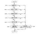
次に、本実施例の車両において、外部機器に電力を供給するときの処理について、図2に示すフローチャートを用いて説明する。図2に示す処理は、パワーマネージメントECU20によって実行される。
Next, processing when power is supplied to an external device in the vehicle of this embodiment will be described with reference to the flowchart shown in FIG. The process shown in FIG. 2 is executed by the power management ECU 20.
ステップS101において、パワーマネージメントECU20は、給電要求があるか否かを判別する。給電要求があるときには、ステップS102の処理に進む。給電要求がなければ、ステップS107の処理に進む。
In step S101, the power management ECU 20 determines whether or not there is a power supply request. When there is a power supply request, the process proceeds to step S102. If there is no power supply request, the process proceeds to step S107.
給電要求に関する情報は、パワーマネージメントECU20に入力される。例えば、給電を行うためのスイッチを車両に設けておき、スイッチが操作されたときに、スイッチの操作情報をパワーマネージメントECU20に入力することができる。パワーマネージメントECU20は、スイッチからの入力信号を受けて、給電要求があると判別することができる。
Information regarding the power supply request is input to the power management ECU 20. For example, a switch for supplying power can be provided in the vehicle, and switch operation information can be input to the power management ECU 20 when the switch is operated. The power management ECU 20 can determine that there is a power supply request in response to an input signal from the switch.
また、リモートキー24の操作によって、給電要求を行うことができる。リモートキー24の操作によって給電要求を行うときには、まず、リモートキー24および照合ECU23の間で、照合処理が行われる。照合処理が完了すると、照合ECU23は、リモートキー24の操作情報をパワーマネージメントECU20に送信する。リモートキー24の操作によって給電要求を行っているときには、給電要求に関する情報が、照合ECU23からパワーマネージメントECU20に送信される。パワーマネージメントECU20は、給電要求に関する情報を照合ECU23から受けることにより、給電要求があると判別することができる。
Also, a power supply request can be made by operating the remote key 24. When a power supply request is made by operating the remote key 24, first, verification processing is performed between the remote key 24 and the verification ECU 23. When the collation processing is completed, the collation ECU 23 transmits operation information of the remote key 24 to the power management ECU 20. When a power supply request is made by operating the remote key 24, information related to the power supply request is transmitted from the verification ECU 23 to the power management ECU 20. The power management ECU 20 can determine that there is a power supply request by receiving information on the power supply request from the verification ECU 23.
ステップS102において、パワーマネージメントECU20は、組電池14が正常状態であるか否かを判別する。組電池14の状態としては、例えば、SOC、電圧、温度がある。SOC、電圧および温度のうち、少なくとも1つの判別パラメータを用いて、組電池14が正常状態であるか否かの判別を行うことができる。組電池14が正常状態であるときには、ステップS103の処理に進む。組電池14が正常状態ではないときには、ステップS107の処理に進む。
In step S102, the power management ECU 20 determines whether or not the assembled battery 14 is in a normal state. Examples of the state of the assembled battery 14 include SOC, voltage, and temperature. It is possible to determine whether or not the assembled battery 14 is in a normal state using at least one determination parameter among the SOC, voltage, and temperature. When the assembled battery 14 is in a normal state, the process proceeds to step S103. When the assembled battery 14 is not in a normal state, the process proceeds to step S107.
組電池14のSOCが下限SOCよりも高く、上限SOCよりも低いとき、パワーマネージメントECU20は、組電池14が正常状態であると判別することができる。下限SOCおよび上限SOCは、組電池14の入出力特性などを考慮して、予め設定しておくことができる。設定されたSOCに関する情報は、メモリに記憶することができる。
When the SOC of the assembled battery 14 is higher than the lower limit SOC and lower than the upper limit SOC, the power management ECU 20 can determine that the assembled battery 14 is in a normal state. The lower limit SOC and the upper limit SOC can be set in advance in consideration of the input / output characteristics of the assembled battery 14 and the like. Information about the set SOC can be stored in a memory.
組電池14のSOCが下限SOCよりも低いときには、組電池14が過放電状態となるおそれがあるため、パワーマネージメントECU20は、組電池14が正常状態ではないと判別する。組電池14のSOCが上限SOCよりも高いときには、組電池14が過充電状態となるおそれがあるため、パワーマネージメントECU20は、組電池14が正常状態ではないと判別する。
When the SOC of the assembled battery 14 is lower than the lower limit SOC, the assembled battery 14 may be in an overdischarged state, so the power management ECU 20 determines that the assembled battery 14 is not in a normal state. When the SOC of the assembled battery 14 is higher than the upper limit SOC, the assembled battery 14 may be in an overcharged state, so the power management ECU 20 determines that the assembled battery 14 is not in a normal state.
組電池14のSOCは、組電池14のOCV(Open Circuit Voltage)から特定することができる。SOCおよびOCVは、対応関係にあるため、この対応関係を予め求めておけば、OCVからSOCを特定することができる。組電池14のOCVは、電圧センサを用いて検出された組電池14の電圧(CCV:Closed Circuit Voltage)から算出することができる。一方、電流センサを用いて、組電池14の充放電電流を検出し、組電池14を充放電したときの電流値を積算することにより、組電池14のSOCを算出することもできる。
The SOC of the assembled battery 14 can be specified from the OCV (Open Circuit Circuit) of the assembled battery 14. Since SOC and OCV are in a correspondence relationship, if this correspondence relationship is obtained in advance, the SOC can be specified from the OCV. The OCV of the assembled battery 14 can be calculated from the voltage (CCV: Closed Circuit Voltage) of the assembled battery 14 detected using a voltage sensor. On the other hand, the SOC of the assembled battery 14 can be calculated by detecting the charging / discharging current of the assembled battery 14 using a current sensor and integrating the current value when the assembled battery 14 is charged / discharged.
本実施例では、組電池14のSOCに基づいて、組電池14が正常状態であるか否かを判別しているが、これに限るものではない。組電池14を構成する単電池14aのSOCに基づいて、組電池14が正常状態であるか否かを判別することができる。例えば、単電池14aのSOCが下限SOCよりも高く、上限SOCよりも低いとき、パワーマネージメントECU20は、組電池14が正常状態であると判別することができる。単電池14aの下限SOCおよび上限SOCは、組電池14の下限SOCおよび上限SOCと同じであってもよいし、異なっていてもよい。
In this embodiment, whether or not the assembled battery 14 is in a normal state is determined based on the SOC of the assembled battery 14, but the present invention is not limited to this. Whether or not the assembled battery 14 is in a normal state can be determined based on the SOC of the unit cells 14a constituting the assembled battery 14. For example, when the SOC of the unit cell 14a is higher than the lower limit SOC and lower than the upper limit SOC, the power management ECU 20 can determine that the assembled battery 14 is in a normal state. The lower limit SOC and the upper limit SOC of the unit cell 14a may be the same as or different from the lower limit SOC and the upper limit SOC of the assembled battery 14.
組電池14の電圧が下限電圧よりも高く、上限電圧よりも低いとき、パワーマネージメントECU20は、組電池14が正常状態であると判別することができる。電圧センサを用いることにより、組電池14の電圧を検出することができ、電圧センサの検出情報は、パワーマネージメントECU20に入力される。下限電圧および上限電圧は、組電池14の入出力特性などを考慮して、予め設定しておくことができる。設定された電圧に関する情報は、メモリに記憶することができる。
When the voltage of the assembled battery 14 is higher than the lower limit voltage and lower than the upper limit voltage, the power management ECU 20 can determine that the assembled battery 14 is in a normal state. By using the voltage sensor, the voltage of the assembled battery 14 can be detected, and the detection information of the voltage sensor is input to the power management ECU 20. The lower limit voltage and the upper limit voltage can be set in advance in consideration of input / output characteristics of the assembled battery 14 and the like. Information about the set voltage can be stored in a memory.
組電池14の電圧が下限電圧よりも低いときには、組電池14が過放電状態となるおそれがあるため、パワーマネージメントECU20は、組電池14が正常状態ではないと判別する。組電池14の電圧が上限電圧よりも高いときには、組電池14が過充電状態となるおそれがあるため、パワーマネージメントECU20は、組電池14が正常状態ではないと判別する。
When the voltage of the assembled battery 14 is lower than the lower limit voltage, the assembled battery 14 may be in an overdischarged state, so the power management ECU 20 determines that the assembled battery 14 is not in a normal state. When the voltage of the assembled battery 14 is higher than the upper limit voltage, the assembled battery 14 may be in an overcharged state, so the power management ECU 20 determines that the assembled battery 14 is not in a normal state.
本実施例では、組電池14の電圧に基づいて、組電池14が正常状態であるか否かを判別しているが、これに限るものではない。組電池14を構成する単電池14aの電圧に基づいて、組電池14が正常状態であるか否かを判別することができる。例えば、各単電池14aの電圧が下限電圧よりも高く、上限電圧よりも低いとき、パワーマネージメントECU20は、組電池14が正常状態であると判別することができる。単電池14aの下限電圧および上限電圧は、組電池14の下限電圧および上限電圧とは異なる。
In this embodiment, whether or not the assembled battery 14 is in a normal state is determined based on the voltage of the assembled battery 14, but the present invention is not limited to this. Whether or not the assembled battery 14 is in a normal state can be determined based on the voltage of the unit cells 14a constituting the assembled battery 14. For example, when the voltage of each cell 14a is higher than the lower limit voltage and lower than the upper limit voltage, the power management ECU 20 can determine that the assembled battery 14 is in a normal state. The lower limit voltage and the upper limit voltage of the unit cell 14 a are different from the lower limit voltage and the upper limit voltage of the assembled battery 14.
組電池14の温度が下限温度よりも高く、上限温度よりも低いとき、パワーマネージメントECU20は、組電池14が正常状態であると判別する。温度センサを用いることにより、組電池14の温度を検出することができ、温度センサの検出情報は、パワーマネージメントECU20に入力される。下限温度および上限温度は、組電池14の入出力特性などを考慮して、予め設定しておくことができる。設定された温度に関する情報は、メモリに記憶することができる。
When the temperature of the assembled battery 14 is higher than the lower limit temperature and lower than the upper limit temperature, the power management ECU 20 determines that the assembled battery 14 is in a normal state. By using the temperature sensor, the temperature of the assembled battery 14 can be detected, and the temperature sensor detection information is input to the power management ECU 20. The lower limit temperature and the upper limit temperature can be set in advance in consideration of the input / output characteristics of the assembled battery 14 and the like. Information about the set temperature can be stored in a memory.
組電池14の温度が下限温度よりも低かったり、上限温度よりも高かったりするときには、組電池14の出力を確保することができないおそれがある。この場合には、パワーマネージメントECU20は、組電池14が正常状態ではないと判別する。
When the temperature of the assembled battery 14 is lower than the lower limit temperature or higher than the upper limit temperature, the output of the assembled battery 14 may not be ensured. In this case, the power management ECU 20 determines that the assembled battery 14 is not in a normal state.
ステップS103において、パワーマネージメントECU20は、発電機19が正常状態であるか否かを判別する。発電機19の状態としては、例えば、発電機19の温度がある。発電機19の温度が、予め定められた閾値よりも高いときには、発電機19の発電性能が低下してしまう。したがって、発電機19の温度が閾値よりも高いとき、パワーマネージメントECU20は、発電機19が正常状態ではないと判別する。
In step S103, the power management ECU 20 determines whether or not the generator 19 is in a normal state. The state of the generator 19 includes, for example, the temperature of the generator 19. When the temperature of the generator 19 is higher than a predetermined threshold, the power generation performance of the generator 19 is degraded. Therefore, when the temperature of the generator 19 is higher than the threshold, the power management ECU 20 determines that the generator 19 is not in a normal state.
発電機19の温度に関する閾値は、発電機19の発電性能などを考慮して適宜設定することができる。閾値に関する情報は、メモリに記憶することができる。温度センサを用いることにより、発電機19の温度を検出することができ、温度センサの検出情報は、パワーマネージメントECU20に入力される。
The threshold value related to the temperature of the generator 19 can be appropriately set in consideration of the power generation performance of the generator 19 and the like. Information about the threshold can be stored in a memory. By using the temperature sensor, the temperature of the generator 19 can be detected, and the detection information of the temperature sensor is input to the power management ECU 20.
ステップS104において、パワーマネージメントECU20は、車両が正常状態であるか否かを判別する。具体的には、パワーマネージメントECU20は、組電池14の電力を外部機器に供給するシステムや、発電機19が生成した電力を外部機器に供給するシステムが正常に動作するか否かを判別する。例えば、エンジン16や発電機19が故障しているとき、パワーマネージメントECU20は、車両が正常状態ではないと判別する。
In step S104, the power management ECU 20 determines whether or not the vehicle is in a normal state. Specifically, the power management ECU 20 determines whether or not a system that supplies power from the assembled battery 14 to an external device or a system that supplies power generated by the generator 19 to an external device operates normally. For example, when the engine 16 or the generator 19 is out of order, the power management ECU 20 determines that the vehicle is not in a normal state.
ステップS105において、パワーマネージメントECU20は、メータECU22から燃料の残量情報を取得する。燃料残量センサ18は、燃料タンク17に蓄えられた燃料の残量を検出し、検出結果をメータECU22に出力する。メータECU22は、燃料残量センサ18の検出結果をパワーマネージメントECU20に出力する。
In step S105, the power management ECU 20 acquires fuel remaining amount information from the meter ECU 22. The remaining fuel sensor 18 detects the remaining amount of fuel stored in the fuel tank 17 and outputs the detection result to the meter ECU 22. The meter ECU 22 outputs the detection result of the fuel remaining amount sensor 18 to the power management ECU 20.
パワーマネージメントECU20は、燃料の残量が閾値よりも多いか否かを判別する。燃料の残量に関する閾値は、予め設定しておくことができ、閾値に関する情報は、メモリに記憶することができる。燃料の残量が閾値よりも多いときには、ステップS106の処理に進む。燃料の残量が閾値よりも少ないときには、ステップS107の処理に進む。
The power management ECU 20 determines whether or not the remaining amount of fuel is greater than a threshold value. The threshold relating to the remaining amount of fuel can be set in advance, and information relating to the threshold can be stored in the memory. When the remaining amount of fuel is greater than the threshold value, the process proceeds to step S106. When the remaining amount of fuel is less than the threshold value, the process proceeds to step S107.
ステップS106において、パワーマネージメントECU20は、給電装置15を作動させることにより、外部機器への給電を開始させることができる。具体的には、パワーマネージメントECU20は、IGリレー11a,11bをオフからオンに切り替える。次に、パワーマネージメントECU20は、DC/DCコンバータ12を作動させるとともに、システムメインリレー13をオフからオンに切り替える。
In step S106, the power management ECU 20 can start power feeding to the external device by operating the power feeding device 15. Specifically, the power management ECU 20 switches the IG relays 11a and 11b from off to on. Next, the power management ECU 20 operates the DC / DC converter 12 and switches the system main relay 13 from OFF to ON.
システムメインリレー13をオフからオンに切り替えることにより、組電池14の電力を、給電装置15を介して外部機器に供給することができる。組電池14の放電によって組電池14の電圧(又はSOC)が低下したとき、パワーマネージメントECU20は、組電池14の放電を停止する。パワーマネージメントECU20は、電圧センサの出力に基づいて、組電池14の電圧やSOCを取得することができる。
By switching the system main relay 13 from OFF to ON, the electric power of the assembled battery 14 can be supplied to an external device via the power supply device 15. When the voltage (or SOC) of the assembled battery 14 decreases due to the discharge of the assembled battery 14, the power management ECU 20 stops discharging the assembled battery 14. The power management ECU 20 can acquire the voltage and SOC of the assembled battery 14 based on the output of the voltage sensor.
組電池14の放電が停止した後、エンジンECU21は、パワーマネージメントECU20からの制御情報を受けて、エンジン16を始動させる。エンジン16を始動することによって、エンジン16からの動力を受けた発電機19が電力を生成し、発電機19の電力が、給電装置15を介して外部機器に供給される。
After the discharge of the assembled battery 14 is stopped, the engine ECU 21 receives the control information from the power management ECU 20 and starts the engine 16. By starting the engine 16, the generator 19 that receives the power from the engine 16 generates electric power, and the electric power of the generator 19 is supplied to an external device via the power supply device 15.
ステップS106において、パワーマネージメントECU20は、音又は表示を用いて、給電が開始されることをユーザに通知する。
In step S106, the power management ECU 20 notifies the user that power feeding is started using a sound or a display.
具体的には、パワーマネージメントECU20は、メータECU22又は照合ECU23に、給電が開始されることを示す情報を送信する。メータECU22は、パワーマネージメントECU20から送信された情報を受けて、車両に搭載されたディスプレイに給電の開始情報を表示させたり、車両に搭載されたスピーカから給電の開始情報(音声)を出力させたりすることができる。
Specifically, the power management ECU 20 transmits information indicating that power feeding is started to the meter ECU 22 or the verification ECU 23. The meter ECU 22 receives the information transmitted from the power management ECU 20 and displays power supply start information on a display mounted on the vehicle, or outputs power supply start information (voice) from a speaker mounted on the vehicle. can do.
リモートキー24がディスプレイ又はスピーカを備えているとき、照合ECU23は、給電の開始情報をリモートキー24に送信する。リモートキー24は、照合ECU23からの情報を受けて、ディスプレイに給電の開始情報を表示させたり、スピーカから給電の開始情報(音声)を出力させたりすることができる。
When the remote key 24 includes a display or a speaker, the verification ECU 23 transmits power supply start information to the remote key 24. The remote key 24 can receive information from the verification ECU 23 and display power supply start information on a display or output power supply start information (voice) from a speaker.
車両又はリモートキー24のディスプレイに給電の開始情報を表示させるとき、ディスプレイの表示内容は、給電の開始をユーザが認識できる内容であればよい。また、車両又はリモートキー24のスピーカから、給電の開始情報を音声として出力するとき、音声情報は、給電の開始をユーザが認識できるものであればよい。
When displaying start information of power supply on the display of the vehicle or the remote key 24, the display content of the display may be content that allows the user to recognize the start of power supply. Further, when the power supply start information is output as sound from the vehicle or the speaker of the remote key 24, the sound information may be any information that allows the user to recognize the start of power supply.
ステップS107において、パワーマネージメントECU20は、給電装置15の作動を停止させる。給電装置15から外部機器に電力が供給されているときには、外部機器への電力供給が停止される。
In step S107, the power management ECU 20 stops the operation of the power feeding device 15. When power is supplied from the power supply device 15 to the external device, the power supply to the external device is stopped.
また、ステップS107において、パワーマネージメントECU20は、音又は表示を用いて、給電が行われないことをユーザに通知する。具体的には、パワーマネージメントECU20は、メータECU22又は照合ECU23に、給電が行われないことを示す情報を送信する。メータECU22は、パワーマネージメントECU20から送信された情報を受けて、車両に搭載されたディスプレイに給電の停止情報を表示させたり、車両に搭載されたスピーカから給電の停止情報(音声)を出力させたりすることができる。
In step S107, the power management ECU 20 notifies the user that power feeding is not performed using sound or display. Specifically, power management ECU20 transmits the information which shows that electric power feeding is not performed to meter ECU22 or collation ECU23. The meter ECU 22 receives the information transmitted from the power management ECU 20 and displays power supply stop information on a display mounted on the vehicle, or outputs power supply stop information (voice) from a speaker mounted on the vehicle. can do.
リモートキー24がディスプレイ又はスピーカを備えているとき、照合ECU23は、給電の停止情報をリモートキー24に送信する。リモートキー24は、照合ECU23からの情報を受けて、ディスプレイに給電の停止情報を表示させたり、スピーカから給電の停止情報(音声)を出力させたりすることができる。
When the remote key 24 includes a display or a speaker, the verification ECU 23 transmits power supply stop information to the remote key 24. The remote key 24 can receive information from the verification ECU 23 and can display power supply stop information on a display or output power supply stop information (voice) from a speaker.
給電の開始情報又は停止情報をリモートキー24に送信することにより、車両から離れた位置において外部機器を使用しているときに、ユーザは、リモートキー24を用いて給電情報を確認することができる。
By transmitting the power feeding start information or stop information to the remote key 24, the user can check the power feeding information using the remote key 24 when using an external device at a position away from the vehicle. .
車両又はリモートキー24のディスプレイに給電の停止情報を表示させるとき、ディスプレイの表示内容は、給電が行われないことをユーザが認識できる内容であればよい。また、車両又はリモートキー24のスピーカから、給電の停止情報を音声として出力するとき、音声情報は、給電が行われないことをユーザが認識できるものであればよい。
When displaying power supply stop information on the display of the vehicle or the remote key 24, the display content of the display may be content that allows the user to recognize that power supply is not performed. Further, when the power supply stop information is output as sound from the vehicle or the speaker of the remote key 24, the sound information may be anything that allows the user to recognize that power supply is not performed.
一方、パワーマネージメントECU20は、車両に搭載されたライトを駆動することにより、給電が行われないことをユーザに通知することができる。例えば、所定の点滅パターンでライトを駆動することにより、給電が行われないことをユーザに通知することができる。ライトは、車両に搭載されているものであればよく、ライトとしては、例えば、ヘッドライト、テールライト、室内灯がある。
On the other hand, the power management ECU 20 can notify the user that power feeding is not performed by driving a light mounted on the vehicle. For example, the user can be notified that power is not supplied by driving the light with a predetermined blinking pattern. The light may be any light mounted on the vehicle, and examples of the light include a headlight, a taillight, and an interior light.
車両又はリモートキー24のディスプレイには、給電が行われない理由に関する情報を表示させることができる。ステップS101~ステップS105の処理からステップS107の処理に進んだときには、ステップS101~ステップS105の処理で判別された内容を、給電が行われない理由とすることができる。
Information on the reason why power is not supplied can be displayed on the display of the vehicle or the remote key 24. When the process proceeds from step S101 to step S105 to step S107, the content determined by the process from step S101 to step S105 can be regarded as the reason why power is not supplied.
ステップS101の処理において、給電要求が無いときには、給電が行われない理由として、給電要求を受けていないことを示す情報をディスプレイに表示させることができる。ディスプレイの表示内容は、給電要求を受けていないことをユーザが認識できる内容であればよい。
In the process of step S101, when there is no power supply request, information indicating that the power supply request is not received can be displayed on the display as the reason why power supply is not performed. The display content of the display may be content that allows the user to recognize that no power supply request has been received.
車両に搭載されたスイッチの操作によって給電要求を行うときに、スイッチの誤操作によって、給電要求が正しく行われないことがある。また、リモートキー24の操作によって給電要求を行うときに、リモートキー24の誤操作によって、給電要求が正しく行われないことがある。この場合には、ユーザは、ディスプレイの表示内容を見ることにより、給電要求が行われていないことを確認することができる。そして、ユーザは、スイッチ又はリモートキー24を操作することにより、再び給電要求を行うことができる。
When a power supply request is made by operating a switch mounted on the vehicle, the power supply request may not be made correctly due to an erroneous switch operation. Further, when a power supply request is made by operating the remote key 24, the power supply request may not be made correctly due to an erroneous operation of the remote key 24. In this case, the user can confirm that the power supply request is not made by looking at the display content of the display. Then, the user can request power supply again by operating the switch or the remote key 24.
ステップS102の処理において、組電池14が正常状態ではないときには、給電が行われない理由として、組電池14が正常状態ではないことを示す情報をディスプレイに表示させることができる。ディスプレイの表示内容は、組電池14が正常状態ではないことをユーザが認識できる内容であればよい。ユーザは、ディスプレイの表示内容を見ることにより、組電池14が正常状態ではないことを確認することができる。そして、ユーザは、組電池14の点検が必要であることを認識することができる。
In the process of step S102, when the assembled battery 14 is not in a normal state, information indicating that the assembled battery 14 is not in a normal state can be displayed on the display as a reason why power feeding is not performed. The display content of the display may be content that allows the user to recognize that the assembled battery 14 is not in a normal state. The user can confirm that the assembled battery 14 is not in a normal state by looking at the display content of the display. Then, the user can recognize that the assembled battery 14 needs to be checked.
ステップS103の処理において、発電機19が正常状態ではないときには、給電が行われない理由として、発電機19が正常状態ではないことを示す情報をディスプレイに表示させることができる。ディスプレイの表示内容は、発電機19が正常状態ではないことをユーザが認識できる内容であればよい。ユーザは、ディスプレイの表示内容を見ることにより、発電機19が正常状態ではないことを確認することができる。そして、ユーザは、発電機19の点検が必要であることを認識することができる。
In the process of step S103, when the generator 19 is not in a normal state, information indicating that the generator 19 is not in a normal state can be displayed on the display as a reason why power feeding is not performed. The display content of the display may be content that allows the user to recognize that the generator 19 is not in a normal state. The user can confirm that the generator 19 is not in a normal state by looking at the display content of the display. Then, the user can recognize that the generator 19 needs to be checked.
ステップS104の処理において、車両が正常状態ではないときには、給電が行われない理由として、車両が正常状態ではないことを示す情報をディスプレイに表示させることができる。ディスプレイの表示内容は、車両が正常状態ではないことをユーザが認識できる内容であればよい。ユーザは、ディスプレイの表示内容を見ることにより、車両が正常状態ではないことを確認することができる。そして、ユーザは、車両の点検が必要であることを認識することができる。
In the process of step S104, when the vehicle is not in a normal state, information indicating that the vehicle is not in a normal state can be displayed on the display as a reason why power is not supplied. The display content of the display may be content that allows the user to recognize that the vehicle is not in a normal state. The user can confirm that the vehicle is not in a normal state by viewing the display content on the display. The user can recognize that the vehicle needs to be inspected.
ステップS105の処理において、燃料の残量が閾値よりも少ないときには、給電が行われない理由として、燃料タンク17に蓄えられた燃料が不足していることを示す情報をディスプレイに表示させることができる。ディスプレイの表示内容は、燃料が不足していることをユーザが認識できる内容であればよい。ユーザは、ディスプレイの表示内容を見ることにより、燃料が不足していることを確認することができる。そして、ユーザは、燃料を補充する必要があることを認識することができる。
In the process of step S105, when the remaining amount of fuel is less than the threshold value, information indicating that the fuel stored in the fuel tank 17 is insufficient can be displayed on the display as the reason why power supply is not performed. . The display content of the display may be content that allows the user to recognize that the fuel is insufficient. The user can confirm that the fuel is insufficient by looking at the display content of the display. Then, the user can recognize that the fuel needs to be replenished.
一方、給電が行われない理由に関する情報を、音声としてスピーカから出力することができる。ステップS101~ステップS105の処理からステップS107の処理に進んだときには、ステップS101~ステップS105の処理で判別された内容を、給電が行われない理由とすることができる。
On the other hand, information on the reason why power is not supplied can be output as audio from the speaker. When the process proceeds from step S101 to step S105 to step S107, the content determined by the process from step S101 to step S105 can be regarded as the reason why power is not supplied.
具体的には、上述したディスプレイに表示される情報を、音声としてスピーカから出力することができる。スピーカから出力される音声は、ステップS101~ステップS105の処理で判別された内容が分かるものであればよい。例えば、ステップS105の処理において、燃料の残量が閾値よりも少ないときには、給電が行われない理由として、燃料タンク17に蓄えられた燃料が不足していることを示す情報を、音声として出力することができる。
Specifically, the information displayed on the above-described display can be output as a sound from a speaker. The sound output from the speaker may be anything that can understand the contents determined in the processing of steps S101 to S105. For example, in the process of step S105, when the remaining amount of fuel is less than the threshold value, information indicating that the fuel stored in the fuel tank 17 is insufficient is output as a sound as the reason why power supply is not performed. be able to.
本実施例によれば、外部機器への給電を停止したとき、ユーザは、給電が停止されたことを確認できるだけでなく、給電が停止された理由も確認することができる。ユーザは、給電が停止された理由に基づいて、給電が停止された後の処置を決めることができる。
According to the present embodiment, when the power supply to the external device is stopped, the user can not only confirm that the power supply is stopped, but can also check the reason why the power supply is stopped. The user can decide the treatment after the power supply is stopped based on the reason that the power supply is stopped.
本実施例では、ステップS105~ステップS107の処理を行っているが、これに限るものではない。ステップS105~ステップS107の処理のうち、少なくとも1つの処理を行うことができればよい。
In the present embodiment, the processing from step S105 to step S107 is performed, but the present invention is not limited to this. It is sufficient that at least one of the processes in steps S105 to S107 can be performed.
本実施例では、給電装置15から外部機器への給電を停止させているが、これに限るものではない。例えば、ステップS107の処理において、図1に示すシステムの作動を停止させることができる。システムの作動を停止させることにより、システムメインリレー13は、オンからオフに切り替えられる。
In this embodiment, power supply from the power supply device 15 to the external device is stopped, but the present invention is not limited to this. For example, in the process of step S107, the operation of the system shown in FIG. 1 can be stopped. By stopping the operation of the system, the system main relay 13 is switched from on to off.
本実施例では、車両を走行させる動力源として、組電池14およびエンジン16を備えた車両(いわゆるハイブリッド自動車)について説明したが、これに限るものではない。
In the present embodiment, a vehicle (so-called hybrid vehicle) provided with the assembled battery 14 and the engine 16 has been described as a power source for running the vehicle. However, the present invention is not limited to this.
例えば、車両の動力源として、組電池14だけを備えた車両(いわゆる電気自動車)に対しても、本発明を適用することができる。電気自動車では、図1に示すエンジン16および発電機19が省略され、組電池14の電力が、給電装置15を介して外部機器に供給される。また、車両の動力源として、エンジン16だけを備えた車両についても、本発明を適用することができる。この場合には、図1に示す組電池14が省略され、発電機19の電力が、給電装置15を介して外部機器に供給される。
For example, the present invention can be applied to a vehicle (so-called electric vehicle) having only the assembled battery 14 as a power source of the vehicle. In the electric vehicle, the engine 16 and the generator 19 shown in FIG. 1 are omitted, and the electric power of the assembled battery 14 is supplied to an external device via the power supply device 15. Further, the present invention can be applied to a vehicle including only the engine 16 as a power source of the vehicle. In this case, the assembled battery 14 shown in FIG. 1 is omitted, and the power of the generator 19 is supplied to the external device via the power feeding device 15.
外部電源の電力を組電池14に供給する充電システムを、車両に搭載することができる。外部電源は、車両の外部において、車両とは別に設けられた電源であり、外部電源としては、例えば、商用電源を用いることができる。外部電源が交流電力を供給するときには、車両に搭載された充電器によって、交流電力を直流電力に変換することができる。そして、充電器は、直流電力を組電池14に供給することができる。外部電源が直流電力を供給するときには、直流電力を組電池14に供給することができる。
A charging system that supplies power from the external power source to the assembled battery 14 can be mounted on the vehicle. The external power source is a power source provided separately from the vehicle outside the vehicle. For example, a commercial power source can be used as the external power source. When the external power supply supplies AC power, the AC power can be converted to DC power by a charger mounted on the vehicle. The charger can supply DC power to the assembled battery 14. When the external power supply supplies DC power, DC power can be supplied to the assembled battery 14.