JP2014201245A - Hybrid vehicle - Google Patents
Hybrid vehicle Download PDFInfo
- Publication number
- JP2014201245A JP2014201245A JP2013080329A JP2013080329A JP2014201245A JP 2014201245 A JP2014201245 A JP 2014201245A JP 2013080329 A JP2013080329 A JP 2013080329A JP 2013080329 A JP2013080329 A JP 2013080329A JP 2014201245 A JP2014201245 A JP 2014201245A
- Authority
- JP
- Japan
- Prior art keywords
- power
- battery
- engine
- target
- charging
- Prior art date
- Legal status (The legal status is an assumption and is not a legal conclusion. Google has not performed a legal analysis and makes no representation as to the accuracy of the status listed.)
- Pending
Links
Images


Classifications
-
- B—PERFORMING OPERATIONS; TRANSPORTING
- B60—VEHICLES IN GENERAL
- B60W—CONJOINT CONTROL OF VEHICLE SUB-UNITS OF DIFFERENT TYPE OR DIFFERENT FUNCTION; CONTROL SYSTEMS SPECIALLY ADAPTED FOR HYBRID VEHICLES; ROAD VEHICLE DRIVE CONTROL SYSTEMS FOR PURPOSES NOT RELATED TO THE CONTROL OF A PARTICULAR SUB-UNIT
- B60W10/00—Conjoint control of vehicle sub-units of different type or different function
- B60W10/24—Conjoint control of vehicle sub-units of different type or different function including control of energy storage means
- B60W10/26—Conjoint control of vehicle sub-units of different type or different function including control of energy storage means for electrical energy, e.g. batteries or capacitors
-
- B—PERFORMING OPERATIONS; TRANSPORTING
- B60—VEHICLES IN GENERAL
- B60W—CONJOINT CONTROL OF VEHICLE SUB-UNITS OF DIFFERENT TYPE OR DIFFERENT FUNCTION; CONTROL SYSTEMS SPECIALLY ADAPTED FOR HYBRID VEHICLES; ROAD VEHICLE DRIVE CONTROL SYSTEMS FOR PURPOSES NOT RELATED TO THE CONTROL OF A PARTICULAR SUB-UNIT
- B60W10/00—Conjoint control of vehicle sub-units of different type or different function
- B60W10/04—Conjoint control of vehicle sub-units of different type or different function including control of propulsion units
- B60W10/06—Conjoint control of vehicle sub-units of different type or different function including control of propulsion units including control of combustion engines
-
- B—PERFORMING OPERATIONS; TRANSPORTING
- B60—VEHICLES IN GENERAL
- B60W—CONJOINT CONTROL OF VEHICLE SUB-UNITS OF DIFFERENT TYPE OR DIFFERENT FUNCTION; CONTROL SYSTEMS SPECIALLY ADAPTED FOR HYBRID VEHICLES; ROAD VEHICLE DRIVE CONTROL SYSTEMS FOR PURPOSES NOT RELATED TO THE CONTROL OF A PARTICULAR SUB-UNIT
- B60W10/00—Conjoint control of vehicle sub-units of different type or different function
- B60W10/04—Conjoint control of vehicle sub-units of different type or different function including control of propulsion units
- B60W10/08—Conjoint control of vehicle sub-units of different type or different function including control of propulsion units including control of electric propulsion units, e.g. motors or generators
-
- B—PERFORMING OPERATIONS; TRANSPORTING
- B60—VEHICLES IN GENERAL
- B60W—CONJOINT CONTROL OF VEHICLE SUB-UNITS OF DIFFERENT TYPE OR DIFFERENT FUNCTION; CONTROL SYSTEMS SPECIALLY ADAPTED FOR HYBRID VEHICLES; ROAD VEHICLE DRIVE CONTROL SYSTEMS FOR PURPOSES NOT RELATED TO THE CONTROL OF A PARTICULAR SUB-UNIT
- B60W20/00—Control systems specially adapted for hybrid vehicles
- B60W20/10—Controlling the power contribution of each of the prime movers to meet required power demand
- B60W20/13—Controlling the power contribution of each of the prime movers to meet required power demand in order to stay within battery power input or output limits; in order to prevent overcharging or battery depletion
-
- B—PERFORMING OPERATIONS; TRANSPORTING
- B60—VEHICLES IN GENERAL
- B60W—CONJOINT CONTROL OF VEHICLE SUB-UNITS OF DIFFERENT TYPE OR DIFFERENT FUNCTION; CONTROL SYSTEMS SPECIALLY ADAPTED FOR HYBRID VEHICLES; ROAD VEHICLE DRIVE CONTROL SYSTEMS FOR PURPOSES NOT RELATED TO THE CONTROL OF A PARTICULAR SUB-UNIT
- B60W50/00—Details of control systems for road vehicle drive control not related to the control of a particular sub-unit, e.g. process diagnostic or vehicle driver interfaces
- B60W50/08—Interaction between the driver and the control system
- B60W50/085—Changing the parameters of the control units, e.g. changing limit values, working points by control input
-
- B—PERFORMING OPERATIONS; TRANSPORTING
- B60—VEHICLES IN GENERAL
- B60W—CONJOINT CONTROL OF VEHICLE SUB-UNITS OF DIFFERENT TYPE OR DIFFERENT FUNCTION; CONTROL SYSTEMS SPECIALLY ADAPTED FOR HYBRID VEHICLES; ROAD VEHICLE DRIVE CONTROL SYSTEMS FOR PURPOSES NOT RELATED TO THE CONTROL OF A PARTICULAR SUB-UNIT
- B60W2710/00—Output or target parameters relating to a particular sub-units
- B60W2710/24—Energy storage means
- B60W2710/242—Energy storage means for electrical energy
- B60W2710/244—Charge state
-
- Y—GENERAL TAGGING OF NEW TECHNOLOGICAL DEVELOPMENTS; GENERAL TAGGING OF CROSS-SECTIONAL TECHNOLOGIES SPANNING OVER SEVERAL SECTIONS OF THE IPC; TECHNICAL SUBJECTS COVERED BY FORMER USPC CROSS-REFERENCE ART COLLECTIONS [XRACs] AND DIGESTS
- Y02—TECHNOLOGIES OR APPLICATIONS FOR MITIGATION OR ADAPTATION AGAINST CLIMATE CHANGE
- Y02T—CLIMATE CHANGE MITIGATION TECHNOLOGIES RELATED TO TRANSPORTATION
- Y02T10/00—Road transport of goods or passengers
- Y02T10/60—Other road transportation technologies with climate change mitigation effect
- Y02T10/62—Hybrid vehicles
Abstract
Description
本発明は、ハイブリッド車両に関し、詳しくは、エンジンと、前記エンジンからの動力を用いて発電するモータと、モータと電力をやりとりするバッテリと、を備える。 The present invention relates to a hybrid vehicle, and more specifically, includes an engine, a motor that generates electric power using power from the engine, and a battery that exchanges electric power with the motor.
従来、この種のハイブリッド車両としては、エンジンと、エンジンを動力源として発電を行なう第1のモータジェネレータと、車両駆動を行なう第2のモータジェネレータと、第1のモータジェネレータにより発電された電気を充電すると共に第2のモータジェネレータへ電気を供給するバッテリとを備える第1のモータジェネレータが発電した電気でバッテリを充電する際に、充電開始後、パドルシフトの「+」レバーが押されたときに発電時間を加算し、「−」レバーが押されたときに発電時間を減算し、こうして加減した発電時間でバッテリの充電を行なうものが提案されている(例えば、特許文献1参照)。この車両では、こうした制御により、所望の時間内にバッテリを充電できるとしている。 Conventionally, this type of hybrid vehicle includes an engine, a first motor generator that generates electric power using the engine as a power source, a second motor generator that drives the vehicle, and electricity generated by the first motor generator. When the battery is charged with electricity generated by the first motor generator, the battery being charged and supplying electricity to the second motor generator, after the start of charging, the "+" lever of the paddle shift is pushed There has been proposed a method in which the power generation time is added to the battery, the power generation time is subtracted when the “−” lever is pressed, and the battery is charged with the power generation time thus adjusted (see Patent Document 1, for example). In this vehicle, the battery can be charged within a desired time by such control.
ところで、走行用の動力を出力するエンジンと、走行用の動力を入出力可能なモータと、モータと電力をやりとりするバッテリとを備えるハイブリッド車両では、例えば、目的地が排ガスを一切排出しない自動車のみに走行が許可される地域である場合など、エンジンを運転せずにモータからの動力のみで走行するモータ走行に備えて、ユーザが目的地でバッテリの蓄電量が目標蓄電量まで充電されることを望む場合がある。こうしたユーザの要求に対応する手法として、ユーザによりバッテリの充電要求がなされたときには、バッテリの蓄電量が目標蓄電量となるようエンジンやモータを制御する手法が考えられるが、この手法では、バッテリの蓄電量の増加速度が遅いと蓄電量が目標蓄電量に達する前に目的地に到達してしまう場合がある。 By the way, in a hybrid vehicle including an engine that outputs driving power, a motor that can input and output driving power, and a battery that exchanges power with the motor, for example, only a vehicle whose destination does not emit any exhaust gas. For example, when the vehicle is in a region where travel is permitted, the user is charged with the amount of charge stored in the battery to the target amount of charge at the destination in preparation for motor travel that travels using only power from the motor without operating the engine. May want. As a method for responding to such a user request, when a battery charging request is made by the user, a method of controlling the engine and the motor so that the stored amount of the battery becomes the target stored amount can be considered. If the increase rate of the charged amount is slow, the charged amount may reach the destination before reaching the target charged amount.
本発明のハイブリッド車両は、バッテリの充電の促進が指示されたときに、ユーザの所望する増加速度でバッテリの蓄電量を増加させることを主目的とする。 The main purpose of the hybrid vehicle of the present invention is to increase the amount of electricity stored in the battery at an increase rate desired by the user when an instruction to promote battery charging is given.
本発明のハイブリッド車両は、上述の主目的を達成するために以下の手段を採った。 The hybrid vehicle of the present invention employs the following means in order to achieve the main object described above.
本発明のハイブリッド車両では、
エンジンと、前記エンジンからの動力を用いて発電するモータと、前記モータと電力をやりとりするバッテリと、を備えるハイブリッド車両であって、
前記バッテリの充電の促進が指示されたときに前記バッテリの蓄電量の増加速度が指示されたときには、前記指示された増加速度で前記バッテリの蓄電量が増加するよう前記エンジンと前記モータとを制御する制御手段
を備えることを要旨とする。
In the hybrid vehicle of the present invention,
A hybrid vehicle comprising an engine, a motor that generates electric power using power from the engine, and a battery that exchanges electric power with the motor,
When an instruction to increase the amount of charge of the battery is instructed when promotion of charging of the battery is instructed, the engine and the motor are controlled so that the amount of charge of the battery increases at the instructed increase speed. The gist is to provide control means for
この本発明のハイブリッド車両では、バッテリの充電の促進が指示されたときにバッテリの蓄電量の増加速度が指示されたときには、指示された増加速度でバッテリの蓄電量が増加するようエンジンとモータとを制御する。これにより、バッテリの充電の促進が指示されたときに、ユーザの所望する増加速度でバッテリの蓄電量を増加させることができる。 In the hybrid vehicle of the present invention, when an instruction for increasing the battery charge is instructed when the battery charge is instructed, the engine and the motor are arranged so that the battery charge increases at the instructed increase speed. To control. Thereby, when promotion of charge of the battery is instructed, the amount of charge of the battery can be increased at an increase rate desired by the user.
こうした本発明のハイブリッド車両において、前記バッテリの蓄電量の増加速度は、目標蓄電量に至るまでの充電所要時間が指示されることで指示され、前記増加速度は、前記充電の促進が指示されてから前記充電所要時間を経過したとき以降に前記蓄電量が前記目標蓄電量になる速度であるものとすることもできる。こうすれば、ユーザの所望するタイミングにより近いタイミングでバッテリの蓄電量を目標蓄電量とすることもできる。この場合において、前記モータは、前記エンジンからの動力で発電し、前記制御手段は、前記バッテリの充電の促進が指示されたときには、前記蓄電量を前記目標蓄電量にするために前記バッテリの充電に要求される充電要求パワーを前記バッテリの充電に許容される電力の上限値である上限充電パワーで制限したパワーと、前記走行要求パワーと、の和のパワーが前記エンジンから出力されるよう前記エンジンを制御する手段であるものとすることもできる。こうすれば、エンジンからのパワーを用いてバッテリを充電して、バッテリの蓄電量を目標蓄電量にすることができる。 In such a hybrid vehicle of the present invention, the rate of increase in the amount of charge of the battery is instructed by instructing the time required for charging to reach the target amount of charge, and the rate of increase is instructed to promote the charge. From the time when the required charging time elapses, the power storage amount may be a speed at which the target power storage amount is reached. If it carries out like this, the electrical storage amount of a battery can also be made into the target electrical storage amount at timing close | similar to the timing which a user desires. In this case, the motor generates power with power from the engine, and when the control unit is instructed to promote charging of the battery, charging of the battery is performed in order to set the charged amount to the target charged amount. The power required for charging is limited by the upper limit charging power, which is the upper limit value of the power allowed for charging the battery, and the sum of the required driving power is output from the engine. It can also be a means for controlling the engine. If it carries out like this, a battery can be charged using the power from an engine, and the electrical storage amount of a battery can be made into the target electrical storage amount.
ユーザによりバッテリの目標蓄電量と充電所要時間とが指示される態様の本発明のハイブリッド車両において、情報を報知する報知手段を備え、前記制御手段は、前記バッテリの充電の促進が指示されたときには、前記充電の促進の指示がなされてから前記蓄電量が前記目標蓄電量に至るまでの所要時間の推定値である推定所要時間が前記報知手段で報知されるよう前記報知手段を制御する手段であるものとすることもできる。こうすれば、ユーザが指示した充電所要時間で蓄電量が目標蓄電量に達しない場合にユーザが違和感を覚えることを抑制することができる。 In the hybrid vehicle of the present invention in which the target battery charge amount and the required charging time are instructed by the user, the hybrid vehicle according to the present invention includes an informing means for informing information, and the control means is instructed to promote charging of the battery. Means for controlling the notification means so that the notification means notifies the estimated required time, which is an estimated value of the required time from when the charge promotion instruction is given until the storage amount reaches the target storage amount. It can also be. By so doing, it is possible to suppress the user from feeling uncomfortable when the amount of stored electricity does not reach the target amount of stored charge during the required charging time indicated by the user.
報知手段を備える態様の本発明のハイブリッド車両において、前記制御手段は、前記バッテリの蓄電量が前記目標蓄電量に至るまでの前記走行要求パワーの推定値である推定走行パワーと、前記バッテリの蓄電量が前記目標蓄電量に至るまでの前記バッテリを充電するパワーの平均値である平均充電パワーを前記上限充電パワーで制限したものと、前記入力された充電所要時間と、を用いて前記推定所要時間を演算する手段であるものとすることもできる。この場合において、前記推定走行パワーは、前記バッテリの充電の促進が指示される前にイグニッションオンされてからイグニションオフされるまでの期間における前記走行要求パワーの平均値であるものとすることもできる。 In the hybrid vehicle according to the aspect of the invention including the notifying unit, the control unit includes an estimated traveling power that is an estimated value of the required traveling power until the storage amount of the battery reaches the target storage amount, and the storage of the battery. The estimated required value using an average charge power that is an average value of the power for charging the battery until the amount reaches the target power storage amount with the upper limit charge power and the input required charge time It can also be a means for calculating time. In this case, the estimated traveling power may be an average value of the traveling required power in a period from when the ignition is turned on before the battery charging is instructed until the ignition is turned off. .
報知手段を備える態様の本発明のハイブリッド車両において、前記報知手段は、前記情報を視認可能に表示する手段であるものとすることもできる。 In the hybrid vehicle according to the aspect of the invention including the notification unit, the notification unit may be a unit that displays the information in a visually recognizable manner.
また、本発明のハイブリッド車両において、外部の機器が接続されたときに前記バッテリから前記外部の機器に電力を供給可能な外部電力供給装置を備えるものとすることもできる。 The hybrid vehicle of the present invention may further include an external power supply device that can supply power from the battery to the external device when an external device is connected.
次に、本発明を実施するための形態を実施例を用いて説明する。 Next, the form for implementing this invention is demonstrated using an Example.
図1は、本発明の第1実施例としてのハイブリッド自動車20の構成の概略を示す構成図である。第1実施例のハイブリッド自動車20は、図1に示すように、ガソリンや軽油などを燃料として動力を出力するエンジン22と、エンジン22を駆動制御するエンジン用電子制御ユニット(以下、エンジンECUという)24と、エンジン22のクランクシャフト26にキャリアが接続されると共に駆動輪38a,38bにデファレンシャルギヤ37を介して連結された駆動軸36にリングギヤが接続されたシングルピニオン式のプラネタリギヤ30と、例えば同期発電電動機として構成されて回転子がプラネタリギヤ30のサンギヤに接続されたモータMG1と、例えば同期発電電動機として構成されて回転子が駆動軸36に接続されたモータMG2と、モータMG1,MG2を駆動するためのインバータ41,42と、インバータ41,42の図示しないスイッチング素子をスイッチング制御することによってモータMG1,MG2を駆動制御するモータ用電子制御ユニット(以下、モータECUという)40と、例えばリチウムイオン二次電池として構成されてインバータ41,42を介してモータMG1,MG2と電力をやりとりする高電圧バッテリ50と、高電圧バッテリ50を管理するバッテリ用電子制御ユニット(以下、バッテリECUという)52と、家庭用電源などの外部電源に接続されて高電圧バッテリ50を充電可能な充電器60と、車両の構成要素でない外部機器(例えば、家庭用電化製品など)のプラグを差込可能なコンセント94と、コンセント94に外部機器のプラグが差し込まれているときにインバータ41,42や高電圧バッテリ50が接続された電力ライン54の直流電力を所定電圧(例えば100Vなど)の交流電力に変換してコンセント94(外部機器)に供給可能なDC/AC変換器96と、入力された画像情報を表示すると共にユーザが画面に表示された画像を手で触れたり専用のペンで触れると触れられた画面位置を感知して情報信号を出力するタッチパネル98と、車両全体を制御するハイブリッド用電子制御ユニット(以下、HVECUという)70と、を備える。なお、コンセント94とDC/AC変換器96とが本発明の「外部電力供給装置」に相当する。
FIG. 1 is a configuration diagram showing an outline of the configuration of a
エンジンECU24は、図示しないが、CPUを中心とするマイクロプロセッサとして構成されており、CPUの他に、処理プログラムを記憶するROMやデータを一時的に記憶するRAM,入出力ポート,通信ポートを備える。エンジンECU24には、エンジン22の状態を検出する種々のセンサからの信号、例えば、クランクシャフト26の回転位置を検出するクランクポジションセンサからのクランクポジションやエンジン22の冷却水の温度を検出する水温センサからの冷却水温Tw,スロットルバルブのポジションを検出するスロットルバルブポジションセンサからのスロットルポジション,吸気管に取り付けられたエアフローメータからの吸入空気量Qaなどの信号が入力ポートを介して入力されている。また、エンジンECU24からは、エンジン22を駆動するための種々の制御信号、例えば、燃料噴射弁への駆動信号や、スロットルバルブのポジションを調節するスロットルモータへの駆動信号、イグニッションコイルへの制御信号などが出力ポートを介して出力されている。エンジンECU24は、HVECU70と通信しており、HVECU70からの制御信号によりエンジン22を運転制御すると共に必要に応じてエンジン22の運転状態に関するデータを出力する。なお、エンジンECU24は、クランクポジションセンサからのクランクポジションに基づいてクランクシャフト26の回転数、即ちエンジン22の回転数Neも演算している。
Although not shown, the engine ECU 24 is configured as a microprocessor centered on a CPU, and includes a ROM for storing a processing program, a RAM for temporarily storing data, an input / output port, and a communication port in addition to the CPU. . The engine ECU 24 includes signals from various sensors that detect the state of the
モータECU40は、図示しないが、CPUを中心とするマイクロプロセッサとして構成されており、CPUの他に、処理プログラムを記憶するROMやデータを一時的に記憶するRAM,入出力ポート,通信ポートを備える。モータECU40には、モータMG1,MG2を駆動制御するために必要な信号、例えばモータMG1,MG2の回転子の回転位置を検出する回転位置検出センサ43,44からの回転位置θm1,θm2や図示しない電流センサにより検出されるモータMG1,MG2に印加される相電流などが入力ポートを介して入力されており、モータECU40からは、インバータ41,42の図示しないスイッチング素子へのスイッチング制御信号などが出力ポートを介して出力されている。また、モータECU40は、HVECU70と通信しており、HVECU70からの制御信号によってモータMG1,MG2を駆動制御すると共に必要に応じてモータMG1,MG2の運転状態に関するデータをHVECU70に出力する。なお、モータECU40は、回転位置検出センサ43,44からのモータMG1,MG2の回転子の回転位置θm1,θm2に基づいてモータMG1,MG2の回転角速度ωm1,ωm2や回転数Nm1,Nm2も演算している。
Although not shown, the motor ECU 40 is configured as a microprocessor centered on a CPU, and includes a ROM for storing a processing program, a RAM for temporarily storing data, an input / output port, and a communication port in addition to the CPU. . The
バッテリECU52は、図示しないが、CPUを中心とするマイクロプロセッサとして構成されており、CPUの他に、処理プログラムを記憶するROMやデータを一時的に記憶するRAM,入出力ポート,通信ポートを備える。バッテリECU52には、高電圧バッテリ50を管理するのに必要な信号、例えば、高電圧バッテリ50の端子間に設置された電圧センサ51aからの端子間電圧Vbや高電圧バッテリ50の出力端子に接続された電力ラインに取り付けられた電流センサ51bからの充放電電流Ib,高電圧バッテリ50に取り付けられた温度センサ51cからの電池温度Tbなどが入力されており、必要に応じて高電圧バッテリ50の状態に関するデータを通信によりHVECU70に送信する。また、バッテリECU52は、高電圧バッテリ50を管理するために、電流センサ51bにより検出された充放電電流Ibの積算値に基づいてそのときの高電圧バッテリ50から放電可能な電力の容量の全容量に対する割合である蓄電割合SOCを演算したり、演算した蓄電割合SOCと電池温度Tbとに基づいて高電圧バッテリ50を充放電してもよい許容入出力電力である入出力制限Win,Woutを演算したりしている。なお、高電圧バッテリ50の入出力制限Win,Woutは、電池温度Tbに基づいて入出力制限Win,Woutの基本値を設定し、高電圧バッテリ50の蓄電割合SOCに基づいて出力制限用補正係数と入力制限用補正係数とを設定し、設定した入出力制限Win,Woutの基本値に補正係数を乗じることにより設定することができる。
Although not shown, the battery ECU 52 is configured as a microprocessor centered on a CPU, and includes a ROM for storing a processing program, a RAM for temporarily storing data, an input / output port, and a communication port in addition to the CPU. . The battery ECU 52 is connected to a signal necessary for managing the
充電器60は、リレー62を介して高電圧系電力ライン54aに接続されており、電源プラグ68を介して供給される外部電源からの交流電力を直流電力に変換するAC/DCコンバータ66と、AC/DCコンバータ66からの直流電力の電圧を変換して高電圧系電力ライン54a側に供給するDC/DCコンバータ64と、を備える。
The
HVECU70は、図示しないが、CPUを中心とするマイクロプロセッサとして構成されており、CPUの他に、処理プログラムを記憶するROMやデータを一時的に記憶するRAM,入出力ポート,通信ポートを備える。HVECU70には、イグニッションスイッチ80からのイグニッション信号やシフトレバー81の操作位置を検出するシフトポジションセンサ82からのシフトポジションSP,アクセルペダル83の踏み込み量を検出するアクセルペダルポジションセンサ84からのアクセル開度Acc,ブレーキペダル85の踏み込み量を検出するブレーキペダルポジションセンサ86からのブレーキペダルポジションBP,車速センサ88からの車速V,外気温度センサ89からの外気温度Tout,SOC回復指示スイッチ90のオンオフを示すSOC回復指示信号,タッチパネル98からの情報信号などが入力ポートを介して入力されている。また、HVECU70は、タッチパネル98へ画像情報を出力している。HVECU70は、前述したように、エンジンECU24やモータECU40,バッテリECU52と通信ポートを介して接続されており、エンジンECU24やモータECU40,バッテリECU52と各種制御信号やデータのやりとりを行なっている。なお、シフトポジションSPとしては、駐車ポジション(Pポジション)や中立ポジション(Nポジション),前進走行用のドライブポジション(Dポジション),後進走行用のリバースポジション(Rポジション)などがある。
Although not shown, the
こうして構成された実施例のハイブリッド自動車20では、運転者によるアクセルペダルの踏み込み量に対応するアクセル開度Accと車速Vとに基づいて駆動軸36に出力すべき要求トルクTr*を計算し、この要求トルクTr*に対応する要求動力が駆動軸36に出力されるように、エンジン22とモータMG1とモータMG2とが運転制御される。エンジン22とモータMG1とモータMG2との運転制御としては、要求動力に見合う動力がエンジン22から出力されるようにエンジン22を運転制御すると共にエンジン22から出力される動力のすべてがプラネタリギヤ30とモータMG1とモータMG2とによってトルク変換されて駆動軸36に出力されるようモータMG1およびモータMG2を駆動制御するトルク変換運転モードや、要求動力と高電圧バッテリ50の充放電に必要な電力との和に見合う動力がエンジン22から出力されるようにエンジン22を運転制御すると共に高電圧バッテリ50の充放電を伴ってエンジン22から出力される動力の全部またはその一部がプラネタリギヤ30とモータMG1とモータMG2とによるトルク変換を伴って要求動力が駆動軸36に出力されるようモータMG1およびモータMG2を駆動制御する充放電運転モード,エンジン22の運転を停止してモータMG2からの要求動力に見合う動力を駆動軸36に出力するよう運転制御するモータ運転モードなどがある。なお、トルク変換運転モードと充放電運転モードとは、いずれもエンジン22の運転を伴って要求動力が駆動軸36に出力されるようエンジン22とモータMG1とモータMG2とを制御するモードであり、実質的な制御における差異はないため、以下、両者を合わせてエンジン運転モードという。
In the
また、実施例のハイブリッド自動車20では、自宅や予め設定された充電ポイントで車両をシステム停止した後に電源プラグ68が外部電源に接続されてその接続が接続検出センサ69によって検出されると、システムメインリレー55とリレー62とをオンとし、充電器60を制御して外部電源からの電力により高電圧バッテリ50を充電する。そして、高電圧バッテリ50の充電後にシステム起動したときには、高電圧バッテリ50の蓄電割合SOCがエンジン22の始動を行なうことができる程度に設定された閾値Shv(例えば、20%や30%など)に至るまでは、エンジン22からの動力とモータMG2からの動力とを用いて走行するハイブリッド走行に比してモータMG2からの動力だけを用いて走行するモータ走行を優先して走行するモータ走行優先モードによって走行し、高電圧バッテリ50の蓄電割合SOCが閾値Shvに至った以降は、モータ走行に比してハイブリッド走行を優先して走行するハイブリッド走行優先モードによって走行する。
Further, in the
モータ走行優先モードでは、アクセルペダル83の踏み込み量に対応するアクセル開度Accと車速Vとに基づいて走行に要求される(駆動軸36に出力すべき)要求トルクTr*を設定すると共に設定した要求トルクTr*に駆動軸36の回転数Nr(例えば、モータMG2の回転数Nm2や車速Vに換算係数を乗じて得られる回転数)を乗じて走行に要求される走行用パワーPdrv*を計算する。そして、走行用パワーPdrv*が高電圧バッテリ50の出力制限Wout以下のときには、エンジン22の運転を停止した状態でモータMG2から走行用パワーPdrv*を出力して駆動軸36に要求トルクTr*が出力されるようモータMG2を制御して、モータ走行によって走行する。走行用パワーPdrv*が高電圧バッテリ50の出力制限Woutより大きくなると、エンジン22を始動して、走行用パワーPdrv*をエンジン22から出力すべき要求パワーPe*に設定し、エンジン22から要求パワーPe*が出力されると共に駆動軸36に要求トルクTr*が出力されるようエンジン22とモータMG1,MG2とを制御して、ハイブリッド走行によって走行する。その後に、走行用パワーPdrv*が高電圧バッテリ50の出力制限Wout以下になると、エンジン22を運転を停止して、エンジン22の運転を停止して、モータMG2から走行用パワーPdrv*を出力して走行するモータ走行に戻る。
In the motor travel priority mode, the required torque Tr * required for travel (to be output to the drive shaft 36) is set and set based on the accelerator opening Acc corresponding to the depression amount of the
ハイブリッド走行優先モードでは、高電圧バッテリ50の蓄電割合SOCに応じて高電圧バッテリ50の充放電要求パワーPb*(高電圧バッテリ50から放電するときが負の値)を設定すると共に設定した充放電要求パワーPb*に走行用パワーPdrv*を加えてエンジン22から出力すべき要求パワーPe*を設定し、要求パワーPe*がエンジン22を比較的効率よく運転することができる最低パワーとして予め定められた運転用閾値Pop以上のときには、エンジン22から要求パワーPe*が出力されると共に駆動軸36に要求トルクTr*が出力されるようエンジン22とモータMG1とモータMG2とを制御して、ハイブリッド走行によって走行する。要求パワーPe*が運転用閾値Pop未満になると、エンジン22を比較的効率よく運転できないため、エンジン22の運転を停止してモータMG2から走行用パワーPdrv*を出力して走行するモータ走行に移行する。モータ走行によって走行している最中に運転者がアクセルペダル83を踏み込んで走行用パワーPdrv*が大きくなって要求パワーPe*が運転用閾値Pop以上になると、エンジン22を始動してエンジン22から要求パワーPe*を出力して走行するハイブリッド走行に移行する。なお、運転用閾値Popは、高電圧バッテリ50の出力制限Woutに比してかなり小さな値として定められている。
In the hybrid travel priority mode, the charge / discharge required power Pb * of the high voltage battery 50 (a negative value when discharging from the high voltage battery 50) is set according to the storage ratio SOC of the
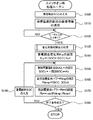
次に、実施例のハイブリッド自動車20の動作、特に、ユーザによりSOC回復指示スイッチ90がオンされたときの動作について説明する。図2は、HVECU70により実行されるスイッチオン時処理ルーチンの一例を示すフローチャートである。このルーチンは、ユーザによりSOC回復指示スイッチ90がオンされたときに実行される。
Next, the operation of the
SOC回復指示スイッチオン時処理ルーチンの実行されると、HVECU70のCPU72は、バッテリECU52から蓄電割合SOCを入力する処理を実行し(ステップS100)、目標蓄電割合SOC*と目標充電時間tc*とを設定するための目標値選択画面の画面情報をタッチパネル98に送信し(ステップS110)、タッチパネル98から目標蓄電割合SOC*と目標充電時間tc*とが入力されるまで待つ(ステップS120)。図3は、タッチパネル98に表示される目標値選択画面の一例を示す説明図である。タッチパネル98には、「満充電」,「途中まで充電」の文字を含む矩形のアイコンI10,I11と、目標充電時間を示す文字を含むアイコンI12と、「+」,「−」の文字を含むアイコンI13とが視認可能に表示されている。ユーザが表示されているアイコンI10,I11のうちの一つに触れると、タッチパネル98は、触れられたアイコンの位置情報に基づいて触れられたアイコンに表示されている充電状態の情報をユーザが入力した目標蓄電割合SOC*としてHVECU70に送信する。アイコンI13は、アイコンI12に表示される時間を設定するために用いられる。アイコンI13の「+」の文字をユーザが触れる度にアイコンI12に表示される目標時間が増加し、アイコンI13の「−」の文字をユーザが触れる度にアイコンI12に表示される目標時間が減少する。ユーザがアイコンI13を触れない状態が所定時間(例えば、10秒など)継続すると、タッチパネル98は、アイコンI13に表示されている時間を目標充電時間tc*としてHVECU70に送信する。このとき、アイコンI10,I12のうち、ユーザが触れたアイコンの色を変更するものとしたり、アイコン全体が点滅するものとしてもよい。
When the SOC recovery instruction switch-on processing routine is executed, the
こうして目標蓄電割合SOC*と目標充電時間tc*とが入力されると、後述する推定所要時間表示処理を実行し(ステップS130)、入力された目標蓄電割合SOC*から現在の蓄電割合SOCを減じたものを目標充電時間tc*で除して蓄電割合変化率Ksを設定し(ステップS140)、制御用目標蓄電割合SOCc*に蓄電割合変化率Ksを加えたものを制御用目標蓄電割合SOCc*に再設定する(ステップS150)。ここで、制御用目標蓄電割合SOCc*には、初期値としてステップS100の処理で入力された蓄電割合SOCが設定されるものとした。 When the target power storage rate SOC * and the target charge time tc * are thus input, an estimated required time display process described later is executed (step S130), and the current power storage rate SOC is subtracted from the input target power storage rate SOC *. Is divided by the target charging time tc * to set the storage rate change rate Ks (step S140), and the control target storage rate SOCc * plus the storage rate change rate Ks is set as the control target storage rate SOCc *. (Step S150). Here, the power storage ratio SOC input in the process of step S100 is set as the initial value in the control target power storage ratio SOCc *.
こうして制御用目標蓄電割合SOCc*を設定したら、高電圧バッテリ50の蓄電割合SOCと制御用目標蓄電割合SOCc*とROM74に記憶されている仮充放電要求パワー設定マップとを用いて蓄電割合SOCを制御用目標蓄電割合SOCc*にするパワーである仮充放電要求パワーPbtmpを設定する(ステップS160)。仮充放電要求パワー設定マップの一例を図4に示す。図示するように、仮充放電要求パワーPbtmpは、蓄電割合SOCが制御用目標蓄電割合SOCc*より大きいときには制御用目標蓄電割合SOCc*と蓄電割合SOCとの差を打ち消すようにこの差が大きくなるほど絶対値が大きくなる傾向の負の値のパワーが設定され、蓄電割合SOCが制御用目標蓄電割合SOCc*より小さいときには制御用目標蓄電割合SOCc*と蓄電割合SOCとの差を打ち消すようにこの差が大きくなるほど大きくなる傾向の正の値のパワーが設定される。このように仮充放電要求パワーPbtmpを設定することにより、蓄電割合SOCを制御用目標蓄電割合SOCc*にすることができる。なお、仮充放電要求パワー設定マップは、制御用目標蓄電割合SOCc*毎にROM74に記憶されているものとする。
When the control target power storage rate SOCc * is thus set, the power storage rate SOC is calculated using the power storage rate SOC of the high-
こうして仮充放電要求パワーPbtmpを設定したら、仮充放電要求パワーPbtmpと高電圧バッテリ50の許容される充電量の上限値である上限充電パワーPbmaxとのうち小さい方の値を充放電要求パワーPb*として設定する(ステップS170)。このように充放電要求パワーPb*を設定すると、上述したハイブリッド走行優先モードによって、設定した充放電要求パワーPb*に走行用パワーPdrv*を加えたパワーをエンジン22から出力しながら走行するようエンジン22やモータMG1,MG2が制御される。これにより、エンジン22から出力されるパワーを用いてモータMG1で発電した電力で高電圧バッテリ50を充電しながら走行することができる。
When the temporary charge / discharge required power Pbtmp is set in this way, the smaller one of the temporary charge / discharge required power Pbtmp and the upper limit charge power Pbmax that is the upper limit value of the allowable charge amount of the high-
こうして充放電要求パワーPb*を設定したら、続いて、SOC回復指示スイッチ90がオフされたり、高電圧バッテリ50の蓄電割合SOCが目標蓄電割合SOC*に達したときなど、所定の終了条件が成立したか否かを調べる(ステップS180)。所定の終了条件が成立していないときには、バッテリECU52が蓄電割合SOCを入力し(ステップS190)、ステップS150の処理に戻り、制御用蓄電割合SOCc*を設定する。そして、所定の終了条件が成立するまで、ステップS150〜S190の処理を繰り返して、制御用目標蓄電割合SOCc*に蓄電割合変化率Ksを加えたものを制御用目標蓄電割合SOCc*に再設定し、高電圧バッテリ50の蓄電割合SOCと制御用目標蓄電割合SOCc*とROM74に記憶されている充放電要求パワー設定マップとを用いて仮充放電要求パワーPb*を設定し、仮充放電要求パワーPbtmpと上限充電パワーPbmaxとのうち小さい方の値を充放電要求パワーPb*として設定し、バッテリECU52から蓄電割合SOCを入力する。こうした処理により、上限充放電パワーPbmaxの範囲内のパワーで高電圧バッテリ50を充電するから、蓄電割合SOCを目標蓄電割合SOC*に向けて変化させることができる。このとき、蓄電割合SOCをユーザが入力した目標充電時間tc*を用いて設定した蓄電割合変化率Ksに基づく変化量で変化させることができるから、SOC回復指示スイッチ90がオンされたら直ちに蓄電割合SOCを目標蓄電割合SOC*に近づけるものに比して、蓄電割合SOCをユーザが入力した目標充電時間tc*または目標充電時間tc*で目標蓄電割合SOC*にすることができ、ユーザの所望するタイミングにより近いタイミングで蓄電割合SOCを目標蓄電割合SOC*にすることができる。
After the charge / discharge required power Pb * is set in this way, a predetermined termination condition is satisfied, for example, when the SOC
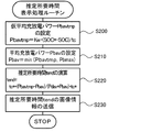
次に、ステップS120で実行される推定所要時間表示処理について説明する。図5は、推定所要時間表示処理の一例を示すフローチャートである。充電終了推定時間表示処理では、次式(1)を用いて目標充電時間tc*で現在の蓄電割合SOCを目標蓄電割合SOC*にするために単位時間当たりに高電圧バッテリ50で充放電が要求されるパワーを仮平均充放電パワーPbavtmpとして設定し(ステップS200)、仮平均充放電パワーPbavtmpとステップS170の処理で用いた上限充電パワーPbmaxとのうち小さい方の値を平均充放電パワーPbavとして設定する(ステップS210)。式(1)中、「Kw」は、高電圧バッテリ50の蓄電割合SOCを電力(パワー)に換算するための換算係数である。
Next, the estimated required time display process executed in step S120 will be described. FIG. 5 is a flowchart illustrating an example of the estimated required time display process. In the charging end estimated time display process, charging / discharging is required at the
Pbavtmp=Kw・(SOC*-SOC)/tc (1) Pbavtmp = Kw ・ (SOC * -SOC) / tc (1)
こうして平均充放電パワーPbavを設定したら、目標充電時間tc*と平均充放電パワーPbavと仮平均充放電パワーPbavtmpと高電圧バッテリ50を充電しているときの車両の平均的な走行用パワーであると予想される予想走行パワーPdavとを用いて、次式(2)により、SOC回復指示スイッチ90がオンされてから車両が予想走行パワーPdavで走行したときに蓄電割合SOCが目標蓄電割合SOC*に至るまでの所要時間と推定される推定所要時間tendを演算し(ステップS220)、推定所要時間tendがタッチパネル98に表示されるようタッチパネル98へ画像情報を出力して(ステップS230)、本ルーチンを終了する。図6にタッチパネル98に推定所要時間tendが表示されている様子の一例を示す。ここで、予想走行パワーPavは、前回イグニッションスイッチ80がオンされてからオフされるまでの1トリップにおけるアクセル開度Accと車速Vとに基づく走行要求パワーPdrv*の平均値を用いるものとした。高電圧バッテリ50には上限充放電パワーPbmaxまでしか充電が許容されないため、SOC回復指示スイッチ90がオンされてから蓄電割合SOCが目標蓄電割合SOC*に至るまでの実際の所要時間は、ユーザが入力した目標充電時間tc*からずれる場合がある。こうしたずれが生じると、ユーザが入力した目標充電時間tc*を経過したにも拘わらず高電圧バッテリ50の充電が終わらないためユーザが違和感を覚えることがあるが、推定所要時間tendを演算してタッチパネル98に表示することにより、ユーザが入力した目標充電時間tc*と実際に高電圧バッテリ50の充電が終了する時間との間にずれ生じることをユーザに報知することができ、ユーザに違和感を与えることを抑制することができる。また、推定所要時間tendを演算する際に前回イグニッションスイッチ80がオンされてからオフされるまでの1トリップにおける走行要求パワーPdrv*の平均値を用いるものとしたから、アクセルの操作の仕方などユーザの個人の運転の癖などを反映させることができ、より精度よく推定所要時間tendを演算することができる。
If the average charge / discharge power Pbav is set in this way, the target charge time tc *, the average charge / discharge power Pbav, the temporary average charge / discharge power Pbavtmp, and the average running power of the vehicle when charging the
tend=tc*+(Pbavtmp-Pbav)・tc*/ (Pdav+Pbav) (2) tend = tc * + (Pbavtmp-Pbav) ・ tc * / (Pdav + Pbav) (2)
以上説明した実施例のハイブリッド自動車20では、SOC回復指示スイッチ90がオンされたときには、SOC回復指示スイッチ90がオンされてからユーザにより入力された目標充電時間tc*を経過したときに蓄電割合SOCが目標蓄電割合SOC*になるよう上限パワーPbmaxの範囲内で設定される充放電要求パワーPb*がエンジン22から出力されるようエンジン22やモータMG1,MG2を制御することにより、ユーザが所望するタイミングによりタイミングで高電圧バッテリ50の蓄電割合SOCを目標蓄電割合SOC*にすることができる。
In the
また、目標充電時間tc*と平均充放電パワーPbavと仮平均充放電パワーPbavtmpと予想走行パワーPdavとを用いて推定所要時間tendを演算してタッチパネル98に表示することにより、ユーザが入力した目標充電時間tc*と実際に高電圧バッテリ50の充電が終了する時間との間にずれ生じることをユーザに視認させることができ、こうしたずれが生じることによりユーザに違和感を与えることを抑制することができる。
Further, by calculating the estimated required time tend using the target charging time tc *, the average charging / discharging power Pbav, the temporary average charging / discharging power Pbavtmp, and the expected traveling power Pdav and displaying the estimated required time tend on the
実施例のハイブリッド自動車20では、予想走行パワーPavとして、前回イグニッションスイッチ80がオンされてからオフされるまでの1トリップにおけるアクセル開度Accと車速Vとに基づく走行要求パワーPdrv*の平均値を用いるものとしたが、経路案内を行なうナビゲーションシステムを搭載している車両では、SOC回復指示スイッチ90がオンされた地点から目的地までの道路状況(例えば、路面の勾配、街中であるか比較的郊外かなど)や走行距離から予想走行パワーPavを演算するものとしてもよい。
In the
実施例のハイブリッド自動車20では、ステップS220の処理で、目標充電時間tc*と平均充放電パワーPbavと仮平均充放電パワーPbavtmpと予想走行パワーPdavとを用いて推定所要時間tendを演算するものとしたが、ユーザから入力された目標蓄電割合SOC*と目標充電時間tcと蓄電割合SOCと推定所要時間tendとの関係を予め実験や解析などで求めておき、目標蓄電割合SOC*と目標充電時間tcと蓄電割合SOCとが与えられると求めた関係から推定所要時間tendを導出するもとしてもよい。
In the
実施例のハイブリッド自動車20では、図2のステップS110〜S140の処理で、ユーザにより入力された目標蓄電割合SOC*と目標充電時間tc*とを用いて設定される蓄電割合変化率Ksを用いてステップS150以降の処理を実行するものとしたが、ユーザが目標蓄電割合SOC*および目標充電時間tc*に代えて蓄電割合変化率Ksを入力するものとし、入力した蓄電割合変化率Ksを用いてステップS150以降の処理を実行するものとしてもよい。
In the
実施例のハイブリッド自動車20では、推定所要時間tendをタッチパネル98に表示するものとしたが、こうしたタッチパネル98に表示されるものに限定されるものではなく、図示しないスピーカから音声によりユーザに報知するものとしてもよい。
In the
実施例のハイブリッド自動車20では、モータMG2からの動力を駆動軸36に出力するものとしたが、図7の変形例のハイブリッド自動車120に例示するように、モータMG2からの動力を駆動軸36が接続された車軸(駆動輪38a,38bが接続された車軸)とは異なる車軸(図7における車輪39a,39bに接続された車軸)に接続するものとしてもよい。
In the
実施例のハイブリッド自動車20では、エンジン22からの動力をプラネタリギヤ30を介して駆動輪38a,38bに接続された駆動軸36に出力するものとしたが、図8の変形例のハイブリッド自動車220に例示するように、エンジン22のクランクシャフトに接続されたインナーロータ232と駆動輪38a,38bに動力を出力する駆動軸36に接続されたアウターロータ234とを有しエンジン22からの動力の一部を駆動軸36に伝達すると共に残余の動力を電力に変換する対ロータ電動機230を備えるものとしてもよい。
In the
実施例のハイブリッド自動車20では、エンジン22からの動力をプラネタリギヤ30を介して駆動輪38a,38bに接続された駆動軸36に出力すると共にモータMG2からの動力を駆動軸36に出力するものとしたが、図9の変形例のハイブリッド自動車320に例示するように、走行用の動力を出力するモータMG2と、エンジン22からの動力により発電するモータMG1と、を備えるいわゆるシリーズ型のハイブリッド車としても構わない。また、駆動輪38a,38bに接続された駆動軸36に無段変速機を介してモータを取り付けると共にモータの回転軸にクラッチを介してエンジン22を接続する構成とし、エンジン22からの動力をモータの回転軸と無段変速機とを介して駆動軸に出力すると共にモータからの動力を無段変速機を介して駆動軸に出力するハイブリッド車としても構わない。さらに、こうした外部電源からの交流電力を直流電力に変換してバッテリを充電するためのDC/DCコンバータやAC/DCコンバータを有する充電器60を備えるいわゆるプラグインハイブリッド車に適用されるものに限定されるものではなく、図10の変形例のハイブリッド自動車420に例示するように、プラネタリギヤ30に接続されたエンジン22およびモータMG1と、駆動軸36に動力を入出力可能なモータMG2と、を備えるハイブリッド自動車420に適用するものとしてもよい。
In the
実施例の主要な要素と課題を解決するための手段の欄に記載した発明の主要な要素との対応関係について説明する。実施例では、エンジン22が「エンジン」に相当し、モータMG1やモータMG2が「モータ」に相当し、高電圧バッテリ50が「バッテリ」に相当し、SOC回復指示スイッチ90がオンされたときには、SOC回復指示スイッチ90がオンされてからユーザにより入力された目標充電時間tc*を経過したときに蓄電割合SOCが目標蓄電割合SOC*になるよう上限パワーPbmaxの範囲内で充放電要求パワーPb*を設定する図2のスイッチオン時処理ルーチンや、設定された充放電要求パワーPb*と走行要求パワーPdrv*との和のパワーがエンジン22から出力されるようエンジン22やモータMG1,MG2を制御する処理を実行するHVECU70とエンジンECU24とモータECU40とが「制御手段」に相当する。
The correspondence between the main elements of the embodiment and the main elements of the invention described in the column of means for solving the problems will be described. In the embodiment, when the
ここで、「エンジン」としては、ガソリンまたは軽油などの炭化水素系の燃料により動力を出力するものに限定されるものではなく、水素エンジンなど走行用の動力を出力可能なものであれば如何なるタイプのエンジンであっても構わない。「モータ」としては、同期発電電動機として構成されたモータMG1やモータMG2に限定されるものではなく、誘導電動機など、エンジンからの動力を用いて発電するものであれば如何なるタイプの電動機であっても構わない。「バッテリ」としては、二次電池としての高電圧バッテリ50に限定されるものではなく、モータと電力をやりとりするものであれば如何なるものとしても構わない。「制御手段」としては、HVECU70とエンジンECU24とモータECU40とからなる組み合わせに限定されるものではなく単一の電子制御ユニットにより構成されるなどとしてもよい。また、「制御手段」としては、SOC回復指示スイッチ90がオンされてからユーザにより入力された目標充電時間tc*を経過したときに蓄電割合SOCが目標蓄電割合SOC*になるよう上限パワーPbmaxの範囲内で充放電要求パワーPb*を設定し、設定された充放電要求パワーPb*と走行要求パワーPdrv*との和のパワーがエンジン22から出力されるようエンジン22やモータMG1,MG2を制御するものに限定されるものではなく、バッテリの充電の促進が指示されたときにバッテリの蓄電量の増加速度が指示されたときには、指示された増加速度でバッテリの蓄電量が増加するようエンジンとモータとを制御するものであれば如何なるものとしても構わない。
Here, the “engine” is not limited to one that outputs power using hydrocarbon fuel such as gasoline or light oil, but any type that can output driving power such as a hydrogen engine. It may be an engine. The “motor” is not limited to the motor MG1 or the motor MG2 configured as a synchronous generator motor, but may be any type of electric motor that generates power using power from the engine, such as an induction motor. It doesn't matter. The “battery” is not limited to the
なお、実施例の主要な要素と課題を解決するための手段の欄に記載した発明の主要な要素との対応関係は、実施例が課題を解決するための手段の欄に記載した発明を実施するための形態を具体的に説明するための一例であることから、課題を解決するための手段の欄に記載した発明の要素を限定するものではない。即ち、課題を解決するための手段の欄に記載した発明についての解釈はその欄の記載に基づいて行なわれるべきものであり、実施例は課題を解決するための手段の欄に記載した発明の具体的な一例に過ぎないものである。 The correspondence between the main elements of the embodiment and the main elements of the invention described in the column of means for solving the problem is the same as that of the embodiment described in the column of means for solving the problem. Therefore, the elements of the invention described in the column of means for solving the problems are not limited. That is, the interpretation of the invention described in the column of means for solving the problems should be made based on the description of the column, and the examples are those of the invention described in the column of means for solving the problems. It is only a specific example.
以上、本発明を実施するための形態について実施例を用いて説明したが、本発明はこうした実施例に何等限定されるものではなく、本発明の要旨を逸脱しない範囲内において、種々なる形態で実施し得ることは勿論である。 As mentioned above, although the form for implementing this invention was demonstrated using the Example, this invention is not limited at all to such an Example, In the range which does not deviate from the summary of this invention, it is with various forms. Of course, it can be implemented.
本発明は、ハイブリッド車両の製造産業などに利用可能である。 The present invention is applicable to the hybrid vehicle manufacturing industry and the like.
20,120,220,320,420 ハイブリッド自動車、22 エンジン、24 エンジン用電子制御ユニット(エンジンECU)、26 クランクシャフト、30 プラネタリギヤ、36 駆動軸、37 デファレンシャルギヤ、38a,38b 駆動輪、39a,39b 車輪、40 モータ用電子制御ユニット(モータECU)、41,42 インバータ、43,44 回転位置検出センサ、50 高電圧バッテリ、51a 電圧センサ、51b 電流センサ、51c 温度センサ、52 バッテリ用電子制御ユニット(バッテリECU)、54a 高電圧系電力ライン、54b 低電圧系電力ライン、56 システムメインリレー、57 DC/DCコンバータ、58 低電圧バッテリ、59 補機、60 充電器、62 リレー、64 DC/DCコンバータ、66 AC/DCコンバータ、68 電源プラグ、69 接続検出センサ、70 ハイブリッド用電子制御ユニット(HVECU)、72 CPU、74 ROM、76 RAM、80 イグニッションスイッチ、81 シフトレバー、82 シフトポジションセンサ、83 アクセルペダル、84 アクセルペダルポジションセンサ、85 ブレーキペダル、86 ブレーキペダルポジションセンサ、88 車速センサ、90 SOC回復指示スイッチ、94 コンセント、96 DC/AC変換器、98 タッチパネル、230 対ロータ電動機、232 インナーロータ、234 アウターロータ、MG1,MG2 モータ。 20, 120, 220, 320, 420 Hybrid vehicle, 22 engine, 24 electronic control unit for engine (engine ECU), 26 crankshaft, 30 planetary gear, 36 drive shaft, 37 differential gear, 38a, 38b drive wheel, 39a, 39b Wheel, 40 Motor electronic control unit (motor ECU), 41, 42 Inverter, 43, 44 Rotation position detection sensor, 50 High voltage battery, 51a Voltage sensor, 51b Current sensor, 51c Temperature sensor, 52 Electronic control unit for battery ( Battery ECU), 54a High voltage system power line, 54b Low voltage system power line, 56 System main relay, 57 DC / DC converter, 58 Low voltage battery, 59 Auxiliary equipment, 60 Charger, 62 Relay, 64 DC / DC converter, 66 AC / DC converter, 68 power plug, 69 connection detection sensor, 70 hybrid electronic control unit (HVECU), 72 CPU, 74 ROM, 76 RAM, 80 ignition switch, 81 shift lever, 82 shift position sensor, 83 accelerator pedal, 84 accelerator pedal position sensor, 85 brake pedal, 86 brake pedal position sensor, 88 vehicle speed sensor, 90 SOC recovery instruction switch, 94 outlet, 96 DC / AC converter, 98 touch panel, 230 to rotor motor, 232 inner Rotor, 234 Outer rotor, MG1, MG2 motor.
Claims (5)
前記バッテリの充電の促進が指示されたときに前記バッテリの蓄電量の増加速度が指示されたときには、前記指示された増加速度で前記バッテリの蓄電量が増加するよう前記エンジンと前記モータとを制御する制御手段
を備えるハイブリッド車両。 A hybrid vehicle comprising an engine, a motor that generates electric power using power from the engine, and a battery that exchanges electric power with the motor,
When an instruction to increase the amount of charge of the battery is instructed when promotion of charging of the battery is instructed, the engine and the motor are controlled so that the amount of charge of the battery increases at the instructed increase speed. A hybrid vehicle comprising a control means.
前記バッテリの蓄電量の増加速度は、目標蓄電量に至るまでの充電所要時間が指示されることで指示され、
前記増加速度は、前記充電の促進が指示されてから前記充電所要時間を経過したとき以降に前記蓄電量が前記目標蓄電量になる速度である
ハイブリッド車両。 The hybrid vehicle according to claim 1,
The rate of increase in the amount of electricity stored in the battery is instructed by instructing the time required for charging to reach the target amount of electricity stored,
The increase speed is a speed at which the charged amount becomes the target charged amount after the time required for charging has elapsed after the charge promotion is instructed.
前記モータは、前記エンジンからの動力で発電し、
前記制御手段は、前記バッテリの充電の促進が指示されたときには、前記蓄電量を前記目標蓄電量にするために前記バッテリの充電に要求される充電要求パワーを前記バッテリの充電に許容される電力の上限値である上限充電パワーで制限したパワーと、前記走行要求パワーと、の和のパワーが前記エンジンから出力されるよう前記エンジンを制御する手段である
ハイブリッド車両。 The hybrid vehicle according to claim 2,
The motor generates power with power from the engine,
When the control unit is instructed to promote the charging of the battery, the charging request power required for charging the battery to make the charged amount equal to the target charged amount is the power allowed for charging the battery. The hybrid vehicle is a means for controlling the engine so that the sum of the power limited by the upper limit charging power that is the upper limit value of the power and the required travel power is output from the engine.
情報を報知する報知手段
を備え、
前記制御手段は、前記バッテリの充電の促進が指示されたときには、前記充電の促進の指示がなされてから前記蓄電量が前記目標蓄電量に至るまでの所要時間の推定値である推定所要時間が前記報知手段で報知されるよう前記報知手段を制御する手段である
ハイブリッド車両。 A hybrid vehicle according to claim 2 or 3,
Provided with an informing means for informing information,
When the control unit is instructed to promote charging of the battery, the control unit estimates an estimated required time that is an estimated value of the required time from when the instruction to promote charging is made until the amount of stored electricity reaches the target amount of stored power. A hybrid vehicle which is means for controlling the notification means so as to be notified by the notification means.
前記制御手段は、前記バッテリの蓄電量が前記目標蓄電量に至るまでの前記走行要求パワーの推定値である推定走行パワーと、前記バッテリの蓄電量が前記目標蓄電量に至るまでの前記バッテリを充電するパワーの平均値である平均充電パワーを前記上限充電パワーで制限したものと、前記入力された充電所要時間と、を用いて前記推定所要時間を演算する手段である
ハイブリッド車両。 The hybrid vehicle according to claim 4,
The control means includes an estimated travel power that is an estimated value of the required travel power until the battery storage amount reaches the target storage amount, and the battery until the battery storage amount reaches the target storage amount. A hybrid vehicle, which is a means for calculating the estimated required time by using an average charge power that is an average value of power to be charged limited by the upper limit charge power and the input required charge time.
Priority Applications (2)
| Application Number | Priority Date | Filing Date | Title |
|---|---|---|---|
| JP2013080329A JP2014201245A (en) | 2013-04-08 | 2013-04-08 | Hybrid vehicle |
| PCT/IB2014/000560 WO2014167413A1 (en) | 2013-04-08 | 2014-04-08 | Hybrid vehicle |
Applications Claiming Priority (1)
| Application Number | Priority Date | Filing Date | Title |
|---|---|---|---|
| JP2013080329A JP2014201245A (en) | 2013-04-08 | 2013-04-08 | Hybrid vehicle |
Publications (1)
| Publication Number | Publication Date |
|---|---|
| JP2014201245A true JP2014201245A (en) | 2014-10-27 |
Family
ID=50588760
Family Applications (1)
| Application Number | Title | Priority Date | Filing Date |
|---|---|---|---|
| JP2013080329A Pending JP2014201245A (en) | 2013-04-08 | 2013-04-08 | Hybrid vehicle |
Country Status (2)
| Country | Link |
|---|---|
| JP (1) | JP2014201245A (en) |
| WO (1) | WO2014167413A1 (en) |
Cited By (3)
| Publication number | Priority date | Publication date | Assignee | Title |
|---|---|---|---|---|
| JP2017030668A (en) * | 2015-08-05 | 2017-02-09 | トヨタ自動車株式会社 | Hybrid automobile |
| JP2017154688A (en) * | 2016-03-04 | 2017-09-07 | トヨタ自動車株式会社 | Hybrid vehicle |
| KR102057146B1 (en) | 2019-09-26 | 2019-12-18 | 한국전력공사 | Intelligent charging method using intelligent charging station for electric vehicle |
Families Citing this family (1)
| Publication number | Priority date | Publication date | Assignee | Title |
|---|---|---|---|---|
| JP2014201245A (en) * | 2013-04-08 | 2014-10-27 | トヨタ自動車株式会社 | Hybrid vehicle |
Citations (11)
| Publication number | Priority date | Publication date | Assignee | Title |
|---|---|---|---|---|
| JP2003111208A (en) * | 2001-09-28 | 2003-04-11 | Pioneer Electronic Corp | Hybrid car |
| JP2010100136A (en) * | 2008-10-22 | 2010-05-06 | Toyota Motor Corp | Hybrid vehicle and control method of the same |
| JP2010213373A (en) * | 2009-03-06 | 2010-09-24 | Fujitsu Ten Ltd | Controller and control method |
| JP2011093335A (en) * | 2009-10-27 | 2011-05-12 | Toyota Motor Corp | Controller for hybrid vehicle |
| DE102010031289A1 (en) * | 2010-07-13 | 2012-01-19 | Bayerische Motoren Werke Aktiengesellschaft | Vehicle, particularly hybrid or electric vehicle, has battery to supply power to electrical machine when electrical machine is operated as electric motor, and supplied power is stored when electrical machine is operated as generator |
| JP2012046121A (en) * | 2010-08-30 | 2012-03-08 | Mitsubishi Motors Corp | Generation control device of hybrid vehicle |
| JP4930640B2 (en) * | 2010-03-18 | 2012-05-16 | トヨタ自動車株式会社 | Electric drive vehicle |
| DE102011075145A1 (en) * | 2011-05-03 | 2012-11-08 | Zf Friedrichshafen Ag | Method for operating a drive train of a hybrid vehicle |
| JP2013009460A (en) * | 2011-06-22 | 2013-01-10 | Mitsubishi Motors Corp | Charging inlet lid control device |
| WO2013046252A1 (en) * | 2011-09-26 | 2013-04-04 | トヨタ自動車株式会社 | Vehicle and control method for vehicle |
| WO2014167413A1 (en) * | 2013-04-08 | 2014-10-16 | Toyota Jidosha Kabushiki Kaisha | Hybrid vehicle |
-
2013
- 2013-04-08 JP JP2013080329A patent/JP2014201245A/en active Pending
-
2014
- 2014-04-08 WO PCT/IB2014/000560 patent/WO2014167413A1/en active Application Filing
Patent Citations (11)
| Publication number | Priority date | Publication date | Assignee | Title |
|---|---|---|---|---|
| JP2003111208A (en) * | 2001-09-28 | 2003-04-11 | Pioneer Electronic Corp | Hybrid car |
| JP2010100136A (en) * | 2008-10-22 | 2010-05-06 | Toyota Motor Corp | Hybrid vehicle and control method of the same |
| JP2010213373A (en) * | 2009-03-06 | 2010-09-24 | Fujitsu Ten Ltd | Controller and control method |
| JP2011093335A (en) * | 2009-10-27 | 2011-05-12 | Toyota Motor Corp | Controller for hybrid vehicle |
| JP4930640B2 (en) * | 2010-03-18 | 2012-05-16 | トヨタ自動車株式会社 | Electric drive vehicle |
| DE102010031289A1 (en) * | 2010-07-13 | 2012-01-19 | Bayerische Motoren Werke Aktiengesellschaft | Vehicle, particularly hybrid or electric vehicle, has battery to supply power to electrical machine when electrical machine is operated as electric motor, and supplied power is stored when electrical machine is operated as generator |
| JP2012046121A (en) * | 2010-08-30 | 2012-03-08 | Mitsubishi Motors Corp | Generation control device of hybrid vehicle |
| DE102011075145A1 (en) * | 2011-05-03 | 2012-11-08 | Zf Friedrichshafen Ag | Method for operating a drive train of a hybrid vehicle |
| JP2013009460A (en) * | 2011-06-22 | 2013-01-10 | Mitsubishi Motors Corp | Charging inlet lid control device |
| WO2013046252A1 (en) * | 2011-09-26 | 2013-04-04 | トヨタ自動車株式会社 | Vehicle and control method for vehicle |
| WO2014167413A1 (en) * | 2013-04-08 | 2014-10-16 | Toyota Jidosha Kabushiki Kaisha | Hybrid vehicle |
Cited By (3)
| Publication number | Priority date | Publication date | Assignee | Title |
|---|---|---|---|---|
| JP2017030668A (en) * | 2015-08-05 | 2017-02-09 | トヨタ自動車株式会社 | Hybrid automobile |
| JP2017154688A (en) * | 2016-03-04 | 2017-09-07 | トヨタ自動車株式会社 | Hybrid vehicle |
| KR102057146B1 (en) | 2019-09-26 | 2019-12-18 | 한국전력공사 | Intelligent charging method using intelligent charging station for electric vehicle |
Also Published As
| Publication number | Publication date |
|---|---|
| WO2014167413A1 (en) | 2014-10-16 |
Similar Documents
| Publication | Publication Date | Title |
|---|---|---|
| JP5206880B2 (en) | Hybrid vehicle and parameter display method of hybrid vehicle | |
| JP2014201246A (en) | Hybrid vehicle | |
| JP6156419B2 (en) | vehicle | |
| JP5714239B2 (en) | Vehicle control system | |
| EP2612787A1 (en) | Electric-powered vehicle and control method therefor | |
| JP6090273B2 (en) | Hybrid car | |
| JP5062288B2 (en) | Engine starter | |
| JP6149806B2 (en) | Hybrid vehicle | |
| JP2013159214A (en) | Controller for hybrid vehicle | |
| JP5845930B2 (en) | Electric traveling distance display device for a vehicle capable of traveling using at least an electric motor | |
| JP5887959B2 (en) | Display device for hybrid vehicle | |
| JP2009198223A (en) | Vehicle and its control method | |
| JP2011057117A (en) | Hybrid vehicle | |
| JP2014205380A (en) | Hybrid vehicle | |
| JP6414111B2 (en) | Display device | |
| JP2014201245A (en) | Hybrid vehicle | |
| JP2011073564A (en) | Hybrid vehicle and method for controlling the same | |
| JP6947051B2 (en) | Hybrid car | |
| JP2012186906A (en) | Electric vehicle and charging apparatus | |
| JP2010132141A (en) | Power output device, vehicle, drive device and control method for the power output device | |
| JP5696755B2 (en) | Control device for hybrid vehicle | |
| JP2012106672A (en) | Hybrid vehicle | |
| JP6361299B2 (en) | Hybrid vehicle | |
| JP5733331B2 (en) | Vehicle control system | |
| JP2013129379A (en) | Control device of vehicle |
Legal Events
| Date | Code | Title | Description |
|---|---|---|---|
| A977 | Report on retrieval |
Free format text: JAPANESE INTERMEDIATE CODE: A971007 Effective date: 20150212 |
|
| A131 | Notification of reasons for refusal |
Free format text: JAPANESE INTERMEDIATE CODE: A131 Effective date: 20150217 |
|
| A521 | Written amendment |
Free format text: JAPANESE INTERMEDIATE CODE: A523 Effective date: 20150415 |
|
| A131 | Notification of reasons for refusal |
Free format text: JAPANESE INTERMEDIATE CODE: A131 Effective date: 20150609 |
|
| A02 | Decision of refusal |
Free format text: JAPANESE INTERMEDIATE CODE: A02 Effective date: 20151020 |