WO2013042681A1 - Method for manufacturing polarizing plate - Google Patents
Method for manufacturing polarizing plate Download PDFInfo
- Publication number
- WO2013042681A1 WO2013042681A1 PCT/JP2012/073906 JP2012073906W WO2013042681A1 WO 2013042681 A1 WO2013042681 A1 WO 2013042681A1 JP 2012073906 W JP2012073906 W JP 2012073906W WO 2013042681 A1 WO2013042681 A1 WO 2013042681A1
- Authority
- WO
- WIPO (PCT)
- Prior art keywords
- roll
- film
- adhesive
- polarizing plate
- active energy
- Prior art date
Links
Images

Classifications
-
- B—PERFORMING OPERATIONS; TRANSPORTING
- B29—WORKING OF PLASTICS; WORKING OF SUBSTANCES IN A PLASTIC STATE IN GENERAL
- B29C—SHAPING OR JOINING OF PLASTICS; SHAPING OF MATERIAL IN A PLASTIC STATE, NOT OTHERWISE PROVIDED FOR; AFTER-TREATMENT OF THE SHAPED PRODUCTS, e.g. REPAIRING
- B29C65/00—Joining or sealing of preformed parts, e.g. welding of plastics materials; Apparatus therefor
- B29C65/02—Joining or sealing of preformed parts, e.g. welding of plastics materials; Apparatus therefor by heating, with or without pressure
- B29C65/14—Joining or sealing of preformed parts, e.g. welding of plastics materials; Apparatus therefor by heating, with or without pressure using wave energy, i.e. electromagnetic radiation, or particle radiation
- B29C65/1429—Joining or sealing of preformed parts, e.g. welding of plastics materials; Apparatus therefor by heating, with or without pressure using wave energy, i.e. electromagnetic radiation, or particle radiation characterised by the way of heating the interface
- B29C65/1435—Joining or sealing of preformed parts, e.g. welding of plastics materials; Apparatus therefor by heating, with or without pressure using wave energy, i.e. electromagnetic radiation, or particle radiation characterised by the way of heating the interface at least passing through one of the parts to be joined, i.e. transmission welding
-
- B—PERFORMING OPERATIONS; TRANSPORTING
- B29—WORKING OF PLASTICS; WORKING OF SUBSTANCES IN A PLASTIC STATE IN GENERAL
- B29C—SHAPING OR JOINING OF PLASTICS; SHAPING OF MATERIAL IN A PLASTIC STATE, NOT OTHERWISE PROVIDED FOR; AFTER-TREATMENT OF THE SHAPED PRODUCTS, e.g. REPAIRING
- B29C65/00—Joining or sealing of preformed parts, e.g. welding of plastics materials; Apparatus therefor
- B29C65/02—Joining or sealing of preformed parts, e.g. welding of plastics materials; Apparatus therefor by heating, with or without pressure
- B29C65/14—Joining or sealing of preformed parts, e.g. welding of plastics materials; Apparatus therefor by heating, with or without pressure using wave energy, i.e. electromagnetic radiation, or particle radiation
- B29C65/1429—Joining or sealing of preformed parts, e.g. welding of plastics materials; Apparatus therefor by heating, with or without pressure using wave energy, i.e. electromagnetic radiation, or particle radiation characterised by the way of heating the interface
- B29C65/1464—Joining or sealing of preformed parts, e.g. welding of plastics materials; Apparatus therefor by heating, with or without pressure using wave energy, i.e. electromagnetic radiation, or particle radiation characterised by the way of heating the interface making use of several radiators
-
- B—PERFORMING OPERATIONS; TRANSPORTING
- B29—WORKING OF PLASTICS; WORKING OF SUBSTANCES IN A PLASTIC STATE IN GENERAL
- B29C—SHAPING OR JOINING OF PLASTICS; SHAPING OF MATERIAL IN A PLASTIC STATE, NOT OTHERWISE PROVIDED FOR; AFTER-TREATMENT OF THE SHAPED PRODUCTS, e.g. REPAIRING
- B29C65/00—Joining or sealing of preformed parts, e.g. welding of plastics materials; Apparatus therefor
- B29C65/02—Joining or sealing of preformed parts, e.g. welding of plastics materials; Apparatus therefor by heating, with or without pressure
- B29C65/14—Joining or sealing of preformed parts, e.g. welding of plastics materials; Apparatus therefor by heating, with or without pressure using wave energy, i.e. electromagnetic radiation, or particle radiation
- B29C65/1477—Joining or sealing of preformed parts, e.g. welding of plastics materials; Apparatus therefor by heating, with or without pressure using wave energy, i.e. electromagnetic radiation, or particle radiation making use of an absorber or impact modifier
- B29C65/1483—Joining or sealing of preformed parts, e.g. welding of plastics materials; Apparatus therefor by heating, with or without pressure using wave energy, i.e. electromagnetic radiation, or particle radiation making use of an absorber or impact modifier coated on the article
-
- B—PERFORMING OPERATIONS; TRANSPORTING
- B29—WORKING OF PLASTICS; WORKING OF SUBSTANCES IN A PLASTIC STATE IN GENERAL
- B29C—SHAPING OR JOINING OF PLASTICS; SHAPING OF MATERIAL IN A PLASTIC STATE, NOT OTHERWISE PROVIDED FOR; AFTER-TREATMENT OF THE SHAPED PRODUCTS, e.g. REPAIRING
- B29C65/00—Joining or sealing of preformed parts, e.g. welding of plastics materials; Apparatus therefor
- B29C65/48—Joining or sealing of preformed parts, e.g. welding of plastics materials; Apparatus therefor using adhesives, i.e. using supplementary joining material; solvent bonding
- B29C65/4805—Joining or sealing of preformed parts, e.g. welding of plastics materials; Apparatus therefor using adhesives, i.e. using supplementary joining material; solvent bonding characterised by the type of adhesives
- B29C65/483—Reactive adhesives, e.g. chemically curing adhesives
- B29C65/4845—Radiation curing adhesives, e.g. UV light curing adhesives
-
- B—PERFORMING OPERATIONS; TRANSPORTING
- B29—WORKING OF PLASTICS; WORKING OF SUBSTANCES IN A PLASTIC STATE IN GENERAL
- B29C—SHAPING OR JOINING OF PLASTICS; SHAPING OF MATERIAL IN A PLASTIC STATE, NOT OTHERWISE PROVIDED FOR; AFTER-TREATMENT OF THE SHAPED PRODUCTS, e.g. REPAIRING
- B29C65/00—Joining or sealing of preformed parts, e.g. welding of plastics materials; Apparatus therefor
- B29C65/48—Joining or sealing of preformed parts, e.g. welding of plastics materials; Apparatus therefor using adhesives, i.e. using supplementary joining material; solvent bonding
- B29C65/52—Joining or sealing of preformed parts, e.g. welding of plastics materials; Apparatus therefor using adhesives, i.e. using supplementary joining material; solvent bonding characterised by the way of applying the adhesive
- B29C65/524—Joining or sealing of preformed parts, e.g. welding of plastics materials; Apparatus therefor using adhesives, i.e. using supplementary joining material; solvent bonding characterised by the way of applying the adhesive by applying the adhesive from an outlet device in contact with, or almost in contact with, the surface of the part to be joined
-
- B—PERFORMING OPERATIONS; TRANSPORTING
- B29—WORKING OF PLASTICS; WORKING OF SUBSTANCES IN A PLASTIC STATE IN GENERAL
- B29C—SHAPING OR JOINING OF PLASTICS; SHAPING OF MATERIAL IN A PLASTIC STATE, NOT OTHERWISE PROVIDED FOR; AFTER-TREATMENT OF THE SHAPED PRODUCTS, e.g. REPAIRING
- B29C65/00—Joining or sealing of preformed parts, e.g. welding of plastics materials; Apparatus therefor
- B29C65/48—Joining or sealing of preformed parts, e.g. welding of plastics materials; Apparatus therefor using adhesives, i.e. using supplementary joining material; solvent bonding
- B29C65/52—Joining or sealing of preformed parts, e.g. welding of plastics materials; Apparatus therefor using adhesives, i.e. using supplementary joining material; solvent bonding characterised by the way of applying the adhesive
- B29C65/526—Joining or sealing of preformed parts, e.g. welding of plastics materials; Apparatus therefor using adhesives, i.e. using supplementary joining material; solvent bonding characterised by the way of applying the adhesive by printing or by transfer from the surfaces of elements carrying the adhesive, e.g. using brushes, pads, rollers, stencils or silk screens
-
- B—PERFORMING OPERATIONS; TRANSPORTING
- B29—WORKING OF PLASTICS; WORKING OF SUBSTANCES IN A PLASTIC STATE IN GENERAL
- B29C—SHAPING OR JOINING OF PLASTICS; SHAPING OF MATERIAL IN A PLASTIC STATE, NOT OTHERWISE PROVIDED FOR; AFTER-TREATMENT OF THE SHAPED PRODUCTS, e.g. REPAIRING
- B29C66/00—General aspects of processes or apparatus for joining preformed parts
- B29C66/01—General aspects dealing with the joint area or with the area to be joined
- B29C66/05—Particular design of joint configurations
- B29C66/10—Particular design of joint configurations particular design of the joint cross-sections
- B29C66/11—Joint cross-sections comprising a single joint-segment, i.e. one of the parts to be joined comprising a single joint-segment in the joint cross-section
- B29C66/112—Single lapped joints
- B29C66/1122—Single lap to lap joints, i.e. overlap joints
-
- B—PERFORMING OPERATIONS; TRANSPORTING
- B29—WORKING OF PLASTICS; WORKING OF SUBSTANCES IN A PLASTIC STATE IN GENERAL
- B29C—SHAPING OR JOINING OF PLASTICS; SHAPING OF MATERIAL IN A PLASTIC STATE, NOT OTHERWISE PROVIDED FOR; AFTER-TREATMENT OF THE SHAPED PRODUCTS, e.g. REPAIRING
- B29C66/00—General aspects of processes or apparatus for joining preformed parts
- B29C66/01—General aspects dealing with the joint area or with the area to be joined
- B29C66/342—Preventing air-inclusions
-
- B—PERFORMING OPERATIONS; TRANSPORTING
- B29—WORKING OF PLASTICS; WORKING OF SUBSTANCES IN A PLASTIC STATE IN GENERAL
- B29C—SHAPING OR JOINING OF PLASTICS; SHAPING OF MATERIAL IN A PLASTIC STATE, NOT OTHERWISE PROVIDED FOR; AFTER-TREATMENT OF THE SHAPED PRODUCTS, e.g. REPAIRING
- B29C66/00—General aspects of processes or apparatus for joining preformed parts
- B29C66/40—General aspects of joining substantially flat articles, e.g. plates, sheets or web-like materials; Making flat seams in tubular or hollow articles; Joining single elements to substantially flat surfaces
- B29C66/41—Joining substantially flat articles ; Making flat seams in tubular or hollow articles
- B29C66/45—Joining of substantially the whole surface of the articles
-
- B—PERFORMING OPERATIONS; TRANSPORTING
- B29—WORKING OF PLASTICS; WORKING OF SUBSTANCES IN A PLASTIC STATE IN GENERAL
- B29C—SHAPING OR JOINING OF PLASTICS; SHAPING OF MATERIAL IN A PLASTIC STATE, NOT OTHERWISE PROVIDED FOR; AFTER-TREATMENT OF THE SHAPED PRODUCTS, e.g. REPAIRING
- B29C66/00—General aspects of processes or apparatus for joining preformed parts
- B29C66/70—General aspects of processes or apparatus for joining preformed parts characterised by the composition, physical properties or the structure of the material of the parts to be joined; Joining with non-plastics material
- B29C66/73—General aspects of processes or apparatus for joining preformed parts characterised by the composition, physical properties or the structure of the material of the parts to be joined; Joining with non-plastics material characterised by the intensive physical properties of the material of the parts to be joined, by the optical properties of the material of the parts to be joined, by the extensive physical properties of the parts to be joined, by the state of the material of the parts to be joined or by the material of the parts to be joined being a thermoplastic or a thermoset
- B29C66/733—General aspects of processes or apparatus for joining preformed parts characterised by the composition, physical properties or the structure of the material of the parts to be joined; Joining with non-plastics material characterised by the intensive physical properties of the material of the parts to be joined, by the optical properties of the material of the parts to be joined, by the extensive physical properties of the parts to be joined, by the state of the material of the parts to be joined or by the material of the parts to be joined being a thermoplastic or a thermoset characterised by the optical properties of the material of the parts to be joined, e.g. fluorescence, phosphorescence
- B29C66/7336—General aspects of processes or apparatus for joining preformed parts characterised by the composition, physical properties or the structure of the material of the parts to be joined; Joining with non-plastics material characterised by the intensive physical properties of the material of the parts to be joined, by the optical properties of the material of the parts to be joined, by the extensive physical properties of the parts to be joined, by the state of the material of the parts to be joined or by the material of the parts to be joined being a thermoplastic or a thermoset characterised by the optical properties of the material of the parts to be joined, e.g. fluorescence, phosphorescence at least one of the parts to be joined being opaque, transparent or translucent to visible light
- B29C66/73365—General aspects of processes or apparatus for joining preformed parts characterised by the composition, physical properties or the structure of the material of the parts to be joined; Joining with non-plastics material characterised by the intensive physical properties of the material of the parts to be joined, by the optical properties of the material of the parts to be joined, by the extensive physical properties of the parts to be joined, by the state of the material of the parts to be joined or by the material of the parts to be joined being a thermoplastic or a thermoset characterised by the optical properties of the material of the parts to be joined, e.g. fluorescence, phosphorescence at least one of the parts to be joined being opaque, transparent or translucent to visible light at least one of the parts to be joined being transparent or translucent to visible light
-
- B—PERFORMING OPERATIONS; TRANSPORTING
- B29—WORKING OF PLASTICS; WORKING OF SUBSTANCES IN A PLASTIC STATE IN GENERAL
- B29C—SHAPING OR JOINING OF PLASTICS; SHAPING OF MATERIAL IN A PLASTIC STATE, NOT OTHERWISE PROVIDED FOR; AFTER-TREATMENT OF THE SHAPED PRODUCTS, e.g. REPAIRING
- B29C66/00—General aspects of processes or apparatus for joining preformed parts
- B29C66/70—General aspects of processes or apparatus for joining preformed parts characterised by the composition, physical properties or the structure of the material of the parts to be joined; Joining with non-plastics material
- B29C66/73—General aspects of processes or apparatus for joining preformed parts characterised by the composition, physical properties or the structure of the material of the parts to be joined; Joining with non-plastics material characterised by the intensive physical properties of the material of the parts to be joined, by the optical properties of the material of the parts to be joined, by the extensive physical properties of the parts to be joined, by the state of the material of the parts to be joined or by the material of the parts to be joined being a thermoplastic or a thermoset
- B29C66/733—General aspects of processes or apparatus for joining preformed parts characterised by the composition, physical properties or the structure of the material of the parts to be joined; Joining with non-plastics material characterised by the intensive physical properties of the material of the parts to be joined, by the optical properties of the material of the parts to be joined, by the extensive physical properties of the parts to be joined, by the state of the material of the parts to be joined or by the material of the parts to be joined being a thermoplastic or a thermoset characterised by the optical properties of the material of the parts to be joined, e.g. fluorescence, phosphorescence
- B29C66/7338—General aspects of processes or apparatus for joining preformed parts characterised by the composition, physical properties or the structure of the material of the parts to be joined; Joining with non-plastics material characterised by the intensive physical properties of the material of the parts to be joined, by the optical properties of the material of the parts to be joined, by the extensive physical properties of the parts to be joined, by the state of the material of the parts to be joined or by the material of the parts to be joined being a thermoplastic or a thermoset characterised by the optical properties of the material of the parts to be joined, e.g. fluorescence, phosphorescence at least one of the parts to be joined being polarising
-
- B—PERFORMING OPERATIONS; TRANSPORTING
- B29—WORKING OF PLASTICS; WORKING OF SUBSTANCES IN A PLASTIC STATE IN GENERAL
- B29C—SHAPING OR JOINING OF PLASTICS; SHAPING OF MATERIAL IN A PLASTIC STATE, NOT OTHERWISE PROVIDED FOR; AFTER-TREATMENT OF THE SHAPED PRODUCTS, e.g. REPAIRING
- B29C66/00—General aspects of processes or apparatus for joining preformed parts
- B29C66/80—General aspects of machine operations or constructions and parts thereof
- B29C66/81—General aspects of the pressing elements, i.e. the elements applying pressure on the parts to be joined in the area to be joined, e.g. the welding jaws or clamps
- B29C66/814—General aspects of the pressing elements, i.e. the elements applying pressure on the parts to be joined in the area to be joined, e.g. the welding jaws or clamps characterised by the design of the pressing elements, e.g. of the welding jaws or clamps
- B29C66/8141—General aspects of the pressing elements, i.e. the elements applying pressure on the parts to be joined in the area to be joined, e.g. the welding jaws or clamps characterised by the design of the pressing elements, e.g. of the welding jaws or clamps characterised by the surface geometry of the part of the pressing elements, e.g. welding jaws or clamps, coming into contact with the parts to be joined
- B29C66/81411—General aspects of the pressing elements, i.e. the elements applying pressure on the parts to be joined in the area to be joined, e.g. the welding jaws or clamps characterised by the design of the pressing elements, e.g. of the welding jaws or clamps characterised by the surface geometry of the part of the pressing elements, e.g. welding jaws or clamps, coming into contact with the parts to be joined characterised by its cross-section, e.g. transversal or longitudinal, being non-flat
- B29C66/81421—General aspects of the pressing elements, i.e. the elements applying pressure on the parts to be joined in the area to be joined, e.g. the welding jaws or clamps characterised by the design of the pressing elements, e.g. of the welding jaws or clamps characterised by the surface geometry of the part of the pressing elements, e.g. welding jaws or clamps, coming into contact with the parts to be joined characterised by its cross-section, e.g. transversal or longitudinal, being non-flat being convex or concave
- B29C66/81422—General aspects of the pressing elements, i.e. the elements applying pressure on the parts to be joined in the area to be joined, e.g. the welding jaws or clamps characterised by the design of the pressing elements, e.g. of the welding jaws or clamps characterised by the surface geometry of the part of the pressing elements, e.g. welding jaws or clamps, coming into contact with the parts to be joined characterised by its cross-section, e.g. transversal or longitudinal, being non-flat being convex or concave being convex
-
- B—PERFORMING OPERATIONS; TRANSPORTING
- B29—WORKING OF PLASTICS; WORKING OF SUBSTANCES IN A PLASTIC STATE IN GENERAL
- B29C—SHAPING OR JOINING OF PLASTICS; SHAPING OF MATERIAL IN A PLASTIC STATE, NOT OTHERWISE PROVIDED FOR; AFTER-TREATMENT OF THE SHAPED PRODUCTS, e.g. REPAIRING
- B29C66/00—General aspects of processes or apparatus for joining preformed parts
- B29C66/80—General aspects of machine operations or constructions and parts thereof
- B29C66/81—General aspects of the pressing elements, i.e. the elements applying pressure on the parts to be joined in the area to be joined, e.g. the welding jaws or clamps
- B29C66/814—General aspects of the pressing elements, i.e. the elements applying pressure on the parts to be joined in the area to be joined, e.g. the welding jaws or clamps characterised by the design of the pressing elements, e.g. of the welding jaws or clamps
- B29C66/8141—General aspects of the pressing elements, i.e. the elements applying pressure on the parts to be joined in the area to be joined, e.g. the welding jaws or clamps characterised by the design of the pressing elements, e.g. of the welding jaws or clamps characterised by the surface geometry of the part of the pressing elements, e.g. welding jaws or clamps, coming into contact with the parts to be joined
- B29C66/81411—General aspects of the pressing elements, i.e. the elements applying pressure on the parts to be joined in the area to be joined, e.g. the welding jaws or clamps characterised by the design of the pressing elements, e.g. of the welding jaws or clamps characterised by the surface geometry of the part of the pressing elements, e.g. welding jaws or clamps, coming into contact with the parts to be joined characterised by its cross-section, e.g. transversal or longitudinal, being non-flat
- B29C66/81421—General aspects of the pressing elements, i.e. the elements applying pressure on the parts to be joined in the area to be joined, e.g. the welding jaws or clamps characterised by the design of the pressing elements, e.g. of the welding jaws or clamps characterised by the surface geometry of the part of the pressing elements, e.g. welding jaws or clamps, coming into contact with the parts to be joined characterised by its cross-section, e.g. transversal or longitudinal, being non-flat being convex or concave
- B29C66/81423—General aspects of the pressing elements, i.e. the elements applying pressure on the parts to be joined in the area to be joined, e.g. the welding jaws or clamps characterised by the design of the pressing elements, e.g. of the welding jaws or clamps characterised by the surface geometry of the part of the pressing elements, e.g. welding jaws or clamps, coming into contact with the parts to be joined characterised by its cross-section, e.g. transversal or longitudinal, being non-flat being convex or concave being concave
-
- B—PERFORMING OPERATIONS; TRANSPORTING
- B29—WORKING OF PLASTICS; WORKING OF SUBSTANCES IN A PLASTIC STATE IN GENERAL
- B29C—SHAPING OR JOINING OF PLASTICS; SHAPING OF MATERIAL IN A PLASTIC STATE, NOT OTHERWISE PROVIDED FOR; AFTER-TREATMENT OF THE SHAPED PRODUCTS, e.g. REPAIRING
- B29C66/00—General aspects of processes or apparatus for joining preformed parts
- B29C66/80—General aspects of machine operations or constructions and parts thereof
- B29C66/83—General aspects of machine operations or constructions and parts thereof characterised by the movement of the joining or pressing tools
- B29C66/834—General aspects of machine operations or constructions and parts thereof characterised by the movement of the joining or pressing tools moving with the parts to be joined
- B29C66/8341—Roller, cylinder or drum types; Band or belt types; Ball types
- B29C66/83411—Roller, cylinder or drum types
- B29C66/83413—Roller, cylinder or drum types cooperating rollers, cylinders or drums
-
- B—PERFORMING OPERATIONS; TRANSPORTING
- B29—WORKING OF PLASTICS; WORKING OF SUBSTANCES IN A PLASTIC STATE IN GENERAL
- B29C—SHAPING OR JOINING OF PLASTICS; SHAPING OF MATERIAL IN A PLASTIC STATE, NOT OTHERWISE PROVIDED FOR; AFTER-TREATMENT OF THE SHAPED PRODUCTS, e.g. REPAIRING
- B29C66/00—General aspects of processes or apparatus for joining preformed parts
- B29C66/80—General aspects of machine operations or constructions and parts thereof
- B29C66/83—General aspects of machine operations or constructions and parts thereof characterised by the movement of the joining or pressing tools
- B29C66/834—General aspects of machine operations or constructions and parts thereof characterised by the movement of the joining or pressing tools moving with the parts to be joined
- B29C66/8341—Roller, cylinder or drum types; Band or belt types; Ball types
- B29C66/83411—Roller, cylinder or drum types
- B29C66/83415—Roller, cylinder or drum types the contact angle between said rollers, cylinders or drums and said parts to be joined being a non-zero angle
-
- B—PERFORMING OPERATIONS; TRANSPORTING
- B29—WORKING OF PLASTICS; WORKING OF SUBSTANCES IN A PLASTIC STATE IN GENERAL
- B29D—PRODUCING PARTICULAR ARTICLES FROM PLASTICS OR FROM SUBSTANCES IN A PLASTIC STATE
- B29D11/00—Producing optical elements, e.g. lenses or prisms
- B29D11/00634—Production of filters
- B29D11/00644—Production of filters polarizing
-
- B—PERFORMING OPERATIONS; TRANSPORTING
- B29—WORKING OF PLASTICS; WORKING OF SUBSTANCES IN A PLASTIC STATE IN GENERAL
- B29D—PRODUCING PARTICULAR ARTICLES FROM PLASTICS OR FROM SUBSTANCES IN A PLASTIC STATE
- B29D11/00—Producing optical elements, e.g. lenses or prisms
- B29D11/0073—Optical laminates
-
- B—PERFORMING OPERATIONS; TRANSPORTING
- B32—LAYERED PRODUCTS
- B32B—LAYERED PRODUCTS, i.e. PRODUCTS BUILT-UP OF STRATA OF FLAT OR NON-FLAT, e.g. CELLULAR OR HONEYCOMB, FORM
- B32B37/00—Methods or apparatus for laminating, e.g. by curing or by ultrasonic bonding
- B32B37/0007—Methods or apparatus for laminating, e.g. by curing or by ultrasonic bonding involving treatment or provisions in order to avoid deformation or air inclusion, e.g. to improve surface quality
- B32B37/003—Methods or apparatus for laminating, e.g. by curing or by ultrasonic bonding involving treatment or provisions in order to avoid deformation or air inclusion, e.g. to improve surface quality to avoid air inclusion
-
- B—PERFORMING OPERATIONS; TRANSPORTING
- B32—LAYERED PRODUCTS
- B32B—LAYERED PRODUCTS, i.e. PRODUCTS BUILT-UP OF STRATA OF FLAT OR NON-FLAT, e.g. CELLULAR OR HONEYCOMB, FORM
- B32B37/00—Methods or apparatus for laminating, e.g. by curing or by ultrasonic bonding
- B32B37/0046—Methods or apparatus for laminating, e.g. by curing or by ultrasonic bonding characterised by constructional aspects of the apparatus
- B32B37/0053—Constructional details of laminating machines comprising rollers; Constructional features of the rollers
-
- C—CHEMISTRY; METALLURGY
- C09—DYES; PAINTS; POLISHES; NATURAL RESINS; ADHESIVES; COMPOSITIONS NOT OTHERWISE PROVIDED FOR; APPLICATIONS OF MATERIALS NOT OTHERWISE PROVIDED FOR
- C09J—ADHESIVES; NON-MECHANICAL ASPECTS OF ADHESIVE PROCESSES IN GENERAL; ADHESIVE PROCESSES NOT PROVIDED FOR ELSEWHERE; USE OF MATERIALS AS ADHESIVES
- C09J7/00—Adhesives in the form of films or foils
- C09J7/10—Adhesives in the form of films or foils without carriers
-
- B—PERFORMING OPERATIONS; TRANSPORTING
- B29—WORKING OF PLASTICS; WORKING OF SUBSTANCES IN A PLASTIC STATE IN GENERAL
- B29C—SHAPING OR JOINING OF PLASTICS; SHAPING OF MATERIAL IN A PLASTIC STATE, NOT OTHERWISE PROVIDED FOR; AFTER-TREATMENT OF THE SHAPED PRODUCTS, e.g. REPAIRING
- B29C65/00—Joining or sealing of preformed parts, e.g. welding of plastics materials; Apparatus therefor
- B29C65/02—Joining or sealing of preformed parts, e.g. welding of plastics materials; Apparatus therefor by heating, with or without pressure
- B29C65/14—Joining or sealing of preformed parts, e.g. welding of plastics materials; Apparatus therefor by heating, with or without pressure using wave energy, i.e. electromagnetic radiation, or particle radiation
- B29C65/1403—Joining or sealing of preformed parts, e.g. welding of plastics materials; Apparatus therefor by heating, with or without pressure using wave energy, i.e. electromagnetic radiation, or particle radiation characterised by the type of electromagnetic or particle radiation
- B29C65/1406—Ultraviolet [UV] radiation
-
- B—PERFORMING OPERATIONS; TRANSPORTING
- B29—WORKING OF PLASTICS; WORKING OF SUBSTANCES IN A PLASTIC STATE IN GENERAL
- B29C—SHAPING OR JOINING OF PLASTICS; SHAPING OF MATERIAL IN A PLASTIC STATE, NOT OTHERWISE PROVIDED FOR; AFTER-TREATMENT OF THE SHAPED PRODUCTS, e.g. REPAIRING
- B29C66/00—General aspects of processes or apparatus for joining preformed parts
- B29C66/70—General aspects of processes or apparatus for joining preformed parts characterised by the composition, physical properties or the structure of the material of the parts to be joined; Joining with non-plastics material
- B29C66/71—General aspects of processes or apparatus for joining preformed parts characterised by the composition, physical properties or the structure of the material of the parts to be joined; Joining with non-plastics material characterised by the composition of the plastics material of the parts to be joined
-
- B—PERFORMING OPERATIONS; TRANSPORTING
- B29—WORKING OF PLASTICS; WORKING OF SUBSTANCES IN A PLASTIC STATE IN GENERAL
- B29C—SHAPING OR JOINING OF PLASTICS; SHAPING OF MATERIAL IN A PLASTIC STATE, NOT OTHERWISE PROVIDED FOR; AFTER-TREATMENT OF THE SHAPED PRODUCTS, e.g. REPAIRING
- B29C66/00—General aspects of processes or apparatus for joining preformed parts
- B29C66/90—Measuring or controlling the joining process
- B29C66/94—Measuring or controlling the joining process by measuring or controlling the time
- B29C66/949—Measuring or controlling the joining process by measuring or controlling the time characterised by specific time values or ranges
-
- B—PERFORMING OPERATIONS; TRANSPORTING
- B32—LAYERED PRODUCTS
- B32B—LAYERED PRODUCTS, i.e. PRODUCTS BUILT-UP OF STRATA OF FLAT OR NON-FLAT, e.g. CELLULAR OR HONEYCOMB, FORM
- B32B37/00—Methods or apparatus for laminating, e.g. by curing or by ultrasonic bonding
- B32B37/12—Methods or apparatus for laminating, e.g. by curing or by ultrasonic bonding characterised by using adhesives
- B32B2037/1253—Methods or apparatus for laminating, e.g. by curing or by ultrasonic bonding characterised by using adhesives curable adhesive
-
- B—PERFORMING OPERATIONS; TRANSPORTING
- B32—LAYERED PRODUCTS
- B32B—LAYERED PRODUCTS, i.e. PRODUCTS BUILT-UP OF STRATA OF FLAT OR NON-FLAT, e.g. CELLULAR OR HONEYCOMB, FORM
- B32B2307/00—Properties of the layers or laminate
- B32B2307/40—Properties of the layers or laminate having particular optical properties
- B32B2307/412—Transparent
-
- B—PERFORMING OPERATIONS; TRANSPORTING
- B32—LAYERED PRODUCTS
- B32B—LAYERED PRODUCTS, i.e. PRODUCTS BUILT-UP OF STRATA OF FLAT OR NON-FLAT, e.g. CELLULAR OR HONEYCOMB, FORM
- B32B2307/00—Properties of the layers or laminate
- B32B2307/40—Properties of the layers or laminate having particular optical properties
- B32B2307/42—Polarizing, birefringent, filtering
-
- B—PERFORMING OPERATIONS; TRANSPORTING
- B32—LAYERED PRODUCTS
- B32B—LAYERED PRODUCTS, i.e. PRODUCTS BUILT-UP OF STRATA OF FLAT OR NON-FLAT, e.g. CELLULAR OR HONEYCOMB, FORM
- B32B2309/00—Parameters for the laminating or treatment process; Apparatus details
- B32B2309/14—Velocity, e.g. feed speeds
-
- B—PERFORMING OPERATIONS; TRANSPORTING
- B32—LAYERED PRODUCTS
- B32B—LAYERED PRODUCTS, i.e. PRODUCTS BUILT-UP OF STRATA OF FLAT OR NON-FLAT, e.g. CELLULAR OR HONEYCOMB, FORM
- B32B2310/00—Treatment by energy or chemical effects
- B32B2310/08—Treatment by energy or chemical effects by wave energy or particle radiation
- B32B2310/0806—Treatment by energy or chemical effects by wave energy or particle radiation using electromagnetic radiation
-
- B—PERFORMING OPERATIONS; TRANSPORTING
- B32—LAYERED PRODUCTS
- B32B—LAYERED PRODUCTS, i.e. PRODUCTS BUILT-UP OF STRATA OF FLAT OR NON-FLAT, e.g. CELLULAR OR HONEYCOMB, FORM
- B32B2457/00—Electrical equipment
- B32B2457/20—Displays, e.g. liquid crystal displays, plasma displays
- B32B2457/202—LCD, i.e. liquid crystal displays
-
- B—PERFORMING OPERATIONS; TRANSPORTING
- B32—LAYERED PRODUCTS
- B32B—LAYERED PRODUCTS, i.e. PRODUCTS BUILT-UP OF STRATA OF FLAT OR NON-FLAT, e.g. CELLULAR OR HONEYCOMB, FORM
- B32B37/00—Methods or apparatus for laminating, e.g. by curing or by ultrasonic bonding
- B32B37/10—Methods or apparatus for laminating, e.g. by curing or by ultrasonic bonding characterised by the pressing technique, e.g. using action of vacuum or fluid pressure
-
- B—PERFORMING OPERATIONS; TRANSPORTING
- B32—LAYERED PRODUCTS
- B32B—LAYERED PRODUCTS, i.e. PRODUCTS BUILT-UP OF STRATA OF FLAT OR NON-FLAT, e.g. CELLULAR OR HONEYCOMB, FORM
- B32B37/00—Methods or apparatus for laminating, e.g. by curing or by ultrasonic bonding
- B32B37/14—Methods or apparatus for laminating, e.g. by curing or by ultrasonic bonding characterised by the properties of the layers
- B32B37/16—Methods or apparatus for laminating, e.g. by curing or by ultrasonic bonding characterised by the properties of the layers with all layers existing as coherent layers before laminating
- B32B37/20—Methods or apparatus for laminating, e.g. by curing or by ultrasonic bonding characterised by the properties of the layers with all layers existing as coherent layers before laminating involving the assembly of continuous webs only
- B32B37/203—One or more of the layers being plastic
- B32B37/206—Laminating a continuous layer between two continuous plastic layers
-
- C—CHEMISTRY; METALLURGY
- C09—DYES; PAINTS; POLISHES; NATURAL RESINS; ADHESIVES; COMPOSITIONS NOT OTHERWISE PROVIDED FOR; APPLICATIONS OF MATERIALS NOT OTHERWISE PROVIDED FOR
- C09J—ADHESIVES; NON-MECHANICAL ASPECTS OF ADHESIVE PROCESSES IN GENERAL; ADHESIVE PROCESSES NOT PROVIDED FOR ELSEWHERE; USE OF MATERIALS AS ADHESIVES
- C09J2203/00—Applications of adhesives in processes or use of adhesives in the form of films or foils
- C09J2203/318—Applications of adhesives in processes or use of adhesives in the form of films or foils for the production of liquid crystal displays
-
- G—PHYSICS
- G02—OPTICS
- G02B—OPTICAL ELEMENTS, SYSTEMS OR APPARATUS
- G02B5/00—Optical elements other than lenses
- G02B5/30—Polarising elements
- G02B5/3025—Polarisers, i.e. arrangements capable of producing a definite output polarisation state from an unpolarised input state
- G02B5/3033—Polarisers, i.e. arrangements capable of producing a definite output polarisation state from an unpolarised input state in the form of a thin sheet or foil, e.g. Polaroid
Definitions
- the present invention relates to a method for producing a polarizing plate useful as one of optical components constituting a liquid crystal display device or the like.
- Polarizing films are widely used as dichroic dyes adsorbed and oriented on polyvinyl alcohol resin films. Iodine polarizing films using iodine as a dichroic dye and dichroic direct dyes as dichroic Dye-type polarizing films used as pigments are known. These polarizing films are usually used as polarizing plates by laminating a transparent film such as a triacetyl cellulose film on one side or both sides via an adhesive.
- Patent Document 1 Japanese Patent Laid-Open No. 2004-245925
- Patent Document 2 Japanese Patent Laid-Open No. 2009-134190
- Patent Document 3 Special No. 2011-95560
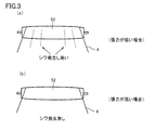
- the sandwiching pressure of the laminate (polarizing film and transparent film) by the bonding rolls 51, 52 is usually applied to both ends of the axis of one bonding roll 51. Since it is performed by pressing with a hydraulic pressure, pneumatic pressure, a screw or the like through a bearing or the like (arrow in FIG. 4B), the vicinity of the center of the bonding roll 51 is bent, and the laminate (polarizing film and transparent film) is formed. In some cases, the pressure was unevenly applied. When the pressure is applied unevenly, there are problems that bubbles are generated between the films in the obtained polarizing plate, and that the adhesion between the films is deteriorated.
- Such a phenomenon is a phenomenon that occurs when a high pressure needs to be applied to the laminate.
- an active energy ray curable resin is used as an adhesive, the viscosity is higher than when other polyvinyl alcohol-based resins or the like are used as an adhesive. Therefore, it is necessary to apply a high pressure to the laminate.
- JP 2004-245925 A JP 2009-134190 A JP 2011-95560 A
- the present invention has been made in order to solve the above-described problems, and a method for producing a polarizing plate and a method for producing a polarizing plate capable of uniformly pressing a laminate (polarizing film and transparent film) constituting the polarizing plate.
- An object is to provide an apparatus.
- the present invention is a method for producing a polarizing plate in which a transparent film is bonded to one side or both sides of a polarizing film, An adhesive coating step of applying an active energy ray-curable adhesive to one side or both sides of the transparent film or the polarizing film; At least one laminating roll in a state where the transparent film is sandwiched between a pair of laminating rolls rotating in the conveying direction, with a laminate in which the transparent film is laminated on one or both sides of the polarizing film via the adhesive.
- a bonding step of bonding the transparent film and the polarizing film By pressing in the direction of the other bonding roll, a bonding step of bonding the transparent film and the polarizing film; An active energy ray irradiation step of irradiating the laminate with an active energy ray to cure the adhesive; and
- One of the pair of bonding rolls is a method for producing a polarizing plate, which is a crown roll having a tapered outer peripheral shape whose diameter decreases from the center to the end.
- the bonding roll that is not the crown roll is preferably a flat roll having a substantially uniform diameter.
- the shape of the crown roll is preferably designed so that the distance between the crown roll and the flat roll is substantially uniform in the state where the pressing is performed in the bonding step.
- the ratio of the difference between the diameter of the center portion and the diameter of the end portion of the crown roll is preferably 0.002% or more with respect to the length of the crown roll.
- the tapered outer peripheral shape of the crown roll is an arc shape.
- the present invention is a polarizing plate manufacturing apparatus in which a transparent film is bonded to one side or both sides of a polarizing film, An adhesive coating device for applying an active energy ray-curable adhesive on one side or both sides of the transparent film or the polarizing film; A pair of the transparent film and the polarizing film are bonded together by sandwiching the transparent film while transporting a laminate in which the transparent film is laminated on one or both sides of the polarizing film via the adhesive.
- One of said pair of bonding rolls is also related to the manufacturing apparatus of a polarizing plate characterized by being a crown roll which has a taper-shaped outer periphery shape where a diameter becomes small from a center part to an edge part.
- the present invention it is possible to provide a polarizing plate manufacturing method and a polarizing plate manufacturing apparatus that can uniformly pressurize the laminate (polarizing film and transparent film) constituting the polarizing plate.
- the present invention it is possible to obtain a polarizing plate in which bubbles are generated between the films or adhesion between the films is suppressed. In addition, the occurrence of troubles in the manufacturing process due to the deterioration in the flow of conveyance is also suppressed.
- the polarizing film used in the polarizing plate of the present invention is obtained by adsorbing and orienting a dichroic dye on a uniaxially stretched polyvinyl alcohol resin film.
- the polyvinyl alcohol-based resin can be obtained by saponifying a polyvinyl acetate-based resin.
- Polyvinyl acetate resins include polyvinyl acetate, which is a homopolymer of vinyl acetate, and copolymers of vinyl acetate and other monomers copolymerizable therewith (for example, ethylene-vinyl acetate copolymer). Polymer).
- polyvinyl alcohol resins may be modified. For example, polyvinyl formal modified with aldehydes, polyvinyl acetal, polyvinyl butyral, and the like may be used.
- a film obtained by forming such a polyvinyl alcohol resin is used as an original film of a polarizing film.
- the method for forming the polyvinyl alcohol-based resin is not particularly limited, and can be formed by a conventionally known appropriate method.
- the film thickness of the raw film made of polyvinyl alcohol resin is not particularly limited, but is, for example, about 10 to 150 ⁇ m. Usually, it is supplied in the form of a roll, the thickness is in the range of 20 to 100 ⁇ m, preferably in the range of 30 to 80 ⁇ m, and the industrially practical width is in the range of 500 to 6000 mm.
- a polyolefin film or a polyester film such as a PET film may be used as a base material and a polyvinyl alcohol resin may be applied to both or one side thereof.
- polyvinyl alcohol-based films include “Vinylon VF-PS # 7500, manufactured by Kuraray” and “OPL film M-7500, manufactured by Nippon Gosei” (both have a thickness of 75 ⁇ m), “Vinylon VF-PS # 6000, Kuraray” "Made by vinylon VF-PE # 6000, made by Kuraray” (both original thickness is 60 ⁇ m), “made by vinylon VF-PE # 5000, made by Kuraray” (original thickness is 50 ⁇ m), “vinylon VF-PE # 3000, “Kuraray” (raw thickness is 30 ⁇ m).
- the polarizing film is usually a process of dyeing a polyvinyl alcohol resin film with a dichroic dye to adsorb the dichroic dye (dyeing process), and a polyvinyl alcohol resin film adsorbed with the dichroic dye is boric acid. It is manufactured through a step of treating with an aqueous solution (boric acid treatment step) and a step of washing with water after the treatment with the boric acid aqueous solution (water washing treatment step).
- the polyvinyl alcohol-based resin film is usually uniaxially stretched, but this uniaxial stretching may be performed before the dyeing treatment step or during the dyeing treatment step, It may be performed after the dyeing process.
- the uniaxial stretching may be performed before the boric acid treatment step or during the boric acid treatment step.
- uniaxial stretching can be performed in these plural stages.
- the uniaxial stretching may be performed uniaxially between rolls having different peripheral speeds, or may be performed uniaxially using a hot roll. Moreover, the dry-type extending
- the draw ratio is usually about 3 to 8 times.
- the dyeing of the polyvinyl alcohol-based resin film with the dichroic dye in the dyeing process is performed, for example, by immersing the polyvinyl alcohol-based resin film in an aqueous solution containing the dichroic dye.
- the dichroic dye for example, iodine, a dichroic dye or the like is used.
- dichroic dyes include C.I. I. Dichroic direct dyes composed of disazo compounds such as DIRECT RED 39, and dichroic direct dyes composed of compounds such as trisazo and tetrakisazo are included.
- the polyvinyl alcohol-type resin film performs the immersion process to water before a dyeing process.
- iodine When iodine is used as the dichroic dye, a method of dyeing a polyvinyl alcohol-based resin film in an aqueous solution containing iodine and potassium iodide is usually employed.
- the content of iodine in this aqueous solution is usually 0.01 to 1 part by weight per 100 parts by weight of water, and the content of potassium iodide is usually 0.5 to 20 parts by weight per 100 parts by weight of water.
- the temperature of the aqueous solution used for dyeing is usually 20 to 40 ° C.
- the immersion time (dyeing time) in this aqueous solution is usually 20 to 1800 seconds.
- a method of immersing and dyeing a polyvinyl alcohol-based resin film in an aqueous solution containing an aqueous dichroic dye is usually employed.
- the content of the dichroic dye in this aqueous solution usually, 1 ⁇ 10 -4 ⁇ 10 parts by weight per 100 parts by weight of water, preferably 1 ⁇ 10 -3 ⁇ 1 parts by weight, particularly preferably 1 ⁇ 10 - 3 to 1 ⁇ 10 ⁇ 2 parts by weight.
- This aqueous solution may contain an inorganic salt such as sodium sulfate as a dyeing assistant.
- the temperature of the dye aqueous solution used for dyeing is usually 20 to 80 ° C.
- the immersion time (dyeing time) in this aqueous solution is usually 10 to 1800 seconds. is there.
- the boric acid treatment step is performed by immersing a polyvinyl alcohol resin film dyed with a dichroic dye in a boric acid-containing aqueous solution.
- the amount of boric acid in the boric acid-containing aqueous solution is usually 2 to 15 parts by weight, preferably 5 to 12 parts by weight per 100 parts by weight of water.
- the boric acid-containing aqueous solution used in this boric acid treatment process preferably contains potassium iodide.
- the amount of potassium iodide in the boric acid-containing aqueous solution is usually 0.1 to 15 parts by weight, preferably 5 to 12 parts by weight, per 100 parts by weight of water.
- the immersion time in the boric acid-containing aqueous solution is usually 60 to 1200 seconds, preferably 150 to 600 seconds, and more preferably 200 to 400 seconds.
- the temperature of the boric acid-containing aqueous solution is usually 40 ° C. or higher, preferably 50 to 85 ° C., more preferably 55 to 80 ° C.
- the polyvinyl alcohol-based resin film after the boric acid treatment described above is washed with water, for example, by immersing it in water.
- the temperature of water in the water washing treatment is usually 4 to 40 ° C., and the immersion time is usually 1 to 120 seconds.
- a drying treatment is usually performed to obtain a polarizing film.
- the drying process is preferably performed using, for example, a hot air dryer or a far infrared heater.
- the temperature for the drying treatment is usually 30 to 100 ° C., preferably 50 to 80 ° C.
- the drying treatment time is usually 60 to 600 seconds, preferably 120 to 600 seconds.
- the polyvinyl alcohol resin film is subjected to uniaxial stretching, dyeing with a dichroic dye, boric acid treatment and water washing treatment to obtain a polarizing film.
- the thickness of this polarizing film is usually in the range of 3 to 50 ⁇ m.
- the film which has not only the said method but the polarizing function produced by another method is employ
- Transparent film In the present invention, a transparent film is bonded to one side or both sides of the polarizing film described above. When a transparent film is bonded on both surfaces of a polarizing film, each transparent film may be the same or a different type of film.
- Examples of the material constituting the transparent film include cycloolefin resins, cellulose acetate resins, polyethylene terephthalate, polyethylene naphthalate, polyester resins such as polybutylene terephthalate, polycarbonate resins, and polymethyl methacrylate (PMMA).
- Examples thereof include film materials that have been widely used in the art, such as acrylic resins and olefin resins such as polypropylene.
- the cycloolefin resin is a thermoplastic resin (also referred to as a thermoplastic cycloolefin resin) having a monomer unit made of a cyclic olefin (cycloolefin), such as norbornene or a polycyclic norbornene monomer.
- the cycloolefin-based resin may be a hydrogenated product of the above-mentioned cycloolefin ring-opening polymer or a ring-opening copolymer using two or more cycloolefins, and has a cycloolefin, a chain olefin, and a vinyl group.
- An addition polymer with an aromatic compound or the like may be used. Those having a polar group introduced are also effective.
- examples of the chain olefin include ethylene and propylene
- examples of the aromatic compound having a vinyl group include Examples include styrene, ⁇ -methylstyrene, and nuclear alkyl-substituted styrene.
- the monomer unit composed of cycloolefin may be 50 mol% or less (preferably 15 to 50 mol%).
- the amount of the monomer unit composed of cycloolefin can be made relatively small as described above.
- the unit of monomer composed of a chain olefin is usually 5 to 80 mol%
- the unit of monomer composed of an aromatic compound having a vinyl group is usually 5 to 80 mol%.
- Cycloolefin-based resins may be commercially available products such as Topas (manufactured by Ticona), Arton (manufactured by JSR), ZEONOR (manufactured by Nippon Zeon), ZEONEX (manufactured by Nippon Zeon ( Co., Ltd.), Apel (manufactured by Mitsui Chemicals, Inc.), Oxis (OXIS) (manufactured by Okura Kogyo Co., Ltd.) and the like can be suitably used.
- a known method such as a solvent casting method or a melt extrusion method is appropriately used.
- cycloolefin resin films such as Essina (manufactured by Sekisui Chemical Co., Ltd.), SCA40 (manufactured by Sekisui Chemical Co., Ltd.), Zeonoa Film (manufactured by Optes Co., Ltd.), etc. You may use goods.
- the cycloolefin resin film may be uniaxially stretched or biaxially stretched.
- Stretching is usually performed continuously while unwinding a film roll, and in a heating furnace, the roll traveling direction (film longitudinal direction), the direction perpendicular to the traveling direction (film width direction), or both Stretched.
- the temperature of the heating furnace a range from the vicinity of the glass transition temperature of the cycloolefin resin to the glass transition temperature + 100 ° C. is usually employed.
- the stretching ratio is usually 1.1 to 6 times, preferably 1.1 to 3.5 times.
- the cycloolefin-based resin film When the cycloolefin-based resin film is in a roll-wound state, the films tend to adhere to each other and easily cause blocking. Therefore, the cycloolefin-based resin film is usually rolled after the protective film is bonded.
- the surface to be bonded to the polarizing film is subjected to surface treatment such as plasma treatment, corona treatment, ultraviolet irradiation treatment, flame (flame) treatment, and saponification treatment. Is preferred.
- plasma treatment that can be carried out relatively easily, particularly atmospheric pressure plasma treatment, and corona treatment are preferable.
- the cellulose acetate-based resin is a cellulose part or a completely esterified product, and examples thereof include a film made of cellulose acetate ester, propionate ester, butyrate ester, and mixed ester thereof. More specifically, a triacetyl cellulose film, a diacetyl cellulose film, a cellulose acetate propionate film, a cellulose acetate butyrate film, and the like can be given.
- a cellulose ester resin film As such a cellulose ester resin film, an appropriate commercially available product, for example, Fujitac TD80 (manufactured by Fuji Film Co., Ltd.), Fujitac TD80UF (manufactured by Fuji Film Co., Ltd.), Fujitac TD80UZ (manufactured by Fuji Film Co., Ltd.) KC8UX2M (manufactured by Konica Minolta Opto), KC8UY (manufactured by Konica Minolta Opto) Fujitac TD60UL (manufactured by Fuji Film), KC4UYW (manufactured by Konica Minolta Opto), KC6UAW (Konica Minolta Opto) Etc.) can be used preferably.
- Fujitac TD80 manufactured by Fuji Film Co., Ltd.
- Fujitac TD80UF manufactured by Fuji Film Co., Ltd.
- a cellulose acetate-based resin film imparted with retardation characteristics is also preferably used.
- Commercially available cellulose acetate resin films with such retardation characteristics include WV BZ 438 (Fuji Film Co., Ltd.), KC4FR-1 (Konica Minolta Opto Co., Ltd.), and KC4CR-1 (Konica Minolta). Opt Co., Ltd.), KC4AR-1 (Konica Minolta Opto Co., Ltd.) and the like.
- Cellulose acetate is also called acetyl cellulose or cellulose acetate.
- the moisture content during the production of the polarizing plate is preferably closer to the equilibrium moisture content in the storage environment of the polarizing plate, for example, a clean room production line or a roll storage warehouse, and depends on the configuration of the laminated film. About 5%, more preferably 2.5% to 3.0%.
- the numerical value of the moisture content of this polarizing plate was measured by the dry weight method and is a change in weight after 105 ° C./120 minutes.
- the thickness of the transparent film used in the polarizing plate of the present invention is preferably thin, but if it is too thin, the strength is lowered and the workability is poor. On the other hand, when it is too thick, problems such as a decrease in transparency and a longer curing time after lamination occur. Therefore, a suitable thickness of the transparent film is, for example, 5 to 200 ⁇ m, preferably 10 to 150 ⁇ m, more preferably 10 to 100 ⁇ m.
- the polarizing film and / or the transparent film may be subjected to corona treatment, flame treatment, plasma treatment, ultraviolet treatment, primer coating treatment, saponification treatment, etc.
- a surface modification treatment may be performed.
- the transparent film may be subjected to surface treatments such as anti-glare treatment, anti-reflection treatment, hard coat treatment, antistatic treatment, and antifouling treatment individually or in combination of two or more.
- the transparent film and / or the transparent film surface protective layer may contain a UV absorber such as a benzophenone compound or a benzotriazole compound, or a plasticizer such as a phenyl phosphate compound or a phthalate compound.
- optical functions such as functions as a retardation film, function as a brightness enhancement film, function as a reflection film, function as a transflective film, function as a diffusion film, function as an optical compensation film, etc.
- a function for example, by laminating an optical functional film such as a retardation film, a brightness enhancement film, a reflection film, a transflective film, a diffusion film, and an optical compensation film on the surface of the transparent film, such a function is achieved.
- the transparent film itself can be given such a function.
- the transparent film may have a plurality of functions such as a diffusion film having the function of a brightness enhancement film.
- the above-mentioned transparent film is subjected to a stretching process described in Japanese Patent No. 2841377, Japanese Patent No. 3094113, or the like, or a process described in Japanese Patent No. 3168850 can be used as a retardation film.
- the function of can be provided.
- the retardation characteristics of the retardation film can be appropriately selected, for example, such that the front retardation value is in the range of 5 to 100 nm and the thickness direction retardation value is in the range of 40 to 300 nm.
- two or more layers having different central wavelengths of selective reflection are formed in the transparent film by forming micropores by a method as described in Japanese Patent Application Laid-Open Nos. 2002-169025 and 2003-29030. By superimposing these cholesteric liquid crystal layers, a function as a brightness enhancement film can be imparted.
- a function as a reflective film or a transflective film can be imparted.
- a function as a diffusion film can be imparted.
- the function as an optical compensation film can be provided by coating and aligning liquid crystalline compounds, such as a discotic liquid crystalline compound, on said transparent film.
- you may make the transparent film contain the compound which expresses retardation.
- various optical functional films may be directly bonded to the polarizing film using an appropriate adhesive.
- optical functional films examples include brightness enhancement films such as DBEF (manufactured by 3M, available from Sumitomo 3M Co., Ltd. in Japan), and viewing angle improvements such as WV film (manufactured by Fuji Film Co., Ltd.).
- Film, Arton Film (manufactured by JSR Corporation), Zeonoor Film (manufactured by Optes Corporation), Essina (manufactured by Sekisui Chemical Co., Ltd.), VA-TAC (manufactured by Comic Minolta Opto Corporation), Sumikalite (Sumitomo) (Chemical Co., Ltd.) etc. can be mentioned.
- the polarizing film and the transparent film are bonded via an active energy ray curable adhesive.
- the active energy ray-curable adhesive include an adhesive made of an epoxy resin composition containing an epoxy resin that is cured by irradiation with active energy rays from the viewpoint of weather resistance, refractive index, cationic polymerization, and the like. .
- the present invention is not limited to this, and various active energy ray-curable adhesives (organic solvent adhesives, hot melt adhesives, solventless adhesives) that have been used in the manufacture of polarizing plates. Etc.) can be adopted.
- the active energy ray-curable adhesive include an adhesive made of an acrylic resin composition such as acrylamide, acrylate, urethane acrylate, and epoxy acrylate.
- An epoxy resin means a compound having two or more epoxy groups in a molecule.
- the epoxy resin contained in the curable epoxy resin composition that is an adhesive is an epoxy resin that does not contain an aromatic ring in the molecule (see, for example, Patent Document 1). It is preferable that Examples of such epoxy resins include hydrogenated epoxy resins, alicyclic epoxy resins, aliphatic epoxy resins, and the like.
- the hydrogenated epoxy resin is obtained by a method of glycidyl etherifying a nuclear hydrogenated polyhydroxy compound obtained by selectively subjecting a polyhydroxy compound, which is a raw material of an aromatic epoxy resin, to a nuclear hydrogenation reaction under pressure in the presence of a catalyst. Obtainable.
- aromatic epoxy resins include bisphenol-type epoxy resins such as bisphenol A diglycidyl ether, bisphenol F diglycidyl ether, and bisphenol S diglycidyl ether; phenol novolac epoxy resins, cresol novolac epoxy resins, and hydroxy Examples include novolak-type epoxy resins such as benzaldehyde phenol novolac epoxy resins; glycidyl ethers of tetrahydroxyphenylmethane, glycidyl ethers of tetrahydroxybenzophenone, and polyfunctional epoxy resins such as epoxidized polyvinylphenol.
- hydrogenated epoxy resins hydrogenated bisphenol A glycidyl ether is preferred.
- the alicyclic epoxy resin means an epoxy resin having at least one epoxy group bonded to the alicyclic ring in the molecule.
- the “epoxy group bonded to an alicyclic ring” means a bridged oxygen atom —O— in the structure represented by the following formula. In the following formula, m is an integer of 2 to 5.
- a compound in which a group in the form of removing one or more hydrogen atoms in (CH 2 ) m in the above formula is bonded to another chemical structure can be an alicyclic epoxy resin.
- One or more hydrogen atoms in (CH 2 ) m may be appropriately substituted with a linear alkyl group such as a methyl group or an ethyl group.
- the alicyclic epoxy resin used preferably below is specifically illustrated, it is not limited to these compounds.
- R 1 and R 2 each independently represent a hydrogen atom or a linear alkyl group having 1 to 5 carbon atoms).
- R 3 and R 4 each independently represent a hydrogen atom or a linear alkyl group having 1 to 5 carbon atoms, and n represents an integer of 2 to 20).
- R 5 and R 6 each independently represent a hydrogen atom or a linear alkyl group having 1 to 5 carbon atoms, and p represents an integer of 2 to 20).
- R 7 and R 8 independently of each other represent a hydrogen atom or a linear alkyl group having 1 to 5 carbon atoms, and q represents an integer of 2 to 10).
- R 9 and R 10 independently of each other represent a hydrogen atom or a linear alkyl group having 1 to 5 carbon atoms, and r represents an integer of 2 to 20).
- R 11 and R 12 each independently represent a hydrogen atom or a linear alkyl group having 1 to 5 carbon atoms).
- R 13 and R 14 each independently represent a hydrogen atom or a linear alkyl group having 1 to 5 carbon atoms).
- R 16 and R 17 each independently represent a hydrogen atom or a linear alkyl group having 1 to 5 carbon atoms).
- R 18 represents a hydrogen atom or a linear alkyl group having 1 to 5 carbon atoms.
- the following alicyclic epoxy resins are commercially available or their analogs, and are more preferably used because they are relatively easy to obtain.
- examples of the aliphatic epoxy resin include polyglycidyl ethers of aliphatic polyhydric alcohols or alkylene oxide adducts thereof. More specifically, 1,4-butanediol diglycidyl ether; 1,6-hexanediol diglycidyl ether; glycerin triglycidyl ether; trimethylolpropane triglycidyl ether; polyethylene glycol diglycidyl ether; propylene Diglycidyl ether of glycol; Polyether of polyether polyol obtained by adding one or more alkylene oxides (ethylene oxide or propylene oxide) to aliphatic polyhydric alcohols such as ethylene glycol, propylene glycol, and glycerin A glycidyl ether etc. are mentioned.
- the epoxy resin which comprises the adhesive agent which consists of an epoxy-type resin composition may be used individually by 1 type, and may use 2 or more types together.
- the epoxy equivalent of the epoxy resin used in this composition is usually in the range of 30 to 3,000 g / equivalent, preferably 50 to 1,500 g / equivalent.
- the epoxy equivalent is less than 30 g / equivalent, the flexibility of the composite polarizing plate after curing may be reduced, or the adhesive strength may be reduced.
- it exceeds 3,000 g / equivalent the compatibility with other components contained in the adhesive may be lowered.
- cationic polymerization is preferably used as a curing reaction of the epoxy resin from the viewpoint of reactivity. Therefore, it is preferable to mix
- the cationic polymerization initiator generates a cationic species or a Lewis acid by irradiation with active energy rays such as visible light, ultraviolet rays, X-rays, and electron beams, and initiates an epoxy group polymerization reaction.
- a cationic polymerization initiator that generates a cationic species or a Lewis acid by irradiation of active energy rays and initiates a polymerization reaction of an epoxy group is referred to as a “photo cationic polymerization initiator”.
- the method of curing the adhesive by irradiating with active energy rays using a cationic photopolymerization initiator enables curing at room temperature, reducing the need to consider the distortion due to heat resistance or expansion of the polarizing film, and between the films Is advantageous in that it can be bonded well.
- the photocationic polymerization initiator acts catalytically by light, it is excellent in storage stability and workability even when mixed with an epoxy resin.
- photocationic polymerization initiator examples include aromatic diazonium salts; onium salts such as aromatic iodonium salts and aromatic sulfonium salts; iron-allene complexes and the like.
- aromatic diazonium salt examples include benzenediazonium hexafluoroantimonate, benzenediazonium hexafluorophosphate, benzenediazonium hexafluoroborate, and the like.
- aromatic iodonium salt examples include diphenyliodonium tetrakis (pentafluorophenyl) borate, diphenyliodonium hexafluorophosphate, diphenyliodonium hexafluoroantimonate, di (4-nonylphenyl) iodonium hexafluorophosphate, and the like.
- aromatic sulfonium salt examples include triphenylsulfonium hexafluorophosphate, triphenylsulfonium hexafluoroantimonate, triphenylsulfonium tetrakis (pentafluorophenyl) borate, 4,4′-bis (diphenylsulfonio) diphenyl sulfide bis ( Hexafluorophosphate), 4,4′-bis [di ( ⁇ -hydroxyethoxy) phenylsulfonio] diphenyl sulfide, bis (hexafluoroantimonate), 4,4′-bis [di ( ⁇ -hydroxyethoxy) phenylsulfonio ] Diphenyl sulfide bis (hexafluorophosphate), 7- [di (p-toluyl) sulfonio] -2-isopropylthioxanthone hexafluor
- iron-allene complex examples include xylene-cyclopentadienyl iron (II) hexafluoroantimonate, cumene-cyclopentadienyl iron (II) hexafluorophosphate, xylene-cyclopentadienyl iron (II). -Tris (trifluoromethylsulfonyl) methanide and the like.
- photocationic polymerization initiators can be easily obtained.
- “Kayarad PCI-220” and “Kayarad PCI-620” Nippon Kayaku Co., Ltd. )
- “UVI-6990” manufactured by Union Carbide
- “Adekaoptomer SP-150” and “Adekaoptomer SP-170” manufactured by ADEKA Corporation
- “CI-5102”, “ “CIT-1370”, “CIT-1682”, “CIP-1866S”, “CIP-2048S” and “CIP-2064S” aboveve, Nippon Soda Co., Ltd.
- the photocationic polymerization initiator may be used alone or in combination of two or more.
- aromatic sulfonium salts are preferably used because they have ultraviolet absorption characteristics even in a wavelength region of 300 nm or more, and thus can provide a cured product having excellent curability and good mechanical strength and adhesive strength.
- the amount of the cationic photopolymerization initiator is usually 0.5 to 20 parts by weight, preferably 1 part by weight or more, and preferably 15 parts by weight or less based on 100 parts by weight of the epoxy resin.
- the blending amount of the cationic photopolymerization initiator is less than 0.5 parts by weight with respect to 100 parts by weight of the epoxy resin, curing becomes insufficient, and mechanical strength and adhesive strength tend to decrease.
- the compounding quantity of a photocationic polymerization initiator exceeds 20 weight part with respect to 100 weight part of epoxy resins, the hygroscopic property of hardened
- the curable epoxy resin composition may further contain a photosensitizer as necessary.
- a photosensitizer By using a photosensitizer, the reactivity of cationic polymerization is improved, and the mechanical strength and adhesive strength of the cured product can be improved.
- the photosensitizer include carbonyl compounds, organic sulfur compounds, persulfides, redox compounds, azo and diazo compounds, halogen compounds, and photoreductive dyes.
- photosensitizers include, for example, benzoin derivatives such as benzoin methyl ether, benzoin isopropyl ether, and ⁇ , ⁇ -dimethoxy- ⁇ -phenylacetophenone; benzophenone, 2,4-dichlorobenzophenone, o Benzophenone derivatives such as methyl benzoylbenzoate, 4,4′-bis (dimethylamino) benzophenone, and 4,4′-bis (diethylamino) benzophenone; thioxanthone derivatives such as 2-chlorothioxanthone and 2-isopropylthioxanthone; 2 Anthraquinone derivatives such as chloroanthraquinone and 2-methylanthraquinone; acridone derivatives such as N-methylacridone and N-butylacridone; other ⁇ , ⁇ -diethoxyacetophenone, ben Examples include zil, fluorenone
- the epoxy resin contained in the adhesive is cured by photocationic polymerization, but may be cured by both photocationic polymerization and thermal cationic polymerization. In the latter case, it is preferable to use a photocationic polymerization initiator and a thermal cationic polymerization initiator in combination.
- thermal cationic polymerization initiator examples include benzylsulfonium salt, thiophenium salt, thiolanium salt, benzylammonium, pyridinium salt, hydrazinium salt, carboxylic acid ester, sulfonic acid ester, and amine imide.
- thermal cationic polymerization initiators can be easily obtained as commercial products. For example, “Adeka Opton CP77” and “Adeka Opton CP66” (manufactured by ADEKA Corporation), “CI” are available under the trade names.
- the active energy ray-curable adhesive may further contain a compound that promotes cationic polymerization, such as oxetanes and polyols.
- Oxetanes are compounds having a 4-membered ring ether in the molecule, such as 3-ethyl-3-hydroxymethyloxetane, 1,4-bis [(3-ethyl-3-oxetanyl) methoxymethyl] benzene, 3 -Ethyl-3- (phenoxymethyl) oxetane, di [(3-ethyl-3-oxetanyl) methyl] ether, 3-ethyl-3- (2-ethylhexyloxymethyl) oxetane, phenol novolac oxetane and the like. These oxetanes can be easily obtained as commercial products.
- polyols those having no acidic groups other than phenolic hydroxyl groups are preferable.
- polyol compounds having no functional groups other than hydroxyl groups polyester polyol compounds, polycaprolactone polyol compounds, polyol compounds having phenolic hydroxyl groups, polycarbonates A polyol etc. can be mentioned.
- the molecular weight of these polyols is usually 48 or more, preferably 62 or more, more preferably 100 or more, and preferably 1,000 or less.
- These polyols are usually contained in the curable epoxy resin composition in a proportion of 50% by weight or less, preferably 30% by weight or less.
- Active energy ray-curable adhesives include ion trapping agents, antioxidants, chain transfer agents, tackifiers, thermoplastic resins, fillers, flow regulators, leveling agents, plasticizers, antifoaming agents, etc. Additives can be blended.
- the ion trapping agent include powdered bismuth-based, antimony-based, magnesium-based, aluminum-based, calcium-based, titanium-based, and mixed inorganic compounds.
- the antioxidant is a hindered phenol-based antioxidant. Etc.
- Active energy ray-curable adhesives can be used as solventless adhesives that are substantially free of solvent components, but each coating method has an optimum viscosity range, A solvent may be included. It is preferable to use a solvent that dissolves the epoxy resin composition and the like well without degrading the optical performance of the polarizing film.
- a solvent that dissolves the epoxy resin composition and the like well without degrading the optical performance of the polarizing film.
- organic solvents such as The viscosity of the active energy ray-curable adhesive used in the present invention is, for example, in the range of about 5 to 1000 mPa ⁇ s, preferably 10 to 200 mPa ⁇ s, and more preferably 20 to 100 mPa ⁇ s.
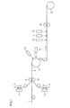
- FIG. 1 is a schematic view showing an embodiment of a polarizing plate production apparatus of the present invention.
- the polarizing plate manufacturing apparatus 30 shown in FIG. 1 bonds the adhesive coating apparatuses 11 and 12 for applying an adhesive to one side of the transparent films 2 and 3, and the transparent films 2 and 3 and the polarizing film 1.
- Bonding rolls (nip rolls) 51 and 52 for obtaining the laminate 4 the roll 13 for bringing the transparent films 2 and 3 and the polarizing film 1 into close contact with each other in the laminate 4, and the outer peripheral surface of the roll 13
- First active energy beam irradiating devices 14 and 15 installed at opposite positions, second and subsequent active energy beam irradiating devices 16 to 18 installed further downstream in the transport direction, and a transport nip roll 19 Are provided in order along the transport direction.
- an active energy ray-curable adhesive is applied to one side of the transparent films 2 and 3 that are continuously drawn out from a rolled state by an adhesive application device 11 or 12 (adhesive coating). Construction process).
- coated on both surfaces of the polarizing film 1 continuously drawn out from the state wound by roll shape via an adhesive agent is conveyed.
- the polarizing film 1 and the transparent films 2 and 3 are pressed by pressing at least one bonding roll in the direction of the other bonding roll while being sandwiched between a pair of bonding rolls 51 and 52 rotating in the direction. Are pasted together to form the laminate 4 (a pasting step).
- the active energy rays are irradiated from the first active energy ray irradiating devices 14, 15 toward the outer peripheral surface of the roll 13 to be bonded.
- the agent is polymerized and cured (active energy ray irradiation step).
- the second and subsequent active energy ray irradiation devices 16 to 18 arranged on the downstream side in the transport direction are devices for completely polymerizing and curing the adhesive, and can be added or omitted as necessary.
- the laminate 4 passes through the conveyance nip roll 19 and is wound around the winding roll 20 as a polarizing plate.
- the method for applying the adhesive to the transparent films 2 and 3 is not particularly limited, and various coating methods such as a doctor blade, a wire bar, a die coater, a comma coater, and a gravure coater can be used. Of these, taking into consideration the thin film coating, the degree of freedom of the pass line, the wideness, etc., gravure rolls are preferable as the adhesive coating apparatuses 11 and 12. Examples of commercially available coating apparatuses include MCD (microchamber doctor) manufactured by Fuji Machine Co., Ltd.
- the thickness of the applied adhesive is preferably about 0.1 to 10 ⁇ m, more preferably 0.2 ⁇ m to 4 ⁇ m.
- the coating thickness of the adhesive is adjusted by the draw ratio, which is the speed ratio of the gravure roll to the line speed of the transparent film. Generally, by adjusting the draw ratio (gravure roll speed / line speed) to 0.5 to 10, the coating thickness of the adhesive can be adjusted to about 0.1 to 10 ⁇ m.
- the line speed of the transparent films 2 and 3 is set to 10 to 100 m / min
- the gravure roll is rotated in the direction opposite to the conveying direction of the transparent films 2 and 3
- the speed of the gravure roll is set to 5 to 1000 m / min.
- the adhesive is usually at a predetermined temperature ⁇ 5 ° C. within the range of 15 to 40 ° C. (for example, 30 ° C. ⁇ 5 ° C. when the predetermined temperature is 30 ° C.), preferably ⁇ 3 ° C., more preferably It is applied in an environment adjusted to ⁇ 1 ° C.
- the transparent films 2 and 3 to which the adhesive is applied by the above-described steps are laminated on both surfaces of the polarizing film 1 that is continuously drawn out from the state wound in a roll shape.
- the bonding roll 51 is pressed in the direction of the bonding roll 52 so that the polarizing film 1 and the transparent film are pressed. 2 and 3 are bonded together to form a laminate 4.
- the polarizing film is so formed that the conveying direction of the polarizing film forms an angle within a range of ⁇ 3 °, more preferably within a range of ⁇ 1 ° with respect to a plane perpendicular to the pressing direction of the bonding roll. Is conveyed between the bonding rolls. Particularly preferably, the polarizing film is conveyed between the bonding rolls so that the conveying direction of the polarizing film overlaps with a surface perpendicular to the pressing direction of the bonding roll. By doing in this way, a polarizing film and a transparent film will contact before the bonding roll, and a bubble will not generate
- the adhesive is uniformly applied to one side of the transparent films 2, 3, and the polarizing film 1 is overlapped on the surface of the transparent films 2, 3 applied with the bonding rolls 51, 52.
- the adhesive agent is apply
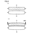
- the present invention is characterized in that one of the pair of bonding rolls 51 and 52 is a crown roll having a tapered outer peripheral shape whose diameter decreases from the center to the end. That is, the radius of the center portion of the crown roll is larger than the radius of the end portion.
- the non-crown roll bonding roll is a flat roll having a substantially uniform diameter.
- the shape of the crown roll is preferably designed so that the distance between the crown roll and the flat roll is substantially uniform in a state where pressing is performed in the bonding step.
- interval of a crown roll and a flat roll is a space
- the crown roll and the flat roll are arranged so that the axis of the crown roll and the axis of the flat roll are parallel when no pressure is applied.
- the ratio of the difference between the diameter of the center portion and the diameter of the end portion of the crown roll is preferably 0.002% or more with respect to the length of the crown roll (length in the axial direction). More preferably, it is 0.005 to 0.040%.
- the shape of the crown roll can be designed so that the distance between the crown roll and the flat roll in a state where pressing is performed in the bonding step is uniform.
- the tapered outer peripheral shape of the crown roll is preferably an arc shape.
- the taper-shaped outer peripheral shape of the crown roll being arc-shaped means that the cross section of the crown roll on the surface including the axis of the tapered outer peripheral shape is an arc.
- the flat roll When the shaft member of the flat roll is pressed in the bonding process, the flat roll often bends so that the outer peripheral shape becomes an arc shape, and the outer peripheral shape of the opposing crown roll has a radius of curvature similar to that. It is because it can make the space
- the diameter of the laminating roll is not particularly limited, but the diameter of the flat roll is preferably 50 to 400 mm.
- the diameter of the end portion of the crown roll is preferably 50 to 400 mm.
- the diameter of each of a pair of bonding roll may be the same, and may differ.
- the width of the bonding roll is preferably 300 to 3000 mm.
- the pressure applied to the laminate by the pressing is not particularly limited, but when a metal roll and a rubber roll are used, the instantaneous pressure in a two-sheet type press case (for ultra-low pressure) made of Fuji Film is 0.5 to
- the pressure is preferably 3.0 MPa, more preferably 0.7 to 2.3 MPa.
- the external force of the press with respect to this bonding roll is normally applied via a bearing etc. with respect to the both ends of the axis
- the material of the bonding roll includes metal and rubber. It is preferable that one of the pair of bonding rolls is a metal roll and the other is a rubber roll. Furthermore, it is more preferable that the flat roll is made of metal and the crown roll is made of rubber.
- the upper bonding roll to be pressed is usually made of rubber, and the lower bonding roll is made of metal.
- the lower laminating roll is made of metal, and the lower laminating roll is not deformed when pressed because the lower laminating roll is made of metal because the drive motor is attached to the lower laminating roll. It is because it is easy to maintain the peripheral speed of a bonding roll constant.
- the pressed (upper) bonding roll is made of metal, and the other (lower) bonding roll is made of rubber. Is preferred.
- the base material of the metal roll various known materials can be used, preferably stainless steel, and more preferably SUS304 (stainless steel containing 18% Cr and 8% Ni).
- the surface of the metal roll is preferably subjected to chrome plating.
- the material of the rubber roll is not particularly limited, and examples thereof include NBR (nitrile rubber), Titan, urethane, silicon, EPDM (ethylene-propylene-diene rubber), and preferably NBR, Titan, and urethane.
- the hardness of the rubber roll is not particularly limited, but is usually 60 to 100 °, preferably 85 to 95 °.
- the hardness of a rubber roll can be measured with the hardness meter based on JISK6253.
- a rubber hardness meter “Type-A” manufactured by Asuka Corporation is used. Specifically, the resistance of the surface of the rubber roll when the surface is pressed with a stick or the like is measured with a hardness meter.
- a crown roll When a crown roll is used as the bonding roll, it is preferable to maintain a high tension related to the laminate, for example, 300 to 800 N / m. In this case, as shown in FIG. 3B, when the laminate 4 conveyed from the crown roll 52 is not wrinkled, and the tension applied to the laminate 4 is lower than this, the laminate 4 is shown in FIG. Thus, wrinkles are likely to occur in the laminate 4 conveyed from the crown roll 52.
- the peripheral speed of the bonding roll (1st bonding roll) installed in the surface side bonded to the liquid crystal panel of the laminated body 4 is the peripheral speed of the opposite bonding roll (2nd bonding roll). Is faster. Thereby, it is possible to give the obtained polarizing plate a curl (positive curl) in which the surface bonded to the liquid crystal panel becomes convex and the opposite surface becomes concave.
- the obtained polarizing plate is curled (reverse curl) so that the surface to be bonded to the liquid crystal panel is concave and the opposite surface is convex, the polarizing plate is bonded to the liquid crystal cell.
- the ratio of the peripheral speeds of the first laminating roll is more preferably 1.0050 to 1.0200.
- the peripheral speed of the first laminating roll is faster than this range, the curl amount of the positive curl becomes too large, causing problems such as entrapment of bubbles at the end when laminating the polarizing plate to the liquid crystal cell. This is because, when placed in a harsh environment, the positive curl is further promoted and the end of the polarizing plate may be peeled off from the liquid crystal cell.
- the roll 13 constitutes a convex curved surface whose outer peripheral surface is mirror-finished, and the laminate 4 is conveyed while closely contacting the surface, and the adhesive is polymerized and cured by the active energy ray irradiation devices 14 and 15 in the process. .
- the diameter of the roll 13 is not particularly limited when the adhesive is polymerized and cured and the laminate 4 is sufficiently adhered.
- the laminated body 4 in which the adhesive is in an uncured state is preferably irradiated with active energy rays so that the cumulative amount of light while passing through the roll 13 is 10 mJ / cm 2 or more.
- the roll 13 may be driven or rotated according to the movement of the line of the laminate 4 or may be fixed so that the laminate 4 slides on the surface.
- the roll 13 may act as a cooling roll for dissipating heat generated in the laminate 4 at the time of polymerization and curing by irradiation with active energy rays.
- the surface temperature of the cooling roll is preferably set to 4 to 30 ° C.
- the light source used for polymerizing and curing the adhesive by irradiation with active energy rays is not particularly limited, but is preferably a light source having an emission distribution at a wavelength of 400 nm or less.
- Examples of such a light source include a low pressure mercury lamp, a medium pressure mercury lamp, a high pressure mercury lamp, an ultrahigh pressure mercury lamp, a chemical lamp, a black light lamp, a microwave excitation mercury lamp, and a metal halide lamp.
- the light irradiation intensity to the active energy ray-curable adhesive is determined for each composition of the adhesive and is not particularly limited, but is preferably 10 to 5000 mW / cm 2 .
- the reaction time becomes too long, and when it exceeds 5000 mW / cm 2 , adhesion occurs due to heat radiated from the lamp and heat generated during polymerization of the composition.
- yellowing of the epoxy resin composition as a constituent material of the agent or deterioration of the polarizing film may occur.
- the irradiation intensity is preferably an intensity in a wavelength region effective for activation of the photocationic polymerization initiator, more preferably an intensity in a wavelength region of a wavelength of 400 nm or less, and further preferably a wavelength region of a wavelength of 280 to 320 nm. Strength.
- the irradiation time of the active energy ray to the active energy ray-curable adhesive is controlled for each composition to be cured and is not particularly limited, but the integrated light amount expressed as the product of the irradiation intensity and the irradiation time is It is preferably set to 55 mJ / cm 2 or more, preferably 55 to 5,000 mJ / cm 2 .
- the accumulated light amount to the adhesive is less than 55 mJ / cm 2 , the generation of active species derived from the initiator is not sufficient, the adhesive is not sufficiently cured, and both ends of the polarizing plate are wavy. Talmi defects may occur.
- the integrated light quantity exceeds 5,000 mJ / cm 2 , the irradiation time becomes very long, which is disadvantageous for improving productivity.
- the integrated light amount in which wavelength region (UVA (320 to 390 nm), UVB (280 to 320 nm), etc.) is required differs depending on the combination of the film to be used and the type of adhesive.
- the laminate is irradiated with active energy rays to polymerize and cure the adhesive, but polymerization curing by heating may be used in combination.
- the irradiation time is 0.1 while applying a tension of 100 to 800 N / m in the longitudinal direction (transport direction) to the laminate 4. It is preferable that the laminate 4 is conveyed at a line speed that is at least 2 seconds. Moreover, it is preferable that the irradiation intensity
- the active energy ray irradiation devices 16, 17, and 18 after the second are further provided, and the active energy rays are additionally irradiated. It is preferable to accelerate the curing of the adhesive of the laminate 4. It is preferable that the integrated light quantity in all these steps is set to 55 mJ / cm 2 or more, preferably 55 to 5,000 mJ / cm 2 . As described above, in the step of irradiating the active energy ray, the irradiation of the active energy ray is preferably performed in a plurality of times.
- the ratio at which the active energy ray-curable resin is cured, that is, the reaction rate is preferably 90% or more, more preferably 95% or more.
- the tension for winding the laminate (polarizing plate) 4 is not particularly limited, but is preferably in the range of 30 to 150 N / cm 2 , and more preferably in the range of 30 to 120 N / cm 2 . If the tension for winding the laminate 4 is less than 30 N / cm 2, at the time of transporting the rolled long, and because there is a risk that winding deviation occurs, is greater than 150 N / cm 2 is This is because the tightness of winding is strong and there is a tendency to cause tarmi.
- the length of the polarizing plate wound around the core is not particularly limited, but is preferably 100 to 4000 m or less.
- the diameter of the cylindrical core is preferably 6 to 12 inches.
- the diameter of the core is preferably as large as possible, and more preferably 11 inches, 12 inches, etc., but if it is too large, it tends to be difficult to transport and store.
- the material of the cylindrical core is not particularly limited as long as it can be used in a clean room and does not easily generate dust, and can secure an appropriate strength so that a wide-width polarizing plate can be wound.
- FRP glass fiber reinforced plastic
- Etc. can be selected.
- Example 1 (Preparation of polarizing film)
- a polyvinyl alcohol raw film a long polyvinyl alcohol film “Vinylon VF-PS # 7500 (manufactured by Kuraray)” having a polymerization degree of 2400, a saponification degree of 99.9 mol%, a thickness of 75 ⁇ m, and a width of 3000 mm was used. Stretching was performed with a difference in peripheral speed between the driving nip rolls before and after the treatment tank.
- the film was sufficiently swollen by immersing it in a swelling tank containing pure water at 30 ° C. for 80 seconds while keeping the tension state of the film so that the raw film did not loosen.
- the inlet / outlet roll speed ratio accompanying the swelling in the swelling tank was 1.2.
- After draining with a nip roll it was immersed in a water immersion tank containing 30 ° C. pure water for 160 seconds.
- the draw ratio in the machine direction in this tank was 1.09 times.
- uniaxial stretching was performed at a draw ratio of about 1.5 times while being immersed in a dyeing tank containing an aqueous solution of iodine / potassium iodide / water (weight ratio: 0.02 / 2.0 / 100). . Thereafter, the film was immersed in a boric acid bath containing an aqueous solution of potassium iodide / boric acid / water (weight ratio: 12 / 3.7 / 100) at 55.5 ° C. for 130 seconds, and the total draw ratio from the original fabric was uniaxially stretched until 5.7. Then, it was immersed in a boric acid bath containing an aqueous solution composed of potassium iodide / boric acid / water (weight ratio: 9 / 2.4 / 100) at 40 ° C. for 60 seconds.
- a cycloolefin resin film “ZEONOR” manufactured by ZEONOR
- a triacetyl cellulose film “KC8UX2MW” manufactured by Konica Minolta having a thickness of 80 ⁇ m were prepared.
- an epoxy resin composition including cationic polymerization initiator “KR series” (ADEKA), which is an ultraviolet curable adhesive, on one side of the above-mentioned cycloolefin resin film “ZEONOR” having a thickness of 75 ⁇ m.
- ADEKA epoxy resin composition (including cationic polymerization initiator) “KR series” (manufactured by ADEKA), which is an ultraviolet curable adhesive, is adhered to one side of the 80 ⁇ m thick triacetyl cellulose film “KC8UX2MW”. Coating was performed using an agent coating apparatus.
- the line speed of the polarizing film laminate in the adhesive coating apparatus is set to 25 m / min, the gravure roll is rotated in the direction opposite to the conveying direction of the laminated material, and a cycloolefin resin film “ZEONOR (ZEONOR) having a thickness of 75 ⁇ m
- the thickness of the adhesive layer on “)” was about 3.5 ⁇ m, and the thickness of the adhesive layer on the triacetyl cellulose film “KC8UX2MW” having a thickness of 80 ⁇ m was about 3.5 ⁇ m.
- the 75 ⁇ m-thick cycloolefin resin film “ZEONOR” and the 80 ⁇ m-thick triacetyl cellulose film “KC8UX2MW” are placed on both sides of the polarizing film, and the epoxy resin composition (ultraviolet curable type) is used.
- One is a metal flat roll (diameter is 200 mm) via the adhesive), and the other is 0.015% of the difference between the diameter of the center and the diameter of the end relative to the length of the roll.
- the polarizing film on which the two kinds of transparent films are bonded is transferred at a line speed of 25 m / min while applying a tension of 600 N / m in the longitudinal direction and closely contacting the cooling roll, and the width direction of the film becomes the length direction. It is made to pass through the ultraviolet rays irradiated from two rod-shaped metal halide lamps (manufactured by GS-YUSASA, power per unit length of 100 W / cm) arranged in parallel in the film conveying direction.
- the first active energy ray irradiation step is performed, and thereafter, 6 electrodeless D bulb lamps (Fusion's “Light Hammer 10”, 1 lamp unit) continuously arranged in series in the width direction of the film
- the second active energy ray irradiation process was performed by passing through the ultraviolet rays irradiated from the electric power per length (216 W / cm) to produce a polarizing plate.
- the 80 ⁇ m thick triacetyl cellulose film “KC8UX2MW” bonded to the polarizing film is brought into contact with the outer peripheral surface of the cooling roll set at 23 ° C., and the 75 ⁇ m thick cycloolefin resin Ultraviolet rays were irradiated from the side of the film “ZEONOR”. Thereby, deterioration of the adhesive agent and polarizing film by the influence of the heat
- Example 2 In this example, one is a metal flat roll (diameter is 300 mm), and the other is a rubber whose ratio of the difference between the diameter at the center and the diameter at the end is 0.008% of the length of the roll.
- Comparative Example 1 In this comparative example, one was a metal flat roll, the other was a rubber flat roll, and a pair of bonding rolls each having a diameter of 200 mm were used, and nip was applied by applying an external force to both ends of the shaft. . Other than that was carried out similarly to Example 1, and produced the polarizing plate. (Evaluation of nip pressure distribution of bonding roll and bubbles of polarizing plate) When the nip pressure of the bonding roll of Comparative Example 1 was measured using a pressure measurement film (Fuji Film prescale, two-sheet type, for ultra-low pressure), the nip pressure distribution had a large variation in the width direction. . Moreover, when the produced polarizing plate was evaluated, the bubble was observed. The results are shown in Table 1.
- the polarizing plate of the present invention can be effectively applied to various display devices including liquid crystal display devices.
- Nipping roll for conveyance, 20 winding roll, 51 bonding roll (flat roll), 52 bonding roll (crown roll).
Abstract
Description
前記透明フィルムの片面または前記偏光フィルムの片面もしくは両面に、活性エネルギー線硬化型の接着剤を塗布する接着剤塗工工程と、
前記透明フィルムが前記偏光フィルムの片面または両面に前記接着剤を介して積層されてなる積層体を、搬送方向に回転する一対の貼合ロールの間に挟んだ状態で、少なくとも一方の貼合ロールを他方の貼合ロールの方向に押圧することで、前記透明フィルムと前記偏光フィルムとを貼合する貼合工程と、
前記積層体に活性エネルギー線を照射して前記接着剤を硬化させる活性エネルギー線照射工程とを備え、
前記一対の貼合ロールの一方は、中央部から端部にかけて径が小さくなるテーパー状の外周形状を有するクラウンロールであることを特徴とする、偏光板の製造方法である。 The present invention is a method for producing a polarizing plate in which a transparent film is bonded to one side or both sides of a polarizing film,
An adhesive coating step of applying an active energy ray-curable adhesive to one side or both sides of the transparent film or the polarizing film;
At least one laminating roll in a state where the transparent film is sandwiched between a pair of laminating rolls rotating in the conveying direction, with a laminate in which the transparent film is laminated on one or both sides of the polarizing film via the adhesive. By pressing in the direction of the other bonding roll, a bonding step of bonding the transparent film and the polarizing film;
An active energy ray irradiation step of irradiating the laminate with an active energy ray to cure the adhesive; and
One of the pair of bonding rolls is a method for producing a polarizing plate, which is a crown roll having a tapered outer peripheral shape whose diameter decreases from the center to the end.
また、本発明は、偏光フィルムの片面または両面に透明フィルムが貼合されてなる偏光板の製造装置であって、
前記透明フィルムの片面または前記偏光フィルムの片面もしくは両面に、活性エネルギー線硬化型の接着剤を塗布するための接着剤塗工装置と、
前記透明フィルムが前記偏光フィルムの片面または両面に前記接着剤を介して積層されてなる積層体を、搬送しながら挟圧することにより、前記透明フィルムと前記偏光フィルムとを貼合するための一対の貼合ロールと、
前記積層体に活性エネルギー線を照射して前記接着剤を硬化させるための活性エネルギー線照射装置とを備え、
前記一対の貼合ロールの一方は、中央部から端部にかけて径が小さくなるテーパー状の外周形状を有するクラウンロールであることを特徴とする、偏光板の製造装置にも関する。 Moreover, it is preferable that the external force of the said press is applied to the both ends of the axis | shaft of the said bonding roll.
In addition, the present invention is a polarizing plate manufacturing apparatus in which a transparent film is bonded to one side or both sides of a polarizing film,
An adhesive coating device for applying an active energy ray-curable adhesive on one side or both sides of the transparent film or the polarizing film;
A pair of the transparent film and the polarizing film are bonded together by sandwiching the transparent film while transporting a laminate in which the transparent film is laminated on one or both sides of the polarizing film via the adhesive. A bonding roll;
An active energy ray irradiating device for irradiating the laminate with an active energy ray to cure the adhesive;
One of said pair of bonding rolls is also related to the manufacturing apparatus of a polarizing plate characterized by being a crown roll which has a taper-shaped outer periphery shape where a diameter becomes small from a center part to an edge part.
本発明の偏光板に用いられる偏光フィルムは、具体的には、一軸延伸したポリビニルアルコール系樹脂フィルムに二色性色素を吸着配向させたものである。ポリビニルアルコール系樹脂は、ポリビニル酢酸系樹脂をケン化することにより得られる。ポリ酢酸ビニル系樹脂としては、酢酸ビニルの単独重合体であるポリ酢酸ビニルの他に、酢酸ビニルとこれに共重合可能な他の単量体との共重合体(例えば、エチレン-酢酸ビニル共重合体)などが挙げられる。酢酸ビニルと共重合可能な他の単量体としては、他に、不飽和カルボン酸類、オレフィン類、ビニルエーテル類、不飽和スルホン酸類、アンモニウム基を有するアクリルアミド類などが挙げられる。ポリビニルアルコール系樹脂のケン化度は、85モル%以上、好ましくは90モル%以上、より好ましくは98~100モル%である。ポリビニルアルコール系樹脂の平均重合度は、通常1000~10000、好ましくは1500~5000である。これらのポリビニルアルコール系樹脂は、変性されていてもよく、たとえばアルデヒド類で変性されたポリビニルホルマール、ポリビニルアセタール、ポリビニルブチラールなども使用し得る。 (Polarizing film)
Specifically, the polarizing film used in the polarizing plate of the present invention is obtained by adsorbing and orienting a dichroic dye on a uniaxially stretched polyvinyl alcohol resin film. The polyvinyl alcohol-based resin can be obtained by saponifying a polyvinyl acetate-based resin. Polyvinyl acetate resins include polyvinyl acetate, which is a homopolymer of vinyl acetate, and copolymers of vinyl acetate and other monomers copolymerizable therewith (for example, ethylene-vinyl acetate copolymer). Polymer). Other monomers that can be copolymerized with vinyl acetate include unsaturated carboxylic acids, olefins, vinyl ethers, unsaturated sulfonic acids, acrylamides having an ammonium group, and the like. The degree of saponification of the polyvinyl alcohol resin is 85 mol% or more, preferably 90 mol% or more, more preferably 98 to 100 mol%. The average degree of polymerization of the polyvinyl alcohol-based resin is usually 1000 to 10000, preferably 1500 to 5000. These polyvinyl alcohol resins may be modified. For example, polyvinyl formal modified with aldehydes, polyvinyl acetal, polyvinyl butyral, and the like may be used.
本発明において、上述した偏光フィルムの片面または両面には透明フィルムが貼合される。偏光フィルムの両面に透明フィルムが貼合される場合、各々の透明フィルムは同じものであってもよく、異なる種類のフィルムであってもよい。 (Transparent film)
In the present invention, a transparent film is bonded to one side or both sides of the polarizing film described above. When a transparent film is bonded on both surfaces of a polarizing film, each transparent film may be the same or a different type of film.
偏光フィルムと透明フィルムとは、活性エネルギー線硬化型の接着剤を介して貼合される。活性エネルギー線硬化型の接着剤としては、耐候性や屈折率、カチオン重合性などの観点から、活性エネルギー線の照射により硬化するエポキシ樹脂を含有するエポキシ系樹脂組成物からなる接着剤が挙げられる。ただし、これに限定されるものではなく、従来から偏光板の製造に使用されている各種の活性エネルギー線硬化型の接着剤(有機溶剤系接着剤、ホットメルト系接着剤、無溶剤型接着剤など)が採用可能である。活性エネルギー線硬化型の接着剤としては、たとえばアクリルアミド、アクリレート、ウレタンアクリレート、エポキシアクリレートなどのアクリル系樹脂組成物からなる接着剤が挙げられる。 (Active energy ray-curable adhesive)
The polarizing film and the transparent film are bonded via an active energy ray curable adhesive. Examples of the active energy ray-curable adhesive include an adhesive made of an epoxy resin composition containing an epoxy resin that is cured by irradiation with active energy rays from the viewpoint of weather resistance, refractive index, cationic polymerization, and the like. . However, the present invention is not limited to this, and various active energy ray-curable adhesives (organic solvent adhesives, hot melt adhesives, solventless adhesives) that have been used in the manufacture of polarizing plates. Etc.) can be adopted. Examples of the active energy ray-curable adhesive include an adhesive made of an acrylic resin composition such as acrylamide, acrylate, urethane acrylate, and epoxy acrylate.


(i)次式(IX)で示されるエポキシシクロペンチルエーテル類: (Wherein R 15 represents a hydrogen atom or a linear alkyl group having 1 to 5 carbon atoms).
(I) Epoxycyclopentyl ethers represented by the following formula (IX):


上記例示した脂環式エポキシ樹脂の中でも、次の脂環式エポキシ樹脂は、市販されているか、またはその類似物であって、入手が比較的容易である等の理由からより好ましく用いられる。 (Wherein R 18 represents a hydrogen atom or a linear alkyl group having 1 to 5 carbon atoms).
Among the alicyclic epoxy resins exemplified above, the following alicyclic epoxy resins are commercially available or their analogs, and are more preferably used because they are relatively easy to obtain.
(B)4-メチル-7-オキサビシクロ[4.1.0]ヘプタン-3-カルボン酸と(4-メチル-7-オキサ-ビシクロ[4.1.0]ヘプト-3-イル)メタノールとのエステル化物[式(I)において、R1=4-CH3、R2=4-CH3の化合物]、
(C)7-オキサビシクロ[4.1.0]ヘプタン-3-カルボン酸と1,2-エタンジオールとのエステル化物[式(II)において、R3=R4=H、n=2の化合物]、
(D)(7-オキサビシクロ[4.1.0]ヘプト-3-イル)メタノールとアジピン酸とのエステル化物[式(III)において、R5=R6=H、p=4の化合物]、
(E)(4-メチル-7-オキサビシクロ[4.1.0]ヘプト-3-イル)メタノールとアジピン酸とのエステル化物[式(III)において、R5=4-CH3、R6=4-CH3、p=4の化合物]、
(F)(7-オキサビシクロ[4.1.0]ヘプト-3-イル)メタノールと1,2-エタンジオールとのエーテル化物[式(V)において、R9=R10=H、r=2の化合物]。 (A) Esterified product of 7-oxabicyclo [4.1.0] heptane-3-carboxylic acid and (7-oxa-bicyclo [4.1.0] hept-3-yl) methanol [formula (I) In which R 1 = R 2 = H]
(B) 4-methyl-7-oxabicyclo [4.1.0] heptane-3-carboxylic acid and (4-methyl-7-oxa-bicyclo [4.1.0] hept-3-yl) methanol Ester compound of [In the formula (I), R 1 = 4-CH 3 , R 2 = 4-CH 3 compound],
(C) Esterified product of 7-oxabicyclo [4.1.0] heptane-3-carboxylic acid and 1,2-ethanediol [in the formula (II), R 3 = R 4 = H, n = 2 Compound],
(D) (7-oxabicyclo [4.1.0] hept-3-yl) methanol and adipic acid ester compound [in the formula (III), R 5 = R 6 = H, p = 4 compound] ,
(E) (4-Methyl-7-oxabicyclo [4.1.0] hept-3-yl) esterified product of methanol and adipic acid [in formula (III), R 5 = 4-CH 3 , R 6 = 4-CH 3 , p = 4 compound]
(F) Etherified product of (7-oxabicyclo [4.1.0] hept-3-yl) methanol and 1,2-ethanediol [in the formula (V), R 9 = R 10 = H, r = Compound of 2].
次に図面を参照しながら本発明の偏光板の製造装置および製造方法を説明する。図1は本発明の偏光板の製造装置の一実施形態を示す概略図である。 <Production method of polarizing plate>
Next, the manufacturing apparatus and manufacturing method of the polarizing plate of this invention are demonstrated, referring drawings. FIG. 1 is a schematic view showing an embodiment of a polarizing plate production apparatus of the present invention.
透明フィルム2,3への接着剤の塗工方法は特に限定されないが、例えば、ドクターブレード、ワイヤーバー、ダイコーター、カンマコーター、グラビアコーターなど、種々の塗工方式が利用できる。このうち、薄膜塗工、パスラインの自由度、幅広への対応などを考慮すると、接着剤塗工装置11,12としてはグラビアロールが好ましい。市販の塗工装置としては例えば富士機械社製のMCD(マイクロチャンバードクター)などが挙げられる。 (Adhesive coating process)
The method for applying the adhesive to the
本工程では、ロール状に巻回された状態から連続的に繰り出された偏光フィルム1の両面に、上記工程により接着剤が塗布された透明フィルム2,3が接着剤を介して積層される。この積層体を、搬送方向に回転する一対の貼合ロール51,52の間に挟んだ状態で、例えば貼合ロール51を貼合ロール52の方向に押圧することで、偏光フィルム1と透明フィルム2,3とが貼合され、積層体4が形成される。この際、偏光フィルムの搬送方向が、貼合ロールの押圧方向に垂直な面に対して好ましくは±3°の範囲内、より好ましくは±1°の範囲内の角度をなすように、偏光フィルムを貼合ロール間に搬送する。特に好ましくは、偏光フィルムの搬送方向が、貼合ロールの押圧方向に垂直な面と重なるように、偏光フィルムを貼合ロール間に搬送する。このようにすることで、偏光フィルムと透明フィルムが貼合ロールの手前で接触して気泡が発生してしまうことがない。 (Bonding process)
In this step, the
活性エネルギー線の照射により接着剤の重合硬化を行うために用いる光源は、特に限定されないが、波長400nm以下に発光分布を有する光源であることが好ましい。このような光源としては、例えば、低圧水銀灯、中圧水銀灯、高圧水銀灯、超高圧水銀灯、ケミカルランプ、ブラックライトランプ、マイクロウェーブ励起水銀灯、メタルハライドランプが挙げられる。 (Active energy ray irradiation process)
The light source used for polymerizing and curing the adhesive by irradiation with active energy rays is not particularly limited, but is preferably a light source having an emission distribution at a wavelength of 400 nm or less. Examples of such a light source include a low pressure mercury lamp, a medium pressure mercury lamp, a high pressure mercury lamp, an ultrahigh pressure mercury lamp, a chemical lamp, a black light lamp, a microwave excitation mercury lamp, and a metal halide lamp.
積層体(偏光板)4を巻き取る張力は、特に制限されないが、30~150N/cm2の範囲内であることが好ましく、30~120N/cm2の範囲内であることがより好ましい。積層体4を巻き取る張力が30N/cm2未満である場合には、長尺のロール巻きを移送する際、巻きズレが起きる虞があるためであり、150N/cm2より大きい場合には、巻き締まりが強く、タルミが発生し易い傾向にあるためである。 (Polarizing plate winding process)
The tension for winding the laminate (polarizing plate) 4 is not particularly limited, but is preferably in the range of 30 to 150 N / cm 2 , and more preferably in the range of 30 to 120 N / cm 2 . If the tension for winding the
(偏光フィルムの作製)
ポリビニルアルコールの原反フィルムとしては、重合度2400、ケン化度99.9モル%、厚み75μm、幅3000mmの長尺のポリビニルアルコールフィルム「ビニロンVF-PS#7500(クラレ製)」を用いた。延伸は、処理槽前後の駆動ニップロールに周速差をつけて行った。 [Example 1]
(Preparation of polarizing film)
As a polyvinyl alcohol raw film, a long polyvinyl alcohol film “Vinylon VF-PS # 7500 (manufactured by Kuraray)” having a polymerization degree of 2400, a saponification degree of 99.9 mol%, a thickness of 75 μm, and a width of 3000 mm was used. Stretching was performed with a difference in peripheral speed between the driving nip rolls before and after the treatment tank.
透明フィルムとして、厚さ75μmのシクロオレフィン系樹脂フィルム「ゼオノア(ZEONOR)」(日本ゼオン(株)製)と厚さ80μmのトリアセチルセルロースフィルム「KC8UX2MW」(コニカミノルタ社製)とを準備した。 (Preparation of polarizing plate)
As the transparent film, a cycloolefin resin film “ZEONOR” (manufactured by ZEONOR) having a thickness of 75 μm and a triacetyl cellulose film “KC8UX2MW” (manufactured by Konica Minolta) having a thickness of 80 μm were prepared.
実施例1で用いた一対の貼合ロールによるニップ圧を、圧力測定フィルム(富士フィルム製のプレスケール、ツーシートタイプ、超低圧用)を用いて測定したところ、ニップ圧の分布は幅方向にほぼ均一であった。また、作製した偏光板を評価したところ、気泡は観察されなかった。結果を表1に示す。 (Evaluation of nip pressure distribution of bonding roll and bubbles of polarizing plate)
When the nip pressure by the pair of bonding rolls used in Example 1 was measured using a pressure measurement film (Fuji Film prescale, two-sheet type, for ultra-low pressure), the nip pressure distribution was in the width direction. It was almost uniform. Moreover, when the produced polarizing plate was evaluated, the bubble was not observed. The results are shown in Table 1.
本実施例において、一方が金属製のフラットロール(直径が300mm)で、もう一方が中央部の直径と端部の直径との差の比率がロールの長さに対して0.008%のゴム製のクラウンロール(中央部の直径が300mm、端部の直径が299.89mm、長さが1300mm)である一対の貼合ロールを用い、軸の両端に押圧の外力を加えてニップした。それ以外は、実施例1と同様にして偏光板を作製した。
(貼合ロールのニップ圧分布および偏光板の気泡の評価)
比較例1の貼合ロールのニップ圧を、圧力測定フィルム(富士フィルム製のプレスケール、ツーシートタイプ、超低圧用)を用いて測定したところ、ニップ圧の分布は幅方向にほぼ均一であった。また、作製した偏光板を評価したところ、気泡は観察されなかった。結果を表1に示す。 [Example 2]
In this example, one is a metal flat roll (diameter is 300 mm), and the other is a rubber whose ratio of the difference between the diameter at the center and the diameter at the end is 0.008% of the length of the roll. A pair of laminating rolls, each made of a crown roll (300 mm in diameter at the center, 299.89 mm at the end, and 1300 mm in length), were subjected to nip by applying external pressure to both ends of the shaft. Other than that was carried out similarly to Example 1, and produced the polarizing plate.
(Evaluation of nip pressure distribution of bonding roll and bubbles of polarizing plate)
When the nip pressure of the bonding roll of Comparative Example 1 was measured using a pressure measurement film (Fuji Film prescale, two-sheet type, for ultra-low pressure), the nip pressure distribution was almost uniform in the width direction. It was. Moreover, when the produced polarizing plate was evaluated, the bubble was not observed. The results are shown in Table 1.
本比較例において、一方が金属製のフラットロールで、もう一方がゴム製のフラットロールで、共に直径が200mmである一対の貼合ロールを用い、軸の両端に押圧の外力を加えてニップした。それ以外は、実施例1と同様にして偏光板を作製した。
(貼合ロールのニップ圧分布および偏光板の気泡の評価)
比較例1の貼合ロールのニップ圧を、圧力測定フィルム(富士フィルム製のプレスケール、ツーシートタイプ、超低圧用)を用いて測定したところ、ニップ圧の分布は幅方向の変動が大きかった。また、作製した偏光板を評価したところ、気泡が観察された。結果を表1に示す。 [Comparative Example 1]
In this comparative example, one was a metal flat roll, the other was a rubber flat roll, and a pair of bonding rolls each having a diameter of 200 mm were used, and nip was applied by applying an external force to both ends of the shaft. . Other than that was carried out similarly to Example 1, and produced the polarizing plate.
(Evaluation of nip pressure distribution of bonding roll and bubbles of polarizing plate)
When the nip pressure of the bonding roll of Comparative Example 1 was measured using a pressure measurement film (Fuji Film prescale, two-sheet type, for ultra-low pressure), the nip pressure distribution had a large variation in the width direction. . Moreover, when the produced polarizing plate was evaluated, the bubble was observed. The results are shown in Table 1.

Claims (7)
- 偏光フィルム(1)の片面または両面に透明フィルム(2,3)が貼合されてなる偏光板の製造方法であって、
前記透明フィルム(2,3)の片面または前記偏光フィルム(1)の片面もしくは両面に、活性エネルギー線硬化型の接着剤を塗布する接着剤塗工工程と、
前記透明フィルム(2,3)が前記偏光フィルム(1)の片面または両面に前記接着剤を介して積層されてなる積層体(4)を、搬送方向に回転する一対の貼合ロール(51,52)の間に挟んだ状態で、少なくとも一方の貼合ロールを他方の貼合ロールの方向に押圧することで、前記透明フィルム(2,3)と前記偏光フィルム(1)とを貼合する貼合工程と、
前記積層体(4)に活性エネルギー線を照射して前記接着剤を硬化させる活性エネルギー線照射工程とを備え、
前記一対の貼合ロール(51,52)の一方は、中央部から端部にかけて径が小さくなるテーパー状の外周形状を有するクラウンロール(52)であることを特徴とする、偏光板の製造方法。 A method for producing a polarizing plate in which a transparent film (2, 3) is bonded to one side or both sides of a polarizing film (1),
An adhesive coating step of applying an active energy ray-curable adhesive to one side or both sides of the transparent film (2, 3) or the polarizing film (1);
A pair of laminating rolls (51, 5) rotating the laminate (4) in which the transparent film (2, 3) is laminated on one side or both sides of the polarizing film (1) via the adhesive. 52), the transparent film (2, 3) and the polarizing film (1) are bonded together by pressing at least one bonding roll in the direction of the other bonding roll. A bonding process;
An active energy ray irradiating step of irradiating the laminate (4) with an active energy ray to cure the adhesive;
One of the pair of bonding rolls (51, 52) is a crown roll (52) having a tapered outer peripheral shape whose diameter decreases from the center portion to the end portion, and a method for producing a polarizing plate, . - 前記クラウンロール(52)でない方の前記貼合ロール(51)は、直径が実質的に均一なフラットロールである、請求項1に記載の偏光板の製造方法。 The method for producing a polarizing plate according to claim 1, wherein the bonding roll (51) which is not the crown roll (52) is a flat roll having a substantially uniform diameter.
- 前記貼合工程において前記押圧が行われた状態で、前記クラウンロール(52)と前記フラットロール(51)の間隔が実質的に均一になるように、前記クラウンロール(52)の形状が設計されている、請求項2に記載の偏光板の製造方法。 The shape of the crown roll (52) is designed so that the distance between the crown roll (52) and the flat roll (51) is substantially uniform in the state where the pressing is performed in the bonding step. The manufacturing method of the polarizing plate of Claim 2.
- 前記クラウンロール(52)の中央部の直径と端部の直径との差の比率が、前記クラウンロール(52)の長さに対して0.002%以上である、請求項1に記載の偏光板の製造方法。 The polarized light according to claim 1, wherein a ratio of a difference between a diameter of a central portion and a diameter of an end portion of the crown roll (52) is 0.002% or more with respect to a length of the crown roll (52). A manufacturing method of a board.
- 前記クラウンロール(52)の前記テーパー状の外周形状が円弧状である、請求項1に記載の偏光板の製造方法。 The manufacturing method of the polarizing plate of Claim 1 whose said taper-shaped outer periphery shape of the said crown roll (52) is circular arc shape.
- 前記押圧の外力は、前記貼合ロール(51,52)の軸の両端に加えられる、請求項1に記載の偏光板の製造方法。 The method for producing a polarizing plate according to claim 1, wherein the external force of the pressing is applied to both ends of the axis of the bonding roll (51, 52).
- 偏光フィルム(1)の片面または両面に透明フィルム(2,3)が貼合されてなる偏光板の製造装置であって、
前記透明フィルム(2,3)の片面または前記偏光フィルム(1)の片面もしくは両面に、活性エネルギー線硬化型の接着剤を塗布するための接着剤塗工装置(11,12)と、
前記透明フィルム(2,3)が前記偏光フィルム(1)の片面または両面に前記接着剤を介して積層されてなる積層体(4)を、搬送しながら挟圧することにより、前記透明フィルム(2,3)と前記偏光フィルム(1)とを貼合するための一対の貼合ロール(51,52)と、
前記積層体(4)に活性エネルギー線を照射して前記接着剤を硬化させるための活性エネルギー線照射装置(14,15,16,17,18)とを備え、
前記一対の貼合ロールの一方は、中央部から端部にかけて径が小さくなるテーパー状の外周形状を有するクラウンロール(52)であることを特徴とする、偏光板の製造装置。 A polarizing plate (1) manufacturing apparatus for a polarizing plate in which a transparent film (2, 3) is bonded to one side or both sides of a polarizing film,
An adhesive coating device (11, 12) for applying an active energy ray-curable adhesive to one side or both sides of the transparent film (2, 3) or the polarizing film (1);
The transparent film (2, 3) is clamped while transporting a laminate (4) in which the transparent film (2, 3) is laminated on one or both sides of the polarizing film (1) via the adhesive. , 3) and a pair of laminating rolls (51, 52) for laminating the polarizing film (1),
An active energy ray irradiating device (14, 15, 16, 17, 18) for irradiating the laminate (4) with active energy rays to cure the adhesive;
One of said pair of bonding rolls is the crown roll (52) which has a taper-shaped outer periphery shape where a diameter becomes small from a center part to an edge part, The manufacturing apparatus of a polarizing plate characterized by the above-mentioned.
Priority Applications (2)
| Application Number | Priority Date | Filing Date | Title |
|---|---|---|---|
| KR1020147010149A KR101945572B1 (en) | 2011-09-21 | 2012-09-19 | Method for manufacturing polarizing plate |
| CN201280045729.XA CN103814311B (en) | 2011-09-21 | 2012-09-19 | The manufacture method of polarization plates |
Applications Claiming Priority (2)
| Application Number | Priority Date | Filing Date | Title |
|---|---|---|---|
| JP2011205895 | 2011-09-21 | ||
| JP2011-205895 | 2011-09-21 |
Publications (2)
| Publication Number | Publication Date |
|---|---|
| WO2013042681A1 true WO2013042681A1 (en) | 2013-03-28 |
| WO2013042681A9 WO2013042681A9 (en) | 2013-05-30 |
Family
ID=47914444
Family Applications (1)
| Application Number | Title | Priority Date | Filing Date |
|---|---|---|---|
| PCT/JP2012/073906 WO2013042681A1 (en) | 2011-09-21 | 2012-09-19 | Method for manufacturing polarizing plate |
Country Status (5)
| Country | Link |
|---|---|
| JP (1) | JP5572193B2 (en) |
| KR (1) | KR101945572B1 (en) |
| CN (1) | CN103814311B (en) |
| TW (1) | TWI548897B (en) |
| WO (1) | WO2013042681A1 (en) |
Cited By (1)
| Publication number | Priority date | Publication date | Assignee | Title |
|---|---|---|---|---|
| JP2014199284A (en) * | 2013-03-29 | 2014-10-23 | 日東電工株式会社 | Manufacturing method of polarizing plate, polarizing plate, optical film, and image display unit |
Families Citing this family (16)
| Publication number | Priority date | Publication date | Assignee | Title |
|---|---|---|---|---|
| WO2017065149A1 (en) * | 2015-10-15 | 2017-04-20 | 住友化学株式会社 | Optical film conveyance method and polarizing plate manufacturing method |
| JP6873623B2 (en) * | 2015-10-15 | 2021-05-19 | 住友化学株式会社 | Optical film transport method and polarizing plate manufacturing method |
| JP6910833B2 (en) * | 2016-04-21 | 2021-07-28 | 住友化学株式会社 | Resin film transport method |
| JP7001357B2 (en) * | 2016-04-21 | 2022-02-03 | 住友化学株式会社 | Resin film transport method |
| TWI733913B (en) * | 2017-10-03 | 2021-07-21 | 日商住友化學股份有限公司 | Method for transporting resin film |
| TWI732956B (en) * | 2017-10-03 | 2021-07-11 | 日商住友化學股份有限公司 | Method for transporting resin film |
| CN107538884A (en) * | 2017-10-09 | 2018-01-05 | 江门市南天机械制造有限公司 | A kind of multilayer complex films are bonded cutting machine |
| WO2019163618A1 (en) * | 2018-02-21 | 2019-08-29 | 日本ゼオン株式会社 | Method for producing polarizing plate, and polarizing plate |
| JP2021081561A (en) * | 2019-11-19 | 2021-05-27 | 日東電工株式会社 | Manufacturing method of polarizer |
| KR102370935B1 (en) * | 2020-07-30 | 2022-03-10 | 주식회사 서연이화 | Method for manufacturing plastic glazing |
| KR102370934B1 (en) * | 2020-07-30 | 2022-03-10 | 주식회사 서연이화 | Method for manufacturing plastic glazing |
| KR102214121B1 (en) * | 2020-07-30 | 2021-02-10 | 주식회사 서연이화 | Method for manufacturing plastic glazing |
| KR102407188B1 (en) | 2020-08-19 | 2022-06-10 | 율촌화학 주식회사 | Method for fabricating laminated film |
| KR102498015B1 (en) * | 2020-11-17 | 2023-02-10 | 주식회사 서연이화 | Multi-layer plastic glazing panel and method for manufacturing the same |
| KR102493787B1 (en) * | 2021-02-09 | 2023-02-06 | 율촌화학 주식회사 | Method for manufacturing roll type adhesive film |
| KR102372588B1 (en) * | 2021-09-09 | 2022-03-10 | 김학도 | Vehicle license plate laminate film attachment device |
Citations (4)
| Publication number | Priority date | Publication date | Assignee | Title |
|---|---|---|---|---|
| JP2003285371A (en) * | 2002-03-27 | 2003-10-07 | Canon Inc | Laminating apparatus |
| JP2005305999A (en) * | 2004-03-26 | 2005-11-04 | Fuji Photo Film Co Ltd | Film sticking apparatus and film sticking method |
| JP2008168542A (en) * | 2007-01-12 | 2008-07-24 | Kyokuto Sanki Co Ltd | Laminating apparatus |
| JP2011022202A (en) * | 2009-07-13 | 2011-02-03 | Sumitomo Chemical Co Ltd | Polarizing plate and image display device using the same |
Family Cites Families (13)
| Publication number | Priority date | Publication date | Assignee | Title |
|---|---|---|---|---|
| JP2002131540A (en) * | 2000-10-23 | 2002-05-09 | Fuji Photo Film Co Ltd | Thermoplastic film, phase contrast plate, circular polarizing plate and liquid crystal display |
| JP4752146B2 (en) * | 2001-07-16 | 2011-08-17 | ダイキン工業株式会社 | Air conditioner |
| JP3921155B2 (en) * | 2002-09-24 | 2007-05-30 | 日東電工株式会社 | Manufacturing method of polarizing plate |
| JP2005305756A (en) * | 2004-04-20 | 2005-11-04 | Sony Corp | Method and apparatus for producing laminated sheet |
| JP2006058322A (en) * | 2004-08-17 | 2006-03-02 | Nippon Zeon Co Ltd | Polarizing plate and liquid crystal display |
| JP5053583B2 (en) * | 2005-07-15 | 2012-10-17 | 富士フイルム株式会社 | Cellulose ester film laminate and production method thereof, polarizing plate, optical compensation film, antireflection film, and liquid crystal display device |
| CN101528445B (en) * | 2006-10-17 | 2016-08-17 | 日东电工株式会社 | Optical component applying method and the device of use the method |
| JP2008272983A (en) * | 2007-04-26 | 2008-11-13 | Fujifilm Corp | Cycloolefin resin film, its manufacturing method, polarization plate, optical compensation film antireflection film and liquid crystal display device |
| JP4861968B2 (en) * | 2007-11-30 | 2012-01-25 | 住友化学株式会社 | Manufacturing method of polarizing plate |
| JP5061309B2 (en) * | 2008-07-22 | 2012-10-31 | フジコピアン株式会社 | Polarizing plate using photocurable adhesive composition |
| JP5399890B2 (en) * | 2009-12-28 | 2014-01-29 | 住友化学株式会社 | Manufacturing method of polarizing plate |
| JP2012053078A (en) * | 2010-08-31 | 2012-03-15 | Sumitomo Chemical Co Ltd | Method for manufacturing polarizing plate |
| KR101710241B1 (en) * | 2011-09-26 | 2017-03-08 | 스미또모 가가꾸 가부시키가이샤 | Method of manufacturing a polarising plate |
-
2012
- 2012-09-19 KR KR1020147010149A patent/KR101945572B1/en active IP Right Grant
- 2012-09-19 CN CN201280045729.XA patent/CN103814311B/en active Active
- 2012-09-19 JP JP2012205599A patent/JP5572193B2/en active Active
- 2012-09-19 WO PCT/JP2012/073906 patent/WO2013042681A1/en active Application Filing
- 2012-09-21 TW TW101134647A patent/TWI548897B/en active
Patent Citations (4)
| Publication number | Priority date | Publication date | Assignee | Title |
|---|---|---|---|---|
| JP2003285371A (en) * | 2002-03-27 | 2003-10-07 | Canon Inc | Laminating apparatus |
| JP2005305999A (en) * | 2004-03-26 | 2005-11-04 | Fuji Photo Film Co Ltd | Film sticking apparatus and film sticking method |
| JP2008168542A (en) * | 2007-01-12 | 2008-07-24 | Kyokuto Sanki Co Ltd | Laminating apparatus |
| JP2011022202A (en) * | 2009-07-13 | 2011-02-03 | Sumitomo Chemical Co Ltd | Polarizing plate and image display device using the same |
Cited By (1)
| Publication number | Priority date | Publication date | Assignee | Title |
|---|---|---|---|---|
| JP2014199284A (en) * | 2013-03-29 | 2014-10-23 | 日東電工株式会社 | Manufacturing method of polarizing plate, polarizing plate, optical film, and image display unit |
Also Published As
| Publication number | Publication date |
|---|---|
| CN103814311B (en) | 2016-02-24 |
| JP5572193B2 (en) | 2014-08-13 |
| KR20140069174A (en) | 2014-06-09 |
| TW201326918A (en) | 2013-07-01 |
| JP2013080219A (en) | 2013-05-02 |
| WO2013042681A9 (en) | 2013-05-30 |
| CN103814311A (en) | 2014-05-21 |
| TWI548897B (en) | 2016-09-11 |
| KR101945572B1 (en) | 2019-02-07 |
Similar Documents
| Publication | Publication Date | Title |
|---|---|---|
| JP5572193B2 (en) | Manufacturing method of polarizing plate | |
| JP5572197B2 (en) | Manufacturing method of polarizing plate | |
| JP5913039B2 (en) | Manufacturing method of polarizing plate | |
| JP6071413B2 (en) | Manufacturing method of polarizing plate | |
| KR101956413B1 (en) | Method for manufacturing polarizer | |
| WO2013051554A1 (en) | Method for manufacturing polarizer | |
| WO2014007160A1 (en) | Polarizing plate fabrication method and fabrication device | |
| JP6045826B2 (en) | Manufacturing method of polarizing plate | |
| JP5887237B2 (en) | Manufacturing method of polarizing plate | |
| WO2014010511A1 (en) | Manufacturing method for polarizing plate | |
| JP6192785B2 (en) | Polarizer manufacturing equipment | |
| JP6154128B2 (en) | Manufacturing method of polarizing plate | |
| JP6027839B2 (en) | Manufacturing method of polarizing plate | |
| JP5809123B2 (en) | Manufacturing method of polarizing plate | |
| JP6622347B2 (en) | Polarizing plate manufacturing method and manufacturing apparatus |
Legal Events
| Date | Code | Title | Description |
|---|---|---|---|
| WWE | Wipo information: entry into national phase |
Ref document number: 201280045729.X Country of ref document: CN |
|
| 121 | Ep: the epo has been informed by wipo that ep was designated in this application |
Ref document number: 12834324 Country of ref document: EP Kind code of ref document: A1 |
|
| NENP | Non-entry into the national phase |
Ref country code: DE |
|
| ENP | Entry into the national phase |
Ref document number: 20147010149 Country of ref document: KR Kind code of ref document: A |
|
| 122 | Ep: pct application non-entry in european phase |
Ref document number: 12834324 Country of ref document: EP Kind code of ref document: A1 |