WO2013035486A1 - 人形玩具 - Google Patents
人形玩具 Download PDFInfo
- Publication number
- WO2013035486A1 WO2013035486A1 PCT/JP2012/070444 JP2012070444W WO2013035486A1 WO 2013035486 A1 WO2013035486 A1 WO 2013035486A1 JP 2012070444 W JP2012070444 W JP 2012070444W WO 2013035486 A1 WO2013035486 A1 WO 2013035486A1
- Authority
- WO
- WIPO (PCT)
- Prior art keywords
- joint
- elastic
- doll toy
- joint body
- pressing
- Prior art date
- Legal status (The legal status is an assumption and is not a legal conclusion. Google has not performed a legal analysis and makes no representation as to the accuracy of the status listed.)
- Ceased
Links
Images



Classifications
-
- A—HUMAN NECESSITIES
- A63—SPORTS; GAMES; AMUSEMENTS
- A63H—TOYS, e.g. TOPS, DOLLS, HOOPS OR BUILDING BLOCKS
- A63H3/00—Dolls
- A63H3/36—Details; Accessories
-
- A—HUMAN NECESSITIES
- A63—SPORTS; GAMES; AMUSEMENTS
- A63H—TOYS, e.g. TOPS, DOLLS, HOOPS OR BUILDING BLOCKS
- A63H3/00—Dolls
- A63H3/36—Details; Accessories
- A63H3/46—Connections for limbs
Definitions
- the present invention relates to doll toys.
- a doll toy that can freely move an arm or a leg by connecting the arm or a leg to the torso through the joint and holding the joint in a rotatable manner is known. It has been. In this type of doll toy, the arms and legs naturally move when the articulated body is simply fitted into the torso. For this reason, it is common practice to hold the positions of the arms and legs by putting a plastic cap on the joint body.
- FIG. 9 is a diagram showing a doll toy described in Patent Document 1.
- a soft material holding member 102 is incorporated in the rear portion 101 of the trunk portion, and the head portion is inserted into the groove portion 103 of the holding member 102.
- each joint body 107 of the arm part 105 and the leg part 106 is inserted.
- the front part (not shown) of the trunk part is put on the rear part 101. Since the joint body 107 is held by the holding member 102 made of a soft material, the positions of the head 104, the arm 105, and the leg 106 are held.
- the troublesome work of accurately inserting the joint bodies 107 of the head 104, the left and right arm portions 105, and the left and right leg portions 106 one by one into the five groove portions 103 is involved. For this reason, it takes time to assemble. Moreover, since the complicated groove part 103 is processed in five places of the holding member 102, the productivity of components falls.
- the present invention has been made in view of such circumstances, and the purpose of the present invention is to provide a doll toy that can hold the position of the movable part, can be easily assembled, and can increase productivity. It is to provide.
- a doll toy according to the present invention includes a torso, a joint that is rotatably held by the torso, and at least one movable part that is coupled to the torso via the joint.
- the elastic body In the state of being incorporated in the body portion, the elastic body can be elastically deformed by abutting on the joint body held on the body portion, and the position of the movable portion is held by pressing the joint body by the elastic force due to the elastic deformation. It has an elastic body.
- the joint body has a spherical surface, and the elastic body has a concave curved pressing surface for pressing the spherical surface.
- the joint body has a polyhedral surface, and the elastic body has a flat pressing surface for pressing the polyhedral surface.
- the above invention has four movable parts constituting two left and right arm parts and two right and left leg parts, and the elastic body includes an annular part provided in the center of the trunk part, and the annular part And four deformable portions formed toward the joint bodies of the arm portion and the leg portion and having the pressing surface at the tip, respectively.
- a doll toy that can hold the position of the movable part by incorporating an elastic body that is elastically deformed into the body part, and that can be easily assembled and can increase productivity. it can.
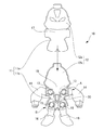
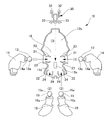
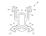
- FIG. 2 It is a front view of the doll toy concerning 1st Embodiment. It is a front view of a doll toy, and is a figure which shows the form which removed the front part division body. It is an exploded view of a doll toy. It is a front view of an elastic body.
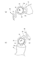
- A) is the A section enlarged view of FIG. 2
- (b) is the B section enlarged view of FIG.
- (A) is a perspective view of the joint body concerning 2nd Embodiment
- (b) is C arrow directional view of (a).
- FIG. 4C is a diagram illustrating a state where the pressing surface presses the second plane. It is a figure explaining the basic composition of the conventional doll toy.
- the doll toy 10 As shown in FIG. 1, the doll toy 10 according to the first embodiment includes a trunk 11, a head 12 provided on the trunk 11, and two left and right joints provided on the side of the trunk 11. 13, two left and right arm parts (movable parts) 14 connected to the body part 11 via the joint body 13, two right and left joint bodies 15 provided in the lower part of the body part 11, and the joint body 15 And two left and right leg portions (movable portions) 16 connected to the body portion 11 via the left and right sides.
- the doll toy 10 has an elastic body 30 that holds the position of the arm portion 14 and the position of the leg portion 16.
- the body 11 and the head 12 are formed by combining a front divided body 17 and a rear divided body 18.
- the front divided body 17 is a component in which the front portion 11 a of the body portion 11 and the front portion 12 a of the head portion 12 are integrally formed.
- the rear divided body 18 is a component in which the rear portion 11b of the trunk portion 11 and the rear portion 12b of the head portion 12 are integrally formed.
- the front divided body 17 and the rear divided body 18 are combined to form a hollow portion, and the joint body 13, the joint body 15, and the elastic body 30 are accommodated in the hollow portion.
- the left and right cutouts 21 through which the arm portion 14 passes are provided on the side portion of the rear divided body 18.
- two left and right notches 22 through which the leg portions 16 pass are provided.
- a holding portion 23 that holds the joint body 13 rotatably is formed near the inside of the notch 21.
- a holding portion 24 that holds the joint body 15 rotatably is formed in the vicinity of the inside of the notch 22.
- the inner surfaces of the holding portions 23 and 24 are formed in a concave curved surface shape.
- notches 21 and 22 having the same functions as the cutouts 21 and 22 and the holding parts 23 and 24 of the rear divided body 18 may be formed.
- the arm portion 14 has a shaft portion 14a.
- the joint body 13 is provided at the proximal end of the shaft portion 14a.
- the leg portion 16 has a shaft portion 16a.
- the joint body 15 is provided at the proximal end of the shaft portion 16a.
- the joint bodies 13 and 15 are so-called spherical joints, and have spherical surfaces 13a and 15a, respectively.
- the spherical surfaces 13 a and 15 a are sliding surfaces with respect to the inner surfaces of the holding portions 23 and 24.
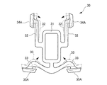
- the elastic body 30 includes a substantially rectangular annular portion 31, two left and right deformable portions 32 provided on the side of the annular portion 31, and two left and right provided on the lower portion of the annular portion 31. And a deforming portion 33.
- the annular portion 31 is positioned by being fitted to a positioning portion (a convex portion indicated by reference numeral 18a in FIG. 3) of the rear divided body.
- the configuration for positioning the elastic body 30 is not limited to the convex portion, but may be an arbitrary position regulating wall provided inside or outside the annular portion 31 or a fitting groove into which the annular portion 31 is fitted. You can choose from configurations.
- the deformation portion 32 extends from the side surface of the annular portion 31 toward the joint body 13 (see FIG. 2).
- a pressing surface 34 having a concave curved surface (for example, a spherical surface or a cylindrical surface) is formed at the tip of the deformable portion 32.
- the deformation part 33 is formed so as to branch from the lower part of the annular part 31 and extends toward the joint body 15 (see FIG. 2).
- a pressing surface 35 having a concave curved surface (for example, a spherical surface or a cylindrical surface) is formed at the tip of the deformation portion 33.
- Such deformable portions 32 and 33 are elastically deformable, and are assembled to the rear divided body in an elastically deformed form (for example, a form indicated by a two-dot chain line in FIG. 4).
- the pressing surfaces 34 and 35 press the spherical surfaces 13a and 15a (see FIG. 3) by the elastic force of the deforming portions 32 and 33.
- the material of the elastic body 30 can be selected from, for example, synthetic resin materials such as polyethylene and polypropylene, rubber materials, etc., but is preferably selected from materials that are more flexible than the peripheral parts such as the joint bodies 13 and 15. Further, if the elastic body 30 is an integrally molded product, the elastic body 30 can be manufactured at low cost, and assembly is facilitated.
- the joint body 13 is fitted into the holding portion 23 (arrow (1)). Further, the joint body 15 is fitted into the holding portion 24 (arrow (2)). At this time, the arm portion 14 and the leg portion 16 are passed through the notch 21 and the notch 22.
- the elastic body 30 is assembled to the rear divided body 18 (arrow (3)). At this time, the deformable portion 32 and the deformable portion 33 are incorporated between the left and right joint bodies 13 and between the left and right joint bodies 15 while being elastically deformed. Finally, the front divided body 17 (see FIG. 2) is put on the rear divided body 18. This completes the assembly.
- the elastic body 30 may be assembled first, and the arm part 14 and the leg part 16 may be assembled later.
- the deformable portions 32 and 33 of the elastic body 30 are deformed to secure a space for fitting the joint bodies 13 and 15.
- action of the elastic body 30 is demonstrated based on FIG.
- the arm joint body 13 is rotatable, but is pressed by the elastic force of the deformable portion 32 (force in the direction indicated by the arrow (4)). That is, the spherical surface 13 a is pressed by the pressing surface 34. For this reason, the joint body 13 does not rotate naturally. Therefore, the position of the arm portion 14 is maintained.
- the joint body 13 rotates against the frictional force generated between it and the pressing surface 34. Thereby, the user can move the arm part 14 to a favorite position.
- the position of the arm portion 14 is held by the elastic force from the deformation portion 32.
- the elastic body can be elastically deformed by being in contact with the joint body held by the body while being incorporated in the body, and can hold the joint by the elastic force due to the elastic deformation. The position of the movable part can be held.
- the leg joint 15 is also rotatable, but is pressed by the elastic force (the force in the direction indicated by the arrow (5)) due to the elastic deformation of the deformable portion 33. Yes. From this state, when the user operates and moves the leg portion 16, the joint body 15 rotates against the frictional force generated between the presser surface 35 and the joint body 15. When the operation of the leg portion 16 is stopped, the position of the leg portion 16 is held by the elastic force of the deformation portion 33.
- the position of the arm part 14 and the position of the leg part 16 can be hold
- the spherical surface of the joint body is pressed by a concave curved surface, but a polyhedral surface may be pressed by a flat surface.
- a polyhedral surface 41 is provided on the joint body 13 or the joint body 15.
- the polyhedral surface 41 is composed of a plurality of planes. That is, the polyhedral surface 41 includes a first plane 41a and a plurality of (here, four) substantially fan-shaped second planes 41b disposed so as to surround the first plane 41a.
- planar pressing surfaces 34A and 35A for pressing the polyhedral surface 41 are formed on the deformable portions 32 and 33, respectively.
- one plane (pressing surface) is associated with a plurality of planes.
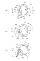
- the pressing surface 34A presses the first plane 41a and prevents the joint body 13 from rotating.
- the joint body 13 rotates.
- the pressing surface 34A is pushed by the corner portion 42 formed by the first plane 41a and the second plane 41b and escapes in a direction slightly away from the center of the joint body 13 ( Arrow (7)).
- the pressing surface 34A returns to a direction approaching the center of the joint body 13 and moves to the second plane 41b (arrow (8)).
- the presser surface 34A once goes back and then restores to overcome the corner portion 42.
- the movement of the pressing surface 34A is transmitted to the user's hand.
- the action of the pressing surface 34A similarly occurs when the pressing surface 34A shifts from the second plane 41b to the first plane 41a, or when it shifts from the second plane 41b to another second plane 41b. .
- the user obtains a click feeling by the movement of the pressing surfaces 34A, 35A transmitted to the hand.
- stepwise operation of the arm part 14 or the leg part 16 can be enjoyed.
- the arm part and the leg part are movable parts, but other parts such as the head may be movable parts, and the type and number of the movable parts are arbitrary according to the function required for the doll toy. Can be set.
Landscapes
- Toys (AREA)
Abstract
【課題】 腕部や脚部等の可動部の位置を安定的に保持でき、しかも、組み立てが簡単で、生産性が高い人形玩具を提供する。 【解決手段】 人形玩具10は、胴部11と、胴部11に回転可能に保持される関節体13および関節体15と、関節体13および関節体15をそれぞれの基端に備える腕部14および脚部16と、を有する。人形玩具10には、胴部11に組み込まれた状態で、胴部11に保持された関節体と当接して弾性変形可能であり、弾性変形による弾性力で関節体を押えて可動部の位置を保持する弾性体が設けられる。
Description
本考案は、人形玩具に関するものである。
従来、胴部に関節体を回転可能に保持させ、この関節体を介して腕部や脚部を胴部に連結することで、腕部や脚部を自由に動かすことができる人形玩具が知られている。この種の人形玩具では、関節体を胴部に単に嵌めただけでは、腕部や脚部が自然に動いてしまう。このため、関節体にプラスチック製のキャップを被せることにより、腕部や脚部の位置を保持することが一般に行われている。
しかし、腕部や脚部の関節体の各々にプラスチック製のキャップを被せると、部品点数が増えて部品コストが嵩む。そこで、キャップを使用せずに、腕部や脚部の位置を保持できる人形玩具が提案されている(たとえば、特許文献1参照)。
図9は、特許文献1に記載される人形玩具を示す図であり、人形玩具100では、胴部の後部101に軟質素材の保持部材102を組み込み、この保持部材102の溝部103に、頭部104、腕部105および脚部106のそれぞれの関節体107を差し込む。そして、胴部の前部(図示省略)を後部101に被せる。関節体107が軟質素材の保持部材102に保持されるため、頭部104、腕部105および脚部106の位置が保持される。
しかしながら、人形玩具100では、5本の溝部103に、頭部104、左右の腕部105、左右の脚部106のそれぞれの関節体107を1つずつ正確に差し込んでいく面倒な作業を伴う。このため、組立てに手間がかかる。また、保持部材102の5つの箇所に、複雑な溝部103を加工するため、部品の生産性が低下する。
そこで、本考案は、このような事情に鑑みてなされたものであり、その目的は、可動部の位置を保持でき、しかも、簡単に組み立てることができ、生産性を高めることもできる人形玩具を提供することにある。
本考案の人形玩具は、胴部と、前記胴部に回転可能に保持される関節体と、前記関節体を介して前記胴部に連結される少なくとも1個の可動部と、を有する人形玩具において、胴部に組み込まれた状態で、胴部に保持された関節体と当接して弾性変形可能であり、前記弾性変形による弾性力で前記関節体を押えて前記可動部の位置を保持する弾性体を有することを特徴とする。
上記考案では、前記関節体は、球面を有し、前記弾性体は、前記球面を押える凹曲面状の押え面を有することを特徴とする。
上記考案では、前記関節体は、多面体状の面を有し、前記弾性体は、前記多面体状の面を押える平面状の押え面を有することを特徴とする。
上記考案では、前記関節体は、多面体状の面を有し、前記弾性体は、前記多面体状の面を押える平面状の押え面を有することを特徴とする。
上記考案は、左右2個の腕部および左右2個の脚部を構成する4個の前記可動部を有し、前記弾性体は、前記胴部の中央に設けられる環状部と、前記環状部から前記腕部および前記脚部のそれぞれの前記関節体に向けて形成され、先端に前記押え面を有する4個の変形部と、を一体成形してなることを特徴とする。
本考案によれば、弾性変形した弾性体を胴部に組み込むことにより、可動部の位置を保持でき、しかも、簡単に組み立てることができ、生産性を高めることができる人形玩具を提供することができる。
(第1実施形態)
以下、添付図面を参照して、本考案を実施するための第1実施形態について詳細に説明する。なお、実施形態の説明の全体を通して同じ要素には同じ番号を付している。
以下、添付図面を参照して、本考案を実施するための第1実施形態について詳細に説明する。なお、実施形態の説明の全体を通して同じ要素には同じ番号を付している。
図1に示すように、第1実施形態の人形玩具10は、胴部11と、胴部11の上に設けられる頭部12と、胴部11の側部に設けられる左右2個の関節体13と、関節体13を介して胴部11に連結される左右2本の腕部(可動部)14と、胴部11の下部に設けられる左右2個の関節体15と、関節体15を介して胴部11に連結される左右2本の脚部(可動部)16と、を有する。また、人形玩具10は、腕部14の位置および脚部16の位置を保持する弾性体30を有する。
以下、各部の構成を図2、図3に基づいて詳細に説明する。
図2に示すように、胴部11と頭部12は、前部分割体17と後部分割体18とを組み合わせることで形成される。前部分割体17は、胴部11の前部11aと、頭部12の前部12aとを一体成形した部品である。後部分割体18は、胴部11の後部11bと、頭部12の後部12bとを一体成形した部品である。前部分割体17と後部分割体18とは、組み合わさることで中空部を形成し、その中空部に関節体13、関節体15、弾性体30を収納する。
図2に示すように、胴部11と頭部12は、前部分割体17と後部分割体18とを組み合わせることで形成される。前部分割体17は、胴部11の前部11aと、頭部12の前部12aとを一体成形した部品である。後部分割体18は、胴部11の後部11bと、頭部12の後部12bとを一体成形した部品である。前部分割体17と後部分割体18とは、組み合わさることで中空部を形成し、その中空部に関節体13、関節体15、弾性体30を収納する。
図3に示すように、後部分割体18の側部には、腕部14を通す左右2個の切欠き21が設けられる。後部分割体18の下部には、脚部16を通す左右2個の切欠き22が設けられる。また、切欠き21の内側近傍には、関節体13を回転可能に保持する保持部23が形成される。また、切欠き22の内側近傍には、関節体15を回転可能に保持する保持部24が形成される。保持部23,24の内面は、凹曲面状に形成される。
なお、前部分割体17(図2参照)においても、後部分割体18の切欠き21,22や保持部23,24と同様の機能を有する切欠きや保持部を形成してもよい。
腕部14は、軸部14aを有する。関節体13は、この軸部14aの基端に設けられる。脚部16は、軸部16aを有する。関節体15は、この軸部16aの基端に設けられる。関節体13,15は、いわゆる球体関節であり、それぞれ球面13a,15aを有する。球面13a,15aは、保持部23,24の内面に対する摺動面となる。
図4に示すように、弾性体30は、略長方形状の環状部31と、環状部31の側部に設けられる左右2個の変形部32と、環状部31の下部に設けられる左右2個の変形部33と、を有する。環状部31は、後部分割体の位置決め部(図3中、符号18aで示す凸部)に嵌ることで位置決めされる。なお、弾性体30を位置決めするための構成は、凸部に限定されるものではなく、環状部31の内側あるいは外側に設けた位置規制壁や、環状部31が嵌る嵌合溝など、任意の構成から選択できる。
変形部32は、環状部31の側面から関節体13(図2参照)に向けて延びる。変形部32の先端には、凹曲面(たとえば、球面や円筒面)状の押え面34が形成される。変形部33は、環状部31の下部から分岐するように形成され、関節体15(図2参照)に向けて延びる。変形部33の先端には、凹曲面(たとえば、球面や円筒面)状の押え面35が形成される。このような変形部32,33は、弾性変形可能であり、弾性変形した形態(たとえば、図4中、二点鎖線で示す形態)で、後部分割体に組み付けられる。変形部32,33の弾性力によって、押え面34,35は、球面13a,15a(図3参照)を押える。
弾性体30の材質は、たとえばポリエチレン、ポリプロピレン等の合成樹脂材料や、ゴム材料などから選択できるが、関節体13,15等の周辺部品よりも柔軟性を有する材料から選択されることが好ましい。また、弾性体30を一体成形品とすれば、弾性体30を低コストで製造でき、組み立ても容易になる。
次に、人形玩具10の組み立て方法の例を図3に基づいて説明する。
図3に示すように、先ず、関節体13を保持部23に嵌める(矢印(1))。また、関節体15を保持部24に嵌める(矢印(2))。この際、腕部14および脚部16を切欠き21および切欠き22に通すようにする。次に、弾性体30を後部分割体18に組み付ける(矢印(3))。このとき、変形部32および変形部33を弾性変形させながら、左右の関節体13の間および左右の関節体15の間に組み込む。最後に、前部分割体17(図2参照)を後部分割体18に被せる。これで組み立てが完了する。
図3に示すように、先ず、関節体13を保持部23に嵌める(矢印(1))。また、関節体15を保持部24に嵌める(矢印(2))。この際、腕部14および脚部16を切欠き21および切欠き22に通すようにする。次に、弾性体30を後部分割体18に組み付ける(矢印(3))。このとき、変形部32および変形部33を弾性変形させながら、左右の関節体13の間および左右の関節体15の間に組み込む。最後に、前部分割体17(図2参照)を後部分割体18に被せる。これで組み立てが完了する。
なお、人形玩具10の組み立てでは、先に弾性体30を組み付けておき、後から腕部14および脚部16を組み付けてもよい。この場合、関節体13,15を保持部23,24に嵌め込む際、弾性体30の変形部32,33を変形させて、関節体13,15を嵌め込むスペースを確保する。
続いて、弾性体30の作用を図5に基づいて説明する。
図5(a)に示すように、腕部用の関節体13は、回転可能ではあるが、変形部32の弾性力(矢印(4)で示す向きの力)で押えられている。すなわち、球面13aが押え面34で押えられている。このため、関節体13は、自然に回転することはない。よって、腕部14の位置が保持されている。
図5(a)に示すように、腕部用の関節体13は、回転可能ではあるが、変形部32の弾性力(矢印(4)で示す向きの力)で押えられている。すなわち、球面13aが押え面34で押えられている。このため、関節体13は、自然に回転することはない。よって、腕部14の位置が保持されている。
この状態から、使用者が腕部14を操作して動かすと、関節体13は、押え面34との間に生ずる摩擦力に抗して回転する。これにより、使用者は、腕部14を好きな位置に動かすことができる。そして、腕部14の操作を止めると、腕部14は、変形部32からの弾性力により位置が保持される。本実施の形態において、弾性体は、胴部に組み込まれた状態で、胴部に保持された関節体と当接して弾性変形可能であり、前記弾性変形による弾性力で前記関節体を押えて前記可動部の位置を保持することができる。
図5(b)に示すように、脚部用の関節体15についても、回転可能ではあるが、変形部33の弾性変形による弾性力(矢印(5)で示す向きの力)で押えられている。この状態から、使用者が脚部16を操作して動かすと、関節体15は、押え面35との間に生ずる摩擦力に抗して回転する。そして、脚部16の操作を止めると、脚部16は、変形部33の弾性力により位置が保持される。
以上、説明した第1実施形態の人形玩具によれば、腕部14の位置や脚部16の位置を保持することができる。また、弾性体30を組み込むだけでよいので、従来に比べ、組み立て工数が格段に減る。また、弾性体30には、従来のような複雑な溝部を形成する必要がないので、部品の生産性を高めることができる。
(第2実施形態)
次に、本考案にかかる第2実施形態の人形玩具を図6~図8に基づいて説明する。なお、前述した第1実施形態にかかる人形玩具10と共通する部位には同じ符号を付して、重複する説明を省略することとする。
次に、本考案にかかる第2実施形態の人形玩具を図6~図8に基づいて説明する。なお、前述した第1実施形態にかかる人形玩具10と共通する部位には同じ符号を付して、重複する説明を省略することとする。
前述した第1実施形態においては、関節体の球面を凹曲面で押えるようにしたが、この他、多面体状の面を平面で押えるようにしてもよい。たとえば、図6(a)および(b)に示すように、関節体13あるいは関節体15に、多面体状の面41を設ける。多面体状の面41は、複数の平面で構成される。すなわち、多面体状の面41は、第1平面41aと、この第1平面41aを囲うように配置される複数(ここでは4つ)の略扇状の第2平面41bと、からなる。
この場合、図7に示すように、変形部32,33に、多面体状の面41(図6参照)を押える平面状の押え面34A,35Aを形成する。このように第2実施形態では、複数の平面に対して、1つの平面(押え面)を対応させる。
押え面34A,35Aの作用を図8に基づいて説明する。ここでは、腕部用の押え面34Aの作用について説明し、脚部用の押え面35Aの作用は、押え面34Aと同様であるため、説明を省略する。
図8(a)では、押え面34Aは、第1平面41aを押えており、関節体13の回転を防いでいる。この状態から、使用者が腕部14を動かすと(矢印(6))、関節体13が回転する。すると、図8(b)に示すように、押え面34Aは、第1平面41aと第2平面41bで形成される角部42に押されて関節体13の中心から僅かに離れる方向に逃げる(矢印(7))。さらに関節体13が回転すると、図8(c)に示すように、押え面34Aは、関節体13の中心に近づく方向に戻り、第2平面41bに移行する(矢印(8))。
このように、図8(a)から(c)に至る過程において、押え面34Aは、一旦後退した後、復元することで、角部42を乗り越える。この押え面34Aの動きは、使用者の手に伝わる。なお、この押え面34Aの作用は、押え面34Aが第2平面41bから第1平面41aに移行するとき、あるいは、第2平面41bから他の第2平面41bに移行するときにも同様に生ずる。
この第2実施形態によれば、前述した第1実施形態の人形玩具10と同様の作用効果が得られることに加え、使用者は、手に伝わる押え面34A,35Aの動きによってクリック感を得ながら、腕部14あるいは脚部16の段階的な操作を楽しむことができる。
以上、実施形態を用いて本考案を説明したが、本考案の技術的範囲は上記実施形態に記載の範囲には限定されないことは言うまでもない。上記実施形態に、多様な変更または改良を加えることが可能であることが当業者に明らかである。またその様な変更または改良を加えた形態も本考案の技術的範囲に含まれ得ることが、実用新案登録請求の範囲の記載から明らかである。
たとえば、実施形態では、腕部と脚部を可動部としたが、頭部等の他の部位を可動部としてもよく、可動部の種類や個数は、人形玩具に求められる機能に応じて任意に設定可能である。
10 人形玩具
11 胴部
13 関節体
13a 球面
14 腕部(可動部)
15 関節体
15a 球面
16 脚部(可動部)
30 弾性体
32 変形部
33 変形部
34 押え面
34A 押え面
35 押え面
35A 押え面
41 多面体状の面
11 胴部
13 関節体
13a 球面
14 腕部(可動部)
15 関節体
15a 球面
16 脚部(可動部)
30 弾性体
32 変形部
33 変形部
34 押え面
34A 押え面
35 押え面
35A 押え面
41 多面体状の面
Claims (4)
- 胴部と、前記胴部に回転可能に保持される関節体と、前記関節体を介して前記胴部に連結される少なくとも1個の可動部と、を有する人形玩具において、
胴部に組み込まれた状態で、胴部に保持された関節体と当接して弾性変形可能であり、前記弾性変形による弾性力で前記関節体を押えて前記可動部の位置を保持する弾性体を有することを特徴とする人形玩具。 - 前記関節体は、球面を有し、
前記弾性体は、前記球面を押える凹曲面状の押え面を有することを特徴とする請求項1に記載の人形玩具。 - 前記関節体は、多面体状の面を有し、
前記弾性体は、前記多面体状の面を押える平面状の押え面を有することを特徴とする請求項1に記載の人形玩具。 - 左右2個の腕部および左右2個の脚部を構成する4個の前記可動部を有し、
前記弾性体は、前記胴部の中央に設けられる環状部と、前記環状部から前記腕部および前記脚部のそれぞれの前記関節体に向けて形成され、先端に前記押え面を有する4個の変形部と、を一体成形してなることを特徴とする請求項2または3に記載の人形玩具。
Priority Applications (1)
| Application Number | Priority Date | Filing Date | Title |
|---|---|---|---|
| CN201290000743.3U CN203763845U (zh) | 2011-09-07 | 2012-08-10 | 人偶玩具 |
Applications Claiming Priority (2)
| Application Number | Priority Date | Filing Date | Title |
|---|---|---|---|
| JP2011005268U JP3171849U (ja) | 2011-09-07 | 2011-09-07 | 人形玩具 |
| JP2011-005268U | 2011-09-07 |
Publications (1)
| Publication Number | Publication Date |
|---|---|
| WO2013035486A1 true WO2013035486A1 (ja) | 2013-03-14 |
Family
ID=47832823
Family Applications (1)
| Application Number | Title | Priority Date | Filing Date |
|---|---|---|---|
| PCT/JP2012/070444 Ceased WO2013035486A1 (ja) | 2011-09-07 | 2012-08-10 | 人形玩具 |
Country Status (3)
| Country | Link |
|---|---|
| JP (1) | JP3171849U (ja) |
| CN (1) | CN203763845U (ja) |
| WO (1) | WO2013035486A1 (ja) |
Cited By (2)
| Publication number | Priority date | Publication date | Assignee | Title |
|---|---|---|---|---|
| JP2022117501A (ja) * | 2021-01-29 | 2022-08-10 | 株式会社バンダイ | 玩具部品、人形玩具、及び、カバー部材 |
| JP7625742B1 (ja) | 2024-03-18 | 2025-02-03 | 株式会社バンダイ | 玩具 |
Families Citing this family (6)
| Publication number | Priority date | Publication date | Assignee | Title |
|---|---|---|---|---|
| JP2014168723A (ja) * | 2014-06-26 | 2014-09-18 | Bandai Co Ltd | 人形体 |
| TWI571296B (zh) * | 2015-01-08 | 2017-02-21 | 中興保全股份有限公司 | 可調姿勢之玩偶 |
| JP7226970B2 (ja) * | 2018-11-06 | 2023-02-21 | 株式会社バンダイ | 連結玩具 |
| JP6952152B2 (ja) * | 2020-03-23 | 2021-10-20 | 株式会社バンダイ | 人形体の屈曲構造及びそれを用いた人形体並びに人形体の製造方法 |
| CN112169349B (zh) * | 2020-10-20 | 2025-03-14 | 中山市金三模特道具有限公司 | 人偶球形关节及人偶骨架 |
| JP7474897B1 (ja) | 2023-09-01 | 2024-04-25 | 株式会社バンダイ | 模型玩具及び関節構造体 |
Citations (7)
| Publication number | Priority date | Publication date | Assignee | Title |
|---|---|---|---|---|
| JPS50156184U (ja) * | 1974-06-11 | 1975-12-24 | ||
| JPS5192290U (ja) * | 1975-01-23 | 1976-07-23 | ||
| JPS5298590U (ja) * | 1976-01-23 | 1977-07-25 | ||
| JPH0331355Y2 (ja) * | 1985-09-26 | 1991-07-03 | ||
| JPH075695U (ja) * | 1993-06-29 | 1995-01-27 | 株式会社パンサー | 人形玩具 |
| JPH07112516B2 (ja) * | 1992-03-04 | 1995-12-06 | 株式会社バンダイ | 玩具装置 |
| JP2524889Y2 (ja) * | 1991-11-26 | 1997-02-05 | 株式会社エンジェル | 人形玩具 |
-
2011
- 2011-09-07 JP JP2011005268U patent/JP3171849U/ja not_active Expired - Lifetime
-
2012
- 2012-08-10 WO PCT/JP2012/070444 patent/WO2013035486A1/ja not_active Ceased
- 2012-08-10 CN CN201290000743.3U patent/CN203763845U/zh not_active Expired - Lifetime
Patent Citations (7)
| Publication number | Priority date | Publication date | Assignee | Title |
|---|---|---|---|---|
| JPS50156184U (ja) * | 1974-06-11 | 1975-12-24 | ||
| JPS5192290U (ja) * | 1975-01-23 | 1976-07-23 | ||
| JPS5298590U (ja) * | 1976-01-23 | 1977-07-25 | ||
| JPH0331355Y2 (ja) * | 1985-09-26 | 1991-07-03 | ||
| JP2524889Y2 (ja) * | 1991-11-26 | 1997-02-05 | 株式会社エンジェル | 人形玩具 |
| JPH07112516B2 (ja) * | 1992-03-04 | 1995-12-06 | 株式会社バンダイ | 玩具装置 |
| JPH075695U (ja) * | 1993-06-29 | 1995-01-27 | 株式会社パンサー | 人形玩具 |
Cited By (5)
| Publication number | Priority date | Publication date | Assignee | Title |
|---|---|---|---|---|
| JP2022117501A (ja) * | 2021-01-29 | 2022-08-10 | 株式会社バンダイ | 玩具部品、人形玩具、及び、カバー部材 |
| JP7621301B2 (ja) | 2021-01-29 | 2025-01-24 | 株式会社バンダイ | 玩具部品、人形玩具、及び、カバー部材 |
| JP2025061264A (ja) * | 2021-01-29 | 2025-04-10 | 株式会社バンダイ | 玩具部品、人形玩具、及び、カバー部材 |
| JP7625742B1 (ja) | 2024-03-18 | 2025-02-03 | 株式会社バンダイ | 玩具 |
| JP2025143044A (ja) * | 2024-03-18 | 2025-10-01 | 株式会社バンダイ | 玩具 |
Also Published As
| Publication number | Publication date |
|---|---|
| JP3171849U (ja) | 2011-11-17 |
| CN203763845U (zh) | 2014-08-13 |
Similar Documents
| Publication | Publication Date | Title |
|---|---|---|
| JP3171849U (ja) | 人形玩具 | |
| CN101376062A (zh) | 关节及其连接装置 | |
| KR20160120732A (ko) | 휴머노이드 로봇에 제공되도록 제작된 손의 작동 | |
| JP7129217B2 (ja) | 人形の腰部関節構造及び人形 | |
| KR102699372B1 (ko) | 인형 | |
| CN104519970B (zh) | 人形体的手腕的关节构造及人形体 | |
| CN108579099B (zh) | 可转换的玩具 | |
| JP3182540U (ja) | 人形玩具の可動連結部材及び人形玩具 | |
| JP2007301704A (ja) | ロボット用連結部材の結合機構と歩行型ロボット | |
| JP7105105B2 (ja) | 人形の関節構造及び人形 | |
| US9586153B2 (en) | Toy figure with movable appendage | |
| JP6144119B2 (ja) | 人形の関節構造 | |
| JP3185950U (ja) | 人形玩具の2段階関節部材及び人形玩具 | |
| JP5781713B1 (ja) | 関節構造 | |
| KR200285515Y1 (ko) | 다변형 조립완구 | |
| US20120329363A1 (en) | Toy Figure with Articulating Limb | |
| JP2024071570A (ja) | 連結パーツ、インジェクションキットおよび人型玩具 | |
| KR20110022421A (ko) | 다변형조립완구 | |
| CN113271813A (zh) | 交互式角色控制系统 | |
| JP3722814B2 (ja) | 人形玩具の肘部又は膝部の関節構造 | |
| JP6568629B2 (ja) | 人形体の手および人形体 | |
| JP6069233B2 (ja) | 人形体の手首の関節構造、人形体の足首の関節構造、および人形体 | |
| JP5293505B2 (ja) | 一体成型してなる複合スイッチの操作機構 | |
| CN202087043U (zh) | 用于塑料部件的活动连接结构 | |
| KR200285464Y1 (ko) | 관절이 움직이는 종이모형완구 |
Legal Events
| Date | Code | Title | Description |
|---|---|---|---|
| WWE | Wipo information: entry into national phase |
Ref document number: 201290000743.3 Country of ref document: CN |
|
| 121 | Ep: the epo has been informed by wipo that ep was designated in this application |
Ref document number: 12829909 Country of ref document: EP Kind code of ref document: A1 |
|
| NENP | Non-entry into the national phase |
Ref country code: DE |
|
| 122 | Ep: pct application non-entry in european phase |
Ref document number: 12829909 Country of ref document: EP Kind code of ref document: A1 |