WO2013031698A1 - 三次元画像表示装置 - Google Patents
三次元画像表示装置 Download PDFInfo
- Publication number
- WO2013031698A1 WO2013031698A1 PCT/JP2012/071482 JP2012071482W WO2013031698A1 WO 2013031698 A1 WO2013031698 A1 WO 2013031698A1 JP 2012071482 W JP2012071482 W JP 2012071482W WO 2013031698 A1 WO2013031698 A1 WO 2013031698A1
- Authority
- WO
- WIPO (PCT)
- Prior art keywords
- display
- dimensional
- image data
- dimensional image
- image
- Prior art date
- Legal status (The legal status is an assumption and is not a legal conclusion. Google has not performed a legal analysis and makes no representation as to the accuracy of the status listed.)
- Ceased
Links
Images




Classifications
-
- H—ELECTRICITY
- H04—ELECTRIC COMMUNICATION TECHNIQUE
- H04N—PICTORIAL COMMUNICATION, e.g. TELEVISION
- H04N13/00—Stereoscopic video systems; Multi-view video systems; Details thereof
- H04N13/30—Image reproducers
- H04N13/302—Image reproducers for viewing without the aid of special glasses, i.e. using autostereoscopic displays
- H04N13/307—Image reproducers for viewing without the aid of special glasses, i.e. using autostereoscopic displays using fly-eye lenses, e.g. arrangements of circular lenses
-
- G—PHYSICS
- G02—OPTICS
- G02B—OPTICAL ELEMENTS, SYSTEMS OR APPARATUS
- G02B3/00—Simple or compound lenses
- G02B3/0006—Arrays
- G02B3/0037—Arrays characterized by the distribution or form of lenses
- G02B3/0056—Arrays characterized by the distribution or form of lenses arranged along two different directions in a plane, e.g. honeycomb arrangement of lenses
-
- G—PHYSICS
- G02—OPTICS
- G02B—OPTICAL ELEMENTS, SYSTEMS OR APPARATUS
- G02B30/00—Optical systems or apparatus for producing three-dimensional [3D] effects, e.g. stereoscopic images
- G02B30/20—Optical systems or apparatus for producing three-dimensional [3D] effects, e.g. stereoscopic images by providing first and second parallax images to an observer's left and right eyes
- G02B30/26—Optical systems or apparatus for producing three-dimensional [3D] effects, e.g. stereoscopic images by providing first and second parallax images to an observer's left and right eyes of the autostereoscopic type
- G02B30/27—Optical systems or apparatus for producing three-dimensional [3D] effects, e.g. stereoscopic images by providing first and second parallax images to an observer's left and right eyes of the autostereoscopic type involving lenticular arrays
-
- G—PHYSICS
- G09—EDUCATION; CRYPTOGRAPHY; DISPLAY; ADVERTISING; SEALS
- G09G—ARRANGEMENTS OR CIRCUITS FOR CONTROL OF INDICATING DEVICES USING STATIC MEANS TO PRESENT VARIABLE INFORMATION
- G09G3/00—Control arrangements or circuits, of interest only in connection with visual indicators other than cathode-ray tubes
- G09G3/001—Control arrangements or circuits, of interest only in connection with visual indicators other than cathode-ray tubes using specific devices not provided for in groups G09G3/02 - G09G3/36, e.g. using an intermediate record carrier such as a film slide; Projection systems; Display of non-alphanumerical information, solely or in combination with alphanumerical information, e.g. digital display on projected diapositive as background
- G09G3/003—Control arrangements or circuits, of interest only in connection with visual indicators other than cathode-ray tubes using specific devices not provided for in groups G09G3/02 - G09G3/36, e.g. using an intermediate record carrier such as a film slide; Projection systems; Display of non-alphanumerical information, solely or in combination with alphanumerical information, e.g. digital display on projected diapositive as background to produce spatial visual effects
Definitions
- the present invention relates to a three-dimensional image display device.
- Patent Document 1 a display device that displays a stereoscopic image and a plan view is known (for example, Patent Document 1).
- the three-dimensional image display device includes an input unit that inputs image data, and a first image conversion unit that converts the image data into first display image data having two-dimensional information.
- a plurality of display pixels are two-dimensionally arranged, and a display unit that emits a light beam from the plurality of display pixels according to the first display image data, and a light beam emitted from the plurality of display pixels are combined.
- a microlens array in which a plurality of microlenses forming a three-dimensional image or a two-dimensional image are arranged two-dimensionally.
- the three-dimensional image display device further includes a second image conversion unit that converts the image data into second display image data having three-dimensional information,
- the display unit preferably emits a light beam from a plurality of display images according to the first and second display image data.
- the three-dimensional display device in the three-dimensional image display device according to the second aspect, it is preferable to display the three-dimensional image and the two-dimensional image on the same plane.
- the three-dimensional display device includes a plurality of display pixel groups each including a plurality of display pixels arranged two-dimensionally, a display unit arranged two-dimensionally, and each of the plurality of display pixel groups.
- the display pixels are controlled based on the three-dimensional image data, a plurality of optical members that are two-dimensionally arranged to project the corresponding display pixel group, a three-dimensional image data output unit that outputs three-dimensional image data, and A first display control unit that displays the three-dimensional image data as a three-dimensional image via the optical member, a two-dimensional image data output unit that outputs the two-dimensional image data, and a plurality of two-dimensional portions of the two-dimensional image data.
- a plurality of two-dimensional display partial images based on the conversion unit that divides the image data and converts each of the two-dimensional partial image data into a plurality of partial image data for two-dimensional display;
- Each in the data By controlling the corresponding display pixel group, each of the two-dimensional image data is displayed as a two-dimensional image by synthesizing the projection images by the optical members related to the plurality of display pixel groups corresponding to the plurality of display two-dimensional image data.
- the three-dimensional display device includes a plurality of display pixel groups each including a plurality of display pixels arranged two-dimensionally, a display unit arranged two-dimensionally, and each of the plurality of display pixel groups.
- the display pixels are controlled based on the three-dimensional image data, a plurality of optical members that are two-dimensionally arranged to project the corresponding display pixel group, a three-dimensional image data output unit that outputs three-dimensional image data, and A first display control unit that displays the three-dimensional image data as a three-dimensional image through the optical member, a two-dimensional image data output unit that outputs the two-dimensional image data, and a plurality of two-dimensional portions of the two-dimensional image data.
- each of the two-dimensional image data is displayed as a two-dimensional image by synthesizing projection images by optical members related to the plurality of display pixel groups corresponding to the plurality of display two-dimensional image data.
- a second display control unit that controls the display unit, and a third display control unit that displays the three-dimensional image and the two-dimensional image on the same screen.
- the third display control unit further controls the display unit to display the three-dimensional image and the two-dimensional image on the same screen. It is preferable to provide.
- the two-dimensional image data further includes an extraction unit that extracts the two-dimensional information included in the three-dimensional image data.
- the output unit preferably outputs the two-dimensional information extracted by the extraction unit as two-dimensional image data.
- the conversion unit is configured by a two-dimensional member on which the two-dimensional display partial image data is reproduced, and is optical. It is preferable to arrange between the optical member and the display pixel with respect to the optical axis direction of the member.
- the optical member has a two-dimensional image equal to or longer than the lens surface of the optical member or the focal length of the optical member. It is preferable to project on a remote aerial image plane.
- the optical member is preferably constituted by a microlens or a cylindrical lens.
- the two-dimensional image data can be displayed as a two-dimensional image, A two-dimensional image can be displayed on the same screen.
- FIG. 1 The block diagram explaining the principal part structure of the three-dimensional image display apparatus by embodiment of this invention
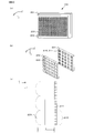
- the figure explaining an example of the structure of the monitor with which the three-dimensional display device by embodiment is equipped The figure which showed typically the relation between a display pixel, a display microlens array, and a light spot displayed
- FIG. 3 is expanded two-dimensionally
- the figure explaining the relationship between the display microlens and the pattern light section The figure explaining the relationship between a display microlens and a pattern
- the figure explaining the pattern at the time of expanding an area division to a base microlens The figure explaining the pattern when the light spot is decentered with respect to the center position of the base microlens
- the figure explaining the display pixel in the case of displaying a two-dimensional image The figure which shows an example of the image displayed two-dimensionally
- the figure explaining the pattern in the case of displaying a two-dimensional image The figure which shows a mode that the pattern shown in FIG. 11 is displayed two-dimensionally on a display aerial image plane
- the 3D image display apparatus includes a personal computer having a monitor for displaying an image.
- a personal computer having a monitor for displaying an image.
- an image corresponding to image data having three-dimensional information generated by a known plenoptic camera (Plenoptics Camera) or a light field camera (Light ⁇ Field Camera) can be observed as a three-dimensional image. Is displayed. Furthermore, images corresponding to image data corresponding to two-dimensional information such as characters and command buttons for performing various operation inputs are displayed so as to be observable as a two-dimensional image. Details will be described below.
- FIG. 1 is a block diagram for explaining a main configuration of a 3D image display apparatus 100 according to an embodiment.
- the three-dimensional image display device 100 includes a control circuit 101, an HDD 102, a monitor control circuit 103, a monitor 104, a memory 105, an input member 106, a memory card interface 107, and an external interface 108.
- the input member 106 is an operation member such as a keyboard having a switch or button operated by a user, a mouse, or the like.
- the input member 106 is operated by the user when selecting a menu or setting desired by the user from the menu screen displayed on the monitor 104 and executing the selected menu or setting.
- an image file corresponding to a moving image or a still image taken with a digital camera is recorded.
- the external interface 108 performs data communication with an external device such as a digital camera via, for example, a USB interface cable or a wireless transmission path.
- the three-dimensional image display apparatus 100 inputs an image file or the like from the memory card 207a or an external device via the memory card interface 107 or the external interface 108.
- the input image file is recorded on the HDD 102 under the control of the control circuit 101.
- An image file generated by the digital camera is recorded on the HDD 102 by the control circuit 101.
- Various programs executed by the control circuit 101 are recorded in the HDD 102.
- the control circuit 101 is a microcomputer that controls the three-dimensional image display device 100, and includes a CPU, a ROM, and other peripheral circuits.
- the control circuit 101 includes an extraction unit 101a, a three-dimensional output unit 101b, a three-dimensional display control unit 101c, a two-dimensional output unit 101d, a display two-dimensional data conversion unit 101e, a two-dimensional display control unit 101f, A display control unit 101g is functionally provided.
- the extraction unit 101a extracts two-dimensional information included in image data having three-dimensional information (hereinafter, three-dimensional image data) as two-dimensional display data.
- the two-dimensional information includes characters, command buttons for performing various operation inputs, window frames, and the like.
- the three-dimensional output unit 101b reads out three-dimensional image data recorded in the HDD 102, for example. Based on the 3D image data, the 3D display control unit 101c controls display pixels included in the monitor 104 described later to display the 3D image data as a 3D image.
- the two-dimensional output unit 101d reads the two-dimensional image data recorded in the HDD 102, for example.
- the display two-dimensional data conversion unit 101e divides the two-dimensional display data extracted by the extraction unit 101a and the two-dimensional image data read by the two-dimensional output unit 101d into a plurality of two-dimensional partial image data. Then, the display two-dimensional data conversion unit 101e converts each of the two-dimensional partial image data into a plurality of two-dimensional display partial image data. In other words, the display two-dimensional data conversion unit 101e converts the image data into two-dimensional display partial image data having two-dimensional information.
- the two-dimensional display control unit 101f controls display pixels included in the monitor 104 described later based on the two-dimensional display partial image data, and displays the two-dimensional image data and the two-dimensional display data as a two-dimensional image.
- the display control unit 101g displays the three-dimensional image and the two-dimensional image on the same screen, that is, on the monitor 104.
- the details of the extraction unit 101a, the three-dimensional output unit 101b, the three-dimensional display control unit 101c, the two-dimensional output unit 101d, the display two-dimensional data conversion unit 101e, the two-dimensional display control unit 101f, and the display control unit 101g are as follows. The description will be described later.
- the memory 105 is a working memory of the control circuit 101, and is composed of, for example, an SDRAM.
- the monitor 104 is, for example, a liquid crystal monitor, and is controlled by the monitor control circuit 103 to display an image corresponding to display image data, a menu screen for performing various settings, and the like.
- the monitor 104 will be described with reference to FIG.
- the coordinate system is set with the horizontal direction of the display surface of the monitor 104 as the x axis, the vertical direction as the y axis, and the direction perpendicular to the xy plane (display surface of the monitor 104) as the z axis.
- 2 (a) is a perspective view of the monitor 104 when the monitor 104 is viewed from the z-axis direction user side
- FIG. 2 (b) is a partially enlarged view of FIG. 2 (a).
- FIG. 2C is a diagram schematically showing a cross section of the monitor 104 in the z-axis direction.
- the monitor 104 includes a display 201 and a display microlens array 202.
- the display 201 is constituted by, for example, a liquid crystal display having a backlight, an organic EL display, or the like, and has a plurality of display pixel groups 210 arranged in a two-dimensional manner.
- Each of the plurality of display pixel groups 210 includes a plurality of display pixels 211 arranged two-dimensionally.
- the number of display pixels 211 is drawn smaller than the actual number.
- the display pixel 211 is controlled by the monitor control circuit 103 described above and emits light corresponding to the display image data.
- the display microlens array 202 is composed of a plurality of display microlenses 220 arranged two-dimensionally. As shown in FIG. 2B, the display microlenses 220 are arranged in an arrangement pattern corresponding to the plurality of display pixel groups 210. Further, as shown in FIG. 2C, the display microlens array 202 is arranged on the user side in the z-axis direction at a position separated from the display pixel 211 by the focal length f of the display microlens 220. Each display microlens 220 projects light from the display pixel 211 on a predetermined image plane on the user side in the z-axis direction according to image data.
- the display principle of the monitor 104 is the reverse of the principle of plain optics.
- the principle of the plain optics will be briefly described with reference to FIG.
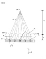
- FIG. 3 is a diagram showing a relationship among the display pixel 211, the display microlens array 202, and the light spot LP to be displayed.
- the display microlens array 202 is provided at a position away from the display pixel 211 in the z-axis direction by the focal length f of the display microlens 220.
- the light spot LP is at a position 4 f away from the display microlens array 202 toward the user side in the z-axis direction.
- the case where the light beam LF is traced from the light spot LP toward the display pixel 211 is the plain optics.
- the light beam LF from the light spot LP passes through the plurality of display microlenses 220 and is focused at a position of 4f / 3 from the display microlens 220.
- the display microlens 220 is disposed at a distance f from the display pixel 211 in the z-axis direction, the light beam LF that has passed through each display microlens 220 is incident on the incident display microlens 220.
- the display pixel 211 corresponding to each becomes a spread image.
- this widened image is called an optical section, and the shape of the optical section is called a pattern Pt.
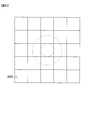
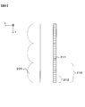
- FIG. 4 shows a case where the pattern Pt is developed two-dimensionally.
- the arrangement of the display microlenses 220 is drawn as a square. That is, according to the principle of Plenoptics, the light intensity (luminance) of the light spot LP shown in FIG. 3 is distributed to the pattern Pt shown in FIG. In FIG. 4, the pattern Pt is shown with diagonal lines.
- an aerial image having a depth is displayed by reversing the principle of the above-mentioned pre-optics, that is, by projecting the light beam radiated from the display pixel 211 through the display microlens 220.
- the pattern Pt shown in FIG. 4 is allocated on the display pixel 211 constituting the display device 202.
- the pattern Pt assigned to the display pixel 211 is projected by the display microlens 220 to form an image at the light spot LP.
- the luminous fluxes traveling in multiple directions radiated from the display pixels 211 included in each pattern Pt include the luminous flux in the direction of focusing on the light spot LP, that is, the incident angle of the incident luminous flux LF to the display pixel 211 described above. This is because light beams that radiate at the same angle are included. Therefore, an aerial image is formed at a position away from the display microlens array 202 by a distance 4f in the z-axis direction.
- FIG. 5 how many or which display microlens 220 corresponds to which pattern Pt is explained by projecting the spread of the light beam LF from the light spot LP onto the display microlens 220.
- the light beam LF spreading from the light spot LP is shown for the case where the position of the light spot LP in the z-axis direction is the focal length f of the display microlens 220 and the distance 2f that is twice that. Yes.
- the spread of the light beam LF when the position of the light spot LP in the z-axis direction is the distance f is indicated by a broken line, and the case of the distance 2f is indicated by a one-dot chain line.
- the spread of the light beam LF is defined by the display microlens 220, so that the light beam LF is incident on one display microlens 220. To do.
- the display microlens 220 corresponding to one light spot LP is determined.
- the light beam LF spreads as light of a circular aperture over the entire region immediately below the display microlens 220. For this reason, when all the display pixels 211 included in the circle inscribed in the square region emit light, the pattern Pt is projected and an aerial image is formed at the light spot LP.
- the absolute value of the position of the light spot LP in the z-axis direction is smaller than the focal length f, the light beam LF spreads without converging in the region immediately below the display microlens 220.
- the angle of the light beam LF spreading from the light spot LP is defined by the F value of the display microlens 220, and the maximum aperture (minimum F) is defined. Therefore, the incident light beam LF is limited by the spread angle, and the pattern Pt is Stay in the covered area.
- FIG. 6 shows a display microlens 220 related to this case.
- the related display microlens 220 is itself, that is, the display microlens 220 (hereinafter referred to as the base microlens 220a) disposed coaxially with the light spot LP and the z-axis direction.
- the eight display microlenses 220 are adjacent to each other.
- the pattern Pt exists in the covered region indicated by the oblique lines in FIG.
- the pattern Pt corresponding to each display microlens 220 is a region indicated by oblique lines in FIG.
- the covering region of one base microlens 220a is divided and distributed to adjacent display microlenses 220.
- the total area when the divided and distributed covering areas (partial areas) are integrated becomes an opening area of one display microlens 220. Therefore, the size of the entire area of the pattern Pt is the same at any position of the light spot LP. Therefore, when calculating the total area by adding the partial areas, the display micros to which the partial areas belong are displayed. It is only necessary to determine the lens 220.
- FIG. 5 shows the relationship between the position of the light spot LP in the z-axis direction and the magnification, that is, the number of display microlenses 220 adjacent to the base microlens 220a, and this is applied to a virtual aperture region.
- a method is used in which an aperture region is divided by an array of display microlenses 220 reduced in magnification, and a fragment of the aperture region is arranged at the same position in the display microlens 220 defined by this.
- An example will be described in which a square circumscribing the opening area is reduced by a magnification of 2 and the opening area is divided (area division) by the arrangement of the display microlenses 220.
- FIG. 7 shows a pattern Pt when the above region division is developed on the base microlens 220a.
- a magnification that is, a pattern Pt for the light spot LP is obtained.
- the diameter of the display microlens 220 the size of one side of the microlens
- the opening region is divided by a g / m-wide grid.
- There is also a negative sign in the ratio m When the sign of the ratio m is negative, it is assumed that there is a light spot LP on the display pixel 211 side from the display microlens 220.
- the product of the area covered by the display microlens 220 and the number of display microlenses 220 is substantially equal to the total number of display pixels 211 included in the display pixel group 210. For this reason, forming light spots LP corresponding to a plurality of decentered points in one display microlens 220 is equivalent to superimposing and projecting the reproduced pattern Pt on the display pixel 211. . That is, the light beam LF from each decentered light spot LP is superimposed on the display pixel 211.
- magnification is 1, this calculation is merely an interpolation operation and does not substantially contribute to the resolution improvement. This indicates that if the image is formed near the apex of the display microlens 220, information in the depth direction is optically lost.
- FIG. 8 shows a divided region for the light spot LP decentered to the left with respect to the center position of the base microlens 220a.
- the height (position) of the light spot LP is 2f, decentered by p from the center of the base microlens 220a (with the lens diameter g) to the left in FIG.
- the point O ⁇ b> 1 indicates the eccentric light spot LP
- the point O ⁇ b> 2 indicates the center position of the display microlens 220.
- the divided region shown in FIG. 8 is obtained.
- the coordinates of the center position are set to (0, 0), and -g / 2, -g / 4, 0, g / 4 with respect to the x-axis and y-axis, respectively.
- G / 2 position patterns, and the divided areas and total areas thereof are integrated, so that 16 light spot groups can be obtained for one microlens 120.
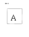
- FIG. 10 shows that an example of an image to be two-dimensionally displayed is the letter “A”.
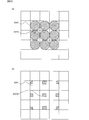
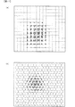
- a pattern Pt is assigned to the composite display pixel 212 as shown in FIG.
- FIG. 11A shows a case where the display microlenses 220 are in a square arrangement
- FIG. 11B shows a case where the display microlenses 220 are in a honeycomb arrangement.
- the display aerial image plane S is not limited to the one formed at a distance of 4 f, but is formed at a position longer than the focal length f of the display microlens 220 or the lens surface of the display microlens 220. There may be.
- the display aerial image plane S is formed at a desired position by the user operating the input member 106.
- each light spot LP constituting the aerial image.
- the pattern Pt assigned to the composite display pixel 212 included in the region covered by one display microlens 220 that is, the 16 composite display pixels 212.
- the projected image by the display microlens 220 is synthesized. Therefore, when one display microlens 220 contributes to the formation of 16 light spots LP, the composite display within the region covered by the display microlens 220 is displayed for one display microlens 220.
- the output of 16 times the output of the pixel 212 is required, and all these outputs need to be combined.
- each composite display pixel 212 forming one light spot LP when the size of each composite display pixel 212 forming one light spot LP is distributed, the output is distributed so as to be added to the output of the composite display pixel 212 at the adjacent light spot LP.
- the output of 16 composite display pixels 212 is superimposed on one light spot LP, and the pixel output requires a dynamic range of 16 times at maximum.
- the control circuit 101 of the three-dimensional image display device 100 is formed at a predetermined height in the z-axis direction from the display microlens array 202 by assigning the pattern Pt to the display pixels 211 as shown in FIG.
- a two-dimensional image such as characters is displayed on the display aerial surface S.
- the two-dimensional output unit 101d reads from the HDD 102 two-dimensional image data to be displayed on the monitor 104 as a two-dimensional image.
- the two-dimensional image data read from the two-dimensional output unit 101d has the same content as the image data output to a display used for displaying a normal two-dimensional image.
- the display two-dimensional data conversion unit 101e divides the two-dimensional image data read by the two-dimensional output unit 101d into partial image data corresponding to the plurality of display microlenses 220. In the example shown in FIG. 10, the display two-dimensional data conversion unit 101e divides the image into 16 partial image data. Then, the display two-dimensional data conversion unit 101e generates two-dimensional display partial image data for each of the divided partial image data.
- the two-dimensional display partial image data is image data representing a pattern Pt as shown in FIG.
- the two-dimensional display control unit 101f assigns the pattern Pt indicated by the display partial image data to the composite display pixel 212. In other words, the two-dimensional display control unit 101f instructs the monitor control circuit 103 to cause the composite display pixel 212 disposed at a position corresponding to the two-dimensional display partial image data to emit light.
- the control circuit 101 of the three-dimensional display device 100 displays, for example, a certain window among the plurality of windows displayed on the monitor 104 in three dimensions, and displays other windows and characters indicating various operation commands in two dimensions. Display.
- the control circuit 101 three-dimensionally displays an image corresponding to the image data on the monitor 104 and two-dimensionally displays a portion corresponding to the frame portion of the image.
- the 3D output unit 101b reads from the HDD 102 3D image data to be displayed on the monitor 104 as a 3D image.
- the 3D image data read from the 3D output unit 101b is 3D information acquired by, for example, a plain optics camera, that is, image data representing the pattern Pt.
- the extraction unit 101a extracts, as 2D display data, information to be displayed in 2D corresponding to, for example, a window frame from the read 3D image data.
- the extracted two-dimensional display data is converted into display partial image data by the above-described display two-dimensional data conversion unit 101e.
- the 3D display control unit 101c instructs the monitor control circuit 103 to generate display 3D image data using image data that has not been extracted by the extraction unit 101a among the read 3D image data. . Then, the 3D display control unit 101c assigns display 3D image data, that is, a pattern Pt indicating 3D information, to the display pixel 211 to emit light. At this time, when the center position (optical axis) of the microlens included in the plenoptic camera that generated the three-dimensional image data is different from the center position (optical axis) of the display microlens 220, that is, the display microlens 220.
- the 3D display control unit 101c When the central axis and the light spot LP are not on the same axis in the z-axis direction, the 3D display control unit 101c performs normalization processing on the read 3D image data. That is, the 3D display control unit 101c moves the position of the 3D image data on the xy plane so that the light spot LP corresponding to each pattern Pt is located on the central axis of the base microlens 220a.
- the three-dimensional display control unit 101c converts the pattern Pt corresponding to the display microlens 220 adjacent to each base microlens 220a to a point-symmetrical position about the base microlens 220a, thereby displaying three-dimensional image data for display. Is generated.
- the traveling direction of light in the plenoptic camera at the time of acquiring image data is opposite to the traveling direction of light in the monitor 104, unevenness in the depth direction (z-axis direction) of the aerial image and when shooting It is for making the unevenness
- the 3D display control unit 101c assigns the pattern Pt indicated by the generated display 3D image data to the display pixel 211.
- the display control unit 101g controls the two-dimensional display control unit 101f and the three-dimensional display control unit 101c to display two-dimensionally a three-dimensional image having a depth in the z-axis direction and a predetermined height in the z-axis direction.
- the two-dimensional image is displayed on the same screen, that is, the monitor 104.
- the two-dimensional display control unit 101f instructs the monitor control circuit 103 to provide a two-dimensional image corresponding to the partial image data for two-dimensional display at a predetermined height from the monitor 104, such as a window frame, a character, and an operation button. Is displayed two-dimensionally.
- the 3D display control unit 101c instructs the monitor control circuit 103 to display an image corresponding to the display 3D image data as an aerial image.
- a plurality of display pixel groups 210 including a plurality of display pixels 211 arranged two-dimensionally are two-dimensionally arranged on the display device 201.
- the plurality of display microlenses 220 are two-dimensionally arranged corresponding to each of the plurality of display pixel groups 210 and project the corresponding display pixel group 210.
- the three-dimensional output unit 101b outputs three-dimensional image data, and the three-dimensional display control unit 101c controls the display pixels 211 based on the three-dimensional image data to obtain the three-dimensional image data via the display microlens 210. Display as original image.
- the two-dimensional output unit 101d outputs two-dimensional image data
- the display two-dimensional data conversion unit 101 divides the two-dimensional image data into a plurality of two-dimensional partial image data
- each of the two-dimensional partial image data is divided into a plurality of two-dimensional image data. Convert to partial display data for dimension display.
- the two-dimensional display control unit 101f controls the display pixel group 210 corresponding to each of the plurality of two-dimensional display partial image data based on the two-dimensional display partial image data, and each of the two-dimensional image data is controlled.
- the two-dimensional image is displayed by synthesizing the projection image by the display microlens 220 regarding the plurality of display pixel groups 210 corresponding to the plurality of display two-dimensional image data. Therefore, two-dimensional information such as characters and window frames is displayed two-dimensionally on the display aerial image plane S, so that the two-dimensional information is not displayed as an image having a depth in the z-axis direction. Observation of dimensional information becomes easy.
- a pattern Pt is assigned to each display microlens 220 in association with 16 composite display pixels 212. For this reason, since the resolution is improved 16 times as compared with the case where information for one pixel is assigned to one display pixel group 210, the user can observe fine characters or the like without difficulty.
- the pattern Pt can be assigned to one display microlens 220 in association with 16 ⁇ 16 display pixels 211.
- the two-dimensional information is basically reduced by the display microlens 220.
- the composite display pixel 212 is set to have a resolution lower than the array density of the display pixels 211 in order to ensure the image quality of the two-dimensional display.
- the pattern Pt can be assigned to correspond to the 16 ⁇ 16 display pixels 211 when the information reduced by the display microlens 220 can be compensated. it can.
- the three-dimensional image display device 100 is a development of a variable focus image synthesis method using a microlens array, and outputs from the display pixels 211 covered by a plurality of display microlenses 220. Are added to synthesize information for one pixel. That is, the display pixels 220 are extracted from the areas covered by the plurality of display microlenses 220 arranged in the vicinity of each other, and the number of display pixels corresponding to the cover areas of the display microlenses 220 constituting the composite pupil. The outputs from 220 are integrated to synthesize information for one pixel.
- an optical system is obtained.
- the output from the display pixel 211 can be synthesized without changing the.
- the display control unit 101g controls the display 201 to display the 3D image and the 2D image on the same screen. That is, for example, an image corresponding to the three-dimensional image data acquired by a plenoptic camera or the like is displayed three-dimensionally, and buttons for performing various operations such as termination of display on the three-dimensionally displayed image Characters and the like can be displayed two-dimensionally. Therefore, since the two-dimensional information is also displayed two-dimensionally as an aerial image in the three-dimensional image display device 100, the user observes the two-dimensional information in the same manner as the display for displaying the two-dimensional image, and has operability. Decrease can be prevented.
- the extraction unit 101a extracts two-dimensional information included in the three-dimensional image data as two-dimensional display data, and the two-dimensional output unit 101d outputs the two-dimensional information extracted by the extraction unit 101a as two-dimensional image data. I tried to do it. As a result, even if two-dimensional information such as a window frame is included in the three-dimensional image data, it is displayed two-dimensionally, so that it is possible to prevent the user from reducing visibility.
- the three-dimensional image display device 100 can be modified as follows.
- the display device 201 is not limited to the one that performs integral type three-dimensional display using pre-optics.
- the display microlens array 202 instead of the display microlens array 202, a multi-parallax cylindrical lens may be used.
- one display microlens may include one pixel that forms image data in one line-of-sight direction for multiple lines of sight.
- a member in which the pattern Pt corresponding to the two-dimensional image is reproduced may be used instead of the image data (pattern Pt) corresponding to the two-dimensional image assigned to the display pixel 211 to emit light.
- the pattern Pt that is, a member on which two-dimensional information is printed, may be disposed between the display pixel 211 and the display microlens 220 by affixing the lower surface of the display microlens array 202 or the like.
- the present invention is not limited to the above-described embodiment as long as the characteristics of the present invention are not impaired, and other forms conceivable within the scope of the technical idea of the present invention are also within the scope of the present invention. included.
- the embodiments and modifications used in the description may be configured by appropriately combining them.
Landscapes
- Engineering & Computer Science (AREA)
- Multimedia (AREA)
- Signal Processing (AREA)
- Testing, Inspecting, Measuring Of Stereoscopic Televisions And Televisions (AREA)
- Control Of Indicators Other Than Cathode Ray Tubes (AREA)
- Processing Or Creating Images (AREA)
Abstract
三次元画像表示装置は、画像データを入力する入力部と、画像データを二次元情報を有する第1の表示用画像データに変換する第1の画像変換部と、複数の表示画素が二次元状に配列され、第1の表示用画像データに応じて複数の表示画素から光束を射出する表示部と、複数の表示画素から射出された光束が合成されて三次元像または二次元像を形成する複数のマイクロレンズが二次元状に配列されたマイクロレンズアレイとを備える。
Description
本発明は、三次元画像表示装置に関する。
従来から、立体像と平面図とを表示する表示装置が知られている(たとえば特許文献1)。
しかしながら、二次元画像の画質を損なうことなく三次元画像と同一画面上に表示することができないという問題がある。
本発明の第1の態様によると、三次元画像表示装置は、画像データを入力する入力部と、画像データを二次元情報を有する第1の表示用画像データに変換する第1の画像変換部と、複数の表示画素が二次元状に配列され、第1の表示用画像データに応じて複数の表示画素から光束を射出する表示部と、複数の表示画素から射出された光束が合成されて三次元像または二次元像を形成する複数のマイクロレンズが二次元状に配列されたマイクロレンズアレイとを備える。
本発明の第2の態様によると、第1の態様による三次元画像表示装置において、画像データを三次元情報を有する第2の表示用画像データに変換する第2の画像変換部をさらに備え、表示部は、第1および第2の表示用画像データに応じて複数の表示画像から光束を射出することが好ましい。
本発明の第3の態様によると、第2の態様による三次元画像表示装置において、三次元像と二次元像とを同一平面に表示させることが好ましい。
本発明の第4の態様によると、三次元表示装置は、二次元配置された複数の表示画素を含む表示画素群が複数個、二次元配置された表示部と、複数の表示画素群の各々に対応して二次元配置され、対応する表示画素群を投影する複数の光学部材と、三次元画像データを出力する三次元画像データ出力部と、三次元画像データに基づいて、表示画素を制御して三次元画像データを光学部材を介して三次元画像として表示する第1表示制御部と、 二次元画像データを出力する二次元画像データ出力部と、二次元画像データを複数の二次元部分画像データに分割し、二次元部分画像データの各々を複数の二次元表示用部分画像データに変換する変換部と、二次元表示用部分画像データに基づいて、当該複数の二次元表示用部分画像データにそれぞれ対応する表示画素群を制御して、二次元画像データのそれぞれを、複数の表示用二次元画像データに対応する複数の表示画素群に関する光学部材による投影像の合成によって、二次元画像として表示する第2表示制御部とを備える。
本発明の第5の態様によると、三次元表示装置は、二次元配置された複数の表示画素を含む表示画素群が複数個、二次元配置された表示部と、複数の表示画素群の各々に対応して二次元配置され、対応する表示画素群を投影する複数の光学部材と、三次元画像データを出力する三次元画像データ出力部と、三次元画像データに基づいて、表示画素を制御して三次元画像データを光学部材を介して三次元画像として表示する第1表示制御部と、二次元画像データを出力する二次元画像データ出力部と、二次元画像データを複数の二次元部分画像データに分割し、前記二次元部分画像データの各々を複数の二次元表示用部分画像データに変換する変換部と、二次元表示用部分画像データに基づいて、当該複数の二次元表示用部分画像データにそれぞれ対応する表示画素群を制御して、二次元画像データのそれぞれを、複数の表示用二次元画像データに対応する複数の表示画素群に関する光学部材による投影像の合成によって、二次元画像として表示する第2表示制御部と、表示部を制御して、三次元画像と二次元画像とを同一画面に表示させる第3表示制御部とを備える。
本発明の第6の態様によると、第4の態様による三次元画像表示装置において、表示部を制御して、三次元画像と二次元画像とを同一画面に表示させる第3表示制御部をさらに備えることが好ましい。
本発明の第7の態様によると、第4乃至6の態様の何れかの三次元画像表示装置において、三次元画像データに含まれる二次元情報を抽出する抽出部をさらに備え、二次元画像データ出力部は、抽出部により抽出された二次元情報を二次元画像データとして出力することが好ましい。
本発明の第8の態様によると、第4乃至7の態様の何れかの三次元画像表示装置において、変換部は、二次元表示用部分画像データが再現された二次元部材により構成され、光学部材の光軸方向に関して光学部材と表示画素との間に配置されることが好ましい。
本発明の第9の態様によると、第4乃至8の態様の何れかの三次元画像表示装置において、光学部材は、二次元画像を当該光学部材のレンズ面、または当該光学部材の焦点距離以上離れた空中の像平面に投影することが好ましい。
本発明の第10の態様によると、第4乃至9の何れかの態様の三次元画像表示装置において、光学部材は、マイクロレンズまたはシリンドリカルレンズにより構成されることが好ましい。
本発明によれば、複数の表示用二次元画像データに対応する複数の表示画素群に関する光学部材によって投影像を合成するので、二次元画像データを二次元画像として表示できるとともに、三次元画像と二次元画像とを同一画面に表示させることができる。
本実施の形態の三次元画像表示装置は、画像を表示するためのモニタを有するパーソナルコンピュータ等により構成される。この三次元画像表示装置では、公知のプレンオプティックカメラ(Plenoptics Camera)またはライトフィールドカメラ(Light Field Camera)等によって生成された三次元情報を有する画像データに対応する画像が三次元画像として観察可能に表示される。さらに、文字や各種の操作入力を行うためのコマンドボタン等の二次元情報に対応する画像データに対応する画像については、二次元画像として観察可能に表示される。以下、詳細に説明する。
図1は、実施の形態による三次元画像表示装置100の要部構成を説明するブロック図である。三次元画像表示装置100は、制御回路101、HDD102、モニタ制御回路103、モニタ104、メモリ105、入力部材106、メモリカードインタフェース107、および外部インタフェース108を備える。
入力部材106は、ユーザによって操作されるスイッチやボタンを有するキーボードや、マウス等の操作部材である。入力部材106は、モニタ104に表示されたメニュー画面からユーザが所望するメニューや設定を選択し、選択したメニューや設定を実行させる際にユーザにより操作される。
HDD102には、たとえばデジタルカメラで撮影した動画や静止画に対応する画像ファイルなどが記録されている。外部インタフェース108は、たとえばUSBインタフェースケーブルや無線伝送路を介してデジタルカメラ等の外部機器とデータ通信を行う。三次元画像表示装置100は、メモリカードインタフェース107や外部インタフェース108を介してメモリカード207aや外部機器から画像ファイルなどを入力する。入力された画像ファイルは、制御回路101により制御されてHDD102に記録される。デジタルカメラで生成された画像ファイルは、制御回路101によりHDD102に記録される。HDD102には、制御回路101で実行される各種のプログラム等が記録される。
制御回路101は、三次元画像表示装置100の制御を行うマイクロコンピュータであり、CPUやROMその他周辺回路により構成される。制御回路101は、抽出部101aと、三次元出力部101bと、三次元表示制御部101cと、二次元出力部101dと、表示用二次元データ変換部101eと、二次元表示制御部101fと、表示制御部101gとを機能的に備える。抽出部101aは三次元情報を有する画像データ(以後、三次元画像データ)に含まれる二次元情報を二次元表示データとして抽出する。二次元情報としては、上述したように文字や各種の操作入力を行うためのコマンドボタン、ウインドウ枠等が含まれる。三次元出力部101bは、たとえばHDD102に記録されている三次元画像データを読み出す。三次元表示制御部101cは、三次元画像データに基づいて、後述するモニタ104が備える表示画素を制御して三次元画像データを三次元画像として表示させる。
二次元出力部101dは、たとえばHDD102に記録されているニ次元画像データを読み出す。表示用二次元データ変換部101eは、抽出部101aにより抽出された二次元表示データと、二次元出力部101dにより読み出された二次元画像データとを複数の二次元部分画像データに分割する。そして、表示用二次元データ変換部101eは、二次元部分画像データの各々を複数の二次元表示用部分画像データに変換する。換言すると、表示用二次元データ変換部101eは、画像データを二次元情報を有する二次元表示用部分画像データに変換する。二次元表示制御部101fは、二次元表示用部分画像データに基づいて、後述するモニタ104が備える表示画素を制御して、二次元画像データと二次元表示データとを二次元画像として表示させる。表示制御部101gは、三次元画像と二次元画像とを同一画面上、すなわちモニタ104に表示させる。なお、抽出部101a、三次元出力部101b、三次元表示制御部101c、二次元出力部101d、表示用二次元データ変換部101e、二次元表示制御部101fおよび表示制御部101gの詳細については、説明を後述する。
メモリ105は制御回路101のワーキングメモリであり、たとえばSDRAMにより構成される。モニタ104は、たとえば液晶モニタであり、モニタ制御回路103により制御されて、表示用画像データに対応する画像、各種設定を行うためのメニュー画面などが表示される。
図2を参照して、モニタ104について説明する。なお、図2においては、モニタ104の表示面の水平方向をx軸、鉛直方向をy軸とし、xy平面(モニタ104の表示面)に垂直な方向をz軸として座標系を設定する。図2(a)は、モニタ104をz軸方向ユーザ側から見た場合のモニタ104の斜視図であり、図2(b)は図2(a)を一部拡大して示す図であり、図2(c)はz軸方向におけるモニタ104の断面を模式的に示す図である。
図2(a)、(b)に示すように、モニタ104は、表示器201と、表示用マイクロレンズアレイ202とを備える。表示器201は、たとえばバックライトを有する液晶表示器や有機EL表示器等により構成され、二次元状に配置された複数の表示画素群210を有する。これら複数の表示画素群210のそれぞれは、二次元状に配置された複数の表示画素211を有する。なお、本実施の形態においては、1個の表示画素群210には、16×16個の表示画素211が含まれるものとする。ただし、図2においては、図示の都合上、表示画素211の個数を実際よりも少なく描いている。表示画素211は、上述したモニタ制御回路103により制御されて、表示用画像データに対応して発光する。
表示用マイクロレンズアレイ202は、二次元状に配列された複数の表示用マイクロレンズ220により構成される。図2(b)に示すように、各表示用マイクロレンズ220は、複数の表示画素群210に対応した配置パターンで配置されている。また、図2(c)に示すように、表示用マイクロレンズアレイ202はz軸方向ユーザ側に、表示用マイクロレンズ220の焦点距離fだけ表示画素211から離れた位置に配置される。各表示用マイクロレンズ220は、画像データに応じて表示画素211からの光をz軸方向ユーザ側の所定の像面に投影する。
次に、モニタ104による三次元画像の表示原理について説明する。モニタ104の表示原理はプレンオプティクスの原理を逆にしたものである。まず、図3を用いて、プレンオプティクスの原理について簡単に説明する。
図3は、表示画素211と、表示用マイクロレンズアレイ202と、表示される光点LPとの関係を示した図である。上述したように、表示用マイクロレンズアレイ202は、表示画素211から、表示用マイクロレンズ220の焦点距離fだけz軸方向に離れた位置に設けられている。なお、図3においては、光点LPは、表示用マイクロレンズアレイ202からz軸方向ユーザ側に距離4fだけ離れた位置にあるものとする。
光点LPから表示画素211に向かって光束LFを辿った場合がプレンオプティクスである。光点LPからの光束LFは、複数個の表示用マイクロレンズ220を通過して、表示用マイクロレンズ220から4f/3の位置で焦点を結ぶ。しかし、表示用マイクロレンズ220は表示画素211からz軸方向に距離fだけ離れた位置に配置されているので、各表示用マイクロレンズ220を通過した光束LFは、入射した表示用マイクロレンズ220のそれぞれに対応する表示画素211で広がりを持った像となる。以後、この広がりを持った像を光断面と呼び、光断面の形状をパターンPtと呼ぶ。
図4に、上記のパターンPtを二次元的に展開した場合を示す。なお、図4においては、図示の都合上、表示用マイクロレンズ220の配列を正方として描く。すなわち、プレンオプティクスの原理によれば、図3に示す光点LPの光強度(輝度)が、図4に示すパターンPtに分配されることになる。図4においては、パターンPtを斜線を付して示す。
モニタ104では、上述したプレンオプティクスの原理を逆にすることによって、すなわち表示画素211から輻射される光束を、表示用マイクロレンズ220を介して投影することにより奥行きを有する空中像が表示される。具体的には、図4に示すパターンPtが、表示器202を構成する表示画素211上に割り当てられる。このとき、図3を用いて説明した場合とは逆に、表示画素211に割り当てられたパターンPtは表示用マイクロレンズ220によって投影されて光点LPに像を形成する。各パターンPtに含まれる表示画素211から輻射される多方向に進む光束には、その中に光点LPに集光する方向の光束、すなわち上述した入射光束LFの表示画素211への入射角度と同一の角度で輻射する光束が含まれるからである。このため、表示用マイクロレンズアレイ202からz軸方向に距離4fだけ離れた位置に空中像が形成される。
図5を用いて、いくつ、あるいは、どの表示用マイクロレンズ220といずれのパターンPtとが対応するかについて、光点LPからの光束LFの広がりを表示用マイクロレンズ220上に投影することにより説明する。なお、図5では、光点LPから広がる光束LFは、光点LPのz軸方向の位置が表示用マイクロレンズ220の焦点距離fの場合と、その二倍の距離2fの場合とについて示している。図5においては、光点LPのz軸方向の位置が距離fの場合の光束LFの広がりを破線で示し、距離2fの場合を一点鎖線で示す。光点LPが表示用マイクロレンズ220の焦点距離fの位置にあると、光束LFの広がりは表示用マイクロレンズ220で規定されているので、光束LFは1個の表示用マイクロレンズ220内に入射する。以上により、1個の光点LPに対応する表示用マイクロレンズ220が決まる。
光点LPのz軸方向の位置が表示用マイクロレンズ220の焦点距離fのときは、光束LFはその表示用マイクロレンズ220の直下の領域全体に円形開口の光として広がる。このため、正方領域に内接する円の内部に含まれるすべての表示画素211が発光すると、パターンPtが投影されて光点LPで空中像が形成される。光点LPのz軸方向の位置の絶対値が焦点距離fより小さい場合には、光束LFは表示用マイクロレンズ220の直下の領域内で収束せずに広がる。しかし、光点LPから広がる光束LFの角度は表示用マイクロレンズ220のF値で開口の最大(Fの最小)が規定されるので、入射する光束LFは広がり角の制限を受け、パターンPtは被覆領域にとどまる。
ここで光点LPのz軸方向の位置が距離2fにある場合について説明する。図6に、この場合に関係する表示用マイクロレンズ220を示す。図6(a)に示すように、関係する表示用マイクロレンズ220は自身、すなわち光点LPとz軸方向について同軸上に配置された表示用マイクロレンズ220(以後、基点マイクロレンズ220a)とそれに隣接する8個の表示用マイクロレンズ220である。表示用マイクロレンズ220による開口の制限を考えるとき、図6(a)において斜線で示す被覆領域のなかにパターンPtが存在することになる。この場合、各表示用マイクロレンズ220に対応するパターンPtは、図6(b)の斜線で示す領域となる。
図6(b)に示すように、ひとつの基点マイクロレンズ220aの被覆領域が分割され、隣接する表示用マイクロレンズ220に配分されている。分割され配分された被覆領域(部分領域)を積算した場合の全領域は、ひとつの表示用マイクロレンズ220の開口領域になる。そのため、どのような位置の光点LPでもパターンPtの全領域の大きさは同じになるので、部分領域を積算して全領域を算出する場合には、それぞれの部分領域が所属する表示用マイクロレンズ220が決まればよいことになる。
図5において、光点LPのz軸方向の位置と、倍率つまり基点マイクロレンズ220aに隣接する表示用マイクロレンズ220との個数と関係について示したが、これを仮想的な開口領域に適用する。たとえば、倍率で縮小した表示用マイクロレンズ220の配列で開口領域を分割し、これで定義された表示用マイクロレンズ220の中の同じ位置に開口領域の断片を配するという方法をとる。開口領域に外接する正方形を倍率2で縮小し、表示用マイクロレンズ220の配列で開口領域を分割(領域分割)した場合を例に説明する。
図7は、上記の領域分割を基点マイクロレンズ220aに展開した場合のパターンPtを示している。同様の領域分割を倍率に応じて行うと、倍率、すなわち光点LPに対するパターンPtが得られる。具体的には、表示用マイクロレンズ220の径(マイクロレンズの一辺の大きさ)をgとするとき、g/m幅の格子で開口領域が分割される。倍率は、光点LPの高さ(位置)yとマイクロレンズの焦点距離fとの比m=y/fで表すことができる。比mには負の符号も存在する。比mの符合が負の場合には、表示用マイクロレンズ220より表示画素211側に光点LPがあるものとする。
表示用マイクロレンズ220による被覆領域と表示用マイクロレンズ220の個数との積は、ほぼ表示画素群210に含まれる表示画素211の全画素数に等しくなる。このため、1個の表示用マイクロレンズ220内で偏心した複数の点のそれぞれに対応する光点LPを形成することは、表示画素211に再現されたパターンPtを重畳して投影することに等しい。すなわち、各偏心した光点LPからの光束LFが重畳して表示画素211上に存在している。ただし、倍率が1倍のときには、この演算は、単なる内挿作業になって、分解能向上には実質的に寄与しない。これは、表示用マイクロレンズ220頂点近辺に結像すれば、光学的に奥行き方向の情報が失われることを示している。
図8は、基点マイクロレンズ220aの中心位置に対して左に偏心した光点LPについての分割領域を表したものある。基点マイクロレンズ220a(レンズ径をgとする)の中心から図8の左方向へpだけ偏心して、光点LPの高さ(位置)が2fの場合について説明する。なお、図8においては、点O1は偏心した光点LP、点O2は表示用マイクロレンズ220の中心位置を示す。この場合、図7に示す表示用マイクロレンズ220を図中の右方向へpだけずらし、開口領域を分割すれば、図8に示す場合の分割領域が得られる。
表示用マイクロレンズ220を16個に分割するとすれば、中心位置の座標を(0,0)として、x軸y軸に対して、それぞれ-g/2、-g/4、0、g/4、g/2の位置のパターンとそれによる分割領域および、全領域の積算をおこなえば、ひとつのマイクロレンズ120に対して16点の光点群を得ることができる。
次に、文字等の二次元情報を空中像として二次元表示させる場合の原理について説明する。この場合、図9に示すように、表示用マイクロレンズ220に対応する表示画素群210のそれぞれについて、16×16個の表示画素211を4×4個の合成表示画素212に纏めた系を考える。この合成表示画素212を1つの画素とみなして、二次元表示させる二次元画像データのパターンPtが割り当てられる。
図10は、二次元表示する画像の一例が文字「A」であることを示す。図10に示す文字「A」が表示用マイクロレンズ220からz軸方向に距離4fの位置に二次元表示されるためには、図11に示すようにパターンPtが合成表示画素212に割り当てられる。なお、図11(a)は表示用マイクロレンズ220が正方配列の場合を示し、図11(b)は表示用マイクロレンズ220がハニカム配列の場合を示している。図11に示すようなパターンPtが合成表示画素212に割り当てられることによって、図12に示すように、表示用マイクロレンズ220からz軸方向に距離4fの位置に形成される表示空中像面Sに、文字「A」が空中像として二次元表示される。なお、表示空中像面Sは距離4fの位置に形成されるものに限定されず、表示用マイクロレンズ220の焦点距離f以上の位置、または表示用マイクロレンズ220のレンズ面に形成されるものであってもよい。表示空中像面Sは、ユーザが入力部材106を操作することにより、所望の位置に形成される。
文字等の二次元画像が空中像として表示されるためには、この空中像を構成する各光点LPが合成される必要がある。上述したように、1つの光点LPが形成されるために、1個の表示用マイクロレンズ220による被覆領域に含まれる合成表示画素212、すなわち16個の合成表示画素212に割り当てられたパターンPtの表示用マイクロレンズ220による投影像が合成される。そのため、1個の表示用マイクロレンズ220が16個の光点LPの形成に寄与している場合には、1個の表示用マイクロレンズ220について、表示用マイクロレンズ220による被覆領域内の合成表示画素212の出力の16倍の出力が必要となり、これら全ての出力が合成される必要がある。具体的には、1個の光点LPを形成する各合成表示画素212の大きさが分配されると、隣接する光点LPでは合成表示画素212の出力に加算するようにして出力が分配される。換言すると、1つの光点LPについて16個分の合成表示画素212の出力が重畳されたものとなり、画素出力は最大16倍のダイナミックレンジが必要となる。
三次元画像表示装置100の制御回路101は、上述した図11に示すようにパターンPtを表示画素211に割り当てることにより、表示用マイクロレンズアレイ202からz軸方向の所定の高さに形成される表示空中面Sに文字等の二次元画像を表示させる。この場合、二次元出力部101dは、モニタ104に二次元画像として表示させる二次元画像データをHDD102から読み出す。二次元出力部101dから読み出される二次元画像データは、通常の二次元画像の表示に用いられるディスプレイに出力される画像データと同一の内容である。
表示用二次元データ変換部101eは、二次元出力部101dによって読み出された二次元画像データを、複数の表示用マイクロレンズ220に応じた部分画像データに分割する。図10に示す例においては、表示用二次元データ変換部101eは、16個の部分画像データに分割する。そして、表示用二次元データ変換部101eは、分割した部分画像データのそれぞれについて二次元表示用部分画像データを生成する。二次元表示用部分画像データは、図11に示すようなパターンPtを表す画像データである。二次元表示用部分画像データが生成されると、二次元表示制御部101fは、表示用部分画像データが示すパターンPtを合成表示画素212に割り当てる。換言すると、二次元表示制御部101fは、モニタ制御回路103に指令して、二次元表示用部分画像データに対応する位置に配置された合成表示画素212を発光させる。
三次元画像および二次元画像を同一のモニタ104に表示する場合の三次元画像表示装置100による処理について説明する。この場合、三次元表示装置100の制御回路101は、たとえばモニタ104に表示される複数のウインドウのうち、あるウインドウは三次元表示させ、他のウインドウや各種の操作コマンドを示す文字等は二次元表示させる。あるいは、制御回路101は、モニタ104にある画像データに対応する画像を三次元表示させ、画像の枠部分に対応する部分を二次元表示させる。
三次元出力部101bは、モニタ104に三次元画像として表示させる三次元画像データをHDD102から読み出す。この場合、三次元出力部101bから読み出される三次元画像データは、たとえばプレンオプティクスカメラ等によって取得された三次元情報、すなわちパターンPtを表す画像データである。抽出部101aは、読み出された三次元画像データのうち、たとえばウインドウ枠等に対応して二次元表示する情報を二次元表示データとして抽出する。抽出された二次元表示データは、上述した表示用二次元データ変換部101eにより表示用部分画像データに変換される。
三次元表示制御部101cは、モニタ制御回路103に指令して、読み出された三次元画像データのうち、抽出部101aによって抽出されていない画像データを用いて表示用三次元画像データを生成する。そして、三次元表示制御部101cは、表示用三次元画像データ、すなわち三次元情報を示すパターンPtを表示画素211に割り当てて発光させる。このとき、三次元画像データを生成したプレンオプティックカメラが有するマイクロレンズの中心位置(光軸)と、表示用マイクロレンズ220の中心位置(光軸)とが異なる場合、すなわち表示用マイクロレンズ220の中心軸と光点LPとがz軸方向について同一軸上にない場合には、三次元表示制御部101cは、読み出された三次元画像データに対して正規化処理を施す。すなわち、三次元表示制御部101cは、各パターンPtに対応した光点LPが基点マイクロレンズ220aの中心軸上に位置するように、三次元画像データの位置をxy平面上で移動させる。
三次元表示制御部101cは、各基点マイクロレンズ220aに隣接する表示用マイクロレンズ220に対応するパターンPtを、基点マイクロレンズ220aを中心として点対称の位置に変換することにより表示用三次元画像データを生成する。この処理は、画像データを取得する際のプレンオプティックカメラにおける光の進行方向と、モニタ104における光の進行方向が逆であることから、空中像の奥行き方向(z軸方向)における凹凸と撮影時の奥行き方向の凹凸とを一致させるためのものである。そして、三次元表示制御部101cは、生成した表示用三次元画像データが示すパターンPtを表示画素211に割り当てる。
表示制御部101gは、二次元表示制御部101fおよび三次元表示制御部101cを制御して、z軸方向に奥行きを有する三次元画像と、z軸方向の所定の高さに二次元表示された二次元画像とを同一画面、すなわちモニタ104に表示させる。この場合、二次元表示制御部101fは、モニタ制御回路103に指令して、モニタ104から所定の高さに二次元表示用部分画像データに対応する二次元画像、たとえばウインドウ枠や文字、操作ボタンを二次元表示させる。さらに、三次元表示制御部101cは、モニタ制御回路103に指令して、表示用三次元画像データに対応する画像を空中像として三次元表示させる。
以上で説明した実施の形態による三次元画像表示装置100によれば、以下の作用効果が得られる。
(1)表示器201には、二次元配置された複数の表示画素211を含む表示画素群210が複数個、二次元配置されている。複数の表示用マイクロレンズ220は、複数の表示画素群210の各々に対応して二次元配置され、対応する表示画素群210を投影する。三次元出力部101bは三次元画像データを出力し、三次元表示制御部101cは三次元画像データに基づいて、表示画素211を制御して三次元画像データを表示用マイクロレンズ210を介して三次元画像として表示する。二次元出力部101dは二次元画像データを出力し、表示用二次元データ変換部101は二次元画像データを複数の二次元部分画像データに分割し、二次元部分画像データの各々を複数の二次元表示用部分画像データに変換する。そして、二次元表示制御部101fは、二次元表示用部分画像データに基づいて、複数の二次元表示用部分画像データにそれぞれ対応する表示画素群210を制御して、二次元画像データのそれぞれを、複数の表示用二次元画像データに対応する複数の表示画素群210に関する表示用マイクロレンズ220による投影像の合成によって、二次元画像として表示させるようにした。したがって、文字やウインドウ枠等の二次元情報については、表示空中像面Sに二次元表示されるので、二次元情報がz軸方向に奥行きを有する像として表示されることがなくなり、ユーザによる二次元情報の観察が容易になる。
(1)表示器201には、二次元配置された複数の表示画素211を含む表示画素群210が複数個、二次元配置されている。複数の表示用マイクロレンズ220は、複数の表示画素群210の各々に対応して二次元配置され、対応する表示画素群210を投影する。三次元出力部101bは三次元画像データを出力し、三次元表示制御部101cは三次元画像データに基づいて、表示画素211を制御して三次元画像データを表示用マイクロレンズ210を介して三次元画像として表示する。二次元出力部101dは二次元画像データを出力し、表示用二次元データ変換部101は二次元画像データを複数の二次元部分画像データに分割し、二次元部分画像データの各々を複数の二次元表示用部分画像データに変換する。そして、二次元表示制御部101fは、二次元表示用部分画像データに基づいて、複数の二次元表示用部分画像データにそれぞれ対応する表示画素群210を制御して、二次元画像データのそれぞれを、複数の表示用二次元画像データに対応する複数の表示画素群210に関する表示用マイクロレンズ220による投影像の合成によって、二次元画像として表示させるようにした。したがって、文字やウインドウ枠等の二次元情報については、表示空中像面Sに二次元表示されるので、二次元情報がz軸方向に奥行きを有する像として表示されることがなくなり、ユーザによる二次元情報の観察が容易になる。
さらに、1個の表示用マイクロレンズ220について16個の合成表示画素212を対応させてパターンPtを割り当てている。このため、1個の表示画素群210に1画素分の情報を割り当てる場合と比べて分解能が16倍に向上するので、ユーザは細かい文字等であっても困難なく観察できる。なお、原理的には1個の表示用マイクロレンズ220について、16×16個の表示画素211を対応させてパターンPtを割り当てることも可能である。ただし、二次元情報は、表示用マイクロレンズ220によって基本的には減少する。このため、本実施の形態においては、二次元表示の画質を確保するために、表示画素211の配列密度よりも低い分解能となるように合成表示画素212を設定している。しかし、表示器201の階調性能が十分に高い場合には、表示用マイクロレンズ220によって減少した情報を補える場合には、16×16個の表示画素211に対応させてパターンPtを割り当てることができる。
本実施の形態による三次元画像表示装置100は、マイクロレンズアレイを用いた焦点可変の画像合成方法を発展させたものであり、複数の表示用マイクロレンズ220に被覆される表示画素211からの出力を加算して、1画素分の情報を合成する。すなわち、互いに近傍に配列された複数の表示用マイクロレンズ220によって被覆される領域の中から表示画素220を抽出し、合成瞳を構成する表示用マイクロレンズ220の被覆領域に相当する個数の表示画素220からの出力を積算して、1画素分の情報を合成する。したがって、1つの表示用マイクロレンズの被覆領域下に存在する何らかのテクスチャーを分離させて、被覆領域を複数の画素に分割する方式を用いる従来からの技術とは異なる計算方式を用いることによって、光学系を変更することなく表示画素211からの出力を合成できる。
(2)表示制御部101gは、表示器201を制御して、三次元画像と二次元画像とを同一画面に表示させるようにした。すなわち、たとえば、プレンオプティックカメラ等で取得した三次元画像データに対応する画像を三次元表示するとともに、この三次元表示された画像に対して表示の終了等の各種の操作を行うためのボタンや文字等を二次元表示することができる。したがって、三次元画像表示装置100においても、二次元情報が空中像として二次元表示されるため、二次元画像を表示するためのディスプレイと同様にユーザは二次元情報を観察して、操作性の低下を防止できる。
(3)抽出部101aは三次元画像データに含まれる二次元情報を二次元表示データとして抽出し、二次元出力部101dは、抽出部101aにより抽出された二次元情報を二次元画像データとして出力するようにした。その結果、ウインドウ枠等の二次元情報が三次元画像データに含まれる場合であっても二次元表示されるので、ユーザによる視認性の低下を防止できる。
以上で説明した実施の形態による三次元画像表示装置100を、以下のように変形できる。
(1)表示器201は、プレンオプティックを応用したインテグラル型の三次元表示を行うものに限定されない。たとえば、表示用マイクロレンズアレイ202を備えるものに代えて、多視差型のシリンドリカルレンズを有するものでもよい。または、1個の表示用マイクロレンズに、ある1つの視線方向の画像データを形成する1個の画素が多視線分含まれていてもよい。
(1)表示器201は、プレンオプティックを応用したインテグラル型の三次元表示を行うものに限定されない。たとえば、表示用マイクロレンズアレイ202を備えるものに代えて、多視差型のシリンドリカルレンズを有するものでもよい。または、1個の表示用マイクロレンズに、ある1つの視線方向の画像データを形成する1個の画素が多視線分含まれていてもよい。
(2)二次元画像に対応する画像データ(パターンPt)を表示画素211上に割り当てて発光させるものに代えて、二次元画像に対応するパターンPtが再現された部材を用いてもよい。この場合、パターンPt、すなわち二次元情報をプリントした部材を表示用マイクロレンズアレイ202の下面に貼り付けるなどして、表示画素211と表示用マイクロレンズ220との間に配置すればよい。
また、本発明の特徴を損なわない限り、本発明は上記実施の形態に限定されるものではなく、本発明の技術的思想の範囲内で考えられるその他の形態についても、本発明の範囲内に含まれる。説明に用いた実施の形態および変形例は、それぞれを適宜組合わせて構成しても構わない。
次の優先権基礎出願の開示内容は引用文としてここに組み込まれる。
日本国特許出願2011年第184728号(2011年8月26日出願)
日本国特許出願2012年第182953号(2012年8月22日出願)
日本国特許出願2011年第184728号(2011年8月26日出願)
日本国特許出願2012年第182953号(2012年8月22日出願)
Claims (10)
- 三次元画像表示装置であって、
画像データを入力する入力部と、
前記画像データを二次元情報を有する第1の表示用画像データに変換する第1の画像変換部と、
複数の表示画素が二次元状に配列され、前記第1の表示用画像データに応じて前記複数の表示画素から光束を射出する表示部と、
前記複数の表示画素から射出された光束が合成されて三次元像または二次元像を形成する複数のマイクロレンズが二次元状に配列されたマイクロレンズアレイとを備える三次元画像表示装置。 - 請求項1に記載の三次元画像表示装置において、
前記画像データを三次元情報を有する第2の表示用画像データに変換する第2の画像変換部をさらに備え、
前記表示部は、前記第1および第2の表示用画像データに応じて前記複数の表示画像から光束を射出する三次元画像表示装置。 - 請求項2に記載の三次元画像表示装置において、
前記三次元像と前記二次元像とを同一平面に表示させる三次元画像表示装置。 - 三次元表示装置であって、
二次元配置された複数の表示画素を含む表示画素群が複数個、二次元配置された表示部と、
前記複数の表示画素群の各々に対応して二次元配置され、対応する表示画素群を投影する複数の光学部材と、
三次元画像データを出力する三次元画像データ出力部と、
前記三次元画像データに基づいて、前記表示画素を制御して前記三次元画像データを前記光学部材を介して三次元画像として表示する第1表示制御部と、
二次元画像データを出力する二次元画像データ出力部と、
前記二次元画像データを複数の二次元部分画像データに分割し、前記二次元部分画像データの各々を複数の二次元表示用部分画像データに変換する変換部と、
前記二次元表示用部分画像データに基づいて、当該複数の二次元表示用部分画像データにそれぞれ対応する前記表示画素群を制御して、前記二次元画像データのそれぞれを、前記複数の表示用二次元画像データに対応する複数の前記表示画素群に関する前記光学部材による投影像の合成によって、二次元画像として表示する第2表示制御部とを備える三次元画像表示装置。 - 三次元表示装置であって、
二次元配置された複数の表示画素を含む表示画素群が複数個、二次元配置された表示部と、
前記複数の表示画素群の各々に対応して二次元配置され、対応する表示画素群を投影する複数の光学部材と、
三次元画像データを出力する三次元画像データ出力部と、
前記三次元画像データに基づいて、前記表示画素を制御して前記三次元画像データを前記光学部材を介して三次元画像として表示する第1表示制御部と、
二次元画像データを出力する二次元画像データ出力部と、
前記二次元画像データを複数の二次元部分画像データに分割し、前記二次元部分画像データの各々を複数の二次元表示用部分画像データに変換する変換部と、
前記二次元表示用部分画像データに基づいて、当該複数の二次元表示用部分画像データにそれぞれ対応する前記表示画素群を制御して、前記二次元画像データのそれぞれを、前記複数の表示用二次元画像データに対応する複数の前記表示画素群に関する前記光学部材による投影像の合成によって、二次元画像として表示する第2表示制御部と、
前記表示部を制御して、前記三次元画像と前記二次元画像とを同一画面に表示させる第3表示制御部とを備える三次元画像表示装置。 - 請求項4に記載の三次元画像表示装置において、
前記表示部を制御して、前記三次元画像と前記二次元画像とを同一画面に表示させる第3表示制御部をさらに備える三次元画像表示装置。 - 請求項4乃至6の何れか一項に記載の三次元画像表示装置において、
前記三次元画像データに含まれる二次元情報を抽出する抽出部をさらに備え、
前記二次元画像データ出力部は、前記抽出部により抽出された前記二次元情報を前記二次元画像データとして出力する三次元画像表示装置。 - 請求項4乃至7の何れか一項に記載の三次元画像表示装置において、
前記変換部は、前記二次元表示用部分画像データが再現された二次元部材により構成され、前記光学部材の光軸方向に関して前記光学部材と前記表示画素との間に配置される三次元画像表示装置。 - 請求項4乃至8の何れか一項に記載の三次元画像表示装置において、
前記光学部材は、前記二次元画像を当該光学部材のレンズ面、または当該光学部材の焦点距離以上離れた空中の像平面に投影する三次元画像表示装置。 - 請求項4乃至9の何れか一項に記載の三次元画像表示装置において、
前記光学部材は、マイクロレンズまたはシリンドリカルレンズにより構成される三次元画像表示装置。
Priority Applications (2)
| Application Number | Priority Date | Filing Date | Title |
|---|---|---|---|
| CN201280041443.4A CN103765882B (zh) | 2011-08-26 | 2012-08-24 | 三维图像显示装置 |
| US14/238,285 US20140168395A1 (en) | 2011-08-26 | 2012-08-24 | Three-dimensional image display device |
Applications Claiming Priority (4)
| Application Number | Priority Date | Filing Date | Title |
|---|---|---|---|
| JP2011184728 | 2011-08-26 | ||
| JP2011-184728 | 2011-08-26 | ||
| JP2012182953A JP2013064996A (ja) | 2011-08-26 | 2012-08-22 | 三次元画像表示装置 |
| JP2012-182953 | 2012-08-22 |
Publications (1)
| Publication Number | Publication Date |
|---|---|
| WO2013031698A1 true WO2013031698A1 (ja) | 2013-03-07 |
Family
ID=47756188
Family Applications (1)
| Application Number | Title | Priority Date | Filing Date |
|---|---|---|---|
| PCT/JP2012/071482 Ceased WO2013031698A1 (ja) | 2011-08-26 | 2012-08-24 | 三次元画像表示装置 |
Country Status (4)
| Country | Link |
|---|---|
| US (1) | US20140168395A1 (ja) |
| JP (1) | JP2013064996A (ja) |
| CN (2) | CN107801020A (ja) |
| WO (1) | WO2013031698A1 (ja) |
Families Citing this family (17)
| Publication number | Priority date | Publication date | Assignee | Title |
|---|---|---|---|---|
| US10107747B2 (en) * | 2013-05-31 | 2018-10-23 | Ecole Polytechnique Federale De Lausanne (Epfl) | Method, system and computer program for determining a reflectance distribution function of an object |
| JP6300358B2 (ja) * | 2014-05-23 | 2018-03-28 | 日本放送協会 | 表示画像生成装置及びそのプログラム |
| CN103969838A (zh) * | 2014-05-27 | 2014-08-06 | 清华大学 | 三维立体成像方法及装置 |
| JP6459262B2 (ja) * | 2014-07-09 | 2019-01-30 | 株式会社ニコン | ヘッドマウントディスプレイ |
| CN106291953B (zh) | 2015-06-05 | 2019-01-08 | 北京智谷睿拓技术服务有限公司 | 显示控制方法和装置 |
| CN106297611B (zh) * | 2015-06-05 | 2021-08-10 | 北京智谷睿拓技术服务有限公司 | 显示控制方法和装置 |
| CN106297610B (zh) * | 2015-06-05 | 2020-03-17 | 北京智谷睿拓技术服务有限公司 | 显示控制方法和装置 |
| US10536690B2 (en) | 2016-01-29 | 2020-01-14 | Magic Leap, Inc. | Display for three-dimensional image |
| TWI634350B (zh) * | 2016-08-10 | 2018-09-01 | 群睿股份有限公司 | 影像顯示方法 |
| CN107765438B (zh) * | 2016-08-18 | 2020-09-15 | 群睿股份有限公司 | 影像显示装置及影像显示方法 |
| CA3059984C (en) | 2017-05-30 | 2024-01-30 | Magic Leap, Inc. | Power supply assembly with fan assembly for electronic device |
| AU2018307786A1 (en) | 2017-07-28 | 2020-01-23 | Magic Leap, Inc. | Fan assembly for displaying an image |
| US20190124313A1 (en) | 2017-10-19 | 2019-04-25 | Intel Corporation | Three dimensional glasses free light field display using eye location |
| JP7245434B2 (ja) * | 2018-01-24 | 2023-03-24 | 日本精機株式会社 | 表示装置 |
| WO2019146313A1 (ja) * | 2018-01-24 | 2019-08-01 | 日本精機株式会社 | 表示装置 |
| US11151964B2 (en) * | 2018-09-20 | 2021-10-19 | Innolux Corporation | Display apparatus |
| WO2025258319A1 (ja) * | 2024-06-14 | 2025-12-18 | ANAX Optics株式会社 | ライトフィールド制御システム、マイクロレンズアレイ |
Citations (3)
| Publication number | Priority date | Publication date | Assignee | Title |
|---|---|---|---|---|
| JPH10227995A (ja) * | 1997-02-17 | 1998-08-25 | Nippon Hoso Kyokai <Nhk> | 画像表示装置 |
| JP2010050707A (ja) * | 2008-08-21 | 2010-03-04 | Sony Corp | 撮像装置、表示装置および画像処理装置 |
| JP2012022307A (ja) * | 2010-06-16 | 2012-02-02 | Nikon Corp | 画像表示装置 |
Family Cites Families (54)
| Publication number | Priority date | Publication date | Assignee | Title |
|---|---|---|---|---|
| US6014259A (en) * | 1995-06-07 | 2000-01-11 | Wohlstadter; Jacob N. | Three dimensional imaging system |
| US6061179A (en) * | 1996-01-23 | 2000-05-09 | Canon Kabushiki Kaisha | Stereoscopic image display apparatus with two-/three-dimensional image display switching function |
| JPH10224690A (ja) * | 1996-12-06 | 1998-08-21 | Nikon Corp | 情報処理装置および記録媒体 |
| GB2336963A (en) * | 1998-05-02 | 1999-11-03 | Sharp Kk | Controller for three dimensional display and method of reducing crosstalk |
| US6922210B2 (en) * | 1999-07-30 | 2005-07-26 | Pixim, Inc. | Memory updating for digital pixel sensors |
| GB2358980B (en) * | 2000-02-07 | 2004-09-01 | British Broadcasting Corp | Processing of images for 3D display |
| JP4282226B2 (ja) * | 2000-12-28 | 2009-06-17 | オリンパス株式会社 | カメラ |
| GB0119176D0 (en) * | 2001-08-06 | 2001-09-26 | Ocuity Ltd | Optical switching apparatus |
| KR100440956B1 (ko) * | 2001-09-11 | 2004-07-21 | 삼성전자주식회사 | 2d/3d 겸용 디스플레이 |
| JP2003141562A (ja) * | 2001-10-29 | 2003-05-16 | Sony Corp | 非平面画像の画像処理装置及び画像処理方法、記憶媒体、並びにコンピュータ・プログラム |
| GB2384318A (en) * | 2002-01-18 | 2003-07-23 | Sharp Kk | Method of making a passive patterned retarder |
| US6646072B2 (en) * | 2002-01-23 | 2003-11-11 | Equistar Chemicals, Lp | Process for making polyolefin compositions containing exfoliated clay |
| US6915004B2 (en) * | 2002-02-28 | 2005-07-05 | Cti Pet Systems, Inc. | Continuous tomography bed motion data processing apparatus and method |
| US6961165B2 (en) * | 2002-12-24 | 2005-11-01 | Seiko Epson Corporation | Optical modulation device holding body, optical device, and projector |
| IL155525A0 (en) * | 2003-04-21 | 2009-02-11 | Yaron Mayer | System and method for 3d photography and/or analysis of 3d images and/or display of 3d images |
| GB2403367A (en) * | 2003-06-28 | 2004-12-29 | Sharp Kk | Multiple view display |
| US7077523B2 (en) * | 2004-02-13 | 2006-07-18 | Angstorm Inc. | Three-dimensional display using variable focusing lens |
| KR100759392B1 (ko) * | 2004-02-26 | 2007-09-19 | 삼성에스디아이 주식회사 | 입체 영상 표시장치 |
| US20050231651A1 (en) * | 2004-04-14 | 2005-10-20 | Myers Timothy F | Scanning display system |
| WO2006039486A2 (en) * | 2004-10-01 | 2006-04-13 | The Board Of Trustees Of The Leland Stanford Junior University | Imaging arrangements and methods therefor |
| KR101112548B1 (ko) * | 2004-12-10 | 2012-02-15 | 삼성전자주식회사 | 3차원 표시 장치용 마이크로 렌즈 기판, 3차원 표시 장치및 그 제조 방법 |
| KR20060078405A (ko) * | 2004-12-31 | 2006-07-05 | 삼성전자주식회사 | 마이크로 렌즈 기판 어레이, 그를 포함하는 입체 영상디스플레이 장치 및 그의 제조 방법 |
| ES2654209T5 (es) * | 2005-05-18 | 2021-09-30 | Visual Physics Llc | Sistema de presentación de imágenes y de seguridad micro-óptico |
| KR101115700B1 (ko) * | 2005-05-31 | 2012-03-06 | 엘지디스플레이 주식회사 | 2차원 및 3차원 영상의 선택적 디스플레이가 가능한디스플레이 장치 |
| JP4826152B2 (ja) * | 2005-06-23 | 2011-11-30 | 株式会社ニコン | 画像合成方法及び撮像装置 |
| US7483939B2 (en) * | 2005-08-25 | 2009-01-27 | General Electric Company | Medical processing system allocating resources for processing 3D to form 2D image data based on report of monitor data |
| US7981499B2 (en) * | 2005-10-11 | 2011-07-19 | 3M Innovative Properties Company | Methods of forming sheeting with a composite image that floats and sheeting with a composite image that floats |
| JP5079350B2 (ja) * | 2006-04-25 | 2012-11-21 | 三菱電機株式会社 | シフトレジスタ回路 |
| FR2907990B1 (fr) * | 2006-10-27 | 2009-04-17 | Envivio France Entpr Uniperson | Encodeur temps-reel contraint en debit et en delai,procede, produit programme d'ordinateur et moyen de stockage correspondants. |
| BRPI0721412A2 (pt) * | 2007-01-02 | 2014-02-25 | Wisconsin Alumni Res Found | Métodos para produzir uma imagem aprimorada de contraste de um indivíduo posicionado no campo de visão de um sistema de formação de imagem por ressonância magnética, e para reconstruir uma imagem angiográfica por ressonância magnética aprimorada de contraste com um sistema de formação de imagem por ressonância magnética |
| US20080303832A1 (en) * | 2007-06-11 | 2008-12-11 | Samsung Electronics Co., Ltd. | Method of generating two-dimensional/three-dimensional convertible stereoscopic image bitstream and method and apparatus for displaying the same |
| KR100927720B1 (ko) * | 2007-08-24 | 2009-11-18 | 삼성모바일디스플레이주식회사 | 전자 영상 기기 |
| WO2009077585A1 (en) * | 2007-12-19 | 2009-06-25 | Neurosearch A/S | N-aryl-n-piperidin-4-yl-propionamide derivatives and their use as monoamine neurotransmitter re-uptake inhibitors |
| US7925822B2 (en) * | 2008-01-31 | 2011-04-12 | Sandisk Il Ltd | Erase count recovery |
| KR101497511B1 (ko) * | 2008-09-19 | 2015-03-02 | 삼성전자주식회사 | 평면 영상과 입체 영상을 동시에 표현하는 영상 표시 장치 |
| KR20110084208A (ko) * | 2008-10-31 | 2011-07-21 | 휴렛-팩커드 디벨롭먼트 컴퍼니, 엘.피. | 무안경식으로 표시된 이미지를 생성하는 방법 및 시스템 |
| JP5332531B2 (ja) * | 2008-11-18 | 2013-11-06 | ソニー株式会社 | 画像表示装置と画像表示方法および画像表示システム |
| US8269821B2 (en) * | 2009-01-27 | 2012-09-18 | EchoStar Technologies, L.L.C. | Systems and methods for providing closed captioning in three-dimensional imagery |
| KR102774469B1 (ko) * | 2009-02-06 | 2025-03-05 | 가부시키가이샤 한도오따이 에네루기 켄큐쇼 | 표시 장치 구동 방법 |
| US8416289B2 (en) * | 2009-04-28 | 2013-04-09 | Microsoft Corporation | Light-field display |
| JP5325655B2 (ja) * | 2009-05-20 | 2013-10-23 | オリンパス株式会社 | 撮像装置 |
| JP5249149B2 (ja) * | 2009-07-17 | 2013-07-31 | 富士フイルム株式会社 | 立体画像記録装置及び方法、立体画像出力装置及び方法、並びに立体画像記録出力システム |
| JP2011029849A (ja) * | 2009-07-23 | 2011-02-10 | Sony Corp | 受信装置、通信システム、立体画像への字幕合成方法、プログラム、及びデータ構造 |
| KR20110044573A (ko) * | 2009-10-23 | 2011-04-29 | 삼성전자주식회사 | 디스플레이장치 및 그 영상표시방법 |
| JP2011139319A (ja) * | 2009-12-28 | 2011-07-14 | Canon Inc | 映像視聴装置及びその制御方法 |
| US9049431B2 (en) * | 2009-12-31 | 2015-06-02 | Cable Television Laboratories, Inc. | Method and system for generation of captions over stereoscopic 3D images |
| JP2011166666A (ja) * | 2010-02-15 | 2011-08-25 | Sony Corp | 画像処理装置、画像処理方法およびプログラム |
| US8417863B2 (en) * | 2010-07-16 | 2013-04-09 | Apple Inc. | Synchronous bus driving with repeaters |
| WO2012015106A1 (ko) * | 2010-07-24 | 2012-02-02 | Chung Hyun In | 인테그럴 포토그라피 기술을 응용한 인터레이스 패턴구조 및 입체영상 장치 |
| JP5269027B2 (ja) * | 2010-09-30 | 2013-08-21 | 株式会社東芝 | 三次元画像表示装置および画像処理装置 |
| US8471932B2 (en) * | 2010-09-30 | 2013-06-25 | Apple Inc. | Spatial filtering for image signal processing |
| US8582043B2 (en) * | 2010-10-13 | 2013-11-12 | Shenzhen China Star Optoelectronics Technology Co., Ltd. | 2D/3D switchable LC lens unit for use in a display device |
| US9746928B2 (en) * | 2011-04-19 | 2017-08-29 | Lg Electronics Inc. | Display device and control method thereof |
| US20120300046A1 (en) * | 2011-05-24 | 2012-11-29 | Ilya Blayvas | Method and System for Directed Light Stereo Display |
-
2012
- 2012-08-22 JP JP2012182953A patent/JP2013064996A/ja active Pending
- 2012-08-24 CN CN201711114283.2A patent/CN107801020A/zh active Pending
- 2012-08-24 CN CN201280041443.4A patent/CN103765882B/zh active Active
- 2012-08-24 US US14/238,285 patent/US20140168395A1/en not_active Abandoned
- 2012-08-24 WO PCT/JP2012/071482 patent/WO2013031698A1/ja not_active Ceased
Patent Citations (3)
| Publication number | Priority date | Publication date | Assignee | Title |
|---|---|---|---|---|
| JPH10227995A (ja) * | 1997-02-17 | 1998-08-25 | Nippon Hoso Kyokai <Nhk> | 画像表示装置 |
| JP2010050707A (ja) * | 2008-08-21 | 2010-03-04 | Sony Corp | 撮像装置、表示装置および画像処理装置 |
| JP2012022307A (ja) * | 2010-06-16 | 2012-02-02 | Nikon Corp | 画像表示装置 |
Non-Patent Citations (2)
| Title |
|---|
| TORU IWANE: "Integral 3D Display using plenoptic principles", ITE TECHNICAL REPORT, vol. 36, no. 12, 5 March 2012 (2012-03-05), pages 17 - 20 * |
| TORU IWANE: "Integral 3D Display using plenoptic principles", JOURNAL OF THREE DIMENSIONAL IMAGES, vol. 25, no. 4, 7 December 2011 (2011-12-07), pages 22 - 24 * |
Also Published As
| Publication number | Publication date |
|---|---|
| US20140168395A1 (en) | 2014-06-19 |
| CN103765882B (zh) | 2017-12-15 |
| CN103765882A (zh) | 2014-04-30 |
| CN107801020A (zh) | 2018-03-13 |
| JP2013064996A (ja) | 2013-04-11 |
Similar Documents
| Publication | Publication Date | Title |
|---|---|---|
| CN103765882B (zh) | 三维图像显示装置 | |
| JP6149339B2 (ja) | 表示装置 | |
| KR102359978B1 (ko) | 다중-소스 가상 콘텐츠 합성을 갖는 혼합 현실 시스템 및 이를 사용하여 가상 콘텐츠를 생성하는 방법 | |
| WO2011152531A1 (ja) | 撮像装置 | |
| JP2010050542A (ja) | 投写型表示装置および表示方法 | |
| JP2010028820A (ja) | 広角センサーアレイモジュール、並びにそのイメージキャリブレーション方法、動作方法、及びアプリケーション | |
| JP2014222321A (ja) | 顕微鏡システム、貼り合わせ領域の決定方法、及び、プログラム | |
| JPWO2012032996A1 (ja) | 情報処理装置、情報処理方法、およびプログラム | |
| JP2017107133A (ja) | 表示装置、電子機器、画像処理装置および画像処理プログラム | |
| JP2025126226A (ja) | 画像表示装置 | |
| US10341580B2 (en) | Image processing device configured to correct an image so as to decrease output data | |
| JP2017182076A (ja) | 画像表示装置 | |
| JP2010182094A (ja) | 立体画像描画装置、立体画像描画方法、立体画像描画プログラム | |
| JP2015064909A (ja) | 画像処理装置および撮像装置 | |
| JP2017107134A (ja) | 表示装置、電子機器、画像処理装置および画像処理プログラム | |
| US10587798B2 (en) | Image processing apparatus | |
| JP2017111246A (ja) | 表示装置、電子機器、画像処理装置および画像処理プログラム | |
| JP5202448B2 (ja) | 画像処理システム及び方法 | |
| JP2010068059A (ja) | 映像データ生成プログラム | |
| JP2013113997A (ja) | 三次元画像表示装置 | |
| JP3944202B2 (ja) | 立体像再生装置及びその制御方法並びに記憶媒体 | |
| JP2010066327A (ja) | ソフトウェアマスク算定プログラムおよび投影システム | |
| JP2002171536A (ja) | 立体像再生データ生成装置及びその方法並びに記憶媒体 | |
| JP2018120067A (ja) | 画像データ生成装置、画像データ生成方法、画像データ生成プログラム及び情報表示システム | |
| JP2017220755A (ja) | 画像合成装置 |
Legal Events
| Date | Code | Title | Description |
|---|---|---|---|
| 121 | Ep: the epo has been informed by wipo that ep was designated in this application |
Ref document number: 12826801 Country of ref document: EP Kind code of ref document: A1 |
|
| WWE | Wipo information: entry into national phase |
Ref document number: 14238285 Country of ref document: US |
|
| NENP | Non-entry into the national phase |
Ref country code: DE |
|
| 122 | Ep: pct application non-entry in european phase |
Ref document number: 12826801 Country of ref document: EP Kind code of ref document: A1 |