WO2013027996A2 - Asymmetric elliptical chain gear for a bicycle - Google Patents
Asymmetric elliptical chain gear for a bicycle Download PDFInfo
- Publication number
- WO2013027996A2 WO2013027996A2 PCT/KR2012/006634 KR2012006634W WO2013027996A2 WO 2013027996 A2 WO2013027996 A2 WO 2013027996A2 KR 2012006634 W KR2012006634 W KR 2012006634W WO 2013027996 A2 WO2013027996 A2 WO 2013027996A2
- Authority
- WO
- WIPO (PCT)
- Prior art keywords
- ellipse
- gear
- point
- angle
- asymmetric
- Prior art date
Links
Images


Classifications
-
- F—MECHANICAL ENGINEERING; LIGHTING; HEATING; WEAPONS; BLASTING
- F16—ENGINEERING ELEMENTS AND UNITS; GENERAL MEASURES FOR PRODUCING AND MAINTAINING EFFECTIVE FUNCTIONING OF MACHINES OR INSTALLATIONS; THERMAL INSULATION IN GENERAL
- F16H—GEARING
- F16H55/00—Elements with teeth or friction surfaces for conveying motion; Worms, pulleys or sheaves for gearing mechanisms
- F16H55/02—Toothed members; Worms
- F16H55/30—Chain-wheels
-
- B—PERFORMING OPERATIONS; TRANSPORTING
- B62—LAND VEHICLES FOR TRAVELLING OTHERWISE THAN ON RAILS
- B62M—RIDER PROPULSION OF WHEELED VEHICLES OR SLEDGES; POWERED PROPULSION OF SLEDGES OR SINGLE-TRACK CYCLES; TRANSMISSIONS SPECIALLY ADAPTED FOR SUCH VEHICLES
- B62M9/00—Transmissions characterised by use of an endless chain, belt, or the like
- B62M9/04—Transmissions characterised by use of an endless chain, belt, or the like of changeable ratio
- B62M9/06—Transmissions characterised by use of an endless chain, belt, or the like of changeable ratio using a single chain, belt, or the like
- B62M9/08—Transmissions characterised by use of an endless chain, belt, or the like of changeable ratio using a single chain, belt, or the like involving eccentrically- mounted or elliptically-shaped driving or driven wheel; with expansible driving or driven wheel
-
- B—PERFORMING OPERATIONS; TRANSPORTING
- B62—LAND VEHICLES FOR TRAVELLING OTHERWISE THAN ON RAILS
- B62M—RIDER PROPULSION OF WHEELED VEHICLES OR SLEDGES; POWERED PROPULSION OF SLEDGES OR SINGLE-TRACK CYCLES; TRANSMISSIONS SPECIALLY ADAPTED FOR SUCH VEHICLES
- B62M3/00—Construction of cranks operated by hand or foot
- B62M3/06—Construction of cranks operated by hand or foot with elliptical or other non-circular rotary movement
-
- B—PERFORMING OPERATIONS; TRANSPORTING
- B62—LAND VEHICLES FOR TRAVELLING OTHERWISE THAN ON RAILS
- B62M—RIDER PROPULSION OF WHEELED VEHICLES OR SLEDGES; POWERED PROPULSION OF SLEDGES OR SINGLE-TRACK CYCLES; TRANSMISSIONS SPECIALLY ADAPTED FOR SUCH VEHICLES
- B62M9/00—Transmissions characterised by use of an endless chain, belt, or the like
- B62M2009/002—Non-circular chain rings or sprockets
Definitions
- the present invention relates to an asymmetrical elliptical chain gear of a bicycle.
- the distance between the crankshaft and the chain is increased in a section in which the force applied to the pedal is increased.
- the shape of a typical chain gear is circular. Circular chain gears are easy to manufacture and are most commonly used.
- the force exerted on the pedals while a person rides a bicycle depends on the position of the crank arm. In other words, when the chain is in contact with the shortest side, when the crank arm reaches 30-45 degrees with the seat tube combined with the saddle, the force applied to the pedal is extremely reduced, and the angle between the crank arm and the seat tube is about 165 degrees.
- the longest side where the driving inertia of the crank, the angular acceleration of the crank and the human body dynamics are combined to produce the greatest force is located. This principle of ergonomics is not considered in the circular chain gear at all, which reduces the driving efficiency of the bicycle.
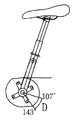
- US 5,549,314 has a simple circular trajectory with a constant value from 107 degrees to 143 degrees with respect to the shortest side as shown in Fig. 8a, and the crank has approximately the shortest side and about 18 degrees so that the position of the saddle when the chain is in contact with the shortest side.
- the crank is located at the point where the position of the crank and the crank coincide.
- crank position of US Pat. No. 5,549,314 is a mathematical driving dead center concept of the hip joint rather than a human driving dead center concept consisting of hip joint, knee joint, ankle joint, and the like.
- the configuration of 107 degrees adds the driving inertia of about 20 degrees to the angle and the maximum output point of the angle of less than 90 degrees, which is the characteristic of the general angle of the seat tube 18 degrees and tangential.
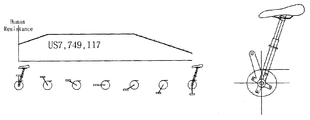
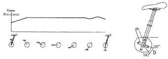
- US 7,749,117 is a symmetrical elliptical gear as shown in Fig. 9b, and the concept of correct human driving dead center which is the center of the knee joint as shown in Fig. 6a is set so that the dead point where the chain is located is 30-45 degrees with the saddle. Place it at ⁇ 130 degrees.
- the position of the longest side of the US7,749,117, the longest side of the saddle and 120 ⁇ 130 degrees, the position of the longest side of the real maximum output section of the human body applying acceleration and inertia in the present invention is much less than the saddle and 165 degrees, this
- the OCP system to overcome is to acknowledge the limitation of symmetric gear.
- the saddle is intended to maintain the body's bodily sensitization resistance from 11 to 6 o'clock in a general bicycle around 18 degrees.
- the present invention has been made in order to solve the above problems, the shape of the ellipse gear is determined by the combination of two ellipses and straight lines close to the vertical, while the distance between the crank shaft and the chain away from the force is greatly In order to reduce the distance between the crankshaft and the chain, it is possible to increase the driving efficiency but to provide smooth driving, easy to design, and to provide an asymmetric elliptical gear that reflects the principles of ergonomics. .
- the longest side and the shortest side angle may be less than 90 degrees
- the first ellipse of the angle b is set by the angle a.
- the longest side and the shortest side are difficult to exceed 120 degrees
- a second ellipse perpendicular to the first ellipse is created at a similar angle.
- the shortest side angle can easily exceed 120 degrees.
- the asymmetric elliptical chain gear according to the present invention includes a first ellipse in which a long axis is located on an X axis of a vertical coordinate system and a short axis is located on a Y axis, and a first straight line perpendicular to the short axis and intersecting the first ellipse ( 3) and the first inflection point (A, A ') which is on the first straight line and is located at a point that makes a constant angle (a) clockwise with respect to the short axis, and the constant angle clockwise at the long axis ( b) a shape is formed by a combination of second ellipses contacting the elliptic contact points (B, B ') on the first ellipse located at a point forming the second ellipse point (C), which is an intersection point of the first straight line and the first ellipse.
- the shape is formed by a combination of one ellipse section.
- the angle (c) formed by the second inflection point (C, C ') and the short axis may be designed not to be larger than the angle (a) between the first inflection point (A, A') and the short axis.
- the larger the angle c is the higher the resistance of the starting point of motion is.
- the lower angle c is, as shown in FIG. 11A, the lower the resistance of the starting point of exercise is.
- the angle a may be characterized in that it is 10 to 35 degrees, lowering the axis length angle a in Figure 10a to create an ellipse parallel to the similar angle and the angle between the longest side and the shortest side is less than 90 degrees 10b can be made in contact with the first ellipse of the angle b by setting the angle a as shown in Figure 10b, wherein the angle of the longest side and the shortest side is difficult to exceed 120 degrees, if the angle a is large as shown in Figure 10c A second ellipse perpendicular to the ellipse is formed at a similar angle, and the longest side and the shortest side angle can easily exceed 120 degrees.
- the angle b may be characterized in that it is 0 to 15 degrees, in the case that b is 0 in Figure 11b occurs a phenomenon that the body resistance decreases instantaneously, the long and short side angle is wider and the larger the angle b is the resistance The increase in congestion intervals is high and the long and short angles are narrowed.
- the gear interdental of the asymmetrical elliptical chain gear according to the present invention may be characterized in that the wide and narrow form is repeated.
- the index groove may be formed in a wide area of the gear tooth of the asymmetric elliptical gear.
- At least one clasp rivet may be coupled to a side portion adjacent to a gear tooth far from a center of the asymmetrical elliptical chain gear.
- Asymmetrical elliptical chain gear according to the present invention may be characterized in that the guard frame having a certain thickness is further coupled to one side of the asymmetric elliptic gear.
- the present invention overcomes the inefficiency of the symmetrical elliptic gear and maximizes the efficiency of the elliptical gear in consideration of the special characteristics such as the movement characteristics of the human body and the dancing driving and the angular acceleration of the crank, and the ineffective section according to the rotational position of the elliptical gear. At the same time, it has the effect of overcoming the problem of the narrow shift section of the symmetric elliptical gear.
- the NC machining is possible by providing a design standard of the asymmetrical elliptical chain gear, and has the advantage of facilitating the design of various elliptical gears suitable for the use of bicycles.
- each a, b, c should be organically applicable to the environment of use of the bicycle, and long and short side angles can be applied within the range of 115 ⁇ 135 degrees.
- the present invention can provide various asymmetric elliptical gears according to the use environment within a certain range of long and short side angles.
- FIG. 1 is a front view when the asymmetrical elliptical chain gear is coupled to a crank according to an embodiment of the present invention.
- Figure 2 is a front view when the asymmetrical elliptical chain gear is mounted according to an embodiment of the present invention.
- Figure 3 is a front view of an asymmetrical elliptical chain gear according to one embodiment of the present invention.
- Figure 4 is a front view of the guard frame of the asymmetrical elliptical chain gear in accordance with one embodiment of the present invention.
- FIG. 5 is an explanatory view for determining the shape of an asymmetrical elliptical chain gear according to an embodiment of the present invention.
- 6A to 6F are operation explanatory diagrams for explaining the dynamic relationship according to the rotation of the chain gear.
- Figure 7 is a further explanatory view for determining the shape of the asymmetrical elliptical chain gear according to an embodiment of the present invention.
- 8a to 8c are explanatory diagrams for explaining the dynamics of the rotation of the patent US 5,549,314.
- 9A to 9D are explanatory views for explaining the body resistance according to the rotation of the chain gear in the present invention and patents US5,549,314 and US Pat. No. 7,749,117.
- 10A to 10C are explanatory views of the basic requirements of the first ellipse and the second ellipse of the present invention.
- 11A to 11C are explanatory diagrams for explaining the body resistance according to the input of various elements of the present invention.
- FIG. 1 to 2 are front views when the asymmetrical elliptical chain gear 10 is mounted according to the preferred embodiment of the present invention
- FIG. 5 is a shape of the asymmetrical elliptical chain gear 10 according to the present invention. It is explanatory drawing to say.
- the asymmetrical elliptical chain gear 10 includes a first ellipse 1 having a long axis located on an X axis of a vertical coordinate system and a short axis located on a Y axis, and the short axis.
- a second ellipse 2 which contacts the elliptic contact point B, B 'on the first ellipse 1 positioned at a point passing through the first inflection point A and A' and forming a constant angle b in the clockwise direction from the long axis;
- the shape is formed by the combination of), the straight section (I) from the second inflection point (C) which is the intersection of the first straight line 3 and the first ellipse (1) and the first inflection point (A), and the A combination of a second ellipse section (J) from the first inflection point (A) to the elliptic contact point (B) and a first elliptic section (K) from the elliptic contact point (B) to the second inflection point (C ') shape It
- the vertical coordinate system is introduced for convenience to clearly explain the principle of determining the shape of the asymmetrical elliptical chain gear according to the present invention.
- all of the asymmetrical elliptical chain gears having the same or similar shape are the rights of the present invention. Will belong to the range.
- the term "elliptical shape" is a concept including a shape close to the ellipse and does not mean a mathematical ellipse.
- the eccentricity of the first ellipse 1 is not limited, but is preferably determined between about 1.05 and 1.25. If the eccentricity is too close to 1, there is no performance difference with the circular gear, and if the eccentricity is too large, shifting is difficult and a runny problem may occur during driving.
- the first straight line 3 is determined to be parallel to the long axis or perpendicular to the short axis and the distance H from the origin is less than or equal to the length d1 of the short side.
- the first straight line 3 is determined at a point where the distance from the origin is close to the length d1 of the short side so that the straight section of the elliptical gear is not too long.
- the intersection of the straight line 3 and the first ellipse 1 is defined as the second inflection point C.
- the first inflection point A is defined on the first straight line 3 and forms a constant angle a in a clockwise direction about the short axis and the origin. At this time, each a is preferably determined between 10 degrees to 35 degrees. If the angle a is too large, the straight section of the elliptical gear becomes too long and the shape of the elliptical gear is greatly distorted. If the angle a is too small, the difference is not different from that of the symmetric elliptic gear.
- An elliptical contact point B defines a point that forms a constant angle b in the clockwise direction with the long axis or the X axis and is positioned on the first ellipse 1. It is preferable to determine each b between 0 degrees and 20 degrees.
- the second ellipse 2 passing through the first inflection point A and contacting the first ellipse 1 at the elliptic contact point B is determined.
- the first ellipse 1, the second ellipse 2, and the first straight line 3 are determined in this way, as illustrated in FIG. 5, a pair of first to second inflection points C and C ′ is determined.
- the shape of is determined.
- the angle c formed by the second inflection point C and C 'and the short axis not be greater than the angle a formed by the first inflection points A and A' and short axis.
- the gear interdental of the asymmetrical elliptical chain gear 10 according to the present invention is preferably formed by repeating a wide and narrow shape.
- the force acting between the chain gear and the chain is not constant. Therefore, it is preferable to increase the closeness of the chain gear and the chain by repeating the wide and narrow shape between the gears.
- the first elliptic section and the second elliptic section of the asymmetric elliptical gear is to form an index groove 12 in a wider of the gear interval so that the chain can be smoothly shifted by the chain gear smoothly shifted. desirable.
- the asymmetrical elliptical chain gear 10 may be characterized in that at least one clasp rivet 13 is coupled to a side portion adjacent to a gear tooth far from the center of the asymmetrical elliptical chain gear. .
- Clasp 13 is to help the chain is caught naturally shifting when shifting. It is preferable to engage the clasp rivet 13 with a focus on a distance far from the center of the chain gear which is likely to not shift smoothly.
- the clasp rivets are formed in a wide interdental position.
- Asymmetrical elliptical chain gear according to the present invention may be characterized in that the guard frame 20 having a certain thickness is further coupled to one side of the asymmetric elliptical gear.
- the guard frame 20 serves to reinforce the strength of the chain gear and prevent the chain from being pinched between the chain gears.
- 6A to 6F are operational explanatory diagrams explaining the dynamic relationship according to the change of the position of the chain gear.
- FIG. 6a shows an angle between the crank arm 30 and the seat tube 40 when the chain is in contact with the shortest side, and forms a starting point of motion.
- the chain is placed in the straight section of the chain gear, or the distance between the chain and the crankshaft is shortest.
- the pedal is hard to apply, so the chain is on the shortest side so that you can drive the bike with less force.
- Figure 6b shows a state in which the angle between the arm of the crank and the seat tube is about 90 degrees. At this time, since the state is capable of applying a relatively strong force to the pedal ergonomically, the distance between the chain and the crankshaft is further accelerated and accelerated than in the state shown in FIG.
- FIG. 6C shows the crank arm almost horizontal to the ground. At this point, the acceleration becomes more active than the point shown in Fig. 6b, and the state can apply the strongest force to the pedal. The distance between the chain and the crankshaft is greater than the state shown in FIG. 6B.
- 6D is a state in which the chain gear and the crank arm are rotated more than the state shown in FIG. 6C.
- the force exerted on the pedal becomes weaker as you pass this point.
- the maximum force on the pedal is not the point, but given the increased inertia due to acceleration during the process described above, the chain is the point of greatest resistance and the saddle angle is 135-170 degrees. Therefore, the distance between the crankshaft and the chain is at this point maximum (h), and after this point the distance between the chain and the crankshaft becomes closer.
- the bicycle asymmetric elliptical chain gear according to the present invention is designed in consideration of both the magnitude of the force applied to the pedal and the angular acceleration of the crank and the driving inertia of the bicycle. It is to output power and at the same time allow smooth driving.
Abstract
According to the present invention, an asymmetric elliptical chain gear (10) is characterized by having a shape formed by a combination of: a first ellipse (1) the major axis of which is located on the X-axis of a vertical coordinate system and the minor axis of which is located on the Y-axis of the vertical coordinate system; a first straight line (3) which is perpendicular to the minor axis, and which intersects the first ellipse (1); and a second ellipse (2) which exists on the first straight line (3) and which passes first inflection points (A, A') that form a fixed angle (a) with respect to the minor axis in the clockwise direction, and which contacts ellipse contact points (B, B') on the first ellipse (1) that are located at points forming a fixed angle (b) in the clockwise direction. The asymmetric elliptical chain gear (10) of the present invention has a shape formed by a combination of a straight line section ranging from a second reflection point (C), which is a cross point between the first straight line (3) and the first ellipse (1), to the first inflection point (A); a second ellipse section ranging from the first inflection point (A) to the ellipse contact point (B); and a first ellipse section ranging from the ellipse contact point (B) to the second inflection point (C').
Description
본 발명은 자전거의 비대칭 타원형상 체인기어에 관한 것으로, 크랭크의 위치에 따라 인체에 의해 페달에 가해지는 힘이 달라지는 것을 감안하여 페달에 가해지는 힘이 커지는 구간에서는 크랭크축과 체인과의 거리를 멀어지게 하여 자전거의 가속을 높이고, 페달에 가해지는 힘이 작아지는 구간에서는 크랭크축과 체인과의 거리를 줄게 하여 적은 힘으로도 크랭크를 회전할 수 있도록 함으로써, 궁극적으로 자전거의 구동 출력과 주행 효율을 향상시키며 인체 저항감의 일관성을 높이는 비대칭 타원형상 체인기어에 관한 것이다. The present invention relates to an asymmetrical elliptical chain gear of a bicycle. In consideration of the force applied to the pedal by the human body according to the position of the crank, the distance between the crankshaft and the chain is increased in a section in which the force applied to the pedal is increased. By increasing the acceleration of the bicycle and reducing the distance between the crankshaft and the chain in the section where the force applied to the pedal becomes smaller, the crank can be rotated with less force, ultimately improving the driving power and driving efficiency of the bicycle. It relates to an asymmetrical elliptical chain gear that improves the consistency of the body resistance.
일반적인 체인기어(또는 스프라켓)의 형상은 원형이다. 원형의 체인기어는 제작이 쉬워 통상적으로 가장 많이 활용된다. 사람이 자전거를 타고 주행하는 동안 페달에 가해지는 힘은 크랭크 암의 위치에 따라 달라진다. 즉 체인이 최단변에 접할 때 크랭크 암이 안장이 결합된 시트튜브와 30~45도에 이르면 인체 역학적으로 페달에 가하는 힘이 극히 줄어들게 되고, 크랭크 암이 시트튜브와 이루는 각이 165도 전후에서 자전거의 주행관성과 크랭크의 각가속도 그리고 인체역학이 결합되어 가장 큰 힘을 안출하는 최장변이 위치한다. 이와 같은 인체 역학적인 원리가 원형의 체인기어에는 전혀 고려되지 않아 자전거의 주행 효율을 떨어뜨리게 된다. The shape of a typical chain gear (or sprocket) is circular. Circular chain gears are easy to manufacture and are most commonly used. The force exerted on the pedals while a person rides a bicycle depends on the position of the crank arm. In other words, when the chain is in contact with the shortest side, when the crank arm reaches 30-45 degrees with the seat tube combined with the saddle, the force applied to the pedal is extremely reduced, and the angle between the crank arm and the seat tube is about 165 degrees. The longest side where the driving inertia of the crank, the angular acceleration of the crank and the human body dynamics are combined to produce the greatest force is located. This principle of ergonomics is not considered in the circular chain gear at all, which reduces the driving efficiency of the bicycle.
상기와 같은 문제점을 해결하기 위하여 여러 형태의 타원 형상의 체인기어가 제작되어 왔다. 현재까지 알려진 타원기어는 크게 대칭형 타원기어와 비대칭형 타원기어로 나뉜다. 현재 개시된 대칭형 타원기어의 경우 타원기어의 제작이 용이한 장점이 있으나, 힘이 크게 가해져야 하는 일부 구간에서 오히려 크랭크 축과 체인과의 간격이 줄어들어 주행 효율이 낮아지고 울렁거림이 발생하며 기어변속이 원활하지 않은 단점이 있어 왔다. 기존의 비대칭 타원기어의 경우에는 대칭형 타원기어에 비해 이러한 문제점을 다소 해결하는 측면이 있으나 제작이 용이하지 않아 제작 단가가 높아지는 단점을 가지며, 인체 역학적인 원리가 정확히 반영되지 않는 종래의 문제점을 여전히 가지고 있다. In order to solve the above problems, various types of elliptical chain gears have been manufactured. Elliptical gears known to date are largely divided into symmetric elliptical gears and asymmetric elliptical gears. The presently disclosed symmetric elliptic gear has the advantage of easy manufacturing of elliptical gears, but in some sections where a large force should be applied, the distance between the crankshaft and the chain is reduced, resulting in low running efficiency, rumble, and gear shifting. There have been drawbacks that are not smooth. Conventional asymmetric elliptical gears have some aspects of solving these problems compared to symmetrical elliptical gears, but they are not easy to manufacture and have a disadvantage of increasing manufacturing cost, and still have the conventional problems in which the principles of ergonomics are not accurately reflected. have.
US5,549,314는 도8a와 같이 최단변을 기준으로 각도 107도에서 143도까지 상수값인 단순원호궤적을 갖고, 크랭크는 대략 최단변과 18도 정도를 이루어져 체인이 최단변에 접할 때 안장의 위치와 크랭크의 위치가 일치하는 지점에 크랭크가 위치한다.US 5,549,314 has a simple circular trajectory with a constant value from 107 degrees to 143 degrees with respect to the shortest side as shown in Fig. 8a, and the crank has approximately the shortest side and about 18 degrees so that the position of the saddle when the chain is in contact with the shortest side. The crank is located at the point where the position of the crank and the crank coincide.
US5,549,314의 크랭크 위치는 고관절, 슬관절, 족관절 등으로 구성된 인체구동사점 개념이 아닌 고관절 중심인 수학적 구동사점 개념을 적용시킨 것이어서, 도8a는 사점위치이고 도8b는 최대출력구간인 최장변을 이루도록 구성되었고, 107도의 구성은 시트튜브의 일반각도 18도와 접선의 특성인 90도 미만의 각도와 최대출력 지점에, 20도 전후를 추가하는 주행관성을 더한 것이다.The crank position of US Pat. No. 5,549,314 is a mathematical driving dead center concept of the hip joint rather than a human driving dead center concept consisting of hip joint, knee joint, ankle joint, and the like. The configuration of 107 degrees adds the driving inertia of about 20 degrees to the angle and the maximum output point of the angle of less than 90 degrees, which is the characteristic of the general angle of the seat tube 18 degrees and tangential.
US7,749,117은 도9b와 같이 대칭타원기어로써 도6a와 같은 슬관절 중심인 올바른 인체구동사점 개념을 넣어서 체인이 최단변이 위치하는 사점을 안장과 30~45도를 이루도록 하고 최대출력구간은 안장과 120~130도에 위치하도록 한다.US 7,749,117 is a symmetrical elliptical gear as shown in Fig. 9b, and the concept of correct human driving dead center which is the center of the knee joint as shown in Fig. 6a is set so that the dead point where the chain is located is 30-45 degrees with the saddle. Place it at ~ 130 degrees.
US7,749,117의 최대출력구간인 최장변이 안장과 120~130도에 위치한 것은, 본 발명에서 가속도와 관성을 적용한 실질 인체최대출력구간인 최장변의 위치가 안장과 165도에 훨씬 못 미치는 수준이고, 이를 극복하기 위한 OCP시스템은 대칭기어의 한계성을 오히려 인정하는 것이 된다. The position of the longest side of the US7,749,117, the longest side of the saddle and 120 ~ 130 degrees, the position of the longest side of the real maximum output section of the human body applying acceleration and inertia in the present invention is much less than the saddle and 165 degrees, this The OCP system to overcome is to acknowledge the limitation of symmetric gear.
도9d와 같이 US5,549,314 또한 크랭크각도를 인체구동사점을 적용한다고 해도 최장변 시작점과 안장은 140도 전후에 그치게 되며, 체인이 최장변에 진입 후 h는 체감해야 하는데 상수값 D구간으로 도10b와 같이 인체저항감이 순간적 손실이 되고, 크랭크 운동하사점이 발생할 만큼 인체저항값은 순간 상승하게 된다.As shown in FIG. 9D, even when the human body driving dead center is applied to the crank angle, the longest side start point and the saddle stop at about 140 degrees, and after the chain enters the longest side, h must be felt. As shown in the drawing, the body's resistance is instantaneously lost, and the body's resistance is momentarily raised so that the crank motion dead center occurs.
본 발명은 US5,549,314의 잘못된 사점위치와 인체운동성에 존재하지 않는 크랭크중심에서의 원호궤적인 상수값이 없도록 하고, US7,749,117에서 부족한 체증구간인 장·단변 각도 90도가 아닌 135도에 육박하도록 해서 도9a와 같이 안장이 18도 전후의 일반자전거에서 11시부터 6시까지 인체의 체감저항을 일정하게 유지하는 것을 목적으로 한다.In the present invention, there is no arc dead center position of US5,549,314 and a circular arc trajectory constant value in the crank center which does not exist in human motility, and close to 135 degrees instead of 90 degrees of long and short sides, which is a lacking section in US 7,749,117. Thus, as shown in Fig. 9a, the saddle is intended to maintain the body's bodily sensitization resistance from 11 to 6 o'clock in a general bicycle around 18 degrees.
본 발명은 상기의 문제점을 해결하기 위하여 안출된 것으로서, 수직에 가까운 두 타원과 직선의 조합으로 타원기어의 형상을 결정하되, 힘이 크게 가해지는 구간에서는 크랭크 축과 체인과의 거리를 멀어지게 하고, 힘이 작게 가해지는 구간에서는 크랭크 축과 체인과의 거리를 줄어들게 하여 주행효율을 높이되 부드러운 주행이 가능하고, 설계가 용이하며 인체역학의 원리가 최대한 반영된 비대칭 타원기어를 제공함에 그 목적이 있다. The present invention has been made in order to solve the above problems, the shape of the ellipse gear is determined by the combination of two ellipses and straight lines close to the vertical, while the distance between the crank shaft and the chain away from the force is greatly In order to reduce the distance between the crankshaft and the chain, it is possible to increase the driving efficiency but to provide smooth driving, easy to design, and to provide an asymmetric elliptical gear that reflects the principles of ergonomics. .
도10a에서와 같이 축길이 각도a를 낮추면 유사각도로 평행하는 타원이 만들어지고 최장변과 최단변의 각도는 90도 미만이 될 수 있으며, 도10b와 같이 각도a의 설정으로 각도b의 제1타원과 접하는 원이 만들어질 수 있고 이때 최장변과 최단변의 각도는 120도를 넘기기 어렵고, 도10c와 같이 각도a가 클 경우 제1타원에 유사각도로 수직의 제2타원이 만들어지며 이때 최장변과 최단변의 각도는 120도를 쉽게 넘길 수 있게 된다.As shown in FIG. 10A, when the axis length angle a is lowered, an ellipse parallel to the similar angle is created, and the longest side and the shortest side angle may be less than 90 degrees, and as shown in FIG. 10B, the first ellipse of the angle b is set by the angle a. The longest side and the shortest side are difficult to exceed 120 degrees, and when the angle a is large as shown in FIG. 10c, a second ellipse perpendicular to the first ellipse is created at a similar angle. The shortest side angle can easily exceed 120 degrees.
본 발명에 따른 비대칭 타원형상 체인기어는, 수직좌표계의 X축 상에 장축이 위치하고 Y축 상에 단축이 위치하는 제1타원과, 상기 단축에 수직하고 상기 제1타원과 교차하는 제1직선(3)과, 상기 제1직선 상에 존재하고 상기 단축에 대해 시계방향으로 일정한 각(a)을 이루는 지점에 위치하는 제1변곡점(A, A')을 지나고 상기 장축에서 시계방향으로 일정한 각(b)을 이루는 지점에 위치하는 제1타원상의 타원접점(B, B')에 접하는 제2타원의 조합으로 형상이 이루어지되, 상기 제1직선과 제1타원의 교차점인 제2변곡점(C)에서 상기 제1변곡점에 이르는 직선구간과, 상기 제1변곡점(A)에서 상기 타원접점(B)에 이르는 제2타원구간 및 상기 타원접점(B)에서 상기 제2변곡점(C')에 이르는 제1타원구간의 조합으로 형상이 이루어지는 것을 특징으로 한다. The asymmetric elliptical chain gear according to the present invention includes a first ellipse in which a long axis is located on an X axis of a vertical coordinate system and a short axis is located on a Y axis, and a first straight line perpendicular to the short axis and intersecting the first ellipse ( 3) and the first inflection point (A, A ') which is on the first straight line and is located at a point that makes a constant angle (a) clockwise with respect to the short axis, and the constant angle clockwise at the long axis ( b) a shape is formed by a combination of second ellipses contacting the elliptic contact points (B, B ') on the first ellipse located at a point forming the second ellipse point (C), which is an intersection point of the first straight line and the first ellipse. A straight line extending from the first inflection point to a second elliptic point from the first inflection point (A) to the elliptic contact point (B) and a second inflection point (C ') from the elliptic contact point (B). The shape is formed by a combination of one ellipse section.
이 경우, 상기 제2변곡점(C, C')과 단축이 이루는 각(c)는 상기 제1변곡점(A, A')과 단축이 이루는 각(a)보다 크지 않도록 설계되는 것을 특징으로 할 수 있으며, 도11c에서 각 c가 클수록 운동시작점의 저항감은 높아지고 도11a에서와 같이 각 c가 작을수록 운동시작점의 저항감은 낮아진다.In this case, the angle (c) formed by the second inflection point (C, C ') and the short axis may be designed not to be larger than the angle (a) between the first inflection point (A, A') and the short axis. In FIG. 11C, the larger the angle c is, the higher the resistance of the starting point of motion is. As the lower angle c is, as shown in FIG. 11A, the lower the resistance of the starting point of exercise is.
또한, 상기 각 a는 10도 내지 35도 인 것을 특징으로 할 수 있으며, 도10a에서의 축길이 각도a를 낮추면 유사각도로 평행하는 타원이 만들어지고 최장변과 최단변의 각도는 90도미만이 될 수 있으며 도10b와 같이 각도a의 설정으로 각도b의 제1타원과 접하는 원이 만들어질 수 있고 이때 최장변과 최단변의 각도는 120도를 넘기기 어렵고, 도10c와 같이 각도a가 클 경우 제1타원에 유사각도로 수직의 제2타원이 만들어지며 이때 최장변과 최단변의 각도는 120도를 쉽게 넘길 수 있게 된다.In addition, the angle a may be characterized in that it is 10 to 35 degrees, lowering the axis length angle a in Figure 10a to create an ellipse parallel to the similar angle and the angle between the longest side and the shortest side is less than 90 degrees 10b can be made in contact with the first ellipse of the angle b by setting the angle a as shown in Figure 10b, wherein the angle of the longest side and the shortest side is difficult to exceed 120 degrees, if the angle a is large as shown in Figure 10c A second ellipse perpendicular to the ellipse is formed at a similar angle, and the longest side and the shortest side angle can easily exceed 120 degrees.
또한, 상기 각 b는 0도 내지 15도인 것을 특징으로 할 수 있으며, 도11b에서 각 b가 0일 경우 인체저항감이 순간 감소하는 현상이 발생하며 장·단변각도는 넓어지고 각 b가 클수록 저항의 체증구간의 증가는 높아지고 장·단변각도는 좁아진다.In addition, the angle b may be characterized in that it is 0 to 15 degrees, in the case that b is 0 in Figure 11b occurs a phenomenon that the body resistance decreases instantaneously, the long and short side angle is wider and the larger the angle b is the resistance The increase in congestion intervals is high and the long and short angles are narrowed.
본 발명에 따른 비대칭 타원형상 체인기어의 기어 치간은 넓고 좁은 형태가 반복되어 형성되는 것을 특징으로 할 수 있다. 이 경우, 상기 비대칭 타원기어의 기어 치간 중 넓은 곳에 인덱스홈이 형성되는 것을 특징으로 할 수 있다. The gear interdental of the asymmetrical elliptical chain gear according to the present invention may be characterized in that the wide and narrow form is repeated. In this case, the index groove may be formed in a wide area of the gear tooth of the asymmetric elliptical gear.
또한, 상기 비대칭 타원형상 체인기어의 중심에서 거리가 먼 곳의 기어치와 인접한 측면부에 적어도 하나 이상의 걸쇠리벳이 결합되는 것을 특징으로 할 수 있다. In addition, at least one clasp rivet may be coupled to a side portion adjacent to a gear tooth far from a center of the asymmetrical elliptical chain gear.
본 발명에 따른 비대칭 타원형상 체인기어는 상기 비대칭 타원기어의 일측면에는 일정한 두께를 가지는 가드프레임이 더 결합되는 것을 특징으로 할 수 있다. Asymmetrical elliptical chain gear according to the present invention may be characterized in that the guard frame having a certain thickness is further coupled to one side of the asymmetric elliptic gear.
본 발명은 대칭형 타원기어의 비효율성을 극복하고 인체의 운동 특성과 댄싱 주행과 같은 특수상황 및 주행관성과 크랭크의 각가속도를 고려하여 타원기어의 효율을 극대화 하였으며, 타원기어의 회전위치에 따른 비효율구간을 최소화함과 동시에 대칭형 타원기어가 가지는 좁은 변속구간의 문제를 극복하는 효과가 있다. The present invention overcomes the inefficiency of the symmetrical elliptic gear and maximizes the efficiency of the elliptical gear in consideration of the special characteristics such as the movement characteristics of the human body and the dancing driving and the angular acceleration of the crank, and the ineffective section according to the rotational position of the elliptical gear. At the same time, it has the effect of overcoming the problem of the narrow shift section of the symmetric elliptical gear.
또한, 비대칭 타원형상 체인기어의 설계기준을 제공하여 NC 가공이 가능하고, 자전거의 활용에 적합한 다양한 형태의 타원기어의 설계가 용이하도록 하는 장점을 가진다.In addition, the NC machining is possible by providing a design standard of the asymmetrical elliptical chain gear, and has the advantage of facilitating the design of various elliptical gears suitable for the use of bicycles.
도11a과 같이 본 발명의 일반적 각 a와 각 b의 설정일 경우와 다르게, 도11b와 같이 각 b가 0도일 경우 인체저항감은 순간 감소구간이 존재하는데, 이러한 경우는 산악자전거의 비포장 오르막주행 용도로 적용되어야 하고, 도11c와 같이 각 c가 클 경우는 클릿페달을 사용하는 경우에 반대편 페달을 당기는 힘이 추가되는 사례에 적용된다. 그러므로 각 a, b, c는 자전거의 사용환경에 유기적으로 적용할 수 있는 수준이어야 하고 장·단변각도가 115~135도를 벗어나지 않는 범위에서 적용가능하다.Unlike the case of setting general angles a and b of the present invention as shown in FIG. 11A, when each b is 0 degrees as shown in FIG. 11B, there is an instantaneous decrease in body resistance, in this case, for an unpaved uphill driving of a mountain bike. If each c is large as shown in Fig. 11C, it is applied to the case in which the force of pulling the opposite pedal is added when the cleat pedal is used. Therefore, each a, b, c should be organically applicable to the environment of use of the bicycle, and long and short side angles can be applied within the range of 115 ~ 135 degrees.
위와 같이 본 발명은 장·단변각도의 일정범위 안에서 사용환경에 따른 다양한 비대칭타원기어를 제공할 수 있는 것이다.As described above, the present invention can provide various asymmetric elliptical gears according to the use environment within a certain range of long and short side angles.
도1은 본 발명의 일 실시예에 따른 비대칭 타원형상 체인기어가 크랭크에 결합된 경우의 정면도. 1 is a front view when the asymmetrical elliptical chain gear is coupled to a crank according to an embodiment of the present invention.
도2는 본 발명의 일 실시예에 따른 비대칭 타원형상 체인기어가 장착된 경우의 정면도. Figure 2 is a front view when the asymmetrical elliptical chain gear is mounted according to an embodiment of the present invention.
도3은 본 발명의 일 실시예에 따른 비대칭 타원형상 체인기어의 정면도. Figure 3 is a front view of an asymmetrical elliptical chain gear according to one embodiment of the present invention.
도4는 본 발명의 일 실시예에 따른 비대칭 타원형상 체인기어의 가드프레임의 정면도. Figure 4 is a front view of the guard frame of the asymmetrical elliptical chain gear in accordance with one embodiment of the present invention.
도5는 본 발명의 일 실시예에 따른 비대칭 타원형상 체인기어의 형상을 결정하는 설명도. 5 is an explanatory view for determining the shape of an asymmetrical elliptical chain gear according to an embodiment of the present invention.
도6a 내지 도6f는 체인기어의 회전에 따른 역학관계를 설명하기 위한 작동설명도. 6A to 6F are operation explanatory diagrams for explaining the dynamic relationship according to the rotation of the chain gear.
도7은 본 발명의 일 실시예에 따른 비대칭 타원형상 체인기어의 형상을 결정하는 추가 설명도.Figure 7 is a further explanatory view for determining the shape of the asymmetrical elliptical chain gear according to an embodiment of the present invention.
도8a 내지 도8c는 특허 US5,549,314의 회전에 따른 역학관계를 설명하기 위한 작동 설명도.8a to 8c are explanatory diagrams for explaining the dynamics of the rotation of the patent US 5,549,314.
도9a 내지 도9d는 본 발명과 특허 US5,549,314 그리고 특허 US7,749,117에서 체인기어의 회전에 따른 인체저항감을 설명하기 위한 설명도.9A to 9D are explanatory views for explaining the body resistance according to the rotation of the chain gear in the present invention and patents US5,549,314 and US Pat. No. 7,749,117.
도10a 내지 도10c는 본 발명의 제1타원과 제2타원의 기본요건에 관한 설명도.10A to 10C are explanatory views of the basic requirements of the first ellipse and the second ellipse of the present invention.
도11a 내지 도11c는 본 발명의 다양한 요소 투입에 따른 인체저항감을 설명하기 위한 설명도.11A to 11C are explanatory diagrams for explaining the body resistance according to the input of various elements of the present invention.
* 부호의 설명* Explanation of the sign
1 : 제1타원 2 : 제2타원 1: first ellipse 2: second ellipse
3 : 제1직선 10 : 비대칭 타원형상 체인기어 3: first straight line 10: asymmetrical elliptical chain gear
12 : 인덱스 홈 13 : 걸쇠리벳 12: index groove 13: clasp rivet
20 : 가드프레임 30 : 크랭크 암 20: guard frame 30: crank arm
40 : 시트튜브 40: seat tube
A, A' : 제1변곡점 B, B' : 타원접점A, A ': first inflection point B, B': elliptic contact
C, C' : 제2변곡점C, C ': second inflection point
I : 직선구간 J : 제2타원구간 I: Straight section J: Second ellipse section
K : 제1타원구간 K: first ellipse section
이하, 본 발명이 속하는 기술분야에서 통상의 지식을 가진 자가 용이하게 실시할 수 있도록 본 발명의 실시예에 대하여 첨부한 도면을 참고로 하여 상세히 설명한다. 그러나 본 발명은 여러 가지 상이한 형태로 구현될 수 있으며 여기에서 말하는 실시예에 한정되지 않는다. Hereinafter, exemplary embodiments of the present invention will be described in detail with reference to the accompanying drawings so that those skilled in the art may easily implement the present invention. As those skilled in the art would realize, the described embodiments may be modified in various different ways, all without departing from the spirit or scope of the present invention.
이하, 도1 내지 도6을 참조하여 본 발명에 따른 비대칭 타원형상 체인기어(10)에 관한 바람직한 실시예를 설명한다. 1 to 6, a preferred embodiment of the asymmetrical elliptical chain gear 10 according to the present invention will be described.
도1 내지 도2는 본 발명의 바람직한 일 실시예에 따른 비대칭 타원형상 체인기어(10)가 장착된 경우의 정면도이고, 도5는 본 발명에 따른 비대칭 타원형상 체인기어(10)의 형상을 결정하는 설명도이다. 1 to 2 are front views when the asymmetrical elliptical chain gear 10 is mounted according to the preferred embodiment of the present invention, and FIG. 5 is a shape of the asymmetrical elliptical chain gear 10 according to the present invention. It is explanatory drawing to say.
도5를 참조하여 설명하면, 본 발명에 따른 비대칭 타원형상 체인기어(10)는, 수직좌표계의 X축 상에 장축이 위치하고 Y축 상에 단축이 위치하는 제1타원(1)과, 상기 단축에 수직하고 상기 제1타원(1)과 교차하는 제1직선(3)과, 상기 제1직선(3) 상에 존재하고 상기 단축에 대해 시계방향으로 일정한 각(a)을 이루는 지점에 위치하는 제1변곡점(A, A')을 지나고 상기 장축에서 시계방향으로 일정한 각(b)을 이루는 지점에 위치하는 제1타원(1)상의 타원접점(B, B')에 접하는 제2타원(2)의 조합으로 형상이 이루어지되, 상기 제1직선(3)과 제1타원(1)의 교차점인 제2변곡점(C)에서 상기 제1변곡점(A)에 이르는 직선구간(I)과, 상기 제1변곡점(A)에서 상기 타원접점(B)에 이르는 제2타원구간(J) 및 상기 타원접점(B)에서 상기 제2변곡점(C')에 이르는 제1타원구간(K)의 조합으로 형상이 이루어지는 것을 특징으로 한다.Referring to FIG. 5, the asymmetrical elliptical chain gear 10 according to the present invention includes a first ellipse 1 having a long axis located on an X axis of a vertical coordinate system and a short axis located on a Y axis, and the short axis. A first straight line (3) perpendicular to and intersecting the first ellipse (1) and located at a point on the first straight line (3) and at a constant angle (a) clockwise relative to the minor axis; A second ellipse 2 which contacts the elliptic contact point B, B 'on the first ellipse 1 positioned at a point passing through the first inflection point A and A' and forming a constant angle b in the clockwise direction from the long axis; The shape is formed by the combination of), the straight section (I) from the second inflection point (C) which is the intersection of the first straight line 3 and the first ellipse (1) and the first inflection point (A), and the A combination of a second ellipse section (J) from the first inflection point (A) to the elliptic contact point (B) and a first elliptic section (K) from the elliptic contact point (B) to the second inflection point (C ') shape It characterized by comprising.
상기의 수직좌표계는 본 발명에 따른 비대칭 타원형상 체인기어의 형상이 결정되는 원리를 명확하게 설명하기 위해 편의상 도입한 것이며, 결과적으로 동일하거나 유사한 형상을 가지는 비대칭 타원형상 체인기어는 모두 본 발명의 권리범위에 속한다 할 것이다. 또한 상기의 용어 중 "타원형상"은 타원에 가까운 형상을 포함하는 개념이고 수학적인 타원을 의미하는 것은 아니다. The vertical coordinate system is introduced for convenience to clearly explain the principle of determining the shape of the asymmetrical elliptical chain gear according to the present invention. As a result, all of the asymmetrical elliptical chain gears having the same or similar shape are the rights of the present invention. Will belong to the range. In addition, the term "elliptical shape" is a concept including a shape close to the ellipse and does not mean a mathematical ellipse.
도 5를 참조하여 설명하면, 제1타원(1)의 이심률에 제한은 없으나, 약 1.05 내지 1.25의 사이에서 결정되는 것이 바람직하다. 이심률이 지나치게 1에 가까우면 원형기어와 성능적인 차이가 없어지게 되고, 이심률이 지나치게 크면 변속이 어렵고, 주행시 울렁거림 문제가 발생 할 수 있기 때문이다. 제1타원(1)이 결정되면, 장축과 평행 또는 단축과 수직이고 원점과의 거리(H)가 단변의 길이(d1)보다 작거나 같은 제1직선(3)을 결정한다. 타원기어의 직선구간이 지나치게 길어지지 않도록 원점과의 거리가 단변의 길이(d1)에 가까운 지점에서 제1직선(3)을 결정한다. 직선(3)과 제1타원(1)과의 교점을 제2변곡점(C)으로 정의한다. 상기 제1직선(3) 상에 위치하고 단축과 원점을 중심으로 시계방향으로 일정한 각(a)을 이루는 점을 제1변곡점(A)으로 정의한다. 이때 각 a는 10도 내지 35도 사이에서 결정하는 것이 바람직하다. 각 a가 지나치게 커지면 타원기어의 직선구간이 너무 길어짐과 동시에 타원기어의 형상이 크게 왜곡될 수 있고, 각 a가 지나치게 작으면 대칭형 타원기어와 차이가 없어지게 되기 때문이다. 장축 또는 X축과 시계방향으로 일정한 각(b)을 이루고, 제1타원(1)상에 위치하는 점을 타원접점(B)으로 정의한다. 각 b 는 0도 내지 20도의 사이에서 결정하는 것이 바람직하다. Referring to FIG. 5, the eccentricity of the first ellipse 1 is not limited, but is preferably determined between about 1.05 and 1.25. If the eccentricity is too close to 1, there is no performance difference with the circular gear, and if the eccentricity is too large, shifting is difficult and a runny problem may occur during driving. When the first ellipse 1 is determined, the first straight line 3 is determined to be parallel to the long axis or perpendicular to the short axis and the distance H from the origin is less than or equal to the length d1 of the short side. The first straight line 3 is determined at a point where the distance from the origin is close to the length d1 of the short side so that the straight section of the elliptical gear is not too long. The intersection of the straight line 3 and the first ellipse 1 is defined as the second inflection point C. The first inflection point A is defined on the first straight line 3 and forms a constant angle a in a clockwise direction about the short axis and the origin. At this time, each a is preferably determined between 10 degrees to 35 degrees. If the angle a is too large, the straight section of the elliptical gear becomes too long and the shape of the elliptical gear is greatly distorted. If the angle a is too small, the difference is not different from that of the symmetric elliptic gear. An elliptical contact point B defines a point that forms a constant angle b in the clockwise direction with the long axis or the X axis and is positioned on the first ellipse 1. It is preferable to determine each b between 0 degrees and 20 degrees.
상기 제1변곡점(A)을 지나고 타원접점(B)에서 제1타원(1)과 접하는 제2타원(2)을 결정한다. 이렇게 제1타원(1), 제2타원(2) 및 제1직선(3)이 결정되면, 도 5에서 도시된 바와 같이 한 쌍의 제1 내지 제2변곡점(C,C')이 결정되고, 점 C에서 점 A를 연결하는 직선구간(I), 점 A에서 점 B를 연결하는 제2타원구간(J), 점 B에서 점 C'를 연결하는 제1타원구간(K), 다시 점 C'에서 점 A'를 연결하는 직선구간, 점 A'에서 점 B'를 연결하는 제2타원구간 및 점 B'에서 점 C를 연결하는 제1타원구간으로 본 발명에 따른 비대칭 타원형상 체인기어의 형상이 결정된다. The second ellipse 2 passing through the first inflection point A and contacting the first ellipse 1 at the elliptic contact point B is determined. When the first ellipse 1, the second ellipse 2, and the first straight line 3 are determined in this way, as illustrated in FIG. 5, a pair of first to second inflection points C and C ′ is determined. , A straight section (I) connecting point A at point C, a second ellipse section (J) connecting point B at point A, a first ellipse section (K) connecting point C 'at point B, again a point Asymmetrical elliptical chain gear according to the present invention as a straight section connecting point A 'at C', a second ellipse section connecting point B 'at point A' and a first ellipse section connecting point C at point B ' The shape of is determined.
이 경우, 상기 제2변곡점(C, C')과 단축이 이루는 각(c)는 상기 제1변곡점(A, A')과 단축이 이루는 각(a)보다 크지 않도록 설계하는 것이 바람직하다. In this case, it is preferable that the angle c formed by the second inflection point C and C 'and the short axis not be greater than the angle a formed by the first inflection points A and A' and short axis.
본 발명에 따른 비대칭 타원형상 체인기어(10)의 기어 치간은 넓고 좁은 형태가 반복되어 형성되는 것이 바람직하다. 타원형상 체인기어의 경우에는 원형기어와 달리 체인기어와 체인 사이에 작용하는 힘이 일정하지 않으므로, 기어 치간을 넓고 좁은 형태를 반복하여 체인기어와 체인과의 밀착도를 높이는 것이 바람직하다. 이 때, 상기 비대칭 타원기어의 제1타원구간 및 제2타원구간에는 기어 치간 중 넓은 곳에 인덱스홈(12)을 형성하여 체인이 체인기어에 의해 좀더 부드럽게 힘을 받아 자연스럽게 변속이 될 수 있도록 하는 것이 바람직하다. The gear interdental of the asymmetrical elliptical chain gear 10 according to the present invention is preferably formed by repeating a wide and narrow shape. In the case of the elliptical chain gear, unlike the circular gear, the force acting between the chain gear and the chain is not constant. Therefore, it is preferable to increase the closeness of the chain gear and the chain by repeating the wide and narrow shape between the gears. At this time, in the first elliptic section and the second elliptic section of the asymmetric elliptical gear is to form an index groove 12 in a wider of the gear interval so that the chain can be smoothly shifted by the chain gear smoothly shifted. desirable.
본 발명에 따른 비대칭 타원형상 체인기어(10)는 상기 비대칭 타원형상 체인기어의 중심에서 거리가 먼 곳의 기어치와 인접한 측면부에 적어도 하나 이상의 걸쇠리벳(13)이 결합되는 것을 특징으로 할 수 있다. 걸쇠리벳(13)은 변속시 체인이 걸려 자연스럽게 변속이 되는 것을 돕는 역할을 한다. 변속이 원활하지 않을 가능성이 큰 체인기어의 중심에서 거리가 먼 곳에 중점적으로 걸쇠리벳(13)을 결합하는 것이 바람직하다. 또한, 걸쇠리벳은 치간이 넓은 곳에 형성되도록 하는 것이 바람직하다. The asymmetrical elliptical chain gear 10 according to the present invention may be characterized in that at least one clasp rivet 13 is coupled to a side portion adjacent to a gear tooth far from the center of the asymmetrical elliptical chain gear. . Clasp 13 is to help the chain is caught naturally shifting when shifting. It is preferable to engage the clasp rivet 13 with a focus on a distance far from the center of the chain gear which is likely to not shift smoothly. In addition, it is preferable that the clasp rivets are formed in a wide interdental position.
본 발명에 따른 비대칭 타원형상 체인기어는 상기 비대칭 타원기어의 일측면에는 일정한 두께를 가지는 가드프레임(20)이 더 결합되는 것을 특징으로 할 수 있다. 가드프레임(20)은 체인기어의 강도를 보강함과 동시에 체인기어 사이에 체인이 끼지 않도록 하는 역할을 한다. Asymmetrical elliptical chain gear according to the present invention may be characterized in that the guard frame 20 having a certain thickness is further coupled to one side of the asymmetric elliptical gear. The guard frame 20 serves to reinforce the strength of the chain gear and prevent the chain from being pinched between the chain gears.
도 6a 내지 도 6f를 참조하여 본 발명에 따른 비대칭 타원형상 체인기어의 회전에 따른 작동을 설명한다. 6A to 6F, the operation of the asymmetrical elliptical chain gear according to the present invention will be described.
도 6a 내지 도 6f는 체인기어의 위치변화에 따른 역학관계를 설명한 작동설명도이다. 6A to 6F are operational explanatory diagrams explaining the dynamic relationship according to the change of the position of the chain gear.
도 6a는 체인이 최단변에 접할 때 크랭크 암(30)과 시트튜브(40) 사이의 각이 약 30~45도를 이루는 상태이며 운동의 시작점이 된다. 이 상태에서 체인은 체인기어의 직선구간에 놓이거나, 체인과 크랭크 축의 거리가 가장 짧아지는 경우이다. 운동의 시작점에서는 페달에 큰 힘을 가하기 힘들므로 적은 힘으로도 자전거를 구동할 수 있도록 체인이 최단변에 놓이게 된다. FIG. 6a shows an angle between the crank arm 30 and the seat tube 40 when the chain is in contact with the shortest side, and forms a starting point of motion. In this state, the chain is placed in the straight section of the chain gear, or the distance between the chain and the crankshaft is shortest. At the start of the exercise, the pedal is hard to apply, so the chain is on the shortest side so that you can drive the bike with less force.
도 6b는 크랭크의 암과 시트튜브 사이의 각이 약 90도를 이루는 상태를 나타낸다. 이 때에는 인체역학적으로 페달에 상대적으로 강한 힘을 가할 수 있는 상태가 되므로 도 6a에 도시된 상태에서 보다 체인과 크랭크 축과의 거리가 멀어지게 되고 점점 가속된다. Figure 6b shows a state in which the angle between the arm of the crank and the seat tube is about 90 degrees. At this time, since the state is capable of applying a relatively strong force to the pedal ergonomically, the distance between the chain and the crankshaft is further accelerated and accelerated than in the state shown in FIG.
도 6c는 크랭크 암이 지면에 거의 수평한 상태이다. 이 지점에서는 도 6b에 도시된 지점보다 좀 더 가속이 활발해지는 지점이며, 페달에 상대적으로 가장 강한 힘을 가할 수 있는 상태가 된다. 도 6b에 도시된 상태보다 체인과 크랭크 축과의 거리가 더 멀어지는 구간이다. 6C shows the crank arm almost horizontal to the ground. At this point, the acceleration becomes more active than the point shown in Fig. 6b, and the state can apply the strongest force to the pedal. The distance between the chain and the crankshaft is greater than the state shown in FIG. 6B.
도 6d는 도 6c에서 도시된 상태보다 체인기어와 크랭크 암이 더 회전된 상태이다. 페달에 가해지는 힘이 이 시점을 지나면서 점점 약해진다. 페달에 가해지는 힘이 최대인 지점은 아니지만 앞서 설명된 과정 동안 가속에 의해 증가한 관성을 고려하면 체인에 가장 큰 저항력이 걸리는 지점이며 안장과의 각도는 135~170도 수준이 된다. 따라서 이 지점에서 크랭크 축과 체인과의 거리가 최대(h)가 되며 이 지점 이후부터는 체인과 크랭크 축의 거리가 점점 가까워지게 된다. 6D is a state in which the chain gear and the crank arm are rotated more than the state shown in FIG. 6C. The force exerted on the pedal becomes weaker as you pass this point. The maximum force on the pedal is not the point, but given the increased inertia due to acceleration during the process described above, the chain is the point of greatest resistance and the saddle angle is 135-170 degrees. Therefore, the distance between the crankshaft and the chain is at this point maximum (h), and after this point the distance between the chain and the crankshaft becomes closer.
종래의 대칭형 타원기어에 있어서는 이 지점 이전에서 체인과 크랭크 축의 거리가 짧아져 체인에 걸리는 저항력이 크게 줄어들게 되는데 이렇게 되면 주행시 울렁거림 현상이 발생하고 인체에 의해 가해지는 힘을 최대한 가하지 못하게 되어 비효율적인 구동이 생기게 된다. 특히 엉덩이가 시트에서 떨어진 상태에서 주행하는 댄싱 주행의 경우에는 종래의 대칭형 타원기어의 경우 심한 울렁거림 현상이 발생한다. In the conventional symmetrical elliptic gear, the distance between the chain and the crankshaft is shortened before this point, and the resistance to the chain is greatly reduced. Will be produced. In particular, in the case of a dancing run in which the hips run away from the seat, a severe snarl occurs in the conventional symmetric elliptical gear.
도6e에서 도6f로 도시된 상태로 갈수록 페달에 가하는 힘이 크게 줄어들게 되므로 크랭크 축과 체인과의 거리가 급격히 짧아지게 되어 작은 힘으로도 구동이 가능하게 된다. 도9d와 같이 US5,549,314는 체인이 최단변에 접할 때 안장과 크랭크의 각이 30~45도인 경우 원호궤적인 상수값 D구간으로 인해 도10b와 같이 인체저항감 손실이 순간적으로 발생하다가 곧바로 인체의 요구저항이 급격히 증가하는 하사점이 존재할 수 있다. 6e to 6f, the force applied to the pedal is greatly reduced, so that the distance between the crankshaft and the chain is drastically shortened, thereby enabling driving with a small force. As shown in FIG. 9D, US5,549,314 instantaneously causes a loss of human body resistance as shown in FIG. 10B due to the circular arc constant value D section when the angle between the saddle and the crank is 30 to 45 degrees when the chain is in contact with the shortest side. There may be a bottom dead center where the required resistance increases rapidly.
도7과 같이 변속성과 체인이탈 그리고 크랭크암의 BCD에 장착성을 고려해서 각 e를 30도 내지 40도로 하고 상기 각 a가 35도 미만일 경우 각 e에서 제1변곡점(A)를 제거하는 직선 또는 타원을 삽입할 수 있다. 이와 같은 원리로 자전거 주행이 반복된다. As shown in FIG. 7, when each e is 30 degrees to 40 degrees in consideration of shiftability, chain separation, and mounting ability to the BCD of the crank arm, and the angle a is less than 35 degrees, a straight or ellipse for removing the first inflection point A from each e You can insert Bicycle driving is repeated on the same principle.
이상 상기에서 살펴본 바와 같이 본 발명에 따른 자전거 비대칭 타원형상 체인기어는 인체역학적으로 페달에 가하는 힘의 크기와 크랭크의 각가속도 드리고 자전거의 주행관성을 모두 고려하여 설계되어 일정한 운동능력을 가진 사람이 최대한의 출력을 내도록 함과 동시에 부드러운 주행이 가능하도록 하는 것이다. As described above, the bicycle asymmetric elliptical chain gear according to the present invention is designed in consideration of both the magnitude of the force applied to the pedal and the angular acceleration of the crank and the driving inertia of the bicycle. It is to output power and at the same time allow smooth driving.
Claims (9)
- 타원과 직선의 조합으로 형상이 이루어지는 비대칭 타원기어에 있어서, In an asymmetric elliptical gear formed by a combination of ellipses and straight lines,수직좌표계의 X축 상에 장축이 위치하고 Y축 상에 단축이 위치하는 제1타원(1)과, 상기 단축에 수직하고 상기 제1타원(1)과 교차하는 제1직선(3)과, 상기 제1직선(3) 상에 존재하고 상기 단축에 대해 시계방향으로 일정한 각(a)을 이루는 지점에 위치하는 제1변곡점(A, A')을 지나고 상기 장축에서 시계방향으로 일정한 각(b)을 이루는 지점에 위치하는 제1타원(1)상의 타원접점(B, B')에 접하는 제2타원(2)의 조합으로 형상이 이루어지되, A first ellipse 1 having a long axis on the X axis of the vertical coordinate system and a short axis on the Y axis; a first straight line 3 perpendicular to the short axis and intersecting the first ellipse 1; An angle (b) that is on the first straight line 3 and passes through a first inflection point (A, A ') located at a point that forms a constant angle (a) in the clockwise direction with respect to the axis. The shape is made of a combination of the second ellipse (2) in contact with the elliptic contact (B, B ') on the first ellipse (1) located at the point forming the상기 제1직선(3)과 제1타원(1)의 교차점인 제2변곡점(C)에서 상기 제1변곡점(A)에 이르는 직선구간, A straight section extending from the second inflection point C, which is an intersection point of the first straight line 3 and the first ellipse 1, to the first inflection point A,상기 제1변곡점(A)에서 상기 타원접점(B)에 이르는 제2타원구간 및 A second ellipse section extending from the first inflection point A to the elliptic contact point B; and상기 타원접점(B)에서 상기 제2변곡점(C')에 이르는 제1타원구간의 조합으 Combination of the first elliptic section from the elliptic contact point (B) to the second inflection point (C ')로 형상이 이루어지는 비대칭 타원기어. Asymmetric elliptical gears formed by
- 제1항에 있어서, The method of claim 1,상기 제2변곡점(C, C')과 단축이 이루는 각(c)는 상기 제1변곡점(A, A')과 An angle c formed between the second inflection point C and C 'and a short axis is equal to the first inflection point A and A'.단축이 이루는 각(a)보다 크지 않도록 설계되는 것을 특징으로 하는 비대칭 타원기어. An asymmetric elliptical gear, characterized in that the axis is designed not to be larger than the angle (a).
- 제1항에 있어서, The method of claim 1,상기 각 a 는 10도 내지 35도인 것을 특징으로 하는 비대칭 타원기어. The angle a is an asymmetric elliptical gear, characterized in that 10 to 35 degrees.
- 제3항에 있어서, The method of claim 3,상기 각 a가 35도 미만일 경우 각 e에서 제1변곡점(A)를 제거하는 직선 또는 타원을 삽입하며 각 e는 30도 내지 40도인 것을 특징으로 하는 비대칭 타원기어.When the angle a is less than 35 degrees, an asymmetric elliptical gear, characterized in that for inserting a straight or ellipse to remove the first inflection point (A) in each e, each e is 30 degrees to 40 degrees.
- 제1항에 있어서, The method of claim 1,상기 각 b는 0도 내지 20도 인 것을 특징으로 하는 비대칭 타원기어. The angle b is an asymmetric elliptical gear, characterized in that 0 to 20 degrees.
- 제1항에 있어서, The method of claim 1,상기 비대칭 타원기어의 기어 치간은 넓고 좁은 형태가 반복되어 형성되는 The gear interdental of the asymmetric elliptic gear is formed by repeating a wide and narrow shape.것을 특징으로 하는 비대칭 타원기어. Asymmetric elliptical gear, characterized in that.
- 제6항에 있어서, The method of claim 6,상기 비대칭 타원기어의 기어 치간 중 넓은 곳에 인덱스홈이 형성되는 것을 Index grooves are formed in a wide area of the gear teeth of the asymmetric elliptical gear특징으로 하는 비대칭 타원기어. Characteristic asymmetric elliptical gear.
- 제6항 또는 제7항에 있어서, The method according to claim 6 or 7,상기 비대칭 타원기어의 중심에서 거리가 먼 곳의 기어치와 인접한 측면부에 적어도 하나 이상의 걸쇠리벳이 결합되되, 상기 걸쇠리벳은 치간이 넓은 곳에 위치 하는 것을 특징으로 하는 비대칭 타원기어. At least one clasp rivet is coupled to the side surface adjacent to the gear teeth far from the center of the asymmetric elliptic gear, the clasp rivet is characterized in that the interdental position is located in a wide interdental gear.
- 제1항에 있어서, The method of claim 1,상기 비대칭 타원기어의 일측면에는 일정한 두께를 가지는 가드프레임이 더 결합되는 것을 특징으로 하는 비대칭 타원기어. An asymmetric elliptic gear, characterized in that the guard frame having a certain thickness is further coupled to one side of the asymmetric elliptic gear.
Priority Applications (2)
| Application Number | Priority Date | Filing Date | Title |
|---|---|---|---|
| CN201280041248.1A CN103748003B (en) | 2011-08-23 | 2012-08-21 | Asymmetric elliptical chain gear for bicycle |
| US14/240,414 US9074682B2 (en) | 2011-08-23 | 2012-08-21 | Asymmetric elliptical chain gear for a bicycle |
Applications Claiming Priority (2)
| Application Number | Priority Date | Filing Date | Title |
|---|---|---|---|
| KR10-2011-0083899 | 2011-08-23 | ||
| KR20110083899 | 2011-08-23 |
Publications (2)
| Publication Number | Publication Date |
|---|---|
| WO2013027996A2 true WO2013027996A2 (en) | 2013-02-28 |
| WO2013027996A3 WO2013027996A3 (en) | 2013-05-10 |
Family
ID=47746992
Family Applications (1)
| Application Number | Title | Priority Date | Filing Date |
|---|---|---|---|
| PCT/KR2012/006634 WO2013027996A2 (en) | 2011-08-23 | 2012-08-21 | Asymmetric elliptical chain gear for a bicycle |
Country Status (3)
| Country | Link |
|---|---|
| US (1) | US9074682B2 (en) |
| CN (1) | CN103748003B (en) |
| WO (1) | WO2013027996A2 (en) |
Cited By (1)
| Publication number | Priority date | Publication date | Assignee | Title |
|---|---|---|---|---|
| US9074682B2 (en) | 2011-08-23 | 2015-07-07 | Yun Seok Choi | Asymmetric elliptical chain gear for a bicycle |
Families Citing this family (14)
| Publication number | Priority date | Publication date | Assignee | Title |
|---|---|---|---|---|
| US9182027B2 (en) * | 2011-12-06 | 2015-11-10 | Sram, Llc | Chainring |
| DE102013009492B4 (en) | 2013-06-05 | 2023-10-19 | Sram Deutschland Gmbh | Chain ring |
| DE102015219522A1 (en) * | 2014-10-14 | 2016-04-14 | Sram Deutschland Gmbh | Multiple sprocket assembly for a rear hub |
| EP3310646B1 (en) * | 2015-06-18 | 2021-11-17 | Antonello Briosi | Gearwheel for motion transmission systems onto cycles |
| DE102015008662A1 (en) * | 2015-07-03 | 2017-01-05 | Sram Deutschland Gmbh | Single sprocket for a bicycle forward crank assembly |
| US10703441B2 (en) | 2015-07-03 | 2020-07-07 | Sram Deutschland Gmbh | Drive arrangement for a bicycle |
| JP6757903B2 (en) * | 2015-09-03 | 2020-09-23 | 株式会社スミス | Non-circular bicycle gear with gear multiples for each left and right leg |
| EP3478562A1 (en) * | 2016-07-01 | 2019-05-08 | Möve Bikes GmbH | Gear for a bicycle transmission |
| KR102041551B1 (en) * | 2016-10-06 | 2019-11-27 | 최윤석 | Asymmetric ellipse chain ring for clipless pedal |
| TWI593598B (en) * | 2017-04-11 | 2017-08-01 | 傳誠技研有限公司 | Combination of an eccentric sprocket and a crank of a bicycle |
| CN106864657B (en) | 2017-04-13 | 2020-05-12 | 温州立意机电科技有限公司 | Universal joint steering titanium combined bicycle capable of riding with single leg |
| WO2019027875A1 (en) * | 2017-07-31 | 2019-02-07 | Brown Jr Douglas Gilman | Chainring |
| TWI722688B (en) * | 2019-11-28 | 2021-03-21 | 國立虎尾科技大學 | Bicycle with compound sprocket composed of four elliptical arcs |
| CN114212175A (en) * | 2021-12-27 | 2022-03-22 | 彭连林 | Method for overcoming dead point of bicycle |
Citations (4)
| Publication number | Priority date | Publication date | Assignee | Title |
|---|---|---|---|---|
| JPH05213260A (en) * | 1991-11-22 | 1993-08-24 | David J Runnels | Bicycle |
| US5549314A (en) * | 1991-10-11 | 1996-08-27 | Sassi; Michel | Non-circular front chain wheel for crank gear |
| JP2003306189A (en) * | 2002-04-15 | 2003-10-28 | Hitoshi Matsumoto | Correction device for pedaling of bicycle |
| KR20110039195A (en) * | 2009-10-09 | 2011-04-15 | 최윤석 | High speed and a low small-sized bicycle |
Family Cites Families (20)
| Publication number | Priority date | Publication date | Assignee | Title |
|---|---|---|---|---|
| US515449A (en) * | 1894-02-27 | Bicycle | ||
| US3583250A (en) * | 1969-04-01 | 1971-06-08 | Rca Corp | Transmission including toothed belt and partially toothed pulley |
| US3752035A (en) * | 1971-04-05 | 1973-08-14 | Gen Electric | Auto-synchronizing gear system |
| US3899932A (en) * | 1973-12-19 | 1975-08-19 | Roger Owen Durham | Chain retention device for elliptical sprockets |
| US4865577A (en) * | 1988-09-08 | 1989-09-12 | Trustees Of Columbia University In The City Of New York | Noncircular drive |
| US5772546A (en) * | 1993-06-29 | 1998-06-30 | Warszewski; Jaroslaw Piotr | Continuously variable automatic drive |
| CN2211515Y (en) * | 1994-02-22 | 1995-11-01 | 沈乃昌 | Energy saving chain drive |
| US5492390A (en) * | 1994-04-20 | 1996-02-20 | Nudvuck Enterprises | Variable shaped wheel |
| DE10009808A1 (en) * | 2000-03-01 | 2001-09-06 | Schumag Ag | Tube drawbench drive train has off-round wheels at driving and driven ends traveled by endless chain powered by multi-tooth drawing sprocket. |
| IT1319421B1 (en) * | 2000-06-01 | 2003-10-10 | Sasti S R L | PEDAL DRIVE GROUP FOR BICYCLES OR SIMILAR |
| US7125356B2 (en) * | 2001-11-06 | 2006-10-24 | Borgwarner Inc. | Tension-reducing random sprocket |
| US8342993B2 (en) * | 2001-11-27 | 2013-01-01 | Litens Automotive Partnership | Synchronous drive apparatus |
| MXPA04004716A (en) * | 2001-11-27 | 2004-08-19 | Litens Automotive | Synchronous drive apparatus with non-circular drive elements. |
| GB2385569A (en) * | 2002-02-26 | 2003-08-27 | Philip Henry Evans | Drive wheel for loop driven manually powered machine |
| US20060035738A1 (en) * | 2004-08-12 | 2006-02-16 | Ina-Schaeffler Kg | Belt drive |
| WO2006097159A1 (en) * | 2005-03-15 | 2006-09-21 | Rotor Componentes Tecnologicos, S.L. | Ovoid chainrings for optimising pedalling |
| US20070010362A1 (en) * | 2005-07-08 | 2007-01-11 | Schaeffler Kg | Wraparound drive |
| KR20090060451A (en) * | 2006-10-09 | 2009-06-12 | 더 게이츠 코포레이션 | Synchronous belt drive system |
| DE102006049987A1 (en) * | 2006-10-24 | 2008-04-30 | Schaeffler Kg | Continuously variable transmission for transmitting torque, involves introducing torque by input shaft and transmission to other shaft, where rotary disk provides non positive connection between force transmitting endless element and shaft |
| CN103748003B (en) | 2011-08-23 | 2017-02-15 | 崔闰皙 | Asymmetric elliptical chain gear for bicycle |
-
2012
- 2012-08-21 CN CN201280041248.1A patent/CN103748003B/en not_active Expired - Fee Related
- 2012-08-21 WO PCT/KR2012/006634 patent/WO2013027996A2/en active Application Filing
- 2012-08-21 US US14/240,414 patent/US9074682B2/en not_active Expired - Fee Related
Patent Citations (4)
| Publication number | Priority date | Publication date | Assignee | Title |
|---|---|---|---|---|
| US5549314A (en) * | 1991-10-11 | 1996-08-27 | Sassi; Michel | Non-circular front chain wheel for crank gear |
| JPH05213260A (en) * | 1991-11-22 | 1993-08-24 | David J Runnels | Bicycle |
| JP2003306189A (en) * | 2002-04-15 | 2003-10-28 | Hitoshi Matsumoto | Correction device for pedaling of bicycle |
| KR20110039195A (en) * | 2009-10-09 | 2011-04-15 | 최윤석 | High speed and a low small-sized bicycle |
Cited By (1)
| Publication number | Priority date | Publication date | Assignee | Title |
|---|---|---|---|---|
| US9074682B2 (en) | 2011-08-23 | 2015-07-07 | Yun Seok Choi | Asymmetric elliptical chain gear for a bicycle |
Also Published As
| Publication number | Publication date |
|---|---|
| US20140221139A1 (en) | 2014-08-07 |
| CN103748003B (en) | 2017-02-15 |
| US9074682B2 (en) | 2015-07-07 |
| CN103748003A (en) | 2014-04-23 |
| WO2013027996A3 (en) | 2013-05-10 |
Similar Documents
| Publication | Publication Date | Title |
|---|---|---|
| WO2013027996A2 (en) | Asymmetric elliptical chain gear for a bicycle | |
| CN107620781B (en) | Link plate for bicycle chain | |
| TWI329716B (en) | Bicycle outer chain link | |
| TWI324574B (en) | Bicycle chain | |
| US9303725B2 (en) | Bicycle chain | |
| EP2108579A1 (en) | Toothed wheel and group of toothed wheels for a bicycle transmission system | |
| CN105905228B (en) | Chain link | |
| EP2535616A2 (en) | Inner link plate for bicycle chain | |
| EP1671880B1 (en) | Bicycle sprocket with a laterally projecting gear change tooth | |
| RU2416047C2 (en) | Toothed chain with optimised connection of links and with increased angle between external surfaces of toothed plate | |
| SK13052001A3 (en) | Bicycle sprocket | |
| EP1241525A3 (en) | An optical proximity correction method utilizing ruled ladder bars as sub-resolution assist features | |
| EP1348891A1 (en) | Sprocket tooth profile | |
| JP2000009190A (en) | Silent chain | |
| WO2007136041A1 (en) | Core for field element | |
| KR20130023076A (en) | Asymmetry oval shaped chain gear for bicycle | |
| WO2014073933A1 (en) | Asymmetric elliptical chainring capable of fine-angle variation, and crankset of bicycle comprising same | |
| EP0745529A1 (en) | Human traction system by means of independent synchronized pedals with variable development of the sine type | |
| US20200010147A1 (en) | Asymmetrical elliptical chainring for clipless pedal | |
| US5591095A (en) | Chain for a bicycle with derailleur | |
| US20230356803A1 (en) | Sprocket with variable gear tooth valley radius | |
| EP3310646B1 (en) | Gearwheel for motion transmission systems onto cycles | |
| KR100584526B1 (en) | Structure of a volution-type crank for bicycle | |
| KR20220115474A (en) | Low curvature below 1% oval chainring | |
| JPH0289835A (en) | Chain type steel belt for continuously variable speed change gear |
Legal Events
| Date | Code | Title | Description |
|---|---|---|---|
| 121 | Ep: the epo has been informed by wipo that ep was designated in this application |
Ref document number: 12826332 Country of ref document: EP Kind code of ref document: A2 |
|
| NENP | Non-entry into the national phase |
Ref country code: DE |
|
| WWE | Wipo information: entry into national phase |
Ref document number: 14240414 Country of ref document: US |
|
| 122 | Ep: pct application non-entry in european phase |
Ref document number: 12826332 Country of ref document: EP Kind code of ref document: A2 |