WO2013027558A1 - Shrink fit tool holder - Google Patents
Shrink fit tool holder Download PDFInfo
- Publication number
- WO2013027558A1 WO2013027558A1 PCT/JP2012/069807 JP2012069807W WO2013027558A1 WO 2013027558 A1 WO2013027558 A1 WO 2013027558A1 JP 2012069807 W JP2012069807 W JP 2012069807W WO 2013027558 A1 WO2013027558 A1 WO 2013027558A1
- Authority
- WO
- WIPO (PCT)
- Prior art keywords
- cutting tool
- holding hole
- tool
- groove
- protrusion
- Prior art date
Links
Images


Classifications
-
- B—PERFORMING OPERATIONS; TRANSPORTING
- B23—MACHINE TOOLS; METAL-WORKING NOT OTHERWISE PROVIDED FOR
- B23B—TURNING; BORING
- B23B31/00—Chucks; Expansion mandrels; Adaptations thereof for remote control
- B23B31/005—Cylindrical shanks of tools
-
- B—PERFORMING OPERATIONS; TRANSPORTING
- B23—MACHINE TOOLS; METAL-WORKING NOT OTHERWISE PROVIDED FOR
- B23B—TURNING; BORING
- B23B31/00—Chucks; Expansion mandrels; Adaptations thereof for remote control
- B23B31/008—Chucks; Expansion mandrels; Adaptations thereof for remote control with arrangements for transmitting torque
-
- B—PERFORMING OPERATIONS; TRANSPORTING
- B23—MACHINE TOOLS; METAL-WORKING NOT OTHERWISE PROVIDED FOR
- B23B—TURNING; BORING
- B23B31/00—Chucks; Expansion mandrels; Adaptations thereof for remote control
- B23B31/02—Chucks
- B23B31/10—Chucks characterised by the retaining or gripping devices or their immediate operating means
- B23B31/113—Retention by bayonet connection
-
- B—PERFORMING OPERATIONS; TRANSPORTING
- B23—MACHINE TOOLS; METAL-WORKING NOT OTHERWISE PROVIDED FOR
- B23B—TURNING; BORING
- B23B31/00—Chucks; Expansion mandrels; Adaptations thereof for remote control
- B23B31/02—Chucks
- B23B31/10—Chucks characterised by the retaining or gripping devices or their immediate operating means
- B23B31/117—Retention by friction only, e.g. using springs, resilient sleeves, tapers
- B23B31/1179—Retention by friction only, e.g. using springs, resilient sleeves, tapers using heating and cooling
-
- B—PERFORMING OPERATIONS; TRANSPORTING
- B23—MACHINE TOOLS; METAL-WORKING NOT OTHERWISE PROVIDED FOR
- B23B—TURNING; BORING
- B23B2231/00—Details of chucks, toolholder shanks or tool shanks
- B23B2231/02—Features of shanks of tools not relating to the operation performed by the tool
- B23B2231/0256—Flats
-
- B—PERFORMING OPERATIONS; TRANSPORTING
- B23—MACHINE TOOLS; METAL-WORKING NOT OTHERWISE PROVIDED FOR
- B23B—TURNING; BORING
- B23B2231/00—Details of chucks, toolholder shanks or tool shanks
- B23B2231/02—Features of shanks of tools not relating to the operation performed by the tool
- B23B2231/026—Grooves
-
- B—PERFORMING OPERATIONS; TRANSPORTING
- B23—MACHINE TOOLS; METAL-WORKING NOT OTHERWISE PROVIDED FOR
- B23B—TURNING; BORING
- B23B2240/00—Details of connections of tools or workpieces
- B23B2240/28—Shrink-fitted connections, i.e. using heating and cooling to produce interference fits
-
- Y—GENERAL TAGGING OF NEW TECHNOLOGICAL DEVELOPMENTS; GENERAL TAGGING OF CROSS-SECTIONAL TECHNOLOGIES SPANNING OVER SEVERAL SECTIONS OF THE IPC; TECHNICAL SUBJECTS COVERED BY FORMER USPC CROSS-REFERENCE ART COLLECTIONS [XRACs] AND DIGESTS
- Y10—TECHNICAL SUBJECTS COVERED BY FORMER USPC
- Y10T—TECHNICAL SUBJECTS COVERED BY FORMER US CLASSIFICATION
- Y10T279/00—Chucks or sockets
- Y10T279/17—Socket type
- Y10T279/17863—Shouldered-tang holding
-
- Y—GENERAL TAGGING OF NEW TECHNOLOGICAL DEVELOPMENTS; GENERAL TAGGING OF CROSS-SECTIONAL TECHNOLOGIES SPANNING OVER SEVERAL SECTIONS OF THE IPC; TECHNICAL SUBJECTS COVERED BY FORMER USPC CROSS-REFERENCE ART COLLECTIONS [XRACs] AND DIGESTS
- Y10—TECHNICAL SUBJECTS COVERED BY FORMER USPC
- Y10T—TECHNICAL SUBJECTS COVERED BY FORMER US CLASSIFICATION
- Y10T279/00—Chucks or sockets
- Y10T279/17—Socket type
- Y10T279/17957—Friction grip
Definitions
- This invention relates to a shrink-fit tool holder that is detachably attached to a machine tool such as a machining center.
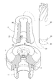
- a tool holder A for mounting a cutting tool on a machining center will be described, for example, with reference to FIG. 1 showing an embodiment of the present invention.
- a shank portion 1 and a chuck portion 2 that can be attached to and detached from a spindle of a machining center are connected to a manipulator gripping portion. 3 are formed integrally.
- the cutting tool 30 has been grasped accurately and firmly by increasing the rotation speed of the spindle, and the rigidity and the performance of rotation balance and the like have been demanded and meet the demand. Attention has been focused on mounting the cutting tool 30 to the chuck portion 2 by shrink fitting (see Patent Documents 1 to 4).
- a conventional machining center having three axes up / down, left / right, and front / rear axis movement
- a five-axis control machining center in which a rotation axis (A axis, B axis) is added to the three axes.
- the gripping force (gripping torque) of the cutting tool holder becomes a problem.
- the gripping force is a force that can withstand the cutting load that the cutting tool 30 receives at the time of cutting, and the higher the gripping force, the more advantageous the improvement in efficiency. That is, the cutting ability increases as the gripping force (griping torque) of the tool holder increases, and the cutting ability decreases as the tool holder decreases.
- the tool holder has a high rigidity (such as a large gripping part outer diameter and a short effective length), and a cutting tool has a high rigidity (such as a short protruding amount and cemented carbide). It is a premise.
- the gripping force is important because the cutting depth can be increased, the feeding amount can be increased, that is, the machining efficiency is increased, and the productivity and cost are greatly affected.
- titanium processing has high mechanical strength of titanium, low thermal conductivity (heat dissipation), good affinity with other metals, and easily reacts with oxygen and nitrogen. Therefore, it is classified as difficult-to-cut material processing.
- the shrink-fit type is capable of high-speed rotation of the main shaft, firmly grasping the cutting tool 30 with high accuracy and high rigidity, and is excellent in performance such as rotation balance.
- Thin and tapered shrink-fit holders are mainly used mainly for deep carving. The main reason is that the interference between the workpiece and the holder is small and the cutting tool can be set relatively short, so that the rigidity is high and it contributes to the improvement of machining accuracy and tool life (see Patent Document 1).
- molds that are partially effective in the fields of high-efficiency machining of aluminum typified by aircraft and difficult-to-cut materials such as titanium It has not reached a satisfactory level like processing.
- JP 2009-45716 A Special table 2009-533234 gazette JP 2001-150221 A Japanese Patent No. 3932216 Japanese Patent Laid-Open No. 05-26264 JP 05-126170 A
- the gripping force of the cutting tool by the holder is about ten times the cutting torque and nearly 30 times the pulling component force, and the cutting tool moves in the axial direction and circumferential direction ( The movement in the rotation direction is mainly due to the bending moment applied to the fulcrum of the cutting tool. For this reason, in order to increase the gripping force of the holder, it is important to prevent the cutting tool from being pulled out and rotated.
- a ball is formed in the outer circumferential surface of the insertion shaft portion of the cutting tool in the circumferential direction, and the groove is projected from the outer circumferential surface of the holder to the inner surface of the cutting tool holding hole.
- a projection or a groove into which the projection is fitted is formed at the insertion end of the cutting tool and the holding hole inner end of the holder, and the cutting tool is prevented from rotating with respect to the holder by the fitting.
- the former retaining / rotation preventing means has a groove whose width is substantially the same as the ball diameter, when inserting a cutting tool into the holder holding hole and fitting the ball into the groove, the ball is inserted into the groove opening.
- the groove extends and bends in the axial direction, the ball does not move smoothly in the groove.
- the positioning of the cutting tool with respect to the holder is performed by contact between the tool insertion end and the holder holding hole inner end (see, for example, Patent Document 2 and FIG. 12), the ball is positioned in the middle of the groove. Can be moved, the above-mentioned retaining / rotating effect is not sufficient.
- the first problem is to prevent the cutting tool from coming off the holder with the other structure, and then the second problem is to perform the same rotation prevention.
- a third problem is to make it possible to easily construct the structure.
- a flat surface cut by a plane in the cutting tool axial direction is formed on the outer peripheral surface of the insertion portion of the cutting tool, and the protrusion on the inner surface of the holder holding hole is After passing through the space between the cut flat surface and the inner peripheral surface of the holding hole and moving it on the flat surface in the axial direction, it fits into the groove in the circumferential direction of the cutting tool continuous with the flat surface. is there.
- the holding hole of the holder is cylindrical and the insertion part of the cutting tool is cylindrical, when a cutting tool is inserted into the holding hole, a space having a substantially crescent shape in cross section is formed between the flat surface and the inner peripheral surface of the holding hole. Since the opening is wide and the opening is wide, if a protrusion hits any of the opening edges, it can be easily recognized that the protrusion is located in the opening. For this reason, the protrusion can be easily introduced into the space with a slight rotation of the tool. After that, the protrusion reaches the groove, and when the cutting tool rotates around the axis with respect to the chuck portion, the groove It shifts to the length direction of and is locked to the groove side edge. The locking prevents the cutting tool from coming off the chuck portion.
- a shank portion that can be attached to and detached from a machine tool and a chuck portion that holds the cutting tool by a shrink-fit method are provided, and the cutting tool is inserted into a cylindrical holding hole of the shank portion.
- a shrink-fit type tool in which a flat surface cut by a plane in the axial direction of the cutting tool is formed on the outer peripheral surface of the cutting tool in the required length from the distal end of the insertion side, and a continuous groove in the circumferential direction of the cutting tool is formed on the flat surface
- the retaining protrusion has a space between the flat surface and the inner peripheral surface of the retaining hole.
- the required length of the flat surface is such that the protrusion fits into the groove before the tool insertion end reaches the holding hole inner end, or the tool insertion end reaches the holding hole inner end and at the same time the protrusion enters the groove.
- the tool is positioned in the axial direction with respect to the chuck portion by fitting the protrusion into the groove, and in the latter case, the tool insertion end is in contact with the inner end of the holding hole and the same positioning is performed.
- the protrusion when the groove is not in the entire circumference of the cutting tool in the circumferential direction and is part of the circumferential direction (up to the middle of the circumferential direction), the protrusion is fitted into the groove to reach the end in the length direction of the groove, If that end is the end of the holder in the anti-cutting rotation direction, the cutting tool is prevented from rotating by the engagement between the projection and the groove end. Furthermore, when the groove is gradually made shallower toward the groove end, the protrusion gradually bites into the groove inner surface, and the biting causes a tightening action on the cutting tool, which effectively prevents the cutting tool from rattling and the cutting tool. The rotation is stopped. If the anti-rotation action is not performed, the projection does not need to be locked to the groove end.
- the cross section perpendicular to the length direction of the retaining protrusion and the groove may be a semicircular shape, a triangular shape, or the like, but preferably has the same shape in consideration of fitting tolerances. If they have the same shape, they will fit perfectly and play will not easily occur.
- the cutting tool holding hole has at least up to the position where the distal end of the cutting tool is inserted, and the cutting tool insertion end normally fits in the chuck portion, but sometimes reaches the shank portion, In such a case, the hole in the shank part is also included.
- a shrink-fit tool holder including a shank portion that can be attached to and detached from a machine tool and a chuck portion that holds the cutting tool by a shrink-fit method.
- a stopper that engages with the groove of the cutting tool is screwed to the end surface of the holding hole of the cutting tool, and the cutting tool is prevented from being pulled out of the chuck by the stopper.
- a cutting screw insertion end of the holding tool is provided with a female screw or a male screw with which the male screw or the female screw at the insertion end of the cutting tool is screwed. It is possible to employ a configuration that prevents the rotation of the tool.
- the means for screwing can also exhibit a rotation stopping function of the cutting tool if the screwing direction is the anti-cutting rotation direction.
- the present invention forms a flat surface cut in a plane in the tool axial direction on the outer peripheral surface of the insertion portion of the cutting tool instead of the bending groove, and holds the holder holding hole.
- the protrusion on the inner surface is positioned in the space between the cut flat surface and the inner peripheral surface of the holding hole.
- the holder holding hole has a cylindrical shape and the cutting tool insertion portion has a columnar shape. Therefore, a substantially crescent-shaped space is formed between the flat surface and the holding hole inner peripheral surface.
- the cutting tool If the cutting tool is rotated with respect to the holder with the protrusion inside, the protrusion will bite between the inner peripheral surface of the holding hole on the end side of the crescent-shaped space and the flat surface of the tool, Effectively prevent rotation. At this time, the biting-in exerts not only the cutting tool's retaining action but also the cutting tool's tightening action, which effectively prevents rattling of the cutting tool. If the orthogonal cross section has a triangular shape projecting toward the axis, when the cutting tool is rotated around the axis with respect to the chuck portion, the cross section between the flat surface and the inner peripheral surface of the holding hole is almost crescent.
- the anti-rotation protrusion bites into the edge of the space, it has a high anti-rotation effect.
- the triangular end portion has the same shape as the crescent-shaped end portion of the space (see FIG. 4 of this application), the bite is more sure.
- this invention has a shank part which can be attached or detached to a machine tool, and a chuck part which holds a cutting tool by a shrink fit type, and the cutting tool has a columnar shape to a cylindrical holding hole of the shank part.
- a shrink-fitting type tool holder in which a flat surface cut in a plane in the cutting tool axial direction is formed on the outer peripheral surface of the insertion portion to have a required length from the distal end of the insertion side, and a rotation-preventing protrusion on the inner surface of the cutting tool holding hole of the chuck portion
- the rotation-preventing protrusion enters the space between the flat surface and the inner peripheral surface of the holding hole.
- the rotation stop protrusion moves around the cutting tool axis in the space and bites into the end of the space, and the cutting tool rotates against the chuck portion by the biting. Configuration can be adopted it was.
- a shrink-fit tool holder including a shank portion that can be attached to and detached from a machine tool and a chuck portion that holds the cutting tool by a shrink-fit method.
- the roller of the one-way clutch comes into contact with the outer peripheral surface of the cutting tool, and the one-way clutch A configuration that allows anti-cutting rotation of the cutting tool can be employed.
- a retaining effect can be obtained by biting the roller of the one-way clutch.
- the structure which achieves this problem 2 can also be adopted in the structure which achieves the above-mentioned problem 1, for example, a structure in which a protrusion for retaining, a one-way clutch, or a stopper is provided, and a cutting tool is screwed into the chuck portion.
- a rotation-preventing protrusion is further provided on the inner surface of the cutting tool holding hole of the chuck portion, and when the retaining protrusion reaches the groove, the rotation-preventing protrusion is in a flat surface, By rotating the cutting tool around its axis with respect to the chuck portion, the rotation stop protrusion bites into the space end between the flat surface and the inner surface of the cutting tool holding hole, and the biting of the cutting tool against the chuck portion by the bite. It can be set as the structure which prevented rotation.
- a conventional side lock can also be adopted in the configuration for achieving the second problem.
- a shank portion that can be attached to and detached from a machine tool, and a cutting tool are provided.
- the cutting tool is provided with a chuck portion that is held by a shrink-fit type, and the cutting tool has a flat surface cut in a plane in the cutting tool axial direction on the outer peripheral surface of the cylindrical insertion portion into the cylindrical holding hole of the chuck portion.
- a rotation stopping projection is provided on the inner surface of the cutting tool holding hole of the chuck portion, and a side pin extending from the outer peripheral surface of the chuck portion to the holding hole is provided. Is inserted into the holding hole so that the anti-rotation projection reaches the flat surface, and then the cutting tool is rotated about its axis with respect to the chuck part. The cutting bites between the flat surface at the end of the space and the inner surface of the cutting tool holding hole, and the biting prevents the cutting tool from rotating relative to the chuck part. In this state, the side pin is screwed into the recess on the outer peripheral surface of the cutting tool. A configuration in which the cutting tool is prevented from being pulled out from the chuck portion by abutting can be employed.
- the rotation-preventing protrusion, the retaining protrusion, the retaining protrusion, and the one-way clutch may be located either before or after the cutting tool axial direction.
- the flat surface is formed to the rear side from the groove or the one-way clutch.
- Each of the protrusions may employ various shapes such as a triangular shape, a semicircular shape, etc., and various forming means, for example, cutting and welding to the inner peripheral surface or inner end surface of the holding hole.
- the pin is inserted into the space from the outer peripheral surface of the chuck portion, and the rotation of the cutting tool with respect to the chuck portion is prevented by contact between the pin and the flat surface You can also. At this time, it becomes easy to insert the pin into the space by making the flat surface and the pin axis direction the same direction (see FIGS. 11 to 17).
- the present invention divides the shank part and the chuck part into separate bodies, and joins the divided parts.
- Various means such as friction welding, TIG welding, and electron beam welding can be used for the joining.
- electron beam welding has the advantage that strong joining and mass productivity are possible, and the shank portion and the chuck.
- the joining accuracy of the part is high, and the chuck part can be joined with very little eccentricity and inclination with respect to the shank part axis. Since each of the protrusions is formed at a deep position inward of the holding hole, when the shank part and the chuck part are not separated, the protrusion is processed (formed) by an opening continuous with the holding hole of the shank part.
- the cutting tool is inserted from the holding hole opening of the chuck portion, and the operation is complicated and a problem is likely to occur in terms of accuracy.
- the shank part and the chuck part are divided, the projection can be processed from the opening of the divided surface, and the distance from the opening to the processing position is shortened, so the work becomes easy. It is easy to ensure accuracy.
- the grooves and protrusions of the shank part and the chuck part in this invention need to be performed after finishing and heat treatment.
- highly accurate joining by the above-mentioned electron beam welding or the like is preferable.
- the protrusion can be formed from the holding hole opening of the dividing surface. Therefore, it is preferable that the dividing surface is close to the formation position of the protrusion. Further, in the case of providing two retaining protrusions and a rotation preventing protrusion that fit into the circumferential groove, if the protrusion is divided between the two protrusions, the protrusions are separately formed on the shank portion and the chuck portion; Therefore, its formation becomes easy. Usually, when cutting the holding hole of the chuck portion, the protrusion forms the holding hole leaving the protruding portion, and then cuts the annular protrusion to the required size (length).
- the one-way clutch can be loaded more easily from the divided surface than from the cutting tool insertion end surface of the holding hole.
- the shrink-fit type is excellent in the performance of rotation balance, and in the present invention, members such as the above-described protrusions, flat surfaces, grooves, one-way clutches, stoppers, pins, etc. that have not been conventionally used are cut. It is preferable to have the same size and weight at equal positions around the tool axis so as not to cause a decrease in the rotational balance performance.
- the cutting tool is prevented from coming off or rotating against the chuck portion with a configuration which has not been heretofore obtained, it is possible to obtain effects such as good manufacturability of the means. it can
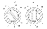
- FIGS. 2A and 2B are diagrams illustrating a cutting operation along the line aa in FIG. 1 according to the embodiment, where FIG. 1A is an initial stage of insertion of the cutting tool, and FIG. FIG. 2B is a sectional view taken along the line bb of FIG. 1 of the embodiment, where (a) is an initial stage of insertion of the cutting tool, and (b) is after loading with the cutting tool rotated.
- FIG. 1A is an initial stage of insertion of the cutting tool
- FIG. 2B is a sectional view taken along the line bb of FIG. 1 of the embodiment, where (a) is an initial stage of insertion of the cutting tool, and (b) is after loading with the cutting tool rotated.
- FIG. 4 shows another embodiment, (a) is a partially cut front view, (b) is a sectional view taken along line XX of (a). Partially cut front view of another embodiment Fig. 4 shows another embodiment, (a) is a partially cut front view, (b) is a right side view thereof, (c) is a front view of the cutting tool, and (d) is a main part in which the cutting tool is loaded in the tool holder.
- Cross section Other embodiments are shown, in which (a) is a partially cut front view, (b) is a partial front view of a cutting tool, and (c) is a cross-sectional view of a main part in which a cutting tool is loaded into a tool holder.
- (a) is a partially cut front view
- (b) is a partially cut front view of a cutting tool
- (c) is a cross-sectional view of a main part in which a cutting tool is loaded in a tool holder.
- (A) is the cut front view of other embodiment, (b), (c) is the action explanatory drawing.
- Cut front view of another embodiment is a principal part cutting front view of other embodiment
- (b) is a front view of the cutting tool.
- (A) is a partially cut front view of a tool holder according to another embodiment
- (b) is a front view of a main part of the cutting tool
- (c) is a front view of a main part of the tool holder loaded with a cutting tool.
- (A) is a partially cut front view of a tool holder of another embodiment
- (b) is a cut front view of a main part of the cutting tool
- (c) is a cut front view of a main part in which the cutting tool is loaded in the tool holder.
- Cut front view of another embodiment is a partially cut front view of a tool holder of another embodiment
- (b) is a left side view of the cutting tool
- (c) is a front view of the main part of the cutting tool.
- Cut front view of another embodiment Partial plan view of each other example of the retaining groove of the cutting tool
- the other cutting tool with which the tool holder of each embodiment is loaded is shown, (a) is a front view, (b) is a top view, (c) is a left side view of (a), (d) is (b). Left side view It is a cutting action figure by the cutting tool, (a) is the initial stage of insertion of the cutting tool, (b) is after loading the cutting tool is rotated
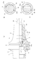
- FIG. 1 to 4 show a tool holder A according to this embodiment, in which a shank portion 1 and an inverted frustoconical chuck portion 2 that can be attached to and detached from a main spindle of a machining center are connected to a manipulator for an automatic tool changer (ATC). It is integrated through a gripping part (V flange part) 3.
- the shank part 1 and the chuck part 2 are divided with the manipulator gripping part 3 as the shank part side.
- the split surface has a cylindrical fitting convex part on the chuck part side and a cylindrical fitting part on the shank part side.
- the shank portion 1 and the chuck portion 2 are joined by electron beam welding.
- the fitting between the chuck part 2 and the shank part 1 can be a concave part on the chuck part 2 side and a convex part on the shank part 1 side.
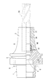
- the holding hole 20 of the cutting tool 30 is formed in a cylindrical shape on the axial center from the tip surface (the right end surface in FIG. 1) of the chuck portion 2 to the manipulator grip portion 3.
- the minimum diameter of the holding hole 20 (the opening diameter of the front end surface) is slightly smaller than the diameter of the insertion portion (held portion) 31 of the cutting tool 30, and the chuck portion 2 is thermally expanded by heating (holding hole).
- the cutting tool 30 is inserted into the holding hole 20 and cooled by expanding the diameter 20), and the cutting tool 30 is firmly supported and fixed to the chuck portion 2 by shrink fitting.
- the chuck part 2 for example, the material described in Patent Document 4 is used.
- Two retaining projections 21 are provided on the inner surface of the holding hole 20 near the dividing surface of the chuck portion 2 symmetrically with respect to the chuck portion axis.
- the protrusion 21 is formed by first forming a semicircular cross-sectional ridge around the circumference of the hole 20 and then cutting a part around the ridge.
- the surface is straight and formed in a semicircular cross section perpendicular to the cutting tool axial direction.
- the number of the protrusions 21 may be three, four, etc. as long as they are equidistant around the axis, but the same number as the flat surface 32 of the cutting tool 30 described later.
- a triangular protrusion for cross-section 22 perpendicular to the cutting tool axial direction has a chuck part (shank part) axis.
- the protrusions 22 are formed in the same manner as the protrusions 21, and the number of the protrusions 22 may be the same number as the flat surface 32, such as three, four, etc., as long as the number of the protrusions 22 is equal around the axis. The reason for providing them at equal intervals is to balance during rotation.
- the center lines in the cutting tool circumferential direction of the protrusions 21 and 22 are deviated by 45 degrees with respect to the tool axis.
- 4 is a female screw for mounting the coolant duct 6 (see FIG. 17)
- 5 is a non-slip pin provided on the holder, and this pin 5 is locked to the end face of the main shaft to prevent the holder from sliding (around) the main shaft. To prevent.
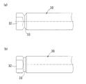
- the cutting tool 30 attached to the tool holder A of this embodiment is an end mill having a large diameter, for example, a diameter of 12 to 32 mm, and a flat surface 32 on the outer peripheral surface of the end portion of the insertion portion 31 into the holding hole 20.
- the flat surface 32 has a shape obtained by cutting the outer peripheral surface of the cutting tool insertion portion 31 in a plane in the tool axis direction.
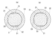
- the holding hole 20 is cylindrical. Since the insertion part 31 of the cutting tool is cylindrical, a space S having a substantially crescent-shaped cross section is formed between the flat surface 32 and the inner peripheral surface of the holding hole.
- a semicircular groove 33 having a cross-section in the same concentric direction of the cutting tool 30 is continuously formed at the rear end (the front end side of the chuck portion 2) of the flat surface 32.
- the protrusion 22 enters one end of the crescent-shaped space S, and the protruding amount of the cutting tool 30 from the tool holder A is determined by the end surface of the cutting tool insertion portion coming into contact with the back wall of the holding hole 20.
- the protrusion 21 is located in the groove 33 from the flat surface 32, and the protrusion 21 and the groove 33 at the position are fitted and allow movement in the groove length direction in the groove 33. Is not allowed to move in the width direction (the axial direction of the cutting tool 30) (see FIG. 1).
- the flat surface 32 serves as a reference surface when the cutting tool 30 is locked (attached) to the tool holder A, and also serves as a reference surface when the cutting tool is ejected (removed). Is provided with a mark such as a mark indicating the position of the flat surface 32 (corresponding to the protrusion 21) with respect to the holding hole 20 so that the protrusions 21 and 22 can be smoothly introduced into and extracted from the space S. Is preferred.
- the rotation preventing projection 22 has the same shape as the other end of the space S having a triangular cross section orthogonal to the cutting tool axial direction (see FIG. 4B), and is located in the other end of the space S. Since it bites in a wedge shape, the rotation stopper is effectively exhibited.
- the cutting tool 30 is loaded into the tool holder A in a state where the tool holder A (a part of the chuck portion 2 and the manipulator gripping portion 3) is heated and thermally expanded to expand the holding hole 20 in the same manner as in the past. Done. Therefore, when the tool holder A is cooled, the cutting tool 30 is shrink-fitted to the tool holder A in a state where the protrusion 21 is locked to the edge of the groove 33 and the protrusion 22 is bitten into the end of the space S. In addition to being firmly loaded, the cutting tool 30 is securely prevented from coming off and rotating against the chuck portion 2. That is, the gripping force is strong. The cutting tool 30 is detached from the tool holder A by heating and expanding the tool holder A to expand the diameter of the holding hole 20, and then rotating and extracting the cutting tool 30 opposite to the above operation.
- both the protrusions 21 and 22 need to be introduced into the space S by the insertion of the cutting tool 30 into the holding hole 20, the deviation angle of the protrusions 21 and 22 in the circumferential direction of the cutting tool is large in the space S. In consideration of the thickness (the depth in the radial direction) and the like, it is determined appropriately so that the introduction is smoothly performed. At this time, if the protrusion 22 enters the space S, the cutting tool A rotates to bite into the end of the space S and exerts an anti-rotation effect.
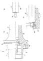
- FIG. 6 shows another embodiment, and this tool holder A is provided with pins 25 symmetrically about its axis on the inner surface of the holding hole 20 as shown in FIG. is there.
- the pin 25 has a cylindrical shape, and the pin 25 is inserted into a hole 25a penetrating the chuck portion 2, and screws 25b are screwed into both ends of the hole 25a to prevent the pin 25 from coming off.
- the cutting tool 30 is inserted into the holding hole 20 of the tool holder A (chuck portion 2) with the flat surface 32 corresponding to the pin 25, the pin 25 slides on the flat surface 32 and passes through the space S to form the groove 33.
- the cutting tool 30 is rotated, it moves from the flat surface 32 into the groove 33 and fits. By this fitting, the function of preventing the cutting tool 30 from coming off from the chuck portion 2 is exhibited.
- the groove 33 is not the entire circumference in the circumferential direction but a part thereof is missing, and the pin 25 is brought into contact with the groove end of the lacking part, the contact of the cutting tool 30 with respect to the chuck part 2 is caused by the contact.
- the retaining and anti-rotation functions are exhibited. Even if the groove 33 is not formed, the pin 25 is positioned on the flat surface 32, so that the function of preventing the rotation of the cutting tool 30 relative to the chuck portion 2 is exhibited, and the pin 25 bites into the space S.
- the retaining function is also demonstrated.
- the pin 25 since the pin 25 is inserted from the outer peripheral surface of the chuck portion 2, the insertion hole 25a is easily formed, and the chuck portion 2 and the shank portion 1 do not need to be divided. That is, they can be the same member. Further, the pin 25 may be a polygonal column shape such as a quadrangular columnar shape because it may slide on the flat surface 32 without being a columnar shape.
- the rotation stopping function of the cutting tool 30 with respect to the chuck portion 2 by the protrusion 22 biting between the holding hole inner peripheral surface and the flat surface 32 is not limited.
- FIG. 7 shows still another embodiment.
- a one-way clutch (one-way clutch) 40 is provided on the inner peripheral surface of the holding hole 20 of the chuck portion 2, and the chuck 40 in the cutting rotation direction is provided by the clutch 40.
- the rotation of the cutting tool 30 relative to the part 2 is prevented. That is, when the cutting tool 30 is inserted into the holding hole 20, the roller 41 of the one-way clutch 40 comes into contact with the outer peripheral surface of the insertion part 31 of the cutting tool, and the one-way clutch 40 is connected to the tool holder A (chuck part 2). However, when rotating in the cutting direction, the roller 41 bites into the gap between the cutting tool 30 and prevents the cutting tool 30 from rotating relative to the chuck portion 2.
- a conventionally known one shown in Patent Documents 5 and 6 is appropriately selected.
- the annular recess is formed in the inner surface of the holding hole 20 and the one-way clutch 40 is fitted into the recess, the recess is easy to form, and therefore the chuck portion 2 and the shank portion 1 do not need to be divided. . That is, they can be the same member.
- the above-described flat surface 32 is formed on the cutting tool 30, and an axially long protrusion such as a roller 41 provided by being embedded in the inner surface of the holding hole 20 in the space S formed by the flat surface 32. If the cutting tool A can be introduced, the protrusions bite into the end of the space S by the rotation of the cutting tool A, thereby exhibiting the anti-rotation action.
- FIG. 8 shows still another embodiment.
- This tool holder A is not provided with the projections 21 and 22 and the flat surface 32 as in the above embodiments, and the cutting tool is inserted into the holding hole 20 of the chuck portion 2.
- a stopper 45 engaged with the groove 34 of the cutting tool 30 is screwed to the side end face.
- This stopper 45 is divided into two parts, but more than that, for example, three parts, four parts, etc., are arbitrary, but the divided pieces can be the same size (weight) and balance during rotation can be taken. preferable. At this time, if a balance is achieved, for example, in the case of four divisions, a part can be omitted, for example, by providing the other two members with two members omitted at equal intervals.
- the stopper 45 is screwed with a screw 45a so that the stopper 45 becomes a groove (step difference) in the cutting tool 30. ) 34 and the cutting tool 30 is prevented from being pulled out from the chuck portion 2.
- the groove 34 is a part of the periphery, for example, the flat surface 32 or the like, the stopper 45 can be brought into contact with the end of the groove so that the rotation stopping function can be exhibited.
- the inner hole of the stopper 45 (the insertion hole of the cutting tool 30) is also adapted to the groove shape (for example, a shape lacking a part of a circular shape (arc-shaped portion)).
- FIGS. 9 and 10 show still another embodiment.
- the tool holder A is not provided with the protrusions 21 and 22 and the flat surface 32 as in the above embodiments, and the chuck portion holding hole 20 is not provided.
- a female screw 46 or a male screw 47 with which the male screw 35 or the female screw 36 at the insertion end of the cutting tool 30 is fitted is provided at the cutting tool insertion end.
- the female screw 46 or the male screw 47 is constituted by coolant ducts 7 and 7 ′ formed by extending the tip end portion of the coolant duct 6 into the holding hole 20. In this embodiment, as shown in FIGS.
- the pin 22a can be used instead of the protrusion 22 to exhibit a rotation stopping function. That is, in the embodiment of FIG. 1, as shown in FIG. 11, the pin 22a at the same position as the protrusion 22 is provided on the dividing surface on the shank portion 1 side in a protruding state by appropriate means such as screwing and fitting. Similarly to the above, the cutting tool 30 is inserted into the holding hole 20 of the chuck portion 2 (tool holder A) so that the flat surface 32 corresponds to the protrusion 21 and the pin 22a, and the end surface of the cutting tool insertion portion is the holding hole.
- the embodiment shown in FIG. 6 is shown in FIG. 13, and in the embodiment shown in FIG. 9, as shown in FIG. Then, as shown in FIG. 15, by providing the pins 22a on the dividing surface on the shank portion 1 side in a protruding state, the anti-rotation function can be similarly exhibited.
- the cutting tool 30 is shown in FIG. 3 in which a flat surface 32 and a groove 33 are formed, and in the embodiment of FIG. 13, the cutting tool 30 is a flat surface shown in FIG. 14 and 15, the cutting tool 30 is assumed to have a flat surface 32 shown in FIG. 14B or 15B.
- FIG. 3 in which a flat surface 32 and a groove 33 are formed
- the cutting tool 30 is a flat surface shown in FIG. 14 and 15, the cutting tool 30 is assumed to have a flat surface 32 shown in FIG. 14B or 15B.
- the cutting tool 30 is inserted and rotated into the holding hole 20 of the chuck portion 2 so that the pin 22a is bitten between the inner surface of the holding hole 20 and the flat surface 32, and then shrink-fitted.
- the cutting tool 30 may be fixed to the chuck portion 2 and then the stopper 45 may be attached, or the stopper 45 may be attached after the biting, and then the cutting tool 30 may be fixed to the chuck portion 2 by shrink fitting.
- the projection 21 is provided in the dividing portion on the shank portion 1 side, and the cutting tool 30 is shown in FIG. 3 in which a flat surface 32 and a groove 33 are formed. If so, the retaining function can be exhibited in the same manner as described above.
- the configuration of the pin 25 of FIG. the retaining function of the cutting tool 30 can be performed by a pin 21a screwed from the outer peripheral surface of the chuck portion 2 as in the conventional side lock function.
- the cutting tool 30 is formed with a flat surface 32a with which the tip of the pin 21a abuts.
- the anti-rotation function can be the illustrated pin 22a or the protrusions 22 and 22a.
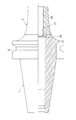
- shank portion 1 is not limited to the HSK shape of each of the above-described embodiments, but may have various conventionally known shapes such as the BT shape shown in FIG.
- the anti-rotation protrusion 22 can also be formed on the inner surface of the holding hole 20 on the chuck portion 2 side as shown in FIG.
- the cross-sectional shape of the groove 33 is not limited to the circular arc shape, and is arbitrary such as a triangular cross section shown in FIG. 19A and a trapezoidal shape shown in FIG.
- the protrusion 21 and the groove 33 fit perfectly and movement in the groove length direction in the groove 33 is allowed
- the movement in the width direction of the groove 33 is arbitrary as long as it exhibits an operation that is not allowed.
- the groove 33 can be halfway in the counter-cutting direction instead of the entire circumference in the circumferential direction. Preventive action is performed. For this reason, the rotation stop protrusion 22 becomes unnecessary.
- the groove 33 has a circular cross section, a triangular cross section, etc., and gradually becomes shallower and narrower toward the groove end, as shown in FIG. 21 (a) to FIG.
- the projections 21 bite into the inner surface of the groove 33 in a wedge shape, causing a tightening action on the cutting tool 30 and effectively preventing play of the cutting tool 30.
- the depth and width of the groove 33 are the same up to the end of the groove, the retaining and anti-rotation action can be exhibited.
- the positions of the rotation stopping projections 22 and 22a may be appropriately changed to the cutting direction side. For example, cutting may be performed in a state in which the protrusions 22 in FIG. 4 bite between the inner surface of the holding hole 20 and the flat surface 32.
- the rotation prevention direction is the cutting direction.
- the tool holder of the present invention can be used not only in 5-axis control but also in multi-axis control over 5-axis control such as 2-axis control, 3-axis control, or 6-axis control.
- 5-axis control such as 2-axis control, 3-axis control, or 6-axis control.
Abstract
Description
この工具ホルダAにおいて、近年、主軸の高速回転化により、切削工具30を精度良く強固に把握し、かつ剛性を有する上に、回転バランス等の性能の高度化が望まれ、その要求をみたすものとして、上記チャック部2に切削工具30を焼嵌め式でもって装着するものが注目されている(特許文献1~4参照)。 A tool holder A for mounting a cutting tool on a machining center will be described, for example, with reference to FIG. 1 showing an embodiment of the present invention. A
In this tool holder A, in recent years, the
これらの難削材を高能率に加工する工作機械(マシニングセンタ)は、アルミ加工の場合、主軸回転数が33000rpm以上に及んだり、主軸電動機出力が80kW(100馬力)以上に及んだり、チタン加工の場合、主軸トルクが1500Nm以上に及び、それらを担うものが製品化されている。
また、加工方法においては、従来の3軸(上下、左右、前後の軸移動)を持つマシニングセンタでは加工効率が悪く、3軸に回転軸(A軸、B軸)を付加した5軸制御マシニングセンタを活用するケースが増えている。 On the other hand, due to the advancement of technology in recent years, there are an increasing number of difficult-to-cut material processed parts such as aluminum alloy parts and titanium alloys in the aerospace and motor related fields. For example, aluminum structural parts such as aircraft frames, wing ribs and bulkheads, titanium frame parts such as frame components, edge frames, and motor blades and impellers.
Machine tools (machining centers) that process these difficult-to-cut materials with high efficiency have a spindle speed of 33,000 rpm or more, a spindle motor output of 80 kW (100 horsepower) or more in the case of aluminum machining. In the case of machining, the main shaft torque reaches 1500 Nm or more, and those bearing these are commercialized.
In the machining method, a conventional machining center having three axes (up / down, left / right, and front / rear axis movement) has poor machining efficiency, and a five-axis control machining center in which a rotation axis (A axis, B axis) is added to the three axes. Increasing use cases.
その把持力は、切削工具30が切削時に受ける切削負荷に耐え得る力であって、高いほど高能率化に有利である。つまり、工具ホルダの把持力(把持トルク)が大きいほど切削能力が高く、小さいほど切削能力は低下する。このとき、高能率化のためには、工具ホルダの剛性(把持部外径が太く、有効長が短いなど)が高く、切削工具の剛性(突き出し量が短い、超硬製など)も高い設定であることが前提である。このように、把持力が重要とされるのは、切込み量が大きく取れる、送り量を大きくできる、つまり加工能率が上がり、生産性とコストに大きな影響を及ぼすからである。 In the processing of the above-mentioned difficult-to-cut material, particularly in the high-speed processing of the difficult-to-cut material by a 5-axis control machining center, the gripping force (gripping torque) of the cutting tool holder becomes a problem.
The gripping force is a force that can withstand the cutting load that the
また、チタン加工は、チタンの機械的強度が高く、熱伝導率(放熱性)が低いうえに、他の金属と親和性が良く、酸素や窒素と反応しやすい。そのため、難削材加工に分類されている。さらに、チタン特有の鋸刃状の切りくずが生成されるが、これは切削力が変動するために起きる現象で、この変動に伴い大きな「びびり」が生じる。それにより、切削工具は短時間で消耗し、磨耗した切削工具は切削トルクを増大させ、切削工具のスリップや抜けを引き起こすこととなる。
さらに、航空機関連の部品加工は、巨大な被削材より削り出しで部品を製作する場合が多いため、その被削材は高価であり、切削工具の抜けによる削り過ぎは修正が不可能であり莫大な損害が発生してしまう。
そのため、安全率を高く設定し、加工条件を落とすなど、本来期待される高能率加工が十分に発揮できないのが現状である。 Here, in aluminum processing, high-efficiency processing can be expected as the cutting speed is increased. Moreover, since the aluminum alloy has a lower material strength than steel, the cutting depth can be increased. The machining conditions are set so as to increase the amount of cutting removal as much as possible, but large chatter (vibration) is likely to occur during machining. When the tool holder or the cutting tool is subjected to large chatter (vibration), even if the gripping force is considered to be suitable, the tool holder and the cutting tool may easily slip and the cutting tool may come off.
Titanium processing has high mechanical strength of titanium, low thermal conductivity (heat dissipation), good affinity with other metals, and easily reacts with oxygen and nitrogen. Therefore, it is classified as difficult-to-cut material processing. In addition, sawtooth-shaped chips peculiar to titanium are generated, and this is a phenomenon that occurs because the cutting force fluctuates, and a large “chatter” occurs with this fluctuation. As a result, the cutting tool is consumed in a short time, and the worn cutting tool increases the cutting torque, causing the cutting tool to slip and come off.
In addition, aircraft-related parts processing often produces parts by cutting out from a huge work material, so the work material is expensive, and it is impossible to correct overcutting due to missing cutting tools. Enormous damage will occur.
For this reason, the high-efficiency machining originally expected, such as setting a high safety factor and reducing machining conditions, cannot be fully achieved.
しかし、上記テーパ形状の焼嵌め式ホルダであっても、航空機関連に代表されるアルミの高能率加工やチタンなどの難削材加工の分野においては、一部で効果を上げているものの金型加工のように十分満足できるものに至っていない。 As described above, the shrink-fit type is capable of high-speed rotation of the main shaft, firmly grasping the
However, even with the above-mentioned taper-shaped shrink-fit holders, molds that are partially effective in the fields of high-efficiency machining of aluminum typified by aircraft and difficult-to-cut materials such as titanium It has not reached a satisfactory level like processing.
ここで、ホルダによる切削工具の把持力は、切削トルクに対して十数倍、引き抜き分力に対して30倍近くあり、作業中に、ホルダに対して切削工具がその軸方向や周方向(回転方向)に動くのは、主に、切削工具の支点にかかる曲げモーメントによるものである。このため、ホルダの把持力を高めるには、その切削工具の引き抜きと回転を阻止することが重要である。
その切削工具のホルダからの抜け出し・回転防止手段として、切削工具の挿入軸部の外周面にその周方向の溝を形成し、その溝にホルダ外周面から切削工具保持孔内面に突出させたボールを嵌め、その嵌合によって、ホルダに対する切削工具の抜け止め及び回転止めを行なうものがある(特許文献2 要約、図1~図22参照)。
また、他の手段として、切削工具の挿入端とホルダの保持孔内端に突起又はその突起が嵌合する溝を形成し、その嵌合によって、ホルダに対する切削工具の回転止めを行なうものがある(特許文献3 図8参照)。 In high-efficiency machining of aluminum alloys and titanium such as the above-mentioned aerospace, prime movers, etc., it is necessary to take measures to prevent the tool holder from coming off while making the overall length of the tool holder as short as possible, setting the protruding amount of the cutting tool to a minimum.
Here, the gripping force of the cutting tool by the holder is about ten times the cutting torque and nearly 30 times the pulling component force, and the cutting tool moves in the axial direction and circumferential direction ( The movement in the rotation direction is mainly due to the bending moment applied to the fulcrum of the cutting tool. For this reason, in order to increase the gripping force of the holder, it is important to prevent the cutting tool from being pulled out and rotated.
As a means for preventing the cutter from coming out of the holder and preventing rotation, a ball is formed in the outer circumferential surface of the insertion shaft portion of the cutting tool in the circumferential direction, and the groove is projected from the outer circumferential surface of the holder to the inner surface of the cutting tool holding hole. Are fitted to prevent the cutting tool from coming off and rotating against the holder (see the abstract of
Further, as another means, there is a method in which a projection or a groove into which the projection is fitted is formed at the insertion end of the cutting tool and the holding hole inner end of the holder, and the cutting tool is prevented from rotating with respect to the holder by the fitting. (Refer
後者の回転止め手段は、切削工具の挿入端の突起とホルダの保持孔内端の溝との嵌合によるため、切削工具をホルダ保持孔に挿入して溝に突起を嵌合する際、溝に突起がスムースに入りにくい問題がある。また、抜け止め作用は発揮し得ない。 However, since the former retaining / rotation preventing means has a groove whose width is substantially the same as the ball diameter, when inserting a cutting tool into the holder holding hole and fitting the ball into the groove, the ball is inserted into the groove opening. However, when the cutting tool is rotated with respect to the holder, since the groove extends and bends in the axial direction, the ball does not move smoothly in the groove. Further, since the positioning of the cutting tool with respect to the holder is performed by contact between the tool insertion end and the holder holding hole inner end (see, for example,
The latter anti-rotation means is due to the fitting of the projection at the insertion end of the cutting tool and the groove at the inner end of the holder holding hole, so when inserting the cutting tool into the holder holding hole and fitting the projection into the groove, the groove There is a problem that the protrusion is difficult to enter smoothly. Moreover, the retaining action cannot be exhibited.
ホルダの保持孔は円筒状、切削工具の挿入部は円柱状であるから、切削工具を前記保持孔に挿入すると、上記フラット面と保持孔内周面の間には断面ほぼ三日月状のスペースが形成され、そのスペースは、その開口が広いため、その開口縁の何れかに突起が当たれば、その突起が開口に位置したことを容易に認識できる。このため、工具を少し回転させるだけで、そのスペースに突起を容易に導き入れることができ、その後、突起は、前記溝内に至ってチャック部に対し切削工具がその軸心周りに回転すると、溝の長さ方向に移行してその溝側縁に係止する。その係止によってチャック部に対する切削工具の抜け止めが行なわれる。 In order to achieve the above-mentioned
Since the holding hole of the holder is cylindrical and the insertion part of the cutting tool is cylindrical, when a cutting tool is inserted into the holding hole, a space having a substantially crescent shape in cross section is formed between the flat surface and the inner peripheral surface of the holding hole. Since the opening is wide and the opening is wide, if a protrusion hits any of the opening edges, it can be easily recognized that the protrusion is located in the opening. For this reason, the protrusion can be easily introduced into the space with a slight rotation of the tool. After that, the protrusion reaches the groove, and when the cutting tool rotates around the axis with respect to the chuck portion, the groove It shifts to the length direction of and is locked to the groove side edge. The locking prevents the cutting tool from coming off the chuck portion.
また、上記溝が切削工具周方向全周になく、周方向一部の場合(周方向の途中までの場合)、上記突起を上記溝に嵌めてその溝の長さ方向の端に至らし、その至った端がホルダの反切削回転方向の端であると、その突起と溝端の係止によって切削工具の回転止めが行なわれる。さらに、その溝をその溝端に向かって徐々に浅くすると、突起が溝内面に徐々に食込み、その食い込みによって、切削工具に締付け作用が生じて切削工具のガタが有効に防止されるとともに切削工具の回転止めが行なわれる。回転止め作用を行なわないのであれば、突起は、溝端に係止させる必要はない。
上記抜け止め用突起と溝のその長さ方向に直交する断面は、半円状、三角状等が考え得るが、嵌り公差を考慮した同一形状とすることが好ましい。同一形状であると、ピッタリ嵌ってガタが生じにくい。
ここで、切削工具保持孔は、切削工具の挿入側先端が至る位置までを少なくとも有するものであって、その切削工具挿入端は、通常、チャック部内で収まるが、シャンク部内に至る場合もあり、そのような場合は、そのシャンク部内の孔も含むものとする。 In this configuration, the required length of the flat surface is such that the protrusion fits into the groove before the tool insertion end reaches the holding hole inner end, or the tool insertion end reaches the holding hole inner end and at the same time the protrusion enters the groove. Set as appropriate to fit. In the former case, the tool is positioned in the axial direction with respect to the chuck portion by fitting the protrusion into the groove, and in the latter case, the tool insertion end is in contact with the inner end of the holding hole and the same positioning is performed. Become.
In addition, when the groove is not in the entire circumference of the cutting tool in the circumferential direction and is part of the circumferential direction (up to the middle of the circumferential direction), the protrusion is fitted into the groove to reach the end in the length direction of the groove, If that end is the end of the holder in the anti-cutting rotation direction, the cutting tool is prevented from rotating by the engagement between the projection and the groove end. Furthermore, when the groove is gradually made shallower toward the groove end, the protrusion gradually bites into the groove inner surface, and the biting causes a tightening action on the cutting tool, which effectively prevents the cutting tool from rattling and the cutting tool. The rotation is stopped. If the anti-rotation action is not performed, the projection does not need to be locked to the groove end.
The cross section perpendicular to the length direction of the retaining protrusion and the groove may be a semicircular shape, a triangular shape, or the like, but preferably has the same shape in consideration of fitting tolerances. If they have the same shape, they will fit perfectly and play will not easily occur.
Here, the cutting tool holding hole has at least up to the position where the distal end of the cutting tool is inserted, and the cutting tool insertion end normally fits in the chuck portion, but sometimes reaches the shank portion, In such a case, the hole in the shank part is also included.
このねじ合いによる手段は、ねじ合い方向を反切削回転方向とすれば、切削工具の回転止め機能も発揮し得るものとすることができる。 In another aspect of the present invention for achieving the
The means for screwing can also exhibit a rotation stopping function of the cutting tool if the screwing direction is the anti-cutting rotation direction.
上記のように、ホルダの保持孔は円筒状、切削工具の挿入部は円柱状であるから、上記フラット面と保持孔内周面の間には断面ほぼ三日月状のスペースが形成され、そのスペース内に突起が入った状態で、ホルダに対し切削工具を回転すれば、前記突起はその三日月状スペースの端側の保持孔内周面と工具フラット面の間に食込んで、ホルダに対する工具の回転を有効に防止する。このとき、その食い込みによって、切削工具の抜け止め作用も少なからず発揮されるとともに、切削工具に締付け作用が生じて切削工具のガタツキも有効に防止される
その回転止め用突起は切削工具軸方向に直交する断面がその軸心に向かって突出する三角形状となっておれば、切削工具をチャック部に対して軸心周りに回転すると、上記フラット面と保持孔内周面の間の断面ほぼ三日月状のスペースの端に回転止め用突起は楔状に食込むため、その回転止め効果の高いものとなる。このとき、その三角形状の端部はスペースの三日月形状の端部と同じ形状とすれば(本願図4参照)、その食い込みがより確実となる。 In order to achieve the above-mentioned
As described above, the holder holding hole has a cylindrical shape and the cutting tool insertion portion has a columnar shape. Therefore, a substantially crescent-shaped space is formed between the flat surface and the holding hole inner peripheral surface. If the cutting tool is rotated with respect to the holder with the protrusion inside, the protrusion will bite between the inner peripheral surface of the holding hole on the end side of the crescent-shaped space and the flat surface of the tool, Effectively prevent rotation. At this time, the biting-in exerts not only the cutting tool's retaining action but also the cutting tool's tightening action, which effectively prevents rattling of the cutting tool. If the orthogonal cross section has a triangular shape projecting toward the axis, when the cutting tool is rotated around the axis with respect to the chuck portion, the cross section between the flat surface and the inner peripheral surface of the holding hole is almost crescent. Since the anti-rotation protrusion bites into the edge of the space, it has a high anti-rotation effect. At this time, if the triangular end portion has the same shape as the crescent-shaped end portion of the space (see FIG. 4 of this application), the bite is more sure.
この構成においては、ワンウェイクラッチのコロの食い込みによって抜け止め効果も得ることができる。 As another configuration of the present invention for achieving the above-described
In this configuration, a retaining effect can be obtained by biting the roller of the one-way clutch.
また、上記各突起には上記断面三角形状、半円状等と種々の形状を採用することができるとともに、その形成手段も種々のもの、例えば、保持孔内周面又は内端面に切削、溶接、嵌合等によって突起を直接に形成することは勿論のこと、チャック部外周面からピンを上記スペースに嵌入し、そのピンとフラット面との当接によってチャック部に対する切削工具の回転を防止することもできる。このとき、そのフラット面とピン軸方向を同一方向とすることによってピンをスペースに挿入することが容易となる(図11~図17参照)。 In each of the above-described configurations, the rotation-preventing protrusion, the retaining protrusion, the retaining protrusion, and the one-way clutch may be located either before or after the cutting tool axial direction. However, when the retaining protrusion is on the rear side (on the tool insertion end side of the holding hole), the flat surface is formed to the rear side from the groove or the one-way clutch.
Each of the protrusions may employ various shapes such as a triangular shape, a semicircular shape, etc., and various forming means, for example, cutting and welding to the inner peripheral surface or inner end surface of the holding hole. In addition to forming the protrusion directly by fitting, etc., the pin is inserted into the space from the outer peripheral surface of the chuck portion, and the rotation of the cutting tool with respect to the chuck portion is prevented by contact between the pin and the flat surface You can also. At this time, it becomes easy to insert the pin into the space by making the flat surface and the pin axis direction the same direction (see FIGS. 11 to 17).
上記各突起は、保持孔の内方深い位置に形成するため、シャンク部とチャック部とが分割されていない一体ものの場合、その突起の加工(形成)は、シャンク部の保持孔に連続する開口又はチャック部の保持孔開口から、切削工具を挿入して行なうこととなり、その作業は繁雑であって、精度的にも問題が生じやすい。これに対し、シャンク部とチャック部とを分割すれば、その分割面の開口から、前記突起の加工を行なうことができ、その開口から加工位置までの距離も短くなるため、作業も容易となり、精度も確保し易くなる。
因みに、複数の部材を接合する場合、一般的には、素形材同士、又は前加工後の接合が多いが、この発明におけるシャンク部とチャック部の溝や突起は仕上げ加工及び熱処理後に行なう必要があり、その加工処理後にシャンク部とチャック部とを接合するため、上記電子ビーム溶接等による高精度な接合が好ましい。 In order to achieve the above-mentioned
Since each of the protrusions is formed at a deep position inward of the holding hole, when the shank part and the chuck part are not separated, the protrusion is processed (formed) by an opening continuous with the holding hole of the shank part. Alternatively, the cutting tool is inserted from the holding hole opening of the chuck portion, and the operation is complicated and a problem is likely to occur in terms of accuracy. On the other hand, if the shank part and the chuck part are divided, the projection can be processed from the opening of the divided surface, and the distance from the opening to the processing position is shortened, so the work becomes easy. It is easy to ensure accuracy.
Incidentally, when joining a plurality of members, in general, there are many joining between the shaped members or after the pre-processing, but the grooves and protrusions of the shank part and the chuck part in this invention need to be performed after finishing and heat treatment. In order to join the shank part and the chuck part after the processing, highly accurate joining by the above-mentioned electron beam welding or the like is preferable.
そのシャンク部1とチャック部2はマニュピレータ把持部3をシャンク部側にして分割され、その分割面は、図2に示すように、チャック部側が円筒状嵌合凸部、シャンク部側が円筒状嵌合凹部の形状となっており、前記円筒状嵌合凸部端面と円筒状嵌合凹部内端面の間には空隙が生じている。このシャンク部1とチャック部2の接合は電子ビーム溶接によって行なう。チャック部2とシャンク部1との嵌合は、チャック部2側を凹部、シャンク部1側を凸部とし得る。 1 to 4 show a tool holder A according to this embodiment, in which a
The
一方、シャンク部2(マニュピレータ把持部3)の分割面近くの保持孔20内面にも、同様に、切削工具軸方向に直交する断面三角状回転止め用突起22がチャック部(シャンク部)軸心に対し対称に2個設けられている。この突起22は、突起21と同様にして形成し、その数も軸心周りに等間隔であれば、フラット面32と同一の数の3個、4個等といずれでもよい。このように等間隔に設けるのは、回転時のバランスを取るためである。
この両突起21、22の切削工具周方向の中心線はその工具軸心に対して45度ずれている。図中、4はクーラントダクト6(図17参照)の取付用雌ねじ、5はホルダに設けた滑り止めピンであり、このピン5が主軸端面に係止して主軸に対するホルダの滑り(回り)を防止する。 Two retaining
On the other hand, on the inner surface of the holding
The center lines in the cutting tool circumferential direction of the
このフラット面32は、切削工具挿入部31外周面を工具軸方向の平面で切除した形状であって、挿入部31が保持孔20に嵌入(挿入)されると、保持孔20は円筒状、切削工具の挿入部31は円柱状であるから、フラット面32と保持孔内周面の間に断面ほぼ三日月状のスペースSが形成される。このフラット面32の後端(チャック部2先端側)には切削工具30の同一心円周方向の断面半円状溝33が連続して形成されている。 The cutting
The
その突起21がフラット面32を通過すると、突起21に切削工具挿入部端面が至るが、突起21と突起22は上記45度ずれて、そのずれであると、図4(a)に示すように、突起22は三日月状のスペースSの一端に入り込み、切削工具挿入部端面が保持孔20の奥壁に当接することによって工具ホルダAから切削工具30の突出量が決定される。このとき、突起21はフラット面32から溝33内に位置し、その位置した際の突起21と溝33は、ピッタリ嵌って溝33内の溝長さ方向への移動は許容するが、溝33の幅方向(切削工具30の軸方向)への移動は許容しないようになっている(図1参照)。 When the
When the
このため、工具ホルダAが冷却されると、上記突起21が溝33の縁に係止し、突起22がスペースSの端に食込んだ状態で、工具ホルダAに切削工具30が焼嵌めによって強固に装填されるとともに、チャック部2に対する切削工具30の抜け止め・回転止めが確実になされる。すなわち、把持力の強固なものとなる。
工具ホルダAから切削工具30の取外しは、その工具ホルダAを加熱し熱膨張させて保持孔20を拡径した後、上記作用と逆の切削工具30の回転と引き抜きによって行なう。 The cutting
Therefore, when the tool holder A is cooled, the cutting
The cutting
この工具ホルダA(チャック部2)の保持孔20に、フラット面32をピン25に対応させて切削工具30を挿入すると、ピン25はフラット面32上をすべりつつスペースS内を通って溝33に至り、切削工具30を回転させると、フラット面32から溝33内に移行して嵌り込む。この嵌り込みによって、チャック部2に対する切削工具30の抜け止め機能が発揮される。 FIG. 6 shows another embodiment, and this tool holder A is provided with
When the
さらに、この実施形態は、ピン25をチャック部2の外周面から挿入するため、その挿入孔25aを形成し易く、チャック部2とシャンク部1は分割する必要もない。すなわち、同一部材とし得る。また、ピン25は円柱状でなくても、フラット面32上を滑れば良いため、四角柱状等の多角柱状ともし得る。 At this time, if the
Further, in this embodiment, since the
また、この実施形態において、切削工具30に上記フラット面32を形成し、そのフラット面32によって形成されたスペースSに保持孔20の内面に半分埋め込んで設けたコロ41等の軸方向に長い突起を導入可能とすれば、切削工具Aの回転によってそのスペースSの端にその突起が食込んで回転止め作用を発揮する。 In this embodiment, since the annular recess is formed in the inner surface of the holding
Further, in this embodiment, the above-described
このストッパ45は、2分割されているが、それ以上、例えば、3分割、4分割等と任意であるが、その分割片は同じ大きさ(重さ)として、回転時のバランスをとることが好ましい。このとき、バランスを取れれば、例えば、4分割の場合、2つの部材を省略した他の2つを周囲等間隔に設ける等と一部は省略できる。 FIG. 8 shows still another embodiment. This tool holder A is not provided with the
This
この実施形態では、両図(c)に示すように、保持孔20に切削工具30を装填する際、各ねじ35、36、46、47をねじ合わせることによって、チャック部2に対する切削工具30の抜け止めがなされる。このとき、そのねじ合わせ方向が反切削方向であれば、回転止め作用も行い得る。また、そのねじ合わせは、切削工具30を工具ホルダAに焼嵌めした後、クーラントダクト7、7’をねじ込む(シャンク図1に取り付ける)ことによって行なう。 9 and 10 show still another embodiment. Similarly, the tool holder A is not provided with the
In this embodiment, as shown in FIGS. 2C and 2C, when the
なお、図13の実施形態においては、切削工具30をチャック部2の保持孔20に挿入回転させてピン22aを保持孔20の内面とフラット面32の間に食い込ませた後、焼嵌めしてチャック部2に切削工具30を固着し、その後にストッパ45を取付けたり、前記食い込ませた後、ストッパ45を取付け、その後、焼嵌めしてチャック部2に切削工具30を固着したりし得る。 Further, in the embodiment shown in FIG. 6, as shown in FIG. 12, the embodiment shown in FIG. 8 is shown in FIG. 13, and in the embodiment shown in FIG. 9, as shown in FIG. Then, as shown in FIG. 15, by providing the
In the embodiment of FIG. 13, the cutting
さらに、切削工具30の抜け止め機能としては、図17に示すように、従来のサイドロック機能と同様に、チャック部2外周面からねじ込んだピン21aによって行なうことができる。このとき、同図(b)、(c)に示すように、切削工具30には、そのピン21a先端が当接するフラット面32aを形成する。この実施形態において、回転止め機能は、図示のピン22aとしたり、突起22、22aとしたりすることができる。 In the embodiment of FIG. 7, as shown in FIG. 16, it is assumed that the
Further, as shown in FIG. 17, the retaining function of the
溝33の断面形状は、円弧状に限らず、図19(a)に示す断面三角状、同(b)に示す同台形状等と任意であり、また、その溝33に嵌る突起21の断面形状等及びスペースSの端に食込む突起22の断面形状等は、突起21に溝33が位置した際、突起21と溝33がピッタリ嵌って溝33内の溝長さ方向への移動は許容するが、溝33の幅方向(切削工具30の軸方向)への移動は許容しない作用を発揮する限りにおいて任意である。
さらに、上記溝33を周方向全周ではなく、図20に示すように、反切削方向途中までとすることができ、その途中までとすると、その溝端に突起21が係止することによって、回転防止作用が行なわれる。このため、回転止め突起22は不要となる。このとき、溝33が断面円弧状、断面三角状等で、その溝端に向かって徐々に浅く、幅狭とすると、図21(a)から同図(b)に示すように、切削工具30をチャック部2の保持孔20に嵌めて切削方向に回転させると、突起21が溝33内面に楔状に食込んで、切削工具30に締付け作用が生じて切削工具30のガタが有効に防止される。但し、溝33の深さ・幅はその溝端まで同じでも、抜け止め・回転防止作用は発揮し得る。 It goes without saying that the
The cross-sectional shape of the
Furthermore, as shown in FIG. 20, the
このように、今回開示された実施の形態はすべての点で例示であって制限的なものではないと考えられるべきである。この発明の範囲は、特許請求の範囲によって示され、特許請求の範囲と均等の意味および範囲内でのすべての変更が含まれることが意図される。 Incidentally, it goes without saying that the tool holder of the present invention can be used not only in 5-axis control but also in multi-axis control over 5-axis control such as 2-axis control, 3-axis control, or 6-axis control.
Thus, it should be thought that embodiment disclosed this time is an illustration and restrictive at no points. The scope of the present invention is defined by the terms of the claims, and is intended to include any modifications within the scope and meaning equivalent to the terms of the claims.
2 チャック部
3 マニュピレータ把持部
20 チャック部の切削工具保持孔
21、25 抜け止め用突起
22、22a 回転止め用突起
30 切削工具
31 切削工具の保持孔挿入部
32 フラット面
33 周方向溝
34 抜け止め用溝
35 雄ねじ
36 雌ねじ
40 ワンウェイクラッチ
41 ワンウェイクラッチのコロ
45 抜け止め用ストッパ
46 雌ねじ
47 雄ねじ
A 工具ホルダ
S スペース DESCRIPTION OF
Claims (4)
- 工作機械に着脱可能なシャンク部(1)と、切削工具(30)を焼嵌め式によって保持するチャック部(2)とを備え、前記切削工具(30)は、その前記チャック部(2)の円筒状保持孔(20)への円柱状挿入部(31)外周面に、切削工具軸方向の平面で切除したフラット面(32)が挿入側先端から所要長さ形成されているとともに、そのフラット面(32)に連続して切削工具周方向の溝(33)が形成された焼嵌め式工具ホルダ(A)であって、
上記切削工具保持孔(20)の内面に抜け止め用突起(21)と回転止め用突起(22)とを切削工具軸方向の前後に設け、
上記切削工具(30)を上記保持孔(20)に挿入すると、上記抜け止め用突起(21)は上記フラット面(32)と上記保持孔内周面とのスペース(S)を通って上記溝(33)内に至り、その状態から、チャック部(2)に対し切削工具(30)をその軸心周りに回転することによって、前記抜け止め用突起(21)が前記溝(33)の長さ方向に移行してその溝側縁に係止し、その係止によってチャック部(2)に対する切削工具(30)の抜け止めを行なうとともに、
上記抜け止め用突起(21)が上記溝(33)内に至った際、上記回転止め用突起(22)はフラット面(32)内にあって、上記チャック部(2)に対し切削工具(30)をその軸心周りに回転することによって、前記回転止め用突起(22)が上記スペース(S)の端の前記フラット面(32)と上記切削工具保持孔(20)内面の間に食込み、その食い込みによってチャック部(2)に対する切削工具(30)の回転を防止するようにしたことを特徴とする焼嵌め式工具ホルダ。 The shank part (1) which can be attached or detached to a machine tool, and the chuck part (2) which hold | maintains the cutting tool (30) by shrink fitting, The said cutting tool (30) is the chuck | zipper part (2) of the said chuck part (2). A flat surface (32) cut by a plane in the cutting tool axial direction is formed on the outer peripheral surface of the columnar insertion portion (31) to the cylindrical holding hole (20) to have a required length from the distal end of the insertion side. A shrink-fit tool holder (A) in which grooves (33) in the circumferential direction of the cutting tool are formed continuously on the surface (32),
Providing protrusions (21) for retaining and rotation protrusions (22) on the inner surface of the cutting tool holding hole (20) before and after the cutting tool axial direction,
When the cutting tool (30) is inserted into the holding hole (20), the retaining projection (21) passes through the space (S) between the flat surface (32) and the inner peripheral surface of the holding hole, and the groove (33), and from that state, by rotating the cutting tool (30) around its axis with respect to the chuck portion (2), the retaining projection (21) is extended to the length of the groove (33). It shifts in the vertical direction and locks to the groove side edge, and the locking prevents the cutting tool (30) from coming off the chuck part (2), and
When the retaining protrusion (21) reaches the groove (33), the rotation preventing protrusion (22) is in the flat surface (32), and a cutting tool ( 30) is rotated around its axial center so that the rotation-preventing protrusion (22) bites between the flat surface (32) at the end of the space (S) and the inner surface of the cutting tool holding hole (20). The shrink-fit tool holder characterized by preventing the cutting tool (30) from rotating relative to the chuck portion (2) by the bite. - 上記回転止め用突起(22)は切削工具軸方向に直交する断面がその軸心に向かって突出する三角形状となってことを特徴とする請求項1に記載の焼嵌め式工具ホルダ。 The shrink-fit tool holder according to claim 1, wherein the anti-rotation protrusion (22) has a triangular shape in which a cross section perpendicular to the cutting tool axial direction protrudes toward the axial center.
- 上記チャック部(2)の切削工具保持孔(20)の内面に、上記回転止め用突起(22)に代わるその保持孔周方向のワンウェイクラッチ(40)と上記抜け止め用突起(21)とを切削工具軸方向の前後に設け、
上記切削工具(30)を上記保持孔(20)に挿入すると、上記ワンウェイクラッチ(40)のコロ(41)が切削工具(30)の挿入部(31)外周面に当接し、前記ワンウェイクラッチ(40)は、チャック部(2)に対する切削工具(30)の反切削方向回転を許容することを特徴とする請求項1に記載の焼嵌め式工具ホルダ。 On the inner surface of the cutting tool holding hole (20) of the chuck part (2), a one-way clutch (40) in the holding hole circumferential direction instead of the rotation stopping protrusion (22) and the retaining protrusion (21) are provided. Provided before and after the cutting tool axial direction,
When the cutting tool (30) is inserted into the holding hole (20), the roller (41) of the one-way clutch (40) comes into contact with the outer peripheral surface of the insertion part (31) of the cutting tool (30), and the one-way clutch ( The shrink-fit tool holder according to claim 1, wherein 40) allows rotation of the cutting tool (30) in the anti-cutting direction with respect to the chuck portion (2). - 工具ホルダ(A)を、上記抜け止め用突起(21)と回転止め用突起(22)との間、上記抜け止め用突起(21)よりシャンク部(1)側、又は上記ワンウェイクラッチ(40)と抜け止め用突起(21)との間で分割し、その分割体(1、2)を接合したことを特徴とする請求項1-3のいずれかに記載の焼嵌め式工具ホルダ。 The tool holder (A) is inserted between the retaining projection (21) and the rotation preventing projection (22), the shank portion (1) side from the retaining projection (21), or the one-way clutch (40). The shrink-fit tool holder according to any one of claims 1 to 3, wherein the tool holder is divided into a retaining protrusion (21) and the divided bodies (1, 2) are joined.
Priority Applications (5)
| Application Number | Priority Date | Filing Date | Title |
|---|---|---|---|
| ES12825769.8T ES2646765T3 (en) | 2011-08-22 | 2012-08-03 | Shrink fit toolholder |
| JP2013529950A JP5571253B2 (en) | 2011-08-22 | 2012-08-03 | Shrink-fit tool holder |
| EP12825769.8A EP2749367B1 (en) | 2011-08-22 | 2012-08-03 | Shrink fit tool holder |
| US14/239,805 US9254525B2 (en) | 2011-08-22 | 2012-08-03 | Shrink fit tool holder |
| CN201280040940.2A CN103781579B (en) | 2011-08-22 | 2012-08-03 | Hot charging formula tool rack |
Applications Claiming Priority (2)
| Application Number | Priority Date | Filing Date | Title |
|---|---|---|---|
| JP2011-180671 | 2011-08-22 | ||
| JP2011180671 | 2011-08-22 |
Publications (1)
| Publication Number | Publication Date |
|---|---|
| WO2013027558A1 true WO2013027558A1 (en) | 2013-02-28 |
Family
ID=47746309
Family Applications (1)
| Application Number | Title | Priority Date | Filing Date |
|---|---|---|---|
| PCT/JP2012/069807 WO2013027558A1 (en) | 2011-08-22 | 2012-08-03 | Shrink fit tool holder |
Country Status (7)
| Country | Link |
|---|---|
| US (1) | US9254525B2 (en) |
| EP (2) | EP2929964A1 (en) |
| JP (1) | JP5571253B2 (en) |
| CN (1) | CN103781579B (en) |
| ES (1) | ES2646765T3 (en) |
| TW (1) | TWI571352B (en) |
| WO (1) | WO2013027558A1 (en) |
Cited By (3)
| Publication number | Priority date | Publication date | Assignee | Title |
|---|---|---|---|---|
| JP5923646B1 (en) * | 2015-06-12 | 2016-05-24 | 株式会社日研工作所 | Shrink-fitting tool holder and cutter chucking structure |
| JP2019030914A (en) * | 2017-08-04 | 2019-02-28 | 三菱重工業株式会社 | Cutting tool |
| JP2021037597A (en) * | 2019-09-04 | 2021-03-11 | 九州精密工業株式会社 | Skiving cutter |
Families Citing this family (13)
| Publication number | Priority date | Publication date | Assignee | Title |
|---|---|---|---|---|
| DE202011109498U1 (en) | 2011-12-27 | 2012-02-13 | Franz Haimer Maschinenbau Kg | Tool holder and clamping system with such a tool holder |
| KR101136382B1 (en) * | 2009-12-08 | 2012-04-18 | 한국기계연구원 | tool holder using shape memory alloy and tool holding method |
| DE102014223036A1 (en) * | 2014-11-12 | 2016-05-12 | Robert Bosch Gmbh | TOOL AND METHOD FOR TREATING A WORKPIECE WITH A TOOL ELEMENT OF A TOOL |
| DE102015207875B4 (en) * | 2015-04-29 | 2016-12-08 | Gühring KG | Clamping device, method for a clamping device and use of a clamping device |
| US10071438B2 (en) | 2015-06-02 | 2018-09-11 | The Boeing Company | Methods of forming shanks |
| US10010945B2 (en) | 2015-06-02 | 2018-07-03 | The Boeing Company | Receivers and methods for forming such receivers |
| DE102016005081A1 (en) * | 2016-04-27 | 2017-11-02 | KARL SCHÜSSLER GmbH & Co. KG | shrink fit chucks |
| DE112017004885T5 (en) | 2016-09-29 | 2019-06-13 | Iscar Ltd. | Rotary tool with a tool anchor assembly following a stepped path and methods of positioning this tool |
| EP3330025B1 (en) | 2016-11-30 | 2023-08-16 | Seco Tools Ab | Cutting assembly with multiple cutting tools for milling |
| US9981320B1 (en) * | 2017-01-20 | 2018-05-29 | Ching-Ting Chen | Shrink fit tool holder assembly |
| DE102019134596A1 (en) | 2019-12-16 | 2021-06-17 | Kennametal Inc. | Rotary cutting tool and tool assembly |
| US11819928B2 (en) | 2020-10-14 | 2023-11-21 | Iscar, Ltd. | Insert holder having insert receiving recess with insert orientation projection and cutting tool |
| US11524341B2 (en) * | 2021-05-12 | 2022-12-13 | Techniks, LLC | Method and apparatus for retaining a tool in a tool holder with defined contact surfaces |
Citations (9)
| Publication number | Priority date | Publication date | Assignee | Title |
|---|---|---|---|---|
| JPS53139683U (en) * | 1977-04-11 | 1978-11-04 | ||
| JPH0526264A (en) | 1991-07-26 | 1993-02-02 | Ntn Corp | One-way clutch |
| JPH05126170A (en) | 1991-11-01 | 1993-05-21 | Jatco Corp | One-way clutch and automatic transmission using the same |
| JP2001150221A (en) | 1999-09-07 | 2001-06-05 | Nikken Kosakusho Works Ltd | End mill chucking structure |
| JP2002355727A (en) * | 2001-05-30 | 2002-12-10 | Daishowa Seiki Co Ltd | Shrinkage-fitted tool holder |
| JP2003517940A (en) * | 1999-12-22 | 2003-06-03 | サンドビック アクティエボラーグ | Tool holder having shrink fit joint and insert arrangement component |
| JP3932216B2 (en) | 1997-08-11 | 2007-06-20 | 株式会社Mstコーポレーション | Shrink-fit tool holder |
| JP2009045716A (en) | 2007-08-22 | 2009-03-05 | Mst Corporation | Tool holder |
| JP2009533234A (en) | 2006-04-10 | 2009-09-17 | フランツ・ハイマー・マシーネンバウ・カーゲー | Means for preventing a tool from escaping from a tool holder having a fixture for holding the tool |
Family Cites Families (25)
| Publication number | Priority date | Publication date | Assignee | Title |
|---|---|---|---|---|
| US271143A (en) * | 1883-01-23 | smith | ||
| US965131A (en) * | 1908-02-29 | 1910-07-19 | Donald M Bliss | Shaft-coupling. |
| US1424743A (en) * | 1920-03-19 | 1922-08-01 | Eclipse Interchangeable Counte | Counterboring tool |
| US1413280A (en) * | 1921-04-28 | 1922-04-18 | Eclipse Interchangeable Counte | Locking device for boring or other tools |
| US1809553A (en) * | 1926-03-25 | 1931-06-09 | Edith P Graul | Tool holder |
| US2540937A (en) * | 1947-03-15 | 1951-02-06 | Ralph A Edens | Toolholder |
| US2731273A (en) * | 1955-05-23 | 1956-01-17 | Falcon Tool Company | Tool holders |
| US2801860A (en) * | 1956-10-30 | 1957-08-06 | Metal Cutting Tools Inc | Double-acting spring for pin drive and clutch drive counterbores |
| US3171666A (en) * | 1962-12-14 | 1965-03-02 | Erickson Tool Co | Positive drive chuck |
| CH449382A (en) * | 1966-05-02 | 1967-12-31 | Schrepfer Rudolf | Tool holder for tools to be attached to it with a bayonet lock |
| FR2036142A5 (en) * | 1969-03-05 | 1970-12-24 | Sud Aviation | |
| US3679220A (en) * | 1970-03-23 | 1972-07-25 | Portage Machine Co | Quick change tool holder |
| JPS5139895Y2 (en) * | 1971-12-01 | 1976-09-29 | ||
| JPS53139683A (en) | 1977-05-11 | 1978-12-06 | Idearisaachi Yuugen | Plastic film |
| US4361196A (en) * | 1980-07-11 | 1982-11-30 | Carmet Company | Roof bit coupling |
| JPS6116204U (en) * | 1984-06-29 | 1986-01-30 | 大昭和精機株式会社 | combination lock holder |
| US5597275A (en) * | 1995-03-28 | 1997-01-28 | Hogan; Scott H. | Tool with changeable working tip |
| DE29705575U1 (en) * | 1997-03-27 | 1998-04-23 | Pokolm Franz Josef | Machining tool |
| CN1250365C (en) * | 1999-07-21 | 2006-04-12 | 布莱克-德克尔公司 | Powder drivable chuck |
| JP2002035527A (en) * | 2000-07-26 | 2002-02-05 | Japan Atom Energy Res Inst | Gas separation apparatus |
| US7077608B2 (en) * | 2004-04-22 | 2006-07-18 | Parlec, Inc. | System for mounting a machine tool in a holder |
| US7815433B2 (en) * | 2005-06-10 | 2010-10-19 | Tti Turner Technology Instruments Inc. | Adjustable tool drive arrangement |
| SE530685C2 (en) * | 2007-02-08 | 2008-08-12 | Seco Tools Ab | Shrink fit tool with mechanical holder element and method for mounting a tool at tool holder |
| DE102007012487B4 (en) * | 2007-03-15 | 2016-12-15 | Franz Haimer Maschinenbau Kg | toolholder |
| US8033766B2 (en) * | 2008-05-09 | 2011-10-11 | Kennametal Inc. | Tool holder with ball clamping mechanism |
-
2012
- 2012-08-03 US US14/239,805 patent/US9254525B2/en active Active
- 2012-08-03 EP EP15163929.1A patent/EP2929964A1/en not_active Withdrawn
- 2012-08-03 JP JP2013529950A patent/JP5571253B2/en active Active
- 2012-08-03 EP EP12825769.8A patent/EP2749367B1/en active Active
- 2012-08-03 CN CN201280040940.2A patent/CN103781579B/en active Active
- 2012-08-03 ES ES12825769.8T patent/ES2646765T3/en active Active
- 2012-08-03 WO PCT/JP2012/069807 patent/WO2013027558A1/en active Application Filing
- 2012-08-21 TW TW101130297A patent/TWI571352B/en active
Patent Citations (9)
| Publication number | Priority date | Publication date | Assignee | Title |
|---|---|---|---|---|
| JPS53139683U (en) * | 1977-04-11 | 1978-11-04 | ||
| JPH0526264A (en) | 1991-07-26 | 1993-02-02 | Ntn Corp | One-way clutch |
| JPH05126170A (en) | 1991-11-01 | 1993-05-21 | Jatco Corp | One-way clutch and automatic transmission using the same |
| JP3932216B2 (en) | 1997-08-11 | 2007-06-20 | 株式会社Mstコーポレーション | Shrink-fit tool holder |
| JP2001150221A (en) | 1999-09-07 | 2001-06-05 | Nikken Kosakusho Works Ltd | End mill chucking structure |
| JP2003517940A (en) * | 1999-12-22 | 2003-06-03 | サンドビック アクティエボラーグ | Tool holder having shrink fit joint and insert arrangement component |
| JP2002355727A (en) * | 2001-05-30 | 2002-12-10 | Daishowa Seiki Co Ltd | Shrinkage-fitted tool holder |
| JP2009533234A (en) | 2006-04-10 | 2009-09-17 | フランツ・ハイマー・マシーネンバウ・カーゲー | Means for preventing a tool from escaping from a tool holder having a fixture for holding the tool |
| JP2009045716A (en) | 2007-08-22 | 2009-03-05 | Mst Corporation | Tool holder |
Cited By (4)
| Publication number | Priority date | Publication date | Assignee | Title |
|---|---|---|---|---|
| JP5923646B1 (en) * | 2015-06-12 | 2016-05-24 | 株式会社日研工作所 | Shrink-fitting tool holder and cutter chucking structure |
| JP2017001152A (en) * | 2015-06-12 | 2017-01-05 | 株式会社日研工作所 | Shrink fitting type tool holder and cutter chucking structure |
| JP2019030914A (en) * | 2017-08-04 | 2019-02-28 | 三菱重工業株式会社 | Cutting tool |
| JP2021037597A (en) * | 2019-09-04 | 2021-03-11 | 九州精密工業株式会社 | Skiving cutter |
Also Published As
| Publication number | Publication date |
|---|---|
| TW201318765A (en) | 2013-05-16 |
| JPWO2013027558A1 (en) | 2015-03-19 |
| EP2929964A1 (en) | 2015-10-14 |
| TWI571352B (en) | 2017-02-21 |
| EP2749367A1 (en) | 2014-07-02 |
| ES2646765T3 (en) | 2017-12-15 |
| CN103781579B (en) | 2017-03-01 |
| US20140210169A1 (en) | 2014-07-31 |
| JP5571253B2 (en) | 2014-08-13 |
| US9254525B2 (en) | 2016-02-09 |
| EP2749367B1 (en) | 2017-10-11 |
| CN103781579A (en) | 2014-05-07 |
| EP2749367A4 (en) | 2015-01-14 |
Similar Documents
| Publication | Publication Date | Title |
|---|---|---|
| WO2013027558A1 (en) | Shrink fit tool holder | |
| CN109070242B (en) | Depth adjusting type stopper for drill bit | |
| JP5555259B2 (en) | Cutting tool having a clamping mechanism | |
| EP3308889A1 (en) | Tapered end mill and cutting head | |
| JP2011161583A (en) | Head attaching and detaching type cutting tool | |
| JP2001150221A (en) | End mill chucking structure | |
| JP5455089B2 (en) | Head detachable cutting tool | |
| WO2013057776A1 (en) | Head replacement-type cutting tool | |
| JP6824213B2 (en) | Friction stir welding tool, friction stir welding device, and friction stir welding method | |
| US20190366450A1 (en) | Drill and method for manufacturing machined product | |
| JP4768640B2 (en) | Shrink-fit tool holder | |
| JP2005034939A (en) | Cutting edge member, tool holder and cutting tool | |
| JP6292714B2 (en) | Adjustment screw, operation tool and cutting tool | |
| JP6335654B2 (en) | Fine tool | |
| JPH01140908A (en) | Drill for work of thin sheet | |
| JP2010179447A (en) | Cylindrical drilling tool | |
| JP2007245295A (en) | Insert detachable-type drill | |
| JP6432704B1 (en) | Cutting insert and rotary cutting tool | |
| JP5923646B1 (en) | Shrink-fitting tool holder and cutter chucking structure | |
| JP2019181681A (en) | Cutting insert and rotary cutting tool | |
| JP6102025B2 (en) | Rotary cutting tool | |
| JP5034528B2 (en) | Rotary cutting tool for punching holes | |
| JP2001079709A (en) | End mill | |
| JP5921841B2 (en) | Tool holder | |
| JP4896659B2 (en) | Shrink-fit tool holder |
Legal Events
| Date | Code | Title | Description |
|---|---|---|---|
| 121 | Ep: the epo has been informed by wipo that ep was designated in this application |
Ref document number: 12825769 Country of ref document: EP Kind code of ref document: A1 |
|
| ENP | Entry into the national phase |
Ref document number: 2013529950 Country of ref document: JP Kind code of ref document: A |
|
| WWE | Wipo information: entry into national phase |
Ref document number: 14239805 Country of ref document: US |
|
| NENP | Non-entry into the national phase |
Ref country code: DE |
|
| REEP | Request for entry into the european phase |
Ref document number: 2012825769 Country of ref document: EP |