EP2749367A1 - Shrink fit tool holder - Google Patents
Shrink fit tool holder Download PDFInfo
- Publication number
- EP2749367A1 EP2749367A1 EP12825769.8A EP12825769A EP2749367A1 EP 2749367 A1 EP2749367 A1 EP 2749367A1 EP 12825769 A EP12825769 A EP 12825769A EP 2749367 A1 EP2749367 A1 EP 2749367A1
- Authority
- EP
- European Patent Office
- Prior art keywords
- cutting tool
- protrusions
- tool
- chuck portion
- groove
- Prior art date
- Legal status (The legal status is an assumption and is not a legal conclusion. Google has not performed a legal analysis and makes no representation as to the accuracy of the status listed.)
- Granted
Links
- 238000005520 cutting process Methods 0.000 claims abstract description 299
- 230000002093 peripheral effect Effects 0.000 claims description 19
- 238000003466 welding Methods 0.000 abstract description 10
- 238000010894 electron beam technology Methods 0.000 abstract description 5
- 238000003754 machining Methods 0.000 description 18
- 239000000463 material Substances 0.000 description 9
- RTAQQCXQSZGOHL-UHFFFAOYSA-N Titanium Chemical group [Ti] RTAQQCXQSZGOHL-UHFFFAOYSA-N 0.000 description 7
- 239000002826 coolant Substances 0.000 description 6
- 239000010936 titanium Substances 0.000 description 6
- 229910052719 titanium Inorganic materials 0.000 description 6
- 229910052782 aluminium Inorganic materials 0.000 description 5
- XAGFODPZIPBFFR-UHFFFAOYSA-N aluminium Chemical compound [Al] XAGFODPZIPBFFR-UHFFFAOYSA-N 0.000 description 5
- 244000145845 chattering Species 0.000 description 3
- 238000010438 heat treatment Methods 0.000 description 3
- 238000003780 insertion Methods 0.000 description 3
- 230000037431 insertion Effects 0.000 description 3
- 238000004519 manufacturing process Methods 0.000 description 3
- 229910000838 Al alloy Inorganic materials 0.000 description 2
- IJGRMHOSHXDMSA-UHFFFAOYSA-N Atomic nitrogen Chemical compound N#N IJGRMHOSHXDMSA-UHFFFAOYSA-N 0.000 description 2
- 238000005452 bending Methods 0.000 description 2
- 230000000295 complement effect Effects 0.000 description 2
- 230000007423 decrease Effects 0.000 description 2
- 238000000926 separation method Methods 0.000 description 2
- 229910000831 Steel Inorganic materials 0.000 description 1
- 229910001069 Ti alloy Inorganic materials 0.000 description 1
- AZDRQVAHHNSJOQ-UHFFFAOYSA-N alumane Chemical group [AlH3] AZDRQVAHHNSJOQ-UHFFFAOYSA-N 0.000 description 1
- QVGXLLKOCUKJST-UHFFFAOYSA-N atomic oxygen Chemical compound [O] QVGXLLKOCUKJST-UHFFFAOYSA-N 0.000 description 1
- 238000005516 engineering process Methods 0.000 description 1
- 230000017525 heat dissipation Effects 0.000 description 1
- 238000005304 joining Methods 0.000 description 1
- 229910052751 metal Inorganic materials 0.000 description 1
- 239000002184 metal Substances 0.000 description 1
- 150000002739 metals Chemical class 0.000 description 1
- 230000004048 modification Effects 0.000 description 1
- 238000012986 modification Methods 0.000 description 1
- 238000011328 necessary treatment Methods 0.000 description 1
- 229910052757 nitrogen Inorganic materials 0.000 description 1
- 229910052760 oxygen Inorganic materials 0.000 description 1
- 239000001301 oxygen Substances 0.000 description 1
- 230000002028 premature Effects 0.000 description 1
- 238000002203 pretreatment Methods 0.000 description 1
- 239000010959 steel Substances 0.000 description 1
- 238000007514 turning Methods 0.000 description 1
Images


Classifications
-
- B—PERFORMING OPERATIONS; TRANSPORTING
- B23—MACHINE TOOLS; METAL-WORKING NOT OTHERWISE PROVIDED FOR
- B23B—TURNING; BORING
- B23B31/00—Chucks; Expansion mandrels; Adaptations thereof for remote control
- B23B31/02—Chucks
- B23B31/10—Chucks characterised by the retaining or gripping devices or their immediate operating means
- B23B31/117—Retention by friction only, e.g. using springs, resilient sleeves, tapers
- B23B31/1179—Retention by friction only, e.g. using springs, resilient sleeves, tapers using heating and cooling
-
- B—PERFORMING OPERATIONS; TRANSPORTING
- B23—MACHINE TOOLS; METAL-WORKING NOT OTHERWISE PROVIDED FOR
- B23B—TURNING; BORING
- B23B31/00—Chucks; Expansion mandrels; Adaptations thereof for remote control
- B23B31/005—Cylindrical shanks of tools
-
- B—PERFORMING OPERATIONS; TRANSPORTING
- B23—MACHINE TOOLS; METAL-WORKING NOT OTHERWISE PROVIDED FOR
- B23B—TURNING; BORING
- B23B31/00—Chucks; Expansion mandrels; Adaptations thereof for remote control
- B23B31/008—Chucks; Expansion mandrels; Adaptations thereof for remote control with arrangements for transmitting torque
-
- B—PERFORMING OPERATIONS; TRANSPORTING
- B23—MACHINE TOOLS; METAL-WORKING NOT OTHERWISE PROVIDED FOR
- B23B—TURNING; BORING
- B23B31/00—Chucks; Expansion mandrels; Adaptations thereof for remote control
- B23B31/02—Chucks
- B23B31/10—Chucks characterised by the retaining or gripping devices or their immediate operating means
- B23B31/113—Retention by bayonet connection
-
- B—PERFORMING OPERATIONS; TRANSPORTING
- B23—MACHINE TOOLS; METAL-WORKING NOT OTHERWISE PROVIDED FOR
- B23B—TURNING; BORING
- B23B2231/00—Details of chucks, toolholder shanks or tool shanks
- B23B2231/02—Features of shanks of tools not relating to the operation performed by the tool
- B23B2231/0256—Flats
-
- B—PERFORMING OPERATIONS; TRANSPORTING
- B23—MACHINE TOOLS; METAL-WORKING NOT OTHERWISE PROVIDED FOR
- B23B—TURNING; BORING
- B23B2231/00—Details of chucks, toolholder shanks or tool shanks
- B23B2231/02—Features of shanks of tools not relating to the operation performed by the tool
- B23B2231/026—Grooves
-
- B—PERFORMING OPERATIONS; TRANSPORTING
- B23—MACHINE TOOLS; METAL-WORKING NOT OTHERWISE PROVIDED FOR
- B23B—TURNING; BORING
- B23B2240/00—Details of connections of tools or workpieces
- B23B2240/28—Shrink-fitted connections, i.e. using heating and cooling to produce interference fits
-
- Y—GENERAL TAGGING OF NEW TECHNOLOGICAL DEVELOPMENTS; GENERAL TAGGING OF CROSS-SECTIONAL TECHNOLOGIES SPANNING OVER SEVERAL SECTIONS OF THE IPC; TECHNICAL SUBJECTS COVERED BY FORMER USPC CROSS-REFERENCE ART COLLECTIONS [XRACs] AND DIGESTS
- Y10—TECHNICAL SUBJECTS COVERED BY FORMER USPC
- Y10T—TECHNICAL SUBJECTS COVERED BY FORMER US CLASSIFICATION
- Y10T279/00—Chucks or sockets
- Y10T279/17—Socket type
- Y10T279/17863—Shouldered-tang holding
-
- Y—GENERAL TAGGING OF NEW TECHNOLOGICAL DEVELOPMENTS; GENERAL TAGGING OF CROSS-SECTIONAL TECHNOLOGIES SPANNING OVER SEVERAL SECTIONS OF THE IPC; TECHNICAL SUBJECTS COVERED BY FORMER USPC CROSS-REFERENCE ART COLLECTIONS [XRACs] AND DIGESTS
- Y10—TECHNICAL SUBJECTS COVERED BY FORMER USPC
- Y10T—TECHNICAL SUBJECTS COVERED BY FORMER US CLASSIFICATION
- Y10T279/00—Chucks or sockets
- Y10T279/17—Socket type
- Y10T279/17957—Friction grip
Definitions
- This invention relates to a shrink fit tool holder which can be detachably mounted to a machine tool such as a machining center.
- a tool holder A used to mount a cutting tool on a machining center includes a shank portion 1 which can be detachably mounted to a spindle of a machining center, and a chuck portion 2 fixed to the shank portion 1 through a grip portion 3 to be gripped by a manipulator.
- tool holders be capable of gripping a cutting tool 30 strongly and with high accuracy, have sufficient rigidity, rotatable in a balanced manner.
- tool holders that meet these requirements are known as shrink fit tool holders, in which the cutting tool 30 is fitted in the chuck portion 2 by shrink fitting (which are disclosed in the below-identified Patent documents 1 to 4).
- parts made of materials which are difficult to cut are used in aerospace, motor-related and other industries.
- These parts include aluminum structural parts such as airframes, wing ribs and bulkheads of aircraft, titanium structural parts such as air frame components and edge frame, and blades and impellers of motors.
- machining centers Spindles of machine tools (machining centers) used to efficiently machine or cut these difficult-to-cut materials are rotated at as high as 33000 rpm or over, with the output of the spindle motors at as high as 80 kW (100 HP) or over, in machining aluminum, and the spindle torque could reach 1500 Nm in machining titanium. Machining centers capable of withstanding such high loads are now commercially available.
- 5-axis control machining centers which have two rotation center axes (A- and B-axes) in addition to the above three axes, are now increasingly frequently used.
- the gripping force is the force which receives and withstands cutting loads applied to the cutting tool 30 during cutting.
- the larger this gripping force the higher the cutting efficiency.
- the larger the gripping force (gripping torque) of the tool holder the higher the cutting ability is, and the smaller the gripping force, the lower the cutting ability.
- the tool holder have high rigidity (due e.g. to a large diameter of its grip portion, and its short effective length) and the cutting tool also have high rigidity (due e.g. to a short length of its protruding portion and due to the fact that it is made of cemented carbide).
- the gripping force is important because the larger the gripping force, the deeper it is possible to cut the material at a higher feed rate, which means that the higher the gripping force, the higher the machining efficiency, which significantly influences productivity and costs.
- titanium is high in mechanical strength, low in thermal conductivity (and thus heat dissipation), high in affinity for other metals, and can easily react with oxygen and nitrogen, so that titanium is classified as a difficult-to-cut material. Titanium generates peculiar serration-shaped chips due to fluctuations in cutting force. Due to fluctuations in cutting force, violent "chattering" occurs, which causes premature wear of the cutting tool. The worn cutting tool increases cutting torque, which could in turn causes slippage of the cutting tool or the cutting tool to be pulled out of the tool holder.
- Parts for aircraft are frequently manufactured by cutting a huge material to be cut.
- Such material to be cut is expensive and if parts are excessively cut due to separation of the cutting tool, it is impossible to repair such excessively cut parts, resulting in immense loss.
- shrink fit tool holders can cope with high-speed rotation of spindles, can grip the cutting tool 30 with high accuracy and with high strength, are rigid, and allows the cutting tool to be rotated in a balanced manner, slender and tapered shrink fit holders are frequently used in the mold manufacturing field, especially during deep carving. This is mainly because by using such a holder, the holder is less likely to interfere with the workpiece, so that it is possible to use a relatively short cutting tool, which increases the rigidity of the cutting tool, thereby improving the machining accuracy and increasing the life of the cutting tool (see Patent document 1).
- tapered shrink fit holders are not considered to be as satisfactory as used in the mold manufacturing field.
- the gripping force with which the holder grips the cutting tool is more than ten times the cutting torque and nearly 30 times the pulling component.
- the cutting tool could move in the axial direction or circumferential (rotational) direction relative to the holder due to bending moment applied to the fulcrum of the cutting tool.
- it is important to prevent the cutting tool from being pulled out of the holder and to prevent rotation of the cutting tool relative to the holder.
- Patent document 2 proposes to fit balls protruding from the outer peripheral surface of the holder into the retaining bore for the cutting tool in a circumferential groove formed in the outer peripheral surface of the insert portion of the cutting tool (see Figs. 1 to 22 of Patent document 2).
- Patent document 3 proposes to engage a protrusion formed on the insert end of the cutting tool in a groove formed in the inner end of the retaining bore of the holder to prevent rotation of the cutting tool relative to the holder (see Fig. 8 of Patent document 3).
- the balls are located at intermediate portions of the groove are thus are movable, so that this arrangement cannot sufficiently prevent rotation and separation of the cutting tool. It is also not easy to form a groove bent in the axial direction in the outer peripheral surface of the cutting tool.
- Patent document 3 in which the protrusion formed on the insert end of the cutting tool is engaged in the groove formed in the inner end of the retaining bore of the holder to prevent rotation of the cutting tool, when the cutting tool is inserted into the retaining bore of the holder, the protrusion cannot be smoothly fitted in the groove.
- the tool holder of Patent document 3 has no function of preventing the cutting tool from being pulled out of the holder.
- a first object of the present invention is to provide a different means for preventing the cutting tool from being pulled out of the tool holder; a second object is to provide a different means for preventing rotation of the cutting tool relative to the tool holder; a third object is to achieve the above two means easily.
- flat surfaces lying on planes extending in the axial direction of the cutting tool is formed on the outer peripheral surface of the insert portion of the cutting tool, and protrusions are formed on the inner wall of the retaining bore of the holder such that the protrusions can move in the axial direction through spaces defined between the respective flat surfaces and the inner wall of the retaining bore while sliding on the flat surfaces, until the protrusions are received in a groove continuous with the flat surfaces and extending in the circumferential direction of the cutting tool.
- the retaining bore of the holder is cylindrical in shape while the insert portion of the cutting tool is columnar in shape.
- a space having a crescent section is defined between the respective flat surfaces and the inner wall of the retaining bore. Since these spaces are wide, one can easily recognize the angular relationship between the protrusions and the opening edges of the respective spaces. Thus, it is possible to easily turn the cutting tool to the position where the protrusions are located at the centers of the respective spaces.
- the cutting tool is turned about its axis relative to the chuck portion to move the protrusions in the length direction of the groove until the protrusions engage the side edges of the groove. Due to this engagement, the cutting tool is prevented from being pulled out of the chuck portion.
- the present invention provides a shrink fit tool holder comprising a shank portion which can be detachably mounted to a machine tool, and a chuck portion configured to hold a cutting tool by shrink fitting and formed with a cylindrical retaining bore
- the cutting tool comprises a columnar insert portion which can be inserted into the retaining bore and has an outer peripheral surface formed with flat surfaces lying on planes extending in the axial direction of the cutting tool, and extending from the distal end of the insert portion of the cutting tool, and with a groove continuous with the flat surfaces and extending in the circumferential direction of the cutting tool, wherein anti-pull-out protrusions are provided on the inner wall of the retaining bore
- the tool holder is configured such that when the cutting tool is inserted into the retaining bore, the anti-pull-out protrusions can pass through spaces defined between the respective flat surfaces and the inner wall of the retaining bore and can be received in the groove, and when, thereafter, the cutting tool is turned about
- the length of the flat surfaces is determined such that the protrusions are received in the groove before the insert end of the tool reaches the inner end of the retaining bore, or such that the protrusions are received in the groove simultaneously when the insert end of the tool reaches the inner end of the retaining bore.
- the tool is axially positioned relative to the chuck portion by the protrusions being received in the groove.
- the tool is axially positioned relative to the chuck portion by the insert end of the tool abutting the inner end of the retaining bore.
- the groove may not extend the entire circumference but have circumferential ends. In this case, when the cutting tool is turned in the direction opposite to the cutting direction until one of the protrusions abuts one circumferential end, the cutting tool is prevented from rotating relative to the holder. If the groove is designed such that its depth gradually decreases toward the one circumferential end, the protrusion is more tightly pressed against the inner wall of the groove as it moves toward the one circumferential end, thus preventing rattling of the cutting tool, while simultaneously preventing rotation of the cutting tool. If it is not necessary to prevent rotation of the cutting tool, it is not necessary to bring the protrusion into engagement with the circumferential end of the groove.
- the anti-pull-out protrusions and the groove may e.g. have semicircular or triangular sections along a plane perpendicular to the length direction of the groove, and preferably have identical sectional shapes taking into consideration the fitting tolerance. If the protrusions and the groove have identical sectional shapes, the protrusions can be snugly fitted in the groove. This prevents rattling of the cutting tool.
- the cutting tool is inserted into the retaining bore until its distal end reaches the inner end of the bore.
- the retaining bore is ordinarily formed only in the chuck portion, but may extend into the shank portion.
- the present invention also provides a shrink fit tool holder comprising a shank portion which can be detachably mounted to a machine tool, and a chuck portion configured to hold a cutting tool by shrink fitting; wherein a stopper is screwed to the end surface of the chuck portion from which the cutting tool is inserted into the retaining bore so as to engage a groove of the cutting tool so that the stopper prevents the cutting tool from being pulled out of the chuck portion; or wherein an external thread or an internal thread is formed on the end of the retaining bore of the chuck portion from which the cutting tool is inserted into the bore so as to threadedly engage an internal thread or an external thread formed on the insert end of the cutting tool, thereby preventing the cutting tool from being pulled out of the chuck portion, and also preventing rotation of the cutting tool relative to the chuck portion.
- the threads can also prevent rotation of the cutting tool.
- flat surfaces lying on planes extending in the axial direction of the cutting tool is formed on the outer peripheral surface of the insert portion of the cutting tool, and protrusions are formed on the inner wall of the retaining bore of the holder such that the protrusions are positioned in spaces defined between the respective flat surfaces and the inner wall of the retaining bore.
- the retaining bore of the holder is cylindrical in shape while the insert portion of the cutting tool is columnar in shape.
- spaces having a crescent section are defined between the respective flat surfaces and the inner wall of the retaining bore.
- the protrusions When the protrusions are received in corresponding ends of the spaces, the protrusions also serve, to a significant degree, to prevent the cutting tool from being pulled out of the holder, and also press the cutting tool, thereby effectively preventing rattling of the cutting tool.
- the anti-rotation protrusions have a triangular section along a plane perpendicular to the axial direction of the cutting tool such that the apex of the triangular section is directed at the axis of the cutting tool.
- the anti-rotation protrusions are received in corresponding ends of the crescent spaces defined between the inner wall of the retaining bore and the respective flat surfaces of the tool, thereby more effectively preventing rotation of the cutting tool.
- the ends of each triangular protrusion are preferably identical in shape to the ends of the crescent space (as shown in Fig. 4 ) so that the protrusions can be each more reliably received in either end of the space.
- the present invention provides a shrink fit tool holder comprising a shank portion which can be detachably mounted to a machine tool, a chuck portion configured to hold a cutting tool by shrink fitting and formed with a cylindrical retaining bore, wherein the cutting tool comprises a columnar insert portion which can be inserted into the retaining bore and has an outer peripheral surface formed with flat surfaces lying on planes extending in the axial direction of the cutting tool, and extending from the distal end of the insert portion of the cutting tool, wherein anti-rotation protrusions are provided on the inner wall of the retaining bore, wherein the tool holder is configured such that when the cutting tool is inserted into the retaining bore, the anti-rotation protrusions enter spaces defined between the respective flat surfaces and the inner wall of the retaining bore, and when, thereafter, the cutting tool is turned about the axis of the cutting tool relative to the chuck portion, the anti-rotation protrusions are moved around the axis of the tool and is received in ends
- the present invention provides a shrink fit tool holder comprising a shank portion which can be detachably mounted to a machine tool, and a chuck portion configured to hold a cutting tool by shrink fitting and formed with a retaining bore, wherein a circumferentially extending one-way clutch provided on the inner wall of the retaining bore of the chuck portion, wherein the tool holder is configured such that when the cutting tool is inserted into the retaining bore, rollers of the one-way clutch abut the outer peripheral surface of insert portion of the cutting tool, whereby the one-way clutch permits rotation of the cutting tool relative to the chuck portion in the direction opposite to the cutting direction.
- the cutting tool is also prevented from being pulled out of the holder by the engagement of the rollers of the one-way clutch.
- the anti-rotation protrusions may be further formed on the inner wall of the retaining bore of the chuck portion such that when the anti-pull-out protrusions are fitted in the groove, the anti-rotation protrusions are located on the respective flat surfaces, and such that the when, thereafter, the cutting tool is turned about its axis relative to the chuck portion, the anti-rotation protrusions are received in corresponding ends of the spaces defined by the respective flat surfaces and the inner wall of the retaining bore, thereby preventing rotation of the cutting tool relative to the chuck portion.
- the present invention provides a shrink fit tool holder comprising a shank portion which can be detachably mounted to a machine tool, and a chuck portion configured to hold a cutting tool by shrink fitting and formed with a cylindrical retaining bore, wherein the cutting tool comprises a columnar insert portion which can be inserted into the retaining bore and has an outer peripheral surface formed with flat surfaces lying on planes extending in the axial direction of the cutting tool, and extending from the distal end of the insert portion of the cutting tool, wherein anti-rotation protrusions are provided on the inner wall of the retaining bore of the chuck portion, and side pins are provided to extend from the outer peripheral surface of the chuck portion into the retaining bore, wherein the tool holder is configured such that when the cutting tool is inserted into the retaining bore until the anti-rotation protrusions are located on the respective flat surfaces, and then the cutting tool is turned about its axis relative to the chuck portion
- either of the anti-rotation protrusions and the anti-pull-out protrusions, or either of the anti-pull-out protrusions and the one-way clutch may be provided forwardly of the others relative the axial direction of cutting tool. If the anti-pull-out protrusions are provided rearwardly (closer to the end of the retaining bore from which the cutting tool is inserted), it is provided rearwardly of the groove or the one-way clutch such that the flat surfaces extend to this position.
- the protrusions may have triangular or semicircular sections as described, or may have any other shape.
- the protrusions can be formed in any of many different manners.
- the protrusions may be directly formed on the inner wall or inner end surface of the retaining bore by e.g. cutting, welding or fitting.
- the anti-rotation protrusions may be in the form of pins inserted from the outer peripheral surface of the chuck portion into the respective spaces until the pins abut the flat surfaces, thereby preventing rotation of the cutting tool relative to the chuck portion.
- the flat surfaces preferably extend in the axial directions of the respective pins (as shown in Figs. 11 to 17 ) so that the pins can be easily inserted into the above spaces.
- the shank portion and the chuck portion are formed as separate members and the separate members are joined together by e.g. friction welding, TIG welding or electron beam welding.
- friction welding is preferable because it offers strong welding and is suitable for mass-production, and the shank portion and the chuck portion can be joined together with high accuracy so that the axes of the shank portion and the chuck portion are scarcely inclined or offset relative to each other.
- the protrusions are formed deep in the retaining bore, if the shank portion and the chuck portion are portions of an integral body, the protrusions have to be formed by inserting a cutting tool from the opening of the retaining bore, which is located at the end of the chuck portion and thus far apart from the protrusions. It is therefore troublesome to form the protrusions, and also, it is difficult to form such protrusions with high accuracy.
- the chuck portion and the shank portion from separate members, it is possible to form the protrusions by inserting a tool from one of the openings of the retaining bore formed in the fitting surfaces of the separate members, which are located far closer to the protrusions.
- the protrusions can be formed easily and accurately.
- the two separate members When joining two members together, the two members are frequently joined together before performing any necessary treatment or after pre-treatment. But according to the present invention, for the above-mentioned reason, the two separate members have to be joined together after forming, finishing and heat-treating the groove and protrusions, the two separate members are preferably joined together by high-precision welding such as electron beam welding.
- the fitting surfaces of the two split members are preferably located as close to the protrusions as possible so that the protrusions can be formed easily by inserting a tool from this opening. If both the anti-pull-out protrusions, which are to be fitted in the circumferential groove, and the anti-rotation protrusions are formed, the tool holder should be split into the two separate members at a position between the anti-pull-out protrusions and the anti-rotation protrusions. With this arrangement, since the anti-pull-out protrusions and the anti-rotation protrusions are formed, respectively, on one and the other of the shank portion and the chuck portion, the protrusions can be formed easily.
- Either of the anti-pull-out protrusions and the anti-rotation protrusions are ordinarily formed by leaving an annular rib when forming the retaining bore and removing the portions of the annular rib other than its portions to be formed into the protrusions. If all of these protrusions are to be formed on one of the two separate members, when forming the deeper ones of the protrusions, the other protrusion will be an obstacle and make it difficult to form the deeper ones of the protrusions.
- the one-way clutch can be fitted in position more easily from the fitting surface of one of the separate members than from the end surface of the retaining bore from which the cutting tool is inserted.
- a shrink fit tool holder allows balanced rotation of the cutting tool, it is preferable to arrange the protrusions, flat surfaces, groove, one-way clutch, stopper and/or pins, which are all not present in conventional arrangements, so as to be balanced in weight, size and intervals with respect to the circumferential direction and thus not to deteriorate the balance of rotation.
- new means for preventing the cutting tool from being pulled out of the chuck portion and for preventing rotation of the cutting tool relative to the chuck portion can be easily manufactured.
- Figs. 1 to 4 show a tool holder A embodying the present invention which includes a shank portion 1 detachably mounted to a spindle of a machining center, and an inverted conical chuck portion2 which is fixedly coupled to the shank portion 1 through a grip portion (V-flange portion) 3 to be gripped by a manipulator for an automatic tool changer (ATC).
- ATC automatic tool changer
- the shank portion 1 and the grip portion 3 form an integral shank body, which is a separate member from the chuck portion 2.
- the integral shank body and the chuck portion 2 have respective fitting surfaces along which the shank body and the chuck portion 2 are joined together.
- a cylindrical fitting protrusion is formed on the fitting surface of the chuck portion 2
- a cylindrical fitting recess is formed in the fitting surface of the integral shank body such that a gap exists between the end surface of the cylindrical fitting protrusion and the inner end surface of the cylindrical fitting recess.
- the chuck portion 2 and the integral shank portion are joined together by electron beam welding. But conversely, the cylindrical fitting protrusion and the cylindrical fitting recess may be formed on and in the fitting surfaces of the integral shank body and the chuck portion 2, respectively.
- a cylindrical retaining bore 20 for retaining a cutting tool 30 extends from the distal end of the chuck portion 2 (right-hand end in Fig. 1 ) into the grip portion 3 (to be gripped by a manipulator) and has a center axis which coincides with the center axis of the tool holder.
- the retaining bore 20 has a minimum diameter (diameter of the opening of the bore 20 at the distal end of the chuck portion 2) which is slightly smaller than the diameter of the cutting tool 30 at its insert portion 31 to be inserted into and gripped by the chuck portion 2 such that the cutting tool 30 is rigidly fixed in position in the chuck portion 2 by shrink fitting, in which the cutting tool 30 is inserted into the retaining bore 20 with the chuck portion 2 thermally expanded (and its retaining bore 20 radially expanded) by heating, and then the chuck portion 2 is allowed to cool down.
- the chuck portion 2 (as well as the shank portion 1 and the grip portion 3 (to be gripped by a manipulator) is made e.g. of a material disclosed in Patent document 4.
- Two anti-pull-out protrusions 21 are provided on the inner wall of the portion of the retaining bore 20 formed in the chuck portion 2 at its portion near the fitting surface of the chuck portion 2 so as to be symmetrical to each other with respect to the axis of the chuck portion 2.
- the protrusions 21 are formed first by forming a rib extending the entire circumference of the bore 20 and having a semicircular cross-section, and then removing portions of the rib between its portions to be formed into the protrusions.
- the thus formed protrusions 21 have apexes extending in a straight line in the direction perpendicular to the axial direction of the cutting tool and have a semicircular cross-section.
- the number of such protrusions 21 may be three, four or more, provided such protrusions 21 are circumferentially equidistantly spaced apart from each other around the axis, and are equal in number to the number of the below-described flat surfaces 32 formed on the cutting tool 30.
- Two anti-rotation protrusions 22 are provided on the inner wall of the portion of the retaining bore 20 formed in the integral shank portion (including the shank portion 2 and the grip portion 3) at its portion near its fitting surface so as to be symmetrical to each other with respect to the axis of the chuck portion (shank portion).
- the anti-rotation protrusions 22 have a triangular cross-section along a plane perpendicular to the axial direction of the cutting tool, and are formed in a similar manner as the protrusions 21.
- the number of protrusions 22 may be three, four or more, provided the protrusions 22 are circumferentially equidistantly spaced from each other around the axis, and are equal in number to the number of the flat surfaces 32.
- the protrusions 21 and 22 are both circumferentially equidistantly spaced from each other so that the tool holder can rotate in a balanced manner.
- the protrusions 21 are circumferentially offset from the corresponding protrusions 22 by 45 degrees around the axis of the tool.
- the tool holder is formed with an internal thread 4 used to mount a coolant duct 6 (as shown in Fig. 17 ).
- the tool holder carries anti-slippage pins 5 configured to engage the end surface of a spindle, thereby preventing slippage (rotation) of the holder relative to the spindle.
- the cutting tool 30, which is to be attached to the tool holder A of this embodiment, is an end mill having a large diameter of e.g. 12 to 32 mm.
- Two flat surfaces 32 are formed on the outer peripheral surface of the insert portion 31 of the cutting tool 30 to be inserted into the retaining bore 20 at its end so as to be symmetrical to each other with respect to the axis of the tool.
- the flat surfaces 32 are formed by cutting the outer peripheral surface of the insert portion 31 of the cutting tool 30 along planes extending in the axial direction of the tool. Since the retaining bore 20 is cylindrical in shape, and the insert portion 31 of the cutting tool is a columnar member, spaces S having a substantially crescent section are defined between the respective flat surfaces 32 and the inner wall of the retaining bore when the insert portion 31 is inserted in the retaining bore 20.
- the cutting tool is further formed with a groove 33 having a semicircular cross-section and continuously and circumferentially extending along the rear ends of the flat surfaces 32, i.e. their ends closer to the distal end of the chuck portion 2 such the groove 33 is coaxial with the cutting tool 30.
- the end surface of the cutting tool insert portion reaches the protrusions 21. Since the protrusions 21 are angularly offset from the respective protrusions 22 by 45 degrees, each protrusion 22 is inserted into one end of the corresponding crescent space S. When the cutting tool is further pushed into the chuck portion, the end surface of the cutting tool insert portion abuts the deep end of the retaining bore 20. This determines the length of the portion of the cutting tool 30 protruding from the tool holder A. In this state, the protrusions 21 are snugly fitted in the groove 33 such that the protrusions 21 can move in the length direction of the groove 33 but not in the width direction of the groove (axial direction of the cutting tool 30), as shown in Fig. 1 .
- the flat surfaces 32 serve as reference surfaces when fitting and locking in position the cutting tool 30 in the tool holder A or when ejecting (removing) the cutting tool from the tool holder, symbols such as impressions are preferably provided on the end surface of the chuck portion 2 at positions corresponding to the protrusions 21 on the retaining bore 20 such that the protrusions 21 and 22 can be easily inserted into and pulled out of the spaces S.
- the protrusions 22 With the protrusions 22 received in the other ends of the spaces S, the protrusions 22 also serve to tightly clamp the cutting tool 30, thereby preventing chattering of the cutting tool 30. Since the anti-rotation protrusions 22 are complementary in shape to the other ends of the spaces S, which have a triangular section along a plane perpendicular to the axis of the cutting tool (as seen in Fig. 4(b) ), when the protrusions 22 are received in the other ends of the respective spaces S, the protrusions 22 can effectively prevent rotation of the cutting tool.
- the tool holder A (chuck portion 2 and a portion of the grip portion 3 to be gripped by a manipulator) is thermally expanded by heating to radially expand the retaining bore 20.
- the cutting tool 30 When the tool holder A cools down thereafter, the cutting tool 30 is rigidly fitted in position in the tool holder A, with the protrusions 21 engaging the side edges of the groove 33 and the protrusions 22 received in ends of the spaces S such that the cutting tool 30 is positively prevented from being pulled out of the chuck portion 2 and also prevented from rotating relative to the chuck portion 2. This increases the gripping force.
- the tool holder A is thermally expanded heating to radially expand the retaining hole 20, and then the cutting tool 30 is turned in the opposite direction to the direction in which the tool is turned to fit the tool in the tool holder, and pulled out.
- the circumferential offset angle between the protrusions 21 and 22 has to be determined such that both of the protrusions 21 and 22 can smoothly pass through the spaces S while taking into consideration the size (radial dimension) of the spaces S.
- Fig. 6 shows another embodiment, in which instead of the protrusions 21 and 22, pins 25 are provided on the inner wall of the retaining bore 20 so as to be symmetrical to each other with respect to the axis of the bore 20.
- the pins 25 are columnar members each inserted in a hole 25a extending through the chuck portion 2. Screws 25b are in threaded engagement in each hole 25a at both ends of the hole 25a to prevent the pin 25 from being pulled out of the hole 25a.
- the pins 25 pass through the spaces S while sliding on the flat surfaces 32 and are received in the groove 33.
- the pins 25 leave the flat surfaces 32 and are received in the groove 33, thus preventing the cutting tool 30 from being pulled out of the chuck portion 2.
- the groove 33 may not extend the entire circumference but have circumferential ends.
- the pins 25 by bringing the pins 25 into abutment with the respective circumferential ends, the pins 25 ca prevent the cutting tool 30 not only from being pulled out of the chuck portion 2 but also from being rotating relative to the chuck portion 2. Also, even without the groove 33, the cutting tool 30 is prevented from rotating relative to the chuck portion 2 due to the engagement of the pins 25 with the flat surfaces 32, and the cutting tool 30 is also prevented from being pulled out of the chuck portion 2 because the pins 25 are received in the spaces S.
- the pins 25 are inserted into the holes 25a from the outer peripheral surface of the chuck portion 2, the pins 25 can be easily inserted into the holes 25a, so that the chuck portion 2 and the shank portion 1 need not be separate members but may form an integral body.
- the pins 25 may not be in the shape of circular columns provided they can slide on the flat surfaces 32.
- the pins 25 may be in the shape of polygonal (such as square) columns.
- Fig. 7 shows still another embodiment, in which the tool holder A includes a one-way clutch 40 provided on the inner wall of the retaining bore 20 of the chuck portion 2 to prevent rotation of the cutting tool 30 in the cutting direction relative to the chuck portion 2.
- the one-way clutch 40 is configured to allow rotation of the cutting tool 30 relative to the tool holder A (chuck portion 2) in the direction opposite to the cutting direction, and prevent rotation of the cutting tool 30 relative to the chuck portion 2 due to engagement of rollers 41 between the retaining bore 20 and the cutting tool 30.
- the one-way clutch 40 may be a known one such as disclosed in Patent document 5 or 6.
- the one-way clutch 40 is fitted in an annular recess formed in the inner wall of the retaining bore 20. Since this recess can be formed easily, the chuck portion 2 and the shank portion 1 need not be separate members but may form an integral body.
- the above-mentioned flat surfaces 32 may be formed on the cutting tool 30 such that axially elongated protrusions half embedded in the inner wall of the retaining bore 20, such as the rollers 41, can be received in the spaces S defined by the flat surfaces 32, when the cutting tool 30 rotates, the protrusions are received in corresponding ends of the spaces S, thereby preventing rotation of the cutting tool.
- Figs. 8(a) to 8(d) show yet another embodiment, in which the tool holder A has none of the protrusions 21 and 22 and the flat surfaces 32 as used in the previous embodiments. Instead, a stopper 45 is screwed to the end surface of the chuck portion 2 from which the cutting tool is inserted into the retaining bore 20 so as to engage a groove 34 of the cutting tool 30.
- the stopper 45 is shown to be composed of two split halves, but may be composed of more than two, such as three or four, split pieces.
- the split pieces are preferably equal in size (weight) so that the tool holder can rotate in a balanced manner.
- some of the plurality of split pieces forming the stopper 45 may be omitted, and the remaining split pieces may be arranged circumferentially equidistantly spaced apart from each other.
- two of the four split pieces forming the stopper 45 may be omitted, and the remaining two split pieces may be arranged circumferentially equidistantly spaced apart from each other.
- the stopper 45 is fitted in the groove (step) 34, as shown in Fig. 8(d) .
- the groove 34 may extend only a part of the entire circumference, for example, may be in the form of a flat surface 32, the stopper 45 also serves to prevent rotation of the cutting tool by abutting one of the circumferential ends of the groove 34.
- the bore of the stopper 45 (through which the cutting tool 30 is inserted) is shaped complementary to the groove 34 (such as a circular shape with its circumference partially removed).
- Figs. 9 and 10 show further embodiments, in which instead of the protrusions 21 and 22 and the flat surfaces 32, as used in the previous embodiments, the tool holder A has an internal thread 46 or an external thread 47 configured to be brought into threaded engagement with an external thread 35 or an internal thread 36, respectively, formed at the end of the cutting tool 30 from which the cutting tool is inserted into the tool holder.
- the internal thread 46 or the external thread 47 are formed on a coolant duct 7 or 7', which is an extension of the coolant duct 6 extended from the distal end of the coolant duct 6 into the retaining bore 20.
- pins 22a may be used instead of the protrusions 22 to prevent rotation of the cutting tool.
- pins 22a are provided at the same position as the protrusions 22 of the embodiment of Fig. 1 , by threading, fitting or by any other suitable means, so as to protrude from the inner wall of the bore 20.
- the pins 22a may be provided on the fitting surface of the integral shank body including the shank portion 1 so as to protrude from the fitting surface, as shown in Figs. 12 , 13 , 14 and 15 , respectively, to prevent rotation of the cutting tool in the same manner as above.
- the cutting tool 30 is the one shown in Fig. 3 and thus has the flat surfaces 32 and the groove 33.
- the cutting tool 30 has flat surfaces 32 shown in Fig. 13(b) .
- the cutting tool 30 has flat surfaces 32 shown in either of Figs. 14(b) and 15(b) .
- the cutting tool 30 after inserting the cutting tool 30 into the retaining bore 20 of the chuck portion 2, and turning the cutting tool 30 until the pins 22a are received in corresponding ends of the spaces between the inner wall of the retaining bore 20 and the flat surfaces 32, the cutting tool 30 may be fixed to the chuck portion 2 by shrink fitting, and then the stopper 45 may be mounted. Alternatively, after the pins 22a have been received in ends of the above spaces, the stopper 45 may be mounted and then cutting tool 30 may be fixed to the chuck portion 2 by shrink fitting.
- pins 21a may be screwed into the chuck portion from its outer peripheral surface as shown, similar to conventional side locking functions.
- the cutting tool 30 is formed with flat surfaces 32a which the distal ends of the pins 21a are configured to abut.
- the pins 22s shown, may be used to prevent rotation of the cutting tool, or protrusions 22 or 22a may be used instead for this purpose.
- the shank portion 1 may not be of the HSK type as in the above embodiments, but may be of any other type such as the BT type as shown in Fig. 17 .
- the anti-rotation protrusions 22 may be formed on the inner wall of the portion of the retaining bore 20 formed in the chuck portion 2.
- the cross-sectional shape of the groove 33 is not limited to a circular arc but may be e.g. a triangle as shown in Fig. 19(a) or a trapezoid as shown in Fig. 19(b) .
- the sectional shape of the protrusions 21, which is adapted to engage in the groove 33, and the sectional shape of the protrusions 22, which are received in ends of the spaces S, are not limited, provided the protrusions 21 can be snugly fitted in the groove 33 such that the protrusions 21 are movable only in the length direction of the groove and not movable in the width direction of the groove 33 (axial direction of the cutting tool 30).
- the groove 33 may not extend the entire circumference but may extend only up to an intermediate point in the direction opposite to the cutting direction as shown in Fig. 20 .
- rotation of the cutting tool is stopped. This eliminates the necessity of the anti-rotation protrusions 22.
- the groove 33 has e.g. a circular arc or triangular cross-section and is designed such that its depth and width gradually decrease toward its end, when the cutting tool 30 is inserted in the retaining bore 20 of the chuck portion 2 and is turned in the cutting direction, from the state of Fig. 21(a) to the state of Fig.
- one of the protrusions 21 is more tightly pressed against the inner wall of the groove as it moves toward the end of the groove 33, thus effectively preventing rattling of the cutting tool 30. But even if the depth and width of the groove 33 is constant up to its end, this arrangement can still prevent the cutting tool from being pulled out or from rotating.
- the anti-rotation protrusions 22, 22a may be moved forwardly with respect to the cutting direction.
- the anti-rotation protrusions 22 of Fig. 4 may be positioned such that cutting is performed with the protrusions 22 received between the inner wall of the retaining bore 20 and the flat surfaces 32. If the one-way clutch 40 is used, it is positioned to prevent rotation in the cutting direction.
- the tool holder according to the present invention is used not only in 5-axis control, but also in 2-axis control, 3-axis control, 5-axis control, or more than 5-axis control.
Abstract
Description
- This invention relates to a shrink fit tool holder which can be detachably mounted to a machine tool such as a machining center.
- As shown in
Fig. 1 , which shows one embodiment of the present invention, a tool holder A used to mount a cutting tool on a machining center includes ashank portion 1 which can be detachably mounted to a spindle of a machining center, and achuck portion 2 fixed to theshank portion 1 through agrip portion 3 to be gripped by a manipulator. - Since today's spindles are rotated at increasingly high speeds, it is for example required that tool holders be capable of gripping a
cutting tool 30 strongly and with high accuracy, have sufficient rigidity, rotatable in a balanced manner. Among tool holders that meet these requirements are known as shrink fit tool holders, in which thecutting tool 30 is fitted in thechuck portion 2 by shrink fitting (which are disclosed in the below-identifiedPatent documents 1 to 4). - Due to recent advanced technology, increasing numbers of parts made of materials which are difficult to cut, such as aluminum alloys and titanium alloys, are used in aerospace, motor-related and other industries. These parts include aluminum structural parts such as airframes, wing ribs and bulkheads of aircraft, titanium structural parts such as air frame components and edge frame, and blades and impellers of motors.
- Spindles of machine tools (machining centers) used to efficiently machine or cut these difficult-to-cut materials are rotated at as high as 33000 rpm or over, with the output of the spindle motors at as high as 80 kW (100 HP) or over, in machining aluminum, and the spindle torque could reach 1500 Nm in machining titanium. Machining centers capable of withstanding such high loads are now commercially available.
- Since conventional machining centers having three axes (capable of moving up and down, right and left, and back and forth) are low in machining efficiency, 5-axis control machining centers, which have two rotation center axes (A- and B-axes) in addition to the above three axes, are now increasingly frequently used.
- During machining of such difficult-to-cut materials, especially using a 5-axis control machining center, especially high gripping force (gripping torque) is required for the cutting tool holder.
- The gripping force is the force which receives and withstands cutting loads applied to the
cutting tool 30 during cutting. The larger this gripping force, the higher the cutting efficiency. In other words, the larger the gripping force (gripping torque) of the tool holder, the higher the cutting ability is, and the smaller the gripping force, the lower the cutting ability. For higher efficiency, it is also required that the tool holder have high rigidity (due e.g. to a large diameter of its grip portion, and its short effective length) and the cutting tool also have high rigidity (due e.g. to a short length of its protruding portion and due to the fact that it is made of cemented carbide). The gripping force is important because the larger the gripping force, the deeper it is possible to cut the material at a higher feed rate, which means that the higher the gripping force, the higher the machining efficiency, which significantly influences productivity and costs. - When machining aluminum, the higher the cutting speed is, the higher the cutting efficiency tends to be. Since aluminum is lower in strength than steel, it can be cut deeper. Thus, when machining aluminum, the depth of cut is set at a larger value. But if the depth of cut is large, the tool holder and the cutting tool tend to chatter (vibrate) violently. Violent chattering (vibration) of the tool holder and the cutting tool could easily cause slippage between the tool holder and the cutting tool, even if the gripping force is considered to be sufficient. Such slippage could result in the cutting tool being pulled out of the tool holder.
- On the other hand, titanium is high in mechanical strength, low in thermal conductivity (and thus heat dissipation), high in affinity for other metals, and can easily react with oxygen and nitrogen, so that titanium is classified as a difficult-to-cut material. Titanium generates peculiar serration-shaped chips due to fluctuations in cutting force. Due to fluctuations in cutting force, violent "chattering" occurs, which causes premature wear of the cutting tool. The worn cutting tool increases cutting torque, which could in turn causes slippage of the cutting tool or the cutting tool to be pulled out of the tool holder.
- Parts for aircraft are frequently manufactured by cutting a huge material to be cut. Such material to be cut is expensive and if parts are excessively cut due to separation of the cutting tool, it is impossible to repair such excessively cut parts, resulting in immense loss.
- Thus, it is an ordinary practice to increase safety standards and reduce the standards for machining conditions. But this makes it impossible to perform machining with high efficiency expected for such machining.
- As explained above, since shrink fit tool holders can cope with high-speed rotation of spindles, can grip the
cutting tool 30 with high accuracy and with high strength, are rigid, and allows the cutting tool to be rotated in a balanced manner, slender and tapered shrink fit holders are frequently used in the mold manufacturing field, especially during deep carving. This is mainly because by using such a holder, the holder is less likely to interfere with the workpiece, so that it is possible to use a relatively short cutting tool, which increases the rigidity of the cutting tool, thereby improving the machining accuracy and increasing the life of the cutting tool (see Patent document 1). - But in the fields of high-efficiency machining of aluminum and machining of difficult-to-cut materials such as titanium, including the aircraft-related fields, such tapered shrink fit holders are not considered to be as satisfactory as used in the mold manufacturing field.
-
- Patent document 1:
JP Patent Publication 2009-45716A - Patent document 2:
JP Patent Publication 2009-533234A - Patent document 3:
JP Patent Publication 2001-150221A - Patent document 4:
JP Patent 3932216B - Patent document 5:
JP Patent Publication 05-26264A - Patent document 6:
JP Patent Publication 05-126170A - In high-efficiency machining of aluminum alloys and titanium in e.g. the above-described aerospace and motor-related industries, it is necessary to minimize the total length of the tool holder, to minimize the length of the portion of the cutting tool protruding from the tool holder, and to positively prevent the cutting tool from being pulled out of the tool holder.
- The gripping force with which the holder grips the cutting tool is more than ten times the cutting torque and nearly 30 times the pulling component. The cutting tool could move in the axial direction or circumferential (rotational) direction relative to the holder due to bending moment applied to the fulcrum of the cutting tool. Thus, in order to increase the gripping force of the holder, it is important to prevent the cutting tool from being pulled out of the holder and to prevent rotation of the cutting tool relative to the holder.
- In order to prevent the cutting tool from being pulled out of the holder and to prevent rotation of the cutting tool relative to the holder,
Patent document 2 proposes to fit balls protruding from the outer peripheral surface of the holder into the retaining bore for the cutting tool in a circumferential groove formed in the outer peripheral surface of the insert portion of the cutting tool (seeFigs. 1 to 22 of Patent document 2). - For the same purpose,
Patent document 3 proposes to engage a protrusion formed on the insert end of the cutting tool in a groove formed in the inner end of the retaining bore of the holder to prevent rotation of the cutting tool relative to the holder (seeFig. 8 of Patent document 3). - But in the anti-pull-out and anti-rotation means of
Patent document 2, since the width of the groove is substantially equal to the diameter of the balls, when the cutting tool is inserted into the retaining bore of the holder, it is difficult to smoothly guide the balls into the groove through its opening. Also, since the groove is a bent groove having an axially extending portion, when the cutting tool is rotated relative to the holder, the balls cannot be moved smoothly in the groove. Further, since the cutting tool is aligned with respect to the holder by bringing the insert end of the tool into abutment with the inner end of the retaining bore of the holder (as shown inFig. 12 of Patent document 2), the balls are located at intermediate portions of the groove are thus are movable, so that this arrangement cannot sufficiently prevent rotation and separation of the cutting tool. It is also not easy to form a groove bent in the axial direction in the outer peripheral surface of the cutting tool. - In
Patent document 3, in which the protrusion formed on the insert end of the cutting tool is engaged in the groove formed in the inner end of the retaining bore of the holder to prevent rotation of the cutting tool, when the cutting tool is inserted into the retaining bore of the holder, the protrusion cannot be smoothly fitted in the groove. The tool holder ofPatent document 3 has no function of preventing the cutting tool from being pulled out of the holder. - Therefore, a first object of the present invention is to provide a different means for preventing the cutting tool from being pulled out of the tool holder; a second object is to provide a different means for preventing rotation of the cutting tool relative to the tool holder; a third object is to achieve the above two means easily.
- According to the present invention, in order to achieve the first object, instead of the above-described bent groove, flat surfaces lying on planes extending in the axial direction of the cutting tool is formed on the outer peripheral surface of the insert portion of the cutting tool, and protrusions are formed on the inner wall of the retaining bore of the holder such that the protrusions can move in the axial direction through spaces defined between the respective flat surfaces and the inner wall of the retaining bore while sliding on the flat surfaces, until the protrusions are received in a groove continuous with the flat surfaces and extending in the circumferential direction of the cutting tool.
- The retaining bore of the holder is cylindrical in shape while the insert portion of the cutting tool is columnar in shape. Thus, when the cutting tool is inserted into the retaining bore, a space having a crescent section is defined between the respective flat surfaces and the inner wall of the retaining bore. Since these spaces are wide, one can easily recognize the angular relationship between the protrusions and the opening edges of the respective spaces. Thus, it is possible to easily turn the cutting tool to the position where the protrusions are located at the centers of the respective spaces. When, thereafter, the protrusions are received in the groove, the cutting tool is turned about its axis relative to the chuck portion to move the protrusions in the length direction of the groove until the protrusions engage the side edges of the groove. Due to this engagement, the cutting tool is prevented from being pulled out of the chuck portion.
- In a specific arrangement for achieving the first object, the present invention provides a shrink fit tool holder comprising a shank portion which can be detachably mounted to a machine tool, and a chuck portion configured to hold a cutting tool by shrink fitting and formed with a cylindrical retaining bore, wherein the cutting tool comprises a columnar insert portion which can be inserted into the retaining bore and has an outer peripheral surface formed with flat surfaces lying on planes extending in the axial direction of the cutting tool, and extending from the distal end of the insert portion of the cutting tool, and with a groove continuous with the flat surfaces and extending in the circumferential direction of the cutting tool, wherein anti-pull-out protrusions are provided on the inner wall of the retaining bore, wherein the tool holder is configured such that when the cutting tool is inserted into the retaining bore, the anti-pull-out protrusions can pass through spaces defined between the respective flat surfaces and the inner wall of the retaining bore and can be received in the groove, and when, thereafter, the cutting tool is turned about an axis of the cutting tool relative to the chuck portion, the anti-pull-out protrusions move in the length direction of the groove until the anti-pull-out protrusions engages the side edges of the groove, thereby preventing the cutting tool from being pulled out of the chuck portion.
- In this arrangement, the length of the flat surfaces is determined such that the protrusions are received in the groove before the insert end of the tool reaches the inner end of the retaining bore, or such that the protrusions are received in the groove simultaneously when the insert end of the tool reaches the inner end of the retaining bore. In the former case, the tool is axially positioned relative to the chuck portion by the protrusions being received in the groove. In the latter case, the tool is axially positioned relative to the chuck portion by the insert end of the tool abutting the inner end of the retaining bore.
- The groove may not extend the entire circumference but have circumferential ends. In this case, when the cutting tool is turned in the direction opposite to the cutting direction until one of the protrusions abuts one circumferential end, the cutting tool is prevented from rotating relative to the holder. If the groove is designed such that its depth gradually decreases toward the one circumferential end, the protrusion is more tightly pressed against the inner wall of the groove as it moves toward the one circumferential end, thus preventing rattling of the cutting tool, while simultaneously preventing rotation of the cutting tool. If it is not necessary to prevent rotation of the cutting tool, it is not necessary to bring the protrusion into engagement with the circumferential end of the groove.
- The anti-pull-out protrusions and the groove may e.g. have semicircular or triangular sections along a plane perpendicular to the length direction of the groove, and preferably have identical sectional shapes taking into consideration the fitting tolerance. If the protrusions and the groove have identical sectional shapes, the protrusions can be snugly fitted in the groove. This prevents rattling of the cutting tool.
- The cutting tool is inserted into the retaining bore until its distal end reaches the inner end of the bore. The retaining bore is ordinarily formed only in the chuck portion, but may extend into the shank portion.
- In order to achieve the first object, the present invention also provides a shrink fit tool holder comprising a shank portion which can be detachably mounted to a machine tool, and a chuck portion configured to hold a cutting tool by shrink fitting; wherein a stopper is screwed to the end surface of the chuck portion from which the cutting tool is inserted into the retaining bore so as to engage a groove of the cutting tool so that the stopper prevents the cutting tool from being pulled out of the chuck portion; or wherein an external thread or an internal thread is formed on the end of the retaining bore of the chuck portion from which the cutting tool is inserted into the bore so as to threadedly engage an internal thread or an external thread formed on the insert end of the cutting tool, thereby preventing the cutting tool from being pulled out of the chuck portion, and also preventing rotation of the cutting tool relative to the chuck portion.
- If the direction of the threads is the direction opposite to the cutting direction, the threads can also prevent rotation of the cutting tool.
- According to the present invention, in order to achieve the second object, in the same manner as above, instead of the above-described bent groove, flat surfaces lying on planes extending in the axial direction of the cutting tool is formed on the outer peripheral surface of the insert portion of the cutting tool, and protrusions are formed on the inner wall of the retaining bore of the holder such that the protrusions are positioned in spaces defined between the respective flat surfaces and the inner wall of the retaining bore.
- The retaining bore of the holder is cylindrical in shape while the insert portion of the cutting tool is columnar in shape. Thus, when the cutting tool is inserted into the retaining bore, spaces having a crescent section are defined between the respective flat surfaces and the inner wall of the retaining bore. With the protrusions located in the respective spaces, when the cutting tool is rotated relative to the holder, the protrusions are received in corresponding ends of the crescent spaces defined between the inner wall of the retaining bore and the respective flat surfaces of the tool, thereby effectively preventing rotation of the tool. When the protrusions are received in corresponding ends of the spaces, the protrusions also serve, to a significant degree, to prevent the cutting tool from being pulled out of the holder, and also press the cutting tool, thereby effectively preventing rattling of the cutting tool.
- Preferably, the anti-rotation protrusions have a triangular section along a plane perpendicular to the axial direction of the cutting tool such that the apex of the triangular section is directed at the axis of the cutting tool. With this arrangement, when the cutting tool is rotated about its axis relative to the chuck portion, the anti-rotation protrusions are received in corresponding ends of the crescent spaces defined between the inner wall of the retaining bore and the respective flat surfaces of the tool, thereby more effectively preventing rotation of the cutting tool. Preferably, the ends of each triangular protrusion are preferably identical in shape to the ends of the crescent space (as shown in
Fig. 4 ) so that the protrusions can be each more reliably received in either end of the space. - In one specific arrangement for achieving the second object, the present invention provides a shrink fit tool holder comprising a shank portion which can be detachably mounted to a machine tool, a chuck portion configured to hold a cutting tool by shrink fitting and formed with a cylindrical retaining bore, wherein the cutting tool comprises a columnar insert portion which can be inserted into the retaining bore and has an outer peripheral surface formed with flat surfaces lying on planes extending in the axial direction of the cutting tool, and extending from the distal end of the insert portion of the cutting tool, wherein anti-rotation protrusions are provided on the inner wall of the retaining bore, wherein the tool holder is configured such that when the cutting tool is inserted into the retaining bore, the anti-rotation protrusions enter spaces defined between the respective flat surfaces and the inner wall of the retaining bore, and when, thereafter, the cutting tool is turned about the axis of the cutting tool relative to the chuck portion, the anti-rotation protrusions are moved around the axis of the tool and is received in ends of the spaces, thereby preventing rotation of the cutting tool relative to the chuck portion.
- In another arrangement for achieving the second object, the present invention provides a shrink fit tool holder comprising a shank portion which can be detachably mounted to a machine tool, and a chuck portion configured to hold a cutting tool by shrink fitting and formed with a retaining bore, wherein a circumferentially extending one-way clutch provided on the inner wall of the retaining bore of the chuck portion, wherein the tool holder is configured such that when the cutting tool is inserted into the retaining bore, rollers of the one-way clutch abut the outer peripheral surface of insert portion of the cutting tool, whereby the one-way clutch permits rotation of the cutting tool relative to the chuck portion in the direction opposite to the cutting direction.
- With this arrangement, the cutting tool is also prevented from being pulled out of the holder by the engagement of the rollers of the one-way clutch.
- This arrangement for achieving the second object can also be used to achieve the first object. For example, in the arrangement in which the anti-pull-out protrusions, one-way clutch or stopper is provided, or in the arrangement in which the cutting tool is in threaded engagement with the chuck portion, the anti-rotation protrusions may be further formed on the inner wall of the retaining bore of the chuck portion such that when the anti-pull-out protrusions are fitted in the groove, the anti-rotation protrusions are located on the respective flat surfaces, and such that the when, thereafter, the cutting tool is turned about its axis relative to the chuck portion, the anti-rotation protrusions are received in corresponding ends of the spaces defined by the respective flat surfaces and the inner wall of the retaining bore, thereby preventing rotation of the cutting tool relative to the chuck portion.
- Further alternatively, to achieve the second object, a conventional side locking mechanism may be used. For example, the present invention provides a shrink fit tool holder comprising a shank portion which can be detachably mounted to a machine tool, and a chuck portion configured to hold a cutting tool by shrink fitting and formed with a cylindrical retaining bore, wherein the cutting tool comprises a columnar insert portion which can be inserted into the retaining bore and has an outer peripheral surface formed with flat surfaces lying on planes extending in the axial direction of the cutting tool, and extending from the distal end of the insert portion of the cutting tool, wherein anti-rotation protrusions are provided on the inner wall of the retaining bore of the chuck portion, and side pins are provided to extend from the outer peripheral surface of the chuck portion into the retaining bore, wherein the tool holder is configured such that when the cutting tool is inserted into the retaining bore until the anti-rotation protrusions are located on the respective flat surfaces, and then the cutting tool is turned about its axis relative to the chuck portion, the anti-rotation protrusions are received in ends of the respective spaces, thereby preventing rotation of the cutting tool relative to the chuck portion, and wherein in this state, the side pins can be driven in until the side pins abut a recess formed on the outer peripheral surface of the cutting tool, thereby preventing the cutting tool from being pulled out of the chuck portion.
- In any of the above-described arrangements, either of the anti-rotation protrusions and the anti-pull-out protrusions, or either of the anti-pull-out protrusions and the one-way clutch may be provided forwardly of the others relative the axial direction of cutting tool. If the anti-pull-out protrusions are provided rearwardly (closer to the end of the retaining bore from which the cutting tool is inserted), it is provided rearwardly of the groove or the one-way clutch such that the flat surfaces extend to this position.
- The protrusions may have triangular or semicircular sections as described, or may have any other shape. The protrusions can be formed in any of many different manners. For example, the protrusions may be directly formed on the inner wall or inner end surface of the retaining bore by e.g. cutting, welding or fitting. Otherwise, the anti-rotation protrusions may be in the form of pins inserted from the outer peripheral surface of the chuck portion into the respective spaces until the pins abut the flat surfaces, thereby preventing rotation of the cutting tool relative to the chuck portion. In this arrangement, the flat surfaces preferably extend in the axial directions of the respective pins (as shown in
Figs. 11 to 17 ) so that the pins can be easily inserted into the above spaces. - In order to achieve the third object, according to the present invention, the shank portion and the chuck portion are formed as separate members and the separate members are joined together by e.g. friction welding, TIG welding or electron beam welding. But electron beam welding is preferable because it offers strong welding and is suitable for mass-production, and the shank portion and the chuck portion can be joined together with high accuracy so that the axes of the shank portion and the chuck portion are scarcely inclined or offset relative to each other.
- Since the protrusions are formed deep in the retaining bore, if the shank portion and the chuck portion are portions of an integral body, the protrusions have to be formed by inserting a cutting tool from the opening of the retaining bore, which is located at the end of the chuck portion and thus far apart from the protrusions. It is therefore troublesome to form the protrusions, and also, it is difficult to form such protrusions with high accuracy. In contrast, by forming the chuck portion and the shank portion from separate members, it is possible to form the protrusions by inserting a tool from one of the openings of the retaining bore formed in the fitting surfaces of the separate members, which are located far closer to the protrusions. Thus, the protrusions can be formed easily and accurately.
- When joining two members together, the two members are frequently joined together before performing any necessary treatment or after pre-treatment. But according to the present invention, for the above-mentioned reason, the two separate members have to be joined together after forming, finishing and heat-treating the groove and protrusions, the two separate members are preferably joined together by high-precision welding such as electron beam welding.
- The fitting surfaces of the two split members are preferably located as close to the protrusions as possible so that the protrusions can be formed easily by inserting a tool from this opening. If both the anti-pull-out protrusions, which are to be fitted in the circumferential groove, and the anti-rotation protrusions are formed, the tool holder should be split into the two separate members at a position between the anti-pull-out protrusions and the anti-rotation protrusions. With this arrangement, since the anti-pull-out protrusions and the anti-rotation protrusions are formed, respectively, on one and the other of the shank portion and the chuck portion, the protrusions can be formed easily. Either of the anti-pull-out protrusions and the anti-rotation protrusions are ordinarily formed by leaving an annular rib when forming the retaining bore and removing the portions of the annular rib other than its portions to be formed into the protrusions. If all of these protrusions are to be formed on one of the two separate members, when forming the deeper ones of the protrusions, the other protrusion will be an obstacle and make it difficult to form the deeper ones of the protrusions. The one-way clutch can be fitted in position more easily from the fitting surface of one of the separate members than from the end surface of the retaining bore from which the cutting tool is inserted.
- Since a shrink fit tool holder allows balanced rotation of the cutting tool, it is preferable to arrange the protrusions, flat surfaces, groove, one-way clutch, stopper and/or pins, which are all not present in conventional arrangements, so as to be balanced in weight, size and intervals with respect to the circumferential direction and thus not to deteriorate the balance of rotation.
- According to the present invention, new means for preventing the cutting tool from being pulled out of the chuck portion and for preventing rotation of the cutting tool relative to the chuck portion can be easily manufactured.
-
-
Fig. 1 is a sectional front view of an embodiment of the present invention. -
Fig. 2 is a partially cutaway exploded perspective view of the embodiment ofFig. 1 . -
Fig. 3(a) is a front view of a cutting tool fitted in a tool holder of the embodiment ofFig. 1 ;Fig. 3(b) is a plan view thereof; andFig. 3(c) is a left-hand side view thereof. -
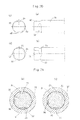
Figs. 4(a) and 4(b) are sectional views taken along line a-a ofFig. 1 , showing, respectively, an initial stage of insertion of a cutting tool, and the state after the cutting tool has been turned. -
Figs. 5(a) and 5(b) are sectional views taken along line b-b ofFig. 1 , showing, respectively, an initial stage of insertion of a cutting tool, and the state after the cutting tool has been turned. -
Fig. 6(a) is a partially cutaway front view of another embodiment; andFig. 6(b) is a sectional view taken along line X-X ofFig. 6(a) . -
Fig. 7 is a partially cutaway front view of still another embodiment. -
Fig. 8(a) is a partially cutaway front view of yet another embodiment;Fig. 8(b) is a right-hand side view thereof;Fig. 8(c) is a front view of a cutting tool thereof; andFig. 8(d) is a partial sectional view of a tool holder thereof, showing the state in which the cutting tool is mounted. -
Fig. 9(a) is a partially cutaway front view of a further embodiment;Fig. 9(b) is a partial front view of a cutting tool thereof; andFig. 9(c) is a partial sectional view of a tool holder thereof, showing the state in which the cutting tool is mounted. -
Fig. 10(a) is a partially cutaway front view of a still further embodiment;Fig. 10(b) is a partially cutaway front view of a cutting tool thereof; andFig. 10(c) is a partial sectional view of a tool holder thereof, showing the state in which the cutting tool is mounted. -
Fig. 11(a) is a partially cutaway front view of a yet further embodiment; andFigs. 11(b) and 11(c) shows how this embodiment operates. -
Fig. 12 is a partially cutaway front view of still another embodiment. -
Fig. 13(a) is a partial sectional front view of still another embodiment; andFig. 13(b) is a front view of a cutting tool thereof. -
Fig. 14(a) is a partially cutaway front view of a tool holder of a still further embodiment;Fig. 14(b) is a partial front view of a cutting tool thereof; andFig. 14(c) is a partial sectional front view of the tool holder thereof, showing the state in which the cutting tool is mounted. -
Fig. 15(a) is a partially cutaway front view of a tool holder of a still further embodiment;Fig. 15(b) is a partial sectional front view of a cutting tool thereof; andFig. 15(c) is a partial sectional front view of the tool holder thereof, showing the state in which the cutting tool is mounted. -
Fig. 16 is a partially cutaway front view of still another embodiment. -
Fig. 17(a) is a partially cutaway front view of a tool holder of still another embodiment;Fig. 17(b) is a left-hand side view of a cutting tool thereof; andFig. 17(c) is a partial front view of the cutting tool thereof. -
Fig. 18 is a partially cutaway front view of still another embodiment. -
Fig. 19(a) and 19(b) are plan views of cutting tools formed with different anti-pull-out grooves. -
Fig. 20(a) is a front view of a different cutting tool which can be fitted in the tool holder of any of the above embodiments;Fig. 20(b) is a plan view thereof;Fig. 20(c) is a left-hand side view ofFig. 20(a); and Fig. 20(d) is a left-hand side view ofFig. 20(b) . -
Figs. 21(a) and 21(b) show how cutting is performed using the cutting tool ofFigs. 20(a) to 20(d) , of whichFig. 21(a) shows an initial stage of insertion of the cutting tool, andFig. 21(b) shows after the cutting tool has been turned. -
Figs. 1 to 4 show a tool holder A embodying the present invention which includes ashank portion 1 detachably mounted to a spindle of a machining center, and an inverted conical chuck portion2 which is fixedly coupled to theshank portion 1 through a grip portion (V-flange portion) 3 to be gripped by a manipulator for an automatic tool changer (ATC). - The
shank portion 1 and thegrip portion 3 form an integral shank body, which is a separate member from thechuck portion 2. The integral shank body and thechuck portion 2 have respective fitting surfaces along which the shank body and thechuck portion 2 are joined together. A cylindrical fitting protrusion is formed on the fitting surface of thechuck portion 2, while a cylindrical fitting recess is formed in the fitting surface of the integral shank body such that a gap exists between the end surface of the cylindrical fitting protrusion and the inner end surface of the cylindrical fitting recess. Thechuck portion 2 and the integral shank portion are joined together by electron beam welding. But conversely, the cylindrical fitting protrusion and the cylindrical fitting recess may be formed on and in the fitting surfaces of the integral shank body and thechuck portion 2, respectively. - A cylindrical retaining bore 20 for retaining a
cutting tool 30 extends from the distal end of the chuck portion 2 (right-hand end inFig. 1 ) into the grip portion 3 (to be gripped by a manipulator) and has a center axis which coincides with the center axis of the tool holder. - The retaining bore 20 has a minimum diameter (diameter of the opening of the
bore 20 at the distal end of the chuck portion 2) which is slightly smaller than the diameter of thecutting tool 30 at itsinsert portion 31 to be inserted into and gripped by thechuck portion 2 such that the cuttingtool 30 is rigidly fixed in position in thechuck portion 2 by shrink fitting, in which thecutting tool 30 is inserted into the retaining bore 20 with thechuck portion 2 thermally expanded (and its retaining bore 20 radially expanded) by heating, and then thechuck portion 2 is allowed to cool down. In order to rigidly fix the cutting tool in position by shrink fitting, the chuck portion 2 (as well as theshank portion 1 and the grip portion 3 (to be gripped by a manipulator) is made e.g. of a material disclosed inPatent document 4. - Two anti-pull-out
protrusions 21 are provided on the inner wall of the portion of the retaining bore 20 formed in thechuck portion 2 at its portion near the fitting surface of thechuck portion 2 so as to be symmetrical to each other with respect to the axis of thechuck portion 2. Theprotrusions 21 are formed first by forming a rib extending the entire circumference of thebore 20 and having a semicircular cross-section, and then removing portions of the rib between its portions to be formed into the protrusions. The thus formedprotrusions 21 have apexes extending in a straight line in the direction perpendicular to the axial direction of the cutting tool and have a semicircular cross-section. The number ofsuch protrusions 21 may be three, four or more, providedsuch protrusions 21 are circumferentially equidistantly spaced apart from each other around the axis, and are equal in number to the number of the below-describedflat surfaces 32 formed on thecutting tool 30. - Two
anti-rotation protrusions 22 are provided on the inner wall of the portion of the retaining bore 20 formed in the integral shank portion (including theshank portion 2 and the grip portion 3) at its portion near its fitting surface so as to be symmetrical to each other with respect to the axis of the chuck portion (shank portion). Theanti-rotation protrusions 22 have a triangular cross-section along a plane perpendicular to the axial direction of the cutting tool, and are formed in a similar manner as theprotrusions 21. The number ofprotrusions 22 may be three, four or more, provided theprotrusions 22 are circumferentially equidistantly spaced from each other around the axis, and are equal in number to the number of the flat surfaces 32. Theprotrusions - The
protrusions 21 are circumferentially offset from the correspondingprotrusions 22 by 45 degrees around the axis of the tool. The tool holder is formed with aninternal thread 4 used to mount a coolant duct 6 (as shown inFig. 17 ). The tool holder carriesanti-slippage pins 5 configured to engage the end surface of a spindle, thereby preventing slippage (rotation) of the holder relative to the spindle. - The cutting
tool 30, which is to be attached to the tool holder A of this embodiment, is an end mill having a large diameter of e.g. 12 to 32 mm. Twoflat surfaces 32 are formed on the outer peripheral surface of theinsert portion 31 of thecutting tool 30 to be inserted into the retaining bore 20 at its end so as to be symmetrical to each other with respect to the axis of the tool. - The flat surfaces 32 are formed by cutting the outer peripheral surface of the
insert portion 31 of thecutting tool 30 along planes extending in the axial direction of the tool. Since the retaining bore 20 is cylindrical in shape, and theinsert portion 31 of the cutting tool is a columnar member, spaces S having a substantially crescent section are defined between the respectiveflat surfaces 32 and the inner wall of the retaining bore when theinsert portion 31 is inserted in the retaining bore 20. The cutting tool is further formed with agroove 33 having a semicircular cross-section and continuously and circumferentially extending along the rear ends of theflat surfaces 32, i.e. their ends closer to the distal end of thechuck portion 2 such thegroove 33 is coaxial with the cuttingtool 30. - When the
cutting tool 30 is inserted into the chuck portion 2 (of the tool holder A) as shown by the arrow inFig. 2 , since the openings of the substantially crescent spaces S defined between theflat surfaces 32 and the inner wall of the retaining bore are wide, one can easily recognize the angular relationship between theprotrusions 21 and the opening edges of the respective spaces. Thus, it is possible to easily turn thecutting tool 30 to the position where theprotrusions 21 are located at the centers of the respective spaces S, as shown inFig. 5(a) . - While the
protrusions 21 are moving along the respectiveflat surfaces 32, the end surface of the cutting tool insert portion reaches theprotrusions 21. Since theprotrusions 21 are angularly offset from therespective protrusions 22 by 45 degrees, eachprotrusion 22 is inserted into one end of the corresponding crescent space S. When the cutting tool is further pushed into the chuck portion, the end surface of the cutting tool insert portion abuts the deep end of the retaining bore 20. This determines the length of the portion of thecutting tool 30 protruding from the tool holder A. In this state, theprotrusions 21 are snugly fitted in thegroove 33 such that theprotrusions 21 can move in the length direction of thegroove 33 but not in the width direction of the groove (axial direction of the cutting tool 30), as shown inFig. 1 . - Since the
flat surfaces 32 serve as reference surfaces when fitting and locking in position the cuttingtool 30 in the tool holder A or when ejecting (removing) the cutting tool from the tool holder, symbols such as impressions are preferably provided on the end surface of thechuck portion 2 at positions corresponding to theprotrusions 21 on the retaining bore 20 such that theprotrusions - From the state shown in
Figs. 4 and 5(a) , when thecutting tool 30 is turned in the direction opposite to the cutting direction (clockwise direction in these figures), theprotrusions 21 are moved in thegroove 33 to the position shown inFig. 5(b) . In this state, theprotrusions 21 engage the side edges of thegroove 33, preventing thecutting tool 30 from coming out of the retaining bore 20 of thechuck portion 2. On the other hand, theprotrusions 22 move across the respective spaces S and are received in the opposite ends of the respective spaces S, as shown inFig. 4(b) , thereby preventing thecutting tool 30 from rotating in the cutting direction (rotational direction shown by the arrow inFig. 1 ) relative to thechuck portion 2. With theprotrusions 22 received in the other ends of the spaces S, theprotrusions 22 also serve to tightly clamp thecutting tool 30, thereby preventing chattering of thecutting tool 30. Since theanti-rotation protrusions 22 are complementary in shape to the other ends of the spaces S, which have a triangular section along a plane perpendicular to the axis of the cutting tool (as seen inFig. 4(b) ), when theprotrusions 22 are received in the other ends of the respective spaces S, theprotrusions 22 can effectively prevent rotation of the cutting tool. - In order to mount the
cutting tool 30 in position in the tool holder A, in the same manner as the conventional arrangement, the tool holder A (chuckportion 2 and a portion of thegrip portion 3 to be gripped by a manipulator) is thermally expanded by heating to radially expand the retaining bore 20. - When the tool holder A cools down thereafter, the cutting
tool 30 is rigidly fitted in position in the tool holder A, with theprotrusions 21 engaging the side edges of thegroove 33 and theprotrusions 22 received in ends of the spaces S such that the cuttingtool 30 is positively prevented from being pulled out of thechuck portion 2 and also prevented from rotating relative to thechuck portion 2. This increases the gripping force. - To remove the
cutting tool 30 from the tool holder A, the tool holder A is thermally expanded heating to radially expand the retaininghole 20, and then thecutting tool 30 is turned in the opposite direction to the direction in which the tool is turned to fit the tool in the tool holder, and pulled out. - The circumferential offset angle between the
protrusions protrusions protrusions 22 received in the respective spaces S, when the cutting tool A is turned, theprotrusions 22 are configured to be received in the corresponding ends of the spaces S, thus preventing rotation of the cutting tool A. -
Fig. 6 shows another embodiment, in which instead of theprotrusions bore 20. Thepins 25 are columnar members each inserted in ahole 25a extending through thechuck portion 2.Screws 25b are in threaded engagement in eachhole 25a at both ends of thehole 25a to prevent thepin 25 from being pulled out of thehole 25a. - When the
cutting tool 30 is inserted into the retaining bore 20 of the tool holder A (chuck portion 2), thepins 25 pass through the spaces S while sliding on theflat surfaces 32 and are received in thegroove 33. When, thereafter, the cuttingtool 30 is rotated, thepins 25 leave theflat surfaces 32 and are received in thegroove 33, thus preventing thecutting tool 30 from being pulled out of thechuck portion 2. - The
groove 33 may not extend the entire circumference but have circumferential ends. In this case, by bringing thepins 25 into abutment with the respective circumferential ends, thepins 25 ca prevent thecutting tool 30 not only from being pulled out of thechuck portion 2 but also from being rotating relative to thechuck portion 2. Also, even without thegroove 33, the cuttingtool 30 is prevented from rotating relative to thechuck portion 2 due to the engagement of thepins 25 with theflat surfaces 32, and thecutting tool 30 is also prevented from being pulled out of thechuck portion 2 because thepins 25 are received in the spaces S. - Further, in this embodiment, since the
pins 25 are inserted into theholes 25a from the outer peripheral surface of thechuck portion 2, thepins 25 can be easily inserted into theholes 25a, so that thechuck portion 2 and theshank portion 1 need not be separate members but may form an integral body. Thepins 25 may not be in the shape of circular columns provided they can slide on the flat surfaces 32. For example, thepins 25 may be in the shape of polygonal (such as square) columns. - In the embodiment of
Fig. 1 , even without theprotrusions 21 and thegroove 33, with theprotrusions 22 received in the spaces between the inner wall of the retaining bore and theflat surfaces 32, the cuttingtool 30 is not only prevented from rotating relative to thechuck portion 2 but prevented, to a certain extent, from being pulled out of thechuck portion 2. -
Fig. 7 shows still another embodiment, in which the tool holder A includes a one-way clutch 40 provided on the inner wall of the retaining bore 20 of thechuck portion 2 to prevent rotation of thecutting tool 30 in the cutting direction relative to thechuck portion 2. In this arrangement, when thecutting tool 30 is inserted into the retaining bore 20,rollers 41 of the one-way clutch 40 abut the outer peripheral surface of theinsert portion 31 of thecutting tool 30. The one-way clutch 40 is configured to allow rotation of thecutting tool 30 relative to the tool holder A (chuck portion 2) in the direction opposite to the cutting direction, and prevent rotation of thecutting tool 30 relative to thechuck portion 2 due to engagement ofrollers 41 between the retaining bore 20 and thecutting tool 30. The one-way clutch 40 may be a known one such as disclosed inPatent document - In this embodiment, the one-way clutch 40 is fitted in an annular recess formed in the inner wall of the retaining bore 20. Since this recess can be formed easily, the
chuck portion 2 and theshank portion 1 need not be separate members but may form an integral body. - In this embodiment, the above-mentioned
flat surfaces 32 may be formed on thecutting tool 30 such that axially elongated protrusions half embedded in the inner wall of the retaining bore 20, such as therollers 41, can be received in the spaces S defined by theflat surfaces 32, when thecutting tool 30 rotates, the protrusions are received in corresponding ends of the spaces S, thereby preventing rotation of the cutting tool. -
Figs. 8(a) to 8(d) show yet another embodiment, in which the tool holder A has none of theprotrusions flat surfaces 32 as used in the previous embodiments. Instead, astopper 45 is screwed to the end surface of thechuck portion 2 from which the cutting tool is inserted into the retaining bore 20 so as to engage agroove 34 of thecutting tool 30. - The
stopper 45 is shown to be composed of two split halves, but may be composed of more than two, such as three or four, split pieces. In any of such cases, the split pieces are preferably equal in size (weight) so that the tool holder can rotate in a balanced manner. In this case, some of the plurality of split pieces forming thestopper 45 may be omitted, and the remaining split pieces may be arranged circumferentially equidistantly spaced apart from each other. For example, two of the four split pieces forming thestopper 45 may be omitted, and the remaining two split pieces may be arranged circumferentially equidistantly spaced apart from each other. - In this embodiment, after fitting the
cutting tool 30 in the retaining bore 20, by fixing thestopper 45 in position with screws, thestopper 45 is fitted in the groove (step) 34, as shown inFig. 8(d) . This prevents thecutting tool 30 from being pulled out of thechuck portion 2. Thegroove 34 may extend only a part of the entire circumference, for example, may be in the form of aflat surface 32, thestopper 45 also serves to prevent rotation of the cutting tool by abutting one of the circumferential ends of thegroove 34. In this case, the bore of the stopper 45 (through which thecutting tool 30 is inserted) is shaped complementary to the groove 34 (such as a circular shape with its circumference partially removed). -
Figs. 9 and10 show further embodiments, in which instead of theprotrusions flat surfaces 32, as used in the previous embodiments, the tool holder A has aninternal thread 46 or anexternal thread 47 configured to be brought into threaded engagement with anexternal thread 35 or aninternal thread 36, respectively, formed at the end of thecutting tool 30 from which the cutting tool is inserted into the tool holder. Theinternal thread 46 or theexternal thread 47 are formed on acoolant duct 7 or 7', which is an extension of thecoolant duct 6 extended from the distal end of thecoolant duct 6 into the retaining bore 20. - In these embodiments, as shown in
Fig. 9(c) and10(c) , when thecutting tool 30 is fitted in the retaining bore 20, by bringing thethread thread tool 30 is prevented from being pulled out of thechuck portion 2. These threads are brought into threaded engagement with each other by threading thecoolant duct 7 or 7' onto or into the shank of the cutting tool (shown inFig. 1 ) after fitting thecutting tool 30 in the tool holder A by shrink fitting. If the threads are brought into engagement with each other by threading thecoolant duct 7 or 7' in the direction opposite to the cutting direction, it is also possible to prevent rotation of the cutting tool. - In any of the above embodiments,
pins 22a may be used instead of theprotrusions 22 to prevent rotation of the cutting tool. In particular, in the embodiment ofFig. 11 , which is a modification of the embodiment ofFig. 1 , pins 22a are provided at the same position as theprotrusions 22 of the embodiment ofFig. 1 , by threading, fitting or by any other suitable means, so as to protrude from the inner wall of thebore 20. With this arrangement, in the same manner as in the embodiment ofFig. 1 , when thecutting tool 30 is inserted into the retaining bore 20 of the chuck portion 2 (tool holder A), with theflat surfaces 32 corresponding in position to theprotrusions 21 and thepins 22a, until the end surface of the insert portion of the cutting tool abuts the inner wall of the retaining bore 20, and thecutting tool 30 is turned, theprotrusions 21 move in thegroove 33 and engage the side edges of thegroove 33, thus preventing thecutting tool 30 from being pulled out of the chuck portion 2 (retaining bore 20). Simultaneously, thepins 22a move in the spaces S and are received in corresponding ends of the spaces S (fromFig. 11(b) to 11(c) ), thus preventing rotation of thecutting tool 30 relative to thechuck portion 2. - In the embodiments of
Figs. 6 ,8 ,9 and10 , too, thepins 22a may be provided on the fitting surface of the integral shank body including theshank portion 1 so as to protrude from the fitting surface, as shown inFigs. 12 ,13 ,14 and15 , respectively, to prevent rotation of the cutting tool in the same manner as above. In the embodiment ofFig. 12 , the cuttingtool 30 is the one shown inFig. 3 and thus has theflat surfaces 32 and thegroove 33. In the embodiment ofFig. 13 , the cuttingtool 30 hasflat surfaces 32 shown inFig. 13(b) . In the embodiments ofFigs. 14 and15 , the cuttingtool 30 hasflat surfaces 32 shown in either ofFigs. 14(b) and15(b) . - In the embodiment of
Fig. 13 , after inserting thecutting tool 30 into the retaining bore 20 of thechuck portion 2, and turning thecutting tool 30 until thepins 22a are received in corresponding ends of the spaces between the inner wall of the retaining bore 20 and theflat surfaces 32, the cuttingtool 30 may be fixed to thechuck portion 2 by shrink fitting, and then thestopper 45 may be mounted. Alternatively, after thepins 22a have been received in ends of the above spaces, thestopper 45 may be mounted and then cuttingtool 30 may be fixed to thechuck portion 2 by shrink fitting. - In the embodiment of
Fig. 7 , as shown inFig. 16 , if theprotrusions 21 is formed on the integral shank body including theshank portion 1, and as the cuttingtool 30, the one shown inFig. 3 , which has theflat surfaces 32 and thegroove 33, is used, it is possible to prevent the cutting tool from being pulled out of the tool holder in the same manner as above. In this arrangement, theprotrusions 21 may be replaced by thepins 25 shown inFig. 6 . - Further, in order to prevent the
cutting tool 30 from being pulled out of the tool holder, as shown inFig. 17 ,pins 21a may be screwed into the chuck portion from its outer peripheral surface as shown, similar to conventional side locking functions. As shown inFigs. 17(b) and 17(c) , the cuttingtool 30 is formed withflat surfaces 32a which the distal ends of thepins 21a are configured to abut. In this embodiment, the pins 22s, shown, may be used to prevent rotation of the cutting tool, orprotrusions - The
shank portion 1 may not be of the HSK type as in the above embodiments, but may be of any other type such as the BT type as shown inFig. 17 . As also shown inFig. 17 , theanti-rotation protrusions 22 may be formed on the inner wall of the portion of the retaining bore 20 formed in thechuck portion 2. - The cross-sectional shape of the
groove 33 is not limited to a circular arc but may be e.g. a triangle as shown inFig. 19(a) or a trapezoid as shown inFig. 19(b) . The sectional shape of theprotrusions 21, which is adapted to engage in thegroove 33, and the sectional shape of theprotrusions 22, which are received in ends of the spaces S, are not limited, provided theprotrusions 21 can be snugly fitted in thegroove 33 such that theprotrusions 21 are movable only in the length direction of the groove and not movable in the width direction of the groove 33 (axial direction of the cutting tool 30). - The
groove 33 may not extend the entire circumference but may extend only up to an intermediate point in the direction opposite to the cutting direction as shown inFig. 20 . With this arrangement, when one of theprotrusions 21 engages the end of thegroove 33, rotation of the cutting tool is stopped. This eliminates the necessity of theanti-rotation protrusions 22. In this arrangement, if thegroove 33 has e.g. a circular arc or triangular cross-section and is designed such that its depth and width gradually decrease toward its end, when thecutting tool 30 is inserted in the retaining bore 20 of thechuck portion 2 and is turned in the cutting direction, from the state ofFig. 21(a) to the state ofFig. 21(b) , one of theprotrusions 21 is more tightly pressed against the inner wall of the groove as it moves toward the end of thegroove 33, thus effectively preventing rattling of thecutting tool 30. But even if the depth and width of thegroove 33 is constant up to its end, this arrangement can still prevent the cutting tool from being pulled out or from rotating. - It has been confirmed that while heavy cutting is performed with large bending force applied to the
cutting tool 30, slippage occurs in the cutting direction between the columnar insert portion of thecutting tool 30 and the cylindrical retaininghole 20 of thechuck portion 2, which is gripping thecutting tool 30. If it is known that the tool system is used in such heavy cutting, theanti-rotation protrusions anti-rotation protrusions 22 ofFig. 4 may be positioned such that cutting is performed with theprotrusions 22 received between the inner wall of the retaining bore 20 and the flat surfaces 32. If the one-way clutch 40 is used, it is positioned to prevent rotation in the cutting direction. - The tool holder according to the present invention is used not only in 5-axis control, but also in 2-axis control, 3-axis control, 5-axis control, or more than 5-axis control.
- The above embodiments are mere examples in every respect, and the present invention is not limited to these embodiments. Rather, it should be understand that the present invention is interpreted as covering what is shown by claims and any equivalents of the claimed elements.
-
- 1. Shank portion
- 2. Chuck portion
- 3. Grip portion (to be gripped by a manipulator)
- 20. Cutting tool retaining bore of the chuck portion
- 21, 25. Anti-pull-out protrusion
- 22, 22a. Anti-rotation protrusion
- 30. Cutting tool
- 31. Insert portion of the cutting tool (to be inserted into the retaining bore)
- 32. Flat surface
- 33. Circumferential groove
- 34. Anti-pull-out groove
- 35. External thread
- 36. Internal thread
- 40. One-way clutch
- 41. Rollers of the one-way clutch
- 45. Anti-pull-out stopper
- 46. Internal thread
- 47. External thread
- A. Tool holder
- S. Space
Claims (4)
- A shrink fit tool holder comprising a shank portion (1) which can be detachably mounted to a machine tool, and a chuck portion (2) configured to hold a cutting tool (30) by shrink fitting and formed with a cylindrical retaining bore (20), wherein the cutting tool (30) comprises a columnar insert portion (31) which can be inserted into the retaining bore (20) and has an outer peripheral surface formed with a flat surface (32) lying on a plane extending in an axial direction of the cutting tool (30), and extending from a distal end of the insert portion (31) of the cutting tool (30), and with a groove (33) continuous with the flat surface (32) and extending in a circumferential direction of the cutting tool (30),
characterized in that an anti-pull-out protrusion (21) and an anti-rotation protrusion (22) are provided on an inner wall of the retaining bore (20) with the anti-pull-out protrusion (21) spaced from the anti-rotation protrusion (22) in the axial direction of the cutting tool (30),
wherein the tool holder A is configured such that when the cutting tool (30) is inserted into the retaining bore (20), the anti-pull-out protrusion (21) can pass through a space (S) defined between the flat surface (32) and the inner wall of the retaining bore (20) and can be received in the groove (33), and when, thereafter, the cutting tool (30) is turned about an axis of the cutting tool (30) relative to the chuck portion (2), the anti-pull-out protrusion (21) moves in a length direction of the groove (33) until the anti-pull-out protrusion (21) engages side edges of the groove (33), thereby preventing the cutting tool (30) from being pulled out of the chuck portion (2), and
wherein the tool holder (A) is further configured such that when the anti-pull-out protrusion (21) is received in the groove (33), the anti-rotation protrusion (22) is located in the space (S), and when, thereafter, the cutting tool (30) is turned about the axis of the cutting tool (30) relative to the chuck portion (2), the anti-rotation protrusion is received between the flat surface (32) and the inner wall of the retaining bore (20) at one end of the space (S), thereby preventing rotation of the cutting tool (30) relative to the chuck portion (2). - The shrink fit tool holder of claim 1, wherein the anti-rotation protrusion (22) has a triangular section along a plane perpendicular to the axial direction of the cutting tool such that an apex of the triangular section is directed at the axis of the cutting tool.
- The shrink fit tool holder of claim 1, wherein instead of the anti-rotation protrusions (22), a one-way clutch (40) provided on the inner wall of the retaining bore (20) of the chuck portion (2) to extend in a circumferential direction of the retainer bore (20) so as to be axially spaced apart from the anti-pull-out protrusion (21),
wherein the tool holder is configured such that when the cutting tool (30) is inserted into the retaining bore (20), rollers (41) of the one-way clutch (40) abut the outer peripheral surface of insert portion (31) of the cutting tool (30), whereby the one-clutch (40) permits rotation of the cutting tool (30) relative to the chuck portion (2) in a direction opposite to a cutting direction. - The shrink fit tool holder of any of claims 1 to 3, wherein the tool holder (A) is split into two bodies (1 and 2) between the anti-pull-out protrusion (21) and the anti-rotation protrusion (22); at a position closer to the shank portion (1) than the anti-pull-out protrusion (21), or between the one-way clutch (40) and the anti-pull-out protrusion (21), and wherein the two bodies (1 and 2) are joined together.
Priority Applications (1)
| Application Number | Priority Date | Filing Date | Title |
|---|---|---|---|
| EP15163929.1A EP2929964A1 (en) | 2011-08-22 | 2012-08-03 | Shrink fit tool holder |
Applications Claiming Priority (2)
| Application Number | Priority Date | Filing Date | Title |
|---|---|---|---|
| JP2011180671 | 2011-08-22 | ||
| PCT/JP2012/069807 WO2013027558A1 (en) | 2011-08-22 | 2012-08-03 | Shrink fit tool holder |
Related Child Applications (2)
| Application Number | Title | Priority Date | Filing Date |
|---|---|---|---|
| EP15163929.1A Division EP2929964A1 (en) | 2011-08-22 | 2012-08-03 | Shrink fit tool holder |
| EP15163929.1A Division-Into EP2929964A1 (en) | 2011-08-22 | 2012-08-03 | Shrink fit tool holder |
Publications (3)
| Publication Number | Publication Date |
|---|---|
| EP2749367A1 true EP2749367A1 (en) | 2014-07-02 |
| EP2749367A4 EP2749367A4 (en) | 2015-01-14 |
| EP2749367B1 EP2749367B1 (en) | 2017-10-11 |
Family
ID=47746309
Family Applications (2)
| Application Number | Title | Priority Date | Filing Date |
|---|---|---|---|
| EP12825769.8A Active EP2749367B1 (en) | 2011-08-22 | 2012-08-03 | Shrink fit tool holder |
| EP15163929.1A Withdrawn EP2929964A1 (en) | 2011-08-22 | 2012-08-03 | Shrink fit tool holder |
Family Applications After (1)
| Application Number | Title | Priority Date | Filing Date |
|---|---|---|---|
| EP15163929.1A Withdrawn EP2929964A1 (en) | 2011-08-22 | 2012-08-03 | Shrink fit tool holder |
Country Status (7)
| Country | Link |
|---|---|
| US (1) | US9254525B2 (en) |
| EP (2) | EP2749367B1 (en) |
| JP (1) | JP5571253B2 (en) |
| CN (1) | CN103781579B (en) |
| ES (1) | ES2646765T3 (en) |
| TW (1) | TWI571352B (en) |
| WO (1) | WO2013027558A1 (en) |
Cited By (2)
| Publication number | Priority date | Publication date | Assignee | Title |
|---|---|---|---|---|
| EP2797708A1 (en) | 2011-12-27 | 2014-11-05 | Franz Haimer Maschinenbau KG | Tool holder and method for producing a tool receiving portion for such a tool holder |
| WO2016173578A3 (en) * | 2015-04-29 | 2017-01-26 | Gühring KG | Clamping device, method for a clamping device and use for a clamping device |
Families Citing this family (14)
| Publication number | Priority date | Publication date | Assignee | Title |
|---|---|---|---|---|
| KR101136382B1 (en) * | 2009-12-08 | 2012-04-18 | 한국기계연구원 | tool holder using shape memory alloy and tool holding method |
| DE102014223036A1 (en) * | 2014-11-12 | 2016-05-12 | Robert Bosch Gmbh | TOOL AND METHOD FOR TREATING A WORKPIECE WITH A TOOL ELEMENT OF A TOOL |
| US10010945B2 (en) | 2015-06-02 | 2018-07-03 | The Boeing Company | Receivers and methods for forming such receivers |
| US10071438B2 (en) | 2015-06-02 | 2018-09-11 | The Boeing Company | Methods of forming shanks |
| JP5923646B1 (en) * | 2015-06-12 | 2016-05-24 | 株式会社日研工作所 | Shrink-fitting tool holder and cutter chucking structure |
| DE102016005081A1 (en) * | 2016-04-27 | 2017-11-02 | KARL SCHÜSSLER GmbH & Co. KG | shrink fit chucks |
| WO2018060987A1 (en) | 2016-09-29 | 2018-04-05 | Iscar Ltd. | Rotating tool having a tool anchorage arrangement following a stepped path and method of positioning said tool |
| EP3330025B1 (en) * | 2016-11-30 | 2023-08-16 | Seco Tools Ab | Cutting assembly with multiple cutting tools for milling |
| US9981320B1 (en) * | 2017-01-20 | 2018-05-29 | Ching-Ting Chen | Shrink fit tool holder assembly |
| JP6944302B2 (en) * | 2017-08-04 | 2021-10-06 | 三菱重工業株式会社 | Cutting tools |
| JP6762588B1 (en) * | 2019-09-04 | 2020-09-30 | 九州精密工業株式会社 | Skying cutter |
| DE102019134596A1 (en) | 2019-12-16 | 2021-06-17 | Kennametal Inc. | Rotary cutting tool and tool assembly |
| US11819928B2 (en) | 2020-10-14 | 2023-11-21 | Iscar, Ltd. | Insert holder having insert receiving recess with insert orientation projection and cutting tool |
| US11524341B2 (en) * | 2021-05-12 | 2022-12-13 | Techniks, LLC | Method and apparatus for retaining a tool in a tool holder with defined contact surfaces |
Citations (4)
| Publication number | Priority date | Publication date | Assignee | Title |
|---|---|---|---|---|
| US2801860A (en) * | 1956-10-30 | 1957-08-06 | Metal Cutting Tools Inc | Double-acting spring for pin drive and clutch drive counterbores |
| JPS53139683U (en) * | 1977-04-11 | 1978-11-04 | ||
| JP2002355727A (en) * | 2001-05-30 | 2002-12-10 | Daishowa Seiki Co Ltd | Shrinkage-fitted tool holder |
| DE112008000350T5 (en) * | 2007-02-08 | 2010-02-18 | Seco Tools Ab | Tool with shrink fit and with mechanical holding part and method for mounting a tool to a tool holder |
Family Cites Families (30)
| Publication number | Priority date | Publication date | Assignee | Title |
|---|---|---|---|---|
| US271143A (en) * | 1883-01-23 | smith | ||
| US965131A (en) * | 1908-02-29 | 1910-07-19 | Donald M Bliss | Shaft-coupling. |
| US1424743A (en) * | 1920-03-19 | 1922-08-01 | Eclipse Interchangeable Counte | Counterboring tool |
| US1413280A (en) * | 1921-04-28 | 1922-04-18 | Eclipse Interchangeable Counte | Locking device for boring or other tools |
| US1809553A (en) * | 1926-03-25 | 1931-06-09 | Edith P Graul | Tool holder |
| US2540937A (en) * | 1947-03-15 | 1951-02-06 | Ralph A Edens | Toolholder |
| US2731273A (en) * | 1955-05-23 | 1956-01-17 | Falcon Tool Company | Tool holders |
| US3171666A (en) * | 1962-12-14 | 1965-03-02 | Erickson Tool Co | Positive drive chuck |
| CH449382A (en) * | 1966-05-02 | 1967-12-31 | Schrepfer Rudolf | Tool holder for tools to be attached to it with a bayonet lock |
| FR2036142A5 (en) * | 1969-03-05 | 1970-12-24 | Sud Aviation | |
| US3679220A (en) * | 1970-03-23 | 1972-07-25 | Portage Machine Co | Quick change tool holder |
| JPS5139895Y2 (en) * | 1971-12-01 | 1976-09-29 | ||
| JPS53139683A (en) | 1977-05-11 | 1978-12-06 | Idearisaachi Yuugen | Plastic film |
| US4361196A (en) * | 1980-07-11 | 1982-11-30 | Carmet Company | Roof bit coupling |
| JPS6116204U (en) * | 1984-06-29 | 1986-01-30 | 大昭和精機株式会社 | combination lock holder |
| JPH0526264A (en) | 1991-07-26 | 1993-02-02 | Ntn Corp | One-way clutch |
| JPH05126170A (en) | 1991-11-01 | 1993-05-21 | Jatco Corp | One-way clutch and automatic transmission using the same |
| US5597275A (en) * | 1995-03-28 | 1997-01-28 | Hogan; Scott H. | Tool with changeable working tip |
| DE29705575U1 (en) * | 1997-03-27 | 1998-04-23 | Pokolm Franz Josef | Machining tool |
| JP3932216B2 (en) | 1997-08-11 | 2007-06-20 | 株式会社Mstコーポレーション | Shrink-fit tool holder |
| JP3697371B2 (en) | 1999-09-07 | 2005-09-21 | 株式会社日研工作所 | End mill chucking structure |
| WO2001007186A1 (en) * | 1999-07-21 | 2001-02-01 | Black & Decker Inc. | Power drivable chuck |
| SE9904752A (en) * | 1999-12-22 | 2000-01-24 | Sandvik Ab | Toolholder and insert arrangement with a shrink fit coupling |
| JP2002035527A (en) * | 2000-07-26 | 2002-02-05 | Japan Atom Energy Res Inst | Gas separation apparatus |
| US7077608B2 (en) * | 2004-04-22 | 2006-07-18 | Parlec, Inc. | System for mounting a machine tool in a holder |
| US7815433B2 (en) * | 2005-06-10 | 2010-10-19 | Tti Turner Technology Instruments Inc. | Adjustable tool drive arrangement |
| DE102006062973C5 (en) * | 2006-04-10 | 2020-03-05 | Franz Haimer Maschinenbau Kg | System of tool holder with a cylindrical tool holder in the form of a collet chuck and tool |
| DE102007012487B4 (en) * | 2007-03-15 | 2016-12-15 | Franz Haimer Maschinenbau Kg | toolholder |
| JP4781329B2 (en) | 2007-08-22 | 2011-09-28 | 株式会社Mstコーポレーション | Tool holder |
| US8033766B2 (en) * | 2008-05-09 | 2011-10-11 | Kennametal Inc. | Tool holder with ball clamping mechanism |
-
2012
- 2012-08-03 EP EP12825769.8A patent/EP2749367B1/en active Active
- 2012-08-03 CN CN201280040940.2A patent/CN103781579B/en active Active
- 2012-08-03 US US14/239,805 patent/US9254525B2/en active Active
- 2012-08-03 WO PCT/JP2012/069807 patent/WO2013027558A1/en active Application Filing
- 2012-08-03 ES ES12825769.8T patent/ES2646765T3/en active Active
- 2012-08-03 EP EP15163929.1A patent/EP2929964A1/en not_active Withdrawn
- 2012-08-03 JP JP2013529950A patent/JP5571253B2/en active Active
- 2012-08-21 TW TW101130297A patent/TWI571352B/en active
Patent Citations (4)
| Publication number | Priority date | Publication date | Assignee | Title |
|---|---|---|---|---|
| US2801860A (en) * | 1956-10-30 | 1957-08-06 | Metal Cutting Tools Inc | Double-acting spring for pin drive and clutch drive counterbores |
| JPS53139683U (en) * | 1977-04-11 | 1978-11-04 | ||
| JP2002355727A (en) * | 2001-05-30 | 2002-12-10 | Daishowa Seiki Co Ltd | Shrinkage-fitted tool holder |
| DE112008000350T5 (en) * | 2007-02-08 | 2010-02-18 | Seco Tools Ab | Tool with shrink fit and with mechanical holding part and method for mounting a tool to a tool holder |
Non-Patent Citations (1)
| Title |
|---|
| See also references of WO2013027558A1 * |
Cited By (6)
| Publication number | Priority date | Publication date | Assignee | Title |
|---|---|---|---|---|
| EP2797708A1 (en) | 2011-12-27 | 2014-11-05 | Franz Haimer Maschinenbau KG | Tool holder and method for producing a tool receiving portion for such a tool holder |
| EP2797708B1 (en) * | 2011-12-27 | 2016-11-02 | Franz Haimer Maschinenbau KG | Tool holder and method for producing a tool receiving portion for such a tool holder |
| EP3150311A1 (en) * | 2011-12-27 | 2017-04-05 | Franz Haimer Maschinenbau KG | Tool holder and tensioning system with such a tool holder and method for producing a tool holder for a such tool holder |
| US9943912B2 (en) | 2011-12-27 | 2018-04-17 | Franz Haimer Maschinenbau Kg | Tool holder and method for producing a tool receiving portion for such a tool holder |
| US10967437B2 (en) | 2011-12-27 | 2021-04-06 | Franz Haimer Maschinenbau Kg | Tool holder and clamping system |
| WO2016173578A3 (en) * | 2015-04-29 | 2017-01-26 | Gühring KG | Clamping device, method for a clamping device and use for a clamping device |
Also Published As
| Publication number | Publication date |
|---|---|
| TWI571352B (en) | 2017-02-21 |
| ES2646765T3 (en) | 2017-12-15 |
| US9254525B2 (en) | 2016-02-09 |
| EP2749367A4 (en) | 2015-01-14 |
| JP5571253B2 (en) | 2014-08-13 |
| US20140210169A1 (en) | 2014-07-31 |
| CN103781579A (en) | 2014-05-07 |
| EP2929964A1 (en) | 2015-10-14 |
| CN103781579B (en) | 2017-03-01 |
| TW201318765A (en) | 2013-05-16 |
| EP2749367B1 (en) | 2017-10-11 |
| JPWO2013027558A1 (en) | 2015-03-19 |
| WO2013027558A1 (en) | 2013-02-28 |
Similar Documents
| Publication | Publication Date | Title |
|---|---|---|
| EP2749367B1 (en) | Shrink fit tool holder | |
| JP5011366B2 (en) | Tool holder and method for assembling the tool holder | |
| EP2391471B1 (en) | Cutting tool having a clamping mechanism | |
| KR20180016342A (en) | Tapered end mill and cutting head | |
| JP2010536593A (en) | Drill chuck | |
| WO2007086112A1 (en) | Shrink-fit tool unit, tool holder used for the shrink-fit tool unit, and rotary tool | |
| JP4768640B2 (en) | Shrink-fit tool holder | |
| JP4758296B2 (en) | Tool holder | |
| US20220410280A1 (en) | Cutting tool assembly | |
| DE202012013200U1 (en) | Shrink fit tool holder | |
| JP5923646B1 (en) | Shrink-fitting tool holder and cutter chucking structure | |
| EP3495080B1 (en) | A tool body assembly, a tool assembly and a machine | |
| JP2010179447A (en) | Cylindrical drilling tool | |
| JP5368965B2 (en) | Valve seat machining tool | |
| JP2016001032A (en) | Adjustment screw, operating tool, and cutting tool | |
| US6004083A (en) | System for mounting a chuck device to a rotary power tool | |
| JP2577907B2 (en) | Tool holder | |
| JP6432704B1 (en) | Cutting insert and rotary cutting tool | |
| EP2719488B1 (en) | Toolholder with elastic finger clamping arrangement and cutting tool having a toolholder and a replaceable cutting head | |
| JP2019181681A (en) | Cutting insert and rotary cutting tool | |
| JP4212990B2 (en) | Drilling tool | |
| JP4896659B2 (en) | Shrink-fit tool holder | |
| JP4586512B2 (en) | Tool fastening mechanism | |
| JP2013202749A (en) | Boring bar | |
| JP2019089184A (en) | Tool holder |
Legal Events
| Date | Code | Title | Description |
|---|---|---|---|
| PUAI | Public reference made under article 153(3) epc to a published international application that has entered the european phase |
Free format text: ORIGINAL CODE: 0009012 |
|
| 17P | Request for examination filed |
Effective date: 20140317 |
|
| AK | Designated contracting states |
Kind code of ref document: A1 Designated state(s): AL AT BE BG CH CY CZ DE DK EE ES FI FR GB GR HR HU IE IS IT LI LT LU LV MC MK MT NL NO PL PT RO RS SE SI SK SM TR |
|
| DAX | Request for extension of the european patent (deleted) | ||
| A4 | Supplementary search report drawn up and despatched |
Effective date: 20141212 |
|
| RIC1 | Information provided on ipc code assigned before grant |
Ipc: B23B 31/113 20060101ALI20141208BHEP Ipc: B23B 31/117 20060101AFI20141208BHEP Ipc: B23B 31/00 20060101ALI20141208BHEP |
|
| 17Q | First examination report despatched |
Effective date: 20151106 |
|
| GRAP | Despatch of communication of intention to grant a patent |
Free format text: ORIGINAL CODE: EPIDOSNIGR1 |
|
| INTG | Intention to grant announced |
Effective date: 20170329 |
|
| GRAS | Grant fee paid |
Free format text: ORIGINAL CODE: EPIDOSNIGR3 |
|
| GRAA | (expected) grant |
Free format text: ORIGINAL CODE: 0009210 |
|
| AK | Designated contracting states |
Kind code of ref document: B1 Designated state(s): AL AT BE BG CH CY CZ DE DK EE ES FI FR GB GR HR HU IE IS IT LI LT LU LV MC MK MT NL NO PL PT RO RS SE SI SK SM TR |
|
| REG | Reference to a national code |
Ref country code: GB Ref legal event code: FG4D |
|
| REG | Reference to a national code |
Ref country code: CH Ref legal event code: EP Ref country code: CH Ref legal event code: NV Representative=s name: BOVARD AG PATENT- UND MARKENANWAELTE, CH |
|
| REG | Reference to a national code |
Ref country code: IE Ref legal event code: FG4D |
|
| REG | Reference to a national code |
Ref country code: AT Ref legal event code: REF Ref document number: 935577 Country of ref document: AT Kind code of ref document: T Effective date: 20171115 |
|
| REG | Reference to a national code |
Ref country code: DE Ref legal event code: R096 Ref document number: 602012038505 Country of ref document: DE |
|
| REG | Reference to a national code |
Ref country code: ES Ref legal event code: FG2A Ref document number: 2646765 Country of ref document: ES Kind code of ref document: T3 Effective date: 20171215 |
|
| REG | Reference to a national code |
Ref country code: NL Ref legal event code: MP Effective date: 20171011 |
|
| REG | Reference to a national code |
Ref country code: LT Ref legal event code: MG4D |
|
| REG | Reference to a national code |
Ref country code: AT Ref legal event code: MK05 Ref document number: 935577 Country of ref document: AT Kind code of ref document: T Effective date: 20171011 |
|
| PG25 | Lapsed in a contracting state [announced via postgrant information from national office to epo] |
Ref country code: NL Free format text: LAPSE BECAUSE OF FAILURE TO SUBMIT A TRANSLATION OF THE DESCRIPTION OR TO PAY THE FEE WITHIN THE PRESCRIBED TIME-LIMIT Effective date: 20171011 |
|
| PG25 | Lapsed in a contracting state [announced via postgrant information from national office to epo] |
Ref country code: SE Free format text: LAPSE BECAUSE OF FAILURE TO SUBMIT A TRANSLATION OF THE DESCRIPTION OR TO PAY THE FEE WITHIN THE PRESCRIBED TIME-LIMIT Effective date: 20171011 Ref country code: NO Free format text: LAPSE BECAUSE OF FAILURE TO SUBMIT A TRANSLATION OF THE DESCRIPTION OR TO PAY THE FEE WITHIN THE PRESCRIBED TIME-LIMIT Effective date: 20180111 Ref country code: LT Free format text: LAPSE BECAUSE OF FAILURE TO SUBMIT A TRANSLATION OF THE DESCRIPTION OR TO PAY THE FEE WITHIN THE PRESCRIBED TIME-LIMIT Effective date: 20171011 Ref country code: FI Free format text: LAPSE BECAUSE OF FAILURE TO SUBMIT A TRANSLATION OF THE DESCRIPTION OR TO PAY THE FEE WITHIN THE PRESCRIBED TIME-LIMIT Effective date: 20171011 |
|
| PG25 | Lapsed in a contracting state [announced via postgrant information from national office to epo] |
Ref country code: AT Free format text: LAPSE BECAUSE OF FAILURE TO SUBMIT A TRANSLATION OF THE DESCRIPTION OR TO PAY THE FEE WITHIN THE PRESCRIBED TIME-LIMIT Effective date: 20171011 Ref country code: IS Free format text: LAPSE BECAUSE OF FAILURE TO SUBMIT A TRANSLATION OF THE DESCRIPTION OR TO PAY THE FEE WITHIN THE PRESCRIBED TIME-LIMIT Effective date: 20180211 Ref country code: RS Free format text: LAPSE BECAUSE OF FAILURE TO SUBMIT A TRANSLATION OF THE DESCRIPTION OR TO PAY THE FEE WITHIN THE PRESCRIBED TIME-LIMIT Effective date: 20171011 Ref country code: GR Free format text: LAPSE BECAUSE OF FAILURE TO SUBMIT A TRANSLATION OF THE DESCRIPTION OR TO PAY THE FEE WITHIN THE PRESCRIBED TIME-LIMIT Effective date: 20180112 Ref country code: HR Free format text: LAPSE BECAUSE OF FAILURE TO SUBMIT A TRANSLATION OF THE DESCRIPTION OR TO PAY THE FEE WITHIN THE PRESCRIBED TIME-LIMIT Effective date: 20171011 Ref country code: LV Free format text: LAPSE BECAUSE OF FAILURE TO SUBMIT A TRANSLATION OF THE DESCRIPTION OR TO PAY THE FEE WITHIN THE PRESCRIBED TIME-LIMIT Effective date: 20171011 Ref country code: BG Free format text: LAPSE BECAUSE OF FAILURE TO SUBMIT A TRANSLATION OF THE DESCRIPTION OR TO PAY THE FEE WITHIN THE PRESCRIBED TIME-LIMIT Effective date: 20180111 |
|
| REG | Reference to a national code |
Ref country code: DE Ref legal event code: R097 Ref document number: 602012038505 Country of ref document: DE |
|
| PG25 | Lapsed in a contracting state [announced via postgrant information from national office to epo] |
Ref country code: CZ Free format text: LAPSE BECAUSE OF FAILURE TO SUBMIT A TRANSLATION OF THE DESCRIPTION OR TO PAY THE FEE WITHIN THE PRESCRIBED TIME-LIMIT Effective date: 20171011 Ref country code: SK Free format text: LAPSE BECAUSE OF FAILURE TO SUBMIT A TRANSLATION OF THE DESCRIPTION OR TO PAY THE FEE WITHIN THE PRESCRIBED TIME-LIMIT Effective date: 20171011 Ref country code: EE Free format text: LAPSE BECAUSE OF FAILURE TO SUBMIT A TRANSLATION OF THE DESCRIPTION OR TO PAY THE FEE WITHIN THE PRESCRIBED TIME-LIMIT Effective date: 20171011 Ref country code: DK Free format text: LAPSE BECAUSE OF FAILURE TO SUBMIT A TRANSLATION OF THE DESCRIPTION OR TO PAY THE FEE WITHIN THE PRESCRIBED TIME-LIMIT Effective date: 20171011 |
|
| PLBE | No opposition filed within time limit |
Free format text: ORIGINAL CODE: 0009261 |
|
| STAA | Information on the status of an ep patent application or granted ep patent |
Free format text: STATUS: NO OPPOSITION FILED WITHIN TIME LIMIT |
|
| REG | Reference to a national code |
Ref country code: FR Ref legal event code: PLFP Year of fee payment: 7 |
|
| PG25 | Lapsed in a contracting state [announced via postgrant information from national office to epo] |
Ref country code: RO Free format text: LAPSE BECAUSE OF FAILURE TO SUBMIT A TRANSLATION OF THE DESCRIPTION OR TO PAY THE FEE WITHIN THE PRESCRIBED TIME-LIMIT Effective date: 20171011 Ref country code: SM Free format text: LAPSE BECAUSE OF FAILURE TO SUBMIT A TRANSLATION OF THE DESCRIPTION OR TO PAY THE FEE WITHIN THE PRESCRIBED TIME-LIMIT Effective date: 20171011 Ref country code: PL Free format text: LAPSE BECAUSE OF FAILURE TO SUBMIT A TRANSLATION OF THE DESCRIPTION OR TO PAY THE FEE WITHIN THE PRESCRIBED TIME-LIMIT Effective date: 20171011 |
|
| 26N | No opposition filed |
Effective date: 20180712 |
|
| PG25 | Lapsed in a contracting state [announced via postgrant information from national office to epo] |
Ref country code: SI Free format text: LAPSE BECAUSE OF FAILURE TO SUBMIT A TRANSLATION OF THE DESCRIPTION OR TO PAY THE FEE WITHIN THE PRESCRIBED TIME-LIMIT Effective date: 20171011 |
|
| PG25 | Lapsed in a contracting state [announced via postgrant information from national office to epo] |
Ref country code: MC Free format text: LAPSE BECAUSE OF FAILURE TO SUBMIT A TRANSLATION OF THE DESCRIPTION OR TO PAY THE FEE WITHIN THE PRESCRIBED TIME-LIMIT Effective date: 20171011 |
|
| PG25 | Lapsed in a contracting state [announced via postgrant information from national office to epo] |
Ref country code: LU Free format text: LAPSE BECAUSE OF NON-PAYMENT OF DUE FEES Effective date: 20180803 |
|
| REG | Reference to a national code |
Ref country code: BE Ref legal event code: MM Effective date: 20180831 |
|
| REG | Reference to a national code |
Ref country code: IE Ref legal event code: MM4A |
|
| PG25 | Lapsed in a contracting state [announced via postgrant information from national office to epo] |
Ref country code: IE Free format text: LAPSE BECAUSE OF NON-PAYMENT OF DUE FEES Effective date: 20180803 |
|
| PG25 | Lapsed in a contracting state [announced via postgrant information from national office to epo] |
Ref country code: BE Free format text: LAPSE BECAUSE OF NON-PAYMENT OF DUE FEES Effective date: 20180831 |
|
| PG25 | Lapsed in a contracting state [announced via postgrant information from national office to epo] |
Ref country code: MT Free format text: LAPSE BECAUSE OF NON-PAYMENT OF DUE FEES Effective date: 20180803 |
|
| PG25 | Lapsed in a contracting state [announced via postgrant information from national office to epo] |
Ref country code: TR Free format text: LAPSE BECAUSE OF FAILURE TO SUBMIT A TRANSLATION OF THE DESCRIPTION OR TO PAY THE FEE WITHIN THE PRESCRIBED TIME-LIMIT Effective date: 20171011 |
|
| PG25 | Lapsed in a contracting state [announced via postgrant information from national office to epo] |
Ref country code: HU Free format text: LAPSE BECAUSE OF FAILURE TO SUBMIT A TRANSLATION OF THE DESCRIPTION OR TO PAY THE FEE WITHIN THE PRESCRIBED TIME-LIMIT; INVALID AB INITIO Effective date: 20120803 Ref country code: PT Free format text: LAPSE BECAUSE OF FAILURE TO SUBMIT A TRANSLATION OF THE DESCRIPTION OR TO PAY THE FEE WITHIN THE PRESCRIBED TIME-LIMIT Effective date: 20171011 |
|
| PG25 | Lapsed in a contracting state [announced via postgrant information from national office to epo] |
Ref country code: CY Free format text: LAPSE BECAUSE OF FAILURE TO SUBMIT A TRANSLATION OF THE DESCRIPTION OR TO PAY THE FEE WITHIN THE PRESCRIBED TIME-LIMIT Effective date: 20171011 Ref country code: MK Free format text: LAPSE BECAUSE OF NON-PAYMENT OF DUE FEES Effective date: 20171011 |
|
| PG25 | Lapsed in a contracting state [announced via postgrant information from national office to epo] |
Ref country code: AL Free format text: LAPSE BECAUSE OF FAILURE TO SUBMIT A TRANSLATION OF THE DESCRIPTION OR TO PAY THE FEE WITHIN THE PRESCRIBED TIME-LIMIT Effective date: 20171011 |
|
| PGFP | Annual fee paid to national office [announced via postgrant information from national office to epo] |
Ref country code: IT Payment date: 20230829 Year of fee payment: 12 Ref country code: GB Payment date: 20230824 Year of fee payment: 12 Ref country code: ES Payment date: 20230901 Year of fee payment: 12 Ref country code: CH Payment date: 20230902 Year of fee payment: 12 |
|
| PGFP | Annual fee paid to national office [announced via postgrant information from national office to epo] |
Ref country code: FR Payment date: 20230824 Year of fee payment: 12 Ref country code: DE Payment date: 20230830 Year of fee payment: 12 |