WO2013022019A1 - フリーピストンエンジン - Google Patents
フリーピストンエンジン Download PDFInfo
- Publication number
- WO2013022019A1 WO2013022019A1 PCT/JP2012/070175 JP2012070175W WO2013022019A1 WO 2013022019 A1 WO2013022019 A1 WO 2013022019A1 JP 2012070175 W JP2012070175 W JP 2012070175W WO 2013022019 A1 WO2013022019 A1 WO 2013022019A1
- Authority
- WO
- WIPO (PCT)
- Prior art keywords
- piston
- combustion space
- gas
- exhaust port
- combustion
- Prior art date
- Legal status (The legal status is an assumption and is not a legal conclusion. Google has not performed a legal analysis and makes no representation as to the accuracy of the status listed.)
- Ceased
Links
Images




Classifications
-
- F—MECHANICAL ENGINEERING; LIGHTING; HEATING; WEAPONS; BLASTING
- F02—COMBUSTION ENGINES; HOT-GAS OR COMBUSTION-PRODUCT ENGINE PLANTS
- F02B—INTERNAL-COMBUSTION PISTON ENGINES; COMBUSTION ENGINES IN GENERAL
- F02B71/00—Free-piston engines; Engines without rotary main shaft
-
- F—MECHANICAL ENGINEERING; LIGHTING; HEATING; WEAPONS; BLASTING
- F01—MACHINES OR ENGINES IN GENERAL; ENGINE PLANTS IN GENERAL; STEAM ENGINES
- F01L—CYCLICALLY OPERATING VALVES FOR MACHINES OR ENGINES
- F01L21/00—Use of working pistons or pistons-rods as fluid-distributing valves or as valve-supporting elements, e.g. in free-piston machines
- F01L21/02—Piston or piston-rod used as valve members
-
- F—MECHANICAL ENGINEERING; LIGHTING; HEATING; WEAPONS; BLASTING
- F02—COMBUSTION ENGINES; HOT-GAS OR COMBUSTION-PRODUCT ENGINE PLANTS
- F02B—INTERNAL-COMBUSTION PISTON ENGINES; COMBUSTION ENGINES IN GENERAL
- F02B75/00—Other engines
- F02B75/28—Engines with two or more pistons reciprocating within same cylinder or within essentially coaxial cylinders
-
- F—MECHANICAL ENGINEERING; LIGHTING; HEATING; WEAPONS; BLASTING
- F01—MACHINES OR ENGINES IN GENERAL; ENGINE PLANTS IN GENERAL; STEAM ENGINES
- F01B—MACHINES OR ENGINES, IN GENERAL OR OF POSITIVE-DISPLACEMENT TYPE, e.g. STEAM ENGINES
- F01B11/00—Reciprocating-piston machines or engines without rotary main shaft, e.g. of free-piston type
- F01B11/08—Reciprocating-piston machines or engines without rotary main shaft, e.g. of free-piston type with direct fluid transmission link
-
- F—MECHANICAL ENGINEERING; LIGHTING; HEATING; WEAPONS; BLASTING
- F02—COMBUSTION ENGINES; HOT-GAS OR COMBUSTION-PRODUCT ENGINE PLANTS
- F02B—INTERNAL-COMBUSTION PISTON ENGINES; COMBUSTION ENGINES IN GENERAL
- F02B71/00—Free-piston engines; Engines without rotary main shaft
- F02B71/04—Adaptations of such engines for special use; Combinations of such engines with apparatus driven thereby
-
- F—MECHANICAL ENGINEERING; LIGHTING; HEATING; WEAPONS; BLASTING
- F02—COMBUSTION ENGINES; HOT-GAS OR COMBUSTION-PRODUCT ENGINE PLANTS
- F02B—INTERNAL-COMBUSTION PISTON ENGINES; COMBUSTION ENGINES IN GENERAL
- F02B71/00—Free-piston engines; Engines without rotary main shaft
- F02B71/04—Adaptations of such engines for special use; Combinations of such engines with apparatus driven thereby
- F02B71/045—Adaptations of such engines for special use; Combinations of such engines with apparatus driven thereby with hydrostatic transmission
-
- F—MECHANICAL ENGINEERING; LIGHTING; HEATING; WEAPONS; BLASTING
- F02—COMBUSTION ENGINES; HOT-GAS OR COMBUSTION-PRODUCT ENGINE PLANTS
- F02B—INTERNAL-COMBUSTION PISTON ENGINES; COMBUSTION ENGINES IN GENERAL
- F02B71/00—Free-piston engines; Engines without rotary main shaft
- F02B71/04—Adaptations of such engines for special use; Combinations of such engines with apparatus driven thereby
- F02B71/06—Free-piston combustion gas generators per se
Definitions
- the present invention relates to a free piston engine, and in particular, uses a compression action caused by a gas collision in the constant region by injecting outside air or a mixture of the outside air and fuel radially toward a certain region of a combustion space.
- This is related to a free piston engine that is compatible with the method of combusting air-fuel mixture.
- Patent Document 1 proposes a piston valve type structure that opens and closes a scavenging port, an intake port, and an exhaust port that are opened on a side wall of a cylinder by movement of the piston.
- the free piston engine of Patent Document 1 is incorporated in a power generation device, and a pair of pistons are arranged to face each other in a cylinder, and a combustion space is formed between opposed surfaces of each piston.
- jet engines and scram engines as conventional engines that apply power to moving objects such as automobiles and airplanes.
- the range is limited, and there is no one engine that can cover each speed range.
- the present invention has been devised by paying attention to such problems, and its purpose is to satisfy all of high efficiency, high output, noise reduction, and cleaner exhaust.
- the object is to provide a free piston engine that can cover a wide range of output from output to high output for aircraft and rocket.
- the present invention mainly includes a combustion space for burning an air-fuel mixture, a most compressed position that minimizes the volume of the combustion space, and a most expanded position that maximizes the volume.
- a piston provided so as to be able to reciprocate between the piston, a piston drive device for operating the piston, an intake port for introducing a gas composed of the outside air or the mixture into the combustion space, and exhaust gas generated in the combustion space
- a free piston engine having an exhaust port for guiding gas to the outside
- the piston moves from the most compressed position to the most expanded position by an explosive force caused by combustion of the air-fuel mixture in the combustion space.
- the exhaust port is provided so as to return from the most expanded position to the most compressed position by the operation of the piston driving device.
- the exhaust port functions as a valve and opens the exhaust port with respect to the combustion space when the maximum expansion position is reached, while the exhaust port with respect to the combustion space when located in other positions. The structure of closing is taken.
- the “certain region” means a point at the center of the combustion space that is away from the outside of the combustion space, that is, away from the engine wall (inner wall of the cylinder) where the injection port is formed. It means a certain area near the central axis.
- the fixed region is a fixed region where the jet flow from each directional jet port collides without being displaced even if the moving speed of the piston or the air-fuel ratio is changed.
- the constant region exists in the central portion of the combustion space away from the engine wall, and the main gas compression is performed in the constant region, so that almost no gas compression is performed on the engine wall.
- the fixed region is geometrically a minute point that does not come into contact with each surface of the piston and the piston-type valve when a jet is supplied from the jet into the combustion space and the collision jet compression starts to be generated. It exists on a minute line segment.
- the piston when the piston moves from the most compressed position to the most expanded position and takes out power, the piston is operated by the explosive force caused by the combustion of the air-fuel mixture in the combustion space, while the piston is moved from the most expanded position.
- the piston When returning to the most compressed position, the piston is operated by the operation of the piston drive device, so that the piston can be reciprocated at a higher speed than in the structure of Patent Document 1, and the engine output can be increased.
- a valve mechanism such as a poppet valve that inhibits the jet flow becomes unnecessary.
- fine timing adjustment of intake and exhaust can be easily performed, and it can be applied to a wide range of required outputs.
- the compression of the gas by the piston can be used together with the compression by the collision of the gas respectively ejected from the outlet port of the intake port, so that the gas can be highly compressed in the combustion space and high efficiency can be achieved.
- a high output engine can be provided.
- the collision jet flow in the combustion space reduces the residual amount of harmful substances in the exhaust gas, contributing to cleaner exhaust gas, and reduces the noise generated by the expansion of gas in the combustion space during combustion. Diffusion can be suppressed and engine noise can be reduced.
- fuel collects in the central part of the combustion space so that compressed gas and combustion gas do not reach other than the fixed region and part of the piston and piston type valve. This makes it difficult for the high-temperature gas after combustion to disperse outside the combustion space, greatly reducing gas cooling loss due to contact with the wall surface of the combustion space. Can be greatly improved.
- the engine can be started smoothly.
- the structure using the piston and the piston type valve and the structure in which the piston and the exhaust port are arranged symmetrically around the intake port can be applied to the combustion system of the existing type engine.
- it is possible to easily generate cold fusion by combining the latter symmetrical arrangement structure with a combustion system in which gas is collided multiple times from a jet outlet to compress the gas and using a predetermined fuel and catalyst.
- the rotary valve in which the forming edge of the hole is formed in a non-arc-shaped curve and the outer peripheral side region gradually increases toward the center, gas separation through the hole can be suppressed. As a result, it is possible to suppress noise generated when the outside air is introduced into the intake valve.
- the suction port of the intake port is opened to the surface portion of the moving body, so that when the moving body moves, the air flow along the surface portion can be prevented from transitioning from laminar flow to turbulent flow in the middle. Therefore, the air resistance of the moving body due to the occurrence of turbulent flow can be greatly reduced, and the energy loss of the entire moving body can be greatly reduced.
- FIG. 1 is a schematic cross-sectional view conceptually showing the structure of a free piston engine according to a first embodiment.
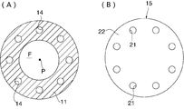
- (A) is a schematic sectional view of the free piston engine in the direction along the line AA of FIG. 1, and (B) is a front view conceptually showing a rotary valve.
- (A), (B), (C) is a schematic sectional drawing for demonstrating operation
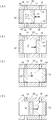
- (A) is the schematic sectional drawing which showed notionally the structure of the free piston engine which concerns on 2nd Embodiment, (B), (C), (D) is from the state of (A) to an exhaust stroke. It is a schematic sectional drawing for demonstrating operation
- (A), (B), (C), (D) is a schematic sectional view for explaining the operation of the free piston engine from the state of FIG. 4 (D) to the intake stroke. It is a graph for demonstrating the operation
- (A) is the schematic sectional drawing which showed notionally the structure of the free piston engine which concerns on 3rd Embodiment, (B), (C), (D) is the free piston from the state of (A). It is a schematic sectional drawing for demonstrating operation
- FIG. 1 is a schematic sectional view conceptually showing the structure of the free piston engine according to the first embodiment.
- a free piston engine 10 is housed in a cylindrical cylinder 11 and an internal space of the cylinder 11, and is provided with a piston that is movable in a direction along the central axis of the internal space (the left-right direction in FIG. 1).
- 12 and the intake port 14 for introducing outside air into the cylinder 11, which is formed on the left end side of the cylinder 11, and adjacent to the left side of the cylinder 11 in FIG.
- a rotary valve 15 for controlling the inflow of the cylinder 11 and an exhaust port 16 for discharging exhaust gas generated in the cylinder 11 to the outside of the engine.
- the piston 12 is formed in a columnar shape or a disk shape having an outer diameter substantially the same as or slightly smaller than the inner diameter of the cylinder 11, and an end surface (left end surface in FIG. 1) located on the intake port 14 side and the cylinder 11.
- a space surrounded by the inner wall portion constitutes a combustion space F in which a mixture of outside air and fuel introduced from the intake port 14 burns.
- the piston 12 can reciprocate between the most compressed position that minimizes the volume of the combustion space F and the most expanded position that maximizes the volume.
- the piston 12 moves in the expansion direction (rightward in FIG. 1) that increases the volume of the combustion space F from the most compressed position, the explosive force due to the combustion of the air-fuel mixture in the combustion space F drives the piston 12.
- the power extraction mechanism is not particularly limited, and is a mechanism for rotating a motor of a generator such as a linear generator using an electromagnetic effect provided in the free piston engine 10 or for rotating an axle of an automobile.
- Various known mechanisms such as a mechanical structure such as a crank can be applied.
- the piston drive device (not shown) is omitted. The driving force is used.
- a motor or the like can be exemplified, but various piston structures can be adopted as long as the piston 12 can be operated in the compression direction.
- the cylinder 11 is provided with injection means for injecting fuel into the combustion space F, and combusts a mixture of fuel from the injection means and outside air introduced from the intake port 14. It is generated in the space F.
- the injection means may be provided in the middle of the intake port 14 and the air-fuel mixture may be supplied from the intake port 14 to the combustion space F.
- the intake port 14 is a flow path that extends from an intake port 18 that opens to the left end surface of the cylinder 11 in FIG. 1 to a jet port 19 that opens to the combustion space F.
- a jet port 19 that opens to the combustion space F.
- FIG. 11 are formed at a plurality of positions (eight positions in the present embodiment) at equal intervals along the circumferential direction.
- Each jet 19 has the same shape as each other, and is always provided at a position where it opens into the cylinder 11 regardless of the movement of the piston 12.
- each jet 19 forms a jet by jetting outside air from a position that is substantially equidistant in the circumferential direction of the inner peripheral wall of the cylinder 11 toward a certain region of the combustion space F, that is, the collision center P in the center of the inside.
- the air-fuel mixture is compressed by colliding the jet of the outside air ejected from each ejection port 19.
- the flow path of the intake port 14 in the vicinity of the jet port 19 is preferably provided with a linearly extending portion, that is, a straight pipe portion so as not to make the jet direction of the jet flow due to the Counder effect unstable.
- the rotary valve 15 has a disk shape and is supported by the cylinder 11 so as to be rotatable about the central axis of the combustion space F.
- the rotary valve 15 can be rotated forward and backward at a predetermined timing by driving a rotating device (not shown). Yes. That is, the rotary valve 15 is opened to allow the outside air to be taken into the combustion space F from the intake port 14 by the rotating operation, and closed to restrict the take-in of the outside air from the intake port 14 to the combustion space F. Can be switched between.
- the rotary valve 15 includes round holes 21 formed at equal intervals in the circumferential direction at a plurality of positions (eight positions in the present embodiment) near the outer edge, and the holes.
- Each hole 21 is formed at a position and a size that can communicate with each other relative to each suction port 18 of the intake port 14.
- the surface portion 22 is formed so as to block all the suction ports 18 when facing the suction ports 18 by the rotation of the rotary valve 15. In this embodiment, when the rotary valve 15 is in the closed position, the suction port 18 is completely closed with respect to the external space, but the suction port 18 is slightly opened with respect to the external space. You may be in the state to do.
- the exhaust ports 16 are formed at a plurality of positions (eight locations in the present embodiment) that are equally spaced along the circumferential direction of the cylinder 11, and each exhaust port 16 is positioned at the right side in FIG. 11 is provided with an exhaust port 24 opened.
- the exhaust port 24 opens to the combustion space F when the piston 12 reaches the maximum expansion position indicated by the broken line in the figure. At that time, the exhaust gas generated in the combustion space F is The exhaust port 16 can discharge to the outside of the free piston engine 10.
- the piston 12 prevents the gas from flowing between the combustion space F and the exhaust port 24. Therefore, the piston 12 also functions as a valve for the exhaust port 16.
- the rotary valve 15 is set to the open position, and outside air is introduced from the outside of the free piston engine 10 into the intake port 14, and the outside air is supplied to the combustion space F.
- the outside air supplied to the combustion space F is jetted radially from the respective jet outlets 19 toward the collision part P as a jet, and is collided and compressed in the collision part P while being mixed with fuel.
- a collision jet flow is generated around the collision portion P.
- the piston 12 moves in the compression direction (left side in the figure), the volume of the combustion space F is reduced, and the air-fuel mixture is further compressed. become.
- the piston 12 exists between the jet port 19 of the intake port 14 and the exhaust port 24 of the exhaust port 16, and the piston 12 causes a gap between the combustion space F and the exhaust port 24. The gas flow is cut off.
- the piston 12 moves in the expansion direction (in the figure).
- the power is extracted by a power extraction mechanism (not shown).
- the method for burning and exploding the air-fuel mixture is not particularly limited.
- the ignition means (not shown) exemplified by laser ignition or the like, the ignition means. It is also possible to adopt a self-ignition method that can burn and explode at the time of compression depending on the characteristics of the fuel, without using.
- the piston 12 moves in the compression direction (left side in the figure) by driving the piston driving device (not shown) while the rotary valve 15 is in the closed position.
- the gas in the combustion space F is compressed in a state where the outflow of gas from the combustion space F to the exhaust port 24 is blocked.
- the rotary valve 15 is opened again, and the negative pressure already generated in the combustion space F is utilized. Outside air is introduced into the combustion space F, and the above operation is repeated with the above as one cycle.
- the operation timing of the piston 12 by the piston driving device (not shown) and the opening / closing timing of the rotary valve 15 by driving the rotating device (not shown) are shown in the figure, such as the position of the piston 12 and the pressure state of the combustion space F. Control is performed by a control device (not shown) based on the measurement results of various sensors that are not.
- the opening / closing operation for switching between the open position and the closed position of the rotary valve 15 is repeatedly performed, and the outside air intermittently flows from each jet port 19 toward the collision portion P as a jet flow.
- multiple gas collisions are intermittently generated at the collision part P, and a pulsed collision jet is generated in the combustion space F.
- the pressure of the combustion space F can be temporarily reduced to bring the combustion space F into a negative pressure state, and the rotary valve 15 is moved from the closed position to the open position.
- the intake of outside air from each jet port 19 is promoted, and the intake efficiency into the combustion space F can be increased.
- the compression of the air-fuel mixture in the combustion space F is performed by both the collision jet flow and the movement of the piston 12, a high compression effect can be obtained and the stroke of the piston 12 can be shortened.
- the piston 12 can be reciprocated at a high frequency.
- a valve mechanism such as a reciprocating engine is not required, the compression ratio, expansion ratio, intake / exhaust timing, and engine speed can be made infinitely variable.
- the high-speed airflow generated around the collision part P can be confined without diffusing the noise in the combustion space F, and the noise is reduced as compared with the conventional engine. be able to.
- harmful substances in the exhaust gas can be burned efficiently, the residual amount of the harmful substances can be reduced, and the exhaust gas can be cleaned.
- the free piston engine 10 of the present embodiment has a structure compatible with the compression method of the air-fuel mixture by the collision jet, and can achieve higher efficiency and higher output than the conventional engine. In addition to being able to respond to a wide range of output demands, it is possible to reduce engine noise and contribute to cleaner exhaust gas.
- the formation edge of the suction port 18 and the hole portion 21 is made a smooth non-arc-shaped curve, so that the rotary valve 15 is positioned between the open position and the closed position. Noise due to separation of outside air at the time of switching can be greatly suppressed. Further, by increasing the thickness of the surface portion 22 located around the hole portion 21 as the distance from the hole portion 21 of the rotary valve 15 increases, noise can be similarly suppressed.
- FIG. 4A is a schematic cross-sectional view conceptually showing the structure of the free piston engine 30 according to the second embodiment.
- the free piston engine 30 according to the present embodiment is characterized in that a piston type valve 32 is provided in the cylinder 11 instead of the rotary valve 15 with respect to the free piston engine 10 of the first embodiment.
- a piston type valve 32 is provided in the cylinder 11 instead of the rotary valve 15 with respect to the free piston engine 10 of the first embodiment.
- the piston-type valve 32 is formed in a columnar shape or a disk shape having an outer diameter substantially the same as or slightly smaller than the inner diameter of the cylinder 11, and is disposed relative to the left side of the piston 12 in FIG.
- the combustion space F in the present embodiment is formed in a space surrounded between the piston 12 and the piston type valve 32 in the cylinder 11.
- the piston-type valve 32 can be moved in the same direction as the operation direction of the piston 12, that is, in the left-right direction in the figure, by a valve driving device constituted by a motor (not shown).
- the power extraction mechanism may be connected to the piston type valve 32 so that work can be extracted by the operation of the piston type valve 32.
- the piston type valve 32 is fixed to the initial position at the left end in the figure so as not to move, and the piston 12 introduces outside air into the combustion space F from the ejection port 19. Arranged as possible.
- the external air in the jet state supplied to the combustion space F collides with the collision portion P while being mixed with fuel, and the air-fuel mixture is compressed while generating the collision jet, as in the first embodiment.
- the piston 12 is moved in the compression direction (left side in the figure) by the driving of the piston driving device (not shown), and the air-fuel mixture in the combustion space F is further compressed.
- the piston 12 exists between the jet port 19 and the exhaust port 24, and the gas flow between the combustion space F and the exhaust port 24 is blocked by the piston 12.
- the piston type valve 32 exists between the jet port 19 and the exhaust port 24, and the piston type valve 32 causes the combustion space F from the jet port 19 to exist. The introduction of outside air to is blocked. Then, as shown in FIG. 5A, the piston type valve 32 moves so as to be substantially in contact with the piston 12 at a position in the vicinity of the exhaust port 24, and the volume of the combustion space F is made substantially zero. The exhaust gas in the combustion space F is forcibly discharged from the exhaust port 24 to the exhaust port 16. The piston-type valve 32 does not have to move to the position in the figure, that is, the position where the exhaust port 24 is almost completely closed.
- the piston 12 and the piston-type valve 32 increase the distance between the piston 12 and the valve drive device by driving the piston drive device and the valve drive device (not shown). Move to the left in the figure).
- FIG. 5C when the piston 12 and the piston-type valve 32 move to a position where the gas flow between the ejection port 19 and the exhaust port 24 and the combustion space F is blocked, the combustion occurs. The space F is closed. In this state, when the piston 12 and the piston-type valve 32 move together in the direction of the jet port 19 (leftward in the figure) while increasing the mutual separation distance, the volume of the closed combustion space F expands, and the combustion space A negative pressure is generated in F. Then, as shown in FIG.
- the piston 12 and the piston-type valve 32 operate asymmetrically so that a negative pressure can be generated in the combustion space F after exhausting, but their operation timing depends on the position of the piston 12, the pressure state of the combustion space F, etc. Control is performed by a control device (not shown) based on the measurement results of various sensors (not shown).
- the rotary valve 15 since the rotary valve 15 is not required for the first embodiment, the operation sound associated with the opening / closing operation of the rotary valve 15 does not occur, and the entire configuration is eliminated. Noise suppression effect can be further enhanced. Further, the rotary mechanism of the rotary valve 15 is not required, so that the entire engine can be further reduced in size and weight, and the durability of the engine can be improved.
- the movement of the piston type valve 32 facilitates the exhaust of the exhaust gas to the exhaust port 16 so that the exhaust can be performed more efficiently, and the higher efficiency and higher output of the engine can be further promoted. .
- a collision jet is not generated in the combustion space F, but the outside air is simply introduced into the combustion space F from the ejection port 19 and the fuel / air mixture is combusted and exploded. It is good also as a type to be made.
- the jet outlet 19 and the exhaust outlet 24 opened in the cylinder 11 can be provided at only one place.
- control device when the piston 12 and the piston type valve 32 move after the exhaust gas is discharged, the distance between them can be adjusted so that a desired negative pressure can be obtained. For example, it is possible to control the operations of the piston drive device and the valve drive device so that the negative pressure is zero immediately after the engine is started and the negative pressure gradually increases.
- the piston 12 and the piston-type valve 32 are mechanically configured so that the piston 12 operates in an integer number of cycles (for example, three is preferable, see FIG. 6) while the piston-type valve 32 operates in one cycle. can do.
- the movement of the piston 12 and the piston type valve 13 and the extraction of power are operations close to a simple sine wave using only a mechanical structure such as a crank, and performance equivalent to or higher than that of the present embodiment is realized. Is possible.
- the operation may be performed by the control by the control device. According to this, the movement range of the piston 12 is reduced, and the stroke of the piston 12 can be reduced. In FIG.
- the upper curve represents the piston position during one cycle in the piston 12
- the lower curve represents the piston position during one cycle in the piston-type valve 32.
- the piston position corresponds to the position of the left end in the cylinder 11 in the figure
- the upper end in the figure corresponds to the position of the right end in the cylinder 11.
- the same number of exhaust ports 24 as the ejection ports 19 are provided, and the respective exhaust ports 24 are arranged corresponding to the respective ejection ports 19 in the axial direction of the combustion space F, that is, for each ejection port 19 and each exhaust port 24.
- a part of the exhaust gas discharged from the exhaust port 24 is provided by matching the circumferential position of the combustion space F and providing an EGR port that communicates with each of the intake ports 14 and the exhaust ports 16. May be ejected from the corresponding ejection port 19 together with outside air. According to this configuration, compression and combustion in the combustion space F can be performed more stably.
- the jet flow from each jet 19 becomes strong and weak, and the jet stream after the jet collision in the direction of the jet 19 having a weak jet is generated.
- the amount of exhaust gas to the exhaust port 24 at the circumferential position corresponding to the jet port 19 increases, and therefore the amount of jet flow from the jet port 19 increases in the next cycle. It functions to guide the misaligned jet stream to the normal position.
- the combustion state of the combustion space F including the amount of jet flow from each jet port 19 is detected by a sensor or the like, and the jet amount of exhaust gas from each jet port 19 is electromagnetically controlled based on these detection values.
- Means can also be provided. Examples of the means include a solenoid valve provided in the EGR port and a control device for controlling the solenoid valve.
- each jet port 19 can be provided in such a direction that the collision part P is formed closer to the exhaust port 16 so that the jet flow can be supplied to the combustion space F, thereby shortening the stroke of the piston type valve 32. be able to.
- FIG. 7A is a schematic cross-sectional view conceptually showing the structure of the free piston engine according to the third embodiment.
- the free piston engine 40 according to the present embodiment is different from the first embodiment in that the piston 12 and the exhaust port 16 are arranged in the direction along the central axis of the combustion space F without providing the rotary valve 15.
- a pair is provided and is characterized in that it is arranged symmetrically in the drawing with the intake port 14 as the center.
- the pair of pistons 12 and 12 can operate symmetrically in FIG. 7A.
- the intake ports 14 are not particularly limited, but a plurality of sets are formed in the circumferential direction of the cylinders 11 as three rows and one set around the cylinders 11, and the intake ports 14 existing in the center are formed. As the center, the other two intake ports 14 and 14 are formed to be symmetrical in the figure.
- each of the ejection ports 19 of the three rows of intake ports 14 is provided so as to be able to eject outside air radially toward the collision part P, as in the above-described embodiments.
- the air-fuel mixture collides more than in the above embodiments, and a collision jet is generated to compress the air-fuel mixture.
- the exhaust ports 16 are arranged symmetrically on the left and right ends in the figure.
- the left and right pistons 12 and 12 in the figure are arranged with a certain gap so as to form a combustion space F therebetween, and each intake air All the ejection ports 19 of the working port 14 are arranged so as to open to the combustion space F.
- outside air is introduced into each intake port 14, and the outside air is supplied to the combustion space F through each ejection port 19.
- the outside air supplied to the combustion space F is ejected radially toward the collision part P while being mixed with the fuel, thereby generating multiple collision jets and compressing the mixture.
- each piston 12, 12 exists between the jet outlet 19 and the exhaust port 24, and the piston 12, 12 causes the combustion space F and each exhaust port 24, 24 to be in contact with each other. The gas flow between them will be blocked.
- the pistons 12 and 12 move in directions approaching each other as shown in FIG.
- the pistons 12 and 12 are positioned between the combustion space F and the exhaust port 24, and the gas flow between the combustion space F and the exhaust port 24 is blocked by the presence of the pistons 12 and 12. .
- outside air is introduced into the combustion space F from the respective outlets 19, and the pistons 12, 12 approach each other.
- the air-fuel mixture in the combustion space F is compressed, and the above operation is repeated with the above as one cycle.
- the operation timing of the pistons 12 and 12 by a piston drive device is controlled by a control device (not shown) as in the above embodiments.
- the intake port 18 of the intake port 14 may be formed so as to open to a surface portion of a moving body (not shown) on which the free piston engine 10 is mounted.
- a part of the air passing through the surface portion is introduced from the suction port 18 to the intake port 14, and the air flow along the surface portion is in the middle of the surface portion. Since the transition from laminar flow to turbulent flow is suppressed, air resistance caused by the transition can be greatly reduced.
- the particle size of the catalyst is preferably 10 nm or less.
- the local mixing ratio is fuel richer than the theoretical mixing ratio so that hydrogen is generated after combustion.
- the catalyst may be applied and formed in a thin film on the center of the surface of the piston 12 on the combustion space F side without being mixed into the fuel.
- each of the ejection ports 19 is preferably arranged symmetrically with respect to the central axis of the combustion space F, and is provided at three or more locations in the circumferential direction of the cylinder 11.
- the rate of change over time of the jet flow rate from the jet port 19 can be varied when the opening area of the jet port 19 is increased or decreased over time. This can reduce noise and vibration.
- the piston 12 is moved from the most compressed position toward the most expanded position, and / or the piston type valve 32 is moved from the initial position toward the exhaust port 16. It is good to let them. Thereby, work is taken out to the maximum and the thermal efficiency can be optimized.
- a first mode in which combustion is performed only by compression of the piston 12 without generating a collision jet in the combustion space F, and a second mode in which combustion is performed by generating the collision jet in the combustion space F. Can be controlled to be switchable.
- the first mode uniform compression is performed in the combustion space F as in mechanical compression using a conventional reciprocating engine, while in the second mode, as described above, the internal center of the combustion space F is obtained.
- the compression is mainly performed in the vicinity of the collision part P.
- exhaust gas can be introduced together with the gas from the jet outlet 19 so that the exhaust gas can collide with the collision jet.
- the compression ratio can be increased, detonation can be suppressed by increasing the air-fuel ratio, and unnecessary vibration of the piston 12 can be suppressed.
- the introduction of the exhaust gas into the combustion space F is performed by connecting the exhaust port 16 to the intake port 14, and the operation of the piston 12 is controlled by the control device, and the injection port 19.
- the exhaust gas can be introduced together with the gas from the ejection port 19, such as a configuration in which the exhaust gas is introduced from the exhaust port 24 when the gas is introduced from the exhaust port 24, various configurations can be adopted.
- a plasma flow by repeatedly colliding a plurality of jets at the collision part P and generating a pulsed collision jet.
- Power generation by the electromagnetic effect using the flow is also possible.
- a magnet is arranged in the vicinity of the collision part P, and power is generated by an MHD (Magneto Hydrodynamics) effect by a plasma flow.
- MHD Magnetic Hydrodynamics
- the power generation is possible even when the piston 12 or the piston type valve 32 is not operating or when the piston valve 32 is operating slowly, a part of the airflow energy in the combustion space F can be used for power generation, the airflow velocity is reduced, Efficient energy generation is possible.
- the power generation can be used as a power source such as the above-described piston drive device, valve drive device, and supercharger.
- each part of the apparatus according to the present invention is not limited to the illustrated configuration example, and various modifications are possible as long as substantially the same operation is achieved.
- the intake port 14 and the exhaust port 16 may be smoothly curved.
- the present invention is suitable not only as a power source for generators and automobiles but also as a source of thrust for aircraft, rockets, etc., and can also be used as power for a wide range of devices.
Landscapes
- Engineering & Computer Science (AREA)
- Mechanical Engineering (AREA)
- General Engineering & Computer Science (AREA)
- Chemical & Material Sciences (AREA)
- Combustion & Propulsion (AREA)
- Combustion Methods Of Internal-Combustion Engines (AREA)
Abstract
Description
図1には、第1実施形態に係るフリーピストンエンジンの構造を概念的に示した概略断面図が示されている。この図において、フリーピストンエンジン10は、円筒状のシリンダ11と、シリンダ11の内部空間に収容され、当該内部空間の中心軸に沿う方向(図1中左右方向)に移動可能に設けられたピストン12と、シリンダ11の同図中左端側に形成され、シリンダ11内に外気を導入するための吸気用ポート14と、シリンダ11の同図中左方に隣接し、吸気用ポート14への外気の流入をコントロールするロータリーバルブ15と、シリンダ11の同図中右端寄りの部分に形成され、シリンダ11内に発生した排気ガスをエンジン外部に排出するための排気用ポート16とを備えている。
図4(A)には、第2実施形態に係るフリーピストンエンジン30の構造を概念的に示した概略断面図が示されている。この図において、本実施形態に係るフリーピストンエンジン30は、前記第1実施形態のフリーピストンエンジン10に対し、ロータリーバルブ15の代わりに、シリンダ11内にピストン型バルブ32を設けたところに特徴を有する。
図7(A)には、第3実施形態に係るフリーピストンエンジンの構造を概念的に示した概略断面図が示されている。この図において、本実施形態に係るフリーピストンエンジン40は、前記第1実施形態に対し、ロータリーバルブ15を設けずに、ピストン12及び排気用ポート16を燃焼空間Fの中心軸に沿う方向にそれぞれ一対設け、吸気用ポート14を中心に同図中左右対称にそれぞれ配置したところに特徴を有する。
12 ピストン
14 吸気用ポート
15 ロータリーバルブ
16 排気用ポート
18 吸入口
19 噴出口
21 穴部
22 面部
24 排気口
30 フリーピストンエンジン
32 ピストン型バルブ
40 フリーピストンエンジン
F 燃焼空間
P 衝突部
Claims (19)
- 外気と燃料の混合気を燃焼させる燃焼空間と、当該燃焼空間の容積を最小にする最圧縮位置と当該容積を最大にする最膨張位置との間で往復運動可能に設けられたピストンと、当該ピストンを動作させるピストン駆動装置と、前記燃焼空間に前記外気若しくは前記混合気からなる気体を導入する吸気用ポートと、前記燃焼空間で発生した排気ガスを外部に導く排気用ポートと、前記燃焼空間の中心軸方向に沿って移動することで、前記吸気用ポートを開閉可能にするピストン型バルブと、当該ピストン型バルブを動作させるバルブ駆動装置とを備え、
前記ピストンは、前記燃焼空間での前記混合気の燃焼による爆発力により、前記最圧縮位置から前記最膨張位置に移動して動力を取り出す一方、前記ピストン駆動装置の作動により、前記最膨張位置から前記最圧縮位置に戻るように設けられるとともに、前記排気用ポートのバルブとして機能し、前記最膨張位置に達したときに、前記燃焼空間に対して前記排気用ポートを開放する一方、それ以外の位置に存在するときに、前記燃焼空間に対して前記排気用ポートを閉塞するように配置され、
前記ピストン型バルブは、前記ピストンに相対配置され、当該ピストンとの間に囲まれる空間に前記燃焼空間を形成し、前記バルブ駆動装置の作動により、前記燃焼空間での燃焼後に、前記吸気用ポートが前記燃焼空間に開放する初期位置から、前記排気用ポートへの前記排気ガスの排出を促進する方向に移動し、前記排気ガスの排出が終了した後に前記初期位置に戻ることを特徴とするフリーピストンエンジン。 - 前記ピストン駆動装置及び前記バルブ駆動装置は、前記ピストンと前記ピストン型バルブを、 非対称に動作可能に設けられるとともに、前記排気ガスの排出が終了した後に、前記ピストン及び前記ピストン型バルブで前記燃焼空間を閉塞した状態で、前記ピストンと前記ピストン型バルブとの離間距離を拡げながら、前記気体の導入前の前記燃焼空間に負圧を発生可能に設けられることを特徴とする請求項1記載のフリーピストンエンジン。
- 前記吸気用ポートは、前記気体を前記燃焼空間の内部中央に位置する一定領域に向かってそれぞれ噴出可能に形成された複数の噴出口を備え、
前記燃焼空間では、前記ピストンの移動による前記混合気の圧縮に加え、前記各噴出口からそれぞれ噴出された噴流状態の前記気体を前記一定領域で衝突させることで、衝突噴流を発生させながら前記混合気を圧縮させることを特徴とする請求項1又は2記載のフリーピストンエンジン。 - 前記各噴出口は、前記燃焼空間の中心軸に対して軸対称に配置され、
前記排気用ポートは、前記燃焼空間に開放する排気口を備え、当該排気口は、少なくとも前記噴出口と同数設けられるとともに、当該各噴出口に対しそれぞれ前記燃焼空間の軸線方向に対応して配置され、前記排気口から排出された排気ガスの一部が、対応する前記各噴出口から前記気体とともに噴出可能に設けられていることを特徴とする請求項3記載のフリーピストンエンジン。 - 前記排気用ポートは、前記燃焼空間に開放する排気口を備え、当該排気口から排出された排気ガスの一部が、前記各噴出口から前記気体とともに噴出可能に設けられ、
前記燃焼空間の燃焼状態に応じて前記各噴出口からの前記排気ガスの噴出量を制御する手段を備えたことを特徴とする請求項3記載のフリーピストンエンジン。 - 前記燃焼空間での燃焼直前に、前記ピストンを前記最圧縮位置から前記最膨張位置に向かう方向に移動させ、及び/又は、前記ピストン型バルブを前記初期位置から前記排気用ポートへの前記排気ガスの排出を促進する方向に移動させることを特徴とする請求項1、2又は3記載のフリーピストンエンジン。
- 前記ピストン駆動装置及び前記バルブ駆動装置の作動と、前記燃焼空間に導入される前記気体の状態とを制御する制御装置を備え、
前記制御装置では、前記燃焼空間に前記衝突噴流を発生させずに、前記ピストンの圧縮のみによる燃焼を行う第1モードと、前記燃焼空間に前記衝突噴流を発生させて燃焼を行う第2モードとを切り換え可能に前記制御を行うことを特徴とする請求項3記載のフリーピストンエンジン。 - 前記ピストン駆動装置及び前記バルブ駆動装置の作動を制御する制御装置を備え、
前記制御装置では、前記ピストンと前記ピストン型バルブの離間距離を調整することで、前記負圧がエンジン始動時から次第に増大するように、前記ピストン駆動装置及び前記バルブ駆動装置の作動を制御することを特徴とする請求項2又は3記載のフリーピストンエンジン。 - 前記燃焼空間は、前記気体の導入とともに、前記排気用ポートから前記排気ガスを導入し、当該排気ガスを前記衝突噴流に衝突可能に設けられることを特徴とする請求項3記載のフリーピストンエンジン。
- 前記噴出口は、その形成縁が非円形の曲線状をなす形状に設けられていることを特徴とする請求項3記載のフリーピストンエンジン。
- 前記ピストン及び前記ピストン型バルブは、前記ピストン型バルブが前記初期位置から当該初期位置に戻るサイクルを1回行う間に、前記ピストンが前記最圧縮位置から前記最圧縮位置に戻るサイクルを整数回行い、若しくは、前記ピストンの前記サイクルを1回行う間に、前記ピストン型バルブの前記サイクルを整数回行うように構成されることを特徴とする請求項3記載のフリーピストンエンジン。
- 前記燃料を含まない外気のみが前記燃焼空間に導入されて燃焼を行わない停止サイクルを生成する手段を備えたことを特徴とする請求項3記載のフリーピストンエンジン。
- 前記各噴出口は、前記一定領域が前記排気ポート寄りに形成される向きで、前記噴流を前記燃焼空間に供給可能に設けられていることを特徴とする請求項3記載のフリーピストンエンジン。
- 外気と燃料の混合気を燃焼させる燃焼空間と、当該燃焼空間の容積を最小にする最圧縮位置と当該容積を最大にする最膨張位置との間で往復運動可能に設けられたピストンと、当該ピストンを動作させるピストン駆動装置と、前記燃焼空間に前記外気若しくは前記混合気からなる気体を導入する吸気用ポートと、前記燃焼空間で発生した排気ガスを外部に導く排気用ポートとを備えたフリーピストンエンジンにおいて、
前記ピストンは、前記燃焼空間での前記混合気の燃焼による爆発力により、前記最圧縮位置から前記最膨張位置に移動して動力を取り出す一方、前記ピストン駆動装置の作動により、前記最膨張位置から前記最圧縮位置に戻るように設けられるとともに、前記排気用ポートのバルブとして機能し、前記最膨張位置に達したときに、前記燃焼空間に対して前記排気用ポートを開放する一方、それ以外の位置に存在するときに、前記燃焼空間に対して前記排気用ポートを閉塞し、
前記吸気用ポートは、前記気体を前記燃焼空間の内部中央に位置する一定領域に向かってそれぞれ噴出可能に形成された複数の噴出口を備え、
前記燃焼空間では、前記ピストンの移動による前記混合気の圧縮に加え、前記各噴出口からそれぞれ噴出された前記気体を前記一定領域で衝突させることで、衝突噴流を発生させながら前記混合気を圧縮させることを特徴とするフリーピストンエンジン。 - 前記吸気用ポートから前記燃焼空間への前記気体の取り込みを許容する開位置と、前記吸気用ポートから前記燃焼空間への前記気体の取り込みを阻止する閉位置との間で切替可能なロータリーバルブを更に備え、
前記ロータリーバルブは、前記開位置のときに前記吸気用ポートに連なって通ずる穴部と、当該穴部の周囲に位置し、前記閉位置のときに前記吸気用ポートに相対する面部とを備え、前記燃焼空間の中心軸回りに回転することで、前記吸気用ポートの開閉を切り替えることを特徴とする請求項14記載のフリーピストンエンジン。 - 前記ロータリーバルブは、前記穴部の形成縁が非円弧状の曲線に形成され、及び/又は、外周側の領域の肉厚が中心に向かって次第に増大するように形成され、前記穴部を通過する際の気体剥離を抑制可能に設けられていることを特徴とする請求項15記載のフリーピストンエンジン。
- 前記ピストン及び前記排気用ポートは、前記燃焼空間の中心軸に沿う方向に一対設けられるとともに、前記吸気用ポートを中心に相互に対称となるように配置され、前記燃焼空間は、前記各ピストンの間に形成され、前記ピストンは、相互に離間接近するように移動することを特徴とする請求項14記載のフリーピストンエンジン。
- 前記吸気用ポートは、前記外気を外部から取り込む吸入口を含み、当該吸入口は、フリーピストンエンジンが搭載される移動体の表面部分に開放することで、当該移動体の移動時に、前記表面部分に沿う空気流の層流から乱流への遷移を抑制可能に形成されていることを特徴とする請求項1、2又は14記載のフリーピストンエンジン。
- 前記吸気用ポートの上流側には、前記吸気用ポートに導入される前記気体の圧力を上げ、前記燃焼空間の圧力が大気圧以上の状態のときにおいても、前記気体を噴流状態で前記燃焼空間に導入可能にする過給機を設けたことを特徴とする請求項3記載のフリーピストンエンジン。
Priority Applications (2)
| Application Number | Priority Date | Filing Date | Title |
|---|---|---|---|
| JP2013528045A JP5971598B2 (ja) | 2011-08-09 | 2012-08-08 | フリーピストンエンジン |
| US14/235,713 US9388736B2 (en) | 2011-08-09 | 2012-08-08 | Free-piston engine |
Applications Claiming Priority (2)
| Application Number | Priority Date | Filing Date | Title |
|---|---|---|---|
| JP2011-173625 | 2011-08-09 | ||
| JP2011173625 | 2011-08-09 |
Publications (1)
| Publication Number | Publication Date |
|---|---|
| WO2013022019A1 true WO2013022019A1 (ja) | 2013-02-14 |
Family
ID=47668525
Family Applications (1)
| Application Number | Title | Priority Date | Filing Date |
|---|---|---|---|
| PCT/JP2012/070175 Ceased WO2013022019A1 (ja) | 2011-08-09 | 2012-08-08 | フリーピストンエンジン |
Country Status (3)
| Country | Link |
|---|---|
| US (1) | US9388736B2 (ja) |
| JP (1) | JP5971598B2 (ja) |
| WO (1) | WO2013022019A1 (ja) |
Cited By (1)
| Publication number | Priority date | Publication date | Assignee | Title |
|---|---|---|---|---|
| JP2017008802A (ja) * | 2015-06-22 | 2017-01-12 | 学校法人早稲田大学 | クランクレスエンジン |
Citations (3)
| Publication number | Priority date | Publication date | Assignee | Title |
|---|---|---|---|---|
| JP2003519328A (ja) * | 1999-12-30 | 2003-06-17 | ハネウェル・インコーポレーテッド | マイクロ燃焼エンジン/発電機 |
| JP2008522101A (ja) * | 2004-12-02 | 2008-06-26 | サーコス・インヴェストメンツ・エルシー | 動的質量移送迅速応答動力変換システム |
| JP2008223657A (ja) * | 2007-03-14 | 2008-09-25 | Mazda Motor Corp | フリーピストンエンジン |
Family Cites Families (8)
| Publication number | Priority date | Publication date | Assignee | Title |
|---|---|---|---|---|
| US4066720A (en) * | 1973-08-30 | 1978-01-03 | Carter Efton T | Carburetor air intake velocity stack |
| US5775273A (en) * | 1997-07-01 | 1998-07-07 | Sunpower, Inc. | Free piston internal combustion engine |
| US6035637A (en) * | 1997-07-01 | 2000-03-14 | Sunpower, Inc. | Free-piston internal combustion engine |
| US6349682B1 (en) * | 2000-02-09 | 2002-02-26 | Richard C. Alexius | Free piston engine and self-actuated fuel injector therefor |
| US6691664B2 (en) * | 2001-04-12 | 2004-02-17 | Joseph Samuel Pisano | Direct port rotary valve mechanism with variable timing for internal combustion engines |
| US6957632B1 (en) * | 2004-05-20 | 2005-10-25 | Ford Global Technologies, Llc | Air charging system for an opposed piston opposed cylinder free piston engine |
| JP2007107475A (ja) | 2005-10-14 | 2007-04-26 | Denso Corp | 2サイクルエンジン |
| DE102007035914A1 (de) * | 2007-07-23 | 2009-01-29 | Umc Universal Motor Corporation Gmbh | Freikolbenvorrichtung und Verfahren zur Steuerung und/oder Regelung einer Freikolbenvorrichtung |
-
2012
- 2012-08-08 WO PCT/JP2012/070175 patent/WO2013022019A1/ja not_active Ceased
- 2012-08-08 US US14/235,713 patent/US9388736B2/en active Active
- 2012-08-08 JP JP2013528045A patent/JP5971598B2/ja active Active
Patent Citations (3)
| Publication number | Priority date | Publication date | Assignee | Title |
|---|---|---|---|---|
| JP2003519328A (ja) * | 1999-12-30 | 2003-06-17 | ハネウェル・インコーポレーテッド | マイクロ燃焼エンジン/発電機 |
| JP2008522101A (ja) * | 2004-12-02 | 2008-06-26 | サーコス・インヴェストメンツ・エルシー | 動的質量移送迅速応答動力変換システム |
| JP2008223657A (ja) * | 2007-03-14 | 2008-09-25 | Mazda Motor Corp | フリーピストンエンジン |
Cited By (1)
| Publication number | Priority date | Publication date | Assignee | Title |
|---|---|---|---|---|
| JP2017008802A (ja) * | 2015-06-22 | 2017-01-12 | 学校法人早稲田大学 | クランクレスエンジン |
Also Published As
| Publication number | Publication date |
|---|---|
| JP5971598B2 (ja) | 2016-08-17 |
| US9388736B2 (en) | 2016-07-12 |
| US20140283791A1 (en) | 2014-09-25 |
| JPWO2013022019A1 (ja) | 2015-03-05 |
Similar Documents
| Publication | Publication Date | Title |
|---|---|---|
| JP5737632B2 (ja) | エンジン | |
| US10208598B2 (en) | Rotary energy converter with retractable barrier | |
| JP6132979B2 (ja) | 燃焼ガスを駆動力として噴出するエンジン | |
| JP6246988B2 (ja) | エンジン | |
| US20040128974A1 (en) | High efficiency low hydrocarbon emmisson hybrid power plant using operational aspects of both internal combustion and jet engines | |
| CN105164374B (zh) | 旋转式内燃机 | |
| US8061327B2 (en) | Tangential combustion turbine | |
| CN109196200B (zh) | 自由活塞装置和自由活塞装置的操作方法 | |
| JP5971598B2 (ja) | フリーピストンエンジン | |
| JP2020045903A (ja) | エンジン | |
| JP2022520878A (ja) | 回転式内燃機関 | |
| JP2025086401A (ja) | 多重衝突パルス噴流圧縮方式のエンジン | |
| RU80896U1 (ru) | Роторно-лопастной двигатель низамова | |
| JP7291315B2 (ja) | エンジン | |
| JP6601866B2 (ja) | クランクレスエンジン | |
| CN120798528A (zh) | 一种电磁驱动的航空发动机快速模态切换装置及方法 |
Legal Events
| Date | Code | Title | Description |
|---|---|---|---|
| 121 | Ep: the epo has been informed by wipo that ep was designated in this application |
Ref document number: 12822261 Country of ref document: EP Kind code of ref document: A1 |
|
| ENP | Entry into the national phase |
Ref document number: 2013528045 Country of ref document: JP Kind code of ref document: A |
|
| NENP | Non-entry into the national phase |
Ref country code: DE |
|
| WWE | Wipo information: entry into national phase |
Ref document number: 14235713 Country of ref document: US |
|
| 122 | Ep: pct application non-entry in european phase |
Ref document number: 12822261 Country of ref document: EP Kind code of ref document: A1 |