WO2013021870A1 - 冷却装置及びその製造方法 - Google Patents
冷却装置及びその製造方法 Download PDFInfo
- Publication number
- WO2013021870A1 WO2013021870A1 PCT/JP2012/069501 JP2012069501W WO2013021870A1 WO 2013021870 A1 WO2013021870 A1 WO 2013021870A1 JP 2012069501 W JP2012069501 W JP 2012069501W WO 2013021870 A1 WO2013021870 A1 WO 2013021870A1
- Authority
- WO
- WIPO (PCT)
- Prior art keywords
- plate
- cooling
- cooling device
- alloy
- conductive layer
- Prior art date
- Legal status (The legal status is an assumption and is not a legal conclusion. Google has not performed a legal analysis and makes no representation as to the accuracy of the status listed.)
- Ceased
Links
Images





Classifications
-
- H—ELECTRICITY
- H10—SEMICONDUCTOR DEVICES; ELECTRIC SOLID-STATE DEVICES NOT OTHERWISE PROVIDED FOR
- H10W—GENERIC PACKAGES, INTERCONNECTIONS, CONNECTORS OR OTHER CONSTRUCTIONAL DETAILS OF DEVICES COVERED BY CLASS H10
- H10W40/00—Arrangements for thermal protection or thermal control
- H10W40/10—Arrangements for heating
-
- H—ELECTRICITY
- H10—SEMICONDUCTOR DEVICES; ELECTRIC SOLID-STATE DEVICES NOT OTHERWISE PROVIDED FOR
- H10W—GENERIC PACKAGES, INTERCONNECTIONS, CONNECTORS OR OTHER CONSTRUCTIONAL DETAILS OF DEVICES COVERED BY CLASS H10
- H10W40/00—Arrangements for thermal protection or thermal control
- H10W40/20—Arrangements for cooling
- H10W40/25—Arrangements for cooling characterised by their materials
- H10W40/258—Metallic materials
Definitions
- the present invention relates to a cooling device and a manufacturing method thereof.
- modules and devices such as computer CPUs, chipsets, AV equipment and automotive power transistors (hereinafter collectively referred to as modules, etc.) are usually provided with cooling devices to prevent overheating of the modules. It is done.
- a cooling member heat sink
- the heat sink is usually provided with a heat conductive layer formed of copper or the like, and the heat generated from the chip or the like is transferred to the cooling unit main body through the heat conductive layer and radiated to the outside, thereby a module or the like. Can be cooled.
- the end portion of the flat plate portion at the top of the heat sink extends outward from the main body, and this end portion is
- the heat exchanger is a cross-link to a radiator that is a container for a heat exchange medium.
- the end portion of the flat plate portion may be mechanically fastened to the radiator. For this reason, high mechanical strength is required for the flat plate portion.
- a heat conductive layer of copper is provided on a cooling member made of aluminum or an aluminum alloy by a cold spray method, and then the entire cooling device is subjected to heat treatment.
- an intermetallic compound is generated at the interface between aluminum or an aluminum alloy and copper, and the thermal conductivity and mechanical reliability at this interface may be reduced.
- the cooling member itself may be made of a high-strength aluminum alloy that has been previously hardened.
- the thermal conductivity of a high-strength aluminum alloy is considerably lower (for example, about half) than pure aluminum or an aluminum alloy that has not been work-hardened, so that the cooling efficiency of the cooling member itself decreases.
- the present invention has been made in view of the above, and in a cooling device in which a heat conduction layer is provided on a cooling member, a high mechanical strength of an attachment portion provided for attaching the cooling device to a module or the like, It is an object of the present invention to provide a cooling device and a method for manufacturing the cooling device that achieve both good thermal conductivity of the cooling device itself.
- a cooling device includes a cooling member formed of a metal or an alloy and a metal or an alloy.
- a plate-like member arranged so that a part of the cooling member is exposed; an exposed portion where a part of the cooling member is exposed from the plate-like member; and at least the plate-like member around the exposed portion. It is characterized by comprising a heat conductive layer formed by accelerating a powder made of a metal or an alloy together with a gas toward the surface and spraying the powder in a solid state to deposit the powder.
- an opening for exposing a part of the cooling member is formed in the plate-like member.
- At least a part of the plate-like member extends outside the outer periphery of the cooling member.
- an end surface of the plate-shaped member that contacts the boundary of the exposed portion has a tapered shape that spreads from the cooling member side toward the surface of the plate-shaped member.
- a notch into which the plate-like member is fitted is provided on the plate-like member arrangement surface of the cooling member so as to be equal to the thickness of the plate-like member.
- a heat medium flow path is provided in the cooling member.
- the cooling member is made of aluminum or an aluminum alloy
- the plate-like member is made of an aluminum alloy
- the heat conductive layer is made of copper or a copper alloy.
- a plate-like member formed of a metal or an alloy is exposed to one surface of the cooling member formed of a metal or an alloy so that a part of the cooling member is exposed.
- a plate-shaped member arranging step to be arranged, an exposed portion where a part of the cooling member is exposed from the plate-shaped member, and at least a surface of the plate-shaped member around the exposed portion are made of a metal or an alloy.
- the cooling member and the plate-like member are separately manufactured, it is possible to select a material having good thermal conductivity as the cooling member and to select a material having high mechanical strength as the plate-like member. It becomes possible.
- the heat conduction layer is formed by the so-called cold spray method on the portion of the cooling member exposed from the plate-like member and the surrounding plate-like member surface, so that there is no intervening component that causes thermal resistance.
- the heat conductive layer can be formed directly on the cooling member, and at the same time, the cooling member and the plate-like member can be integrated. Therefore, it is possible to provide a cooling device that achieves both high mechanical strength of the mounting portion and good thermal conductivity of the cooling device itself.
- FIG. 1 is a perspective view showing a structure of a cooling device according to an embodiment of the present invention.
- FIG. 2 is a cross-sectional view showing the cooling device shown in FIG.
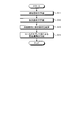
- FIG. 3 is a flowchart showing a method of manufacturing the cooling device shown in FIG.
- FIG. 4 is a diagram for explaining a method of manufacturing the cooling device shown in FIG.
- FIG. 5 is a diagram for explaining a method of manufacturing the cooling device shown in FIG.
- FIG. 6 is a schematic diagram showing an outline of a cold spray apparatus.
- FIG. 7 is a cross-sectional view illustrating the structure of the cooling device according to the first modification.
- FIG. 8 is a cross-sectional view illustrating the structure of the cooling device according to the second modification.
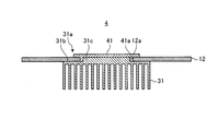
- FIG. 9 is a cross-sectional view illustrating the structure of the cooling device according to the third modification.
- FIG. 10 is a top view illustrating the structure of the cooling device according to the fourth modification.
- FIG. 1 is a perspective view showing a structure of a cooling device according to an embodiment of the present invention.
- FIG. 2 is a cross-sectional view taken along the line AA in FIG.
- the cooling device 1 includes a cooling member 11 provided with a heat medium channel 11 a for heat exchange in a member formed of metal or an alloy, and cooling.
- a plate-like member 12 disposed on one surface 11b of the member 11 (hereinafter also referred to as a plate-like member arrangement surface) and provided with an opening 12a exposing a part of the surface 11b, and the inside and surroundings of the opening 12a And a heat conductive layer 13 formed on the surface of the plate-like member 12.
- the cooling member 11 is formed of a member having good thermal conductivity, such as aluminum or aluminum alloy.
- the channel 11a is provided by subjecting such a member to excavation and the like, for example, by forming a part into a fin shape, for example.
- the cooling member 11 radiates the heat conducted from the heat conductive layer 13 to a heat medium such as cooling water or cooling gas flowing through the flow path 11a.
- the shape of the flow path 11a is not limited to that shown in FIGS. 1 and 2, and may be a desired shape. Moreover, it is good also considering only the surface of the cooling member 11 as a thermal radiation part, without providing a flow path inside the cooling member 11. FIG.
- the material of the cooling member 11 is pure aluminum (A1000 series, thermal conductivity: 220 to 235 W / (m ⁇ K)) or Al—Mg—Si based alloy (A6000 series). A6063 (thermal conductivity: 218 W / (m ⁇ K)) or the like subjected to annealing treatment) is used.
- the plate-like member 12 is formed of a metal or alloy having high mechanical strength such as an aluminum alloy. At least a part (all in FIG. 1) of the peripheral edge of the plate-like member 12 extends outward from the plate-like member arrangement surface 11b. This extended portion (extension portion) 12b is used as an attachment portion when the cooling device 1 is attached to, for example, a radiator that accommodates a heat medium.
- the size and shape of the opening 12a are not limited to those shown in FIG. 1, and may be a desired size and shape as long as they fit inside the plate-like member arrangement surface 11b.
- the area of the opening 12a is set as wide as possible so that the mechanical strength of the plate-like member 12 can be secured and a space for forming the heat conductive layer 13 on the plate-like member 12 can be sufficiently secured.
- 11 and the heat conductive layer 13 are preferably widened.
- the material of the plate-like member 12 is an Al—Cu based alloy (A2000 based) heat treated (tensile strength: 330 to 490 MPa, proof stress: 250 to 290 MPa), Al—Mn based alloy ( A3000 (working-hardened) (tensile strength: 150-220 MPa, yield strength: 130-200 MPa), Al-Mg alloy (A5000-based) work-hardened (tensile strength: 180-290 MPa, yield strength) : 130-260 MPa), Al—Mg—Si based alloy (A6000 based) heat treated (tensile strength: 180 to 380 MPa, yield strength: 140 to 320 MPa), Al—Zn—Mg—Cu based alloy (A7000) And the like subjected to heat treatment (tensile strength: 360 to 690 MPa, proof stress: 250 to 660 MPa).
- Al—Mn based alloy A3000 (working-hardened) (tensile strength: 150-220 MPa, yield strength: 130-200 MPa), Al
- the heat conductive layer 13 is formed of a metal or alloy having good heat conductivity, such as copper or a copper alloy.
- the heat conductive layer 13 has a contact surface 13a that comes into contact with a heat generation source such as a chip directly or through a substrate or the like when the cooling device 1 is attached to a radiator or the like, and through the contact surface 13a.
- a heat generation source such as a chip directly or through a substrate or the like when the cooling device 1 is attached to a radiator or the like, and through the contact surface 13a.
- the received heat is conducted to the cooling member 11.
- Such a heat conductive layer 13 is formed by a so-called cold spray method in which a powder of material (copper powder or the like) is accelerated together with a gas and sprayed and deposited on a base material in a solid state.
- the heat conductive layer 13 is continuously provided over the exposed portion 11 c exposed from the opening 12 a and the upper surface of the plate member 12 around the opening 12 a, and the cooling member
- FIG. 3 is a flowchart showing a method for manufacturing the cooling device 1.
- the cooling member 11 is manufactured by excavating aluminum or an aluminum alloy member into a desired shape (see FIG. 4).
- the plate-like member 12 is produced by providing an opening 12a in an aluminum alloy plate having a desired shape (see FIG. 4). At this time, in order to improve the mechanical strength of the plate member 12, the plate member 12 may be further subjected to heat treatment.
- step S13 the plate member 12 is arranged on the plate member arrangement surface 11b of the cooling member 11 (see FIGS. 4 and 5). At this time, the plate member 12 may be temporarily fixed to the cooling member 11 using a jig, an adhesive, or the like.
- step S14 the heat conductive layer 13 is formed by the cold spray method on the exposed portion 11c exposed from the opening 12a and the surface of the plate member 12 around the opening 12a in the plate member arrangement surface 11b.
- FIG. 6 is a schematic diagram showing an outline of a cold spray apparatus used for forming the heat conductive layer 13.
- the cold spray device 60 contains a gas heater 61 that heats the compressed gas and a powder of the material of the heat conductive layer 13 (hereinafter referred to as “material powder” or simply “powder”).
- the supplied powder supply device 62, the gas nozzle 64 for injecting the heated compressed gas and the material powder supplied thereto onto the base 67, and the supply amount of the compressed gas to the gas heater 61 and the powder supply device 62 are adjusted. Valves 65 and 66 are provided.
- the compressed gas helium, nitrogen, air or the like is used.
- the compressed gas supplied to the gas heater 61 is, for example, 50 ° C. or higher, heated to a temperature in a range lower than the melting point of the material powder, and then supplied to the spray gun 63.
- the heating temperature of the compressed gas is preferably 300 to 900 ° C.
- the compressed gas supplied to the powder supply device 62 supplies the material powder in the powder supply device 62 to the spray gun 63 so as to have a predetermined discharge amount.
- the heated compressed gas is made a supersonic flow (about 340 m / s or more) by the gas nozzle 64 having a divergent shape.
- the gas pressure of the compressed gas is preferably about 1 to 5 MPa. This is because the adhesion strength of the material powder to the base material 67 can be improved by adjusting the pressure of the compressed gas to this level. More preferably, the treatment is performed at a pressure of about 2 to 4 MPa.
- the material powder supplied to the spray gun 63 is accelerated by the injection of the compressed gas into the supersonic flow, and collides with the base material 67 at a high speed while being in a solid state, and forms a film.
- the apparatus is not limited to the cold spray apparatus 60 shown in FIG. 6 as long as the apparatus can form a film by colliding the material powder toward the base material 67 in a solid state.
- the cooling member 11 and the plate-like member 12 disposed thereon are set as the base material 67 to form a copper film (thermal conductive layer 13).
- a copper film is formed so as to be sufficiently thicker than the thickness of the plate member 12, and the copper film on the exposed portion 11 c and the copper film on the plate member 12 are integrated. Thereby, the cooling device 1 is completed.
- the heat conductive layer 13 is formed in the opening 12a (exposed portion 11c) of the plate-like member 12 disposed on the cooling member 11 and around it by the cold spray method.
- the film formed by the cold spray method has high thermal conductivity because there is no phase transformation and oxidation is suppressed.
- the cold spray method when the material powder collides with the base material (or the previously formed film), plastic deformation occurs between the powder and the base material, and an anchor effect is obtained. Since the coating is destroyed and metal bonds are formed between the new surfaces, the adhesive strength with the substrate is high. Therefore, since the heat conductive layer 13 itself has good heat conductivity and the heat conductive layer 13 is in close contact with the cooling member 11, good heat conductivity can be obtained between them.
- the cooling device 1 can achieve both the thermal conductivity required for the cooling member 11 and the mechanical strength required for the plate-like member 12.
- cooling member 11 and the plate-like member 12 are integrated, it is not necessary to perform a heat treatment or the like for improving the mechanical strength of the plate-like member 12. 11 and the plate-like member 12 can suppress the formation of intermetallic compounds that cause thermal resistance.
- the cooling member 11 and the plate-like member 12 are integrated by the heat conductive layer 13 formed by the cold spray method. Therefore, it is not necessary to separately provide a member or a process for fastening or joining the cooling member 11 and the plate-like member 12, and the number of parts can be reduced and the manufacturing process can be simplified.
- FIG. 7 is a cross-sectional view illustrating the structure of the cooling device according to the first modification.
- the end surface 21 b of the opening 21 a provided in the plate-like member 21 has a tapered shape that spreads from the cooling member 11 side toward the upper surface of the plate-like member 21.
- region (plate-shaped member 21 around the exposed part 11c and the opening 21a) which sprays material powder when forming the heat conductive layer 13 can be reduced, it is more uniform in thickness and density.
- the heat conductive layer 13 can be formed. In FIG. 7, the heat conductive layer 13 is formed only on the exposed portion 11c and the end surface 21b. However, the heat conductive layer 13 may be extended to the upper surface of the plate-like member 21 around the end surface 21b.
- FIG. 8 is a cross-sectional view illustrating the structure of the cooling device according to the second modification.
- excavation is performed on the peripheral edge portion 31 b except for the portion corresponding to the opening 12 a of the upper surface (plate member arrangement surface) 31 a of the cooling member 31 by the amount corresponding to the thickness of the plate member 12.
- a cutout is provided.
- FIG. 9 is a cross-sectional view illustrating the structure of the cooling device according to the third modification.
- the exposed portion 31c of the cooling member 31 is fitted into the opening 12a without any gap.
- the end surface of the exposed portion 31c and the opening 12a There may be a gap between the end face.
- the gap 41a between them is filled with a copper film, and the heat conductive layer 41 on the plate-like member 12 and the heat conductive layer 41 on the exposed portion 31c are integrated. You can do it.
- At least one of the end surface of the opening 12a and the end surface of the exposed portion 31c may be tapered so as to expand toward the upper surface of the plate-like member 12 as in the second modification.
- FIG. 10 is a top view illustrating the structure of the cooling device according to the fourth modification.
- the plate-like member provided with the opening is arranged on the cooling member.
- the cooling member 51 and the plate-like members 52, 53 are simultaneously formed by forming the heat conductive layer 54 by the cold spray method from the exposed portion 51a of the plate-like member arrangement surface to the plate-like members 52, 53. Can be integrated.
- the end surfaces of the plate-like members 52 and 53 may be tapered.
- a cutout may be provided on the upper surface of the cooling member 51 and the plate-like members 52 and 53 may be fitted into the cutout.
- Cooling device 11 31, 51 Cooling member 11a Flow path 11b Plate-like member arrangement surface 11c, 31c, 51a Exposed portion 12, 21, 52, 53 Plate-like member 12a, 21a Opening 13, 32, 41, 54 Heat Conductive layer 13a Contact surface 21b End surface 31b Peripheral portion 41a Clearance 60 Cold spray device 61 Gas heater 62 Powder supply device 63 Spray gun 64 Gas nozzle 65, 66 Valve 67 Base material
Landscapes
- Cooling Or The Like Of Semiconductors Or Solid State Devices (AREA)
Abstract
冷却装置をモジュール等に取り付けるために設けられる取り付け部の高い機械的強度と、冷却装置自体の良好な熱伝導性とを両立させた冷却装置及びその製造方法を提供する。冷却装置1は、アルミニウム又はアルミニウム合金によって形成された部材に熱媒体の流路11aを設けた冷却部材11と、アルミニウム合金によって形成され、冷却部材11の板状部材配置面11bに、冷却部材11の一部が露出するように配置された板状部材12と、板状部材12から冷却部材11の一部が露出している露出部分11c及びその周囲の板状部材12の表面に向け、銅又は銅合金からなる粉末をガスと共に加速し、固相状態のままで吹き付けて粉末を堆積させることによって形成された熱伝導層13とを備える。
Description
本発明は、冷却装置及びその製造方法に関する。
コンピュータのCPUやチップセット、AV機器や自動車用のパワートランジスタといった種々のモジュールや装置(以下、これらを総称してモジュール等という)には、モジュール等の過熱を防ぐために、通常、冷却装置が設けられる。冷却装置には、一例として、アルミニウム合金部材に熱媒体の移動経路を設けた冷却部材(ヒートシンク)が用いられる。ヒートシンクには、通常、銅等によって形成された熱伝導層が設けられており、チップ等から発生した熱を、熱伝導層を介して冷却部本体に移動させ外部に放熱することにより、モジュール等の冷却を行うことができる。
このような冷却装置においては、ヒートシンクから熱伝導層にかけての熱伝導性を高くする必要がある。このため、例えば、特許文献1においては、熱抵抗の要因となる金属間化合物の形成を防ぐために、アルミニウム製のヒートシンクに対してニッケルメッキを施した銅板をろう付することとしている。また、特許文献2においては、ヒートシンクの平板部上に、コールドスプレー等の溶射法により溶射金属層を直接形成した後、溶射金属層内の欠陥を低減するための熱処理を行っている。
ところで、このような冷却装置をモジュール等に取り付ける際には、例えば特許文献2の図8に示すように、ヒートシンク上部の平板部の端部を本体よりも外側に延出させ、この端部を熱交換媒体の容器である放熱器に架橋する場合がある。或いは、平板部の端部を放熱器に機械締結する場合もある。このため、平板部に対しては、高い機械的強度が要求される。
そこで、平板部の強度を向上させるため、アルミニウム又はアルミニウム合金からなる冷却部材にコールドスプレー法により銅の熱伝導層を設けた後、冷却装置全体に熱処理を施すことが考えられる。しかしながら、この場合、アルミニウム又はアルミニウム合金と銅との界面に金属間化合物が生成され、この界面における熱伝導性及び機械的信頼性が低下してしまうおそれがある。
或いは、冷却部材そのものを、予め硬化処理がなされた高強度アルミニウム合金によって作製することも考えられる。しかしながら、一般に、高強度アルミニウム合金の熱伝導率は、純アルミニウムや加工硬化させていないアルミニウム合金と比べてかなり低い(例えば、半分程度)ので、冷却部材自体の冷却効率が低下してしまう。
本発明は、上記に鑑みてなされたものであって、冷却部材に熱伝導層が設けられた冷却装置において、該冷却装置をモジュール等に取り付けるために設けられる取り付け部の高い機械的強度と、冷却装置自体の良好な熱伝導性とを両立させた冷却装置及びその製造方法を提供することを目的とする。
上述した課題を解決し、目的を達成するために、本発明に係る冷却装置は、金属又は合金によって形成された冷却部材と、金属又は合金によって形成され、前記冷却部材の1つの面に、前記冷却部材の一部が露出するように配置された板状部材と、前記板状部材から前記冷却部材の一部が露出している露出部分、及び少なくとも該露出部分の周囲の前記板状部材の表面に向け、金属又は合金からなる粉末をガスと共に加速し、固相状態のままで吹き付けて前記粉末を堆積させることによって形成された熱伝導層とを備えることを特徴とする。
上記冷却装置において、前記板状部材に、前記冷却部材の一部を露出させる開口が形成されていることを特徴とする。
上記冷却装置において、前記板状部材の少なくとも一部が、前記冷却部材の外周よりも外側に延出していることを特徴とする。
上記冷却装置において、前記露出部分の境界と接する前記板状部材の端面が、前記冷却部材側から前記板状部材の表面に向かって広がるテーパー状をなすことを特徴とする。
上記冷却装置において、前記冷却部材の板状部材配置面に、前記板状部材の厚さに等しく、前記板状部材が嵌合される切り欠きが設けられていることを特徴とする。
上記冷却装置において、前記冷却部材に、熱媒体の流路が設けられていることを特徴とする。
上記冷却装置において、前記冷却部材はアルミニウム又はアルミニウム合金によって形成され、前記板状部材はアルミニウム合金によって形成され、前記熱伝導層は銅又は銅合金によって形成されていることを特徴とする。
本発明に係る冷却装置の製造方法は、金属又は合金によって形成された冷却部材の1つの面に対し、金属又は合金によって形成された板状部材を、前記冷却部材の一部が露出するように配置する板状部材配置工程と、前記板状部材から前記冷却部材の一部が露出している露出部分、及び少なくとも該露出部分の周囲の前記板状部材の表面に向け、金属又は合金からなる粉末をガスと共に加速し、固相状態のままで吹き付けて前記粉末を堆積させることにより、熱伝導層を形成する熱伝導層形成工程とを含むことを特徴とする。
本発明によれば、冷却部材と板状部材とを別々に作製するので、冷却部材として熱伝導性の良好な材料を選択し、板状部材として、機械的強度の高い材料を選択することが可能になる。また、本発明によれば、板状部材から露出した冷却部材の部分及びその周囲の板状部材表面に、所謂コールドスプレー法により熱伝導層を形成するので、熱抵抗となる成分を介することなく冷却部材上に直接熱伝導層を形成することができ、それと同時に、冷却部材と板状部材とを一体化させることができる。従って、取り付け部の高い機械的強度と、冷却装置自体の良好な熱伝導性とを両立させた冷却装置を提供することが可能となる。
以下、本発明を実施するための形態を、図面を参照しながら詳細に説明する。なお、以下の実施の形態により本発明が限定されるものではない。また、以下の説明において参照する各図は、本発明の内容を理解し得る程度に形状、大きさ、及び位置関係を概略的に示してあるに過ぎない。即ち、本発明は各図で例示された形状、大きさ、及び位置関係のみに限定されるものではない。
(実施の形態)
図1は、本発明の一実施の形態に係る冷却装置の構造を示す斜視図である。また、図2は、図1のA-A断面図である。
図1及び図2に示すように、本実施の形態に係る冷却装置1は、金属又は合金によって形成された部材に、熱交換を行う熱媒体の流路11aを設けた冷却部材11と、冷却部材11の1つの面11b上(以下、板状部材配置面ともいう)に配置され、該面11bの一部を露出する開口12aが設けられた板状部材12と、開口12a内及びその周囲の板状部材12の表面に形成された熱伝導層13とを備える。
図1は、本発明の一実施の形態に係る冷却装置の構造を示す斜視図である。また、図2は、図1のA-A断面図である。
図1及び図2に示すように、本実施の形態に係る冷却装置1は、金属又は合金によって形成された部材に、熱交換を行う熱媒体の流路11aを設けた冷却部材11と、冷却部材11の1つの面11b上(以下、板状部材配置面ともいう)に配置され、該面11bの一部を露出する開口12aが設けられた板状部材12と、開口12a内及びその周囲の板状部材12の表面に形成された熱伝導層13とを備える。
冷却部材11は、例えばアルミニウムやアルミニウム合金のように、良好な熱伝導性を有する部材によって形成される。このような部材に掘削加工等を施し、一部を例えばフィン状とすることにより、流路11aが設けられる。冷却部材11は、熱伝導層13から伝導してきた熱を、流路11aを流通する冷却水や冷却ガス等の熱媒体に放熱する。
なお、流路11aの形状は、図1及び図2に示すものに限定されず、所望の形状として良い。また、冷却部材11の内側には流路を設けずに、冷却部材11の表面のみを放熱部としても良い。
冷却部材11の材料として、具体的には、Alが99%以上の純アルミニウム(A1000系、熱伝導率:220~235W/(m・K))や、Al-Mg-Si系合金(A6000系)に焼きなまし処理を施したA6063(熱伝導率:218W/(m・K))等が用いられる。
板状部材12は、例えばアルミニウム合金のように、機械的強度の高い金属又は合金によって形成される。板状部材12の周縁の少なくとも一部(図1においては全部)は、板状部材配置面11bよりも外側に延出している。この延出した部分(延出部)12bが、冷却装置1を例えば熱媒体を収容する放熱器等に取り付ける際に、取り付け部として用いられる。
なお、開口12aのサイズ及び形状は、図1に示すものに限定されず、板状部材配置面11bの内側に収まれば、所望のサイズ及び形状として良い。好ましくは、板状部材12の機械的強度を確保でき、且つ、板状部材12上に熱伝導層13を形成するスペースを十分に確保できる範囲で、開口12aの面積をなるべく広く取り、冷却部材11と熱伝導層13との接触面積を広くすると良い。
板状部材12の材料として、具体的には、Al-Cu系合金(A2000系)で熱処理を施したもの(引張り強さ:330~490MPa、耐力:250~290MPa)、Al-Mn系合金(A3000系)で加工硬化させたもの(引張り強さ:150~220MPa、耐力:130~200MPa)、Al-Mg系合金(A5000系)で加工硬化させたもの(引張り強さ:180~290MPa、耐力:130~260MPa)、Al-Mg-Si系合金(A6000系)で熱処理を施したもの(引張り強さ:180~380MPa、耐力:140~320MPa)、Al-Zn-Mg-Cu系合金(A7000系)で熱処理を施したもの(引張り強さ:360~690MPa、耐力:250~660MPa)等が用いられる。
熱伝導層13は、例えば銅又は銅合金のように、良好な熱伝導性を有する金属又は合金によって形成される。熱伝導層13は、冷却装置1を例えば放熱器等に取り付けた際に、チップ等の熱発生源と直接又は基板等を介して接触する接触面13aを有し、この接触面13aを介して受け取った熱を冷却部材11に伝導する。このような熱伝導層13は、材料の粉末(銅粉等)をガスと共に加速し、基材に固相状態のままで吹き付けて堆積させる、所謂コールドスプレー法により形成されている。熱伝導層13は、板状部材配置面11bの内、開口12aから露出した露出部分11cと、開口12a周囲の板状部材12の上面とに渡って連続的に設けられており、冷却部材11と板状部材12とを互いに一体化させている。
次に、冷却装置1の製造方法について説明する。図3は、冷却装置1の製造方法を示すフローチャートである。
まず、工程S11において、アルミニウム又はアルミニウム合金部材を所望の形状に掘削加工することにより、冷却部材11を作製する(図4参照)。
まず、工程S11において、アルミニウム又はアルミニウム合金部材を所望の形状に掘削加工することにより、冷却部材11を作製する(図4参照)。
続く工程S12において、所望の形状のアルミニウム合金板に開口12aを設けることにより、板状部材12を作製する(図4参照)。この際、板状部材12の機械的強度を向上させるため、板状部材12にさらに熱処理を施しても良い。
工程S13において、冷却部材11の板状部材配置面11b上に板状部材12を配置する(図4及び図5参照)。この際、治具や接着剤等を用いて板状部材12を冷却部材11に仮固定すると良い。
工程S14において、板状部材配置面11bの内、開口12aから露出した露出部分11c及び開口12a周囲の板状部材12の表面に、コールドスプレー法によって熱伝導層13を形成する。
図6は、熱伝導層13の形成に使用されるコールドスプレー装置の概要を示す模式図である。図6に示すように、コールドスプレー装置60は、圧縮ガスを加熱するガス加熱器61と、熱伝導層13の材料の粉末(以下、材料粉末又は単に粉末という)を収容し、スプレーガン63に供給する粉末供給装置62と、加熱された圧縮ガス及びそこに供給された材料粉末を基材67に噴射するガスノズル64と、ガス加熱器61及び粉末供給装置62に対する圧縮ガスの供給量をそれぞれ調節するバルブ65及び66とを備える。
圧縮ガスとしては、ヘリウム、窒素、空気などが使用される。ガス加熱器61に供給された圧縮ガスは、例えば50℃以上であって、材料粉末の融点よりも低い範囲の温度に加熱された後、スプレーガン63に供給される。圧縮ガスの加熱温度は、好ましくは300~900℃である。
一方、粉末供給装置62に供給された圧縮ガスは、粉末供給装置62内の材料粉末をスプレーガン63に所定の吐出量となるように供給する。
加熱された圧縮ガスは末広形状をなすガスノズル64により超音速流(約340m/s以上)にされる。この際の圧縮ガスのガス圧力は、1~5MPa程度とすることが好ましい。圧縮ガスの圧力をこの程度に調整することにより、基材67に対する材料粉末の密着強度の向上を図ることができるからである。より好ましくは、2~4MPa程度の圧力で処理すると良い。スプレーガン63に供給された材料粉末は、この圧縮ガスの超音速流の中への投入により加速され、固相状態のまま基材67に高速で衝突して堆積し、皮膜を形成する。なお、材料粉末を基材67に向けて固相状態のまま衝突させて皮膜を形成できる装置であれば、図6に示すコールドスプレー装置60に限定されるものではない。
このようなコールドスプレー装置60において、基材67として冷却部材11及びその上に配置した板状部材12をセットして、銅皮膜(熱伝導層13)を形成する。この際、板状部材12の厚さよりも十分厚くなるように銅皮膜を形成し、露出部分11c上の銅皮膜と板状部材12上の銅皮膜とを一体化させる。それにより、冷却装置1が完成する。
以上説明したように、本実施の形態によれば、冷却部材11上に配置した板状部材12の開口12a内(露出部分11c)及びその周囲に、コールドスプレー法により熱伝導層13を形成する。ここで、コールドスプレー法によって形成された皮膜は、相変態がなく酸化も抑制されているため、高い熱伝導性を有する。また、コールドスプレー法においては、材料粉末が基材(又は先に形成された皮膜)に衝突した際に粉末と基材との間で塑性変形が生じてアンカー効果が得られると共に、互いの酸化皮膜が破壊されて新生面同士による金属結合が生じるので、基材との密着強度も高いという特徴を有する。従って、熱伝導層13自体が良好な熱伝導性を有すると共に、熱伝導層13が冷却部材11と強く密着しているため、両者の間においても、良好な熱伝導性を得ることができる。
また、本実施の形態によれば、冷却部材11と板状部材12とで、それぞれの機能に適した材料を別個に選択することができる。従って、冷却部材11に必要な熱伝導性と、板状部材12に必要な機械的強度とを、冷却装置1において両立させることができる。
また、本実施の形態によれば、冷却部材11と板状部材12とを一体化させた後、板状部材12の機械的強度を向上させるための熱処理等を行う必要がないので、冷却部材11と板状部材12との間において熱抵抗の要因となる金属間化合物の生成を抑制することができる。
また、本実施の形態においては、コールドスプレー法により形成した熱伝導層13によって、冷却部材11と板状部材12とを一体化させる。従って、冷却部材11と板状部材12とを締結又は接合するための部材や工程を別途設ける必要がなくなり、部品点数を削減し、製造工程を簡素化することが可能となる。
以下、本実施の形態の変形例1~4について説明する。なお、各変形例1~4における冷却部材、板状部材、及び熱伝導層の材料については、上記実施の形態において説明したものと同様である。
(変形例1)
図7は、変形例1に係る冷却装置の構造を示す断面図である。図7に示す冷却装置2においては、板状部材21に設けた開口21aの端面21bを、冷却部材11側から板状部材21の上面に向かって広がるテーパー状としている。この場合、熱伝導層13を形成する際に材料粉末を吹き付ける領域(露出部分11c及び開口21a周囲の板状部材21)に生じる段差を低減することができるので、厚さや密度において、より均一な熱伝導層13を形成することができる。なお、図7においては、露出部分11c及び端面21bのみに熱伝導層13を形成しているが、端面21bの周囲の板状部材21上面まで熱伝導層13を拡張しても良い。
図7は、変形例1に係る冷却装置の構造を示す断面図である。図7に示す冷却装置2においては、板状部材21に設けた開口21aの端面21bを、冷却部材11側から板状部材21の上面に向かって広がるテーパー状としている。この場合、熱伝導層13を形成する際に材料粉末を吹き付ける領域(露出部分11c及び開口21a周囲の板状部材21)に生じる段差を低減することができるので、厚さや密度において、より均一な熱伝導層13を形成することができる。なお、図7においては、露出部分11c及び端面21bのみに熱伝導層13を形成しているが、端面21bの周囲の板状部材21上面まで熱伝導層13を拡張しても良い。
(変形例2)
図8は、変形例2に係る冷却装置の構造を示す断面図である。図8に示す冷却装置3においては、冷却部材31の上面(板状部材配置面)31aの開口12aに対応する部分を除く周縁部31bに、板状部材12の厚さに対応する分だけ掘削した切り欠きを設けている。それにより、板状部材12を冷却部材31上に配置する際に、露出部分31cを開口12aに嵌合させ、露出部分31cの上面と板状部材12の上面との高さを揃えている。この場合、厚さ及び密度において、より均一な熱伝導層32を形成することができる。
図8は、変形例2に係る冷却装置の構造を示す断面図である。図8に示す冷却装置3においては、冷却部材31の上面(板状部材配置面)31aの開口12aに対応する部分を除く周縁部31bに、板状部材12の厚さに対応する分だけ掘削した切り欠きを設けている。それにより、板状部材12を冷却部材31上に配置する際に、露出部分31cを開口12aに嵌合させ、露出部分31cの上面と板状部材12の上面との高さを揃えている。この場合、厚さ及び密度において、より均一な熱伝導層32を形成することができる。
(変形例3)
図9は、変形例3に係る冷却装置の構造を示す断面図である。
図8に示す冷却装置3においては、冷却部材31の露出部分31cを開口12aに隙間なく嵌合させているが、図9に示す冷却装置4のように、露出部分31cの端面と開口12aの端面との間に隙間があっても構わない。この場合、熱伝導層41を形成する際に、両者の間の隙間41aを銅皮膜で充填し、板状部材12上の熱伝導層41と露出部分31c上の熱伝導層41とを一体化させれば良い。
図9は、変形例3に係る冷却装置の構造を示す断面図である。
図8に示す冷却装置3においては、冷却部材31の露出部分31cを開口12aに隙間なく嵌合させているが、図9に示す冷却装置4のように、露出部分31cの端面と開口12aの端面との間に隙間があっても構わない。この場合、熱伝導層41を形成する際に、両者の間の隙間41aを銅皮膜で充填し、板状部材12上の熱伝導層41と露出部分31c上の熱伝導層41とを一体化させれば良い。
また、さらなる変形例として、開口12aの端面と露出部分31cの端面との内の少なくとも一方を、変形例2と同様に、板状部材12の上面に向かって広がるテーパー状にしても良い。
(変形例4)
図10は、変形例4に係る冷却装置の構造を示す上面図である。
上述した実施の形態及び変形例1~3においては、開口を設けた板状部材を冷却部材上に配置した。しかしながら、板状部材を配置した際に、冷却部材の板状部材配置面の一部を露出させることができれば、必ずしも板状部材に開口を設ける必要はない。
図10は、変形例4に係る冷却装置の構造を示す上面図である。
上述した実施の形態及び変形例1~3においては、開口を設けた板状部材を冷却部材上に配置した。しかしながら、板状部材を配置した際に、冷却部材の板状部材配置面の一部を露出させることができれば、必ずしも板状部材に開口を設ける必要はない。
例えば、図10に示す冷却装置5のように、冷却部材51の板状部材配置面に板状部材52、53を、互いに間隔を開けて配置することにより、板状部材配置面の一部を露出させることができる。この場合、板状部材配置面の露出部分51aから板状部材52、53に渡って、コールドスプレー法により熱伝導層54を形成することにより、同時に、冷却部材51と板状部材52、53とを一体化させることができる。
なお、変形例4においても、変形例1と同様に、板状部材52、53の端面をテーパー状としても良い。また、変形例2、3と同様に、冷却部材51の上面に切り欠きを設け、当該切り欠きに板状部材52、53を嵌合させるようにしても良い。
1~5 冷却装置
11、31、51 冷却部材
11a 流路
11b 板状部材配置面
11c、31c、51a 露出部分
12、21、52、53 板状部材
12a、21a 開口
13、32、41、54 熱伝導層
13a 接触面
21b 端面
31b 周縁部
41a 隙間
60 コールドスプレー装置
61 ガス加熱器
62 粉末供給装置
63 スプレーガン
64 ガスノズル
65、66 バルブ
67 基材
11、31、51 冷却部材
11a 流路
11b 板状部材配置面
11c、31c、51a 露出部分
12、21、52、53 板状部材
12a、21a 開口
13、32、41、54 熱伝導層
13a 接触面
21b 端面
31b 周縁部
41a 隙間
60 コールドスプレー装置
61 ガス加熱器
62 粉末供給装置
63 スプレーガン
64 ガスノズル
65、66 バルブ
67 基材
Claims (8)
- 金属又は合金によって形成された冷却部材と、
金属又は合金によって形成され、前記冷却部材の1つの面に、前記冷却部材の一部が露出するように配置された板状部材と、
前記板状部材から前記冷却部材の一部が露出している露出部分、及び少なくとも該露出部分の周囲の前記板状部材の表面に向け、金属又は合金からなる粉末をガスと共に加速し、固相状態のままで吹き付けて前記粉末を堆積させることによって形成された熱伝導層と、
を備えることを特徴とする冷却装置。 - 前記板状部材に、前記冷却部材の一部を露出させる開口が形成されていることを特徴とする請求項1に記載の冷却装置。
- 前記板状部材の少なくとも一部が、前記冷却部材の外周よりも外側に延出していることを特徴とする請求項1又は2に記載の冷却装置。
- 前記露出部分の境界と接する前記板状部材の端面が、前記冷却部材側から前記板状部材の表面に向かって広がるテーパー状をなすことを特徴とする請求項1~3のいずれか1項に記載の冷却装置。
- 前記冷却部材の板状部材配置面に、前記板状部材の厚さに等しく、前記板状部材が嵌合される切り欠きが設けられていることを特徴とする請求項1~3のいずれか1項に記載の冷却装置。
- 前記冷却部材に、熱媒体の流路が設けられていることを特徴とする請求項1~5のいずれか1項に記載の冷却装置。
- 前記冷却部材はアルミニウム又はアルミニウム合金によって形成され、
前記板状部材はアルミニウム合金によって形成され、
前記熱伝導層は銅又は銅合金によって形成されていることを特徴とする請求項1~6のいずれか1項に記載の冷却装置。 - 金属又は合金によって形成された冷却部材の1つの面に対し、金属又は合金によって形成された板状部材を、前記冷却部材の一部が露出するように配置する板状部材配置工程と、
前記板状部材から前記冷却部材の一部が露出している露出部分、及び少なくとも該露出部分の周囲の前記板状部材の表面に向け、金属又は合金からなる粉末をガスと共に加速し、固相状態のままで吹き付けて前記粉末を堆積させることにより、熱伝導層を形成する熱伝導層形成工程と、
を含むことを特徴とする冷却装置の製造方法。
Applications Claiming Priority (2)
| Application Number | Priority Date | Filing Date | Title |
|---|---|---|---|
| JP2011172148A JP2013038183A (ja) | 2011-08-05 | 2011-08-05 | 冷却装置及びその製造方法 |
| JP2011-172148 | 2011-08-05 |
Publications (1)
| Publication Number | Publication Date |
|---|---|
| WO2013021870A1 true WO2013021870A1 (ja) | 2013-02-14 |
Family
ID=47668382
Family Applications (1)
| Application Number | Title | Priority Date | Filing Date |
|---|---|---|---|
| PCT/JP2012/069501 Ceased WO2013021870A1 (ja) | 2011-08-05 | 2012-07-31 | 冷却装置及びその製造方法 |
Country Status (2)
| Country | Link |
|---|---|
| JP (1) | JP2013038183A (ja) |
| WO (1) | WO2013021870A1 (ja) |
Cited By (5)
| Publication number | Priority date | Publication date | Assignee | Title |
|---|---|---|---|---|
| WO2015019890A1 (ja) * | 2013-08-05 | 2015-02-12 | 日本発條株式会社 | 放熱板、パワーモジュールおよび放熱板の製造方法 |
| WO2018076646A1 (zh) * | 2016-10-28 | 2018-05-03 | 曙光信息产业(北京)有限公司 | 一种冷却装置及其制造方法 |
| EP3933913A1 (de) * | 2020-06-30 | 2022-01-05 | Siemens Aktiengesellschaft | Leistungsmodul mit mindestens zwei leistungseinheiten |
| CN115981085A (zh) * | 2021-10-15 | 2023-04-18 | 中强光电股份有限公司 | 转轮的制造方法、转轮以及投影装置 |
| EP4345886A1 (de) * | 2022-09-28 | 2024-04-03 | Siemens Aktiengesellschaft | Verfahren zur herstellung eines halbleitermoduls mit mindestens einer halbleiteranordnung und einem kühlkörper |
Families Citing this family (2)
| Publication number | Priority date | Publication date | Assignee | Title |
|---|---|---|---|---|
| JP2016103619A (ja) * | 2014-11-27 | 2016-06-02 | Cbcエスト株式会社 | 冷却デバイス用ヒートシンクおよびその製造方法ならびにそれを用いた電子冷却装置 |
| DE112014007285B4 (de) * | 2014-12-26 | 2024-01-18 | Mitsubishi Electric Corporation | Halbleitermodul |
Citations (4)
| Publication number | Priority date | Publication date | Assignee | Title |
|---|---|---|---|---|
| JP2008124158A (ja) * | 2006-11-10 | 2008-05-29 | Fuji Electric Device Technology Co Ltd | 絶縁基板およびその製造方法、ならびに半導体装置の製造方法 |
| JP2009032996A (ja) * | 2007-07-28 | 2009-02-12 | Sumitomo Electric Ind Ltd | 放熱構造体の製造方法 |
| JP2011238705A (ja) * | 2010-05-07 | 2011-11-24 | Nhk Spring Co Ltd | 温度調節装置、冷却装置、及び温度調節装置の製造方法 |
| WO2012093614A1 (ja) * | 2011-01-07 | 2012-07-12 | 日本発條株式会社 | 導電部材 |
-
2011
- 2011-08-05 JP JP2011172148A patent/JP2013038183A/ja not_active Withdrawn
-
2012
- 2012-07-31 WO PCT/JP2012/069501 patent/WO2013021870A1/ja not_active Ceased
Patent Citations (4)
| Publication number | Priority date | Publication date | Assignee | Title |
|---|---|---|---|---|
| JP2008124158A (ja) * | 2006-11-10 | 2008-05-29 | Fuji Electric Device Technology Co Ltd | 絶縁基板およびその製造方法、ならびに半導体装置の製造方法 |
| JP2009032996A (ja) * | 2007-07-28 | 2009-02-12 | Sumitomo Electric Ind Ltd | 放熱構造体の製造方法 |
| JP2011238705A (ja) * | 2010-05-07 | 2011-11-24 | Nhk Spring Co Ltd | 温度調節装置、冷却装置、及び温度調節装置の製造方法 |
| WO2012093614A1 (ja) * | 2011-01-07 | 2012-07-12 | 日本発條株式会社 | 導電部材 |
Cited By (12)
| Publication number | Priority date | Publication date | Assignee | Title |
|---|---|---|---|---|
| WO2015019890A1 (ja) * | 2013-08-05 | 2015-02-12 | 日本発條株式会社 | 放熱板、パワーモジュールおよび放熱板の製造方法 |
| JP2015032758A (ja) * | 2013-08-05 | 2015-02-16 | 日本発條株式会社 | 放熱板、パワーモジュールおよび放熱板の製造方法 |
| TWI566344B (zh) * | 2013-08-05 | 2017-01-11 | 日本發條股份有限公司 | 散熱板、功率模組及散熱板的製造方法 |
| WO2018076646A1 (zh) * | 2016-10-28 | 2018-05-03 | 曙光信息产业(北京)有限公司 | 一种冷却装置及其制造方法 |
| EP3933913A1 (de) * | 2020-06-30 | 2022-01-05 | Siemens Aktiengesellschaft | Leistungsmodul mit mindestens zwei leistungseinheiten |
| WO2022002464A1 (de) * | 2020-06-30 | 2022-01-06 | Siemens Aktiengesellschaft | Leistungsmodul mit mindestens drei leistungseinheiten |
| US12593729B2 (en) | 2020-06-30 | 2026-03-31 | Siemens Aktiengesellschaft | Power module having at least three power units |
| CN115981085A (zh) * | 2021-10-15 | 2023-04-18 | 中强光电股份有限公司 | 转轮的制造方法、转轮以及投影装置 |
| US20230117624A1 (en) * | 2021-10-15 | 2023-04-20 | Coretronic Corporation | Wheel manufacturing method, wheel, and projection apparatus |
| US12498624B2 (en) * | 2021-10-15 | 2025-12-16 | Coretronic Corporation | Wheel manufacturing method, wheel, and projection apparatus |
| CN115981085B (zh) * | 2021-10-15 | 2026-04-28 | 中强光电股份有限公司 | 转轮的制造方法、转轮以及投影装置 |
| EP4345886A1 (de) * | 2022-09-28 | 2024-04-03 | Siemens Aktiengesellschaft | Verfahren zur herstellung eines halbleitermoduls mit mindestens einer halbleiteranordnung und einem kühlkörper |
Also Published As
| Publication number | Publication date |
|---|---|
| JP2013038183A (ja) | 2013-02-21 |
Similar Documents
| Publication | Publication Date | Title |
|---|---|---|
| WO2013021870A1 (ja) | 冷却装置及びその製造方法 | |
| KR101585142B1 (ko) | 방열 구조체, 파워 모듈, 방열 구조체의 제조 방법 및 파워 모듈의 제조 방법 | |
| EP2592647B1 (en) | Manufacturing method for plate | |
| KR101572586B1 (ko) | 적층체 및 적층체의 제조 방법 | |
| KR101343289B1 (ko) | 반도체 장치 및 그 제조 방법 | |
| EP2455512A1 (en) | Masking jig, substrate heating apparatus, and film formation method | |
| JP2013089799A (ja) | 放熱用フィン付き回路基板の製造方法 | |
| US20210175146A1 (en) | Heat Sink for an Electronic Component | |
| KR101550345B1 (ko) | 온도 조절 장치 및 이 온도 조절 장치의 제조 방법 | |
| TWI566344B (zh) | 散熱板、功率模組及散熱板的製造方法 | |
| JPWO2016021561A1 (ja) | 複合基板及びパワーモジュール | |
| JP2009032996A (ja) | 放熱構造体の製造方法 | |
| JP5734129B2 (ja) | 流路付き部材及びその製造方法 | |
| KR101258598B1 (ko) | 방열핀이 접합된 인쇄회로기판 및 방열핀 접합방법 | |
| JP2012004252A (ja) | シャフト付きヒータユニットおよびシャフト付きヒータユニット製造方法 | |
| JP2009043814A (ja) | 放熱構造体の製造方法 | |
| CN109564898B (zh) | 半导体模块及其生产方法 | |
| TWI484557B (zh) | 附有流路之構件及該構件之製造方法 | |
| JP6299578B2 (ja) | 半導体装置 | |
| KR101242610B1 (ko) | 전자부품 방열용 냉각기판 및 그 제조방법 | |
| JP7722817B2 (ja) | 積層体の製造方法 | |
| KR20240131921A (ko) | 저온분사 적층을 포함한 방열판 |
Legal Events
| Date | Code | Title | Description |
|---|---|---|---|
| 121 | Ep: the epo has been informed by wipo that ep was designated in this application |
Ref document number: 12822207 Country of ref document: EP Kind code of ref document: A1 |
|
| NENP | Non-entry into the national phase |
Ref country code: DE |
|
| 122 | Ep: pct application non-entry in european phase |
Ref document number: 12822207 Country of ref document: EP Kind code of ref document: A1 |