WO2013018473A1 - Metal foil with coating layer and method for producing same, secondary cell electrode and method for producing same, and lithium ion secondary cell - Google Patents
Metal foil with coating layer and method for producing same, secondary cell electrode and method for producing same, and lithium ion secondary cell Download PDFInfo
- Publication number
- WO2013018473A1 WO2013018473A1 PCT/JP2012/066439 JP2012066439W WO2013018473A1 WO 2013018473 A1 WO2013018473 A1 WO 2013018473A1 JP 2012066439 W JP2012066439 W JP 2012066439W WO 2013018473 A1 WO2013018473 A1 WO 2013018473A1
- Authority
- WO
- WIPO (PCT)
- Prior art keywords
- layer
- active material
- metal foil
- coating layer
- resin composition
- Prior art date
Links
Images


Classifications
-
- H—ELECTRICITY
- H01—ELECTRIC ELEMENTS
- H01M—PROCESSES OR MEANS, e.g. BATTERIES, FOR THE DIRECT CONVERSION OF CHEMICAL ENERGY INTO ELECTRICAL ENERGY
- H01M4/00—Electrodes
- H01M4/02—Electrodes composed of, or comprising, active material
- H01M4/64—Carriers or collectors
- H01M4/66—Selection of materials
- H01M4/661—Metal or alloys, e.g. alloy coatings
-
- C—CHEMISTRY; METALLURGY
- C25—ELECTROLYTIC OR ELECTROPHORETIC PROCESSES; APPARATUS THEREFOR
- C25D—PROCESSES FOR THE ELECTROLYTIC OR ELECTROPHORETIC PRODUCTION OF COATINGS; ELECTROFORMING; APPARATUS THEREFOR
- C25D15/00—Electrolytic or electrophoretic production of coatings containing embedded materials, e.g. particles, whiskers, wires
-
- C—CHEMISTRY; METALLURGY
- C25—ELECTROLYTIC OR ELECTROPHORETIC PROCESSES; APPARATUS THEREFOR
- C25D—PROCESSES FOR THE ELECTROLYTIC OR ELECTROPHORETIC PRODUCTION OF COATINGS; ELECTROFORMING; APPARATUS THEREFOR
- C25D5/00—Electroplating characterised by the process; Pretreatment or after-treatment of workpieces
- C25D5/48—After-treatment of electroplated surfaces
-
- C—CHEMISTRY; METALLURGY
- C25—ELECTROLYTIC OR ELECTROPHORETIC PROCESSES; APPARATUS THEREFOR
- C25D—PROCESSES FOR THE ELECTROLYTIC OR ELECTROPHORETIC PRODUCTION OF COATINGS; ELECTROFORMING; APPARATUS THEREFOR
- C25D5/00—Electroplating characterised by the process; Pretreatment or after-treatment of workpieces
- C25D5/60—Electroplating characterised by the structure or texture of the layers
- C25D5/605—Surface topography of the layers, e.g. rough, dendritic or nodular layers
-
- C—CHEMISTRY; METALLURGY
- C25—ELECTROLYTIC OR ELECTROPHORETIC PROCESSES; APPARATUS THEREFOR
- C25D—PROCESSES FOR THE ELECTROLYTIC OR ELECTROPHORETIC PRODUCTION OF COATINGS; ELECTROFORMING; APPARATUS THEREFOR
- C25D5/00—Electroplating characterised by the process; Pretreatment or after-treatment of workpieces
- C25D5/60—Electroplating characterised by the structure or texture of the layers
- C25D5/615—Microstructure of the layers, e.g. mixed structure
- C25D5/617—Crystalline layers
-
- C—CHEMISTRY; METALLURGY
- C25—ELECTROLYTIC OR ELECTROPHORETIC PROCESSES; APPARATUS THEREFOR
- C25D—PROCESSES FOR THE ELECTROLYTIC OR ELECTROPHORETIC PRODUCTION OF COATINGS; ELECTROFORMING; APPARATUS THEREFOR
- C25D7/00—Electroplating characterised by the article coated
- C25D7/06—Wires; Strips; Foils
- C25D7/0614—Strips or foils
- C25D7/0628—In vertical cells
-
- H—ELECTRICITY
- H01—ELECTRIC ELEMENTS
- H01M—PROCESSES OR MEANS, e.g. BATTERIES, FOR THE DIRECT CONVERSION OF CHEMICAL ENERGY INTO ELECTRICAL ENERGY
- H01M10/00—Secondary cells; Manufacture thereof
- H01M10/05—Accumulators with non-aqueous electrolyte
- H01M10/052—Li-accumulators
- H01M10/0525—Rocking-chair batteries, i.e. batteries with lithium insertion or intercalation in both electrodes; Lithium-ion batteries
-
- C—CHEMISTRY; METALLURGY
- C25—ELECTROLYTIC OR ELECTROPHORETIC PROCESSES; APPARATUS THEREFOR
- C25D—PROCESSES FOR THE ELECTROLYTIC OR ELECTROPHORETIC PRODUCTION OF COATINGS; ELECTROFORMING; APPARATUS THEREFOR
- C25D1/00—Electroforming
- C25D1/04—Wires; Strips; Foils
-
- C—CHEMISTRY; METALLURGY
- C25—ELECTROLYTIC OR ELECTROPHORETIC PROCESSES; APPARATUS THEREFOR
- C25D—PROCESSES FOR THE ELECTROLYTIC OR ELECTROPHORETIC PRODUCTION OF COATINGS; ELECTROFORMING; APPARATUS THEREFOR
- C25D3/00—Electroplating: Baths therefor
- C25D3/02—Electroplating: Baths therefor from solutions
- C25D3/38—Electroplating: Baths therefor from solutions of copper
-
- H—ELECTRICITY
- H01—ELECTRIC ELEMENTS
- H01M—PROCESSES OR MEANS, e.g. BATTERIES, FOR THE DIRECT CONVERSION OF CHEMICAL ENERGY INTO ELECTRICAL ENERGY
- H01M4/00—Electrodes
- H01M4/02—Electrodes composed of, or comprising, active material
- H01M4/36—Selection of substances as active materials, active masses, active liquids
- H01M4/38—Selection of substances as active materials, active masses, active liquids of elements or alloys
- H01M4/386—Silicon or alloys based on silicon
-
- H—ELECTRICITY
- H01—ELECTRIC ELEMENTS
- H01M—PROCESSES OR MEANS, e.g. BATTERIES, FOR THE DIRECT CONVERSION OF CHEMICAL ENERGY INTO ELECTRICAL ENERGY
- H01M4/00—Electrodes
- H01M4/02—Electrodes composed of, or comprising, active material
- H01M4/36—Selection of substances as active materials, active masses, active liquids
- H01M4/38—Selection of substances as active materials, active masses, active liquids of elements or alloys
- H01M4/387—Tin or alloys based on tin
-
- H—ELECTRICITY
- H01—ELECTRIC ELEMENTS
- H01M—PROCESSES OR MEANS, e.g. BATTERIES, FOR THE DIRECT CONVERSION OF CHEMICAL ENERGY INTO ELECTRICAL ENERGY
- H01M4/00—Electrodes
- H01M4/02—Electrodes composed of, or comprising, active material
- H01M4/36—Selection of substances as active materials, active masses, active liquids
- H01M4/48—Selection of substances as active materials, active masses, active liquids of inorganic oxides or hydroxides
- H01M4/485—Selection of substances as active materials, active masses, active liquids of inorganic oxides or hydroxides of mixed oxides or hydroxides for inserting or intercalating light metals, e.g. LiTi2O4 or LiTi2OxFy
-
- H—ELECTRICITY
- H01—ELECTRIC ELEMENTS
- H01M—PROCESSES OR MEANS, e.g. BATTERIES, FOR THE DIRECT CONVERSION OF CHEMICAL ENERGY INTO ELECTRICAL ENERGY
- H01M4/00—Electrodes
- H01M4/02—Electrodes composed of, or comprising, active material
- H01M4/36—Selection of substances as active materials, active masses, active liquids
- H01M4/48—Selection of substances as active materials, active masses, active liquids of inorganic oxides or hydroxides
- H01M4/50—Selection of substances as active materials, active masses, active liquids of inorganic oxides or hydroxides of manganese
- H01M4/505—Selection of substances as active materials, active masses, active liquids of inorganic oxides or hydroxides of manganese of mixed oxides or hydroxides containing manganese for inserting or intercalating light metals, e.g. LiMn2O4 or LiMn2OxFy
-
- H—ELECTRICITY
- H01—ELECTRIC ELEMENTS
- H01M—PROCESSES OR MEANS, e.g. BATTERIES, FOR THE DIRECT CONVERSION OF CHEMICAL ENERGY INTO ELECTRICAL ENERGY
- H01M4/00—Electrodes
- H01M4/02—Electrodes composed of, or comprising, active material
- H01M4/36—Selection of substances as active materials, active masses, active liquids
- H01M4/48—Selection of substances as active materials, active masses, active liquids of inorganic oxides or hydroxides
- H01M4/52—Selection of substances as active materials, active masses, active liquids of inorganic oxides or hydroxides of nickel, cobalt or iron
- H01M4/525—Selection of substances as active materials, active masses, active liquids of inorganic oxides or hydroxides of nickel, cobalt or iron of mixed oxides or hydroxides containing iron, cobalt or nickel for inserting or intercalating light metals, e.g. LiNiO2, LiCoO2 or LiCoOxFy
-
- H—ELECTRICITY
- H01—ELECTRIC ELEMENTS
- H01M—PROCESSES OR MEANS, e.g. BATTERIES, FOR THE DIRECT CONVERSION OF CHEMICAL ENERGY INTO ELECTRICAL ENERGY
- H01M4/00—Electrodes
- H01M4/02—Electrodes composed of, or comprising, active material
- H01M4/36—Selection of substances as active materials, active masses, active liquids
- H01M4/58—Selection of substances as active materials, active masses, active liquids of inorganic compounds other than oxides or hydroxides, e.g. sulfides, selenides, tellurides, halogenides or LiCoFy; of polyanionic structures, e.g. phosphates, silicates or borates
- H01M4/583—Carbonaceous material, e.g. graphite-intercalation compounds or CFx
- H01M4/587—Carbonaceous material, e.g. graphite-intercalation compounds or CFx for inserting or intercalating light metals
-
- Y—GENERAL TAGGING OF NEW TECHNOLOGICAL DEVELOPMENTS; GENERAL TAGGING OF CROSS-SECTIONAL TECHNOLOGIES SPANNING OVER SEVERAL SECTIONS OF THE IPC; TECHNICAL SUBJECTS COVERED BY FORMER USPC CROSS-REFERENCE ART COLLECTIONS [XRACs] AND DIGESTS
- Y02—TECHNOLOGIES OR APPLICATIONS FOR MITIGATION OR ADAPTATION AGAINST CLIMATE CHANGE
- Y02E—REDUCTION OF GREENHOUSE GAS [GHG] EMISSIONS, RELATED TO ENERGY GENERATION, TRANSMISSION OR DISTRIBUTION
- Y02E60/00—Enabling technologies; Technologies with a potential or indirect contribution to GHG emissions mitigation
- Y02E60/10—Energy storage using batteries
Definitions
- the present invention relates to a metal foil with a coating layer that is particularly excellent as an electrode for a lithium ion secondary battery. Moreover, this invention relates to the electrode for secondary batteries using the said metal foil with a coating layer, and the lithium ion secondary battery using this electrode.
- Lithium ion secondary batteries are used as an indispensable power source for mobile phones, mobile terminals, laptop computers and the like.
- Copper foil is generally used for the current collector on the negative electrode side of the lithium ion secondary battery.
- carbon particles are applied as a negative electrode active material layer on the surface of a copper foil having a smooth front and back, and further pressed to form a negative electrode.
- An electrolytic copper foil having a small difference in surface roughness between the front and back surfaces is produced by appropriately selecting a water-soluble polymer substance, a surfactant, an organic sulfur-based compound, chlorine ions, and the like and adding a trace amount.
- a typical known technique discloses a method for producing an electrolytic copper foil in which a compound having a mercapto group, a chloride ion, a low molecular weight glue having a molecular weight of 10,000 or less, and a high molecular weight polysaccharide are added to an electrolytic solution. (See Patent Document 2).
- the electrolytic copper foil (current collector) produced by the production method is coated with graphite particles as an active material on the front and back, and further heated and pressed to form a copper foil with an active material layer,
- the negative electrode for a lithium ion secondary battery is used.
- a negative electrode for a lithium ion secondary battery intended for high capacity is formed by depositing, for example, silicon as an amorphous silicon thin film or a microcrystalline silicon thin film on a base metal foil manufactured by a CVD method or a sputtering method. ing. Since the thin film layer of the active material prepared by such a method is in close contact with the current collector, it has been found that it exhibits good charge / discharge cycle characteristics (see Patent Document 4).
- the volume of silicon active material expands by a maximum of about 4 times due to occlusion of lithium ions during charging, and shrinks by discharging lithium ions during discharging. To do. Due to the expansion and contraction of the volume of the active material layer accompanying charging and discharging, not only the active material peels from the current collector, but also a phenomenon in which stress acts on the current collector is a problem.
- the volume of silicon active material expands by a maximum of about 4 times due to occlusion of lithium ions during charging, and shrinks by discharging lithium ions during discharging. To do. Due to the expansion and contraction of the volume of the active material layer accompanying charging and discharging, not only the active material peels from the current collector, but also a phenomenon in which stress acts on the current collector is a problem.
- the present invention relates to a lithium ion secondary battery using a negative electrode in which an active material mainly composed of silicon, germanium, or tin is applied and deposited on a current collector.
- the main object of the present invention is to provide a lithium ion secondary battery that does not cause breakage of the electric current, has high adhesion between the active material and the current collector, and can maintain stable secondary battery characteristics for a long time. It aims at providing the metal foil as an electrical power collector for electrodes, especially an electrolytic copper foil.
- the present invention applies not only to the electrolytic copper foil but also to a metal foil employed as a current collector for a lithium ion secondary battery used for the same purpose as the electrolytic copper foil.
- a metal foil employed as a current collector for a lithium ion secondary battery used for the same purpose as the electrolytic copper foil For the current collector of the secondary battery electrode, which does not cause wrinkles and does not break the current collector, has high adhesion between the active material and the current collector, and can maintain stable secondary battery characteristics for a long time
- An object is to provide a metal foil.
- the present invention relaxes the difference in conductivity at the adhesive interface between the metal foil for the current collector of the lithium ion secondary battery electrode and the active material, improves the conductivity of the active material layer, and increases the volume of the lithium ion secondary battery.
- One purpose is to increase the energy density per unit.
- the present invention particularly relates to a current collector in a lithium ion secondary battery using an active material layer-attached metal foil, in which an active material mainly composed of silicon, germanium, or tin is applied and deposited on a current collector (metal foil).
- Lithium ion secondary that does not cause wrinkles in the body, does not cause breakage of the current collector, has high adhesion between the active material and the current collector (metal foil), and can maintain stable secondary battery characteristics for a long time
- the metal foil with a coating layer of the present invention is characterized in that a coating layer is provided on at least one surface of the untreated metal foil, and the coating layer contains free metal particles.
- the coating layer is preferably a remeltable resin composition layer containing free metal particles.
- the covering layer is preferably an active material layer containing free metal particles.
- the coating layer is a remeltable resin composition layer containing free metal particles, and an active material layer is preferably provided on the resin composition layer.
- a roughened layer is provided on at least one surface of the untreated metal foil, a coating layer is provided on the roughened layer, and the coating layer contains free metal particles. It is characterized by being.
- the free metal particles contained in the coating layer are preferably metal particles released from the roughening treatment layer.
- the coating layer provided on the roughening treatment layer is preferably a resin composition layer that can be remelted. Moreover, it is preferable that the coating layer provided on the said roughening process layer is an active material layer. Moreover, it is preferable that the coating layer provided on the roughening treatment layer is a layer in which an active material layer is provided on a remeltable resin composition layer.
- the particle size of the free metal particles is preferably 0.05 ⁇ m to 3.5 ⁇ m.
- the roughening treatment layer is preferably a roughening treatment layer containing at least one metal of copper, nickel, manganese, iron, chromium, tungsten, molybdenum, vanadium, and indium.
- the electrode for a secondary battery of the present invention is characterized in that an active material layer is provided on at least one surface of a metal foil, and the active material layer contains free metal particles.
- a remeltable resin composition layer in which free metal particles are dispersed is provided on at least one surface of a metal foil, and an active material layer is provided on the resin composition. It is characterized by.
- the electrode for a secondary battery of the present invention is provided with a roughening treatment layer on at least one surface of a metal foil, an active material layer is provided on the roughening treatment layer, and the active material layer contains free metal particles. Preferably it is.
- the electrode for a secondary battery of the present invention is provided with a roughening treatment layer on at least one surface of a metal foil, a resin composition layer in which free metal particles are dispersed is provided on the roughening treatment layer, and the resin composition An active material layer is provided thereon.
- the electrode for a secondary battery of the present invention is provided with a roughening treatment layer on at least one surface of a metal foil, and a remeltable resin composition layer in which free metal particles are dispersed on the roughening treatment layer, An active material layer is provided on the resin composition.
- the particle size of the free metal particles is preferably 0.05 ⁇ m to 3.5 ⁇ m.
- the roughening treatment layer is a roughening treatment layer formed by treatment in a plating bath containing at least one metal of copper, nickel, manganese, iron, chromium, tungsten, molybdenum, vanadium, and indium. Is preferred.
- a film or a release paper is provided on at least the outermost surface of the secondary battery electrode.
- the method for producing a metal foil with a coating layer according to the present invention is a method for producing a metal foil with a coating layer in which a coating layer containing free metal particles is provided on at least one side of an untreated metal foil, the cathode foil being electrolyzed on the surface of the metal foil.
- a current greater than the limiting current density is passed, a roughening treatment layer having a particle size of 0.1 ⁇ m to 3.5 ⁇ m is applied, a coating layer is formed on the roughening treatment layer, A part is mixed in the coating layer as free metal particles.
- the coating layer is preferably a resin composition layer that can be remelted. Moreover, it is preferable that the said coating layer is an active material layer. Moreover, it is preferable that the said coating layer is a resin composition layer which can be remelted, and the active material layer is provided on this resin composition.
- the method for producing a metal foil with a coating layer according to the present invention is a method for producing a metal foil with a coating layer in which a coating layer containing free metal particles is provided on at least one side of an untreated metal foil, and the surface of the metal foil is electrolytically plated. Then, a current exceeding the limit current density is passed, and a roughening treatment layer having a particle size of 0.1 ⁇ m to 3.5 ⁇ m is applied.
- an active material On the roughening treatment layer, an active material, a binder, and, if necessary, a thickener, a slurry, The active material mixture is added and mixed to form an active material layer, and the metal foil on which the active material layer is formed is dried and added so that the metal-treated particles are incorporated into the active material layer as a conductive additive. And the roughened particles are contained as free metal particles in the active material layer.
- the method for producing a metal foil with a coating layer of the present invention is a method for producing a metal foil with a coating layer in which a coating layer containing free metal particles is provided on at least one side of the metal foil, and the surface of the metal foil is electrolytically plated.
- a current is passed over the limit current density, a roughening treatment layer having a particle diameter of 0.1 ⁇ m to 3.5 ⁇ m is applied, a resin composition layer is formed on the roughening treatment layer, and the resin composition layer is formed on the resin composition layer.
- an active material, a binder, and a thickener and slurry are added if necessary, and a mixed active material mixture is applied to form an active material layer, and the resin composition layer and the metal foil on which the active material layer is formed
- the roughening-treated particles are dried and pressurized so as to be incorporated into the resin composition layer as free metal particles.
- cathodic electroplating is used, but anodic electroplating has the same effect.
- the resin composition layer formed on the roughening treatment layer is preferably a remeltable resin.
- the electrode for a secondary battery according to the present invention is characterized in that the metal foil produced by the method for producing a metal foil with a coating layer is used as a current collector.
- a roughened layer having a particle size of 0.1 ⁇ m to 3.5 ⁇ m is formed by electrolytic plating on the surface of an untreated metal foil to cause a current to flow beyond a limit current density.
- the metal foil in which the active material layer is formed in the first and second steps is dried and pressurized so that the roughened particles are incorporated into the active material layer as a conductive additive, and the roughened particles are activated as free metal particles. It comprises a drying and pressurizing step to be contained in the material layer.
- a roughened layer having a particle size of 0.1 ⁇ m to 3.5 ⁇ m is formed by applying an electric current exceeding the limit current density by electrolytic plating on the surface of the metal foil.
- Burn plating Surface roughening treatment step
- resin composition layer forming step for forming a resin composition layer on the roughening treatment layer, active material, binder, and thickener and slurry added if necessary
- An active material granulation step of mixing the active material a first active material film forming step of applying the active material mixture granulated in the active material granulation step on one surface of the resin composition layer,
- the roughened particles are dried and pressurized so that the treated particles are taken into the active material layer as a conductive additive. Characterized by comprising the dry pressing step to be contained in the active material layer as a free metal particles.
- the resin composition is preferably a resin composition that can be remelted.
- the lithium ion secondary battery of the present invention is a secondary battery incorporating the electrode.
- the metal foil having the coating layer of the present invention has a remeltable resin composition layer in which free metal particles are mixed as a coating layer on the surface of the metal foil, for example, an active material layer provided on the surface of the coating layer Adhesiveness is improved, and excellent effects such as relaxation of electrolysis between the metal foil and the active material layer are obtained.
- the metal foil for a current collector of a lithium ion secondary battery electrode of the present invention when the foil is used as a current collector, the metal constituting the roughening treatment layer is mixed into the active material layer, so that it is conductive. Improves the energy density per volume of the lithium ion secondary battery.
- the metal foil of the present invention when used as a current collector, the generation of wrinkles and the like can be suppressed against the expansion and contraction of the active material that occurs during charging and discharging, and the energy density per volume of the lithium ion secondary battery Can be increased. Further, to provide a metal foil for a current collector of a lithium ion secondary battery electrode having stable output performance for a long time because the current collector is not stress-ruptured and the adhesiveness between the active material and the current collector is high. Can do.
- the lithium ion secondary battery of the present invention uses a metal foil for the negative electrode of the battery, wrinkles and the like are not generated in the current collector due to charge and discharge, and the energy density per volume of the lithium ion secondary battery is increased.
- the current collector is not stress-ruptured and the adhesiveness between the active material and the current collector is high, a lithium ion secondary battery with stable output performance for a long time can be provided.
- Step 1 Metal particles made of copper, nickel, manganese, iron, chromium, tungsten, molybdenum, vanadium, and indium are prepared.
- the particle size of the metal particles is preferably in the range of 0.1 ⁇ m to 3.5 ⁇ m.
- One type or a combination of two or more types of metal particles is selected depending on the conductivity of the resin composition to be mixed.
- Step 2 Preparation of remeltable resin composition
- a remeltable resin composition is prepared.
- commercially available thermoplastic resin compositions for example, vinylidene fluoride resin (hereinafter PVDF)] and thermosetting resin compositions (for example, thermosetting polyimide resin) can be used.
- PVDF vinylidene fluoride resin
- thermosetting resin compositions for example, thermosetting polyimide resin
- Step 3 Preparation of conductive resin composition
- the free metal particles selected in Step 1 are mixed into the remeltable resin composition selected in Step 2 to create a resin composition imparted with conductivity.
- Step 4 the resin composition containing metal particles is coated on the surface of a metal foil (copper foil, aluminum foil, etc.).
- the coating can be performed by a general method such as a press method.
- a thermosetting polyimide resin is employed as the thermosetting resin composition, dissolved in a solvent with free metal particles added to the resin, and applied to the surface of the metal foil, and then the thermosetting polyimide resin.
- the solvent is evaporated so as to become a B-stage resin and dried to form a remeltable resin layer containing free metal particles (B-stage resin) on the surface of the metal foil.
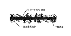
- FIG. 2 is a schematic view of the metal foil 10 with a coating layer in which the resin composition layers 11 and 12 that can be remelted are provided on both surfaces of the metal foil 10. As shown in the figure, free metal particles are dispersed in the coating layers 11 and 12. In FIG. 2, the composition layers 11 and 12 are provided on both surfaces of the metal foil 10, but if only one surface is satisfactory, it is not necessary to provide the composition layers on both surfaces.
- Second Embodiment A second embodiment for producing a metal foil with a coating layer of the present invention will be described with reference to a flowchart shown in FIG.
- Step 21 (Preparation of free metal particles) Metal particles made of copper, nickel, manganese, iron, chromium, tungsten, molybdenum, vanadium, and indium are prepared.
- the particle size of the metal particles is preferably in the range of 0.1 ⁇ m to 3.5 ⁇ m.
- One type or two or more types of metal particles are selected depending on the conductivity of the active material layer to be mixed.
- Step 22 An active material mixture is prepared by mixing an active material, a binder, and, if necessary, conductive carbon black or a thickener and a slurry.
- an active material mixture for example, polyimide is mixed as a binder.
- Step 23 (formulation)
- the free metal particles of Step 1 are mixed into the active material mixture prepared in Step 2 to impart conductivity to the active material layer.
- Step 24 (coating)
- the active material mixture blended in step 3 is applied to one side of a metal foil (copper foil, aluminum foil, etc.) 30 and coated.
- the coating can be performed by a general method such as a press method.
- FIG. 4 is a schematic view of a metal foil with a coating layer in which an active material layer 32 is provided on one side of the metal foil 30. As shown in the figure, free metal particles 34 are dispersed in a gap between the active materials 33 in the coating layer (active material layer) 32.
- the active material layer 32 is provided on one surface of the metal foil 30, but when it is necessary to provide the active material layer 32 on both surfaces, an active material layer is provided on both surfaces of the foil in the following steps.
- Step 25 The active material mixture of step 3 is applied and coated on the other surface of the metal foil (copper foil, aluminum foil, etc.).
- the coating can be performed by a general method such as a press method.
- surface or both surfaces by the above process can be manufactured.
- Step 31 Metal particles made of copper, nickel, manganese, iron, chromium, tungsten, molybdenum, vanadium, and indium are prepared.
- the particle size of the metal particles is preferably in the range of 0.1 ⁇ m to 3.5 ⁇ m.
- One type or a combination of two or more types of metal particles is selected depending on the conductivity of the resin composition to be mixed.
- Step 32 Preparation of remeltable resin composition
- a remeltable resin composition is prepared.
- a commercially available thermoplastic resin composition for example, vinylidene fluoride resin (hereinafter referred to as PVDF)
- a thermosetting resin composition for example, a thermosetting polyimide resin
- Step 33 (formulation)
- the metal composition selected in step 31 is mixed into the meltable resin composition selected in step 32 to create a resin composition imparted with conductivity.
- Step 34 the resin composition containing metal particles is coated on the surface of a metal foil (copper foil, aluminum foil, etc.).
- the coating can be performed by a general method such as a press method.
- a thermosetting polyimide resin is employed as the thermosetting resin composition, dissolved in a solvent with free metal particles added to the resin, and applied to the surface of the metal foil, and then the thermosetting polyimide resin.
- the solvent is evaporated so as to become a B-stage resin and dried to form a remeltable resin layer containing metal particles (B-stage resin) on the surface of the metal foil.
- Step 35 An active material mixture is prepared by mixing an active material, a binder, and, if necessary, conductive carbon black or a thickener and a slurry.
- an active material mixture for example, polyimide is mixed as a binder.
- Step 36 formation of active material layer
- An active material layer is formed with the active material mixture blended in step 35 on the resin composition layer (coating layer) formed in step 34.
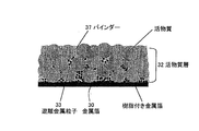
- FIG. 6 is a schematic view of a metal foil with a coating layer in which a resin composition layer is provided on one surface of a metal foil 30 and an active material layer 32 is provided on the surface of the composition layer. As shown in the figure, free metal particles 33 are dispersed in the composition layer, and a part of the free metal particles enters the active material layer 32 thereon.
- reference numeral 37 denotes a binder.
- the composition layer and the active material layer 32 are provided on one surface of the metal foil 30. However, when it is necessary to provide both surfaces, the composition layer and the active material layer are provided on both surfaces.
- Step 37 (Create electrode)
- the metal foil with an active material layer prepared in step 35 is formed for an electrode.
- Step 38 Battery creation
- the electrode created in step 36 is incorporated into the positive electrode or the negative electrode to complete the battery.
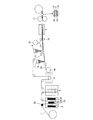
- Step 41 surface roughening process
- the metal foil 1 is guided to the surface roughening treatment tank 2, and metal particles are grown on the surface of the metal foil 1 by plating to form the roughened metal layer 3.
- the metal foil 1 is guided to the roughening treatment tank 2 through the feeding electrode 20 and passes between the plating electrodes 22, 24, and 26 arranged in the roughening treatment tank 2.
- the plating electrodes 22, 24, and 26 are arranged at three locations to roughen both surfaces of the metal foil 1.
- the electrode 26 is omitted. can do.
- the roughening process conditions will be described later.
- the roughened metal layer 3 is guided to the water washing tank 4 and washed with water.
- the metal foil washed with water is guided to the antirust treatment tank 5 and a rust preventive agent is applied to the surface of the roughened metal layer 3.
- a rust prevention process can be abbreviate
- Step 42 Formation of remeltable resin composition layer
- the resin composition is coated on the surface of the metal foil (copper foil, aluminum foil, etc.) on which the roughened layer is formed in step 2.
- the coating method can be performed by a general method such as a press method.
- the resin composition is melted in a solvent and roughened in step 41. The method of applying to will be described.
- the resin composition is dissolved in a solvent and filled in the container 6.
- the metal foil provided with the rust prevention layer is guided to the container 6 (filled with a resin composition dissolved in a solvent), and a solution made of the resin composition is applied to the surface.
- Step 43 drying process After applying the resin composition to the surface of the metal foil, the solvent is evaporated and dried by the solvent evaporation device 8.
- Step 44 The dried metal foil with a resin composition layer is wound on a winder 11.
- a remeltable resin layer containing metal particles on the surface of the metal foil as shown in FIG. Resin can be formed.
- FIG. 8 it demonstrates still in detail about the formation process of the remeltable resin composition layer of step 42.
- the roughening treatment layer formed by the plating method is preferably applied by roughening treatment by burnt plating.
- the roughened layer applied by burnt plating maintains an unhealthy state in which the roughened particles fall off (powder off).
- a metal foil is immersed and passed through a tank 6 of a solution in which, for example, vinylidene fluoride resin (hereinafter referred to as PVDF) is dissolved in a 1-methyl-2-pyrrolidone (NMD) solvent on the roughened surface.
- PVDF vinylidene fluoride resin
- NMD 1-methyl-2-pyrrolidone
- thermosetting polyimide resin is used as the remeltable resin composition
- the polyimide is dissolved in an appropriate solvent by adjusting the weight ratio, and the solution vessel 6 is roughened by the burnt plating as described above.
- the treated copper foil is immersed and passed through. Thereafter, the solvent is evaporated over a predetermined period of time so that the thermosetting polyimide resin becomes a B-stage resin, dried, and attached to the surface of the metal foil.
- the metal foil with a coating layer in which the roughened particles are mixed into the B-stage resin can be produced.
- the resin composition layer is applied and dried on the dendritic rough particle layer adhering in such a brittle state. Dendritic roughened particles are destroyed during application of the resin composition, during expansion / contraction during drying, or in subsequent steps, and the broken particles are dispersed in the resin composition layer as shown in FIG. It is taken in in the resin composition layer.
- Step 51 surface roughening process
- the metal foil 1 is guided to the surface roughening treatment tank 2, and metal particles are grown on the surface of the metal foil I by plating to form the roughened metal layer 3.
- the metal foil 1 is guided to the roughening treatment tank 2 through the feeding electrode 20 and passes between the plating electrodes 22, 24, and 26 arranged in the roughening treatment tank 2.
- plating electrodes 22, 24, and 26 are arranged at three locations for roughening both surfaces of the metal foil 1.
- the electrode 26 is omitted. can do.
- the roughening process conditions will be described later.
- the roughened metal layer 3 is guided to the water washing tank 4 and washed with water.
- the metal foil washed with water is guided to the antirust treatment tank 5 and a rust preventive agent is applied to the surface of the roughened metal layer 3.
- a rust prevention process can be abbreviate
- Step 52 active material mixture creation process
- An active material, a binder, and, if necessary, conductive carbon black or a thickener and a slurry are mixed to prepare an active material mixture 8, and the active material mixture 8 is supplied to the hoppers 6 and 7.
- Step 53 first active material layer forming step
- the surface of the metal foil subjected to the surface roughening treatment is rust-prevented with the rust-preventing treatment layer 5, and the active material mixture 8 is poured uniformly from the hopper 6 onto one surface thereof. 8 is dried to form an active material layer 31.
- Step 54 (second active material layer forming step) Next, the active material mixture 8 is poured uniformly from the hopper 7 onto the other surface and dried by the drying device 10 to form the active material layer 32.
- Step 55 drying / pressurizing process
- a metal foil with an active material layer having active material layers 31 and 32 formed on both sides is passed through a press 11 and heated and pressurized.
- the active material layers 31 and 32 are uniformly adhered to the surface of the metal foil, and are moved by being pressed against the roughened particles in the pressing step, as shown in FIG.
- Roughened metal particles 35 that are not fixed to the foil I are separated from the base metal foil 1 and taken into and dispersed in the active material layer 31 (32), so that the interface between the active material layer 31 (32) and the base metal foil 1 is dispersed.
- Improve conductivity In the figure, 33 is an active material, 37 is a binder and a conductive material to be added if necessary.
- the distribution of the roughened metal particles is characterized by being concentrated on the base metal foil side and decreasing toward the outermost surface of the active material layer.
- Step 56 Winding process
- the pressed and dried metal foil with the active material layer is taken up by the winder 12 and conveyed to the manufacturing process of the electrode (step 47) and battery (step 48) as the next process.
- Step 61 surface roughening process
- the metal foil 1 is guided to the surface roughening treatment tank 2, and metal particles are grown on the surface of the metal foil I by plating to form the roughened metal layer 3.
- the metal foil 1 is guided to the roughening treatment tank 2 through the feeding electrode 20 and passes between the plating electrodes 22, 24, and 26 arranged in the roughening treatment tank 2.
- plating electrodes 22, 24, and 26 are disposed at three locations for roughening both surfaces of the metal foil 1.
- the electrode 26 is omitted. can do. The roughening process conditions will be described later.
- the roughened metal layer 3 is guided to the water washing tank 4 and washed with water.
- the metal foil washed with water is guided to the antirust treatment tank 5 and a rust preventive agent is applied to the surface of the roughened metal layer 3.
- a rust prevention process can be abbreviate
- Step 62 active material mixture creation process
- An active material, a binder, and, if necessary, conductive carbon black or a thickener and a slurry are mixed to prepare an active material mixture 8, and the active material mixture 8 is supplied to the hoppers 6 and 7.
- Step 63 first active material layer forming step
- the surface of the metal foil subjected to the surface roughening treatment is subjected to a rust prevention treatment with the rust prevention treatment layer 5, and the active material mixture 8 is poured uniformly from one surface of the hopper 6 to form an active material layer 31.
- the surface of the active material layer 31 is supplied with a plastic film or release paper 13 from the film supply roll 15 (when it is not necessary to distinguish between the plastic film and the release paper, both are simply expressed as the film 13) and attached.
- Step 64 (second active material layer forming step)
- the active material mixture 8 is uniformly poured from the hopper 7 into the film 13 supplied from the supply roll 14 of the film 13, and the active material mixture 8 conveyed from the film 13 is applied to the other surface of the surface-roughened metal foil. Then, the active material layer 32 is formed.
- Step 65 drying / pressurizing process
- the metal foil with an active material layer having active material layers 31 and 32 formed on both sides is heated and pressurized through a dryer 9 and a press 11.
- the active material layers 31 and 32 are uniformly adhered to the surface of the metal foil, and some of the metal particles of the roughened metal layer 3 grown by the surface treatment in this pressing step are active material. Incorporated into the layer.
- Step 66 Winding process
- the pressed and dried metal foil with an active material layer is taken up by the winder 12 and conveyed to the electrode / battery manufacturing process, which is the next process.
- the film 13 is provided on the active material layer 32. Therefore, the active material layer 32 and the active material layer 32 are not in direct contact with each other when wound on the winder (for example, bobbin) 12, and the active material layer is not damaged by winding.
- the trouble at the time of battery assembly can be reduced by using the same thing as the separator used for the electrode of a lithium ion secondary battery, for example.
- it when it is not necessary to cover the active material layer surface with a film, it can be deleted after the active material layer drying step.
- Seventh Embodiment A seventh embodiment for manufacturing a metal foil with a coating layer according to the present invention will be described with reference to a flowchart shown in FIG. 13 and a manufacturing apparatus shown in FIG.
- Step 71 surface roughening process
- the metal foil 1 is guided to the surface roughening treatment tank 2, and metal particles are grown on the surface of the metal foil I by plating to form the roughened metal layer 3.
- the metal foil 1 is guided to the roughening treatment tank 2 through the feeding electrode 20 and passes between the plating electrodes 22, 24, 26 arranged in the roughening treatment tank 2.
- plating electrodes 22, 24, and 26 are disposed at three locations for roughening both surfaces of the metal foil 1.
- the electrode 26 is omitted. can do. The roughening process conditions will be described later.
- the roughened metal layer 3 is guided to the water washing tank 4 and washed with water.
- the metal foil washed with water is guided to the antirust treatment tank 5 and a rust preventive agent is applied to the surface of the roughened metal layer 3.
- a rust prevention process can be abbreviate
- Step 72 A remeltable resin composition is supplied to one side of the roughened metal foil.
- the remeltable resin composition a commercially available thermoplastic resin composition can be used. In the present embodiment, as described above, it is preferable to select a resin composition that can adhere to the active material layer provided on the resin composition layer. As shown in FIG. 13, a film 40 of a remeltable resin composition is supplied to one side of the metal foil 1, and both are attached by a pressure roll 41. If necessary, thermocompression bonding.
- Step 73 active material mixture creation process
- the active material, binder, conductive carbon black or thickener and slurry are mixed as necessary, and the active material mixture 8 is supplied to the hoppers 6 and 7.
- the active material mixture 8 is supplied to the hoppers 6 and 7.
- the active material 31 and the metal foil 1 are in close contact with the remeltable resin composition layer 40.
- polyimide is used as a binder to form a homogeneous slurry coating film. Is preferred.
- Step 74 (first active material layer forming step)
- the active material mixture 8 is uniformly poured from the hopper 6 into the metal foil whose one surface is coated with the remeltable resin composition 40, and the active material mixture 8 is dried by the drying device 9 to form the active material layer 31.
- Step 75 (second remeltable resin composition layer forming step)
- a remeltable resin composition film 42 is supplied to the other surface of the metal foil 1, and the both are pasted by the pressure roll 41. If necessary, thermocompression bonding.
- Step 76 (second active material layer forming step)
- the active material mixture 8 is uniformly poured from the hopper 7 onto the surface of the remeltable resin composition film 42, and is dried by the drying device 10 to form the active material layer 32.
- Step 77 drying / pressurizing process
- a metal foil with an active material layer having active material layers 31 and 32 formed on both sides is passed through a press 11 and heated and pressurized.
- the active material layers 31 and 32 are uniformly adhered to the surface of the metal foil via the remeltable resin composition layers 40 and 42.
- a part of the metal particles of the roughened metal layer 3 grown by the surface treatment is taken into the resin composition layer that can be remelted in the attaching step and the heating / pressurizing step.
- the roughened metal particles 35 move away from the surface of the metal foil in a remeltable resin composition layer sticking step and an active material layer pressurizing step, and can be remelted.
- the conductivity at the interface between the active material layer 31 (32) and the metal foil 1 is improved.
- 33 is an active material
- 37 is a binder and a conductive material to be added if necessary.
- the distribution of the roughened metal particles is characterized by being concentrated on the metal foil side and decreasing toward the active material layer side.
- Step 78 Winding process
- the pressed and dried metal foil with an active material layer is taken up by the winder 12 and conveyed to the electrode / battery manufacturing process, which is the next process.
- the labor at the time of battery assembly can be reduced.
- Step 81 surface roughening process
- the metal foil 1 is guided to the surface roughening treatment tank 2, and metal particles are grown on the surface of the metal foil I by plating to form the roughened metal layer 3.
- the metal foil 1 is guided to the roughening treatment tank 2 through the feeding electrode 20 and passes between the plating electrodes 22, 24, 26 arranged in the roughening treatment tank 2.
- plating electrodes 22, 24, and 26 are disposed at three locations for roughening both surfaces of the metal foil 1.
- the electrode 26 is omitted. can do. The roughening process conditions will be described later.
- the roughened metal layer 3 is guided to the water washing tank 4 and washed with water.
- the metal foil washed with water is guided to the antirust treatment tank 5 and a rust preventive agent is applied to the surface of the roughened metal layer 3.
- a rust prevention process can be abbreviate
- Step 82 (Remeltable resin composition layer forming step)
- a remeltable resin composition layer 40 is supplied to both surfaces of the roughened metal foil 1.
- the remeltable resin composition a commercially available thermoplastic resin composition can be used.
- a remeltable resin composition film 40 is supplied to both surfaces of the metal foil 1, and both are pasted with a pressure-bonding roll 41. If necessary, thermocompression bonding.
- the labor at the time of battery assembly can be reduced.
- Step 83 active material mixture creation process
- the active material, binder, conductive carbon black or thickener and slurry are mixed as necessary, and the active material mixture 8 is supplied to the hoppers 6 and 7.
- the active material mixture 8 is supplied to the hoppers 6 and 7.
- the active material 31 and the metal foil 1 are in close contact with the remeltable resin composition layer 40.
- polyimide is used as a binder to form a homogeneous slurry coating film. Is preferred.
- Step 84 (first active material layer forming step)
- the active material mixture 8 is poured uniformly from the hopper 6 onto one surface of the metal foil on which the remeltable resin composition layer is formed, the active material layer 31 is formed, and a film is supplied to the surface of the active material layer 31
- the film 13 is supplied from the roll 15 and attached.
- Step 85 (second active material layer forming step)
- the active material mixture 8 is uniformly poured from the hopper 7 into the film 13 supplied from the supply roll 14 of the film 13, and the active material mixture 8 conveyed from the film 13 is coated with a remeltable resin composition layer
- the active material layer 32 is formed by supplying the other surface of the foil.
- Step 86 drying / pressurizing process
- a metal foil with an active material layer having active material layers 31 and 32 formed on both sides is passed through a press 11 and heated and pressurized.
- the active material layers 31 and 32 are uniformly adhered to the surface of the metal foil via the remeltable resin composition layers 40 and 42.
- a part of the metal particles of the roughened metal layer 3 grown by the surface treatment is taken into the resin composition layer that can be remelted in the attaching step and the heating / pressurizing step.
- Step 87 winding process
- the pressed and dried metal foil with an active material layer is taken up by the winder 12 and conveyed to the electrode / battery manufacturing process, which is the next process.
- the film 13 is provided on the active material layer 32. Therefore, the active material layer 32 and the active material layer 32 are not in direct contact with each other when wound on the winder (for example, bobbin) 12, and the active material layer is not damaged by winding. Moreover, the trouble at the time of battery assembly can be reduced by using the same thing as the separator used for the electrode of a lithium ion secondary battery. In addition, when it is not necessary to cover the active material layer surface with a film, it can be deleted after the active material layer drying step.
- Step 88 The metal foil having the prepared active material layer is finished into a battery electrode.
- Step 89 The battery is completed by incorporating the above electrode into the battery.
- the metal foil provided with the active material layer as the coating layer can be directly used as a battery electrode because the active material layer is formed on the surface of the metal foil. Therefore, a metal suitable for the current collector constituting the battery electrode is selected as the metal foil.
- a metal suitable for the current collector constituting the battery electrode is selected as the metal foil.
- an aluminum foil is selected as the positive electrode of the lithium ion secondary battery
- a copper foil is selected as the negative electrode.
- an electrolytic copper foil may be selected and described as the metal foil, but the electrolytic copper foil can be replaced with a rolled copper foil.
- Lithium ion secondary that does not cause wrinkles in the current collector, does not cause breakage of the current collector, has high adhesion between the active material and the current collector metal foil, and can maintain stable secondary battery characteristics for a long time
- any metal foil that can be selected as a battery electrode metal foil with an active material layer
- the roughening process layer is provided by the burnt plating method which sends the electric current more than the limiting current density in an electrolytic bath on the surface of metal foil, for example, copper foil, in the surface roughening process.
- the roughening layer formed by the roughening process by the burnt plating method is formed in a dendritic shape, and the tip of the dendritic roughening layer is formed brittle.
- a roughened layer is formed on the surface of the base metal foil having a surface roughness Rz of 0.5 to 5 ⁇ m by a burnt plating method.
- the particle size is preferably grown to 0.1 ⁇ m to 3 ⁇ m.
- the difference in roughness Rz between the front and back surfaces of the base metal foil is 2.5 ⁇ m or less.
- the cathode electrolytic plating It is preferable to apply by the burn plating method.
- the plating method is not limited to the burn plating method as long as the metal particles grown by the surface treatment can be grown in the above preferred range.
- the surface of the metal foil is subjected to a surface roughening treatment, and the grown tip portion of the particle roughening treatment layer is a step of providing an active material layer on the surface of the roughening treatment layer.
- any method can be adopted as long as it is a plating method provided with the strength of dropping and dispersing.
- a metal foil having a smooth surface is selected, and a current is passed beyond the limit current density in the electrolytic bath, so that the particle size is 0.1 ⁇ m to 3 ⁇ m.
- a dendritic roughening treatment layer of .5 ⁇ m is formed so that the surface roughness Rz of the roughening treatment layer is 0.5 to 5 ⁇ m and the difference in surface roughness Rz between the front and back surfaces is 2.5 ⁇ m or less. Is preferred.
- the crystal structure of the cross section is preferably composed of fine granular crystals. This is because when the crystal structure of the copper foil is a granular crystal, the difference in roughness between the front and back surfaces can be reduced, and the difference in the roughness Rz value after applying the roughened particles can be further reduced. If the copper foil has a columnar crystal structure, the difference between the front and back roughness becomes large, and it becomes difficult to eliminate the difference even after the roughening treatment.
- the metal foil for a lithium ion secondary battery electrode of the present invention has a particle size of 0 by burnt plating (hereinafter sometimes simply referred to as burnt plating) in which a current equal to or higher than the limiting current density in the electrolytic bath is applied to the front and back surfaces of the base metal foil.
- burnt plating a current equal to or higher than the limiting current density in the electrolytic bath is applied to the front and back surfaces of the base metal foil.
- a layer of roughened particles of 1 ⁇ m to 3 ⁇ m is provided, the surface roughness Rz of each surface is 0.5 to 5 ⁇ m, and the difference between the front and back surface roughness Rz is 2.5 ⁇ m or less.
- the roughening particles are applied to the surface of the base copper foil, thereby improving and improving the adhesion with the active material and changing the volume accompanying expansion and contraction inside the battery. Stress relaxation can be absorbed by the void space obtained by roughening.
- the material for forming the roughened layer is Cu roughened particles, or particles containing Cu, the main component of which is Fe, Ni, Cr, W, Mo, V, or a plurality thereof. It is preferable that By forming a roughened layer with roughened particles comprising Cu or a copper alloy composition containing Cu as a main component, the adhesion between the roughened particles and the base copper foil is improved, and the particle size of the roughened particles is reduced. By appropriately controlling the current density (limit current density) of the burnt plating, it becomes easy to arbitrarily adjust the surface roughness Rz value.
- the copper foil as the metal foil may be an electrolytic copper foil or a rolled copper foil, the surface roughness is about 0.8 to 2.0 ⁇ m, and the grain boundary structure at room temperature is from a granular crystal having a particle size of 5 ⁇ m or less.
- the tensile strength (TS) is 300 MPa or more at room temperature
- the elongation (E) is 3.5% or more
- the copper capable of maintaining the tensile strength after 150 ° C. ⁇ 15 hours is 250 MPa or more.
- a foil is particularly preferred.
- the tensile strength (T.S) of the metal foil decreases and the elongation (E) tends to increase.
- the strength (TS) of the current collector (metal foil) is low, the battery will expand and contract regardless of the roughening treatment.
- the metal foil cannot be absorbed and cracks occur in the metal foil.
- the tensile strength is 300 MPa or more and the elongation is 3.5% or more.
- the crystal structure grain size is preferably 5 ⁇ m or less.
- the drying conditions at this time are generally about 100 to 200 ° C. and about 5 to 20 hours. If the current collector (metal foil) is plastically deformed or softened at this time, the foil breaks and breaks during charging and discharging for the reasons described above, so the strength (hardness) of the foil after the drying process Is also an important component of physical properties.
- the additive composition concentration in the electrolytic solution during the electrolytic foil production is changed to MPS (3-mercapto 1-
- a foil production method is recommended in which 3 to 10 ppm of sodium propanesulfonate), 15 to 20 ppm of HEC (hydroxyethyl cellulose / polymer polysaccharide), and 30 to 70 ppm of animal glue are set.
- the surface area ratio after the roughening particle application treatment is preferably 2.5 to 5 times.
- the surface area ratio is measured by using KEYENCE VK-8500 to measure the area of 2500 ⁇ m 2 (50 ⁇ m ⁇ 50 ⁇ m) on the surface of the metal foil. Based on this value, the base metal foil (before roughening) and the area after roughening Is expressed as a ratio. That is, when the surface area ratio is 1, it means that the surface area does not change before and after the roughening treatment. When the area after the roughening treatment is 5000 ⁇ m 2 , the surface area ratio is doubled.
- the tensile strength (TS) and elongation (E) of the present invention are values measured by a method defined in Japanese Industrial Standard (JISK6251).
- the surface roughness Rz is a ten-point average roughness and an arithmetic surface roughness defined in Japanese Industrial Standards (JIS B0601-1994), and is a value measured with a general-purpose surface roughness meter.
- the surface roughness Rz of the front and back surfaces of the base metal foil is preferably a smooth surface of 0.5 to 5 ⁇ m.
- the burnt plating method is a plating method in which a current equal to or higher than the limiting current density in the electrolytic bath is passed, and is suitable as a roughening treatment method for imparting uniform unevenness to the surface of a smooth base metal foil. The front and back surfaces of the metal foil are roughened by this burnt plating method.
- Patent Document 5 Japanese Patent Publication No. 53-393766
- Patent Document 5 after forming a grainy copper plating layer by “yake plating”, “capsule plating” is performed on the grainy copper plating layer so as not to impair the uneven shape, This is a technique for forming a smooth, rough copper-like copper layer that does not drop off (does not fall off) granular copper by forming a smooth plating layer.
- the present invention does not implement the capsule plating technique pointed out in Patent Document 5, and is in a state of roughening treatment by burnt plating, that is, an unhealthy state in which the roughened particles fall off (powder off). It is characterized by holding.
- the reason why the process is stopped only by the burn plating is as follows.
- burnt plating is applied to the surface of the base metal foil, dendritic roughened particles uniformly adhere to the front and back surfaces of the foil.
- the roughening particles extending in a dendritic shape are attached to the front and back surfaces of the foil in a brittle state where the tip is easily broken and dropped off.
- an active material is apply
- the burnt plating layer does not become an obstacle in the process of creating the active material layer.
- the active material composition is applied, dried, and subjected to a heat and pressure press process, an unnecessary solvent that has formed the active material in a slurry state is volatilized and the active material is solidified.
- the dendritic particles fall off, but the dropped coarse particles are taken into the active material layer, and the portion where the dendritic active material does not fall off constitutes the roughening (unevenness) of the copper foil surface.
- the active material layer is firmly bonded to the front and back of the copper foil with a binder.
- the active material layer is formed in a state where the tip portion extended in a dendritic state enters the active material layer and the copper particles are liberated in the active material.
- the base part is formed with a roughened shape on the surface of the copper foil along the shape of the active material, not only improving the adhesion between the active material and the copper foil, but also the internal residual stress compared to the conventional roughened copper foil Therefore, the conductivity is increased and the battery negative electrode with less heat generation is obtained.
- the active material composition is exposed to a high temperature of 300 ° C. during the application, drying, heating, and pressure pressing processes, the roughened particles in the base portion are sintered and fixed to the copper foil surface. .
- the roughening tank 2 is replaced with a conductive aqueous solution containing a polymer dispersion medium, and copper is applied to the surface of the untreated copper foil.
- a treatment for depositing nanoparticles can also be handled.
- the copper particles become smaller and later formed into the negative electrode of the battery, the copper nanoparticles can come into contact with the active material without any gaps, so that the conductivity with the negative electrode current collector can be further improved.
- capsule plating is not performed after burnt plating as in the past.
- the roughened particles are not fixed to the base metal foil, and the active material is pressed against the roughened particles by the pressure of the heating / pressurizing step (press) and moved, so that the roughened particles become active. It can move in a state where a part is taken into the active material layer along the shape of the material, and the contact area between the roughened particles and the active material is maximized.
- the roughened particles are fixed to the base metal foil.
- the base metal foil is also broken.
- an active material that occludes lithium by alloying with a material that occludes and releases lithium can be selected.
- silicon, germanium, tin, lead, zinc, magnesium, sodium, aluminum, potassium, indium and the like are known.
- silicon or tin is preferred as a negative electrode active material in recent years because it is preferred because of its high theoretical capacity and ease of handling.
- the negative electrode active material layer of the lithium ion secondary battery is preferably an active material layer containing silicon or tin as a main component in addition to graphite, and particularly preferably a layer containing silicon as a main component.
- the active material layer is preferably an amorphous layer or a microcrystalline layer.
- the active material layer is preferably an amorphous silicon layer or a microcrystalline silicon layer.
- the current collector is thin, and it is preferable that the secondary battery is lightweight and light in design.
- the metal foil copper foil is selected for the negative electrode current collector, and aluminum is selected for the positive electrode current collector.
- the active material layer is formed by coating and depositing on one surface or front and back surfaces of the current collector. When the active material layer is formed on the front and back of the current collector, the surface roughness Rz on both sides of the current collector is in the range of 0.5 to 5 ⁇ m, and the difference between the Rz values on the front and back is 2.5 ⁇ m or less. It is preferable.
- the thickness of the current collector is preferably about 8 ⁇ m for a thin one and about 20 ⁇ m for a thick one. If the thickness is 8 ⁇ m or less, the strength of the foil (as a current collector) cannot be maintained, and crack fracture occurs when the active material expands and contracts. If the thickness exceeds 20 ⁇ m, the battery characteristics can be satisfied, but the battery itself is large and heavy.
- the Rz values on the front and back surfaces are in the range of 0.5 to 5 ⁇ m.
- the Rz value is lower than the lower limit, the adhesion due to the anchor effect with the active material layer becomes poor, and when the Rz value is higher than the upper limit value, the active material does not uniformly enter the concaves corresponding to the roughened irregularities, and the current collector and the active material This is not preferable because the adhesion of the layer becomes insufficient.
- the surface roughness is large between the front and back surfaces, the thickness of the active material is different on both sides in the active material coating process, which causes a problem in battery electrode characteristics. Therefore, the difference in the roughness Rz between the front and back sides is set to 2.5 ⁇ m or less. That is, when the difference in roughness Rz between the front and back surfaces is 2.5 ⁇ m or more, the thickness of the active material is different on both sides in the active material coating process, and sufficient battery electrode characteristics cannot be obtained.
- the lithium ion secondary battery of the present invention comprises a negative electrode on which an active material layer mainly composed of graphite, silicon, or tin is applied and deposited as an active material for a lithium ion secondary battery; A positive electrode using a substance to be released, a nonaqueous electrolyte, and a separator are provided.
- the non-aqueous electrolyte used in the lithium ion secondary battery of the present invention is an electrolyte in which a solute is dissolved in a solvent
- the solvent of the non-aqueous electrolyte is not particularly limited as long as it is a solvent used in a lithium ion secondary battery.
- examples include cyclic carbonates such as ethylene carbonate, propylene carbonate, butylene carbonate, and vinylene carbonate, and chain carbonates such as dimethyl carbonate, diethyl carbonate, and methyl ethyl carbonate.
- a mixed solvent of cyclic carbonate and chain carbonate is used. Is used.
- a mixed solvent of a cyclic carbonate and an ether solvent such as 1,2-dimethoxyethane or 1,2-diethoxyethane, or a chain ester such as ⁇ -butyrolactone, sulfolane, or methyl acetate may be used.
- the solute of the nonaqueous electrolyte is not particularly limited as long as it is a solute used for a lithium ion secondary battery.
- LiPF 6 , LiBF 4 , LiCF 3 SO 3 , LiN (CF 3 SO 2 ) 2 , LiN (C 2 F 5 SO 2 ) 2 , LiN (CF 3 SO 2 ) (C 4 F 9 SO 2 ), LiC (CF 3 SO 2 ) 3 , LiC (C 2 F 5 SO 2 ) 3 , LiAsF 6 , LiClO 4 Examples include Li 2 B 10 Cl 10 and Li 2 B 12 Cl 12 .
- a gel polymer electrolyte obtained by impregnating a polymer electrolyte such as polyethylene oxide, polyacrylonitrile, or polyvinylidene fluoride with an electrolytic solution, or an inorganic solid electrolyte such as LiI or Li 3 N can be used.
- a polymer electrolyte such as polyethylene oxide, polyacrylonitrile, or polyvinylidene fluoride
- an electrolytic solution or an inorganic solid electrolyte such as LiI or Li 3 N
- the electrolyte of the lithium ion secondary battery of the present invention can be used without restriction unless it is decomposed by the voltage at the time of charge / discharge or storage.
- the positive electrode active material used for the positive electrode and LiCoO 2, LiNiO 2, LiMn 2 O4, LiMnO 2, LiCo 0.5 Ni 0.5 O 2, LiNi 0.7 Co 0.2 Mn 0.1 lithium-containing transition metal oxides such as O 2, MnO
- the metal oxide that does not contain lithium such as 2 can be used without limitation as long as the material can accept and release lithium ions in the battery.
- conductive metal fine particles dropped roughening treatment layer
- the active material layer in a drying / pressurizing process and the like, and appropriately dispersed in the active material layer.
- the conductivity of the active material layer is improved, and the negative electrode current collector can be prevented from wrinkling and cracking during charging / discharging, and the energy density per volume of the lithium ion secondary battery is increased and stable for a long time.
- a lithium ion secondary battery that maintains the performance can be provided.
- a film is interposed to protect the surface of the active material layer overlapped.
- a film is present on one surface, when the metal foil with an active material layer is wound up, an accident in which the active material layers are in contact with each other and possibly damaged can be prevented.
- this metal foil with an active material layer is used as an electrode of a secondary battery, if the film is made of the same material as the battery electrode separator, the separator can be shared as an electrode, and there is no need to remove it.
- the battery separator is an important material that separates the positive electrode and the negative electrode in the battery and retains the electrolytic solution to ensure the ionic conductivity between the positive electrode and the negative electrode.
- microporous membranes made of polyethylene (ultra-high molecular weight PE) or polypropylene (PP) are used for lithium ion batteries.
- PP / PE / PP There are three types of layer structure, PP / PE / PP.
- TG glass transition point
- polyethylene ultra high molecular weight PE
- Examples 1 and 4 and Comparative Example 1 copper foil is used as the metal foil.
- An electrolytic solution for foil production was prepared by adding MPS, HEC and chloride ions having the composition shown in Table 1 as additives to the acidic copper electrolytic bath.
- MPS is sodium 3-mercapto-1-propanesulfonate
- HEC high molecular polysaccharide
- glue is a low molecular weight glue having a molecular weight of 3000.
- the chloride ion concentration was adjusted to 30 ppm, the chloride ion concentration is appropriately changed depending on the electrolysis conditions, and is not limited to this concentration.
- an electrolytic copper foil having a thickness of 10 ⁇ m was prepared under the electrolysis conditions (current density, liquid temperature) shown in Table 1.
- Table 2 shows the surface roughness Rz and mechanical properties of the electrolytic copper foil that was made.
- each measured value shown in Table 2 is a value measured as follows. [Measurement of foil thickness, tensile strength (TS), elongation (E)] These are actual values measured with a micrometer, and tensile strength (TS) and elongation (E) are values measured using a tensile tester (type 1122 manufactured by Instron).
- the surface roughness Rz is a value measured with a stylus type surface roughness meter (SE-3C type manufactured by Kosaka Laboratory).
- the rust prevention treatment tank 5 may be spread and rust prevention treatment may be performed so that the copper foil is not discolored and lightly dried before slurry application.
- Table 3 shows the characteristic values after applying the roughened particles.
- Table 3 shows the characteristic values after applying the roughening particles by the burnt plating.
- Example 4 the feed roll shown in FIG. 8 was used as a cathode and the feed electrode 20 was used as an anode, and roughening was performed under the following conditions.
- Surface roughening conditions In normal electrolytic copper plating solution (copper sulfate 40-250 g / l, sulfuric acid 30-210 g / l, hydrochloric acid 10-80 ppm, additives such as brightener specified by the manufacturer) The temperature was kept at 18 to 32 ° C., and the current density was 1 A / dm 2 or more. When the current density was lower than 1 A / dm 2, it was found that the amount of copper plating was too small and almost no copper fine particles were deposited. Therefore, Example 4 was performed at 8 A / dm 2 . If the current density is increased, a large amount of copper fine particles are precipitated. Therefore, if necessary, the amount of copper fine particles deposited may be controlled by controlling the current density.
- Examples 2 and 3 In Examples 2 and 3, rolled copper foil was used, and the same surface treatment as in Example 1 was performed on the copper foil.
- Example 2 and Comparative Example 2 In this example, a low roughness rolled copper foil (Tough Bitch) manufactured by Nippon Foil Co., Ltd. was used.
- Example 3 In this example, a copper alloy foil (C14410) containing tin (0.15 wt%) manufactured by Nippon Foil Co., Ltd. was used.
- Example 4 In Example 4, the same electrolytic copper foil as used in Example 1 was used.
- the feeding roll 0 was a cathode, the feeding electrode 0 was an anode, and copper fine particles (0.1 ⁇ m) were used under the same surface roughening treatment conditions as in Example 1. ⁇ 3.5 ⁇ m) is produced on the foil surface and then washed in the treatment tank 4 with water.
- the tank for water washing shows one tank in FIG. 2, you may increase the tank for water washing as needed.
- a rust prevention treatment tank 5 may be provided to prevent the copper foil from discoloring in a subsequent drying step, and the rust prevention treatment may be performed and lightly dried before slurry application.
- the characteristic values after the application of the roughened particles are also shown in Table 3.
- Active Material Granulation Silicon was employed as the active material, and silicon (SiO), acetylene black, PVDF (polyvinylidene fluoride), and NMP (N-methyl-2-pyrrolidone) were mixed to form a slurry. Formation of active material layer The active material in the form of a slurry was used as a current collector for the copper foils of the examples and comparative examples, and coated on the current collector, heated and dried, and heated and pressed to form a silicon-based deposited layer. A copper foil with an active material layer was prepared as (active material layer). The active material mixture was adjusted to a suitable slurry viscosity with a demonstrable solvent so that it could be easily applied by a curtain coater. Moreover, although the method of apply
- a thickener or a conductive aid for adjusting the viscosity is added and kneaded as necessary, with the active material and binder as main components.
- the kneaded active material mixture is applied to the surface of the metal foil on which the metal particles are deposited, and after drying, the metal particles and the active material are in strong contact with each other by a hot roll press. As a result, the contact resistance between the active material layer and the current collector (metal foil) can be reduced.
- the contact area with the metal foil can be increased to the maximum as compared with the copper foil subjected to normal cup cell plating, and can contribute to cycle characteristics as a battery.
- the assembly and evaluation of the negative electrode current collector were performed under the following conditions.
- a three-electrode beaker cell was produced in a glove box under an argon gas atmosphere using the produced negative electrode current collector as an electrode.
- the beaker cell was configured by immersing a counter electrode (positive electrode), a working electrode (negative electrode), and a reference electrode in an electrolytic solution placed in a glass container.
- As the electrolytic solution an electrolytic solution in which 1 mol / liter of LiPF 6 was dissolved in a solvent in which ethylene carbonate and diethyl carbonate were mixed at a volume ratio of 3: 7 was used. Lithium metal was used as the counter electrode and the reference electrode.
- Example 2 a rolled copper foil is used as the base copper foil, the same roughening treatment as that of the electrolytic copper foil in Example 1 is performed, and the roughened rolled copper foil is used as a current collector.
- the battery was assembled and the battery characteristics were evaluated. The results are shown in Table 3 together with Example 1.
- Comparative Example 1 used the same untreated copper foil as Example 1, but the difference in roughness Rz value between both surfaces after the roughening treatment was large, and thus the discharge capacity retention after 100 cycles of charge / discharge efficiency was high. It became unsatisfactory. Moreover, in the comparative example 1, the crack fracture
- the present invention it is possible to increase the energy density per volume of the lithium ion secondary battery, to suppress the occurrence of deformation such as wrinkles and crack fracture of the current collector during charging and discharging, It is possible to provide a lithium ion secondary battery that can be downsized with a long lifetime in which the capacity does not decrease even when the discharge cycle is repeated.
Landscapes
- Chemical & Material Sciences (AREA)
- Engineering & Computer Science (AREA)
- Chemical Kinetics & Catalysis (AREA)
- Electrochemistry (AREA)
- Materials Engineering (AREA)
- Organic Chemistry (AREA)
- Metallurgy (AREA)
- Crystallography & Structural Chemistry (AREA)
- General Chemical & Material Sciences (AREA)
- Manufacturing & Machinery (AREA)
- Cell Electrode Carriers And Collectors (AREA)
- Battery Electrode And Active Subsutance (AREA)
- Electroplating Methods And Accessories (AREA)
Abstract
Description
また本発明は前記被覆層付き金属箔を用いた二次電池用電極、該電極を使用したリチウムイオン二次電池に関するものである。 The present invention relates to a metal foil with a coating layer that is particularly excellent as an electrode for a lithium ion secondary battery.
Moreover, this invention relates to the electrode for secondary batteries using the said metal foil with a coating layer, and the lithium ion secondary battery using this electrode.
該製造方法で製箔された電解銅箔(集電体)は、表裏に活物質として黒鉛粒子が結着剤と共に塗工され、さらに加熱加圧プレスされて活物質層付き銅箔とされ、リチウムイオン二次電池用負極電極とされている。 An electrolytic copper foil having a small difference in surface roughness between the front and back surfaces is produced by appropriately selecting a water-soluble polymer substance, a surfactant, an organic sulfur-based compound, chlorine ions, and the like and adding a trace amount. A typical known technique discloses a method for producing an electrolytic copper foil in which a compound having a mercapto group, a chloride ion, a low molecular weight glue having a molecular weight of 10,000 or less, and a high molecular weight polysaccharide are added to an electrolytic solution. (See Patent Document 2).
The electrolytic copper foil (current collector) produced by the production method is coated with graphite particles as an active material on the front and back, and further heated and pressed to form a copper foil with an active material layer, The negative electrode for a lithium ion secondary battery is used.
体積当たりのエネルギー密度(充放電容量)を向上させようとすると、集電体の伸縮に対して余裕がなくなるので、集電体が係る内部応力に耐えられずに破断し、安定した電池特性を維持することができなくなる、との課題がある。 When an electrode made of a metal foil with an active material layer having a large expansion and contraction is housed in a battery and repeated charging and discharging a number of times, the current collector (metal foil) expands and contracts in the same manner, so that wrinkles are generated inside. In order to allow wrinkles, it is necessary to provide a design with a sufficient volume occupied by the electrodes in the battery, but on the other hand, the battery has a problem in that the energy density per unit volume (charge / discharge capacity) decreases. .
When trying to improve the energy density per unit volume (charge / discharge capacity), there is no room for the expansion and contraction of the current collector, so the current collector breaks without being able to withstand the internal stress and stable battery characteristics are achieved. There is a problem that it cannot be maintained.
また集電体に破断亀裂が発生すると長時間安定した電池性能を維持できないばかりか充放電特性(サイクル特性)を低下させる。 When a metal foil with an active material layer coated with an active material mainly composed of silicon, germanium, or tin is used as an electrode instead of graphite for an electrode for a lithium ion secondary battery, a charge / discharge reaction occurs. The volume of the active material layer expands and contracts, and a large stress acts on the current collector (metal foil), which may cause problems such as wrinkles on the current collector. Furthermore, when charging / discharging is repeated many times, there is a problem that the current collector rarely breaks. When physical deformation such as wrinkles occurs in the current collector, the volume occupied by the electrode in the battery slightly increases, and as a result, the energy density per volume decreases.
In addition, when a fracture crack occurs in the current collector, stable battery performance cannot be maintained for a long time, and charge / discharge characteristics (cycle characteristics) are deteriorated.
また、前記被覆層は遊離金属粒子が含まれる活物質層であることが好ましい。 The coating layer is preferably a remeltable resin composition layer containing free metal particles.
The covering layer is preferably an active material layer containing free metal particles.
また、前記粗化処理層上に設けられる被覆層は活物質層であることが好ましい。
また、前記粗化処理層上に設けられる被覆層は再溶融可能な樹脂組成物層上に活物質層が設けられた層であることが好ましい。 The coating layer provided on the roughening treatment layer is preferably a resin composition layer that can be remelted.
Moreover, it is preferable that the coating layer provided on the said roughening process layer is an active material layer.
Moreover, it is preferable that the coating layer provided on the roughening treatment layer is a layer in which an active material layer is provided on a remeltable resin composition layer.
また、前記被覆層が活物質層であることが好ましい。
また、前記被覆層は再溶融が可能な樹脂組成物層であり、該樹脂組成物上に活物質層が設けられていることが好ましい。 The coating layer is preferably a resin composition layer that can be remelted.
Moreover, it is preferable that the said coating layer is an active material layer.
Moreover, it is preferable that the said coating layer is a resin composition layer which can be remelted, and the active material layer is provided on this resin composition.
また本発明の金属箔を集電体とて使用した場合、充放電時に生じる活物質の膨張収縮に対してシワ等の発生を抑制することができ、リチウムイオン二次電池の体積当りのエネルギー密度を高めることができる。また集電体が応力破断せず、活物質と集電体との密着性が高いために、長時間安定した出力性能を有するリチウムイオン二次電池電極の集電体用金属箔を提供することができる。 According to the metal foil for a current collector of a lithium ion secondary battery electrode of the present invention, when the foil is used as a current collector, the metal constituting the roughening treatment layer is mixed into the active material layer, so that it is conductive. Improves the energy density per volume of the lithium ion secondary battery.
In addition, when the metal foil of the present invention is used as a current collector, the generation of wrinkles and the like can be suppressed against the expansion and contraction of the active material that occurs during charging and discharging, and the energy density per volume of the lithium ion secondary battery Can be increased. Further, to provide a metal foil for a current collector of a lithium ion secondary battery electrode having stable output performance for a long time because the current collector is not stress-ruptured and the adhesiveness between the active material and the current collector is high. Can do.
本発明の被覆層付き金属箔を製造する第一実施形態につき図1に示すフローチャートを参照して説明する。
ステップ1(遊離金属粒子の準備)
銅、ニッケル、マンガン、鉄、クロム、タングステン、モリブデン、バナジウム、インジウムからなる金属粒子を準備する。金属粒子の粒径は0.1μm~3.5μmの範囲のものが好ましい。金属粒子は混入する下記樹脂組成物の導電率により1種類または2種類以上の組合せを選択する。 1st embodiment It demonstrates with reference to the flowchart shown in FIG. 1 about 1st embodiment which manufactures the metal foil with a coating layer of this invention.
Step 1 (Preparation of free metal particles)
Metal particles made of copper, nickel, manganese, iron, chromium, tungsten, molybdenum, vanadium, and indium are prepared. The particle size of the metal particles is preferably in the range of 0.1 μm to 3.5 μm. One type or a combination of two or more types of metal particles is selected depending on the conductivity of the resin composition to be mixed.
再溶融可能な樹脂組成物を準備する。再溶融可能な樹脂組成物としては一般に市販されている熱可塑性樹脂組成物〔一例としてフッ化ビニリデン樹脂(以下PVDF)〕、熱硬化樹脂組成物(一例として熱硬化性ポリイミド樹脂)を使用できる。
なお、本実施形態としては樹脂組成物層上に設ける下記活物質層と接着可能な樹脂組成物を選択することが好ましい。 Step 2 (Preparation of remeltable resin composition)
A remeltable resin composition is prepared. As the remeltable resin composition, commercially available thermoplastic resin compositions [for example, vinylidene fluoride resin (hereinafter PVDF)] and thermosetting resin compositions (for example, thermosetting polyimide resin) can be used.
In addition, as this embodiment, it is preferable to select the resin composition which can be adhere | attached with the following active material layer provided on a resin composition layer.
ステップ2で選定した再溶融可能な樹脂組成物にステップ1で選定した遊離金属粒子を混入し、導電性を付与した樹脂組成物を作成する。 Step 3 (Preparation of conductive resin composition)
The free metal particles selected in
金属箔(銅箔、アルミニウム箔等)の表面にステップ3で金属粒子を配合した樹脂組成物を被覆する。被覆方法はプレスによる方法等、一般的な方法で被覆することができる。
具体的に、熱硬化性樹脂組成物として熱硬化性ポリイミド樹脂を採用し、該樹脂に遊離金属粒子を添加した状態で溶媒に溶解して金属箔表面に塗布し、その後、熱硬化性ポリイミド樹脂をBステージレジンとなるように、溶媒を蒸散させ、乾燥して、金属箔の表面に遊離金属粒子を含有した再溶融可能な樹脂層を(Bステージレジン)形成する。
あるいは遊離金属粒子を含有する樹脂組成物を板状に整形し、金属箔表面にプレス等で張り合わせて被覆層付き金属箔を作成する。
以上の工程で遊離金属粒子を含有する再溶融可能な樹脂組成物層(被覆層)を有する金属箔を製造することができる。
図2は金属箔10の両表面に再溶融可能な樹脂組成物層11,12を設けた被覆層付き金属箔10の模式図である。図示するように被覆層11,12内には遊離金属粒子が分散されている。
なお、図2では金属箔10の両面に組成物層11,12を設けているが、片方の表面のみで満足できる場合は両方の表面に組成物層を設ける必要はない。 Step 4 (Coating)
In
Specifically, a thermosetting polyimide resin is employed as the thermosetting resin composition, dissolved in a solvent with free metal particles added to the resin, and applied to the surface of the metal foil, and then the thermosetting polyimide resin. The solvent is evaporated so as to become a B-stage resin and dried to form a remeltable resin layer containing free metal particles (B-stage resin) on the surface of the metal foil.
Alternatively, a resin composition containing free metal particles is shaped into a plate shape and pasted on the surface of the metal foil with a press or the like to form a metal foil with a coating layer.
The metal foil which has the remeltable resin composition layer (coating layer) containing a free metal particle by the above process can be manufactured.
FIG. 2 is a schematic view of the
In FIG. 2, the composition layers 11 and 12 are provided on both surfaces of the
本発明の被覆層付き金属箔を製造する第二実施形態につき図3に示すフローチャートを参照して説明する。 Second Embodiment A second embodiment for producing a metal foil with a coating layer of the present invention will be described with reference to a flowchart shown in FIG.
銅、ニッケル、マンガン、鉄、クロム、タングステン、モリブデン、バナジウム、インジウムからなる金属粒子を準備する。金属粒子の粒径は0.1μm~3.5μmの範囲のものが好ましい。金属粒子は混入する活物質層の導電率により1種類または2種類以上の組合せを選択する。 Step 21 (Preparation of free metal particles)
Metal particles made of copper, nickel, manganese, iron, chromium, tungsten, molybdenum, vanadium, and indium are prepared. The particle size of the metal particles is preferably in the range of 0.1 μm to 3.5 μm. One type or two or more types of metal particles are selected depending on the conductivity of the active material layer to be mixed.
活物質とバインダーと必要により導電性カーボンブラックまたは増粘剤とスラリーとを混合し活物質混合体を作成する。なお、活物質層形成に際しては、バインダーとして例えばポリイミドを混入する。 Step 22 (active material mixture creation process)
An active material mixture is prepared by mixing an active material, a binder, and, if necessary, conductive carbon black or a thickener and a slurry. In forming the active material layer, for example, polyimide is mixed as a binder.
ステップ2で作成した活物質混合体にステップ1の遊離金属粒子を混入し、活物質層に導電性を付与する。 Step 23 (formulation)
The free metal particles of
金属箔(銅箔、アルミニウム箔等)30の片面にステップ3で配合した活物質混合体を塗布し被覆する。被覆方法はプレスによる方法等、一般的な方法で被覆することができる。
図4は金属箔30の片面に活物質層32を設けた被覆層付き金属箔の模式図である。図示するように被覆層(活物質層)32内には活物質33の隙間に遊離金属粒子34が分散されている。 Step 24 (coating)
The active material mixture blended in
FIG. 4 is a schematic view of a metal foil with a coating layer in which an
金属箔(銅箔、アルミニウム箔等)の他の面にステップ3の活物質混合体を塗布し被覆する。被覆方法はプレスによる方法等、一般的な方法で被覆することができる。
以上の工程で遊離金属粒子を含有する活物質層(被覆層)を片面または両面に施した金属箔を製造することができる。 Step 25 (coating)
The active material mixture of
The metal foil which gave the active material layer (coating layer) containing a free metal particle on the single side | surface or both surfaces by the above process can be manufactured.
本発明の被覆層付き金属箔を製造する第三実施形態につき図5に示すフローチャートを参照して説明する。 Third Embodiment A third embodiment for producing a metal foil with a coating layer of the present invention will be described with reference to a flowchart shown in FIG.
銅、ニッケル、マンガン、鉄、クロム、タングステン、モリブデン、バナジウム、インジウムからなる金属粒子を準備する。金属粒子の粒径は0.1μm~3.5μmの範囲のものが好ましい。金属粒子は混入する下記樹脂組成物の導電率により1種類または2種類以上の組合せを選択する。 Step 31 (Preparation of free metal particles)
Metal particles made of copper, nickel, manganese, iron, chromium, tungsten, molybdenum, vanadium, and indium are prepared. The particle size of the metal particles is preferably in the range of 0.1 μm to 3.5 μm. One type or a combination of two or more types of metal particles is selected depending on the conductivity of the resin composition to be mixed.
再溶融可能な樹脂組成物を準備する。再溶融可能な樹脂組成物としては一般に市販されている熱可塑性樹脂組成物〔一例としてフッ化ビニリデン樹脂(以下PVDFと称する)〕、熱硬化樹脂組成物(一例として熱硬化性ポリイミド樹脂)を使用できる。
なお、本実施形態としては樹脂組成物層上に設ける下記活物質層と接着可能な樹脂組成物を選択することが好ましい。 Step 32 (Preparation of remeltable resin composition)
A remeltable resin composition is prepared. As a remeltable resin composition, a commercially available thermoplastic resin composition [for example, vinylidene fluoride resin (hereinafter referred to as PVDF)], a thermosetting resin composition (for example, a thermosetting polyimide resin) is used. it can.
In addition, as this embodiment, it is preferable to select the resin composition which can be adhere | attached with the following active material layer provided on a resin composition layer.
ステップ32で選定した溶融可能な樹脂組成物にステップ31で選定した金属粒子を混入し、導電性を付与した樹脂組成物を作成する。 Step 33 (formulation)
The metal composition selected in
金属箔(銅箔、アルミニウム箔等)の表面にステップ3で金属粒子を配合した樹脂組成物を被覆する。被覆方法はプレスによる方法等、一般的な方法で被覆することができる。
具体的に、熱硬化性樹脂組成物として熱硬化性ポリイミド樹脂を採用し、該樹脂に遊離金属粒子を添加した状態で溶媒に溶解して金属箔表面に塗布し、その後、熱硬化性ポリイミド樹脂をBステージレジンとなるように、溶媒を蒸散させ、乾燥して、金属箔の表面に金属粒子を含有した再溶融可能な樹脂層を(Bステージレジン)形成する。 Step 34 (coating)
In
Specifically, a thermosetting polyimide resin is employed as the thermosetting resin composition, dissolved in a solvent with free metal particles added to the resin, and applied to the surface of the metal foil, and then the thermosetting polyimide resin. The solvent is evaporated so as to become a B-stage resin and dried to form a remeltable resin layer containing metal particles (B-stage resin) on the surface of the metal foil.
活物質とバインダーと必要により導電性カーボンブラックまたは増粘剤とスラリーとを混合し活物質混合体を作成する。なお、活物質層形成に際しては、バインダーとして例えばポリイミドを混入する。 Step 35 (active material mixture creation process)
An active material mixture is prepared by mixing an active material, a binder, and, if necessary, conductive carbon black or a thickener and a slurry. In forming the active material layer, for example, polyimide is mixed as a binder.
ステップ34で形成した樹脂組成物層(被覆層)上にステップ35で配合した活物質混合体で活物質層を形成する。
図6は金属箔30の片面に樹脂組成物層を設け、該組成物層表面に活物質層32を設けた被覆層付き金属箔の模式図である。図示するように組成物層内に遊離金属粒子33が分散されており、その上の活物質層32内にも遊離金属粒子の一部が入り込んだ構造となっている。
なお、図中37はバインダーである。
なお、図4では金属箔30の片面に組成物層、活物資層32を設けているが、両方の表面に設ける必要がある場合は両面に組成物層、活物質層を設ける。 Step 36 (formation of active material layer)
An active material layer is formed with the active material mixture blended in step 35 on the resin composition layer (coating layer) formed in step 34.
FIG. 6 is a schematic view of a metal foil with a coating layer in which a resin composition layer is provided on one surface of a
In the figure,
In FIG. 4, the composition layer and the
ステップ35で作成した活物質層付き金属箔を電極用に形成する。
ステップ38(電池の作成)
ステップ36で作成した電極を正極又は負極に組み込み電池を完成させる。 Step 37 (Create electrode)
The metal foil with an active material layer prepared in step 35 is formed for an electrode.
Step 38 (Battery creation)
The electrode created in step 36 is incorporated into the positive electrode or the negative electrode to complete the battery.
本発明の被覆層付き金属箔を製造する第四実施形態を図7に示すフローチャート、図8に示す製造装置を参照して説明する。 Fourth Embodiment A fourth embodiment for producing a metal foil with a coating layer according to the present invention will be described with reference to a flowchart shown in FIG. 7 and a production apparatus shown in FIG.
図8に示すように、金属箔1を表面粗化処理槽2に導き、金属箔1の表面にメッキにより金属粒子を成長させ、粗化金属層3を形成する。
金属箔1は図8に示すように給電電極20を介して粗化処理槽2に導かれ、粗化処理槽2に配置されているメッキ用電極22、24、26の間を通過するように導かれる。なお、図8では金属箔1両面を粗化処理するために3カ所にメッキ用電極22、24、26を配置しているが、箔の片面にのみ粗化処理する場合は例えば電極26を省略することができる。なお、粗化処理条件等については後述する。
次いで水洗処理槽4に導き粗化金属層3を水洗する。
水洗された金属箔は防錆処理槽5に導かれ、粗化金属層3表面に防錆剤を塗布する。なお、粗化金属層が酸化する虞がない時は防錆処理を省略することができる。 Step 41 (surface roughening process)
As shown in FIG. 8, the
As shown in FIG. 8, the
Next, the roughened
The metal foil washed with water is guided to the
金属箔(銅箔、アルミニウム箔等)の表面にステップ2で粗化処理層を形成した表面に樹脂組成物を被覆する。被覆方法はプレスによる方法等、一般的な方法で被覆することができるが、ここでは図8に示すように樹脂組成物を溶媒に溶融し、ステップ41で粗化処理を施した金属箔の表面に塗布する方法につき説明する。 Step 42 (Formation of remeltable resin composition layer)
The resin composition is coated on the surface of the metal foil (copper foil, aluminum foil, etc.) on which the roughened layer is formed in
金属箔表面に樹脂組成物を塗布した後、溶媒蒸発装置8で溶媒を蒸散、乾燥する。 Step 43 (drying process)
After applying the resin composition to the surface of the metal foil, the solvent is evaporated and dried by the
乾燥した樹脂組成物層付き金属箔を巻取り機11に巻き取る。この製造工程で、あるいはその後の工程で粗化粒子の一部が樹脂組成物内に入り込み、図4に示すように金属箔の表面に金属粒子を含有した再溶融可能な樹脂層を(Bステージレジン)を形成することができる。 Step 44 (winding process)
The dried metal foil with a resin composition layer is wound on a
また、再溶融可能な樹脂組成物として熱硬化性ポリイミド樹脂を採用する場合は、ポリイミドを適宜な溶媒に重量比を調整して溶解し、溶液の器6に上記と同様、前記ヤケメッキによる粗化処理の状態の銅箔を浸漬、通過させる。その後、熱硬化性ポリイミド樹脂をBステージレジンとなるように、必要な所定の時間かけて溶媒を蒸散させ、乾燥して、金属箔の表面に付着させる。このようにして粗化粒子がBステージレジンに混入した被覆層付き金属箔を製造することができる。
本発明では、このような脆い状態で付着している樹枝状粗化粒子層の上に樹脂組成物層を塗布、乾燥する。樹枝状の粗化粒子は樹脂組成物の塗工時に、或いは乾燥時の膨張収縮時に、或いはその後の工程で破壊され、破壊された粒子は図4に示すように樹脂組成物層内に分散され樹脂組成物層内に取り込まれる。 With reference to FIG. 8, it demonstrates still in detail about the formation process of the remeltable resin composition layer of
When a thermosetting polyimide resin is used as the remeltable resin composition, the polyimide is dissolved in an appropriate solvent by adjusting the weight ratio, and the solution vessel 6 is roughened by the burnt plating as described above. The treated copper foil is immersed and passed through. Thereafter, the solvent is evaporated over a predetermined period of time so that the thermosetting polyimide resin becomes a B-stage resin, dried, and attached to the surface of the metal foil. Thus, the metal foil with a coating layer in which the roughened particles are mixed into the B-stage resin can be produced.
In the present invention, the resin composition layer is applied and dried on the dendritic rough particle layer adhering in such a brittle state. Dendritic roughened particles are destroyed during application of the resin composition, during expansion / contraction during drying, or in subsequent steps, and the broken particles are dispersed in the resin composition layer as shown in FIG. It is taken in in the resin composition layer.
本発明の被覆層付き金属箔を製造する第五実施形態を図9に示すフローチャート、図10に示す製造装置を参照して説明する。 Fifth Embodiment A fifth embodiment for manufacturing a metal foil with a coating layer according to the present invention will be described with reference to a flowchart shown in FIG. 9 and a manufacturing apparatus shown in FIG.
図9に示すように、金属箔1を表面粗化処理槽2に導き、金属箔Iの表面にメッキにより金属粒子を成長させ、粗化金属層3を形成する。
金属箔1は図10に示すように給電電極20を介して粗化処理槽2に導かれ、粗化処理槽2に配置されているメッキ用電極22、24、26の間を通過するように導かれる。なお、図10では金属箔1両面を粗化処理するために3カ所にメッキ用電極22、24、26を配置しているが、箔の片面にのみ粗化処理する場合は例えば電極26を省略することができる。なお、粗化処理条件等については後述する。
次いで水洗処理槽4に導き粗化金属層3を水洗する。
水洗された金属箔は防錆処理槽5に導かれ、粗化金属層3表面に防錆剤を塗布する。なお、粗化金属層が酸化する虞がない時は防錆処理を省略することができる。 Step 51 (surface roughening process)
As shown in FIG. 9, the
As shown in FIG. 10, the
Next, the roughened
The metal foil washed with water is guided to the
活物質とバインダーと必要により導電性カーボンブラックまたは増粘剤とスラリーとを混合し活物質混合体8を作成し、該活物質混合体8をホッパー6、7に供給する。
活物質層形成に際しては、バインダーとして例えばポリイミドを使用し、均質なスラリー塗布膜を形成することが好ましい。 Step 52 (active material mixture creation process)
An active material, a binder, and, if necessary, conductive carbon black or a thickener and a slurry are mixed to prepare an
In forming the active material layer, it is preferable to use, for example, polyimide as a binder to form a homogeneous slurry coating film.
前記表面粗化処理された金属箔表面を必要により防錆処理層5で防錆処理し、その一方の表面にホッパー6から活物質混合体8を均一に流し込み、乾燥装置9で活物質混合体8を乾燥し活物質層31を形成する。 Step 53 (first active material layer forming step)
If necessary, the surface of the metal foil subjected to the surface roughening treatment is rust-prevented with the rust-preventing
次いでもう一方の表面にホッパー7から活物質混合体8を均一に流し込み、乾燥装置10で乾燥し、活物質層32を形成する。 Step 54 (second active material layer forming step)
Next, the
両面に活物質層31、32が形成された活物質層付き金属箔をプレス11に通し、加熱・加圧する。この加熱・加圧工程で活物質層31、32は金属箔表面に均一に密着し、かつ、この加圧工程で粗化粒子に押し付けられて移動することで、図4に示すように基体金属箔Iに固定されていない粗化金属粒子35が基体金属箔1から離れ、活物質層31(32)に取り込まれて分散し、活物質層31(32)と基体金属箔1との界面の導電性を改善する。なお、図中33は活物質、37はバインダーと必要により添加する導電材である。粗化金属粒子の分布は、基体金属箔側に集中して、活物質層の最表面に向け、少なくなることを特徴とする。 Step 55 (drying / pressurizing process)
A metal foil with an active material layer having active material layers 31 and 32 formed on both sides is passed through a
加圧・乾燥された活物質層付き金属箔は巻取り機12に巻き取られ、次工程である電極(ステップ47)・電池(ステップ48)の製造工程へ搬送される。 Step 56 (winding process)
The pressed and dried metal foil with the active material layer is taken up by the
本発明の被覆層付き金属箔を製造する第六実施形態につき図11に示すフローチャート、図12に示す製造工程図を参照して説明する。 Sixth Embodiment A sixth embodiment for manufacturing a metal foil with a coating layer according to the present invention will be described with reference to a flowchart shown in FIG. 11 and a manufacturing process diagram shown in FIG.
図12に示すように、金属箔1を表面粗化処理槽2に導き、金属箔Iの表面にメッキにより金属粒子を成長させ、粗化金属層3を形成する。
金属箔1は図12に示すように給電電極20を介して粗化処理槽2に導かれ、粗化処理槽2に配置されているメッキ用電極22、24、26の間を通過するように導かれる。なお、図12では金属箔1両面を粗化処理するために3カ所にメッキ用電極22、24、26を配置しているが、箔の片面にのみ粗化処理する場合は例えば電極26を省略することができる。なお、粗化処理条件等については後述する。
次いで水洗処理槽4に導き粗化金属層3を水洗する。
水洗された金属箔は防錆処理槽5に導かれ、粗化金属層3表面に防錆剤を塗布する。なお、粗化金属層が酸化する虞がない時は防錆処理を省略することができる。 Step 61 (surface roughening process)
As shown in FIG. 12, the
As shown in FIG. 12, the
Next, the roughened
The metal foil washed with water is guided to the
活物質とバインダーと必要により導電性カーボンブラックまたは増粘剤とスラリーとを混合し活物質混合体8を作成し、該活物質混合体8をホッパー6、7に供給する。
活物質層形成に際しては、バインダーとして例えばポリイミドを使用し、均質なスラリー塗布膜を形成することが好ましい。 Step 62 (active material mixture creation process)
An active material, a binder, and, if necessary, conductive carbon black or a thickener and a slurry are mixed to prepare an
In forming the active material layer, it is preferable to use, for example, polyimide as a binder to form a homogeneous slurry coating film.
前記表面粗化処理された金属箔表面を必要により防錆処理層5で防錆処理し、その一方の表面にホッパー6から活物質混合体8を均一に流し込み、活物質層31を形成し、該活物質層31の表面にフィルム供給ロール15からプラスチックフィルムまたは離型紙13(プラスチックフィルムまたは離型紙を特に区別する必要がない時は両者を単にフィルム13と表現する)を供給し、張付ける。 Step 63 (first active material layer forming step)
If necessary, the surface of the metal foil subjected to the surface roughening treatment is subjected to a rust prevention treatment with the rust
フィルム13の供給ロール14から供給されるフィルム13にホッパー7から活物質混合体8を均一に流し込み、フィルム13から運ばれる活物質混合体8を表面粗化処理された金属箔の他方の表面に供給し、活物質層32を形成する。 Step 64 (second active material layer forming step)
The
両面に活物質層31、32が形成された活物質層付き金属箔を乾燥機9、プレス11に通して加熱・加圧する。この加熱・加圧工程で活物質層31、32は金属箔表面に均一に密着し、かつ、この加圧工程で前記表面処理により成長した粗化金属層3の金属粒子の一部が活物質層中に取り込まれる。なお、活物質層内に遊離金属粒子が取り込まれる工程については前記第五実施形態で説明したのでここでは省略する。 Step 65 (drying / pressurizing process)
The metal foil with an active material layer having active material layers 31 and 32 formed on both sides is heated and pressurized through a
加圧・乾燥された活物質層付き金属箔は巻取り機12に巻き取られ、次工程である電極・電池の製造工程へ搬送される。
本実施形態ではフィルム13が活物質層32上に設けられている。従って巻取り機(例えばボビン)12に巻き取られた時に活物質層32と活物質層32とが直接接触することがなく、巻取りにより活物質層を損傷することがない。
また、フィルムを例えばリチウムイオン二次電池の電極で用いるセパレータと同一のものを使用することにより、電池組み立て時の手数を減少することができる。なお、活物質層表面をフィルムで覆う必要がないときは、活物質層乾燥工程後に削除することも可能である。 Step 66 (winding process)
The pressed and dried metal foil with an active material layer is taken up by the
In the present embodiment, the
Moreover, the trouble at the time of battery assembly can be reduced by using the same thing as the separator used for the electrode of a lithium ion secondary battery, for example. In addition, when it is not necessary to cover the active material layer surface with a film, it can be deleted after the active material layer drying step.
本発明の被覆層付き金属箔を製造する第七実施形態につき図13に示すフローチャート、図14示す製造装置を参照して説明する。 Seventh Embodiment A seventh embodiment for manufacturing a metal foil with a coating layer according to the present invention will be described with reference to a flowchart shown in FIG. 13 and a manufacturing apparatus shown in FIG.
図13に示すように、金属箔1を表面粗化処理槽2に導き、金属箔Iの表面にメッキにより金属粒子を成長させ、粗化金属層3を形成する。
金属箔1は図14に示すように給電電極20を介して粗化処理槽2に導かれ、粗化処理槽2に配置されているメッキ用電極22、24、26の間を通過するように導かれる。なお、図14では金属箔1両面を粗化処理するために3カ所にメッキ用電極22、24、26を配置しているが、箔の片面にのみ粗化処理する場合は例えば電極26を省略することができる。なお、粗化処理条件等については後述する。
次いで水洗処理槽4に導き粗化金属層3を水洗する。
水洗された金属箔は防錆処理槽5に導かれ、粗化金属層3表面に防錆剤を塗布する。なお、粗化金属層が酸化する虞がない時は防錆処理を省略することができる。 Step 71 (surface roughening process)
As shown in FIG. 13, the
As shown in FIG. 14, the
Next, the roughened
The metal foil washed with water is guided to the
再溶融可能な樹脂組成物を粗化処理された金属箔の片面に供給する。再溶融可能な樹脂組成物としては一般に市販されている熱可塑性樹脂組成物を使用できる。なお、本実施形態としては上述したように樹脂組成物層はその上に設ける活物質層と接着可能な樹脂組成物を選択することが好ましい。
図13に示すように再溶融可能な樹脂組成物のフィルム40を金属箔1の片面に供給し、圧着ロール41で両者を貼り付ける。必要により熱圧着する。 Step 72 (first remeltable resin composition layer forming step)
A remeltable resin composition is supplied to one side of the roughened metal foil. As the remeltable resin composition, a commercially available thermoplastic resin composition can be used. In the present embodiment, as described above, it is preferable to select a resin composition that can adhere to the active material layer provided on the resin composition layer.
As shown in FIG. 13, a
活物質とバインダーと必要により導電性カーボンブラックまたは増粘剤とスラリーとを混合し、該活物質混合体8をホッパー6、7に供給する。
活物質層形成に際しては、前記再溶融可能な樹脂組成物層40で活物質31と金属箔1とが密着するが、必要によりバインダーとして例えばポリイミドを使用し、均質なスラリー塗布膜を形成することが好ましい。 Step 73 (active material mixture creation process)
The active material, binder, conductive carbon black or thickener and slurry are mixed as necessary, and the
In forming the active material layer, the
前記再溶融可能な樹脂組成物40で一方の表面を被覆した金属箔にホッパー6から活物質混合体8を均一に流し込み、乾燥装置9で活物質混合体8を乾燥し活物質層31とする。
ステップ75(第二再溶融可能な樹脂組成物層形成工程)
ステップ72と同様、図13に示すように再溶融可能な樹脂組成物のフィルム42を金属箔1の他の片面に供給し、圧着ロール41で両者を貼り付ける。必要により熱圧着する。
ステップ76(第二活物質層形成工程)
次いで再溶融可能な樹脂組成物のフィルム42の表面に、ホッパー7から活物質混合体8を均一に流し込み、乾燥装置10で乾燥し、活物質層32とする。 Step 74 (first active material layer forming step)
The
Step 75 (second remeltable resin composition layer forming step)
As in step 72, as shown in FIG. 13, a remeltable
Step 76 (second active material layer forming step)
Next, the
両面に活物質層31、32が形成された活物質層付き金属箔をプレス11に通し、加熱・加圧する。この加熱・加圧工程で活物質層31、32は再溶融可能な樹脂組成物層40,42を介して金属箔表面に均一に密着する。また、前記貼り付け工程、加熱・加圧工程で再溶融可能な樹脂組成物層に前記表面処理により成長した粗化金属層3の金属粒子の一部が取り込まれる。
図6の模式図に示すように、粗化金属粒子35は再溶融可能な樹脂組成物層の貼着工程、活物質層の加圧工程で金属箔表面から離れて移動し、再溶融可能な樹脂組成物層40(42)に取り込まれて分散し、活物質層31(32)と金属箔1との界面の導電性を改善する。なお、図中33は活物質、37はバインダーと必要により添加する導電材である。粗化金属粒子の分布は、金属箔側に集中して、活物質層側に向け、少なくなることを特徴とする。 Step 77 (drying / pressurizing process)
A metal foil with an active material layer having active material layers 31 and 32 formed on both sides is passed through a
As shown in the schematic diagram of FIG. 6, the roughened metal particles 35 move away from the surface of the metal foil in a remeltable resin composition layer sticking step and an active material layer pressurizing step, and can be remelted. It is taken in and dispersed in the resin composition layer 40 (42), and the conductivity at the interface between the active material layer 31 (32) and the
加圧・乾燥された活物質層付き金属箔は巻取り機12に巻き取られ、次工程である電極・電池の製造工程へ搬送される。
なお、前記フィルムを例えばリチウムイオン二次電池の電極で用いるセパレータと同一のものを使用することにより、電池組み立て時の手数を減少することができる。 Step 78 (winding process)
The pressed and dried metal foil with an active material layer is taken up by the
In addition, by using the same film as the separator used for the electrode of the lithium ion secondary battery, for example, the labor at the time of battery assembly can be reduced.
本発明の被覆層付き金属箔を製造する第八実施形態につき図15に示すフローチャート、図16に示す製造工程図を参照して説明する。 Eighth Embodiment An eighth embodiment for manufacturing a metal foil with a coating layer according to the present invention will be described with reference to a flowchart shown in FIG. 15 and a manufacturing process diagram shown in FIG.
図16に示すように、金属箔1を表面粗化処理槽2に導き、金属箔Iの表面にメッキにより金属粒子を成長させ、粗化金属層3を形成する。
金属箔1は図15に示すように給電電極20を介して粗化処理槽2に導かれ、粗化処理槽2に配置されているメッキ用電極22、24、26の間を通過するように導かれる。なお、図13では金属箔1両面を粗化処理するために3カ所にメッキ用電極22、24、26を配置しているが、箔の片面にのみ粗化処理する場合は例えば電極26を省略することができる。なお、粗化処理条件等については後述する。
次いで水洗処理槽4に導き粗化金属層3を水洗する。
水洗された金属箔は防錆処理槽5に導かれ、粗化金属層3表面に防錆剤を塗布する。なお、粗化金属層が酸化する虞がない時は防錆処理を省略することができる。 Step 81 (surface roughening process)
As shown in FIG. 16, the
As shown in FIG. 15, the
Next, the roughened
The metal foil washed with water is guided to the
再溶融可能な樹脂組成物層40を粗化処理された金属箔1の両面に供給する。再溶融可能な樹脂組成物としては一般に市販されている熱可塑性樹脂組成物を使用できる。なお、本実施形態としては樹脂組成物層上に設ける活物質層と接着可能な樹脂組成物を選択することが好ましい。
図16に示すように再溶融可能な樹脂組成物のフィルム40を金属箔1の両面に供給し、圧着ロール41で両者を貼り付ける。必要により熱圧着する。
なお、フィルムを例えばリチウムイオン二次電池の電極で用いるセパレータと同一のものを使用することにより、電池組み立て時の手数を減少することができる。 Step 82 (Remeltable resin composition layer forming step)
A remeltable
As shown in FIG. 16, a remeltable
In addition, by using the same separator as the separator used for the electrode of the lithium ion secondary battery, for example, the labor at the time of battery assembly can be reduced.
活物質とバインダーと必要により導電性カーボンブラックまたは増粘剤とスラリーとを混合し、該活物質混合体8をホッパー6、7に供給する。
活物質層形成に際しては、前記再溶融可能な樹脂組成物層40で活物質31と金属箔1とが密着するが、必要によりバインダーとして例えばポリイミドを使用し、均質なスラリー塗布膜を形成することが好ましい。 Step 83 (active material mixture creation process)
The active material, binder, conductive carbon black or thickener and slurry are mixed as necessary, and the
In forming the active material layer, the
再溶融可能な樹脂組成物層が形成された金属箔の一方の表面にホッパー6から活物質混合体8を均一に流し込み、活物質層31を形成し、該活物質層31の表面にフィルム供給ロール15からフィルム13を供給し、張付ける。 Step 84 (first active material layer forming step)
The
フィルム13の供給ロール14から供給されるフィルム13にホッパー7から活物質混合体8を均一に流し込み、フィルム13から運ばれる活物質混合体8を再溶融可能な樹脂組成物層で被覆された金属箔の他方の表面に供給し、活物質層32を形成する。 Step 85 (second active material layer forming step)
The
両面に活物質層31、32が形成された活物質層付き金属箔をプレス11に通し、加熱・加圧する。この加熱・加圧工程で活物質層31、32は再溶融可能な樹脂組成物層40,42を介して金属箔表面に均一に密着する。また、前記貼り付け工程、加熱・加圧工程で再溶融可能な樹脂組成物層に前記表面処理により成長した粗化金属層3の金属粒子の一部が取り込まれる。 Step 86 (drying / pressurizing process)
A metal foil with an active material layer having active material layers 31 and 32 formed on both sides is passed through a
加圧・乾燥された活物質層付き金属箔は巻取り機12に巻き取られ、次工程である電極・電池の製造工程へ搬送される。
本実施形態ではフィルム13が活物質層32上に設けられている。従って巻取り機(例えばボビン)12に巻き取られた時に活物質層32と活物質層32とが直接接触することがなく、巻取りにより活物質層を損傷することがない。
また、フィルムをリチウムイオン二次電池の電極で用いるセパレータと同一のものを使用することにより、電池組み立て時の手数を減少することができる。なお、活物質層表面をフィルムで覆う必要がないときは、活物質層乾燥工程後に削除することも可能である。 Step 87 (winding process)
The pressed and dried metal foil with an active material layer is taken up by the
In the present embodiment, the
Moreover, the trouble at the time of battery assembly can be reduced by using the same thing as the separator used for the electrode of a lithium ion secondary battery. In addition, when it is not necessary to cover the active material layer surface with a film, it can be deleted after the active material layer drying step.
作成した活物質層を有する金属箔を電池用電極に仕上げる。
ステップ89
上記電極を電池の組み込む、電池を完成する。 Step 88
The metal foil having the prepared active material layer is finished into a battery electrode.
Step 89
The battery is completed by incorporating the above electrode into the battery.
以下の説明では金属箔として電解銅箔を選定して説明することがあるが、電解銅箔を圧延銅箔に置き換えることもできる。
また、電解銅箔のみでなく、該電解銅箔と同一目的で使用されるリチウムイオン二次電池用、またはそれ以外の電池用の集電体として採用される金属箔についても、銅箔同様、集電体にシワを発生させず、また集電体の破断も起こさず、活物質と集電基体金属箔との密着力が高く、長時間安定した二次電池特性を維持できるリチウムイオン二次電池用電極(活物質層付き金属箔)として選定し得る金属箔であれば、何れを選定しても活物質層付き金属箔とすることができることは勿論である。 Among the metal foils with a coating layer of the present invention, the metal foil provided with the active material layer as the coating layer can be directly used as a battery electrode because the active material layer is formed on the surface of the metal foil. Therefore, a metal suitable for the current collector constituting the battery electrode is selected as the metal foil. For example, an aluminum foil is selected as the positive electrode of the lithium ion secondary battery, and a copper foil is selected as the negative electrode.
In the following description, an electrolytic copper foil may be selected and described as the metal foil, but the electrolytic copper foil can be replaced with a rolled copper foil.
Moreover, not only for the electrolytic copper foil, but also for the metal foil employed as a current collector for a lithium ion secondary battery used for the same purpose as the electrolytic copper foil, or other batteries, like the copper foil, Lithium ion secondary that does not cause wrinkles in the current collector, does not cause breakage of the current collector, has high adhesion between the active material and the current collector metal foil, and can maintain stable secondary battery characteristics for a long time Of course, any metal foil that can be selected as a battery electrode (metal foil with an active material layer) can be used as a metal foil with an active material layer.
本実施形態においては、表面粗度Rzが0.5~5μmの基体金属箔表面にヤケメッキ法処理で粗化処理層を形成される。粗化処理は粒径が0.1μm~3μmに成長させることが好ましい。また基体金属の両面に活物質層を設ける場合は、基体金属箔の表裏面の粗度Rzの差が2.5μm以下であることが好ましい。 In this embodiment, the roughening process layer is provided by the burnt plating method which sends the electric current more than the limiting current density in an electrolytic bath on the surface of metal foil, for example, copper foil, in the surface roughening process. The roughening layer formed by the roughening process by the burnt plating method is formed in a dendritic shape, and the tip of the dendritic roughening layer is formed brittle.
In this embodiment, a roughened layer is formed on the surface of the base metal foil having a surface roughness Rz of 0.5 to 5 μm by a burnt plating method. In the roughening treatment, the particle size is preferably grown to 0.1 μm to 3 μm. Moreover, when providing an active material layer on both surfaces of a base metal, it is preferable that the difference in roughness Rz between the front and back surfaces of the base metal foil is 2.5 μm or less.
しかし、表面処理により成長する金属粒子が上記好ましい範囲に成長できるメッキ法であればヤケメッキ法に限定されるものではない。金属箔の表面に粒子状の表面粗化処理が施されて、該粒子状粗化処理層の成長した先端部分が、該粗化処理層表面に活物質層を設ける工程で、活物質層中に脱落・分散する強度に設けられるメッキ法であればどの様な方法でも採用できることは勿論である。 In the step of growing in the form of particles and providing the tip portion of the roughened layer with the strength to drop and disperse in the active material layer in the step of providing the active material layer on the surface of the roughened layer, the cathode electrolytic plating It is preferable to apply by the burn plating method.
However, the plating method is not limited to the burn plating method as long as the metal particles grown by the surface treatment can be grown in the above preferred range. The surface of the metal foil is subjected to a surface roughening treatment, and the grown tip portion of the particle roughening treatment layer is a step of providing an active material layer on the surface of the roughening treatment layer. Of course, any method can be adopted as long as it is a plating method provided with the strength of dropping and dispersing.
金属箔が例えば電解銅箔の場合には、基体銅箔表面に粗化粒子が施されることにより、活物質との密着性が向上改善されると共に、電池内部の膨張収縮に伴う体積変化を粗化により得られる空隙空間により応力緩和吸収が可能となる。 The metal foil for a lithium ion secondary battery electrode of the present invention has a particle size of 0 by burnt plating (hereinafter sometimes simply referred to as burnt plating) in which a current equal to or higher than the limiting current density in the electrolytic bath is applied to the front and back surfaces of the base metal foil. A layer of roughened particles of 1 μm to 3 μm is provided, the surface roughness Rz of each surface is 0.5 to 5 μm, and the difference between the front and back surface roughness Rz is 2.5 μm or less.
When the metal foil is, for example, an electrolytic copper foil, the roughening particles are applied to the surface of the base copper foil, thereby improving and improving the adhesion with the active material and changing the volume accompanying expansion and contraction inside the battery. Stress relaxation can be absorbed by the void space obtained by roughening.
電解銅箔に関するこれまでの開発で、電解銅箔の加熱時の再結晶(塑性変形)を抑制する技術として、電解製箔時に電解液中への添加剤組成濃度をMPS(3-メルカプト1-プロパンスルホン酸ナトリウム)を3~10ppm、HEC(ヒドロキシエチルセルロース・高分子多糖類)を15~20ppm、動物性膠を30~70ppmに設定する、製箔法が推奨されている。 It is copper foil that has the most mechanical property fluctuation under the drying process conditions using metal foil.
As a technology to suppress recrystallization (plastic deformation) during heating of the electrolytic copper foil, the additive composition concentration in the electrolytic solution during the electrolytic foil production is changed to MPS (3-mercapto 1- A foil production method is recommended in which 3 to 10 ppm of sodium propanesulfonate), 15 to 20 ppm of HEC (hydroxyethyl cellulose / polymer polysaccharide), and 30 to 70 ppm of animal glue are set.
また表面粗さRzは、日本工業規格(JISB0601-1994)に定められた十点平均粗さおよび算術表面粗さであり、汎用の表面粗さ計により測定した値である。 The tensile strength (TS) and elongation (E) of the present invention are values measured by a method defined in Japanese Industrial Standard (JISK6251).
The surface roughness Rz is a ten-point average roughness and an arithmetic surface roughness defined in Japanese Industrial Standards (JIS B0601-1994), and is a value measured with a general-purpose surface roughness meter.
ヤケメッキ法は、電解浴における限界電流密度以上の電流を流すメッキ法で、平滑な基体金属箔の表面に均一な凹凸を付与する粗化処理法として適している。このヤケメッキ法で金属箔の表裏表面を粗面化する。 In the case where the front and back surfaces of the metal foil are roughened by the burn plating method, the surface roughness Rz of the front and back surfaces of the base metal foil is preferably a smooth surface of 0.5 to 5 μm.
The burnt plating method is a plating method in which a current equal to or higher than the limiting current density in the electrolytic bath is passed, and is suitable as a roughening treatment method for imparting uniform unevenness to the surface of a smooth base metal foil. The front and back surfaces of the metal foil are roughened by this burnt plating method.
しかし、前記特許文献5は「ヤケメッキ」により、粒粉状銅メッキ層を形成した後、この粒粉状銅メッキ層の上に、その凹凸形状を損なわないように「カプセルメッキ」を行い、実質的に平滑なめっき層を形成させて粒粉状銅を脱落(粉落ちしない)しない健全なコブ状の銅粗化層とする技術である。 As a method for roughening the surface of a metal foil, particularly an electrolytic copper foil by burn plating, for example, a method used for a copper foil for printed circuit disclosed in Patent Document 5 (Japanese Patent Publication No. 53-39376) is used. General and preferably used.
However, in
基体金属箔表面にヤケメッキを施すと樹枝状に伸びた粗化粒子が箔表裏面に均一に付着する。この樹枝状に伸びた粗化粒子は、その先端が簡単に折れて脱落する脆い状態で箔表裏面に付着している。
本発明では、このような脆い状態で付着している樹枝状粗化粒子層の上に活物質を塗布する。活物質とバインダーとを有する活物質組成物を上記再溶融可能の樹脂付粗化銅箔に塗布し、乾燥、プレス工程を施すと、付着された樹脂が再び、液体となり、樹枝状の粗化粒子は活物質塗工時に、或いは乾燥時の膨張収縮時に、或いはプレス時に破壊され、破壊された粒子は活物質組成物内に分散され活物質組成物の一部として取り込まれることになる。 In the present invention, the reason why the process is stopped only by the burn plating is as follows.
When burnt plating is applied to the surface of the base metal foil, dendritic roughened particles uniformly adhere to the front and back surfaces of the foil. The roughening particles extending in a dendritic shape are attached to the front and back surfaces of the foil in a brittle state where the tip is easily broken and dropped off.
In this invention, an active material is apply | coated on the dendritic roughening particle layer adhering in such a brittle state. When an active material composition having an active material and a binder is applied to the remeltable roughened copper foil with resin, and dried and pressed, the attached resin becomes liquid again and dendritic roughening The particles are broken during application of the active material, during expansion / contraction during drying, or during pressing, and the broken particles are dispersed in the active material composition and taken in as part of the active material composition.
活物質組成物を塗布、乾燥、加熱加圧プレス工程を経た後には活物質をスラリー状に構成していた不要な溶剤が揮発して活物質が固結する。その時樹枝状の粒子は脱落するが、脱落した粗化粒子は活物質層に取り込まれ、また、樹枝状活物質の脱落しない部分は銅箔表面の粗化(凹凸)を構成し、該粗化表面で活物質層は、バインダーで、銅箔表裏に強固に接着される。従ってヤケメッキによる粗化処理は、樹枝状に伸びた先端部分が活物質層に入り込み、活物質に銅粒が遊離した状態で活物質層を形成される。基礎部分は活物質の形状に沿って、銅箔表面の粗化形状を形成され、活物質と銅箔の密着性の向上のみならず、従来の粗化銅箔と比較して、内部残留応力のすくない、導電率を高められ、発熱の少ない電池用負極となる。また、活物質組成物を塗布、乾燥、加熱、加圧プレス工程中、300℃の高温にさらされるため、基礎部分の粗化粒子は、焼結され、銅箔表面に固着されることになる。 In addition, the burnt plating layer does not become an obstacle in the process of creating the active material layer.
After the active material composition is applied, dried, and subjected to a heat and pressure press process, an unnecessary solvent that has formed the active material in a slurry state is volatilized and the active material is solidified. At that time, the dendritic particles fall off, but the dropped coarse particles are taken into the active material layer, and the portion where the dendritic active material does not fall off constitutes the roughening (unevenness) of the copper foil surface. On the surface, the active material layer is firmly bonded to the front and back of the copper foil with a binder. Accordingly, in the roughening treatment by burn plating, the active material layer is formed in a state where the tip portion extended in a dendritic state enters the active material layer and the copper particles are liberated in the active material. The base part is formed with a roughened shape on the surface of the copper foil along the shape of the active material, not only improving the adhesion between the active material and the copper foil, but also the internal residual stress compared to the conventional roughened copper foil Therefore, the conductivity is increased and the battery negative electrode with less heat generation is obtained. In addition, since the active material composition is exposed to a high temperature of 300 ° C. during the application, drying, heating, and pressure pressing processes, the roughened particles in the base portion are sintered and fixed to the copper foil surface. .
また活物質層は、非晶質層または微結晶層であることが好ましく、珪素系を選択した場合には、非晶質シリコン層または微結晶シリコン層であることが好ましい。 The negative electrode active material layer of the lithium ion secondary battery is preferably an active material layer containing silicon or tin as a main component in addition to graphite, and particularly preferably a layer containing silicon as a main component.
The active material layer is preferably an amorphous layer or a microcrystalline layer. When a silicon-based material is selected, the active material layer is preferably an amorphous silicon layer or a microcrystalline silicon layer.
なお、表面粗度は表裏の差が大きいと、活物質の塗工工程で活物質の厚みが両面で異なってしまい、強いては電池電極特性に不具合を発生する。従って、表裏の粗化度Rzの差は2.5μm以下とする。即ち表裏面の粗さ粗度Rzの差が2.5μm以上では活物質の塗工工程で活物質の厚みが両面で異なり、充分な電池電極特性を引き出すことができない。 The Rz values on the front and back surfaces are in the range of 0.5 to 5 μm. When the Rz value is lower than the lower limit, the adhesion due to the anchor effect with the active material layer becomes poor, and when the Rz value is higher than the upper limit value, the active material does not uniformly enter the concaves corresponding to the roughened irregularities, and the current collector and the active material This is not preferable because the adhesion of the layer becomes insufficient.
If the surface roughness is large between the front and back surfaces, the thickness of the active material is different on both sides in the active material coating process, which causes a problem in battery electrode characteristics. Therefore, the difference in the roughness Rz between the front and back sides is set to 2.5 μm or less. That is, when the difference in roughness Rz between the front and back surfaces is 2.5 μm or more, the thickness of the active material is different on both sides in the active material coating process, and sufficient battery electrode characteristics cannot be obtained.
上述したように、一方の表面にフィルムが存在するため、活物質層付き金属箔を巻き取った時、活物質層相互が接触して、場合によっては損傷する事故を未然に防止することができる。
また、この活物質層付き金属箔を二次電池の電極とする際、該フィルムを電池電極用のセパレータと同一の素材で構成すれば、電極としてセパレータが共用でき、取り除く必要がない。
なお、電極として採用する時のセパレータとする以外は、フィルムとして離型紙を使用することが好ましい。
電池セパレータとは、電池の中で正極と負極を隔離し、かつ電解液を保持して正極と負極との間のイオン伝導性を確保する重要な材料である。セパレータの種類は電池によって異なるが、リチウムイオン電池には、ポリエチレン(超高分子量PE)やポリプロピレン(PP)製の微多孔膜が用いられており、各々単層のものから、PE/PPの二層構造、PP/PE/PPの三層構造のタイプがある。これらの樹脂のガラス転移点(TG)の特性に応じて、乾燥温度、また加熱加圧の条件を樹脂のガラス転移点(TG)温度以下にする必要がある。本実施形態ではポリエチレン(超高分子量PE)を使用した。 When winding the metal foil with an active material layer in the embodiment shown in FIGS. 11 and 15, a film (separator) is interposed to protect the surface of the active material layer overlapped.
As described above, since a film is present on one surface, when the metal foil with an active material layer is wound up, an accident in which the active material layers are in contact with each other and possibly damaged can be prevented. .
Moreover, when this metal foil with an active material layer is used as an electrode of a secondary battery, if the film is made of the same material as the battery electrode separator, the separator can be shared as an electrode, and there is no need to remove it.
In addition, it is preferable to use a release paper as the film except that the separator is used as an electrode.
The battery separator is an important material that separates the positive electrode and the negative electrode in the battery and retains the electrolytic solution to ensure the ionic conductivity between the positive electrode and the negative electrode. Although the type of separator varies depending on the battery, microporous membranes made of polyethylene (ultra-high molecular weight PE) or polypropylene (PP) are used for lithium ion batteries. There are three types of layer structure, PP / PE / PP. Depending on the characteristics of the glass transition point (TG) of these resins, it is necessary to set the drying temperature and the heating and pressing conditions to be equal to or lower than the glass transition point (TG) temperature of the resin. In this embodiment, polyethylene (ultra high molecular weight PE) is used.
〔実施例1~3および比較例1〕 Hereinafter, although one embodiment of the present invention will be described in detail in an example using an electrolytic copper foil as an example, the present invention is not limited to the following example in any way, and may be applied to a metal foil other than a copper foil. The present invention can be implemented with appropriate modifications within a range not changing the gist thereof.
[Examples 1 to 3 and Comparative Example 1]
実施例1、4と比較例1
本実施例では金属箔として銅箔を採用する。
製箔用電解母液
金属銅として70~130g/l、
硫酸として80~140g/l
の酸性銅電解浴に表1に示す組成のMPS、HECおよび塩化物イオンを添加剤として添加した製箔用電解液を調製した。なお、表中、MPSは3-メルカプト1-プロパンスルホン酸ナトリウム、HEC(高分子多糖類)はヒドロキシエチルセルロース、膠は分子量3000の低分子量膠である。
なお、塩化物イオン濃度を30ppmに調整したが、塩化物イオン濃度は電解条件により適宜に変更するものであり、この濃度に限定されるものではない。 [Manufacture of electrolytic copper foil]
Examples 1 and 4 and Comparative Example 1
In this embodiment, copper foil is used as the metal foil.
70 to 130 g / l as electrolytic mother liquor metal foil for foil making,
80-140 g / l as sulfuric acid
An electrolytic solution for foil production was prepared by adding MPS, HEC and chloride ions having the composition shown in Table 1 as additives to the acidic copper electrolytic bath. In the table, MPS is sodium 3-mercapto-1-propanesulfonate, HEC (high molecular polysaccharide) is hydroxyethyl cellulose, and glue is a low molecular weight glue having a molecular weight of 3000.
Although the chloride ion concentration was adjusted to 30 ppm, the chloride ion concentration is appropriately changed depending on the electrolysis conditions, and is not limited to this concentration.
調製した電解母液を用い、アノードには貴金属酸化物被覆チタン電極、カソードにはチタン製回転ドラムを用いて表1に示す電解条件(電流密度、液温)で10μm厚みの電解銅箔を製箔した。製箔した電解銅箔の表面粗さRz、機械的な物性を表2に示す。 Foil Production Using the prepared electrolytic mother liquor, using a noble metal oxide-coated titanium electrode as the anode and a titanium rotating drum as the cathode, an electrolytic copper foil having a thickness of 10 μm was prepared under the electrolysis conditions (current density, liquid temperature) shown in Table 1. Made foil. Table 2 shows the surface roughness Rz and mechanical properties of the electrolytic copper foil that was made.


〔箔の厚さ、引張強さ(T.S)、伸び(E)の測定〕
マイクロメーターで測定した実測値であり、引張強さ(T.S)、伸び(E)は、引張試験機(インストロン社製1122型)を用いて測定した値である。また、表面粗さRzは、触針式表面粗さ計(小坂研究所製SE-3C型)により測定した値である。 In addition, each measured value shown in Table 2 is a value measured as follows.
[Measurement of foil thickness, tensile strength (TS), elongation (E)]
These are actual values measured with a micrometer, and tensile strength (TS) and elongation (E) are values measured using a tensile tester (type 1122 manufactured by Instron). The surface roughness Rz is a value measured with a stylus type surface roughness meter (SE-3C type manufactured by Kosaka Laboratory).
前記の製箔条件で製造した10μmの電解銅箔の表裏表面に図8に示す装置により以下の条件で銅のヤケメッキを施した。
即ち、実施例1は前記で製箔した電解銅箔に図8に示す給電ロール20をアノード、処理層2に配置の給電電極20をカソードとして下記ヤケメッキ条件で表面処理し、次に、処理槽4で水洗する。水洗のための槽4は、図8では、一つの槽を示しているが、必要に応じ、水洗のための槽を増やしてもよい。次に必要により、後の乾燥工程で、銅箔が変色しないように、防錆処理槽5を儲けて防錆処理し、スラリー塗布の前に軽く乾燥してもよい。
粗化粒子付与後の特性値を表3に示す。
ヤケメッキによる粗化粒子付与後の特性値を表3に示す。 [Roughening of metal foil surface]
The front and back surfaces of the 10 μm electrolytic copper foil produced under the above-mentioned foil making conditions were subjected to copper burn plating under the following conditions using the apparatus shown in FIG.
That is, in Example 1, the electrolytic copper foil made as described above was subjected to surface treatment under the following burnt plating conditions using the feeding
Table 3 shows the characteristic values after applying the roughened particles.
Table 3 shows the characteristic values after applying the roughening particles by the burnt plating.
金属銅として22.5~24.0g/l
硫酸として90~120g/l
添加金属はMoとして0.35g/l
浴温18~30℃
電流密度25~35A/dm2
処理時間2.5~7.5秒
なお、添加金属としては、その他代表的なものとして Fe、Ni、Cr、W、Vがあげられる。また、該金属の複数を選択して、添加含有させても良い。 Surface roughening treatment (bake plating) conditions:
22.5 to 24.0 g / l as metallic copper
90-120 g / l as sulfuric acid
The additive metal is 0.35 g / l as Mo.
Bath temperature 18-30 ° C
Current density 25-35A / dm 2
Treatment time 2.5 to 7.5 seconds Note that typical examples of the additive metal include Fe, Ni, Cr, W, and V. A plurality of the metals may be selected and added.
表面粗化処理条件
通常の電気銅めっき液(硫酸銅40~250g/l、硫酸30~210g/l、塩酸10~80ppm、光沢剤等の添加剤をメーカーの指定量)中で、めっき液の温度を18~32℃に保ち、1A/dm2以上の電流密度とした。
電流密度が1A/dm2より低いと、銅めっき量が少なすぎて、ほとんど銅微粒子が析出されないことが分かった。従って、実施例4は、8A/dm2で実施した。電流密度を上げれば、銅微粒子が多く析出することから、必要に応じ、電流密度を制御することで、銅微粒子析出量を制御してもよい。 In Example 4, the feed roll shown in FIG. 8 was used as a cathode and the
Surface roughening conditions In normal electrolytic copper plating solution (copper sulfate 40-250 g / l, sulfuric acid 30-210 g / l, hydrochloric acid 10-80 ppm, additives such as brightener specified by the manufacturer) The temperature was kept at 18 to 32 ° C., and the current density was 1 A / dm 2 or more.
When the current density was lower than 1 A / dm 2, it was found that the amount of copper plating was too small and almost no copper fine particles were deposited. Therefore, Example 4 was performed at 8 A / dm 2 . If the current density is increased, a large amount of copper fine particles are precipitated. Therefore, if necessary, the amount of copper fine particles deposited may be controlled by controlling the current density.
実施例2、3は圧延銅箔を採用し、該銅箔に実施例1と同様の表面処理を施した。
実施例2と比較例2
本実施例は 日本製箔株式会社製低粗度圧延銅箔(タフビッチ)を使用した。
実施例3
本実施例は 日本製箔株式会社製スズ(0.15wt%)を含有する銅合金箔(C14410)を使用した。 Examples 2 and 3
In Examples 2 and 3, rolled copper foil was used, and the same surface treatment as in Example 1 was performed on the copper foil.
Example 2 and Comparative Example 2
In this example, a low roughness rolled copper foil (Tough Bitch) manufactured by Nippon Foil Co., Ltd. was used.
Example 3
In this example, a copper alloy foil (C14410) containing tin (0.15 wt%) manufactured by Nippon Foil Co., Ltd. was used.
実施例4は、実施例1で使用した電解銅箔と同じものを用い、給電ロール0をカソード、給電電極0をアノードとし、実施例1と同じ表面粗化処理条件で銅微粒子(0.1μm~3.5μm)を箔表面に生成し、次に、処理槽4で水洗する。水洗のための槽は、図2では、一つの槽を示しているが、必要に応じ、水洗のための槽を増やしてもよい。次に必要により、後の乾燥工程で、銅箔が変色しないように、防錆処理槽5を設けて防錆処理し、スラリー塗布の前に軽く乾燥してもよい。
粗化粒子付与後の特性値を表3に併記する。 Example 4
In Example 4, the same electrolytic copper foil as used in Example 1 was used. The feeding roll 0 was a cathode, the feeding electrode 0 was an anode, and copper fine particles (0.1 μm) were used under the same surface roughening treatment conditions as in Example 1. ~ 3.5 μm) is produced on the foil surface and then washed in the
The characteristic values after the application of the roughened particles are also shown in Table 3.
銅箔表裏のRz値は、小坂研究所製SE-3C型測定機器により測定し、粗化粒子付与処理後の銅箔の表面積は KEYENCE社製VK-8500を用いて測定した。断面の結晶構造の粒径は走査電子顕微鏡の撮影 SEM像を目視実測で判断した。 [Measurement of Rz value, surface area, crystal grain size]
The Rz values of the front and back surfaces of the copper foil were measured with an SE-3C type measuring instrument manufactured by Kosaka Laboratory, and the surface area of the copper foil after the roughening particle application treatment was measured using VK-8500 manufactured by KEYENCE. The grain size of the crystal structure of the cross section was judged by visual observation of an SEM image taken with a scanning electron microscope.
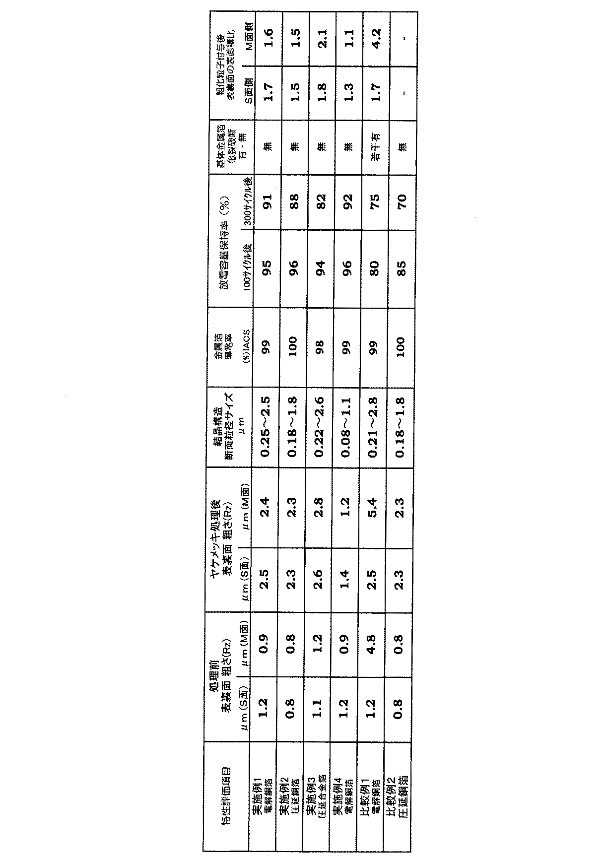
活物質としてシリコン(SiO)を採用し、シリコン(SiO)とアセチレンブラック、PVDF(ポリフッ化ビニリデン)、NMP(N-メチル-2-ビロリドン)を混合してスラリーとした。
活物質層の形成
上記スラリー状とした活物質を各実施例、比較例の銅箔を集電体とし、該集電体上に塗工し、加温乾燥、加熱プレスし、珪素系堆積層(活物質層)として活物質層付き銅箔を作成した。
なお、カーテンコータによる塗布がしやすいように、活物質混合物は発揮性溶剤で、適当なスラリーの粘度に調整した。また、活物質混合物をカーテンコータにより塗布する方法を採用したが、塗布方法は、その他のロールによる塗布方法なども適用できる。 Active Material Granulation Silicon (SiO) was employed as the active material, and silicon (SiO), acetylene black, PVDF (polyvinylidene fluoride), and NMP (N-methyl-2-pyrrolidone) were mixed to form a slurry.
Formation of active material layer The active material in the form of a slurry was used as a current collector for the copper foils of the examples and comparative examples, and coated on the current collector, heated and dried, and heated and pressed to form a silicon-based deposited layer. A copper foil with an active material layer was prepared as (active material layer).
The active material mixture was adjusted to a suitable slurry viscosity with a demonstrable solvent so that it could be easily applied by a curtain coater. Moreover, although the method of apply | coating an active material mixture with a curtain coater was employ | adopted, the application method by the other roll etc. can also be applied for the application method.
作製した負極集電体を電極としてアルゴンガス雰囲気下のグローブボックス中で、三電極式ビーカーセルを作製した。ビーカーセルは、ガラス容器内に入れられた電解液中に、対極(正極)、作用極(負極)、および参照極を浸漬することにより構成した。
電解液としては、エチレンカーボネートとジエチルカーボネートを体積比3:7の割合で混合した溶媒に対し、LiPF6を1モル/リットル溶解した電解液を用いた。対極及び参照極としてはリチウム金属を用いた。 [Preparation of beaker cell]
A three-electrode beaker cell was produced in a glove box under an argon gas atmosphere using the produced negative electrode current collector as an electrode. The beaker cell was configured by immersing a counter electrode (positive electrode), a working electrode (negative electrode), and a reference electrode in an electrolytic solution placed in a glass container.
As the electrolytic solution, an electrolytic solution in which 1 mol / liter of LiPF 6 was dissolved in a solvent in which ethylene carbonate and diethyl carbonate were mixed at a volume ratio of 3: 7 was used. Lithium metal was used as the counter electrode and the reference electrode.
上記のようにして作製したビーカーセルを25℃環境下で4mAの定電流で、作用極(負極)の電位が0V(vs.Li/Li +)に達するまで充電した後、4mAの定電流で作用極の電位が2V(vs.Li/Li +)に達するまで放電し、充放電効率100サイクル後の放電容量保持率にて評価した。
評価結果を表3に併記した。
また、300サイクル充放電を繰り返した後の銅箔の亀裂破断の有無につき確認した結果を表3に併記した。 Evaluation of charge / discharge cycle characteristics After charging the beaker cell produced as described above at a constant current of 4 mA in a 25 ° C. environment until the potential of the working electrode (negative electrode) reaches 0 V (vs. Li / Li +). The discharge was performed at a constant current of 4 mA until the potential of the working electrode reached 2 V (vs. Li / Li +), and the discharge capacity retention rate after 100 cycles of charge / discharge efficiency was evaluated.
The evaluation results are also shown in Table 3.
Moreover, the result confirmed about the presence or absence of the crack fracture of the copper foil after repeating 300 cycles charging / discharging was written together in Table 3.
実施例1の銅箔を集電体として作製したビーカーセル電池での充放電サイクル特性の評価は、全て満足するものであり、300サイクル充放電を繰り返した後の集電体にも亀裂破断は見られなかった。 As shown in Table 3, in the current collector of Example 1, the difference in Rz value of the base copper foil was within the reference value, and the particle size and surface area of the roughened particles after the application of the roughened particles were also within the standard values. It was.
The evaluation of the charge / discharge cycle characteristics in the beaker cell battery prepared using the copper foil of Example 1 as a current collector is all satisfactory, and the current collector after 300 cycles of charge / discharge is also cracked and broken. I couldn't see it.
また、比較例1には、300サイクル充放電を繰り返した後の集電体に亀裂破断が見られた。 On the other hand, Comparative Example 1 used the same untreated copper foil as Example 1, but the difference in roughness Rz value between both surfaces after the roughening treatment was large, and thus the discharge capacity retention after 100 cycles of charge / discharge efficiency was high. It became unsatisfactory.
Moreover, in the comparative example 1, the crack fracture | rupture was seen by the collector after repeating 300 cycles charging / discharging.
2 表面粗化処理槽
3 粗化金属層
4 水洗処理槽
5 防錆処理槽
6 ホッパー
7 ホッパー
8 活物質混合体
9 乾燥装置
10 乾燥装置
11 プレス
12 巻取り機
13 フィルム
14 フィルム供給装置
15 フィルム供給装置
16 貼合せ装置
20 給電電極
22、24,26 電極
31、32 活物質層
33 活物質
35 金属粒子
37 バインダー(導電材) DESCRIPTION OF
Claims (34)
- 金属箔の少なくとも片面に被覆層が設けられ、該被覆層に遊離金属粒子が含まれる被覆層付き金属箔。 A metal foil with a coating layer in which a coating layer is provided on at least one side of the metal foil, and the coating layer contains free metal particles.
- 前記被覆層は遊離金属粒子を含む再溶融が可能な樹脂組成物である請求項1に記載の被覆層付き金属箔。 The metal foil with a coating layer according to claim 1, wherein the coating layer is a remeltable resin composition containing free metal particles.
- 前記被覆層が遊離金属粒子を含む活物質層である請求項1に記載の被覆層付き金属箔。 The metal foil with a coating layer according to claim 1, wherein the coating layer is an active material layer containing free metal particles.
- 前記被覆層が遊離金属粒子を含む再溶融可能な樹脂組成物層であり、該樹脂組成物層上に活物質層が設けられている請求項1に記載の被覆層付き金属箔。 The metal foil with a coating layer according to claim 1, wherein the coating layer is a remeltable resin composition layer containing free metal particles, and an active material layer is provided on the resin composition layer.
- 金属箔の少なくとも片面に粗化処理層が設けられ、該粗化処理層上に被覆層が設けられ、該被覆層に遊離金属粒子が含まれる被覆層付き金属箔。 A metal foil with a coating layer in which a roughening treatment layer is provided on at least one surface of the metal foil, a coating layer is provided on the roughening treatment layer, and free metal particles are contained in the coating layer.
- 前記被覆層に含まれる遊離金属粒子は前記粗化処理層から遊離した金属粒子である請求項5に記載の被覆層付き金属箔。 The metal foil with a coating layer according to claim 5, wherein the free metal particles contained in the coating layer are metal particles released from the roughening treatment layer.
- 前記被覆層が再溶融が可能な樹脂組成物である請求項5または6に記載の被覆層付き金属箔。 The metal foil with a coating layer according to claim 5 or 6, wherein the coating layer is a remeltable resin composition.
- 前記被覆層が活物質層である請求項5または6に記載の被覆層付き金属箔。 The metal foil with a coating layer according to claim 5 or 6, wherein the coating layer is an active material layer.
- 前記被覆層が再溶融可能な樹脂組成物層であり、該樹脂組成物上に活物質層が設けられている請求項5または6に記載の被覆層付き金属箔。 The metal foil with a coating layer according to claim 5 or 6, wherein the coating layer is a remeltable resin composition layer, and an active material layer is provided on the resin composition.
- 前記金属箔が、電解銅箔または圧延銅箔である請求項1~9のいずれに記載の被覆層付き金属箔。 The metal foil with a coating layer according to any one of claims 1 to 9, wherein the metal foil is an electrolytic copper foil or a rolled copper foil.
- 前記遊離金属粒子の粒径が0.05μm~3.5μmである請求項1~9のいずれかに記載の被覆層付き金属箔。 10. The metal foil with a coating layer according to claim 1, wherein a particle diameter of the free metal particles is 0.05 μm to 3.5 μm.
- 前記粗化処理層は、銅、ニッケル、マンガン、鉄、クロム、タングステン、モリブデン、バナジウム、インジウムの少なくとも一つ以上の金属を含有した粗化処理層である請求項5~9のいずれに記載の被覆層付き金属箔。 The roughening treatment layer according to any one of claims 5 to 9, wherein the roughening treatment layer is a roughening treatment layer containing at least one metal of copper, nickel, manganese, iron, chromium, tungsten, molybdenum, vanadium, and indium. Metal foil with coating layer.
- 請求項1~9のいずれかに記載の被覆層付き金属箔の少なくとも最外層表面にフィルムまたは離型紙を設けた被覆層付き金属箔。 10. A metal foil with a coating layer in which a film or a release paper is provided on at least the outermost layer surface of the metal foil with a coating layer according to claim 1.
- 金属箔の少なくとも片面に活物質層が設けられ、該活物質層に遊離金属粒子が含まれる二次電池用電極。 An electrode for a secondary battery in which an active material layer is provided on at least one surface of a metal foil, and the active material layer contains free metal particles.
- 金属箔の少なくとも片面に遊離金属粒子を含有する再溶融可能な樹脂組成物層が設けられ、該樹脂組成物層上に活物質層が設けられている二次電池用電極。 An electrode for a secondary battery in which a remeltable resin composition layer containing free metal particles is provided on at least one surface of a metal foil, and an active material layer is provided on the resin composition layer.
- 金属箔の少なくとも片面に粗化処理層が設けられ、該粗化処理層上に活物質層が設けられ、該活物質層に遊離金属粒子が含まれる二次電池用電極。 An electrode for a secondary battery in which a roughening treatment layer is provided on at least one surface of a metal foil, an active material layer is provided on the roughening treatment layer, and free metal particles are contained in the active material layer.
- 前記活物質層に含まれる遊離金属粒子は前記粗化処理層から遊離した金属粒子である請求項16に記載の二次電池用電極。 The secondary battery electrode according to claim 16, wherein the free metal particles contained in the active material layer are metal particles released from the roughening treatment layer.
- 金属箔の少なくとも片面に粗化処理層が設けられ、該粗化処理層上に遊離金属粒子を含む再溶融可能な樹脂組成物層が設けられ、該樹脂組成物層上に活物質層が設けられている二次電池用電極。 A roughened layer is provided on at least one surface of the metal foil, a remeltable resin composition layer containing free metal particles is provided on the roughened layer, and an active material layer is provided on the resin composition layer. A secondary battery electrode.
- 前記再溶融可能な樹脂組成物層に含まれる遊離金属粒子が前記粗化処理層から遊離した金属粒子である請求項16に記載の二次電池用電極。 The secondary battery electrode according to claim 16, wherein the free metal particles contained in the remeltable resin composition layer are metal particles released from the roughening treatment layer.
- 前記金属箔が、電解銅箔または圧延銅箔である請求項14~17のいずれに記載の二次電池用電極。 The secondary battery electrode according to any one of claims 14 to 17, wherein the metal foil is an electrolytic copper foil or a rolled copper foil.
- 前記遊離金属粒子の粒径が0.05μm~3.5μmである請求項14~17のいずれかに記載の二次電池用電極。 The secondary battery electrode according to any one of claims 14 to 17, wherein a particle diameter of the free metal particles is 0.05 µm to 3.5 µm.
- 前記粗化処理層は、銅、ニッケル、マンガン、鉄、クロム、タングステン、モリブデン、バナジウム、インジウムの少なくとも一つ以上の金属を含有したメッキ浴にて処理、平成された粗化処理層である請求項14~17のいずれに記載の二次電池用電極。 The roughening treatment layer is a roughening treatment layer treated with a plating bath containing at least one metal of copper, nickel, manganese, iron, chromium, tungsten, molybdenum, vanadium, and indium, and Heisei. Item 18. The secondary battery electrode according to any one of Items 14 to 17.
- 請求項14~18のいずれかに記載の二次電池用電極の少なくとも最外層表面にフィルムまたは離型紙を設けた二次電池用電極。 A secondary battery electrode comprising a film or a release paper provided on at least the outermost layer surface of the secondary battery electrode according to any one of claims 14 to 18.
- 前記フィルムが電池用セパレータである請求項21に記載の二次電池用電極。 The secondary battery electrode according to claim 21, wherein the film is a battery separator.
- 金属箔の少なくとも片面に被覆層が設けられ、該被覆層に遊離金属粒子が含まれる被覆層付き金属箔の製造方法であって、
金属箔の表面に電解メッキで、限界電流密度以上に電流を流して、粒径が0.1μm~3.5μmの粗化処理層を施し、
該粗化処理層上に被覆層を形成し、
前記粗化処理粒子の一部を被覆層に遊離金属粒子として混入させる
被覆層付き金属箔の製造方法。 A method for producing a metal foil with a coating layer, wherein a coating layer is provided on at least one side of the metal foil, and the coating layer contains free metal particles,
Electrolytic plating is applied to the surface of the metal foil to apply a roughening treatment layer having a particle size of 0.1 μm to 3.5 μm by passing a current exceeding the limit current density.
Forming a coating layer on the roughened layer;
The manufacturing method of the metal foil with a coating layer which mixes a part of said roughening process particle | grains as a free metal particle in a coating layer. - 前記被覆層が再溶融可能な樹脂組成物層である請求項23に記載の被覆層付き金属箔の製造方法。 The method for producing a metal foil with a coating layer according to claim 23, wherein the coating layer is a remeltable resin composition layer.
- 前記被覆層が活物質層である請求項23に記載の被覆層付き金属箔の製造方法。 The method for producing a metal foil with a coating layer according to claim 23, wherein the coating layer is an active material layer.
- 前記被覆層が再溶融可能な樹脂組成物層であり、該樹脂組成物層上に活物質層が設けられている請求項23に記載の被覆層付き金属箔の製造方法。 The method for producing a metal foil with a coating layer according to claim 23, wherein the coating layer is a remeltable resin composition layer, and an active material layer is provided on the resin composition layer.
- 金属箔の少なくとも片面に被覆層が設けられ、該被覆層に遊離金属粒子が含まれる被覆層付き金属箔の製造方法であって、
金属箔の表面に電解メッキで、限界電流密度以上に電流を流し、粒径が0.1μm~3.5μmの粗化処理層を施し、
該粗化処理層上に、活物質とバインダーと必要により増粘剤とスラリーとを添加し混合した活物質混合体を塗布して活物質層を形成し、
前記活物質層を形成した金属箔を、前記金属処理粒子を活物質層内に導電助剤として取り込むよう乾燥・加圧し、
前記粗化処理粒子を遊離金属粒子として活物質層に含有させる被覆層付き金属箔の製造方法。 A method for producing a metal foil with a coating layer, wherein a coating layer is provided on at least one side of the metal foil, and the coating layer contains free metal particles,
The surface of the metal foil is electrolytically plated, a current exceeding the limit current density is applied, and a roughening treatment layer having a particle size of 0.1 μm to 3.5 μm is applied.
On the roughened layer, an active material mixture obtained by adding and mixing an active material, a binder, and, if necessary, a thickener and a slurry is applied to form an active material layer,
The metal foil on which the active material layer is formed is dried and pressurized so as to incorporate the metal-treated particles into the active material layer as a conductive additive,
The manufacturing method of the metal foil with a coating layer which makes the active material layer contain the said roughening process particle | grains as a free metal particle. - 金属箔の少なくとも片面に被覆層が設けられ、該被覆層に遊離金属粒子が含まれる被覆層付き金属箔の製造方法であって、
金属箔の表面に電解メッキで、限界電流密度以上に電流を流して、粒径が0.1μm~3.5μmの粗化処理層を施し、
該粗化処理層上に再溶融可能な樹脂組成物層を形成し、
該樹脂組成物層上に、活物質とバインダーと必要により増粘剤とスラリーとを添加、混合した活物質混合体を塗布して活物質層を形成し、
前記樹脂組成物層、活物質層が形成された金属箔を、前記粗化処理粒子を樹脂組成物層内に遊離金属粒子として取り込むよう乾燥・加圧する被覆層付き金属箔の製造方法。 A method for producing a metal foil with a coating layer, wherein a coating layer is provided on at least one side of the metal foil, and the coating layer contains free metal particles,
Electrolytic plating is applied to the surface of the metal foil to apply a roughening treatment layer having a particle size of 0.1 μm to 3.5 μm by passing a current exceeding the limit current density.
Forming a remeltable resin composition layer on the roughened layer,
On the resin composition layer, an active material layer is formed by applying an active material mixture in which an active material, a binder, and, if necessary, a thickener and a slurry are added and mixed,
A method for producing a metal foil with a coating layer, wherein the metal foil on which the resin composition layer and the active material layer are formed is dried and pressed so that the roughened particles are incorporated into the resin composition layer as free metal particles. - 請求項23~28のいずれかに記載の被覆層付き金属箔の製造方法で製造された金属箔を用いた二次電池用電極。 An electrode for a secondary battery using a metal foil produced by the method for producing a metal foil with a coating layer according to any one of claims 23 to 28.
- 金属箔の表面に電解メッキで、限界電流密度以上に電流を流し、粒径が0.1μm~3.5μmの粗化処理層を形成する表面粗化処理工程と、
活物質とバインダーと必要により増粘剤とスラリーを添加し混合する活物質造粒工程と、
該粗化処理層の一方の表面上に、前記活物質造粒工程で造粒した活物質混合体を塗布する第一活物質膜形成工程と、
前記活物質混合体をフィルムに堆積して金属箔の他の表面に積層する第二活物質膜形成工程と、
前記第一、第二工程で活物質層を形成した金属箔を、前記粗化処理粒子を活物質層内に導電助剤として取り込むよう乾燥・加圧し、前記粗化処理粒子を遊離金属粒子として活物質層に含有させる乾燥加圧工程と
からなる二次電池用電極の製造方法。 A surface roughening treatment step of forming a roughening treatment layer having a particle size of 0.1 μm to 3.5 μm by passing an electric current exceeding a limit current density by electrolytic plating on the surface of the metal foil;
An active material granulating step of adding and mixing an active material, a binder, and, if necessary, a thickener and a slurry;
A first active material film forming step of applying the active material mixture granulated in the active material granulation step on one surface of the roughened layer;
A second active material film forming step of depositing the active material mixture on a film and laminating it on the other surface of the metal foil;
The metal foil in which the active material layer is formed in the first and second steps is dried and pressurized so that the roughened particles are taken into the active material layer as a conductive additive, and the roughened particles are used as free metal particles. The manufacturing method of the electrode for secondary batteries which consists of the drying pressurization process contained in an active material layer. - 金属箔の表面に電解メッキで、限界電流密度以上に電流を流して、粒径が0.1μm~3.5μmの粗化処理層を形成する表面粗化処理工程と、
該粗化処理層上に再溶融可能な樹脂組成物層を形成する樹脂組成物層形成工程と、
活物質とバインダーと必要により増粘剤とスラリーを添加し混合する活物質造粒工程と、
前記樹脂組成物層の一方の表面上に、前記活物質造粒工程で造粒した活物質混合体を塗布する第一活物質膜形成工程と、
前記活物質混合体をフィルムに堆積して樹脂組成物層の他の表面に積層する第二活物質膜形成工程と、
前記第一、第二工程で活物質層を形成した金属箔を、前記粗化処理粒子を活物質層内に導電助剤として取り込むよう乾燥・加圧し、前記粗化処理粒子を遊離金属粒子として活物質層に含有させる乾燥加圧工程と
からなる二次電池用電極の製造方法。 A surface roughening treatment step of forming a roughening treatment layer having a particle diameter of 0.1 μm to 3.5 μm by passing an electric current exceeding a limit current density by electrolytic plating on the surface of the metal foil;
A resin composition layer forming step of forming a remeltable resin composition layer on the roughened layer;
An active material granulating step of adding and mixing an active material, a binder, and, if necessary, a thickener and a slurry;
A first active material film forming step of applying the active material mixture granulated in the active material granulation step on one surface of the resin composition layer;
A second active material film forming step of depositing the active material mixture on a film and laminating it on the other surface of the resin composition layer;
The metal foil in which the active material layer is formed in the first and second steps is dried and pressurized so that the roughened particles are taken into the active material layer as a conductive additive, and the roughened particles are used as free metal particles. The manufacturing method of the electrode for secondary batteries which consists of the drying pressurization process contained in an active material layer. - 請求項1~13のいずれかに記載の金属箔、請求項23~28のいずれかに記載の製造法で製造された金属箔、または請求項14~22のいずれかに記載の二次電用電極、または請求項30~31のいずれかに記載の製造法で製造された電極を用いたリチウムイオン二次電池。 The metal foil according to any one of claims 1 to 13, the metal foil produced by the production method according to any of claims 23 to 28, or the secondary electric power according to any of claims 14 to 22. A lithium ion secondary battery using an electrode or an electrode produced by the production method according to any one of claims 30 to 31.
Priority Applications (3)
| Application Number | Priority Date | Filing Date | Title |
|---|---|---|---|
| JP2012551413A JP5435519B2 (en) | 2011-07-29 | 2012-06-27 | Metal foil with coating layer for negative electrode of lithium ion secondary battery and method for producing the same, electrode for negative electrode of lithium ion secondary battery and method for producing the same, lithium ion secondary battery |
| KR1020147005454A KR20140051375A (en) | 2011-07-29 | 2012-06-27 | Metal foil with coating layer and method for producing same, secondary cell electrode and method for producing same, and lithium ion secondary cell |
| CN201280037317.1A CN103718346A (en) | 2011-07-29 | 2012-06-27 | Metal foil with coating layer and method for producing same, secondary cell electrode and method for producing same, and lithium ion secondary cell |
Applications Claiming Priority (2)
| Application Number | Priority Date | Filing Date | Title |
|---|---|---|---|
| JP2011-166863 | 2011-07-29 | ||
| JP2011166863 | 2011-07-29 |
Publications (1)
| Publication Number | Publication Date |
|---|---|
| WO2013018473A1 true WO2013018473A1 (en) | 2013-02-07 |
Family
ID=47629007
Family Applications (1)
| Application Number | Title | Priority Date | Filing Date |
|---|---|---|---|
| PCT/JP2012/066439 WO2013018473A1 (en) | 2011-07-29 | 2012-06-27 | Metal foil with coating layer and method for producing same, secondary cell electrode and method for producing same, and lithium ion secondary cell |
Country Status (5)
| Country | Link |
|---|---|
| JP (1) | JP5435519B2 (en) |
| KR (1) | KR20140051375A (en) |
| CN (1) | CN103718346A (en) |
| TW (1) | TW201320454A (en) |
| WO (1) | WO2013018473A1 (en) |
Cited By (5)
| Publication number | Priority date | Publication date | Assignee | Title |
|---|---|---|---|---|
| WO2016039160A1 (en) * | 2014-09-08 | 2016-03-17 | オートリブ ディベロップメント エービー | Vehicle occupant restraint device |
| JP6489252B1 (en) * | 2018-02-15 | 2019-03-27 | Tdk株式会社 | Negative electrode current collector, negative electrode and lithium secondary battery |
| JP6489251B1 (en) * | 2018-02-15 | 2019-03-27 | Tdk株式会社 | Negative electrode current collector, negative electrode and lithium secondary battery |
| JP2019140057A (en) * | 2018-02-15 | 2019-08-22 | Tdk株式会社 | Negative electrode current collector, negative electrode, and lithium secondary battery |
| JP2021521330A (en) * | 2018-04-11 | 2021-08-26 | ハッチンソン テクノロジー インコーポレイテッドHutchinson Technology Incorporated | Plating method to reduce or eliminate voids in solder applied without flux |
Families Citing this family (3)
| Publication number | Priority date | Publication date | Assignee | Title |
|---|---|---|---|---|
| TWI553161B (en) | 2016-03-02 | 2016-10-11 | 華碩電腦股份有限公司 | Method for manufacturing electrode |
| KR20190076769A (en) * | 2017-12-22 | 2019-07-02 | 주식회사 포스코 | Lithium metal negative electrode, manufanturing method thereof and lithium metal battery including the same |
| WO2019163962A1 (en) * | 2018-02-23 | 2019-08-29 | 古河電気工業株式会社 | Electrolytic copper foil, lithium-ion secondary cell negative electrode using electrolytic copper foil, lithium-ion secondary cell, copper-clad laminate and printed wiring board |
Citations (5)
| Publication number | Priority date | Publication date | Assignee | Title |
|---|---|---|---|---|
| JPH07312219A (en) * | 1994-03-24 | 1995-11-28 | Fuji Photo Film Co Ltd | Nonaqueous secondary battery and charging method |
| JP2002246020A (en) * | 2001-02-13 | 2002-08-30 | Sony Corp | Active material and non-aqueous electrolyte battery using the same, and battery producing method |
| JP2004296108A (en) * | 2003-03-25 | 2004-10-21 | Toshiba Corp | Nonaqueous electrolyte battery |
| JP2005353384A (en) * | 2004-06-10 | 2005-12-22 | Mitsui Mining & Smelting Co Ltd | Metal foil with carrier foil, manufacturing method of the same, and collector of nonaqueous electrolyte secondary battery using the same |
| JP2006040652A (en) * | 2004-07-26 | 2006-02-09 | Matsushita Electric Ind Co Ltd | Storage element |
-
2012
- 2012-06-27 WO PCT/JP2012/066439 patent/WO2013018473A1/en active Application Filing
- 2012-06-27 KR KR1020147005454A patent/KR20140051375A/en not_active Application Discontinuation
- 2012-06-27 JP JP2012551413A patent/JP5435519B2/en not_active Expired - Fee Related
- 2012-06-27 CN CN201280037317.1A patent/CN103718346A/en active Pending
- 2012-07-03 TW TW101123840A patent/TW201320454A/en unknown
Patent Citations (5)
| Publication number | Priority date | Publication date | Assignee | Title |
|---|---|---|---|---|
| JPH07312219A (en) * | 1994-03-24 | 1995-11-28 | Fuji Photo Film Co Ltd | Nonaqueous secondary battery and charging method |
| JP2002246020A (en) * | 2001-02-13 | 2002-08-30 | Sony Corp | Active material and non-aqueous electrolyte battery using the same, and battery producing method |
| JP2004296108A (en) * | 2003-03-25 | 2004-10-21 | Toshiba Corp | Nonaqueous electrolyte battery |
| JP2005353384A (en) * | 2004-06-10 | 2005-12-22 | Mitsui Mining & Smelting Co Ltd | Metal foil with carrier foil, manufacturing method of the same, and collector of nonaqueous electrolyte secondary battery using the same |
| JP2006040652A (en) * | 2004-07-26 | 2006-02-09 | Matsushita Electric Ind Co Ltd | Storage element |
Cited By (9)
| Publication number | Priority date | Publication date | Assignee | Title |
|---|---|---|---|---|
| WO2016039160A1 (en) * | 2014-09-08 | 2016-03-17 | オートリブ ディベロップメント エービー | Vehicle occupant restraint device |
| JP6489252B1 (en) * | 2018-02-15 | 2019-03-27 | Tdk株式会社 | Negative electrode current collector, negative electrode and lithium secondary battery |
| JP6489251B1 (en) * | 2018-02-15 | 2019-03-27 | Tdk株式会社 | Negative electrode current collector, negative electrode and lithium secondary battery |
| JP2019140056A (en) * | 2018-02-15 | 2019-08-22 | Tdk株式会社 | Negative electrode current collector, negative electrode and, lithium secondary battery |
| JP2019140057A (en) * | 2018-02-15 | 2019-08-22 | Tdk株式会社 | Negative electrode current collector, negative electrode, and lithium secondary battery |
| JP2019140055A (en) * | 2018-02-15 | 2019-08-22 | Tdk株式会社 | Negative electrode current collector, negative electrode, and lithium secondary battery |
| JP2021521330A (en) * | 2018-04-11 | 2021-08-26 | ハッチンソン テクノロジー インコーポレイテッドHutchinson Technology Incorporated | Plating method to reduce or eliminate voids in solder applied without flux |
| US11674235B2 (en) | 2018-04-11 | 2023-06-13 | Hutchinson Technology Incorporated | Plating method to reduce or eliminate voids in solder applied without flux |
| JP7408566B2 (en) | 2018-04-11 | 2024-01-05 | ハッチンソン テクノロジー インコーポレイテッド | Plating method for reducing or eliminating voids in solder applied without flux |
Also Published As
| Publication number | Publication date |
|---|---|
| TW201320454A (en) | 2013-05-16 |
| KR20140051375A (en) | 2014-04-30 |
| CN103718346A (en) | 2014-04-09 |
| JPWO2013018473A1 (en) | 2015-03-05 |
| JP5435519B2 (en) | 2014-03-05 |
Similar Documents
| Publication | Publication Date | Title |
|---|---|---|
| JP7050419B2 (en) | Negative electrode for all-solid-state secondary battery and all-solid-state secondary battery | |
| TWI570277B (en) | An electrolytic copper foil, an electrolytic copper foil for a lithium ion secondary battery, an electrode for a lithium ion secondary battery using the electrolytic copper foil, and a lithium ion secondary battery using the electrode | |
| JP5435519B2 (en) | Metal foil with coating layer for negative electrode of lithium ion secondary battery and method for producing the same, electrode for negative electrode of lithium ion secondary battery and method for producing the same, lithium ion secondary battery | |
| JP5313761B2 (en) | Lithium ion battery | |
| US9685678B2 (en) | Electrode materials with a synthetic solid electrolyte interface | |
| WO2012091060A1 (en) | Lithium-ion secondary battery, electrode for secondary battery, and electrolytic copper foil for secondary battery electrode | |
| TWI596827B (en) | Method for producing negative electrode material of lithium ion secondary cell and negative electrode material for lithium ion secondary cell | |
| JP5281706B2 (en) | Current collector, current collector manufacturing method, electrode, and secondary battery | |
| JP5448555B2 (en) | Negative electrode for lithium ion secondary battery, lithium ion secondary battery using the same, slurry for preparing negative electrode for lithium ion secondary battery, and method for producing negative electrode for lithium ion secondary battery | |
| JP5437536B2 (en) | Current collector for electrode, negative electrode for non-aqueous electrolyte secondary battery, non-aqueous electrolyte secondary battery | |
| JP2010218848A (en) | Anode for lithium-ion secondary battery, lithium-ion secondary battery using it, manufacturing method of anode for lithium-ion secondary battery, and slurry used for manufacturing | |
| JP2008186704A (en) | Positive electrode plate for non-aqueous secondary battery and non-aqueous secondary battery | |
| JP2008047308A (en) | Nonaqueous electrolyte secondary battery | |
| KR20220018063A (en) | Method of manufacturing a cathode for a secondary battery | |
| CN102549815A (en) | Negative electrode for lithium ion secondary battery, and lithium ion secondary battery | |
| JP2010244767A (en) | Method for manufacturing anode for lithium secondary battery | |
| JP6067256B2 (en) | Electrolytic copper foil, negative electrode for lithium ion secondary battery, and lithium ion secondary battery | |
| JP2008047306A (en) | Nonaqueous electrolyte secondary battery | |
| JP2013012450A (en) | Metal foil for collector of lithium ion secondary battery electrode, method of manufacturing the metal foil, and lithium ion secondary battery using the metal foil as collector | |
| WO2018062264A1 (en) | Electrode and secondary cell | |
| JP2014009365A (en) | Electrolytic copper foil, lithium ion secondary battery negative pole electrode, and lithium ion secondary battery |
Legal Events
| Date | Code | Title | Description |
|---|---|---|---|
| ENP | Entry into the national phase |
Ref document number: 2012551413 Country of ref document: JP Kind code of ref document: A |
|
| 121 | Ep: the epo has been informed by wipo that ep was designated in this application |
Ref document number: 12819713 Country of ref document: EP Kind code of ref document: A1 |
|
| NENP | Non-entry into the national phase |
Ref country code: DE |
|
| ENP | Entry into the national phase |
Ref document number: 20147005454 Country of ref document: KR Kind code of ref document: A |
|
| 122 | Ep: pct application non-entry in european phase |
Ref document number: 12819713 Country of ref document: EP Kind code of ref document: A1 |