WO2013018347A1 - Magnetic field measuring device - Google Patents
Magnetic field measuring device Download PDFInfo
- Publication number
- WO2013018347A1 WO2013018347A1 PCT/JP2012/004813 JP2012004813W WO2013018347A1 WO 2013018347 A1 WO2013018347 A1 WO 2013018347A1 JP 2012004813 W JP2012004813 W JP 2012004813W WO 2013018347 A1 WO2013018347 A1 WO 2013018347A1
- Authority
- WO
- WIPO (PCT)
- Prior art keywords
- magnetic field
- magnetoelectric
- magnetic
- calculation
- output
- Prior art date
Links
Images


Classifications
-
- G—PHYSICS
- G01—MEASURING; TESTING
- G01B—MEASURING LENGTH, THICKNESS OR SIMILAR LINEAR DIMENSIONS; MEASURING ANGLES; MEASURING AREAS; MEASURING IRREGULARITIES OF SURFACES OR CONTOURS
- G01B7/00—Measuring arrangements characterised by the use of electric or magnetic techniques
- G01B7/14—Measuring arrangements characterised by the use of electric or magnetic techniques for measuring distance or clearance between spaced objects or spaced apertures
-
- G—PHYSICS
- G01—MEASURING; TESTING
- G01R—MEASURING ELECTRIC VARIABLES; MEASURING MAGNETIC VARIABLES
- G01R33/00—Arrangements or instruments for measuring magnetic variables
- G01R33/02—Measuring direction or magnitude of magnetic fields or magnetic flux
- G01R33/06—Measuring direction or magnitude of magnetic fields or magnetic flux using galvano-magnetic devices
- G01R33/07—Hall effect devices
- G01R33/072—Constructional adaptation of the sensor to specific applications
-
- G—PHYSICS
- G01—MEASURING; TESTING
- G01D—MEASURING NOT SPECIALLY ADAPTED FOR A SPECIFIC VARIABLE; ARRANGEMENTS FOR MEASURING TWO OR MORE VARIABLES NOT COVERED IN A SINGLE OTHER SUBCLASS; TARIFF METERING APPARATUS; MEASURING OR TESTING NOT OTHERWISE PROVIDED FOR
- G01D5/00—Mechanical means for transferring the output of a sensing member; Means for converting the output of a sensing member to another variable where the form or nature of the sensing member does not constrain the means for converting; Transducers not specially adapted for a specific variable
- G01D5/12—Mechanical means for transferring the output of a sensing member; Means for converting the output of a sensing member to another variable where the form or nature of the sensing member does not constrain the means for converting; Transducers not specially adapted for a specific variable using electric or magnetic means
- G01D5/14—Mechanical means for transferring the output of a sensing member; Means for converting the output of a sensing member to another variable where the form or nature of the sensing member does not constrain the means for converting; Transducers not specially adapted for a specific variable using electric or magnetic means influencing the magnitude of a current or voltage
- G01D5/142—Mechanical means for transferring the output of a sensing member; Means for converting the output of a sensing member to another variable where the form or nature of the sensing member does not constrain the means for converting; Transducers not specially adapted for a specific variable using electric or magnetic means influencing the magnitude of a current or voltage using Hall-effect devices
- G01D5/145—Mechanical means for transferring the output of a sensing member; Means for converting the output of a sensing member to another variable where the form or nature of the sensing member does not constrain the means for converting; Transducers not specially adapted for a specific variable using electric or magnetic means influencing the magnitude of a current or voltage using Hall-effect devices influenced by the relative movement between the Hall device and magnetic fields
-
- G—PHYSICS
- G01—MEASURING; TESTING
- G01D—MEASURING NOT SPECIALLY ADAPTED FOR A SPECIFIC VARIABLE; ARRANGEMENTS FOR MEASURING TWO OR MORE VARIABLES NOT COVERED IN A SINGLE OTHER SUBCLASS; TARIFF METERING APPARATUS; MEASURING OR TESTING NOT OTHERWISE PROVIDED FOR
- G01D5/00—Mechanical means for transferring the output of a sensing member; Means for converting the output of a sensing member to another variable where the form or nature of the sensing member does not constrain the means for converting; Transducers not specially adapted for a specific variable
- G01D5/12—Mechanical means for transferring the output of a sensing member; Means for converting the output of a sensing member to another variable where the form or nature of the sensing member does not constrain the means for converting; Transducers not specially adapted for a specific variable using electric or magnetic means
- G01D5/14—Mechanical means for transferring the output of a sensing member; Means for converting the output of a sensing member to another variable where the form or nature of the sensing member does not constrain the means for converting; Transducers not specially adapted for a specific variable using electric or magnetic means influencing the magnitude of a current or voltage
- G01D5/142—Mechanical means for transferring the output of a sensing member; Means for converting the output of a sensing member to another variable where the form or nature of the sensing member does not constrain the means for converting; Transducers not specially adapted for a specific variable using electric or magnetic means influencing the magnitude of a current or voltage using Hall-effect devices
- G01D5/147—Mechanical means for transferring the output of a sensing member; Means for converting the output of a sensing member to another variable where the form or nature of the sensing member does not constrain the means for converting; Transducers not specially adapted for a specific variable using electric or magnetic means influencing the magnitude of a current or voltage using Hall-effect devices influenced by the movement of a third element, the position of Hall device and the source of magnetic field being fixed in respect to each other
-
- G—PHYSICS
- G01—MEASURING; TESTING
- G01D—MEASURING NOT SPECIALLY ADAPTED FOR A SPECIFIC VARIABLE; ARRANGEMENTS FOR MEASURING TWO OR MORE VARIABLES NOT COVERED IN A SINGLE OTHER SUBCLASS; TARIFF METERING APPARATUS; MEASURING OR TESTING NOT OTHERWISE PROVIDED FOR
- G01D5/00—Mechanical means for transferring the output of a sensing member; Means for converting the output of a sensing member to another variable where the form or nature of the sensing member does not constrain the means for converting; Transducers not specially adapted for a specific variable
- G01D5/12—Mechanical means for transferring the output of a sensing member; Means for converting the output of a sensing member to another variable where the form or nature of the sensing member does not constrain the means for converting; Transducers not specially adapted for a specific variable using electric or magnetic means
- G01D5/244—Mechanical means for transferring the output of a sensing member; Means for converting the output of a sensing member to another variable where the form or nature of the sensing member does not constrain the means for converting; Transducers not specially adapted for a specific variable using electric or magnetic means influencing characteristics of pulses or pulse trains; generating pulses or pulse trains
- G01D5/245—Mechanical means for transferring the output of a sensing member; Means for converting the output of a sensing member to another variable where the form or nature of the sensing member does not constrain the means for converting; Transducers not specially adapted for a specific variable using electric or magnetic means influencing characteristics of pulses or pulse trains; generating pulses or pulse trains using a variable number of pulses in a train
- G01D5/2451—Incremental encoders
-
- G—PHYSICS
- G01—MEASURING; TESTING
- G01D—MEASURING NOT SPECIALLY ADAPTED FOR A SPECIFIC VARIABLE; ARRANGEMENTS FOR MEASURING TWO OR MORE VARIABLES NOT COVERED IN A SINGLE OTHER SUBCLASS; TARIFF METERING APPARATUS; MEASURING OR TESTING NOT OTHERWISE PROVIDED FOR
- G01D2205/00—Indexing scheme relating to details of means for transferring or converting the output of a sensing member
- G01D2205/40—Position sensors comprising arrangements for concentrating or redirecting magnetic flux
Definitions
- the present invention relates to a magnetic field measurement apparatus, and more particularly to a magnetic field measurement apparatus that detects the position, movement, or rotation of a magnetic field generator.
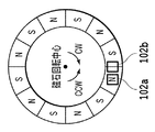
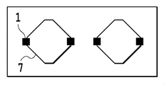
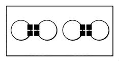
- FIG. 1A to 1C are diagrams for explaining a conventional magnetic encoder, and a magnetic sensor such as a multipolar magnet and a Hall IC as shown in FIG. 1A is used.
- the Hall ICs 102a and 102b are arranged such that the phase difference between the output pulses is shifted by 90 degrees in electrical angle.
- FIG. 2 is a block diagram of a commonly used Hall IC, in which the Hall element 101, the amplifier 130, the Schmitt circuit 131, and the driver are integrated.
- a Hall IC is widely used in fields such as a magnetic pulse encoder.
- the Hall IC amplifies the Hall electromotive force output in proportion to the magnetic field applied to the magnetosensitive surface of the Hall element 101 by the amplifier 130, and then compares it with an arbitrary threshold value by the Schmitt circuit. , Operate to digitally output the result.
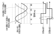
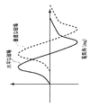
- FIG. 1B shows the magnetic field applied to the Hall elements in the Hall ICs 102a and 102b when the magnet is rotated in the CCW direction from the center when the state shown in FIG. It shows the output of each Hall IC.
- 1C is applied to the Hall elements in the Hall ICs 102a and 102b when the magnet shown in FIG. 1A is rotated about the magnet in the CW direction when the electrical angle is 0 degree. It shows the magnetic field and the output of each Hall IC.
- the direction of rotation can be detected by using the rise or fall of either Hall IC output as a trigger and seeing whether the other Hall IC output is HIGH or LOW. It becomes.
- the fall of the Hall IC 102b is used as a trigger.
- the sensor can operate even when the distance between the multipolar magnet and the sensor is increased, that is, the magnetic field strength applied to the sensor is low, There is a growing demand for low jitter output and an output that accurately corresponds to the pole pitch of a multipolar magnet (generally called an output duty requirement) even in environments where disturbance magnetic noise is poor. .
- the present invention has been made in view of such problems.
- the object of the present invention is to reduce the influence of disturbance magnetic noise particularly in an application for detecting the position, movement or rotation of a detected object such as a wheel speed sensor. It is another object of the present invention to provide a magnetic field measuring apparatus that can be removed and that can provide accurate duty output with low jitter even when the magnetic field intensity generated by the detection object applied to the sensor apparatus is low. .
- the present invention has been made in order to achieve such an object, and the invention according to claim 1 is a magnetic field measuring apparatus for detecting the strength of a magnetic field generated from a magnetic field generator. 4, a magnetic converging plate made of a magnetic material, and a calculation unit that calculates the intensity of a magnetic field applied in a horizontal direction and / or a vertical direction with respect to the magnetosensitive surface of the magnetoelectric conversion element.
- the magnetic converging plate generates a magnetic field vector generated in the horizontal direction with respect to the magnetosensitive surface of the first magnetoelectric transducer and the magnetosensitive surface of the second magnetoelectric transducer.
- the magnetic surface is converted into a magnetic field vector perpendicular to and opposite to the magnetic sensitive surface of the second magnetoelectric transducer and the magnetic sensitive surface of the third magnetoelectric transducer and the second magnetoelectric transducer.
- the first to fourth magnetic fields are converted into magnetic field vectors perpendicular to and opposite to the magnetic sensitive surfaces of the third magnetoelectric transducer and the fourth magnetoelectric transducer.
- the calculation unit includes a first calculation block that adds and subtracts outputs of the first to fourth magnetoelectric conversion elements and outputs a calculation result. .
- the invention according to claim 2 is a magnetic field measuring apparatus for detecting the strength of a magnetic field generated from a magnetic field generator, wherein the first to fourth magnetoelectric transducers and the magnetosensitive surface of the magnetoelectric transducer are provided.
- a calculation unit that calculates the strength of the magnetic field applied in the horizontal direction and / or the vertical direction.
- the calculation unit adds and subtracts the outputs of the first to fourth magnetoelectric transducers, and calculates the calculation result.
- a signal that is 90 degrees out of phase with the output signal of the first calculation block is calculated by adding and subtracting the outputs of the first calculation block to be output and the first to fourth magnetoelectric transducers, and outputs the calculation result A second calculation block.
- the first calculation block adds or subtracts the outputs of the first and second magnetoelectric transducers.
- a first addition / subtraction block for outputting a calculation result
- a second addition / subtraction block for adding / subtracting outputs of the third magnetoelectric conversion element and the fourth magnetoelectric conversion element, and outputting a calculation result
- a third addition / subtraction block for adding / subtracting the output of the addition / subtraction block and the output of the second addition / subtraction block and outputting a calculation result.
- the first calculation block adds or subtracts the outputs of the first and third magnetoelectric transducers.
- a first addition / subtraction block for outputting a calculation result
- a second addition / subtraction block for adding / subtracting outputs of the second magnetoelectric conversion element and the fourth magnetoelectric conversion element, and outputting a calculation result
- the first And a third addition / subtraction block for adding / subtracting the output of the addition / subtraction block and the output of the second addition / subtraction block and outputting a calculation result.
- the calculation unit adds or subtracts the outputs of the first to fourth magnetoelectric transducers, and the first It has the 2nd calculation block which calculates the signal from which a phase differs from the output signal of a calculation block, It is characterized by the above-mentioned.
- the phase difference between the output signal of the first calculation block and the output signal of the second calculation block is 90 degrees. It is characterized by.
- the invention according to claim 7 is the invention according to claim 5 or 6, wherein the second calculation block adds or subtracts outputs of the first magnetoelectric conversion element and the second magnetoelectric conversion element.
- a fourth addition / subtraction block for outputting a calculation result
- a fifth addition / subtraction block for adding / subtracting outputs of the third magnetoelectric conversion element and the fourth magnetoelectric conversion element, and outputting a calculation result
- a sixth addition / subtraction block for adding / subtracting the output of the addition / subtraction block and the output of the fifth addition / subtraction block and outputting the calculation result.
- the invention according to claim 8 is the invention according to claim 5 or 6, wherein the second calculation block adds or subtracts outputs of the first magnetoelectric conversion element and the third magnetoelectric conversion element.
- a fourth addition / subtraction block for outputting a calculation result
- a fifth addition / subtraction block for adding / subtracting the outputs of the second magnetoelectric conversion element and the fourth magnetoelectric conversion element, and outputting a calculation result
- a sixth addition / subtraction block for adding / subtracting the output of the addition / subtraction block and the output of the fifth addition / subtraction block and outputting the calculation result.
- the invention according to claim 9 is the invention according to any one of claims 1 to 8, characterized in that the first to fourth magnetoelectric transducers are arranged substantially linearly.
- the invention according to claim 10 is the invention according to any one of claims 1 to 9, wherein the calculation unit detects the position, movement, or rotation of the magnetic field generator.
- the calculation unit detects the position, movement, or rotation of the magnetic field generator based on the output of the first calculation block. It is characterized by that.
- the calculation unit in the invention of the tenth or eleventh aspect, the calculation unit generates the magnetic field based on a signal obtained by shaping the output signal of the first calculation block into a pulse waveform. It is characterized by detecting the position, movement or rotation of the body.
- the invention according to claim 13 is the invention according to any one of claims 5 to 8, wherein the calculation unit includes an output of the first calculation block, an output of the second calculation block, Based on the above, the position, movement or rotation of the magnetic field generator is detected.
- the invention according to claim 14 is the invention according to any one of claims 1 to 13, further comprising a magnetic field generator, wherein the magnetic field generator is movable and / or rotatable multipole magnetized. It is a structure comprising a magnet or a back-bias magnet installed in the vicinity of the first to fourth magnetoelectric transducers, and movable and / or rotatable gear teeth.
- the invention according to claim 15 is the invention according to any one of claims 1 to 13, further comprising a magnetic field generator, wherein the magnetic field generator is installed in the vicinity of the first to fourth magnetoelectric transducers.
- a back bias magnet and a movable and / or rotatable gear tooth, and the first to fourth magnetoelectric transducers are positioned between the back bias magnet and the gear tooth. It is characterized by being arranged in.
- the present invention can be applied to an application for detecting the position, movement or rotation of a detected object, and removes the influence of disturbance magnetic noise when detecting the position, movement or rotation of the detected object.
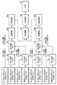
- FIG. 1 It is a figure for demonstrating the conventional magnetic encoder. It is a figure for demonstrating the conventional magnetic encoder. It is a figure for demonstrating the conventional magnetic encoder. It is a figure for demonstrating the conventional magnetic encoder. It is a block diagram of Hall IC generally used conventionally. It is a block diagram for demonstrating each embodiment as a magnetic field measuring apparatus which concerns on this invention. It is a side view of the magnetic convergence plate sensor part 9 shown in FIG. It is a figure for demonstrating the role of the magnetic convergence board shown in FIG. It is a figure which shows the internal signal of the detection magnetic field in the magnetic field measuring apparatus which concerns on this invention. It is the figure which showed the arrangement
- FIG. 1 It is a figure for demonstrating the conventional magnetic encoder. It is a figure for demonstrating the conventional magnetic encoder. It is a figure for demonstrating the conventional magnetic encoder.
- FIG. It is a figure which shows the result of the signal calculation for one electrical angle cycle. It is a figure which shows the result of the signal calculation for one electrical angle cycle. It is a figure which shows the result of the signal calculation for one electrical angle cycle. It is a figure for demonstrating the signal processing in the present Example 1.
- FIG. It is a figure for demonstrating the signal processing in the present Example 1.
- FIG. It is a figure which shows the output waveform of the output shaping
- FIG. It is a figure which shows the example of the waveform in the present Examples 1, 2, and 3.
- FIG. It is a figure which shows the example of the waveform in the present Examples 1, 2, and 3.
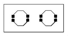
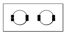
- FIG. 6 is a top view for explaining a magnetic field measurement apparatus according to a third embodiment. It is a figure which shows the example of the magnetic convergence board shape which can be used in Example 1,2,3. It is a figure which shows the example of the magnetic convergence board shape which can be used in Example 1,2,3.
- the magnetic field measurement device of the present invention is applied to rotation detection of the detection object.
- the magnetic field measurement device of the present invention is applied to position detection of the detection object.
- the magnetic field measurement apparatus of the present invention is applied to the detection of gear teeth.
- Example 1 The first embodiment relates to a magnetic field measuring apparatus in the case where the rotation detection body is a multipolar ring magnet and the magnetoelectric conversion element is detected using a Hall element.
- the sensor configuration for explaining the magnetic field measurement apparatus in the first embodiment is shown in FIG. 3, the top view for explaining the magnetic field measurement apparatus is FIG. 8, the side view is FIG. 7, and the signal processing is explained.
- FIG. 6 and FIG. 18 are block diagrams.
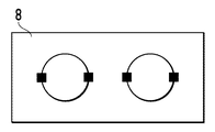
- FIG. 3 is a block diagram for explaining each embodiment as a magnetic field measuring apparatus according to the present invention.
- the sensor unit in the first embodiment has a configuration in which a Hall element is manufactured on a silicon substrate and a magnetic converging plate made of a thin magnetic material is manufactured in the vicinity thereof, and is roughly divided into two locations (sensor unit 9, 10).
- the sensor section here is composed of a magnetic converging plate made of a Hall element and a magnetic material, and each sensor section can detect a horizontal magnetic field and a vertical magnetic field applied to the sensor surface independently. It is.
- the detailed sensor configuration is as follows. 1 (LL) is the first Hall element in the left sensor unit 9, 1 (LR) is the second Hall element in the left sensor unit 9, and 1 (RL) is the third Hall element in the right sensor unit 10.
- Hall element, 1 (RR) is a fourth Hall element in the right sensor unit 10
- 7 is a magnetic converging plate made of a magnetic material
- 8 is a silicon substrate
- 11 is a magnetic sensing part in the left sensor unit.
- the center, 12 is the center of the magnetic sensor part in the right sensor part
- the symbol B is the distance between the left and right magnetic sensor parts (2 mm in this embodiment).
- the first Hall element to the fourth Hall element are arranged so that the normal direction of the magnetic sensitive surface of the Hall element (direction of the magnetic sensitive surface) is substantially the same.
- the center of the magnetically sensitive part referred to here represents the center of symmetry in each sensor part.
- the Hall element is preferably installed at the lower end of the magnetic flux concentrating plate.
- the arrangement is not necessarily limited to this as long as the sensitivity necessary for effective rotation detection is obtained.
- the magnetic converging plate and the Hall element have a mirror image relation with respect to a mirror surface parallel to the YZ plane passing through the center of the magnetically sensitive part of each sensor part.
- the present invention is not necessarily limited to this as long as it does not have a significant effect on disturbance offset removal and duty performance, which will be described later.
- the pitch A of the magnets and the distance B between the centers of the magnetically sensitive parts are made to coincide. This is so that magnetic fields having a phase difference of 180 degrees are input to the centers of the magnetic sensing portions.
- the sensor unit is defined as being on the XY plane.
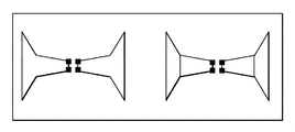
- FIG. 4 is a diagram for explaining the role of the magnetic flux concentrating plate shown in FIG. Here, the effect of the magnetic focusing plate will be described with reference to FIG.
- FIG. 4 shows the state of the magnetic path when the magnetic focusing plate is installed in a uniform horizontal magnetic field.
- the magnetic converging plate has a characteristic of converting a horizontal magnetic field into a vertical magnetic field, and as shown in FIG. 4, the horizontal magnetic field is direction-converted into a vertical magnetic field in the Hall element section.
- the magnetic flux concentrator plate generates a magnetic field vector generated in a horizontal direction with respect to the magnetic sensitive surface of the first Hall element and the magnetic sensitive surface of the second Hall element, and The magnetic field vector is converted into a magnetic field vector perpendicular to each of the magnetic sensing surfaces of the Hall element and in the opposite direction to each of the magnetic sensing surfaces, and with respect to the magnetic sensing surface of the third Hall element and the fourth Hall element.
- the magnetic field vector generated in the horizontal direction is converted into a magnetic field vector perpendicular to and opposite to the magnetic sensitive surface of the third Hall element and the magnetic sensitive surface of the fourth Hall element. As described above, they are arranged in the vicinity of the first to fourth Hall elements.
- the horizontal magnetic field strength applied to each sensor unit is multiplied by a certain coefficient to be converted into a vertical magnetic field.
- the size of the Hall element magnetic sensing surface is 30 ⁇ m ⁇ 30 ⁇ m, this coefficient is approximately 7.3 times. This coefficient is called a magnetic amplification factor. This coefficient depends on the shape and size of the magnetic focusing plate.
- the vertical z-direction magnetic field is also somewhat amplified and input to the lower end of the magnetic focusing plate, which is approximately 1.2 times.
- the main reason for installing the magnetic converging plate mirror-symmetrically as shown in FIG. 4 will be described in detail later, in addition to the formation of a magnetic circuit capable of remarkably improving the magnetic amplification factor.
- the output signal is calculated to decompose and detect the magnetic field in the z direction and the magnetic field in the x direction, and to eliminate the influence of a disturbance magnetic field described later.
- the above-described magnetic amplification factor varies depending on the shape and size of each magnetic converging plate, so that the effect of removing the influence of the disturbance magnetic field is deteriorated, or the Z direction and X direction are decomposed by calculation. You will not be able to do it accurately. As is apparent from FIG.
- the magnetic field strength applied to each Hall element is negative in the z direction for 1 (LL) and positive in the z direction for 1 (LL) in a uniform horizontal magnetic field in space.
- Direction is changed. That is, when a sinusoidal magnetic field is applied, the phase difference is 180 degrees.
- the magnetic field is input in the z direction plus with respect to 1 (LL) and 1 (LR). That is, when a sinusoidal magnetic field is applied in the vertical direction, the phase difference is 0 degrees.
- FIG. 7 is a side view showing the positional relationship between the detected object and the Hall element
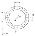
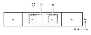
- FIG. 8 is a top view for explaining the magnetic field measurement apparatus according to the first embodiment.
- symbol A represents the pitch distance (2 mm in this embodiment) between the north and south poles of the multipole magnet.
- Reference numeral 16 denotes a 12-pole ring magnet which is a rotating body (detected body), 17 denotes a rotating shaft of the rotating body, and ⁇ 1 denotes a rotation angle.
- the rotation axis is defined as being parallel to the Z axis and rotating about the rotation shaft rotation axis 18.
- the currently described diagram is defined as a rotation angle of 0 degrees and represents a state of rotating counterclockwise in the diagram.
- the multipolar ring magnet 16 moves and rotates in the magnetization direction.
- the respective magnetic sensing part centers 11 and 12 are in the vicinity of the XY coordinates on the circle 19 formed by the midpoint of the inner and outer diameters of the multipolar ring magnet 16 and are separated from the ring magnet by a certain distance. At this time, the sensor substrate is substantially parallel to the ring magnet surface.
- first to fourth Hall elements are arranged substantially linearly along the magnetization direction of the multipolar ring magnet.
- FIG. 6 is a diagram showing an internal signal of a detected magnetic field in the magnetic field measuring apparatus, and is a diagram showing a signal flow of each Hall element.
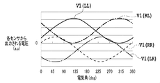
- the output voltage from the Hall element 1 (LL) is V1 (LL)
- the output voltage from the Hall element 1 (LR) is V1 (LR)
- the output voltage from the Hall element 1 (RL) is V1 (RL).
- the output voltage from the Hall element 1 (RR) is V1 (RR)
- the difference between V1 (LR) and V1 (LL) is V2
- the difference between V1 (RL) and V1 (RR) is
- V3 the sum of V1 (LL) and V1 (LR) is taken as V4
- the sum of V1 (RL) and V1 (RR) is taken as V5
- the difference between V2 and V3 is taken.
- the result obtained is V (0), and the difference between V4 and V5 is V (90).
- Signals are input to a signal amplification unit that performs amplification, a signal comparison unit that performs signal comparison, a comparison operation unit that analyzes a comparison state, an output shaping unit that generates an output state, and an output unit that performs final output. Specific details will be described later.
- the magnetic fields applied to the magnetically sensitive part center 11 in the sensor unit 9 and the magnetically sensitive part center 12 in the sensor unit 10 by the 12-pole magnet are accompanied by the counterclockwise rotation of the multipolar ring magnet. It can be approximated by a sine wave / cosine wave as shown in the following equation.
- the expression (1) is the magnetic flux density in the z direction perpendicular to the sensor surface input to the magnetic sensing part center 11 shown in FIG. 3, and the expression (2) is the sensor surface input to the magnetic sensing part center 12.
- B′0 is the magnetic flux density amplitude in the vertical z direction output from the ring magnet 16
- B0 is the magnetic flux density amplitude in the horizontal x direction output from the ring magnet 16
- Bzoffset (t ) Represents a disturbance magnetic field (magnetic noise) in the z direction at a certain time
- Bxoffset (t) represents a disturbance magnetic field (magnetic noise) in the x direction at a certain time.
- the disturbance magnetic field (magnetic noise) in the y direction is ignored because the sensor cannot detect the magnetic field in the y direction.
- ⁇ is an electrical angle
- ⁇ ⁇ 1 ⁇ N / 2 obtained by multiplying the rotation angle (mechanical angle) ⁇ 1 by half the number of poles N. .
- the sensor units 9 and 10 to which the magnetic field as described in [Equation 1] is applied multiply the magnetic flux density horizontal to the sensor surface by the effect of the magnetic converging plate K times (the vertical magnetic field conversion rate from the horizontal magnetic field). To a magnetic field perpendicular to the Hall element magnetic sensing surface. Further, the magnetic flux density perpendicular to the sensor surface is multiplied by K '(perpendicular magnetic field amplification factor), and becomes a magnetic field perpendicular to the Hall element magnetosensitive surface.
- Equation (5) is a magnetic flux density perpendicular to the Hall element magnetosensitive surface input to 1 (LL)
- Equation (6) is a magnetic flux density perpendicular to the Hall element magnetosensitive surface input to 1 (LR)
- Equation (7) is the magnetic flux density perpendicular to the Hall element magnetosensitive surface input to 1 (RL)
- Equation (8) is the magnetic flux density perpendicular to the Hall element magnetosensitive surface input to 1 (RR).
- ⁇ represents a deviation from the phase difference of 180 degrees between the left and right Hall elements in the sensor units 9 and 10, which is largely generated only in a magnetic field horizontal to the sensor surface.
- the phase shift ⁇ from 180 degrees occurs because the magnetic field in the x direction (horizontal direction) is not completely horizontal but non-uniform with respect to each sensor unit generated from the multipolar magnet. At this time, although a slight phase shift occurs even in a perpendicular magnetic field, it is very small, so it is ignored in this description.
- ⁇ is a constant determined by the size of the multipolar magnet, the size of the magnetic converging plate, the size of the magnet and the arrangement thereof.
- V / T which is the output voltage per unit magnetic flux density of the Hall element
- the Hall elements 1 (LL), 1 (LR), 1 (RL), 1 (RR) ) Voltage outputs V1 (LL), V1 (LR), V1 (RL), and V1 (RR) are expressed by the following equations.
- V2, V3, V4, and V5 are obtained by calculating the sum and difference of the voltage obtained here by the signal processing of FIG.
- V (0) and V (90) as shown in FIG. 6 are obtained as follows.
- FIG. 9 shows the results of main magnetic flux density and voltage signal calculation when the electrical angle is rotated for one period of the above-described period (the 12-pole ring magnet 16 corresponds to a mechanical angle of 30 degrees).
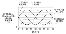
- FIG. 9A to 9C are diagrams showing the results of signal calculation for one electrical angle cycle.
- each magnetic flux density and output voltage largely change depending on the size / shape of the magnet, the gap between the sensor and the magnet, the magnet magnetization method, etc. a. It is expressed as u (arbitrary unit). This is not a problem when the present embodiment is described.
- FIG. 9A shows changes in the horizontal and vertical magnetic flux densities applied to the magnetically sensitive parts centers 11 and 12 of the sensor parts 9 and 10, and FIG. 9B shows the output voltage from each Hall element.
- the horizontal and vertical magnetic flux density applied to the center of each sensor portion is substantially sinusoidal or cosine wave centered on 0, but when disturbance magnetic noise is applied, FIG.
- the waveform has an offset that is not centered on zero.
- noise is applied for an arbitrary time in one cycle.
- the signals V (0) and V (90) after the calculation in FIG. Using this phase difference, the rotation direction can be detected. Furthermore, the signals V (0) and V (90) are sine wave / cosine wave signals without the influence of the disturbance magnetic noise included in FIG. 9A. I understand.
- the signals V (0) and V (90) obtained by the equations (17) and (18) cancel the disturbance magnetic noise due to the phase difference of 90 degrees, and only the magnetic field signal generated by the magnet. It can be seen that the output voltage is amplified. Further, in the present shape (described in FIG. 3, the thickness of the magnetic converging plate z direction is 30 ⁇ m), the magnetic simulation result K is about 7.3 times, and the above-described phase difference ⁇ is about 60 degrees. Therefore, with regard to the equation (17), the horizontal magnetic field with respect to the sensor surface by the magnetic focusing plate is 6.3 times (7.3 ⁇ cos (30 °)) as the actual magnetic flux density (vertical magnetic field amplification factor K ′ Is about 1.2).
- the parameters are as described above.
- the parameter Kcos ( ⁇ / 2) is set to 0 ⁇ Kcos ( The adjustment can be made within the range of ⁇ / 2) ⁇ 10, and the user may specify an optimum parameter in consideration of the size. From this example, if a large parameter of K cos ( ⁇ / 2) is used, an extremely large S / N can be obtained as compared with a single Hall element. For this reason, the jitter caused by the circuit noise of the output can be remarkably reduced.
- the signal amplifying unit 51 is a signal amplifying unit having an auto gain control function for amplifying an input waveform up to a certain predetermined output.
- the signal comparison unit 52 is a signal comparison unit configured by a hysteresis comparator or the like for converting an analog input waveform into a digital pulse output while preventing chattering of the comparator.
- the signal calculation unit 53 has a function of observing the output state of the other when the rising or falling edge of one output of the signal comparison unit 52 is detected, and determining the rotation direction. Rotation direction information and edge switching timing information.
- the output shaping unit 54 generates an output pulse waveform based on the output of the signal calculation unit 53.
- the output unit 55 is a driver.
- V (0) and V (90) shown in the equations (17) and (18) obtained up to the outputs of the third subtraction block and the fourth subtraction block are respectively sent to the signal amplification units 51a and 51b.
- the input and amplified output signals are respectively input to comparators with hysteresis (signal comparison unit) as shown in FIG. 10A, and the compared signals are output as shown in FIG. 10B.
- Vref1 and Vref2 in FIG. 10B are threshold values of the hysteresis comparator. The reason why the hysteresis comparator is used here is to prevent chattering of the output due to circuit noise by providing hysteresis.
- the threshold value of the hysteresis comparator is the same in the signal comparison unit 52a and the signal comparison unit 52b.
- the comparison operation unit 53 creates a digital signal of an instruction for outputting a pulse of time information from the output unit every time the output of the signal comparison unit 52a changes from high to low or low to high (the magnetic converging plate generates a magnetic signal). It is preferably created using V (0) which is a magnetic field information signal in the horizontal direction with respect to the Hall element magnetosensitive surface which has been amplified and improved in S / N.
- V (0) is a magnetic field information signal in the horizontal direction with respect to the Hall element magnetosensitive surface which has been amplified and improved in S / N.
- the comparison operation unit 53 checks the output state of the signal comparison unit 52a using the rise and fall of the output of the signal comparison unit 52b as a trigger as described above, determines the rotation direction accordingly, and outputs the contents.
- the High state time is changed in the pulse period in accordance with the rotation direction described above, and output (t1 and t2 in FIG. 11 are different).
- a method of outputting the rotation direction by changing the time of the Low state can be used.
- rotation information is added to the final pulse output that is output every applied magnetic field period. For example, only rotation information signals from another output pin (for example, the rotation direction is counterclockwise). If there is a High state, and if it is clockwise, a Low state) is output, this can be implemented.
- the rotation direction output when the rotation direction output is not included in the output, it can be implemented by directly inputting the output value of the hysteresis comparator to the output unit. It goes without saying that the position can be detected with high resolution (double resolution) by performing an exclusive OR operation on the outputs of the signal comparison units 52a and 52b.
- an ideal multipolar magnet without uneven magnetization is used, and an ideal sine wave or cosine wave magnetic field is applied to the sensor as the magnet rotates.
- the case where a sufficient gap between the magnet and the sensor is given has been shown.
- the magnetic field signal applied to the sensor becomes different from an ideal sine wave or cosine wave as the distance between the sensor and the magnet becomes shorter, and distortion occurs.
- the phase difference between the horizontal magnetic field and the vertical magnetic field may not be 90 ° due to the influence of a magnetic body near the sensor module or the influence of uneven magnetization. Even in such a case, the above-described embodiment can be carried out without any problem, and disturbance magnetic noise can be removed.
- the present invention can be implemented without any problem.
- the sensor can process an applied magnetic field signal having a phase difference of 180 degrees by matching the magnet pitch with the distance between the centers of the magnetically sensitive parts of the sensor.
- the distance between the magnet pitch and the center of the magnetic sensing part of the sensor unit does not match, the following magnetic field is applied to the center of the magnetic sensing part.
- ⁇ is a phase difference caused by a mismatch between the center B of the magnetic field sensing part of the sensor unit and the distance A between the magnet pitches.
- equation (19) represents a magnetic field perpendicular to the sensor surface input to the sensor unit 9
- equation (20) represents a magnetic field perpendicular to the sensor surface input to the sensor unit 10
- equation (21) is A magnetic field horizontal to the sensor surface input to the sensor unit 9
- Equation (22) represents a magnetic field horizontal to the sensor surface input to the sensor unit 10
- B0 is a vertical magnetic field amplitude output from the ring magnet 16
- B ′ represents the horizontal magnetic field amplitude output from the ring magnet 16
- Bzoffset (t) represents the disturbance magnetic field (magnetic noise) in the z direction at a certain time
- Bxoffset (t) represents the disturbance magnetic field (magnetic) in the x direction at a certain time. Noise).
- V (0) and V (90) in a state where such a magnetic field is applied are expressed by the following equations.
- the center of the magnetically sensitive part is preferably on the XY plane 19 on the circle formed by the midpoint between the inner diameter and the outer diameter of the multipolar ring magnet.
- the sensor arrangement is as shown in FIG. 7 and FIG. 8, but it goes without saying that there is no problem even if it is arranged on the side of the magnet as shown in FIG. Further, it goes without saying that the signal comparison units 52a and 52b, the comparison calculation unit 53, and the output shaping unit 54 in FIG. 6 are not based on analog processing or digital processing.
- the multipolar magnet described in the present embodiment does not depend on materials such as ferrite, neodymium, and samarium cobalt, or molding such as sintering and bonding.
- the signal comparison unit 51a, the signal comparison unit 51b, or the signal comparison unit 52a and the signal comparison unit 52b in FIG. 6 described above have an input signal offset cancellation circuit. If it can be satisfied, it is not necessarily limited to that. Further, as introduced in the present embodiment, the signal amplifying units 51a and 51b are preferably provided with an auto gain control function capable of changing the signal amplification factor depending on the magnitude of the input signal, but this function is not essential.
- the phase of this output becomes an output having no temperature dependency.
- the magnetic flux converging plate is shaped as shown in FIG. 3, but it is needless to say that the shapes shown in FIGS. 16A to 16H and FIGS. 17A to 17C may be used.
- the description has been made using a 12-pole multipolar ring magnet.
- the distance between the centers of the magnetic sensing portions of the sensor portions (in this embodiment, 2 mm) and the multipole magnet are described. That is, it is only necessary that the magnetization pitch of the first and second magnets coincide with each other, that is, the present invention can be implemented regardless of the number of poles.
- the rotation direction can be detected, and a magnetic field amplified by the magnetic flux collecting effect of the magnetic converging plate can be input to the Hall element.
- the high S / N reduces the output jitter and increases the sensitivity of the sensor.
- V (0) (EF) ⁇ (GH) (25)
- E and F can be expressed as a difference between E and ( ⁇ F).
- V (0) can be expressed by Formula (27), for example.
- V (0) can also be expressed as the result of adding and subtracting the result of adding and subtracting E and F and the result of adding and subtracting G and H. is there.
- V (0) can be expressed as a result of adding / subtracting the result of adding / subtracting E and G and the result of adding / subtracting F / H.
- V (0) can be expressed as the result of adding / subtracting the result of adding / subtracting E and H and the result of adding / subtracting F / G, and V (0) can be expressed as E and F. It can also be expressed as the result of adding and subtracting G and H.
- V (90) can also be expressed as the result of adding / subtracting the result of adding / subtracting E and F and the result of adding / subtracting G / H.
- V (90) can also be expressed as the result of adding / subtracting the result of adding / subtracting E and G and the result of adding / subtracting F / H.
- V (90) can also be expressed as the result of adding and subtracting the result of adding and subtracting E and H and the result of adding and subtracting F and G
- V (90) can be expressed as E and F. It can also be expressed as the result of adding and subtracting G and H.
- V (0) and V (90) are 90 degrees out of phase.
- FIG. 18 is obtained by replacing the first to fourth subtraction blocks and the first and second addition blocks shown in FIG. 6 with first to sixth addition / subtraction blocks.
- the first to third subtraction blocks 61 to 63 in FIG. 6 correspond to the first to third addition / subtraction blocks 81 to 83 in FIG. 18, and the first and second addition blocks 71 and 72 in FIG.
- the fourth subtraction block 73 corresponds to the sixth addition / subtraction block 86.
- the first calculation block 91 in FIG. 18 is a combination of the first addition / subtraction block 81, the second addition / subtraction block 82, and the third addition / subtraction block 83 into one block.
- the fourth addition / subtraction block 84, the fifth addition / subtraction block 85, and the sixth addition / subtraction block 86 are combined into one block.
- the first calculation block 91 outputs V (0), and the second calculation block 92 outputs V (90).
- the first addition / subtraction block 81 performs addition / subtraction between the output of the first Hall element and the output of the second Hall element
- the second addition / subtraction block 82 performs addition / subtraction between the output of the third Hall element and the output of the fourth Hall element.
- the first addition / subtraction 81 block includes two Hall elements among the first to fourth Hall elements.
- the second addition / subtraction block 82 may add / subtract the outputs of the remaining two Hall elements. The same applies to the fourth addition / subtraction block 84 and the fifth addition / subtraction block 85.
- phase difference between the output signal of the first calculation block 91 and the output signal of the second calculation block 92 is 90 degrees
- the phase of the output signal of the first calculation block 91 and the output signal of the second calculation block 92 may be different.
- the phase difference between the output signal of the first calculation block 91 and / or the output signal of the second calculation block 92 may be shifted to a numerical value other than 90 degrees.
- phase difference between the output signal of the first calculation block 91 and the output signal of the second calculation block 92 is 90 degrees, the position, movement or rotation of the magnetic field generator can be detected most accurately. preferable.
- Example 2 which concerns on this invention is related with the magnetic field measuring device which detects the position of a to-be-detected body (detected body) using a magnetoelectric conversion element.
- the sensor configuration for explaining the magnetic field measuring apparatus in the second embodiment is the above-described FIG. 3, the top view for explaining the magnetic field measuring apparatus is FIG. 14, the side view is FIG. 7, and the signal processing is explained.
- This block diagram is shown in FIG. In the second embodiment, the same constituent elements as those in the first embodiment are the same as those in the first embodiment except for the case where the constituent elements are particularly specified and described, and thus the description thereof is omitted.
- FIGS. 7 and 14 are drawings showing the implementation style of the magnetic field measuring apparatus.
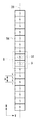
- FIG. 14 is a top view for explaining the magnetic field measurement apparatus according to the second embodiment
- FIG. 7 is a side view.
- 7 and 14 represents the pitch distance (2 mm in this embodiment) between the N pole and the S pole of the multipolar magnet.
- Reference numeral 56 denotes a 16-pole cuboid multipole magnet which is a position detection body, and also moves in the Y direction of the position detection body.
- the arrangement of the sensor units 8 and 9 and the 16-pole cuboid multipole magnet 59 shown in FIG. 14 is defined as a movement amount of 0 mm.
- the center of the magnetically sensitive part is installed in the vicinity of the straight line 20 formed by the midpoint of the side parallel to the x direction on the rectangular parallelepiped multipolar magnet 56.
- the magnetic fields perpendicular to the magnetosensitive surface applied to the Hall elements 1 (LL), 1 (LR), 1 (RL), and 1 (RR) are [ Equation 2].
- the voltage outputs V1 (LL), V1 (LR), V1 (RL) of the Hall elements 1 (LL), 1 (LR), 1 (RL), and 1 (RR), V1 (RR) is as shown in [Formula 3].
- V2, V3, V4, and V5 are obtained, [Formula 4] is obtained. Therefore, V (0) and V (90) as shown in FIG. 6 are obtained as [Equation 5].
- the threshold value of the hysteresis comparator is the same in the signal comparison unit 52a and the signal comparison unit 52b.
- movement information is added to the final pulse output that is output for each applied magnetic field period.
- a movement information signal from another output pin for example, if the movement direction is above the paper surface of FIG. 14.
- it can be implemented by outputting a High state and a Low state if it is below the page.
- the movement direction output when the movement direction output is not included in the output, it can be implemented by directly inputting the output value of the hysteresis comparator to the output section.
- the present invention can be implemented without any problem even in a magnetic field situation as shown in FIG.
- the sensor can process an applied magnetic field signal having a phase difference of 180 degrees by matching the magnet pitch and the center distance between the magnetic sensing portions of the sensor.
- a magnetic field as shown in [Equation 6] is applied to the center of the magnetic sensing part.
- V (0) and V (90) in the applied state are as shown in [Equation 7].
- the signal comparison units 52a and 52b, the comparison calculation unit 53, and the output shaping unit 54 in FIG. 6 are not based on analog processing or digital processing.
- the first subtraction block 61, the second subtraction block 62, the third subtraction block 63, the first addition block 71, the second addition block 72, and the fourth subtraction block 73 in FIG. As described above, the first to sixth addition / subtraction blocks 81 to 86 can be replaced.
- the direction of movement can be detected, and a magnetic field amplified by the magnetic flux collecting effect of the magnetic converging plate can be input to the Hall element.
- a magnetic field measurement device that realizes sensitivity and can effectively remove disturbance magnetic field (disturbance magnetic noise).
- Example 3 relates to a magnetic field measurement apparatus in the case where a rotation detection body (detection body) is a gear made of a magnetic body and is detected using a magnetoelectric conversion element.
- the sensor configuration for explaining the magnetic field measurement apparatus in the third embodiment is shown in FIG. 3, the side view for explaining the magnetic field measurement apparatus is shown in FIG. 15, and the block diagram for explaining the signal processing is shown in FIG. It is shown in In the third embodiment, the same constituent elements as those in the first embodiment are the same as those in the first embodiment except for the case where the constituent elements are particularly specified and described, and thus the description thereof is omitted.
- the gear tooth pitch C (the definition will be described later) and the magnetically sensitive part center distance B are made to coincide. This is arranged in such a manner that magnetic fields having a phase difference of 180 degrees are input to the centers of the magnetic sensing portions.
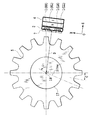
- FIG. 15 is a side view of the implementation style of the magnetic field measurement apparatus.
- reference numeral 5 denotes a 16-tooth gear made of a magnetic material
- reference C denotes a pitch distance of the concave and convex portions of the gear (by definition, the distance from the rotation center 18 to the midpoint of the magnetically sensitive parts 11 and 12 is D.
- D the distance from the rotation center 18 to the midpoint of the magnetically sensitive parts 11 and 12 is D.
- D the distance from the rotation center 18 to the midpoint of the magnetically sensitive parts 11 and 12
- D the distance from the rotation center 18 to the midpoint of the magnetically sensitive parts 11 and 12
- D the distance from the rotation center 18 to the midpoint of the magnetically sensitive parts 11 and 12
- D the distance from the rotation center 18 to the midpoint of the magnetically sensitive parts 11 and 12
- D the distance from the rotation center 18 to the midpoint of the magnetically sensitive parts 11 and 12 is D.
- D the distance from the rotation center 18 to the midpoint of the magnetically
- the line segment from the sensor surface and the rotation center 18 to the midpoint 21 of the center of each magnetic sensing portion is set substantially vertically.
- 4 is a back-bias magnet
- 17 is a rotating shaft of the rotated body
- ⁇ 1 is a rotation angle.
- the rotation axis is defined as being parallel to the Z axis and rotating about the rotation shaft center 18.
- the currently described diagram is defined as a rotation angle of 0 degree. In the third embodiment, it is assumed that the rotating shaft 17 rotates counterclockwise.
- each magnetically sensitive part is installed in the vicinity of the circumference (a circle having a radius D of the center 18) consisting of the middle point of the gear tooth thickness (Y-axis direction in FIG. 15).
- the magnetic field modulated by the back bias magnet and the gear teeth is not accompanied by the rotation of the gear teeth in the magnetic sensing part in the sensor unit 9 and the magnetic sensing part in the sensor unit 10 when there is no magnetic focusing plate. It can be approximated by a sine wave / cosine wave as in [Equation 1].
- the magnetic flux density described here is a case where there is no magnetic converging plate.
- the magnetic fields perpendicular to the magnetosensitive surface applied to the Hall elements 1 (LL), 1 (LR), 1 (RL), and 1 (RR) are [Equation 2], respectively. become that way.
- the deviation ⁇ from 180 degrees of the phase difference is a magnetic field in the x direction (horizontal direction) with respect to each sensor unit generated by the magnetic flux density of the back bias magnet 4 being modulated by the gear teeth 5. Occurs because it is not completely horizontal and is non-uniform, which occurs only in a magnetic field that is horizontal to the sensor surface. At this time, although a slight phase shift occurs even in a perpendicular magnetic field, it is very small, so it is ignored in this description.
- ⁇ is a constant determined by the arrangement including the size of the back bias magnet, the size of the magnetic converging plate, the size of the gear teeth, and the gap between them.
- V1 (RR) is as shown in [Formula 3].
- V2, V3, V4, and V5 are obtained by calculating the sum and difference of the voltage obtained in [Equation 3] by the signal processing of FIG. 6 as [Equation 4].
- V (0) and V (90) as shown in FIG. 6 are obtained as [Equation 5].
- the signal processing in the third embodiment is the same as the signal processing in the first embodiment.
- an ideal gear shape with uniform gear teeth shape is used, and an ideal sine or cosine wave magnetic field is applied to the sensor as the gear 5 rotates.
- the third embodiment can be implemented without any problem even in a magnetic field situation as shown in FIG.
- the sensor can process an applied magnetic field signal having a phase difference of 180 degrees by matching the magnet pitch and the center distance between the magnetic sensing portions of the sensor.
- a magnetic field such as [Equation 6] is applied to the center of the magnetic sensing part.
- ⁇ can be a phase difference caused by a mismatch between the magnetic field sensitive part center distance B of the sensor part and the gear tooth pitch C.
- the equation (19) is generated when the magnetic flux density of the back bias magnet 4 input to the sensor unit 9 is modulated by the gear teeth when the distance B between the magnetically sensitive parts and the gear tooth pitch C do not match.
- the magnetic field perpendicular to the sensor surface is expressed, and the equation (20) indicates that the magnetic flux density of the back bias magnet 4 input to the sensor unit 10 when the distance B between the magnetically sensitive parts and the gear tooth pitch C do not match.
- the magnetic field modulated by the gear teeth and representing the magnetic field perpendicular to the generated sensor surface, the formula (21) is input to the sensor unit 9 when the distance B between the magnetically sensitive parts and the gear tooth pitch C do not match.
- the magnetic flux density of the bias magnet 4 is modulated by the gear teeth, and represents the magnetic field horizontal to the generated sensor surface, and the equation (22) indicates that the distance between the center B of the magnetic sensor and the gear tooth pitch C does not match.
- the magnetic flux density of the magnet 4 is modulated by the gear teeth and represents a magnetic field horizontal to the resulting sensor surface.
- B′0 is the magnetic flux density of the back bias magnet 4 modulated by the gear teeth and the magnetic field amplitude perpendicular to the resulting sensor surface is B0 represents the magnetic field amplitude that is horizontal to the resulting sensor surface as the magnetic flux density of the back bias magnet 4 is modulated by the gear teeth.
- V (0) and V (90) in a state where such a magnetic field is applied is as shown in [Equation 7].
- the distance B between the centers of the magnetic field sensitive parts of the sensor unit and the gear tooth pitch is expressed in the form of multiplication by cosine.
- the above-described pitch phase can be used without any problem.
- each magnetic sensing portion is installed near the circumference (near the circle of radius D of the center 18) consisting of the middle point of the gear tooth thickness (Y-axis direction in FIG. 15). Even if the position of the center of the magnetic sensing part varies somewhat due to a deviation in the configuration, there is an adverse effect that the phase change and the input magnetic flux density amplitude that are raised in Equations (23) and (24) are reduced. Needless to say, there is no problem.
- the ring-shaped gear teeth have been described, but it is needless to say that shapes other than the ring-shaped gear teeth, such as a linearly moving gear (rack), can be used.
- the signal comparison units 52a and 52b, the comparison calculation unit 53, and the output shaping unit 54 in FIG. 6 are not based on analog processing or digital processing.
- the first subtraction block 61, the second subtraction block 62, the third subtraction block 63, the first addition block 71, the second addition block 72, and the fourth subtraction block 73 in FIG. As described above, the first to sixth addition / subtraction blocks 81 to 86 can be replaced.
- the back bias magnet described in this embodiment is preferably made of a material such as neodymium or samarium cobalt, but it goes without saying that it can also be used in a ferrite, an alnico magnet or the like.
- the magnetic flux converging plate is shaped as shown in FIG. 3, but it is needless to say that the shapes shown in FIGS. 16A to 16H and FIGS. 17A to 17C may be used.
- the distance between the centers of the magnetic sensing portions of the sensor portions in this embodiment, 2 mm
- the magnetization of the multipole magnet are described. That is, it is only necessary that the pitch roughly matches, that is, the present invention can be implemented regardless of the number of poles.
- the rotation direction can be detected, and a magnetic field amplified by the magnetic flux collecting effect of the magnetic converging plate can be input to the Hall element.
- the high S / N reduces the output jitter and increases the sensor sensitivity.
- a gear tooth rotation detector that can effectively eliminate disturbance magnetic field (disturbance magnetic noise) has been proposed.
Abstract
Description
本実施例1は、被回転検出体が多極リング磁石であり磁電変換素子にホール素子を用いて検出する場合の磁場計測装置に関するものである。なお、本実施例1における磁場計測装置を説明するためのセンサ構成は図3に示され、磁場計測装置を説明するための上面図は図8、側面図は図7、信号処理を説明するためのブロック図は図6、図18である。 Example 1
The first embodiment relates to a magnetic field measuring apparatus in the case where the rotation detection body is a multipolar ring magnet and the magnetoelectric conversion element is detected using a Hall element. The sensor configuration for explaining the magnetic field measurement apparatus in the first embodiment is shown in FIG. 3, the top view for explaining the magnetic field measurement apparatus is FIG. 8, the side view is FIG. 7, and the signal processing is explained. FIG. 6 and FIG. 18 are block diagrams.
1(LL)は左部センサ部9内の第1のホール素子、1(LR)は左部センサ部9内の第2のホール素子、1(RL)は右部センサ部10内の第3のホール素子、1(RR)は右部センサ部10内の第4のホール素子、7は磁性体から構成される磁気収束板、8はシリコン基板、11は左部センサ部における磁気感磁部中心、12は右部センサ部における磁気感磁部中心、符号Bは左右の磁気感磁部中心間の距離(本実施例では2mm)を表わす。第1のホール素子から第4のホール素子は、ホール素子の感磁面の法線方向(感磁面の方向)が略同一となるように配置されている。 The detailed sensor configuration is as follows.
1 (LL) is the first Hall element in the


信号増幅部51はある所定の出力付近まで入力波形を増幅するオートゲインコントロール機能を有した信号増幅部である。信号比較部52はコンパレータのチャタリングを防ぎながら、アナログ入力波形をデジタルパルス出力とするためのヒステリシスコンパレータなどで構成される信号比較部である。信号演算部53は信号比較部52の一方の出力の立ち上がり或いは立ち下がりエッジを検出した際に、他方の出力状態を観測し回転方向を判定可能な機能を有しており、出力として、2値の回転方向情報とエッジ切り替わりのタイミング情報を持つ。出力成型部54は信号演算部53の出力をもとに出力パルス波形を作り出す。出力部55はドライバである。 Next, specific signal processing of the obtained signals V (0) and V (90) will be described.
The signal amplifying unit 51 is a signal amplifying unit having an auto gain control function for amplifying an input waveform up to a certain predetermined output. The signal comparison unit 52 is a signal comparison unit configured by a hysteresis comparator or the like for converting an analog input waveform into a digital pulse output while preventing chattering of the comparator. The
第3の減算ブロック及び第4の減算ブロックの出力までで得られた式(17)、式(18)に示されるV(0)、V(90)の信号をそれぞれ信号増幅部51a,51bに入力し、増幅された出力信号を図10Aのように、それぞれヒステリシス付きコンパレータ(信号比較部)に入力し、図10Bのように比較後の信号を出力する。ここで図10BのVref1、Vref2はヒステリシスコンパレータの閾値である。ここでヒステリシスコンパレータを用いた理由は、ヒステリシスを設けることにより回路ノイズによる出力のチャタリングを防ぐ為である。 Next, signal processing will be described using the signal flow of FIG.
The signals of V (0) and V (90) shown in the equations (17) and (18) obtained up to the outputs of the third subtraction block and the fourth subtraction block are respectively sent to the


V(0)=(E-F)-(G-H) ・・・(25)
V(0)=(E-F)+(H-G)
=(E-G)+(H-F)
=(E-G)-(F-H)
=(E+H)-(F+G)
=(E-F-G+H) ・・・(26)
ここで、例えば、EとFの和がEと(-F)の差と表現できるように、和と差に実質的な違いはない。従って、式(26)をさらに変形すれば、V(0)は例えば式(27)で表すことができる。
V(0)=(E+(-F))+(H+(-G))
=(E+(-G))+(H+(-F))
=(E+(-G))-(F+(-H))
=(E-(-H))-(F-(-G))
=(E+(-F)+(-G)+H) ・・・(27)
そのため、式(25)ないし式(27)を用いれば、V(0)を、E及びFを加減算した結果とG及びHを加減算した結果とを加減算した結果であると表現することも可能である。また、V(0)を、E及びGを加減算した結果とF及びHを加減算した結果とを加減算した結果と表現することも可能である。同様に、V(0)を、E及びHを加減算した結果とF及びGを加減算した結果とを加減算した結果と表現することも可能であり、又、V(0)を、EとFとGとHとを加減算した結果と表現することも可能である。 By the way, when V1 (LL) = E, V1 (LR) = F, V1 (RL) = G, and V1 (RR) = H, the equation (17) can be expressed by the following equation (25). Furthermore, if Formula (25) is deform | transformed, V (0) can be represented by Formula (26), for example.
V (0) = (EF) − (GH) (25)
V (0) = (E−F) + (HG)
= (EG) + (HF)
= (EG)-(FH)
= (E + H)-(F + G)
= (E−F−G + H) (26)
Here, for example, there is no substantial difference between the sum and the difference so that the sum of E and F can be expressed as a difference between E and (−F). Therefore, if Formula (26) is further modified, V (0) can be expressed by Formula (27), for example.
V (0) = (E + (− F)) + (H + (− G))
= (E + (-G)) + (H + (-F))
= (E + (-G))-(F + (-H))
= (E-(-H))-(F-(-G))
= (E + (− F) + (− G) + H) (27)
Therefore, using Expressions (25) to (27), V (0) can also be expressed as the result of adding and subtracting the result of adding and subtracting E and F and the result of adding and subtracting G and H. is there. Further, V (0) can be expressed as a result of adding / subtracting the result of adding / subtracting E and G and the result of adding / subtracting F / H. Similarly, V (0) can be expressed as the result of adding / subtracting the result of adding / subtracting E and H and the result of adding / subtracting F / G, and V (0) can be expressed as E and F. It can also be expressed as the result of adding and subtracting G and H.
本発明に係る実施例2は、被位置検出体(被検出体)の位置を磁電変換素子を用いて検出する磁場計測装置に関するものである。なお、本実施例2における磁場計測装置を説明するためのセンサ構成は、上述した図3、磁場計測装置を説明するための上面図は図14、側面図は図7、信号処理を説明するためのブロック図は図6に示してある。実施例2において、実施例1と同様の構成要素については、その構成要素について特に指定して説明した場合を除いて実施例1と同様であるため、その説明を省略する。 (Example 2)
Example 2 which concerns on this invention is related with the magnetic field measuring device which detects the position of a to-be-detected body (detected body) using a magnetoelectric conversion element. The sensor configuration for explaining the magnetic field measuring apparatus in the second embodiment is the above-described FIG. 3, the top view for explaining the magnetic field measuring apparatus is FIG. 14, the side view is FIG. 7, and the signal processing is explained. This block diagram is shown in FIG. In the second embodiment, the same constituent elements as those in the first embodiment are the same as those in the first embodiment except for the case where the constituent elements are particularly specified and described, and thus the description thereof is omitted.
本発明に係る実施例3は、被回転検出体(被検出体)が磁性体からなるギアであり、磁電変換素子を用いて検出する場合の磁場計測装置に関するものである。なお、本実施例3における磁場計測装置を説明するためのセンサ構成は、上述した図3、磁場計測装置を説明するための側面図は図15、信号処理を説明するためのブロック図は図6に示してある。実施例3において、実施例1と同様の構成要素については、その構成要素について特に指定して説明した場合を除いて実施例1と同様であるため、その説明を省略する。 (Example 3)
Example 3 according to the present invention relates to a magnetic field measurement apparatus in the case where a rotation detection body (detection body) is a gear made of a magnetic body and is detected using a magnetoelectric conversion element. The sensor configuration for explaining the magnetic field measurement apparatus in the third embodiment is shown in FIG. 3, the side view for explaining the magnetic field measurement apparatus is shown in FIG. 15, and the block diagram for explaining the signal processing is shown in FIG. It is shown in In the third embodiment, the same constituent elements as those in the first embodiment are the same as those in the first embodiment except for the case where the constituent elements are particularly specified and described, and thus the description thereof is omitted.
図15は、本磁場計測装置の実施様式側面図である。図15中符号5は磁性体からなる16歯ギアであり、符号Cはギアの凹凸のピッチ距離(定義としては回転中心18から磁気感磁部中心11、12の中点までの距離をDとした際にギア5の電気角1周期、すなわち機械角22.5度を用いて、D×tan(22.5/2)で表わされる。本実施例のギアではCは2mm)を表わす。また、センサ面と回転中心18からそれぞれの磁気感磁部中心の中点21までの線分は略垂直に設置される。4はバックバイアス磁石、17は被回転体の回転シャフト、また、θ1は回転角である。なお回転軸はZ軸に平行であり、回転シャフト中心18に回転すると定義する。また、現在表記している図は回転角度0度と定義する。実施例3では、回転シャフト17は反時計まわりに回転するものとする。 Next, FIG. 15 which is a drawing of the implementation style of the magnetic field measurement apparatus will be described in detail.
FIG. 15 is a side view of the implementation style of the magnetic field measurement apparatus. In FIG. 15,
Claims (15)
- 磁場発生体から発生する磁場の強度を検出する磁場計測装置であって、
第1から第4の磁電変換素子と、
磁性体からなる磁気収束板と、
前記磁電変換素子の感磁面に対して水平方向及び/又は垂直方向に印加される磁場の強度を算出する算出部と、
を備え、
前記磁気収束板は、
前記第1の磁電変換素子の感磁面と前記第2の磁電変換素子の感磁面に対して水平方向に発生する磁場ベクトルを前記第1の磁電変換素子の感磁面と第2の磁電変換素子の感磁面に対して垂直方向且つそれぞれの感磁面で逆方向の磁場ベクトルに変換し、更に、
前記第3の磁電変換素子の感磁面と前記第4の磁電変換素子の感磁面に対して水平方向に発生する磁場ベクトルを前記第3の磁電変換素子の感磁面と第4の磁電変換素子の感磁面に対して垂直方向且つそれぞれの感磁面で逆方向の磁場ベクトルに変換するように前記第1から第4の磁電変換素子の近傍に配置されており、
前記算出部は、前記第1から第4の磁電変換素子の出力を加減算し、算出結果を出力する第1の算出ブロックを有することを特徴とする磁場計測装置。 A magnetic field measuring device for detecting the intensity of a magnetic field generated from a magnetic field generator,
First to fourth magnetoelectric transducers;
A magnetic converging plate made of a magnetic material;
A calculation unit for calculating the strength of a magnetic field applied in a horizontal direction and / or a vertical direction with respect to a magnetic sensitive surface of the magnetoelectric conversion element;
With
The magnetic converging plate is
A magnetic field vector generated in a horizontal direction with respect to the magnetosensitive surface of the first magnetoelectric transducer and the magnetosensitive surface of the second magnetoelectric transducer is expressed as the magnetosensitive surface of the first magnetoelectric transducer and the second magnetoelectric. Convert to a magnetic field vector perpendicular to the magnetic sensing surface of the conversion element and in the opposite direction at each magnetic sensing surface,
A magnetic field vector generated in a horizontal direction with respect to the magnetosensitive surface of the third magnetoelectric transducer and the magnetosensitive surface of the fourth magnetoelectric transducer is defined as the magnetosensitive surface of the third magnetoelectric transducer and the fourth magnetoelectric. It is arranged in the vicinity of the first to fourth magnetoelectric transducers so as to convert the magnetic field vector in the direction perpendicular to the magnetic sensitive surface of the conversion element and in the opposite direction at each magnetic sensitive surface,
The magnetic field measurement apparatus, wherein the calculation unit includes a first calculation block that adds and subtracts outputs of the first to fourth magnetoelectric transducers and outputs a calculation result. - 磁場発生体から発生する磁場の強度を検出する磁場計測装置であって、
第1から第4の磁電変換素子と、
前記磁電変換素子の感磁面に対して水平方向及び/又は垂直方向に印加される磁場の強度を算出する算出部と、
を備え、
前記算出部は、
前記第1から第4の磁電変換素子の出力を加減算し、算出結果を出力する第1の算出ブロックと、
前記第1から第4の磁電変換素子の出力を加減算して前記第1の算出ブロックの出力信号と位相が90度異なる信号を算出し、算出結果を出力する第2の算出ブロックと、
を備えることを特徴とする磁場計測装置。 A magnetic field measuring device for detecting the intensity of a magnetic field generated from a magnetic field generator,
First to fourth magnetoelectric transducers;
A calculation unit for calculating the strength of a magnetic field applied in a horizontal direction and / or a vertical direction with respect to a magnetic sensitive surface of the magnetoelectric conversion element;
With
The calculation unit includes:
A first calculation block for adding and subtracting outputs of the first to fourth magnetoelectric transducers and outputting a calculation result;
A second calculation block for calculating a signal whose phase differs from that of the output signal of the first calculation block by adding / subtracting the outputs of the first to fourth magnetoelectric transducers, and outputting a calculation result;
A magnetic field measurement apparatus comprising: - 前記第1の算出ブロックは、前記第1の磁電変換素子と前記第2の磁電変換素子の出力を加減算し、算出結果を出力する第1の加減算ブロックと、前記第3の磁電変換素子と前記第4の磁電変換素子の出力を加減算し、算出結果を出力する第2の加減算ブロックと、前記第1の加減算ブロックの出力と前記第2の加減算ブロックの出力を加減算し、算出結果を出力する第3の加減算ブロックと、を備えることを特徴とする請求項1又は2に記載の磁場計測装置。 The first calculation block adds / subtracts outputs of the first magnetoelectric conversion element and the second magnetoelectric conversion element, and outputs a calculation result; the third magnetoelectric conversion element; Addition / subtraction of the output of the fourth magnetoelectric transducer, and addition / subtraction of the output of the first addition / subtraction block and the output of the second addition / subtraction block, which outputs the calculation result, and outputs the calculation result The magnetic field measurement apparatus according to claim 1, further comprising a third addition / subtraction block.
- 前記第1の算出ブロックは、前記第1の磁電変換素子と前記第3の磁電変換素子の出力を加減算し、算出結果を出力する第1の加減算ブロックと、前記第2の磁電変換素子と前記第4の磁電変換素子の出力を加減算し、算出結果を出力する第2の加減算ブロックと、前記第1の加減算ブロックの出力と前記第2の加減算ブロックの出力を加減算し、算出結果を出力する第3の加減算ブロックと、を備えることを特徴とする請求項1又は2に記載の磁場計測装置。 The first calculation block adds / subtracts outputs of the first magnetoelectric conversion element and the third magnetoelectric conversion element and outputs a calculation result; the second magnetoelectric conversion element; Addition / subtraction of the output of the fourth magnetoelectric transducer, and addition / subtraction of the output of the first addition / subtraction block and the output of the second addition / subtraction block, which outputs the calculation result, and outputs the calculation result The magnetic field measurement apparatus according to claim 1, further comprising a third addition / subtraction block.
- 前記算出部は、前記第1から第4の磁電変換素子の出力を加減算し、前記第1の算出ブロックの出力信号と位相が異なる信号を算出する第2の算出ブロックを有することを特徴とする請求項1乃至4のいずれかに記載の磁場計測装置。 The calculation unit includes a second calculation block that adds and subtracts the outputs of the first to fourth magnetoelectric transducers to calculate a signal having a phase different from that of the output signal of the first calculation block. The magnetic field measuring apparatus according to claim 1.
- 前記第1の算出ブロックの出力信号と前記第2の算出ブロックの出力信号との位相差は、90度であることを特徴とする請求項5に記載の磁場計測装置。 The magnetic field measurement apparatus according to claim 5, wherein the phase difference between the output signal of the first calculation block and the output signal of the second calculation block is 90 degrees.
- 前記第2の算出ブロックは、前記第1の磁電変換素子と前記第2の磁電変換素子の出力を加減算し、算出結果を出力する第4の加減算ブロックと、前記第3の磁電変換素子と前記第4の磁電変換素子の出力を加減算し、算出結果を出力する第5の加減算ブロックと、前記第4の加減算ブロックの出力と前記第5の加減算ブロックの出力を加減算し、算出結果を出力する第6の加減算ブロックと、を備えることを特徴とする請求項5又は6に記載の磁場計測装置。 The second calculation block adds and subtracts the outputs of the first and second magnetoelectric conversion elements and outputs a calculation result; the third magnetoelectric conversion element; and A fifth addition / subtraction block that adds and subtracts the output of the fourth magnetoelectric transducer and outputs a calculation result, and adds and subtracts the output of the fourth addition / subtraction block and the output of the fifth addition / subtraction block, and outputs the calculation result. The magnetic field measurement apparatus according to claim 5, further comprising a sixth addition / subtraction block.
- 前記第2の算出ブロックは、前記第1の磁電変換素子と前記第3の磁電変換素子の出力を加減算し、算出結果を出力する第4の加減算ブロックと、前記第2の磁電変換素子と前記第4の磁電変換素子の出力を加減算し、算出結果を出力する第5の加減算ブロックと、前記第4の加減算ブロックの出力と前記第5の加減算ブロックの出力を加減算し、算出結果を出力する第6の加減算ブロックと、を備えることを特徴とする請求項5又は6に記載の磁場計測装置。 The second calculation block includes a fourth addition / subtraction block that adds and subtracts outputs of the first magnetoelectric conversion element and the third magnetoelectric conversion element and outputs a calculation result; the second magnetoelectric conversion element; A fifth addition / subtraction block that adds and subtracts the output of the fourth magnetoelectric transducer and outputs a calculation result, and adds and subtracts the output of the fourth addition / subtraction block and the output of the fifth addition / subtraction block, and outputs the calculation result. The magnetic field measurement apparatus according to claim 5, further comprising a sixth addition / subtraction block.
- 前記第1から第4の磁電変換素子が略直線状に配置されていることを特徴とする請求項1乃至8のいずれかに記載の磁場計測装置。 The magnetic field measuring apparatus according to any one of claims 1 to 8, wherein the first to fourth magnetoelectric transducers are arranged substantially linearly.
- 前記算出部は、前記磁場発生体の位置、移動又は回転を検知することを特徴とする請求項1乃至9のいずれかに記載の磁場計測装置。 10. The magnetic field measurement apparatus according to claim 1, wherein the calculation unit detects the position, movement, or rotation of the magnetic field generator.
- 前記算出部は、前記第1の算出ブロックの出力に基づいて、前記磁場発生体の位置、移動又は回転を検知することを特徴とする請求項10に記載の磁場計測装置。 The magnetic field measurement apparatus according to claim 10, wherein the calculation unit detects the position, movement, or rotation of the magnetic field generator based on an output of the first calculation block.
- 前記算出部は、前記第1の算出ブロックの出力信号をパルス波形に成形した信号に基づいて、前記磁場発生体の位置、移動又は回転を検知することを特徴とする請求項10又は11に記載の磁場計測装置。 The said calculation part detects the position of the said magnetic field generator, a movement, or rotation based on the signal which shape | molded the output signal of the said 1st calculation block into the pulse waveform, The Claim 10 or 11 characterized by the above-mentioned. Magnetic field measurement device.
- 前記算出部は、前記第1の算出ブロックの出力と、前記第2の算出ブロックの出力と、に基づいて、前記磁場発生体の位置、移動又は回転を検知することを特徴とする請求項5乃至8のいずれかに記載の磁場計測装置。 The said calculation part detects the position of the said magnetic field generator, a movement, or rotation based on the output of a said 1st calculation block, and the output of a said 2nd calculation block, The said calculation part is characterized by the above-mentioned. The magnetic field measurement apparatus in any one of thru | or 8.
- 磁場発生体を備え、
該磁場発生体が移動可能及び/又は回転可能な多極着磁された磁石、又は、前記第1から第4の磁電変換素子の近傍に設置されたバックバイアス磁石と、移動可能及び/又は回転可能なギヤ歯から構成される構成体であることを特徴とする請求項1乃至13のいずれかに記載の磁場計測装置。 With a magnetic field generator,
The magnetic field generator is movable and / or rotatable multipolar magnetized magnets, or back bias magnets installed in the vicinity of the first to fourth magnetoelectric transducers, and movable and / or rotated. The magnetic field measuring apparatus according to claim 1, wherein the magnetic field measuring apparatus is a structure including possible gear teeth. - 磁場発生体を備え、
該磁場発生体が前記第1から第4の磁電変換素子の近傍に設置されたバックバイアス磁石と、移動可能及び/又は回転可能なギヤ歯から構成される構成体であり、
前記第1から第4の磁電変換素子は、前記バックバイアス磁石と前記ギヤ歯に挟まれる位置に配置されることを特徴とする請求項1乃至13のいずれかに記載の磁場計測装置。 With a magnetic field generator,
The magnetic field generator comprises a back bias magnet installed in the vicinity of the first to fourth magnetoelectric transducers and movable and / or rotatable gear teeth;
14. The magnetic field measurement apparatus according to claim 1, wherein the first to fourth magnetoelectric transducers are arranged at positions sandwiched between the back bias magnet and the gear teeth.
Priority Applications (4)
| Application Number | Priority Date | Filing Date | Title |
|---|---|---|---|
| US14/233,411 US9581426B2 (en) | 2011-07-29 | 2012-07-27 | Magnetic field measuring device |
| EP12820604.2A EP2738563B1 (en) | 2011-07-29 | 2012-07-27 | Magnetic field measuring device |
| CN201280038311.6A CN103718056B (en) | 2011-07-29 | 2012-07-27 | Magnetic field measuring device |
| JP2013526754A JP5629007B2 (en) | 2011-07-29 | 2012-07-27 | Magnetic field measuring device |
Applications Claiming Priority (2)
| Application Number | Priority Date | Filing Date | Title |
|---|---|---|---|
| JP2011-166635 | 2011-07-29 | ||
| JP2011166635 | 2011-07-29 |
Publications (1)
| Publication Number | Publication Date |
|---|---|
| WO2013018347A1 true WO2013018347A1 (en) | 2013-02-07 |
Family
ID=47628898
Family Applications (1)
| Application Number | Title | Priority Date | Filing Date |
|---|---|---|---|
| PCT/JP2012/004813 WO2013018347A1 (en) | 2011-07-29 | 2012-07-27 | Magnetic field measuring device |
Country Status (5)
| Country | Link |
|---|---|
| US (1) | US9581426B2 (en) |
| EP (1) | EP2738563B1 (en) |
| JP (2) | JP5629007B2 (en) |
| CN (1) | CN103718056B (en) |
| WO (1) | WO2013018347A1 (en) |
Cited By (4)
| Publication number | Priority date | Publication date | Assignee | Title |
|---|---|---|---|---|
| CN103558565A (en) * | 2013-10-14 | 2014-02-05 | 中国科学院电工研究所 | Three-leg type magnetic field detection robot |
| JP2018517123A (en) * | 2015-04-09 | 2018-06-28 | インターナショナル・ビジネス・マシーンズ・コーポレーションInternational Business Machines Corporation | Rotating magnetic field Hall device, method of operating a rotating magnetic field Hall device, and computing system |
| JP2019190872A (en) * | 2018-04-19 | 2019-10-31 | 日本電産サンキョー株式会社 | Encoder |
| WO2020241577A1 (en) * | 2019-05-27 | 2020-12-03 | 株式会社デンソー | Motor |
Families Citing this family (17)
| Publication number | Priority date | Publication date | Assignee | Title |
|---|---|---|---|---|
| JP6353380B2 (en) * | 2015-02-24 | 2018-07-04 | メレキシス テクノロジーズ エス エー | Rotation detector |
| US20160321810A1 (en) * | 2015-04-28 | 2016-11-03 | Pixart Imaging (Penang) Sdn. Bhd. | Optical navigation sensor, electronic device with optical navigation function and operation method thereof |
| US10139214B2 (en) * | 2015-09-07 | 2018-11-27 | Electronics And Telecommunications Research Institute | Apparatus for acquiring location coordinates of object using two measurement heads and method using the same |
| US9976876B2 (en) | 2015-11-24 | 2018-05-22 | Allegro Microsystems, Llc | Methods and apparatus for phase selection in ring magnet sensing |
| JP6566885B2 (en) * | 2016-02-10 | 2019-08-28 | メレキシス テクノロジーズ エス エー | Rotation detector |
| US10093349B2 (en) * | 2016-03-02 | 2018-10-09 | Trw Automotive U.S. Llc | Monitoring of an electric motor in an electric power steering assembly |
| JP6934708B2 (en) * | 2016-07-20 | 2021-09-15 | メレキシス テクノロジーズ エス エーMelexis Technologies SA | Displacement detector |
| JP6449819B2 (en) * | 2016-07-23 | 2019-01-09 | メレキシス テクノロジーズ エス エー | Displacement detection device and continuously variable transmission |
| JP6555289B2 (en) * | 2017-03-13 | 2019-08-07 | 株式会社デンソー | Rotation sensor |
| EP3470861B1 (en) | 2017-10-10 | 2019-11-27 | Melexis Technologies SA | Redundant sensor fault detection |
| EP3502628B1 (en) | 2017-12-21 | 2020-07-29 | Melexis Technologies SA | Redundant combinatory readout |
| EP3531151B1 (en) | 2018-02-27 | 2020-04-22 | Melexis Technologies SA | Redundant sensor error reduction |
| CN108776314A (en) * | 2018-04-18 | 2018-11-09 | 微传智能科技(常州)有限公司 | ASIC processing circuits, offset voltage and low-frequency noise removal circuit, threshold decision circuit |
| JP6973421B2 (en) * | 2019-01-14 | 2021-11-24 | 株式会社デンソー | Rotation detector |
| WO2020170771A1 (en) * | 2019-02-18 | 2020-08-27 | XELA・Robotics株式会社 | Magnetic sensing system, detection device, and magnetic interference offset method |
| US11808610B2 (en) | 2021-02-09 | 2023-11-07 | Asahi Kasei Microdevices Corporation | Position detection apparatus, position detection system, and position detection method |
| US11719525B2 (en) * | 2021-10-20 | 2023-08-08 | Renesas Electronics America Inc. | Adaptive position detection for inductive linear position sensing |
Citations (5)
| Publication number | Priority date | Publication date | Assignee | Title |
|---|---|---|---|---|
| JP2003294818A (en) * | 2002-03-28 | 2003-10-15 | Asahi Kasei Corp | Magnetometric sensor and method of manufacturing the same |
| JP2008304470A (en) * | 2008-07-10 | 2008-12-18 | Asahi Kasei Electronics Co Ltd | Magnetic sensor |
| JP2009150732A (en) | 2007-12-19 | 2009-07-09 | Asahi Kasei Electronics Co Ltd | Position detection device |
| WO2010008465A1 (en) * | 2008-06-24 | 2010-01-21 | Magic Technologies, Inc. | Gear tooth sensor (gts) with magnetoresistive bridge |
| JP2011508891A (en) * | 2008-01-04 | 2011-03-17 | アレグロ・マイクロシステムズ・インコーポレーテッド | Method and apparatus for angle sensor |
Family Cites Families (10)
| Publication number | Priority date | Publication date | Assignee | Title |
|---|---|---|---|---|
| US6097183A (en) * | 1998-04-14 | 2000-08-01 | Honeywell International Inc. | Position detection apparatus with correction for non-linear sensor regions |
| JP4936299B2 (en) | 2000-08-21 | 2012-05-23 | メレクシス・テクノロジーズ・ナムローゼフェンノートシャップ | Magnetic field direction detection sensor |
| EP1243897B1 (en) | 2001-03-23 | 2013-12-18 | Melexis Technologies NV | Magnetic position sensor |
| CN1330939C (en) * | 2002-03-22 | 2007-08-08 | 旭化成电子材料元件株式会社 | Angle determining apparatus and angle determining system |
| JP2004257995A (en) * | 2003-02-27 | 2004-09-16 | Asahi Kasei Electronics Co Ltd | 3-dimensional magnetism sensing device and semiconductor device |
| EP1772737A3 (en) * | 2005-10-08 | 2008-02-20 | Melexis Technologies SA | Assembly group for the current measurement |
| JP5131537B2 (en) * | 2007-04-25 | 2013-01-30 | アイシン精機株式会社 | Angle detector |
| JP2009192261A (en) * | 2008-02-12 | 2009-08-27 | Aisin Seiki Co Ltd | Rectilinear displacement detector |
| JP2011059103A (en) | 2009-08-11 | 2011-03-24 | Asahi Kasei Electronics Co Ltd | Rotational angle detector, position detector, and detection method of the same |
| JP5013146B2 (en) | 2009-12-03 | 2012-08-29 | Tdk株式会社 | Magnetic position detector |
-
2012
- 2012-07-27 CN CN201280038311.6A patent/CN103718056B/en active Active
- 2012-07-27 JP JP2013526754A patent/JP5629007B2/en active Active
- 2012-07-27 WO PCT/JP2012/004813 patent/WO2013018347A1/en active Application Filing
- 2012-07-27 EP EP12820604.2A patent/EP2738563B1/en active Active
- 2012-07-27 US US14/233,411 patent/US9581426B2/en active Active
-
2014
- 2014-04-07 JP JP2014079010A patent/JP5853046B2/en active Active
Patent Citations (5)
| Publication number | Priority date | Publication date | Assignee | Title |
|---|---|---|---|---|
| JP2003294818A (en) * | 2002-03-28 | 2003-10-15 | Asahi Kasei Corp | Magnetometric sensor and method of manufacturing the same |
| JP2009150732A (en) | 2007-12-19 | 2009-07-09 | Asahi Kasei Electronics Co Ltd | Position detection device |
| JP2011508891A (en) * | 2008-01-04 | 2011-03-17 | アレグロ・マイクロシステムズ・インコーポレーテッド | Method and apparatus for angle sensor |
| WO2010008465A1 (en) * | 2008-06-24 | 2010-01-21 | Magic Technologies, Inc. | Gear tooth sensor (gts) with magnetoresistive bridge |
| JP2008304470A (en) * | 2008-07-10 | 2008-12-18 | Asahi Kasei Electronics Co Ltd | Magnetic sensor |
Non-Patent Citations (1)
| Title |
|---|
| See also references of EP2738563A4 |
Cited By (7)
| Publication number | Priority date | Publication date | Assignee | Title |
|---|---|---|---|---|
| CN103558565A (en) * | 2013-10-14 | 2014-02-05 | 中国科学院电工研究所 | Three-leg type magnetic field detection robot |
| JP2018517123A (en) * | 2015-04-09 | 2018-06-28 | インターナショナル・ビジネス・マシーンズ・コーポレーションInternational Business Machines Corporation | Rotating magnetic field Hall device, method of operating a rotating magnetic field Hall device, and computing system |
| JP2019190872A (en) * | 2018-04-19 | 2019-10-31 | 日本電産サンキョー株式会社 | Encoder |
| JP7114315B2 (en) | 2018-04-19 | 2022-08-08 | 日本電産サンキョー株式会社 | encoder |
| WO2020241577A1 (en) * | 2019-05-27 | 2020-12-03 | 株式会社デンソー | Motor |
| JPWO2020241577A1 (en) * | 2019-05-27 | 2021-10-14 | 株式会社デンソー | motor |
| JP7211504B2 (en) | 2019-05-27 | 2023-01-24 | 株式会社デンソー | motor |
Also Published As
| Publication number | Publication date |
|---|---|
| EP2738563A4 (en) | 2015-05-06 |
| JP2014145777A (en) | 2014-08-14 |
| US9581426B2 (en) | 2017-02-28 |
| US20140156220A1 (en) | 2014-06-05 |
| CN103718056A (en) | 2014-04-09 |
| EP2738563A1 (en) | 2014-06-04 |
| CN103718056B (en) | 2016-08-17 |
| EP2738563B1 (en) | 2017-08-30 |
| JP5853046B2 (en) | 2016-02-09 |
| JPWO2013018347A1 (en) | 2015-03-05 |
| JP5629007B2 (en) | 2014-11-19 |
Similar Documents
| Publication | Publication Date | Title |
|---|---|---|
| JP5853046B2 (en) | Magnetic field measuring device | |
| US11592318B2 (en) | Arrangement, method and sensor for measuring an absolute angular position using a multi-pole magnet | |
| JP5245114B2 (en) | Position detection device | |
| JP5056890B2 (en) | Stroke amount detection device | |
| US8664943B2 (en) | Position detecting apparatus | |
| Wu et al. | A rotary encoder with an eccentrically mounted ring magnet | |
| US9182249B2 (en) | Rotation angle detection device | |
| US8566063B2 (en) | Rotation angle detector | |
| JP5105200B2 (en) | Angle detection apparatus and angle detection method | |
| JP5613839B2 (en) | Method and apparatus for absolute positioning of a moving object | |
| JP5408508B2 (en) | Position detection device | |
| EP3735569A1 (en) | Magnetic field influence during rotation movement of magnetic target | |
| JP2008151774A (en) | Rotation angle detector and rotating machine | |
| CN110418942B (en) | Rotary sensor | |
| JPWO2007055135A1 (en) | Magnetic encoder device | |
| JP5002917B2 (en) | Rotation angle detector | |
| JP2015087213A (en) | Magnetic encoder | |
| JP5050817B2 (en) | Magnetic encoder | |
| JP2013160711A (en) | Position detection device |
Legal Events
| Date | Code | Title | Description |
|---|---|---|---|
| 121 | Ep: the epo has been informed by wipo that ep was designated in this application |
Ref document number: 12820604 Country of ref document: EP Kind code of ref document: A1 |
|
| ENP | Entry into the national phase |
Ref document number: 2013526754 Country of ref document: JP Kind code of ref document: A |
|
| WWE | Wipo information: entry into national phase |
Ref document number: 14233411 Country of ref document: US |
|
| REEP | Request for entry into the european phase |
Ref document number: 2012820604 Country of ref document: EP |
|
| NENP | Non-entry into the national phase |
Ref country code: DE |