WO2013015324A1 - 電子機器 - Google Patents
電子機器 Download PDFInfo
- Publication number
- WO2013015324A1 WO2013015324A1 PCT/JP2012/068856 JP2012068856W WO2013015324A1 WO 2013015324 A1 WO2013015324 A1 WO 2013015324A1 JP 2012068856 W JP2012068856 W JP 2012068856W WO 2013015324 A1 WO2013015324 A1 WO 2013015324A1
- Authority
- WO
- WIPO (PCT)
- Prior art keywords
- housing
- electronic device
- vibration
- housing portion
- movable
- Prior art date
- Legal status (The legal status is an assumption and is not a legal conclusion. Google has not performed a legal analysis and makes no representation as to the accuracy of the status listed.)
- Ceased
Links
Images







Classifications
-
- B—PERFORMING OPERATIONS; TRANSPORTING
- B06—GENERATING OR TRANSMITTING MECHANICAL VIBRATIONS IN GENERAL
- B06B—METHODS OR APPARATUS FOR GENERATING OR TRANSMITTING MECHANICAL VIBRATIONS OF INFRASONIC, SONIC, OR ULTRASONIC FREQUENCY, e.g. FOR PERFORMING MECHANICAL WORK IN GENERAL
- B06B1/00—Methods or apparatus for generating mechanical vibrations of infrasonic, sonic, or ultrasonic frequency
- B06B1/02—Methods or apparatus for generating mechanical vibrations of infrasonic, sonic, or ultrasonic frequency making use of electrical energy
- B06B1/04—Methods or apparatus for generating mechanical vibrations of infrasonic, sonic, or ultrasonic frequency making use of electrical energy operating with electromagnetism
- B06B1/045—Methods or apparatus for generating mechanical vibrations of infrasonic, sonic, or ultrasonic frequency making use of electrical energy operating with electromagnetism using vibrating magnet, armature or coil system
Definitions
- the present invention relates to an electronic device.
- This application claims priority based on Japanese Patent Application No. 2011-164310 for which it applied on July 27, 2011, and uses the content here.
- Patent Document 1 As an electronic device such as a mobile phone or a portable information terminal, for example, a technique described in Patent Document 1 is known.
- a configuration that allows a user to detect vibration may be used.
- a vibration generator for generating such vibration for example, a vibration motor is known.
- a vibration motor for example, a configuration in which a weight is attached to the tip of a cylindrical rotor and vibration is generated by the rotation of the rotor is known.
- the conventional vibration generator is configured to transmit vibration to the housing via the motor, there may be a case where vibration is not sufficiently transmitted to the outside.
- An object of an aspect of the present invention is to provide an electronic device that can efficiently transmit vibration to the outside.
- a housing having an electronic circuit and having a first housing portion and a second housing portion, and vibrating in a predetermined direction, the first housing portion and the second housing portion.
- An electronic device in which at least a part of at least one of the first housing part and the second housing part is exposed to the outside.
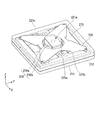
- FIG. 11 is a diagram illustrating a partial configuration of an electronic apparatus according to the embodiment.
- FIG. 11 is a diagram illustrating a partial configuration of an electronic apparatus according to the embodiment.
- FIG. 11 is a diagram illustrating a partial configuration of an electronic apparatus according to the embodiment.
- FIG. 14 is a diagram showing an operation state of the electronic apparatus according to the embodiment.
- the disassembled perspective view which shows the structure of the electronic device which concerns on 2nd embodiment of this invention.
- FIG. 11 is a diagram illustrating a partial configuration of an electronic apparatus according to the embodiment.
- FIG. 11 is a diagram illustrating a partial configuration of an electronic apparatus according to the embodiment.
- FIG. 11 is a diagram illustrating a partial configuration of an electronic apparatus according to the embodiment.
- FIG. 11 is a diagram illustrating a partial configuration of an electronic apparatus according to the embodiment.
- FIG. 11 is a diagram illustrating a partial configuration of an electronic apparatus according to the embodiment.
- FIG. 14 is a diagram showing an operation state of the electronic apparatus according to the embodiment.
- the disassembled perspective view which shows the structure of the electronic device which concerns on 3rd embodiment of this invention.
- FIG. 11 is a diagram illustrating a partial configuration of an electronic apparatus according to the embodiment.
- FIG. 11 is a diagram illustrating a partial configuration of an electronic apparatus according to the embodiment.
- FIG. 11 is a diagram illustrating a partial configuration of an electronic apparatus according to the embodiment.
- FIG. 11 is a diagram illustrating a partial configuration of an electronic apparatus according to the embodiment.
- FIG. 11 is a diagram illustrating a partial configuration of an electronic apparatus according to the embodiment.
- FIG. 11 is a diagram illustrating a partial configuration of an electronic apparatus according to the embodiment.
- FIG. 16 is a diagram showing an operation state of the electronic apparatus according to the embodiment.
- FIG. 16 is a diagram illustrating a partial structure of an electronic device according to another embodiment of the invention.
- FIG. 16 is a diagram illustrating a partial structure of an electronic device according to another embodiment of the invention.
- FIG. 16 is a diagram illustrating a partial structure of an electronic device according to another embodiment of the invention.
- FIG. 1 is an exploded perspective view showing a configuration of an electronic device 100 according to the first embodiment of the present invention.
- the electronic device 100 includes a display panel 10, a first base portion 11, a second base portion 12, a battery 13, a first substrate 14, a bottom cover 15, a vibration portion 16, a suspension 19, and an operation portion 22.
- the second substrate 25 and the cover member 26 are provided.
- the electronic device 100 is assembled in a state where these components are stacked.
- an XYZ orthogonal coordinate system is used to describe the configuration of the electronic device 100.
- the stacking direction of each component of the electronic device 100 is defined as the Z direction.
- a plane orthogonal to the Z direction is defined as an XY plane, and directions orthogonal to the XY plane are defined as an X direction and a Y direction, respectively.
- the display panel 10 is formed in a rectangle when viewed in the Z direction.
- the display panel 10 has a display surface 10a on the ⁇ Z side surface. Images such as still images and moving images are displayed on the display surface 10a.
- a liquid crystal display panel or an organic EL panel is used as the display panel 10.
- a touch panel mechanism (not shown) can be provided on the display surface 10 a of the display panel 10.
- the first base unit 11 holds the display panel 10.
- the first base portion 11 is formed in a rectangular frame shape when viewed in the Z direction.
- the 1st base part 11 is formed so that the side part of the display panel 10 and the peripheral part of the display surface 10a may be enclosed.
- the second base portion 12 is disposed on the + Z side of the first base portion 11. A part of the second base portion 12 is supported by the first base portion 11.
- the 1st base part 11 and the 2nd base part 12 are the 1st housing
- the battery 13 is formed in a rectangular plate shape.
- the battery 13 supplies power to each part of the electronic device 100.
- the battery 13 is connected to each part of the electronic device 100 via a wiring (not shown).
- the surface 13a on the + Z side of the battery 13 is formed flat.
- the outer shape of the first substrate 14 is formed in an L shape so as to open a space in which the battery 13 is disposed.
- the first substrate 14 is supported by the second base portion 12.
- a control circuit 14 a is formed on the first substrate 14.
- the electronic device 100 is configured such that each part of the electronic device 100 is electrically controlled by the control circuit 14a.
- the bottom cover 15 is formed in a rectangular plate shape.
- the bottom cover 15 is disposed on the + Z side of the battery 13 and the first substrate 14 and is disposed so as to cover the battery 13 and the first substrate 14.
- a circular opening 15 a is formed at the center of the bottom cover 15. A part of the surface 13a on the + Z side of the battery 13 is exposed in the opening 15a.
- the vibration part 16 has a fixed part 16a, a movable part 16b, and a drive part 16c.
- the fixed portion 16a is formed in a cylindrical shape and houses the movable portion 16b and the drive portion 16c.
- the fixed portion 16 a is disposed in the opening 15 a of the bottom cover 15.
- the movable part 16b is provided so as to be movable in the Z direction.
- the drive unit 16c is connected to the movable unit 16b and moves the movable unit 16b in the Z direction.
- As the drive unit 16c for example, a voice coil motor or the like is used.
- the driving operation of the driving unit 16 c is controlled by the control circuit 14 a provided on the first substrate 14.
- the vibration part 16 has a configuration in which the movable part 16b vibrates in the Z direction when the drive part 16c reciprocates the movable part 16b in the Z direction.
- the suspension 19 is a part that supports the cover member 26.
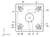
- FIG. 2 is a plan view showing a configuration on the bottom cover 15. As shown in FIG. 2, one suspension 19 is disposed at each of the four corners of the bottom cover 15. Each suspension 19 has a fixed portion 19a and a placement portion 19b. The fixing portion 19a is fixed to the bottom cover 15 by a fixing member such as a screw. A part of the second substrate 25 is placed on the placement portion 19b.
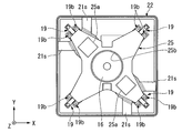
- FIG. 3 is a plan view showing a configuration on the second substrate 25.
- an electronic component having an electronic circuit such as a microprocessor 25 a is attached to the second substrate 25.
- the second substrate 25 is connected to the first substrate 14.
- An opening 25 b is formed at the center of the second substrate 25.
- a fixed portion 16a of the vibrating portion 16 is disposed in the opening 25b.
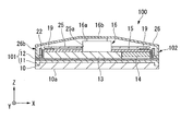
- FIG. 4 is a diagram illustrating a cross-sectional configuration of the electronic device 100.
- some components are omitted in order to make it easy to identify the components of the electronic device 100.
- the cover member 26 covers the + Z side end of the electronic device 100.
- a part 26a of the cover member 26 is detachably provided.
- the cover member 26 has a holding portion 26 b that holds the operation portion 22.
- the cover member 26 is a second housing portion 102 for accommodating an electronic circuit.
- the housing 103 of the electronic device 100 is configured by the second housing portion 102 and the first housing portion 101 including the first base portion 11 and the second base portion 12 described above.
- at least a part of the first housing portion 101 is exposed to the outside.
- at least a part of the second housing portion 102 is exposed to the outside.
- the first housing part 101 and the second housing part 102 are connected via the vibration part 16.
- the cover member 26 is connected to the movable portion 16 b of the vibrating portion 16. Therefore, the cover member 26 is provided so as to be movable in the Z direction integrally with the movable portion 16b.
- the vibration of the movable portion 16b is transmitted to the cover member 26, and the cover member 26 vibrates in the Z direction.
- the cover member 26 moves in the + Z direction as the movable portion 16b moves as shown in FIG. Accordingly, the space between the first housing portion 101 and the second housing portion 102 is widened, and the relative movement between the first housing portion 101 and the second housing portion 102 has been performed. become.
- the cover member 26 moves in the ⁇ Z direction with the movement of the movable portion 16b, and returns to the state shown in FIG. Also in this case, a relative movement has been performed between the first housing portion 101 and the second housing portion 102. In the case of this embodiment, the cover member 26 vibrates by reciprocating (vibrating) the movable portion 16b in the Z direction.
- the housing 103 having the first housing portion 101 and the second housing portion 102 for housing the electronic circuit, and the first housing portion that vibrates in a predetermined direction. Since the vibration unit 16 that relatively moves the 101 and the second housing portion 102 is provided, at least one of the first housing portion 101 and the second housing portion 102 can be directly vibrated. As a result, vibration can be efficiently transmitted to the outside.
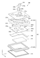
- FIG. 6 is an exploded perspective view showing the configuration of the electronic device 200 according to the second embodiment of the present invention.
- the electronic device 200 includes a display panel 210, a first base portion 211, a second base portion 212, a battery 213, a first substrate 214, a bottom cover 215, a vibration portion 216, a suspension 219, and a drive housing. 221, an operation unit 222, a second substrate 225, and a cover member 226.
- the electronic device 200 is assembled in a state where these components are stacked.
- the 1st base part 211 and the 2nd base part 212 serve as the 1st case part 201 for accommodating an electronic circuit. Further, an electronic circuit (not shown) is formed on the first substrate 214.
- an XYZ orthogonal coordinate system is used to describe the configuration of the electronic device 200.
- the stacking direction of each component of the electronic device 200 is defined as the Z direction.
- a plane orthogonal to the Z direction is defined as an XY plane, and directions orthogonal to the XY plane are defined as an X direction and a Y direction, respectively.
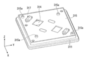
- FIG. 7 is a perspective view showing a configuration on the bottom cover 215.
- the bottom cover 215 is formed in a rectangular plate shape.
- the bottom cover 215 is disposed on the + Z side of the battery 213 and the first substrate 214, and is disposed so as to cover the battery 213 and the first substrate 214.
- a circular opening 215 a is formed at the center of the bottom cover 215. From the opening 215a, a part of the fixed part 216a of the vibration part 216 and the movable part 216b of the vibration part 216 protrude to the + Z side.
- One suspension 219 is disposed on each of the + X side and the ⁇ X side of the opening 215a.
- the driving unit 216c of the vibration unit 216 for example, a voice coil motor or the like can be used.
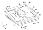
- FIG. 8 is a perspective view showing a configuration on the drive housing 221.
- the drive housing 221 has a connection part 221a, a connection part 221b, a frame part 221c, and an opening part 221d.
- the connection part 221a is a part connected to the movable part 216b.
- the connecting portion 221a is disposed at the central portion of the drive housing 221 as viewed in the Z direction, that is, at a position facing the movable portion 216b. By being connected to the movable portion 216b at the connection portion 221a, the drive housing 221 can move integrally with the movable portion 216b.
- the connecting part 221b connects the connecting part 221a and the frame part 221c.
- the connecting portion 221b is disposed on the + X side and the ⁇ X side of the connecting portion 221a, respectively.
- the connecting portion 221b is disposed at a position facing the suspension 219 when viewed in the Z direction.
- the connecting portion 221b is supported by the suspension 219.
- the frame portion 221c is supported on the peripheral edge portion of the second base portion 212.
- An opening 221d is formed in the frame portion 221c.
- the opening 221d is penetrated by a cylindrical protrusion 215b provided in the bottom cover 215.
- a smooth space is formed between the inner periphery of the opening 221d and the outer periphery of the protruding portion 215b. For this reason, friction between the inner periphery of the opening 221d and the outer periphery of the protrusion 215b is less likely to occur.
- the drive housing 221 is a second housing portion 202 for housing an electronic circuit.
- the housing 203 of the electronic device 200 is configured by the second housing portion 202 and the first housing portion 201 including the first base portion 211 and the second base portion 212 described above.
- FIG. 9 is a perspective view showing a configuration on the second substrate 225.
- the second substrate 225 is disposed on the + Z side of the drive housing 221.
- the second substrate 225 is disposed with a gap between it and the drive housing 221.
- An opening 225 a is formed at the center of the second substrate 225. In the opening 225a, a part of the fixed part 216a of the vibration part 216, a movable part 216b of the vibration part 216, and a part of the connection part 221a of the drive housing 221 are arranged.
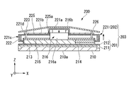
- FIG. 10 is a diagram illustrating a cross-sectional configuration of the electronic device 200.
- a part of the configuration is omitted for easy identification of the components of the electronic device 200.
- the cover member 226 covers the + Z side end of the electronic device 200.
- the cover member 226 is fixed to the bottom cover 215 together with the second substrate 225 via a fixing member 223 such as a screw.
- at least a part of the first housing portion 201 is exposed to the outside.
- at least a part of the second housing portion 202 is exposed to the outside.
- the first housing portion 201 and the second housing portion 202 are connected via the vibration unit 216.
- the drive housing 221 is connected to the movable part 216 b of the vibration part 216. Therefore, the drive housing 221 is provided so as to be movable in the Z direction integrally with the movable portion 216b.
- the vibration of the movable portion 216b is transmitted to the drive housing 221 and the drive housing 221 vibrates in the Z direction.
- the drive housing 221 moves in the + Z direction as the movable part 16b moves as shown in FIG. Therefore, the space between the first housing portion 201 and the second housing portion 202 is widened, and the relative movement between the first housing portion 201 and the second housing portion 202 has been performed. become.
- the drive housing 221 moves in the ⁇ Z direction as the movable part 216b moves, and returns to the state shown in FIG. Also in this case, a relative movement is performed between the first housing part 201 and the second housing part 202.
- the drive housing 221 vibrates in the Z direction by reciprocating (vibrating) the movable portion 216b in the Z direction.
- the housing 203 having the first housing portion 201 and the second housing portion 202 for housing the electronic circuit, and the first housing portion 201 that vibrates in a predetermined direction. Since the vibration unit 216 that relatively moves the second housing portion 202 is provided, at least one of the first housing portion 201 and the second housing portion 202 can be directly vibrated. As a result, vibration can be efficiently transmitted to the outside.
- FIG. 12 is an exploded perspective view showing the configuration of the electronic apparatus 300 according to this embodiment.
- the electronic device 300 includes a display panel 310, a base portion 311, a battery 313, a first substrate 314, a bottom cover 315, a vibration portion 316, a linear guide 317, a drive housing 321, and a fixed substrate 326. is doing.
- An electronic circuit (not shown) is formed on the first substrate 314.
- the base portion 311 is a first housing portion 301 for housing an electronic circuit.
- an XYZ orthogonal coordinate system is used to describe the configuration of the electronic device 300.
- the stacking direction of each component of the electronic device 300 is defined as the Z direction.
- a plane orthogonal to the Z direction is defined as an XY plane, and directions orthogonal to the XY plane are defined as an X direction and a Y direction, respectively.
- FIG. 13 is a perspective view showing a configuration on the bottom cover 315.
- a pair of linear guides 317 are attached on the bottom cover 315.
- the linear guide 317 is formed in a rectangular shape when viewed in the Z direction, and is arranged so that the longitudinal direction is parallel to the Y direction.
- the linear guide 317 guides the movement of the drive housing 321.
- FIG. 14 is a perspective view showing a configuration on the drive housing 321.
- the drive housing 321 is disposed on the + Z side of the bottom cover 315.
- the drive housing 321 is formed in a rectangle when viewed in the Z direction.
- the drive housing 321 includes a frame portion 321a and a beam portion 321b.
- the frame portion 321a is formed in a rectangular frame shape when viewed in the Z direction.
- the frame portion 321 a is supported on the peripheral edge portion of the base portion 311.
- the beam portion 321b is provided in a band shape within the frame of the frame portion 321a.
- the beam portion 321b is formed with a protrusion 321c and an opening 321d.
- a transmission member 316d that transmits the driving force of the vibration part 316 is joined to the beam part 321b.
- the transmission member 316d can move integrally with the beam portion 321b (drive housing 321).
- the movable part 316b of the vibration part 316 is connected to the transmission member 316d. The movement of the movable portion 316b is transmitted to the drive housing 321 via the transmission member 316d.
- the movable part 316b is arranged at a position in the Y direction with respect to the fixed part 316a. Therefore, the vibration part 316 vibrates in the Y direction along the surface of the bottom cover 315.
- a voice coil motor or the like can be used as the vibration part 316c of the vibration part 316.
- the protrusion 321c is formed in an L shape on the + Z side from the beam 321b.
- the protrusion 321 c is in contact with the linear guide 317.
- the protrusion 321c moves so as to slide in the Y direction along the linear guide 317, so that the drive housing 321 can move in parallel to the Y direction.
- the openings 321d are provided at the four corners of the drive housing 321, respectively.
- the drive housing 321 is a second housing portion 302 for housing an electronic circuit.
- the housing 303 of the electronic device 300 is configured by the second housing portion 302 and the first housing portion 301 including the base portion 311 described above.
- FIG. 15 is a perspective view showing a configuration on the fixed substrate 326.
- the fixed substrate 326 is disposed on the + Z side of the drive housing 321.
- the fixed substrate 326 is formed in a substantially rectangular shape when viewed in the Z direction.
- the fixed substrate 326 is fixed to the bottom cover 315 at four corners via fixing members (not shown).
- the fixing member passes through the opening 321d of the drive housing 321 and is fixed to the bottom cover 315.
- the outer diameter of the fixing member is smaller than the inner diameter of the opening 321d. Therefore, a gap (vibration margin) is formed between the fixing member and the beam portion 321b.
- the fixed substrate 326 has a stage 326a for fixing the fixing portion 316a of the vibrating portion 316.
- the movable portion 316b can move in the Y direction with respect to the stage 326a.
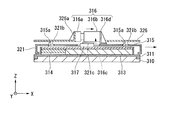
- FIG. 16 is a diagram illustrating a cross-sectional configuration of the electronic apparatus 300.
- a part of the configuration is omitted for easy identification of the components of the electronic device 300.
- at least a part of the first housing portion 301 (see FIG. 12) is exposed to the outside.
- at least a part of the second housing portion 302 (see FIG. 12) is exposed to the outside.
- the first housing portion 301 and the second housing portion 302 are connected via the vibration unit 316.
- the drive housing 321 is connected to the movable part 316b of the vibration part 316 via the transmission member 316d.
- the drive housing 321 can move in the Y direction integrally with the movable portion 316b.
- the vibration of the movable portion 316b is transmitted to the drive housing 321 and the drive housing 321 vibrates in the Z direction.
- the drive housing 321 can be vibrated so as to reciprocate on the same track by being guided by the linear guide 317.
- the drive housing 321 moves in the + Y direction as the movable part 316b moves as shown in FIG. Accordingly, the space between the first housing portion 301 and the second housing portion 302 is widened, and the relative movement between the first housing portion 301 and the second housing portion 302 has been performed. become.
- the drive housing 321 moves in the ⁇ Y direction as the movable portion 316b moves, and returns to the state shown in FIG. Also in this case, relative movement has been performed between the first housing portion 301 and the second housing portion 302. In the case of the present embodiment, the drive housing 321 vibrates in the Y direction by reciprocating (vibrating) the movable portion 316b in the Y direction.
- the housing 303 having the first housing portion 301 and the second housing portion 302 for housing the electronic circuit, and the first housing portion 301 that vibrates in a predetermined direction Since the vibration unit 316 that relatively moves the second housing portion 302 is provided, at least one of the first housing portion 301 and the second housing portion 302 can be directly vibrated. As a result, vibration can be efficiently transmitted to the outside.
- FIG. 18 is a diagram illustrating an example of the configuration.
- a bellows portion 41 is provided between the second base portion 12 that is an example of the first housing portion and a cover member 26 that is an example of the second housing portion.
- the bellows portion 41 is provided over the entire outer periphery of the electronic device. Thereby, the inside of an electronic device can be protected from foreign materials, such as dust and dust.
- the configuration in which one vibration part is arranged has been described as an example.
- the present invention is not limited to this.
- a configuration in which a plurality of vibration units are arranged may be used.
- the vibration part can be provided at a plurality of positions.
- the configuration may be such that the vibration unit 16 is arranged at each of four corners of the electronic device 100.
- the movable portion reciprocates is described as an example of the vibration by the vibration portion, but the present invention is not limited to this.
- the movable part 416b may reciprocate in a direction rotating around the fixed part 416a to generate vibration. I do not care.
- the electronic circuit is accommodated in the second casing portions 103, 203, and 303.
- all the electronic circuits are accommodated in the first casing portions 102, 201, and 301, and the second casing portion is accommodated.
- the body parts 103, 203, 303 may not contain electronic circuits.
Landscapes
- Physics & Mathematics (AREA)
- Electromagnetism (AREA)
- Engineering & Computer Science (AREA)
- Mechanical Engineering (AREA)
- Apparatuses For Generation Of Mechanical Vibrations (AREA)
- Telephone Set Structure (AREA)
Abstract
電子機器は、電子回路を収容し、第一筐体部分及び第二筐体部分を有する筐体と、所定方向に振動して前記第一筐体部分と前記第二筐体部分とを相対的に移動させる振動部とを備える。第一筐体部分及び第二筐体部分のうち少なくとも一方の少なくとも一部が外部に露出している。
Description
本発明は、電子機器に関する。
本願は、2011年7月27日に出願された特願2011-164310号に基づき優先権を主張し、その内容をここに援用する。
本願は、2011年7月27日に出願された特願2011-164310号に基づき優先権を主張し、その内容をここに援用する。
携帯電話や携帯情報端末などの電子機器として、例えば特許文献1に記載の技術が知られている。特許文献1に示すような電子機器においては、ユーザに振動を検知させる構成が用いられる場合がある。このような振動を発生させる振動発生装置として、例えば振動モーターが知られている。振動モーターとしては、例えば円筒型の回転子の先端に錘をつけ、回転子の回転により振動が発生する構成が知られている。
しかしながら、従来の振動発生装置においては、モーターを介して筐体に振動を伝達させる構成であるため、振動が外部に十分に伝達されない場合も考えられる。
本発明の態様は、振動を効率的に外部に伝達することが可能な電子機器を提供することを目的とする。
本発明の態様に従えば、電子回路を収容し、第一筐体部分及び第二筐体部分を有する筐体と、所定方向に振動して前記第一筐体部分と前記第二筐体部分とを相対的に移動させる振動部とを備え、前記第一筐体部分及び前記第二筐体部分のうち少なくとも一方の少なくとも一部が外部に露出している電子機器が提供される。
本発明の態様によれば、振動を効率的に外部に伝達することが可能な電子機器を提供することができる。
以下、図面を参照して、本発明の実施の形態を説明する。
[第一実施形態]
図1は、本発明の第一実施形態に係る電子機器100の構成を示す分解斜視図である。図1に示すように、電子機器100は、表示パネル10、第一ベース部11、第二ベース部12、バッテリー13、第一基板14、ボトムカバー15、振動部16、サスペンション19、操作部22、第二基板25及びカバー部材26を有している。電子機器100は、これらの各構成要素が積層された状態で組み立てられている。
[第一実施形態]
図1は、本発明の第一実施形態に係る電子機器100の構成を示す分解斜視図である。図1に示すように、電子機器100は、表示パネル10、第一ベース部11、第二ベース部12、バッテリー13、第一基板14、ボトムカバー15、振動部16、サスペンション19、操作部22、第二基板25及びカバー部材26を有している。電子機器100は、これらの各構成要素が積層された状態で組み立てられている。
以下、本実施形態において、電子機器100の構成を説明するに当たり、XYZ直交座標系を用いる。XYZ直交座標系において、電子機器100の各構成要素の積層方向をZ方向とする。また、Z方向に直交する平面をXY平面とし、XY平面において直交する方向をそれぞれX方向及びY方向とする。
表示パネル10は、Z方向視で矩形に形成されている。表示パネル10は、-Z側の面が表示面10aとなっている。表示面10aには、静止画や動画などの画像が表示される。表示パネル10としては、例えば液晶表示パネルや、有機ELパネルなどが用いられる。代替的に、表示パネル10の表示面10a上に、不図示のタッチパネル機構を設けることができる。
第一ベース部11は、表示パネル10を保持する。第一ベース部11は、Z方向視で矩形の枠状に形成されている。第一ベース部11は、表示パネル10の側部及び表示面10aの周縁部を囲うように形成されている。第二ベース部12は、第一ベース部11の+Z側に配置されている。第二ベース部12の一部は、第一ベース部11に支持されている。第一ベース部11及び第二ベース部12は、電子回路を収容するための第一筐体部分101となっている。
バッテリー13は、外形が矩形の板状に形成されている。バッテリー13は、電子機器100の各部に電力を供給する。バッテリー13は、不図示の配線を介して電子機器100の各部に接続されている。バッテリー13の+Z側の面13aは、平坦に形成されている。
第一基板14は、バッテリー13が配置されるスペースを空けるように、外形がL字状に形成されている。第一基板14は、第二ベース部12に支持されている。第一基板14には、制御回路14aが形成されている。電子機器100は、制御回路14aにより、電子機器100の各部が電気的に制御される構成となっている。
ボトムカバー15は、矩形板状に形成されている。ボトムカバー15は、バッテリー13及び第一基板14の+Z側に配置され、バッテリー13及び第一基板14を覆うように配置されている。ボトムカバー15の中央部には、円形の開口部15aが形成されている。開口部15aには、バッテリー13の+Z側の面13aが一部露出している。
振動部16は、固定部16a、可動部16b及び駆動部16cを有する。固定部16aは、円筒状に形成されており、可動部16b及び駆動部16cを収容する。固定部16aは、ボトムカバー15の開口部15a内に配置されている。
可動部16bは、Z方向に移動可能に設けられている。駆動部16cは、可動部16bに接続されており、可動部16bをZ方向に移動させる。駆動部16cとしては、例えばボイスコイルモーターなどが用いられている。駆動部16cの駆動動作は、上記の第一基板14に設けられた制御回路14aによって制御される。振動部16は、駆動部16cが可動部16bをZ方向に往復移動させることにより、可動部16bがZ方向に振動する構成である。
サスペンション19は、カバー部材26を支持する部分である。図2は、ボトムカバー15上の構成を示す平面図である。図2に示すように、サスペンション19は、ボトムカバー15の4つの角部にそれぞれ1つずつ配置されている。各サスペンション19は、固定部19a及び載置部19bを有している。固定部19aは、ネジなどの固定部材によってボトムカバー15に固定されている。載置部19bには、第二基板25の一部分がそれぞれ載置される。
図3は、第二基板25上の構成を示す平面図である。図3に示すように、第二基板25には、例えばマイクロプロセッサ25aなど電子回路を有する電子部品が取り付けられている。第二基板25は、第一基板14に接続されている。第二基板25の中央部には、開口部25bが形成されている。開口部25bには、振動部16の固定部16aが配置されている。
図4は、電子機器100の断面構成を示す図である。図4においては、電子機器100の構成要素を判別しやすくするため、一部の構成を省略して示している。
図1及び図4に示すように、カバー部材26は、電子機器100の+Z側の端部を覆っている。図1に示すように、カバー部材26の一部分26aは、着脱可能に設けられている。図4に示すように、カバー部材26は、操作部22を保持する保持部26bを有している。
図1及び図4に示すように、カバー部材26は、電子機器100の+Z側の端部を覆っている。図1に示すように、カバー部材26の一部分26aは、着脱可能に設けられている。図4に示すように、カバー部材26は、操作部22を保持する保持部26bを有している。
カバー部材26は、電子回路を収容するための第二筐体部分102となっている。また、第二筐体部分102と、上記の第一ベース部11及び第二ベース部12からなる第一筐体部分101とにより、電子機器100の筐体103が構成されている。本実施形態において、第一筐体部分101の少なくとも一部が外部に露出している。また、本実施形態において、第二筐体部分102の少なくとも一部が外部に露出している。また、本実施形態において、第一筐体部分101と第二筐体部分102とは、振動部16を介して接続されている。
図4に示すように、カバー部材26は、振動部16の可動部16bに接続されている。したがって、カバー部材26は、可動部16bと一体的にZ方向に移動可能に設けられている。可動部16bがZ方向に振動することにより、可動部16bの振動がカバー部材26に伝達され、カバー部材26がZ方向に振動する。
例えば、可動部16bが図4に示す状態から+Z方向に移動する場合には、図5に示すように、カバー部材26は可動部16bの移動に伴って+Z方向へ移動する。したがって、第一筐体部分101と第二筐体部分102との間が広がることになり、第一筐体部分101と第二筐体部分102との間で相対的な移動が行われたことになる。
また、可動部16bが図5に示す状態から-Z方向に移動する場合には、カバー部材26は可動部16bの移動に伴って-Z方向へ移動し、図4に示す状態に戻る。この場合にも、第一筐体部分101と第二筐体部分102との間で相対的な移動が行われたことになる。本実施形態の場合、可動部16bをZ方向に往復移動(振動)させることにより、カバー部材26が振動する。
以上のように、本実施形態によれば、電子回路を収容するための第一筐体部分101及び第二筐体部分102を有する筐体103と、所定方向に振動して第一筐体部分101と第二筐体部分102とを相対的に移動させる振動部16とを備えるため、第一筐体部分101及び第二筐体部分102のうち少なくとも一方を直接振動させることができる。これにより、振動を効率的に外部に伝達することが可能となる。
[第二実施形態]
次に、本発明の第二実施形態を説明する。
図6は、本発明の第二実施形態に係る電子機器200の構成を示す分解斜視図である。図6に示すように、電子機器200は、表示パネル210、第一ベース部211、第二ベース部212、バッテリー213、第一基板214、ボトムカバー215、振動部216、サスペンション219、駆動筐体221、操作部222、第二基板225及びカバー部材226を有している。
次に、本発明の第二実施形態を説明する。
図6は、本発明の第二実施形態に係る電子機器200の構成を示す分解斜視図である。図6に示すように、電子機器200は、表示パネル210、第一ベース部211、第二ベース部212、バッテリー213、第一基板214、ボトムカバー215、振動部216、サスペンション219、駆動筐体221、操作部222、第二基板225及びカバー部材226を有している。
電子機器200は、これらの各構成要素が積層された状態で組み立てられている。第一ベース部211及び第二ベース部212は、電子回路を収容するための第一筐体部分201となっている。また、第一基板214には、電子回路(不図示)が形成されている。
以下、本実施形態において、電子機器200の構成を説明するに当たり、XYZ直交座標系を用いる。XYZ直交座標系において、電子機器200の各構成要素の積層方向をZ方向とする。また、Z方向に直交する平面をXY平面とし、XY平面において直交する方向をそれぞれX方向及びY方向とする。
図7は、ボトムカバー215上の構成を示す斜視図である。
図6及び図7に示すように、ボトムカバー215は、矩形板状に形成されている。ボトムカバー215は、バッテリー213及び第一基板214の+Z側に配置され、バッテリー213及び第一基板214を覆うように配置されている。ボトムカバー215の中央部には、円形の開口部215aが形成されている。開口部215aからは、振動部216の固定部216aの一部と、振動部216の可動部216bとが+Z側に突出している。開口部215aの+X側及び-X側には、それぞれサスペンション219が1つずつ配置されている。振動部216の駆動部216cとしては、例えばボイスコイルモーターなどを用いることができる。
図6及び図7に示すように、ボトムカバー215は、矩形板状に形成されている。ボトムカバー215は、バッテリー213及び第一基板214の+Z側に配置され、バッテリー213及び第一基板214を覆うように配置されている。ボトムカバー215の中央部には、円形の開口部215aが形成されている。開口部215aからは、振動部216の固定部216aの一部と、振動部216の可動部216bとが+Z側に突出している。開口部215aの+X側及び-X側には、それぞれサスペンション219が1つずつ配置されている。振動部216の駆動部216cとしては、例えばボイスコイルモーターなどを用いることができる。
図8は、駆動筐体221上の構成を示す斜視図である。
図8に示すように、駆動筐体221は、接続部221a、連結部221b、フレーム部221c及び開口部221dを有している。接続部221aは、可動部216bに接続される部分である。接続部221aは、Z方向視で駆動筐体221の中央部、すなわち、可動部216bに対向する位置に配置されている。接続部221aにおいて可動部216bに接続されることにより、駆動筐体221は可動部216bと一体的に移動可能となっている。
図8に示すように、駆動筐体221は、接続部221a、連結部221b、フレーム部221c及び開口部221dを有している。接続部221aは、可動部216bに接続される部分である。接続部221aは、Z方向視で駆動筐体221の中央部、すなわち、可動部216bに対向する位置に配置されている。接続部221aにおいて可動部216bに接続されることにより、駆動筐体221は可動部216bと一体的に移動可能となっている。
連結部221bは、接続部221aとフレーム部221cとを連結する。連結部221bは、接続部221aの+X側及び-X側にそれぞれ配置されている。連結部221bは、Z方向視で、サスペンション219に対向する位置に配置されている。連結部221bは、サスペンション219に支持されている。
フレーム部221cは、第二ベース部212の周縁部に支持されている。フレーム部221cには、開口部221dが形成されている。開口部221dは、ボトムカバー215に設けられた円筒状の突出部215bによって貫通されている。開口部221dの内周と突出部215bの外周との間は、滑らかに形成されている。このため、開口部221dの内周と突出部215bの外周の間での摩擦が生じにくくなっている。
駆動筐体221は、電子回路を収容するための第二筐体部分202となっている。また、第二筐体部分202と、上記の第一ベース部211及び第二ベース部212からなる第一筐体部分201とにより、電子機器200の筐体203が構成されている。
図9は、第二基板225上の構成を示す斜視図である。
図9に示すように、第二基板225は、駆動筐体221の+Z側に配置されている。第二基板225は、駆動筐体221との間に隙間を空けて配置されている。第二基板225の中央部には、開口部225aが形成されている。開口部225a内には、振動部216の固定部216aの一部と、振動部216の可動部216bと、駆動筐体221の接続部221aの一部とが配置されている。
図9に示すように、第二基板225は、駆動筐体221の+Z側に配置されている。第二基板225は、駆動筐体221との間に隙間を空けて配置されている。第二基板225の中央部には、開口部225aが形成されている。開口部225a内には、振動部216の固定部216aの一部と、振動部216の可動部216bと、駆動筐体221の接続部221aの一部とが配置されている。
図10は、電子機器200の断面構成を示す図である。図10においては、電子機器200の構成要素を判別しやすくするため、一部の構成を省略して示している。
図10に示すように、カバー部材226は、電子機器200の+Z側の端部を覆っている。カバー部材226は、ネジなどの固定部材223を介して、第二基板225と共にボトムカバー215に固定されている。本実施形態において、第一筐体部分201の少なくとも一部が外部に露出している。また、本実施形態において、第二筐体部分202の少なくとも一部が外部に露出している。また、本実施形態において、第一筐体部分201と第二筐体部分202とは、振動部216を介して接続されている。
図10に示すように、カバー部材226は、電子機器200の+Z側の端部を覆っている。カバー部材226は、ネジなどの固定部材223を介して、第二基板225と共にボトムカバー215に固定されている。本実施形態において、第一筐体部分201の少なくとも一部が外部に露出している。また、本実施形態において、第二筐体部分202の少なくとも一部が外部に露出している。また、本実施形態において、第一筐体部分201と第二筐体部分202とは、振動部216を介して接続されている。
図10に示すように、駆動筐体221は、振動部216の可動部216bに接続されている。したがって、駆動筐体221は、可動部216bと一体的にZ方向に移動可能に設けられている。可動部216bがZ方向に振動することにより、可動部216bの振動が駆動筐体221に伝達され、駆動筐体221がZ方向に振動する。
例えば、可動部216bが図10に示す状態から+Z方向に移動する場合には、図11に示すように、駆動筐体221は可動部16bの移動に伴って+Z方向へ移動する。したがって、第一筐体部分201と第二筐体部分202との間が広がることになり、第一筐体部分201と第二筐体部分202との間で相対的な移動が行われたことになる。
また、可動部216bが図11に示す状態から-Z方向に移動する場合には、駆動筐体221は可動部216bの移動に伴って-Z方向へ移動し、図10に示す状態に戻る。この場合にも、第一筐体部分201と第二筐体部分202との間で相対的な移動が行われたことになる。本実施形態の場合、可動部216bをZ方向に往復移動(振動)させることにより、駆動筐体221がZ方向に振動する。
以上により、本実施形態によれば、電子回路を収容するための第一筐体部分201及び第二筐体部分202を有する筐体203と、所定方向に振動して第一筐体部分201と第二筐体部分202とを相対的に移動させる振動部216とを備えるため、第一筐体部分201及び第二筐体部分202のうち少なくとも一方を直接振動させることができる。これにより、振動を効率的に外部に伝達することが可能となる。
[第三実施形態]
次に、本発明の第三実施形態を説明する。図12は、本実施形態に係る電子機器300の構成を示す分解斜視図である。図12に示すように、電子機器300は、表示パネル310、ベース部311、バッテリー313、第一基板314、ボトムカバー315、振動部316、リニアガイド317、駆動筐体321及び固定基板326を有している。第一基板314には、電子回路(不図示)が形成されている。ベース部311は、電子回路を収容するための第一筐体部分301となっている。
次に、本発明の第三実施形態を説明する。図12は、本実施形態に係る電子機器300の構成を示す分解斜視図である。図12に示すように、電子機器300は、表示パネル310、ベース部311、バッテリー313、第一基板314、ボトムカバー315、振動部316、リニアガイド317、駆動筐体321及び固定基板326を有している。第一基板314には、電子回路(不図示)が形成されている。ベース部311は、電子回路を収容するための第一筐体部分301となっている。
以下、本実施形態において、電子機器300の構成を説明するに当たり、XYZ直交座標系を用いる。XYZ直交座標系において、電子機器300の各構成要素の積層方向をZ方向とする。また、Z方向に直交する平面をXY平面とし、XY平面において直交する方向をそれぞれX方向及びY方向とする。
本実施形態では、振動部316の動作によって駆動筐体321がY方向(積層方向に直交する方向)に振動する態様を例に挙げて説明する。
図13は、ボトムカバー315上の構成を示す斜視図である。
図13に示すように、ボトムカバー315上には、一対のリニアガイド317が取り付けられている。リニアガイド317は、Z方向視で矩形に形成されており、長手方向がY方向に平行になるように配置されている。リニアガイド317は、駆動筐体321の移動を案内する。
図13は、ボトムカバー315上の構成を示す斜視図である。
図13に示すように、ボトムカバー315上には、一対のリニアガイド317が取り付けられている。リニアガイド317は、Z方向視で矩形に形成されており、長手方向がY方向に平行になるように配置されている。リニアガイド317は、駆動筐体321の移動を案内する。
図14は、駆動筐体321上の構成を示す斜視図である。
図14に示すように、駆動筐体321は、ボトムカバー315の+Z側に配置されている。駆動筐体321は、Z方向視で矩形に形成されている。駆動筐体321は、フレーム部321a及び梁部321bを有している。
図14に示すように、駆動筐体321は、ボトムカバー315の+Z側に配置されている。駆動筐体321は、Z方向視で矩形に形成されている。駆動筐体321は、フレーム部321a及び梁部321bを有している。
フレーム部321aは、Z方向視で矩形の枠状に形成されている。フレーム部321aは、ベース部311の周縁部に支持されている。梁部321bは、フレーム部321aの枠内に帯状に設けられている。梁部321bには、突起部321c及び開口部321dが形成されている。
梁部321bには、振動部316の駆動力を伝達する伝達部材316dが接合されている。伝達部材316dは、梁部321b(駆動筐体321)と一体的に移動可能である。伝達部材316dには、振動部316の可動部316bが接続されている。可動部316bの移動は、伝達部材316dを介して駆動筐体321に伝達される。
振動部316は、固定部316aに対して可動部316bがY方向上の位置に配置されている。したがって、振動部316は、ボトムカバー315の表面に沿ってY方向に振動することになる。振動部316の振動部316cとしては、例えばボイスコイルモーターなどを用いることができる。
突起部321cは、梁部321bから+Z側にL字状に形成されている。突起部321cは、リニアガイド317に当接されている。突起部321cがリニアガイド317に沿ってY方向に滑るように移動することで、駆動筐体321はY方向に平行に移動可能となっている。開口部321dは、駆動筐体321の4つの角部にそれぞれ設けられている。
駆動筐体321は、電子回路を収容するための第二筐体部分302となっている。また、第二筐体部分302と、上記のベース部311からなる第一筐体部分301とにより、電子機器300の筐体303が構成されている。
図15は、固定基板326上の構成を示す斜視図である。
図15に示すように、固定基板326は、駆動筐体321の+Z側に配置されている。固定基板326は、Z方向視でほぼ矩形に形成されている。固定基板326は、4つの角部において不図示の固定部材を介してボトムカバー315に固定されている。
図15に示すように、固定基板326は、駆動筐体321の+Z側に配置されている。固定基板326は、Z方向視でほぼ矩形に形成されている。固定基板326は、4つの角部において不図示の固定部材を介してボトムカバー315に固定されている。
固定部材は、駆動筐体321の開口部321dを貫通してボトムカバー315に固定される。この場合、固定部材の外径は、開口部321dの内径よりも小さく形成されている。したがって、固定部材と梁部321bとの間に隙間(振動のマージン)が形成された状態になっている。
固定基板326は、振動部316の固定部316aを固定させるステージ326aを有している。固定部316aがステージ326aに固定されることで、可動部316bはステージ326aに対してY方向に移動可能となる。
図16は、電子機器300の断面構成を示す図である。図16においては、電子機器300の構成要素を判別しやすくするため、一部の構成を省略して示している。本実施形態において、第一筐体部分301(図12参照)の少なくとも一部が外部に露出している。また、本実施形態において、第二筐体部分302(図12参照)の少なくとも一部が外部に露出している。また、本実施形態において、第一筐体部分301と第二筐体部分302とは、振動部316を介して接続されている。
図16に示すように、駆動筐体321は、伝達部材316dを介して振動部316の可動部316bに接続されている。したがって、駆動筐体321は、可動部316bと一体的にY方向に移動可能である。可動部316bがY方向に振動することにより、可動部316bの振動が駆動筐体321に伝達され、駆動筐体321がZ方向に振動する。また、駆動筐体321は、リニアガイド317に案内されることで、等しい軌道を往復するように振動することができる。
図16に示すように、駆動筐体321は、伝達部材316dを介して振動部316の可動部316bに接続されている。したがって、駆動筐体321は、可動部316bと一体的にY方向に移動可能である。可動部316bがY方向に振動することにより、可動部316bの振動が駆動筐体321に伝達され、駆動筐体321がZ方向に振動する。また、駆動筐体321は、リニアガイド317に案内されることで、等しい軌道を往復するように振動することができる。
例えば、可動部316bが図16に示す状態から+Y方向に移動する場合には、図17に示すように、駆動筐体321は可動部316bの移動に伴って+Y方向へ移動する。したがって、第一筐体部分301と第二筐体部分302との間が広がることになり、第一筐体部分301と第二筐体部分302との間で相対的な移動が行われたことになる。
また、可動部316bが図17に示す状態から-Y方向に移動する場合には、駆動筐体321は可動部316bの移動に伴って-Y方向へ移動し、図16に示す状態に戻る。この場合にも、第一筐体部分301と第二筐体部分302との間で相対的な移動が行われたことになる。本実施形態の場合、可動部316bをY方向に往復移動(振動)させることにより、駆動筐体321がY方向に振動する。
以上により、本実施形態によれば、電子回路を収容するための第一筐体部分301及び第二筐体部分302を有する筐体303と、所定方向に振動して第一筐体部分301と第二筐体部分302とを相対的に移動させる振動部316とを備えるため、第一筐体部分301及び第二筐体部分302のうち少なくとも一方を直接振動させることができる。これにより、振動を効率的に外部に伝達することが可能となる。
本発明の技術範囲は上記実施形態に限定されるものではなく、本発明の趣旨を逸脱しない範囲で適宜変更を加えることができる。
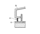
例えば、上記各実施形態において、第一筐体部分と第二筐体部分との間を密閉する構成としても構わない。図18は、構成の一例を示す図である。図18に示すように、第一筐体部分の一例である第二ベース部12と、第二筐体部分の一例であるカバー部材26との間に、蛇腹部41が設けられている。蛇腹部41は、電子機器の外周の全面に亘って設けられている。これにより、電子機器の内部を塵や埃などの異物から保護することができる。
例えば、上記各実施形態において、第一筐体部分と第二筐体部分との間を密閉する構成としても構わない。図18は、構成の一例を示す図である。図18に示すように、第一筐体部分の一例である第二ベース部12と、第二筐体部分の一例であるカバー部材26との間に、蛇腹部41が設けられている。蛇腹部41は、電子機器の外周の全面に亘って設けられている。これにより、電子機器の内部を塵や埃などの異物から保護することができる。
また、上記各実施形態では、振動部を1個配置させる構成を例に挙げて説明したが、これに限られることは無い。例えば振動部を複数配置させる構成であっても構わない。この場合、振動部を複数位置に設けることができる。図19に示すように、例えば振動部16を電子機器100の4つの角部に1つずつ配置させた構成であっても構わない。
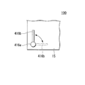
また、上記各実施形態では、振動部による振動の態様として、可動部が往復移動する場合を例に挙げて説明したが、これに限られることは無い。例えば、図20に示すように、固定部416a及び可動部416bを有する振動部416において、可動部416bが固定部416aを中心に回動する方向に往復移動することで振動を発生させる構成としても構わない。
また、上記各実施形態では、第二筐体部分103、203、303に電子回路を収容しているが、第一筐体部分102、201、301にすべての電子回路を収容して第二筐体部分103、203、303には電子回路を収容しないようにしても構わない。
100、200、300…電子機器 101、201、301…第一筐体部分 102、201、301…第二筐体部分 103、203、303…筐体 16、216、316…振動部
Claims (15)
- 電子回路を収容し、第一筐体部分及び第二筐体部分を有する筐体と、
所定方向に振動して前記第一筐体部分と前記第二筐体部分とを相対的に移動させる振動部とを備え、
前記第一筐体部分及び前記第二筐体部分のうち少なくとも一方の少なくとも一部が外部に露出している、電子機器。 - 前記第一筐体部分と前記第二筐体部分とは、前記振動部を介して接続されている
請求項1に記載の電子機器。 - 前記第一筐体部分に対して前記第二筐体部分の全体が相対的に移動する
請求項1又は請求項2に記載の電子機器。 - 前記振動部は、前記第一筐体部分と前記第二筐体部分との間に配置されている
請求項1から請求項3のうちいずれか一項に記載の電子機器。 - 前記振動部は、前記第一筐体部分に固定されている
請求項1から請求項4のうちいずれか一項に記載の電子機器。 - 前記振動部は、固定部と、可動部と、前記可動部を駆動する駆動部とを有し、
前記固定部は、前記第一筐体部分に固定されている
請求項1から請求項5のうちいずれか一項に記載の電子機器。 - 前記可動部は、前記第二筐体部分に接続されている
請求項6に記載の電子機器。 - 前記駆動部がボイスコイルモーターである
請求項6又は請求項7に記載の電子機器。 - 前記第一筐体部分には、前記電子部品に電力を供給するバッテリーが設けられている
請求項1から請求項8のうちいずれか一項に記載の電子機器。 - 前記第一筐体部分には、表示パネルが設けられている
請求項1から請求項9のうちいずれか一項に記載の電子機器。 - 前記振動部は、複数設けられている
請求項1から請求項10のうちいずれか一項に記載の電子機器。 - 前記第一筐体部分と前記第二筐体部分との間を密閉するシール部
を更に備える請求項1から請求項11のうちいずれか一項に記載の電子機器。 - 前記第一筐体部分及び前記第二筐体部分は、一方向に積層されている
請求項1から請求項12のうちいずれか一項に記載の電子機器。 - 前記所定方向は、前記一方向に平行な方向である
請求項13に記載の電子機器。 - 前記所定方向は、前記一方向に交差する方向である
請求項13に記載の電子機器。
Applications Claiming Priority (2)
| Application Number | Priority Date | Filing Date | Title |
|---|---|---|---|
| JP2011164310 | 2011-07-27 | ||
| JP2011-164310 | 2011-07-27 |
Publications (1)
| Publication Number | Publication Date |
|---|---|
| WO2013015324A1 true WO2013015324A1 (ja) | 2013-01-31 |
Family
ID=47601163
Family Applications (1)
| Application Number | Title | Priority Date | Filing Date |
|---|---|---|---|
| PCT/JP2012/068856 Ceased WO2013015324A1 (ja) | 2011-07-27 | 2012-07-25 | 電子機器 |
Country Status (2)
| Country | Link |
|---|---|
| JP (1) | JPWO2013015324A1 (ja) |
| WO (1) | WO2013015324A1 (ja) |
Citations (4)
| Publication number | Priority date | Publication date | Assignee | Title |
|---|---|---|---|---|
| JPH0225077U (ja) * | 1988-08-04 | 1990-02-19 | ||
| JP2008236637A (ja) * | 2007-03-23 | 2008-10-02 | Kenwood Corp | 加振型音響発生器および加振型音響発生器付きヘルメット |
| JP2009125403A (ja) * | 2007-11-27 | 2009-06-11 | Gijinki Kogei:Kk | 振動移動装置 |
| JP2009240749A (ja) * | 2008-03-31 | 2009-10-22 | Takuma Yoshikawa | 超音波による電磁波励起強化法およびその適用機器 |
-
2012
- 2012-07-25 JP JP2013525740A patent/JPWO2013015324A1/ja active Pending
- 2012-07-25 WO PCT/JP2012/068856 patent/WO2013015324A1/ja not_active Ceased
Patent Citations (4)
| Publication number | Priority date | Publication date | Assignee | Title |
|---|---|---|---|---|
| JPH0225077U (ja) * | 1988-08-04 | 1990-02-19 | ||
| JP2008236637A (ja) * | 2007-03-23 | 2008-10-02 | Kenwood Corp | 加振型音響発生器および加振型音響発生器付きヘルメット |
| JP2009125403A (ja) * | 2007-11-27 | 2009-06-11 | Gijinki Kogei:Kk | 振動移動装置 |
| JP2009240749A (ja) * | 2008-03-31 | 2009-10-22 | Takuma Yoshikawa | 超音波による電磁波励起強化法およびその適用機器 |
Also Published As
| Publication number | Publication date |
|---|---|
| JPWO2013015324A1 (ja) | 2015-02-23 |
Similar Documents
| Publication | Publication Date | Title |
|---|---|---|
| CN109980885B (zh) | 振动驱动器及便携设备 | |
| US10610892B2 (en) | Vibration actuator and portable device | |
| JP6010080B2 (ja) | リニア振動モータ | |
| JP2007026344A (ja) | 座標入力装置 | |
| US20200133397A1 (en) | Touchpad module | |
| JP2009268236A (ja) | リニア駆動型超音波モータ | |
| CN107710572B (zh) | 线性振动马达 | |
| US10447131B2 (en) | Linear vibration motor | |
| JP6591248B2 (ja) | リニア振動モータ | |
| WO2017051843A1 (ja) | リニア振動モータ | |
| CN105459104A (zh) | 机器人 | |
| WO2016167297A1 (ja) | リニア振動モータ | |
| CN116054522A (zh) | 致动器 | |
| JP5954405B2 (ja) | 電子機器 | |
| CN112018992A (zh) | 致动器及触觉设备 | |
| US12131627B2 (en) | Tactile feedback system | |
| WO2016084807A1 (ja) | リニア振動モータ | |
| TWI466622B (zh) | 手持電子裝置 | |
| CN113396532A (zh) | 振子支承构造、振动马达以及电子设备 | |
| JPWO2013015324A1 (ja) | 電子機器 | |
| JP2010051163A (ja) | リニアモータ | |
| JP4741400B2 (ja) | 座標入力装置 | |
| US12413114B2 (en) | Vibration motor with housing having first and second notches for lead wire and flexible printed circuit board | |
| JP5717822B2 (ja) | 振動波モータ | |
| WO2023047697A1 (ja) | リニア振動モータ |
Legal Events
| Date | Code | Title | Description |
|---|---|---|---|
| 121 | Ep: the epo has been informed by wipo that ep was designated in this application |
Ref document number: 12817422 Country of ref document: EP Kind code of ref document: A1 |
|
| ENP | Entry into the national phase |
Ref document number: 2013525740 Country of ref document: JP Kind code of ref document: A |
|
| NENP | Non-entry into the national phase |
Ref country code: DE |
|
| 122 | Ep: pct application non-entry in european phase |
Ref document number: 12817422 Country of ref document: EP Kind code of ref document: A1 |