WO2013015189A1 - 通信方法、通信システム、無線端末、および基地局 - Google Patents
通信方法、通信システム、無線端末、および基地局 Download PDFInfo
- Publication number
- WO2013015189A1 WO2013015189A1 PCT/JP2012/068317 JP2012068317W WO2013015189A1 WO 2013015189 A1 WO2013015189 A1 WO 2013015189A1 JP 2012068317 W JP2012068317 W JP 2012068317W WO 2013015189 A1 WO2013015189 A1 WO 2013015189A1
- Authority
- WO
- WIPO (PCT)
- Prior art keywords
- wireless terminal
- connection
- communication
- call
- wireless
- Prior art date
- Legal status (The legal status is an assumption and is not a legal conclusion. Google has not performed a legal analysis and makes no representation as to the accuracy of the status listed.)
- Ceased
Links
Images







Classifications
-
- H—ELECTRICITY
- H04—ELECTRIC COMMUNICATION TECHNIQUE
- H04W—WIRELESS COMMUNICATION NETWORKS
- H04W76/00—Connection management
- H04W76/10—Connection setup
-
- H—ELECTRICITY
- H04—ELECTRIC COMMUNICATION TECHNIQUE
- H04M—TELEPHONIC COMMUNICATION
- H04M2250/00—Details of telephonic subscriber devices
- H04M2250/62—Details of telephonic subscriber devices user interface aspects of conference calls
Definitions
- the present invention relates to a communication method, a communication system, a wireless terminal, and a base station capable of multi-party communication.
- LTE Long Term Evolution: long-term evolution (third generation)
- LTE-A Long-term evolution
- LTE-A is required to realize higher speed and larger capacity communication than LTE. Therefore, LTE-A is supposed to support a wider frequency range than LTE. According to the studies up to now, the maximum transmission bandwidth of LTE is 20 MHz, whereas the maximum transmission bandwidth of LTE-A is extended to 100 MHz.
- CA carrier aggregation
- PoC Push-to-Talk over Cellular
- a wireless terminal to which the server has been given the right to speak transmits voice data to the server, and the server distributes the transmitted voice data to other wireless terminals connected in real time.
- group call multi-party communication
- each of the plurality of wireless terminals communicates with a server connected via a wireless line.
- the server transmits voice data and the like to other connected wireless terminals.
- each wireless terminal such as a teleconferencing system can transmit audio data at an arbitrary timing
- a system in which only a wireless terminal to which a speaking right such as PoC is given can transmit audio data.
- a server connected to each wireless terminal is installed, and the server synthesizes voice data transmitted from each wireless terminal via a wireless line. It is assumed that the synthesized voice data is distributed to each wireless terminal.
- an object of the present invention is to provide a communication method, a communication system, and a communication system that realize multi-party communication while eliminating a server that synthesizes voice data. It is to provide a wireless terminal and a base station.
- a communication method for performing multi-party communication between a plurality of wireless terminals is provided.
- the first wireless terminal requests connection to the second and third wireless terminals, and the base station corresponding to the first wireless terminal transmits the first wireless terminal and the second wireless terminal.
- the first wireless terminal instructs the second wireless terminal to connect to the third wireless terminal, and the second wireless terminal responds to the instruction from the first wireless terminal.
- a communication system that performs multi-party communication.
- the communication system includes a plurality of wireless terminals and a plurality of base stations that provide a predetermined cell area. Means for requesting connection to a plurality of wireless terminals, and means for instructing one of the plurality of wireless terminals that requested connection to connect to the remaining wireless terminals And means for requesting a connection to the indicated wireless terminal in response to an instruction to connect to any of the wireless terminals.
- the base station includes means for establishing a plurality of connections having different frequencies from each other in response to a connection request from a wireless terminal present in a cell area provided by the base station to the plurality of wireless terminals.
- a wireless terminal capable of multi-party communication.
- the wireless terminal includes means for requesting connection to a plurality of other wireless terminals.
- a base station that provides a cell area in which the wireless terminal exists establishes a plurality of connections having different frequencies.
- the wireless terminal further provides means for instructing connection to the remaining wireless terminals to one of the plurality of wireless terminals that have requested connection, and an instruction to connect to any of the wireless terminals.
- means for requesting a connection to the indicated wireless terminal in response to a connection to the indicated wireless terminal.
- a base station capable of multi-party communication.
- the base station includes means for establishing a plurality of connections having different frequencies from each other in response to a connection request from a wireless terminal existing in the cell area to be provided to the plurality of wireless terminals.
- FIG. 6 is a schematic diagram showing a dedicated line between UEs using the component carrier shown in FIG. 5.
- FIG. 1 is a schematic diagram showing an overall configuration of a communication system 1 according to an embodiment of the present invention. As a typical example, it is assumed that the communication system 1 supports a communication method according to the LTE method or the LTE-A method.
- a communication system 1 includes mobile terminals (hereinafter also referred to as “UE (User Equipment)”) 100-1 to 100-3 and a plurality of base stations (Broadcast Station). 200-1 to 200-3, a mobile management device (Mobility Management Entity: hereinafter also referred to as “MME”) 300, and a core network 400.
- UE User Equipment
- MME Mobile Management Entity
- Each of UEs 100-1 to 100-3 (hereinafter also collectively referred to as “UE100”) is typically a mobile phone, a PDA (Personal Digital Assistant), a data communication terminal, and the like, via any BS. Exchange data with the other party.
- UE100 is typically a mobile phone, a PDA (Personal Digital Assistant), a data communication terminal, and the like, via any BS. Exchange data with the other party.
- Each of the BSs 200-1 to 200-3 (hereinafter collectively referred to as “BS200”) can transmit and receive a plurality of independent radio signals having different frequencies. That is, the BS 200 supports carrier aggregation, and exchanges data with a single UE 100 using a plurality of component carriers, as will be described later.
- carrier aggregation according to the LTE scheme or LTE-A scheme, it is generally assumed that a series of data is transmitted and received using a plurality of component carriers.
- one or a plurality of component carriers for transmitting and receiving data independently from each other are allocated to a single UE 100.
- communication can be performed in parallel between a single UE 100 and a plurality of other UEs 100.
- BSs 200-1 to 200-3 cover cell areas C201 to C203, respectively, and a plurality of component carriers are prepared in each of cell areas C201 to C203. That is, each of BSs 200-1 to 200-3 provides a predetermined cell area. And these component carriers are suitably allocated with respect to UE100.
- component carriers are assigned to the respective frequency bands.
- a component carrier in the first frequency band and a component carrier in the second frequency band may be allocated to a single UE 100.
- the BS 200 typically includes an evolved base station (evolved NodeB: eNB), a small evolved base station (Home evolved NodeB: HeNB), and the like.
- eNB evolved NodeB
- HeNB small evolved NodeB
- the MME 300 mediates the connection of the UE 100 existing in the cell area provided by the BS 200 managed by the own station to the core network 400, and in the cell area provided by the BS 200 managed by the own station.
- the location information of the existing UE 100 is managed. Basically, a plurality of BSs 200 are connected to the MME 300.
- a large number of BSs 200 are connected to the core network 400 via a plurality of MMEs 300, thereby forming a wide area network.
- the core network 400 is assumed to be a network in which all information is packetized.
- Communication system 1 provides multi-party communication between a plurality of UEs 100.
- the example shown in FIG. 1 shows an example in which three-party communication is performed between UE 100-1 to UE 100-3.
- UE 100-1, UE 100-2, and UE 100-3 are also simply referred to as “UE1”, “UE2”, and “UE3”, respectively.
- component carriers are set among all combinations of any two UEs 100.
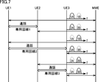
- the dedicated line used is established. For example, as shown in FIG. 1, a dedicated line 1 is established between UE1 and UE2, a dedicated line 2 is established between UE1 and UE3, and a dedicated line 3 is established between UE2 and UE3.
- the voice uttered by the user of UE1 is transmitted to UE2 and UE3 via dedicated line 1 and dedicated line 2, respectively.
- the dedicated line 1 and the dedicated line 2 are independent of each other. That is, UE1 sends data to UE2 and UE3 independently through dedicated lines 1 and 2, respectively.
- the voice uttered by the user of UE2 is transmitted to UE2 and UE3 via dedicated lines 1 and 3, respectively.
- Voices uttered by the user of UE3 are transmitted to UE1 and UE2 via dedicated lines 3 and 2, respectively.
- Each UE synthesizes and outputs the received voice from other UEs.
- UE1 synthesizes and outputs data received from UE2 and UE3 independently via dedicated lines 1 and 2, respectively.
- This voice synthesis is typically realized simply by superimposing a plurality of voice signals and outputting them to a single speaker, and does not increase the processing load associated with the voice synthesis.
- each BS 200 allocates (n-1) line component carriers to UEs existing in the cell area.
- Each dedicated line must be capable of bidirectional communication.
- uplink and downlink component carriers may be allocated, or one component carrier may be switched between uplink and downlink at predetermined intervals. Good. That is, one component carrier may be multiplexed in a time division manner.
- each of UE1 to UEn possessed by user 1 to user n has (n-1) line component carriers. Assign.
- a dedicated line using a component carrier can be established for each user with each of all other users.
- Such a dedicated line between users becomes a route through the MME 300.
- multi-party communication can be realized without installing a server for centrally managing voice data.
- a delay due to processing in the MME 300 does not occur.
- each component carrier is allocated to a dedicated line between users, so that communication can be performed while occupying the allocated bandwidth between users. Since the allocated bandwidth can be monopolized, it is possible to achieve the necessary throughput for each call between users and to perform optimum communication control according to the terminal capability. Thereby, radio resources can be used effectively.
- component carriers are allocated to each dedicated line corresponding to users, even when there is an increase or decrease (addition or deletion) of users participating in multi-party communication.
- Communication control can be performed individually in units of component carriers. Therefore, it is possible to respond more flexibly to the addition or deletion of participants.
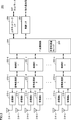
- FIG. 2 is a block diagram showing a schematic configuration of radio terminal (UE) 100 according to the present embodiment.
- UE 100 has a number of transmission / reception circuits corresponding to available component carriers as a radio unit corresponding to carrier aggregation.
- the UE 100 is equipped with a plurality of radio signal transmission / reception circuits corresponding to each of the allocated component carriers.
- the wireless terminal 100 is provided with transmitting antennas 114-1 and 114-2 for transmitting wireless signals and receiving antennas 118-1 and 118-2 for receiving wireless signals.
- a housing 150 is included.
- Case 150 includes control unit 104, signal processing unit 102, transmission units 112-1 and 112-2, and reception units 116-1 and 116-2.
- the reception antenna 118-1, the reception unit 116-1, the signal processing unit 102, the transmission unit 112-1, and the transmission antenna 114-1 correspond to a transmission / reception circuit for transmitting / receiving the first component carrier.
- Reference numeral 118-2, the reception unit 116-2, the signal processing unit 102, the transmission unit 112-2, and the transmission antenna 114-2 correspond to a transmission / reception circuit for transmitting / receiving the second component carrier.
- the signal processing unit 102 processes a radio signal transmitted / received to / from the BS 200 that manages the cell area in which the device itself is present. More specifically, the signal processing unit 102 outputs information to be transmitted to the BS 200 to the transmission units 112-1 and 112-2 in accordance with an internal command given from the control unit 104. Transmitters 112-1 and 112-2 perform encoding processing, modulation processing, up-conversion, and the like on the information received from signal processing unit 102, and transmit the resulting radio signal to corresponding transmitting antenna 114- Radiates to the outside via 1,114-2.
- receiving sections 116-1 and 116-2 perform down-conversion, demodulation processing, decoding processing, and the like on the radio signals received via corresponding receiving antennas 118-1 and 118-2, and the result The obtained information is output to the signal processing unit 102.
- the control unit 104 includes, as main components, a processor, a nonvolatile memory for holding a program executed by the processor, and a volatile memory functioning as a work memory. Further, the control unit 104 includes a multi-party communication logic 105. This logic is typically provided by the control unit 104 executing a program stored in advance. For example, modules corresponding to the multi-party communication logic 105 are stored in advance in a non-volatile memory, and a function related to multi-party communication is provided by the control unit 104 reading and executing these modules.
- the multi-party communication logic 105 provides (1) a function of notifying participation and (2) a function of notifying participation. In any case, the multi-party communication logic 105 performs processing related to addition and deletion of component carriers used for transmission / reception of radio signals with the corresponding BS 200.
- the multi-party communication logic 105 performs (1) multi-party communication using carrier aggregation at the start of communication to the UE 100 specified by the user operation as a function of notifying participation. It has a function of adding an identifier indicating that there is. At this time, the multi-party communication logic 105 requests connection to a plurality of UEs 100.
- the multi-party communication logic 105 has a function of instructing the UE 100 to make a call to the other participant's UE 100 at the same time as making a call to the participant's UE 100. More specifically, the multi-party communication logic 105 instructs one UE 100 out of a plurality of UEs 100 that requested connection to connect to the remaining UEs 100. With this function, a dedicated line is established between the UEs 100 of the participants who are not the leaders. By adding an identifier indicating multi-party communication to an incoming call, processing is distinguished from normal communication / call.
- the multi-party communication logic 105 When the communication between the multi-party communication logic 105 is instructed to make a call from another UE 100 to another UE 100 as a function to be notified of participation, the multi-party communication logic 105 automatically The function to make a call automatically. That is, the multi-party communication logic 105 requests connection to the instructed UE 100 in response to an instruction to connect to any UE 100.
- control unit 104 may be implemented as dedicated hardware (integrated circuit). In this case, in addition to the functions provided by the control unit 104, functions provided by the signal processing unit 102, the transmission units 112-1 and 112-2, and the reception units 116-1 and 116-2. The whole or a part may be integrated into one chip. Furthermore, a SoC (System-on-a-Chip) in which components such as a processor, a memory, and a controller for peripheral devices are integrated into one chip can be used.
- SoC System-on-a-Chip
- control unit 104 As an alternative configuration, all or part of the functions provided by the control unit 104, the signal processing unit 102, the transmission units 112-1 and 112-2, and the reception units 116-1 and 116-2 are implemented as software. May be.
- an instruction set installed in advance is executed by an arithmetic device (processor) such as a CPU (Central Processing Unit) or a DSP (Digital Signal Processor).
- processor such as a CPU (Central Processing Unit) or a DSP (Digital Signal Processor).
- the casing 150 further includes a display unit 152 for displaying various types of information, a microphone 154 for acquiring user's voice, a speaker 156 for reproducing received voice, and a user operation.
- An input unit 158 for displaying various types of information.
- the display unit 152 displays information related to a user (UE 100) participating in multi-person communication. More specifically, the display unit 152 displays information (telephone number, image, character information data, etc.) related to participating users during connection of multi-person communication and connection processing.
- the input unit 158 includes a touch pad, a cross key, a numeric keypad, and the like, and accepts designation of a user (UE 100) participating in multi-party communication.
- the user operates the input unit 158 to select a plurality of connection destination telephone numbers.
- simultaneous connection to a plurality of selected users (UE 100) may be performed simultaneously or individually.
- the lines may be disconnected all at once, or individual lines may be disconnected in order.
- FIG. 3 is a block diagram showing a schematic configuration of base station (BS) 200 according to the present embodiment.
- BS 200 basically has a number of transmission / reception circuits corresponding to the component carriers that can be provided. More specifically, the BS 200 includes control units 202-1 to 202-n, signal processing units 210-1 to 210-n, transmission units 212-1 to 212-n, and transmission antennas 214-1 to 214. -N, receiving units 216-1 to 216-n, and receiving antennas 218-1 to 218-n. Further, the BS 200 includes a central processing unit 204, an upper network interface (I / F) 206, and a control interface (I / F) 208.
- I / F upper network interface
- I / F control interface
- Each of the transmission / reception circuits of the BS 200 exchanges data (radio signals) with the UE 100 using the allocated component carrier. That is, each of the control units 202-1 to 202-n outputs user data, control information, management information and the like given from the central processing unit 204 to the corresponding signal processing units 210-1 to 210-n, The user data decrypted by the processing units 210-1 to 210-n is output to the central processing unit 204.
- the signal processing units 210-1 to 210-n process radio signals exchanged with the UE 100 existing in an area where the corresponding component carrier can be reached. More specifically, the signal processing units 210-1 to 210-n receive user data, control information, management information, and the like given from the corresponding control units 202-1 to 202-n and transmit them to the UE 100. The power information is output to the corresponding transmission units 212-1 to 212-n. Transmitting sections 212-1 to 212-n perform encoding processing, modulation processing, and up-conversion on information received from corresponding signal processing sections 210-1 to 210-n, and wireless signals obtained as a result thereof Are radiated to the outside via the corresponding transmitting antennas 214-1 to 214-n.
- receiving sections 216-1 to 216-n perform down-conversion, demodulation processing, and decoding processing on radio signals received via corresponding receiving antennas 218-1 to 218-n, and obtain the result.
- the information is output to the corresponding signal processing units 210-1 to 210-n.
- the central processing unit 204 includes, as main components, a processor, a nonvolatile memory for holding a program executed by the processor, and a volatile memory functioning as a work memory. Further, the central processing unit 204 includes a multi-party communication logic 205.
- the multi-party communication logic 205 is typically provided by the central processing unit 204 executing a program stored in advance. For example, modules corresponding to the multi-party communication logic 205 are stored in advance in a non-volatile memory, and the central processing unit 204 reads and executes these modules to provide functions as described later.
- the multi-party communication logic 205 executes component carrier assignment and various procedures in order to realize multi-party communication involving a plurality of UEs 100. More specifically, when the multi-party communication logic 205 receives a call including an identifier indicating multi-party communication, the multi-party communication logic 205 transfers the call to the called UE 100 while including the identifier. . Further, the multi-party communication logic 205 makes a call from the UE 100 existing in the cell area managed by the own station or the UE 100 existing in the cell area managed by another BS 200. If an identifier indicating that the call is multi-party communication is included in the call, a different component carrier is assigned to each call. That is, the multi-party communication logic 205 responds to connection requests from the UE 100 existing in the cell area provided by the own station to the other UEs 100, and a plurality of connections (component carriers) having different frequencies. Establish each.
- the multi-party communication logic 205 is used even when there are a plurality of calls including an identifier indicating multi-party communication with respect to the UE 100 existing in the cell area managed by the own station. It provides a function that can respond to any call without being busy (busy).
- central processing unit 204 may be implemented as dedicated hardware (integrated circuit).
- control units 202-1 to 202-n, signal processing units 210-1 to 210-n, transmission units 212-1 to 212-n, and All or part of the functions provided by the receiving units 216-1 to 216-n may be integrated into one chip.
- SoC in which components such as a processor, a memory, and a controller for peripheral devices are integrated into one chip can be used.
- the signal processing units 210-1 to 210-n may be implemented as software.
- an arithmetic unit such as a CPU or DSP executes a preinstalled instruction set.
- the host network interface 206 exchanges user data, control information, management information, and the like with the MME 300 managing its own station. Similarly, the control interface 208 exchanges control information with other BSs 200.
- a dedicated line establishment process will be described with reference to FIGS. 1 and 4 to 7.
- UE1 to UE3 exist in cell areas C201 to C203 provided by BS1 to BS3, respectively. That is, UE1 possessed by user 1 can communicate with BS1 via a radio signal.
- UE2 possessed by user 2 can communicate with BS2 via a radio signal
- UE3 possessed by user 3 can communicate with BS3 via a radio signal.
- a plurality of UEs 100 participating in multi-party communication may exist in a single BS 200.
- FIG. 4 is an example of a user interface provided by UE 100 used in communication system 1 according to the present embodiment.
- the display unit 152 of the UE 100 displays a list of users who can be notified of participation in multi-party communication.
- the user operates the input unit 158 of the UE 100 to select a user who should participate in the multi-person communication.
- the display unit 152 displays four users (A, B, C, and D).
- the user of UE1 has two users (A And Mr. B). Assume that Mr. A corresponds to the user 2 who owns the UE 2, and Mr. B corresponds to the user 3 who owns the UE 3. Then, as shown in FIG.
- UE1 when the user presses “call”, UE1 makes a call to UE2 and UE3 in parallel. At this time, UE1 transmits to UE2 a parameter instructing “calling to UE3” together with the call. That is, the private lines 1 and 2 are established by the initiative of the UE 1, and the UE 2 that receives the instruction from the UE 1 establishes the private line 3.
- FIG. 5 is a schematic diagram illustrating an example of component carrier allocation corresponding to FIG. 1
- FIG. 6 is a sequence diagram illustrating processing related to component carrier allocation illustrated in FIG. 5,
- FIG. It is a schematic diagram which shows the dedicated line between UE using the component carrier shown.
- UE1 when the user selects a user who participates in multi-party communication (sequence SQ2), UE1 calls UE2 and UE3 (sequence SQ10). That is, UE1 that is the first radio terminal requests connection to UE2 and UE3 that are the second and third radio terminals.
- BS1 which provides a cell area in which UE1 exists, allocates component carrier 1A for communication between UE1 and UE2, and UE1 and UE3 Component carrier 1B is assigned to the communication between the two (sequence SQ12).
- UE1 starts the radio
- the second connection (component carrier 1B) having a frequency different from that of the first connection (component carrier 1A) is established.
- the BS 1 controls a modulation method, a MIMO (Multiple Input Multiple Output) method, and the like according to the throughput required in each of the component carriers 1A and 1B and the capability of the UE1.
- a modulation method a MIMO (Multiple Input Multiple Output) method, and the like according to the throughput required in each of the component carriers 1A and 1B and the capability of the UE1.
- MIMO Multiple Input Multiple Output
- the call from UE1 to UE2 includes a parameter for instructing a call from UE2 to UE3. That is, UE1 instructs UE2 to connect to UE3.
- the BS 1 transmits a call from the UE 1 to the UE 2 via the mobile management device (MME) 300 to the BS 2 that provides the cell area where the UE 2 possessed by the user 2 exists.
- MME mobile management device
- a parameter for instructing a call from UE2 to UE3 is transmitted (sequence SQ14).
- BS1 transmits a call from UE1 to UE3 via MME 300 to BS3 that provides a cell area in which UE3 owned by user 3 is present (sequence SQ14).
- This call includes an identifier indicating that the communication is multi-party communication using carrier aggregation.
- BS2 When BS2 receives an incoming call including an identifier indicating that the communication is multi-party from UE1, via MME300, BS2 transfers the incoming call to UE2 (sequence SQ20). At this time, BS2 allocates component carrier 2A to UE2 in order to transfer this incoming call (sequence SQ16). BS2 controls the modulation scheme and MIMO scheme of component carrier 2A so as to match the throughput of component carrier 1A included in the dedicated line between UE1 and UE2 (sequence SQ18). That is, BS1 corresponding to UE1 and BS2 corresponding to UE2 are controlled so that transmission performance substantially matches between component carrier 1A and component carrier 2A. Thereby, the transmission quality of the dedicated line between UE1 and UE2 can be equalized. Therefore, negotiation is performed between BS1 and BS2, and the component carriers assigned by each are optimized.
- the BS 2 reduces the communication rate and changes the component
- the BS 1 is notified so that the resources allocated to the carrier 1A are reduced.
- BS1 notifies that the modulation scheme or the MIMO scheme is changed in order to reduce the throughput of component carrier 1A.
- BS1 changes the resource allocated to component carrier 1A, the modulation scheme, and the like so as not to exceed the throughput that can be achieved by component carrier 2A.
- BS 3 transfers the incoming call to UE 3 (sequence SQ30).
- BS 3 assigns component carrier 3A to UE 3 to transfer the incoming call (sequence SQ26).
- BS1 and BS3 are such that the modulation schemes and MIMO schemes of the corresponding component carriers are such that the respective throughputs of component carriers 1B and 3A included in the dedicated line between UE1 and UE3 are equal to each other. Are controlled (sequence SQ30).
- UE2 when UE2 receives a parameter instructing “calling to user 3” from UE1, UE2 automatically sends a call with an identifier indicating that the communication is multi-party communication using carrier aggregation to UE3. (Sequence SQ40). That is, UE2 requests connection to UE3 in response to an instruction from UE1.
- BS2 that provides a cell area in which UE2 exists allocates component carrier 2B for communication between UE2 and UE3. And UE2 starts the radio
- the BS 2 transmits a call from the UE 2 to the UE 3 via the MME 300 to the BS 3 that provides the cell area where the UE 3 possessed by the user 3 exists.
- This call includes an identifier indicating that the communication is multi-party communication using carrier aggregation.
- BS2 that provides the cell area in which UE2 exists assigns component carrier 2B to communication between UE2 and UE3 (sequence SQ42). And UE2 starts the radio
- BS2 transmits a call from UE2 to UE3 via BS 300 to BS3 that provides a cell area where UE3 possessed by user 3 is present (sequence SQ44).
- This call includes an identifier indicating that the communication is multi-party communication using carrier aggregation.
- BS3 When BS3 receives an incoming call including an identifier indicating that the communication is multi-party from UE2, via MME300, BS3 transfers the incoming call to UE3 (sequence SQ50). At this time, BS 3 assigns component carrier 3B to UE 3 in order to transfer the incoming call (sequence SQ46). That is, the BS 3 corresponding to the UE 3 has a connection (component carrier 3A) associated with the communication between the UE 3 and UE 1 and a connection (component carrier 3A) associated with the communication between the UE 3 and the UE 2 with a frequency different from that of the component carrier 3A. 3B).
- BS2 and BS3 are such that the modulation schemes and MIMO schemes of the corresponding component carriers are set so that the respective throughputs of component carriers 2B and 3B included in the dedicated line between UE2 and UE3 are equal to each other. Is controlled (sequence SQ48).
- the relationship between the UE after the establishment of the dedicated line and the assigned component carrier is as shown in FIG. Similarly, when there are n users participating in multi-party communication, (n-1) component carriers are allocated to each user, and dedicated lines are connected to all other users. Can be established.
- the dedicated line between the UEs 100 in the multi-party communication described below is established by allocating component carriers among all the UEs 100. Also, when the BS 200 receives a call including an identifier indicating that the communication is between two parties from the UE 100 existing in the cell area managed by the own station, the BS 200 receives different components of the call destination. By assigning carriers, a dedicated line using carrier aggregation is established.
- UE1 to UE4 As an example, a case where four-way communication involving users 1 to 4 (UE1 to UE4) is described will be described.
- UE1 possessed by user 1 makes a sequential call in the order of UE2, UE3, and UE4. Then, UE1 instructs UE2 to make a call to UE3 and UE4 that can connect to UE1. This establishes a connection between UEs other than the leader UE1.
- FIG. 8 is a schematic diagram showing a procedure when performing communication between four parties in communication system 1 according to the present embodiment.
- UE1 calls sequentially in the order of UE2, UE3, and UE4.
- the BS providing the cell area in which UE1 exists receives a call including an identifier indicating that the communication is multi-user communication from UE1, each of the calls to UE2, UE3, and UE4 is mutually Assign different component carriers and establish a dedicated line using carrier aggregation.
- UE1 instructs UE2 to make a call according to the presence / absence of responses from UE3 and UE4. For example, if there is a response from both UE3 and UE4, UE1 instructs UE2 to make a call to UE3 and UE4, respectively.
- the UE 2 receiving the call instruction from the UE 1 makes a call to the instructed UE following the response to the call from the UE 1.
- the UE 2 also transmits a call instruction to other UEs to any one of the instructed call destination UEs.
- This call instruction includes the telephone number of the target UE. In this way, a UE that has received a call instruction from another UE repeats a call to another UE. If the number of destinations designated finally becomes one, it is possible to establish the necessary number of dedicated lines between a plurality of designated UEs.
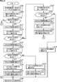
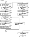
- FIG. 9 and FIG. 10 are flowcharts in the UE serving as the leader showing the procedure for establishing the connection related to the multi-party communication shown in FIG.
- FIG. 11 is a flowchart in a UE other than the leader showing a procedure for establishing a connection related to the multi-party communication shown in FIG. In the flowcharts shown in FIG. 9 to FIG. 11, it is assumed that the user 1 having the UE 1 takes the lead and starts multi-party communication.
- Step S102 This user selection method is performed by inputting the telephone number of the corresponding UE.
- the UE 1 possessed by the user 1 determines the order in which calls are made to the selected UE 2 to UE 4, and makes a call to one UE determined as the first call destination (step S 104).
- a method for determining the order of making a call for example, a method of determining according to the order in which a user who is a leader inputs a telephone number for selecting another user may be considered.
- a call is first made to UE2.
- an identifier indicating that the communication is multi-party communication is added to the call from UE1 to UE2.
- communication is sequentially established according to the following procedure.
- UE1 determines whether or not there is a response from UE2 after the call to UE2 (step S110). If there is a response from UE2 (YES in step S110), UE1 establishes a connection with UE2 (step S112). That is, the BS corresponding to the cell in which UE1 exists and the BS corresponding to the cell in which UE2 exist allocate component carriers for establishing a dedicated line between UE1 and UE2 to UE1 and UE2, respectively. .
- UE1 calls the UE corresponding to the next order.
- UE1 makes a call to UE3, which is the next call destination (step S114).
- An identifier indicating that the communication is multi-party communication is also added to the call from UE1 to UE3.
- UE1 determines whether or not there is a response from UE3 after the call to UE3 (step S120). If there is a response from UE3 (YES in step S120), UE1 establishes a connection with UE3 (step S122). That is, the BS corresponding to the cell in which UE1 exists and the BS corresponding to the cell in which UE3 exists allocate component carriers for establishing a dedicated line between UE1 and UE3 to UE1 and UE3, respectively. .
- UE1 calls the UE corresponding to the next order.
- UE1 makes a call to UE4, which is the next call destination (step S124).
- An identifier indicating that the communication is multi-party communication is also added to the call from UE1 to UE4.
- UE1 determines whether or not there is a response from UE4 after the call to UE4 (step S130). If there is a response from UE4 (YES in step S130), UE1 establishes a connection with UE4 (step S132). That is, the BS corresponding to the cell where UE1 exists and the BS corresponding to the cell where UE4 exists allocates component carriers for establishing a dedicated line between UE1 and UE4 to UE1 and UE4, respectively. .
- UE1 determines that it can connect to all of the selected UE2 to UE4. Subsequently, UE1 notifies UE2 of identification information (telephone numbers) of UE3 and UE4, and instructs UE2 to make a call to UE3 and UE4 (step S134). And UE1 starts the telephone call between each of UE2, UE3 and UE4 (step S136).
- UE1 maintains a state of waiting for an incoming call from another UE so that a response from a new user can be accepted even after starting a call with UE2, UE3, and UE4 (step S190).
- UE1 can connect to UE2 and UE3 among the selected UE2 to UE4, and connection to UE4 is not possible. Judge that it is possible. Subsequently, UE1 notifies UE2 of identification information (telephone number) of UE3, and instructs UE2 to make a call to UE3 (step S138). And UE1 starts the telephone call between each of UE2 and UE3 (step S140). Furthermore, UE1 maintains the state of waiting for an incoming call from another UE so that a response from a new user can be accepted (step S190).
- UE1 determines that it cannot connect to UE3. Then, UE1 makes a call to UE4, which is the next call destination (step S126).
- UE1 determines whether or not there is a response from UE4 (step S150). If there is a response from UE4 (YES in step S150), UE1 establishes a connection with UE4 (step S152).
- UE1 determines that it can connect to UE2 and UE4 among the selected UE2 to UE4, and cannot connect to UE3. Subsequently, UE1 notifies UE2 of identification information (telephone number) of UE4, and instructs UE2 to make a call to UE4 (step S154). And UE1 starts the telephone call between each of UE2 and UE4 (step S156). Furthermore, UE1 maintains the state of waiting for an incoming call from another UE so that a response from a new user can be accepted (step S190).
- UE1 determines that only UE2 among the selected UE2 to UE4 can be connected. And UE1 starts the telephone call between UE2 (step S158). Furthermore, UE1 maintains the state of waiting for an incoming call from another UE so that a response from a new user can be accepted (step S190).
- UE1 determines that it cannot connect to UE2. Then, UE1 makes a call to UE3, which is the next call destination (step S116).
- UE1 determines whether or not there is a response from UE3 (step S160). If there is a response from UE3 (YES in step S160), UE1 establishes a connection with UE3 (step S162). That is, the BS corresponding to the cell in which UE1 exists and the BS corresponding to the cell in which UE3 exists allocate component carriers for establishing a dedicated line between UE1 and UE3 to UE1 and UE3, respectively. . Then, UE1 makes a call to UE4, which is the next call destination (step S164).
- UE1 determines whether or not there is a response from UE4 (step S170). If there is a response from UE4 (YES in step S170), UE1 establishes a connection with UE4 (step S172).
- UE1 determines that it can connect to UE3 and UE4 among the selected UE2 to UE4, and cannot connect to UE2. Subsequently, UE1 notifies UE3 of identification information (telephone number) of UE4, and instructs UE3 to make a call to UE4 (step S174). And UE1 starts the telephone call between each of UE3 and UE4 (step S176). Furthermore, UE1 maintains the state of waiting for an incoming call from another UE so that a response from a new user can be accepted (step S190).
- UE1 determines that only UE3 among the selected UE2 to UE4 can be connected. And UE1 starts the telephone call between UE3 (step S178). Furthermore, UE1 maintains the state of waiting for an incoming call from another UE so that a response from a new user can be accepted (step S190).
- UE1 determines that it cannot connect to UE3. Then, UE1 makes a call to UE4, which is the next call destination (step S166).
- UE1 determines whether there is a response from UE4 (step S180). If there is a response from UE4 (YES in step S180), UE1 establishes a connection with UE4 (step S182). At this time, UE1 determines that only UE4 among the selected UE2 to UE4 can be connected. And UE1 starts the telephone call between UE4 (step S184). Furthermore, UE1 maintains the state of waiting for an incoming call from another UE so that a response from a new user can be accepted (step S190).
- UE1 determines that none of the selected UE2 to UE4 can be connected. Then, UE1 disconnects the line (step S186).
- UE1 may instruct UE2 to connect to a plurality of UEs (UE3 and UE4).
- UE1 determines whether or not there is a response from UE3 and UE4 in response to a request for connection to UE3 and UE4, and on the condition that there is a response from UE3 and UE4, to UE2 It instructs the connection to UE3 and UE4. Therefore, when UE1 requests connection to UE2 to UE4, it requests connection to UE2, and after receiving a response from UE2, requests connection to UE3 and UE4.
- step S200 determines whether an incoming call has been received from another UE. If no incoming call has been received (NO in step S200), the process of step S200 is repeated.
- the UE determines whether or not the received incoming call includes an identifier indicating that the communication is multi-party communication (step S202).
- the UE executes a response procedure for the received incoming call, and issues the incoming call.
- One-to-one communication is established with the original UE (step S206). Then, a call is started with the source UE.
- the UE executes a response procedure for the received incoming call, and sends the incoming call.
- a connection as multi-party communication is established with the original UE (step S208).
- a call is started with the source UE.
- the UE determines whether or not the received incoming call includes an instruction to make a call to another UE (step S210).
- the UE can receive an incoming call from a new user.
- the state of waiting for an incoming call is maintained (step S212).
- the UE determines whether there are a plurality of call destinations instructed (step S214). .
- UE1 calls the instructed call destination (step S216). Thereafter, the UE waits for a response from the callee UE and establishes a connection with the callee (step S218). Then, the UE starts a call with the callee UE.
- any UE that is instructed as a call destination is determined to be connectable by UE1 corresponding to the leader. Therefore, basically, a response is obtained from the callee UE. Further, the UE maintains a state of waiting for an incoming call from another UE so that an incoming call from a new user can be accepted (step S212).
- UE1 calls all of the designated call destinations all at once (step S220). . Subsequently, the UE notifies identification information (telephone number) of a UE other than the UE among the designated call destinations to any one UE among the designated call destinations. At the same time, it instructs the arbitrary one UE to make a call to the other UE (step S222).
- step S222 is a process for repeating outgoing calls hierarchically between UEs participating in multi-party communication. This process is sequentially executed according to the number of UEs participating in multi-party communication, so that dedicated lines are established for all combinations of UEs.
- any UE that is instructed as a call destination is determined to be connectable by the UE 1 corresponding to the leader, basically, the process of establishing this dedicated line is not interrupted.
- the UE waits for a response from each UE that is a call destination, and establishes a connection with the call destination (step S224). Then, the UE starts a call with the callee UE. Further, the UE maintains a state of waiting for an incoming call from another UE so that an incoming call from a new user can be accepted (step S212).
- Multi-party communication can be realized by the UE corresponding to the leader and other UEs performing the processing as described above.
- UEi (1 ⁇ i ⁇ n) corresponding to user i makes a call to UE (i + 1) to UEn corresponding to user (i + 1) to user n, respectively.
- UEi instructs UE (i + 1) to call UE (i + 2) to UEn.
- Procedure for establishing a dedicated line (2)> In the above-described procedure for establishing a dedicated line, an example in which a method in which a UE serving as a leader tries to connect sequentially to a plurality of UEs serving as participants has been shown. In this example, a process of instructing a UE having a higher priority to connect to another UE is sequentially repeated. This method has an advantage that the process can be simplified because the UE to be instructed to connect is determined in advance. On the other hand, if a response from the UE instructing the connection cannot be obtained, Processing may be interrupted.
- a method may be adopted in which calls are made simultaneously to a plurality of users (UEs) participating in multi-party communication, and connection processing is sequentially performed in the order of quick response. According to this method, the procedure for connecting a dedicated line can be dynamically changed according to the situation of each UE.
- the UE that is the leader makes a call to a plurality of UEs all at once, and gives a call instruction to another UE to the UE that has responded earliest among them. For example, when UE1 requests connection to UE2 to UE4, UE1 requests connection to UE2 to UE4 all at once. For example, in the case of the four-party communication as described above, the leader UE1 makes a call to the UE2, UE3, and UE4 all at once.
- the BS providing the cell area in which UE1 is present receives a call including an identifier indicating that the communication is multi-party from UE1, component BSs different from each other for each call to UE2, UE3, and UE4. To establish a dedicated line using carrier aggregation.
- UE1 confirms the response of the UE that responded earliest to UE1 (UE3 as an example here) among UE2, UE3, and UE4 that have called all at once, and then participates in multi-party communication.
- the identification information (telephone number) of all other UEs is notified to the UE (UE3) that responded earliest.
- UE3 makes a call to all UEs (in this example, UE2 and UE4) for which no dedicated line has been established with the own terminal among all other UEs participating in multi-party communication.
- a dedicated line between UEs is established. That is, if UE2 is the earliest responding to UE3 among UE2 and UE4 that are simultaneously called from UE3, UE3 identifies each identification information (telephone number) of all other UEs participating in the call. ) To UE2. UE2 makes a call to all UEs (in this example, UE4) for which a dedicated line is not established with the own terminal among all other UEs participating in multi-party communication.
- FIG. 12 is a flowchart in the UE that takes the lead in the process of sequentially performing the connection process in the order of quick response.
- FIG. 13 is a flowchart in the UE other than the leader in the process of sequentially performing the connection process in the order of quick response. In the flowcharts shown in FIG. 9 to FIG. 11, it is assumed that the user 1 having the UE 1 takes the lead and starts multi-party communication.
- Step S302 This user selection method is performed by inputting the telephone number of the corresponding UE.
- the UE1 possessed by the user 1 makes a call to the selected UE2 to UE4 all at once (step S304). At this time, an identifier indicating that the communication is multi-party communication is added to each signal of the call from UE1 to UE2 to UE4.
- UE1 determines whether there is a response from any of the UEs after the simultaneous call to UE2 to UE4 (step S306). If there is a response from any UE (YES in step S306), UE1 determines which UE responded to the call earliest (step S308).
- UE1 When UE2 answers the call earliest (in the case of “UE2” in step S308), UE1 establishes a connection with UE2 (step S310). That is, the BS corresponding to the cell in which UE1 exists and the BS corresponding to the cell in which UE2 exist allocate component carriers for establishing a dedicated line between UE1 and UE2 to UE1 and UE2, respectively. .
- the UE 1 identifies the identification information (telephone number) of each of the remaining UEs (UE 3 and UE 4 in this example) excluding the UE that responded to the call earliest among the plurality of UEs selected for the multi-party communication.
- UE2 is instructed to call UE2 (UE3 and UE4) (step S312).
- UE1 sequentially establishes a connection with another UE that has responded to the call subsequent to UE2 (step S314). And UE1 starts a telephone call between each of UE which established the connection (step S316).
- UE1 maintains a state of waiting for an incoming call from another UE so that a response from a new user can be accepted even after starting a call with any UE (step S318).
- UE1 When UE3 answers the call earliest (in the case of “UE3” in step S308), UE1 establishes a connection with UE3 (step S320). That is, the BS corresponding to the cell in which UE1 exists and the BS corresponding to the cell in which UE3 exists allocate component carriers for establishing a dedicated line between UE1 and UE3 to UE1 and UE3, respectively. .
- UE1 has identification information (telephone number) of each of the remaining UEs (UE2 and UE4 in this example) excluding the UE that responded to the call earliest among a plurality of UEs selected for multi-party communication.
- identification information phone number
- UE3 and instructing UE3 to make a call to the UEs (UE2 and UE4) step S322).
- UE1 successively establishes a connection with another UE that responded to the call subsequent to UE3 (step S324). And UE1 starts a telephone call between each of UE which established the connection (step S326).
- UE1 maintains a state of waiting for an incoming call from another UE so that a response from a new user can be accepted even after starting a call with any UE (step S318).
- UE1 When UE4 answers the call earliest (in the case of “UE4” in step S308), UE1 establishes a connection with UE4 (step S330). That is, the BS corresponding to the cell where UE1 exists and the BS corresponding to the cell where UE4 exists allocates component carriers for establishing a dedicated line between UE1 and UE4 to UE1 and UE4, respectively. .
- UE1 has identification information (telephone number) of each of the remaining UEs (UE2 and UE3 in this example) excluding the UE that responded to the call earliest among a plurality of UEs selected for multi-party communication.
- identification information phone number
- UE4 and instructing UE4 to make a call to the UEs (UE2 and UE3) step S332).
- UE1 successively establishes a connection with another UE that has responded to the call subsequent to UE4 (step S334). And UE1 starts a telephone call between each of UE which established the connection (step S336).
- UE1 maintains a state of waiting for an incoming call from another UE so that a response from a new user can be accepted even after starting a call with any UE (step S318).
- UE1 determines that none of the selected UE2 to UE4 can be connected. Then, UE1 disconnects the line (step S340).
- a UE that is not the lead determines whether or not an incoming call has been received from another UE (step S400). If no incoming call has been received (NO in step S400), the process of step S400 is repeated.
- the UE 2 determines whether or not the received incoming call includes an identifier indicating that the communication is multi-party communication (step S402).
- the UE 2 executes a response procedure for the received incoming call, and sends the incoming call.
- One-to-one communication is established with the original UE (step S406). Then, a call is started with the source UE.
- the UE 2 executes a response procedure for the received incoming call, and sends the incoming call.
- a connection as multi-party communication is established with the original UE (step S408).
- UE2 starts a telephone call between UE of origin.
- UE2 determines whether or not the received incoming call includes an instruction to make a call to another UE (step S410).
- UE2 can receive an incoming call from a new user so that it can accept an incoming call from a new user.
- the state of waiting for an incoming call is maintained (step S412).
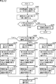
- UE2 When the received incoming call includes an instruction to make a call to another UE (YES in step S410), UE2 receives all UEs instructed to make the call (UE3 and UE4 in this example). Are simultaneously called (step S414). An identifier indicating that the communication is multi-party communication is also added to each signal related to the call.
- UE2 determines whether there is a response from any of the UEs after the simultaneous call (step S416). If there is a response from any UE (YES in step S416), UE2 determines which UE responded to the call earliest (step S418).
- UE2 When UE3 answers the call earliest (in the case of “UE3” in step S418), UE2 establishes a connection with UE3 (step S420). That is, the BS corresponding to the cell where UE2 exists and the BS corresponding to the cell where UE3 exists allocate component carriers for establishing a dedicated line between UE2 and UE3 to UE2 and UE3, respectively. .
- UE2 sends the identification information (telephone number) of the remaining UEs (UE4 in this example) to the UE3 except for the UE that responded to the call earliest among the plurality of UEs selected for the multi-party communication.
- the UE 3 is instructed to make a call to the UE (UE 4) (step S422).
- UE2 successively establishes a connection with other UEs that responded to the call subsequent to UE3 (step S424). And UE2 starts a telephone call between each of UE which established the connection (step S426).
- the UE 2 maintains a state of waiting for an incoming call from another UE so that an incoming call from a new user can be accepted (step S412).
- UE 4 when UE 4 answers the call earliest (in the case of “UE 4” in step S418), UE 2 establishes a connection with UE 4 (step S430). That is, the BS corresponding to the cell in which UE2 exists and the BS corresponding to the cell in which UE4 exists allocate component carriers for establishing a dedicated line between UE2 and UE4 to UE2 and UE4, respectively. .
- UE2 sends the identification information (telephone number) of the remaining UEs (UE3 in this example) other than the UE that responded to the call earliestly among the plurality of UEs selected for the multi-party communication to UE4.
- the UE 4 is instructed to make a call to the UE (UE 3) (step S432).
- UE2 successively establishes a connection with another UE that has responded to the call subsequent to UE4 (step S434). And UE2 starts a telephone call between each of UE which established the connection (step S436).
- the UE 2 maintains a state of waiting for an incoming call from another UE so that an incoming call from a new user can be accepted (step S412).
- step S412 if there is no response from any of the UEs (NO in step S416), the above process is skipped and the process of step S412 is executed.
- the main body that executes the process related to multi-party communication according to the present embodiment may be present in any one of the communication systems, and the implementation form includes a system scale, a system hierarchy configuration, a network configuration, It is possible to design appropriately according to various situations such as the cooperation form of other systems.
- the communication system according to the present embodiment establishes a dedicated line for each user (wireless terminal) when performing multi-party communication.
- multi-party communication can be realized in real time with almost no delay without installing a server.
- by assigning component carriers using carrier aggregation it is possible to select optimal communication control between users.
- resource blocks can be allocated over a plurality of bands.
- component carriers are allocated to dedicated lines between users, so that communication between each user can be performed while occupying the allocated bandwidth.
- the allocated bandwidth can be monopolized, it is possible to achieve the required throughput for each call between users and to perform optimal communication control (modulation scheme or MIMO scheme) according to the terminal capability. it can. Thereby, radio resources can be used effectively.
- a communication method according to an aspect of the present invention includes several preferred forms as follows.
- the first wireless terminal sends data to the second and third wireless terminals independently via the first and second connections, respectively, and independently via the first and second connections.
- the data received from the second and third wireless terminals is combined and output.
- the base station corresponding to the third wireless terminal has a fifth connection associated with the communication between the third wireless terminal and the first wireless terminal, the third wireless terminal, Further comprising establishing a sixth connection of a different frequency than the fifth connection associated with the communication with the two wireless terminals.
- the base station corresponding to the first wireless terminal and the base station corresponding to the second wireless terminal have substantially the transmission performance between the first connection and the third connection. It further includes the step of controlling to match.
- the communication method further includes a step in which the first wireless terminal determines whether or not there is a response from the third wireless terminal to the request for connection to the third wireless terminal, The step of instructing the second wireless terminal to connect to the third wireless terminal is executed on condition that there is a response from the third wireless terminal.
- the step of instructing the second wireless terminal to connect to the third wireless terminal includes the step of instructing connection to a plurality of third wireless terminals.
- the step of the first wireless terminal requesting connection to the second and third wireless terminals includes a step of requesting connection to the second wireless terminal and a response from the second wireless terminal. And requesting a connection to the third wireless terminal.
- the step of the first wireless terminal requesting connection to the second and third wireless terminals includes a step of simultaneously requesting connection to the second and third wireless terminals.
- UE wireless terminal
- 102 wireless terminal
- 104 202 control unit
- 105 205 interpersonal communication logic
- 112 212 transmission unit
- 114 214 transmission antenna
- 116 216 reception unit
- 118 218 receiving antenna
- 150 housing 152 display unit, 154 microphone, 156 speaker, 158 input unit
- 200 base station (BS) base station
- 204 central processing unit
- 206 host network interface
- 208 control interface 300 mobile management device ( MME), 400 core network.
- MME mobile management device
Landscapes
- Engineering & Computer Science (AREA)
- Computer Networks & Wireless Communication (AREA)
- Signal Processing (AREA)
- Mobile Radio Communication Systems (AREA)
- Telephone Function (AREA)
Abstract
複数の無線端末の間で多者間通信を行なうための通信方法が提供される。通信方法は、第1の無線端末が、第2および第3の無線端末への接続を要求するステップと、第1の無線端末に対応する基地局が、第1の無線端末と第2の無線端末との通信に関連付けられた第1の接続と、第1の無線端末と第3の無線端末との通信に関連付けられた第1の接続とは異なる周波数の第2の接続とを確立するステップと、第1の無線端末が、第2の無線端末に対して第3の無線端末への接続を指示するステップと、第2の無線端末が、第1の無線端末からの指示に応答して、第3の無線端末への接続を要求するステップと、第2の無線端末に対応する基地局が、第2の無線端末と第1の無線端末との通信に関連付けられた第3の接続と、第2の無線端末と第3の無線端末との通信に関連付けられた第3の接続とは異なる周波数の第4の接続を確立するステップとを含む。
Description
本発明は、多者間通信が可能な、通信方法、通信システム、無線端末、および基地局に関する。
現在、3GPP(Third Generation Partnership Project)は、次世代通信方式である、LTE(Long Term Evolution:(第3世代の)長期進化)について仕様化を進めている。さらに、LTEを発展させた規格であるLTE-A(LTE-Advanced)についても仕様化の検討が行われている。
LTE-Aでは、LTEに比較してより高速かつ大容量の通信を実現することが要求されている。そのため、LTE-Aは、LTEに比較してより広帯域な周波数範囲をサポートすることとされている。現在までの検討によれば、LTEの最大送信帯域幅が20MHzであるのに対して、LTE-Aの最大送信帯域幅は100MHzまで拡張されることとされている。
しかしながら、世界各国の電波利用状況を鑑みると、連続した広域の周波数帯域をLTE-A用として確保することは容易ではない。また、LTEとのバックワード・コンパチビリィティ(後方互換性)を可能な限り維持する必要もある。そこで、キャリアアグリゲーション(Carrier Aggregation;CA)という無線通信技術の導入が検討されている。このキャリアアグリゲーションでは、LTEの最大送信帯域幅である20MHzに相当するキャリアを複数まとめて利用することで、最大送信帯域幅を100MHzまで拡張する。このような20MHzまでのキャリアは、コンポーネントキャリア(Component Career;CC)と称される。
このようなキャリアアグリゲーションを用いることで、基地局と移動局(端末:User Equipment)との間で高速かつ大容量の通信を実現する。なお、このキャリアアグリゲーションについては、3GPP RAN1#53b会合にて合意された(非特許文献1の“5.5 Carrier Aggregation”など参照)。
ところで、無線端末を用いて、1対Nのグループ通信を提供するPoC(Push-to-Talk over Cellular)というサービスが提案されている。このようなサービスでは、サーバ側から発言権を与えられた無線端末が音声データをサーバへ送信し、サーバが、送信された音声データを接続している他の無線端末に対してほぼリアルタイムに配信する。このように、複数の無線端末の間でグループ通話(多者間通信)を実現する場合には、無線回線を介して接続しているサーバとの間で複数の無線端末がそれぞれ通信を行なうとともに、当該サーバは、接続している他の無線端末に対して音声データなどを送信する。
3GPP Organizational Partners,"3rd Generation Partnership Project;Technical Specification Group Radio Access Network;Evolved Universal Terrestrial Radio Access (E-UTRA) and Evolved Universal Terrestrial Radio Access Network(E-UTRAN); Overall description;Stage 2(Release 10)",3GPP TS 36.300 V10.3.0 (2011-03)
上述したPoCのような発言権を与えられた無線端末のみが音声データを送信できるようなシステムではなく、電話会議システムのようなそれぞれの無線端末が任意のタイミングで音声データを送信できるようなシステムがより好ましい。この場合、上述のようなシステムを発展させた形態として、それぞれの無線端末と接続されるサーバを設置し、当該サーバが、無線回線を介してそれぞれの無線端末から伝送された音声データを合成し、当該合成した音声データをそれぞれの無線端末へ配信するような構成が想定される。しかしながら、このような構成を採用した場合には、複数の無線端末からの音声データを順次合成して音声を生成する必要があり、サーバ内での処理による遅延が生じる。そのため、この構成は、電話会議システムのような複数の無線端末のユーザが同時通話するようなシステムには不向きであり、また、処理能力の高いサーバが必要になる。
そこで、本発明は、かかる問題を解決するためになされたものであり、その目的は、音声データを合成するようなサーバを不要としつつ、多者間通信を実現する、通信方法、通信システム、無線端末、および基地局を提供することである。
本発明のある局面に従えば、複数の無線端末の間で多者間通信を行なうための通信方法を提供する。通信方法は、第1の無線端末が、第2および第3の無線端末への接続を要求するステップと、第1の無線端末に対応する基地局が、第1の無線端末と第2の無線端末との通信に関連付けられた第1の接続と、第1の無線端末と第3の無線端末との通信に関連付けられた第1の接続とは異なる周波数の第2の接続とを確立するステップと、第1の無線端末が、第2の無線端末に対して第3の無線端末への接続を指示するステップと、第2の無線端末が、第1の無線端末からの指示に応答して、第3の無線端末への接続を要求するステップと、第2の無線端末に対応する基地局が、第2の無線端末と第1の無線端末との通信に関連付けられた第3の接続と、第2の無線端末と第3の無線端末との通信に関連付けられた第3の接続とは異なる周波数の第4の接続を確立するステップとを含む。
本発明の別の局面に従えば、多者間通信を行なう通信システムを提供する。通信システムは、複数の無線端末と、所定のセルエリアを提供する複数の基地局とを含む。無線端末は、複数の無線端末への接続を要求するための手段と、接続を要求した複数の無線端末のうち1つの無線端末に対して、残りの無線端末への接続を指示するための手段と、いずれかの無線端末への接続の指示に応答して、指示された無線端末への接続を要求するための手段とを含む。基地局は、基地局が提供するセルエリアに存在している無線端末からの複数の無線端末への接続要求に応答して、周波数が互いに異なる複数の接続をそれぞれ確立するための手段を含む。
本発明のさらに別の局面に従えば、多者間通信が可能な無線端末を提供する。無線端末は、他の複数の無線端末への接続を要求するための手段を含む。無線端末が存在しているセルエリアを提供する基地局は、複数の無線端末への接続要求に応答して、周波数が互いに異なる複数の接続をそれぞれ確立する。無線端末は、さらに、接続を要求した複数の無線端末のうち1つの無線端末に対して、残りの無線端末への接続を指示するための手段と、いずれかの無線端末への接続の指示に応答して、指示された無線端末への接続を要求するための手段とを含む。
本発明のさらに別の局面に従えば、多者間通信が可能な基地局を提供する。基地局は、提供するセルエリアに存在している無線端末からの複数の無線端末への接続要求に応答して、周波数が互いに異なる複数の接続をそれぞれ確立するための手段を含む。
本発明によれば、音声データを合成するようなサーバを不要としつつ、多者間通信を実現できる。
本発明の実施の形態について、図面を参照しながら詳細に説明する。なお、本発明はこれら実施の形態に何ら限定されるものではなく、その趣旨を逸脱しない範囲において、種々の態様として実施可能である。また、図中の同一または相当部分については、同一符号を付してその説明は繰り返さない。
<1.システム構成>
まず、本発明の実施の形態に従う通信システムの典型的な構成について説明する。
まず、本発明の実施の形態に従う通信システムの典型的な構成について説明する。
図1は、本発明の実施の形態に従う通信システム1の全体構成を示す模式図である。典型的な一例として、通信システム1は、LTE方式またはLTE-A方式に従う通信方式をサポートしているとする。
図1を参照して、通信システム1は、移動局である無線端末(以下「UE(User Equipment)」とも称す。)100-1~100-3と、複数の基地局(Broadcast Station:以下「BS」とも称す。)200-1~200-3と、制御装置であるモバイルマネージメント装置(Mobility Management Entity:以下「MME」とも称す。)300と、コアネットワーク400とを含む。
UE100-1~100-3(以下「UE100」とも総称する。)の各々は、典型的には、携帯電話、PDA(Personal Digital Assistant)、データ通信端末などであり、いずれかのBSを介して相手先とデータを遣り取りする。
BS200-1~200-3(以下「BS200」とも総称する。)の各々は、周波数の異なる互いに独立した複数の無線信号を送受信可能となっている。すなわち、BS200は、キャリアアグリゲーションをサポートしているとし、後述するように、1つのUE100との間で複数のコンポーネントキャリアを用いてデータを遣り取りする。
LTE方式またはLTE-A方式に従うキャリアアグリゲーションでは、一般的には、複数のコンポーネントキャリアを用いて一連のデータを送受信することが想定されている。本実施の形態に従う通信システムでは、単一のUE100に対して、互いに独立してデータを送受信するための、1または複数のコンポーネントキャリアが割り当てられる。このようなコンポーネントキャリアの割り当てを採用することで、単一のUE100から他の複数のUE100との間で、それぞれ並列的に通信を行なうことができる。
図1に示す例では、BS200-1~200-3は、それぞれセルエリアC201~C203をカバーしており、セルエリアC201~C203の各々において、複数のコンポーネントキャリアが用意されている。すなわち、BS200-1~200-3の各々は、所定のセルエリアを提供する。そして、これらのコンポーネントキャリアがUE100に対して適宜割り当てられる。
周波数帯域が離散的に割り当てられている場合には、それぞれの周波数帯域にコンポーネントキャリアがそれぞれ割り当てられることになる。この場合には、例えば、第1の周波数帯域にあるコンポーネントキャリアと、第2の周波数帯域にあるコンポーネントキャリアとが単一のUE100に割り当てられてもよい。
BS200は、典型的には、発展型基地局(evolved NodeB:eNB)や小型の発展型基地局(Home evolved NodeB:HeNB)などからなる。
MME300は、自局が管理しているBS200が提供するセルエリア内に存在しているUE100のコアネットワーク400への接続を仲介するとともに、自局が管理しているBS200が提供するセルエリア内に存在しているUE100の位置情報などを管理する。基本的には、MME300には、複数のBS200が接続される。
コアネットワーク400には、複数のMME300を介して、多数のBS200が接続されており、これによって広域ネットワークが構成される。LTE方式またはLTE-A方式では、コアネットワーク400は、すべての情報がパケット化されたネットワークとなることが想定されている。
<2.概要>
本実施の形態に従う通信システム1は、複数のUE100の間での多者間通信を提供する。図1に示す例では、UE100-1~UE100-3の間で三者間通信を行なう例を示す。なお、UE100-1、UE100-2、UE100-3をそれぞれ単に「UE1」、「UE2」、「UE3」とも記す。
本実施の形態に従う通信システム1は、複数のUE100の間での多者間通信を提供する。図1に示す例では、UE100-1~UE100-3の間で三者間通信を行なう例を示す。なお、UE100-1、UE100-2、UE100-3をそれぞれ単に「UE1」、「UE2」、「UE3」とも記す。
本実施の形態に従う通信システム1では、このような多者間通信を実現する場合には、多者間通信に参加するUE100のうち、任意の2つのUE100のすべての組み合わせの間でコンポーネントキャリアを用いた専用回線が確立される。例えば、図1に示すように、UE1とUE2との間に専用回線1が確立され、UE1とUE3との間に専用回線2が確立され、UE2とUE3との間に専用回線3が確立される。
このような状態で、UE1のユーザが発した音声は、専用回線1および専用回線2を介して、それぞれUE2およびUE3へ送信される。専用回線1および専用回線2は、互いに独立している。すなわち、UE1は、専用回線1および2を介してそれぞれ独立にUE2およびUE3へデータを送出する。同様に、UE2のユーザが発した音声は、専用回線1および3を介して、それぞれUE2およびUE3へ送信される。UE3のユーザが発した音声は、専用回線3および2を介して、それぞれUE1およびUE2へ送信される。
各UEでは、受信した他のUEからの音声を合成して出力する。例えば、UE1は、専用回線1および2を介してそれぞれ独立にUE2およびUE3から受信するデータを合成して出力する。この音声の合成は、典型的には、複数の音声信号を重畳して単一のスピーカに出力するだけで実現でき、音声合成に係る処理の負荷が大きくなることはない。
このように、コンポーネントキャリアを用いて、複数のUEのそれぞれの間で専用回線を確立することで、処理負荷を高めることなく多者間通信を実現できる。本実施の形態に従う通信システム1において、n人で多者間通信を行なうためには、nC2=n×(n-1)/2の専用回線が必要となる。このとき、各BS200は、そのセルエリア内に存在しているUEに対して、(n-1)回線分のコンポーネントキャリアを割り当てる。
専用回線の各々では、双方向通信を可能にする必要がある。このような双方向通信を実現する方法として、上りリンク用および下りリンク用のコンポーネントキャリアをそれぞれ割り当ててもよいし、1つのコンポーネントキャリアを所定周期毎に上りリンク用および下りリンク用に切り換えてもよい。すなわち、1つのコンポーネントキャリアを時分割方式で多重化してもよい。
このように、本実施の形態に従う通信システム1では、n人で多者間通信を行なう場合、ユーザ1~ユーザnが所持するUE1~UEnの各々に、(n-1)回線分のコンポーネントキャリアを割り当てる。これによって、各ユーザについて、すべての他のユーザそれぞれとの間にコンポーネットキャリアを用いた専用回線を確立できる。このようなユーザ間の専用回線は、MME300を介した経路となる。このように、ユーザ毎にすべての他のユーザとの間に専用回線を確立することで、音声データを集中管理するサーバなどを設置することなく多者間通信を実現できる。サーバを設置する必要がなく、かつ、多者間通信に参加するユーザ間の音声データの合成処理なども行なう必要がないので、MME300での処理の負荷を増加させることがない。これによって、MME300での処理による遅延が発生しない。
キャリアアグリゲーションを用いることで、ユーザ間の専用回線にそれぞれコンポーネントキャリアを割り当てるので、各ユーザ間においては、割り当てられた帯域を占有して通信を行なうことできる。割り当てられた帯域を独占できるため、ユーザ間それぞれの通話に対して、必要なスループットを実現するとともに、端末能力に応じた最適な通信制御を行なうことができる。これによって、無線リソースを有効に利用できる。
本実施の形態に従う通信システム1においては、ユーザ間に対応する専用回線ごとにコンポーネントキャリアを割り当てることから、多者間通信に参加するユーザの増減(追加または削除)があった場合であっても、コンポーネントキャリアの単位で個別に通信制御を行なうことができる。そのため、参加者の追加や削除に対してより柔軟に対応することができる。
<3.装置構成>
次に、図1に示す通信システム1を構成する各装置について説明する。
次に、図1に示す通信システム1を構成する各装置について説明する。
(3-1:無線端末(UE)100の構成)
まず、本実施の形態に従う通信システム1において利用される無線端末100の構成について説明する。図2は、本実施の形態に従う無線端末(UE)100の概略構成を示すブロック図である。
まず、本実施の形態に従う通信システム1において利用される無線端末100の構成について説明する。図2は、本実施の形態に従う無線端末(UE)100の概略構成を示すブロック図である。
図2を参照して、UE100は、キャリアアグリゲーションに対応した無線部として、利用可能なコンポーネントキャリアに相当する数の送受信回路を有する。図2に示す例では、2つのコンポーネントキャリアを利用可能な構成について説明する。すなわち、UE100は、割り当てられるコンポーネントキャリアのそれぞれに対応した無線信号の送受信回路が複数実装されている。より具体的には、無線端末100は、無線信号を送信するための送信アンテナ114-1,114-2と、無線信号を受信するための受信アンテナ118-1,118-2とが設けられた筐体150を含む。筐体150は、制御部104と、信号処理部102と、送信部112-1,112-2と、受信部116-1,116-2とを含む。
受信アンテナ118-1、受信部116-1、信号処理部102、送信部112-1、および、送信アンテナ114-1が第1番目のコンポーネントキャリアを送受信するための送受信回路に相当し、受信アンテナ118-2、受信部116-2、信号処理部102、送信部112-2、および、送信アンテナ114-2が第2番目のコンポーネントキャリアを送受信するための送受信回路に相当する。
信号処理部102は、自装置が存在しているセルエリアを管理しているBS200との間で送受信される無線信号を処理する。より具体的には、信号処理部102は、制御部104から与えられる内部指令に従って、BS200へ送信すべき情報を送信部112-1,112-2へ出力する。送信部112-1,112-2は、信号処理部102から受けた情報に対して、符号化処理、変調処理およびアップコンバートなどを行って、その結果得られる無線信号を対応する送信アンテナ114-1,114-2を介して外部へ放射する。また、受信部116-1,116-2は、対応する受信アンテナ118-1,118-2を介して受信した無線信号に対して、ダウンコンバート、復調処理および復号処理などを行って、その結果得られた情報を信号処理部102へ出力する。
制御部104は、主たる構成要素として、プロセッサと、プロセッサで実行されるプログラムを保持するための不揮発性メモリと、ワークメモリとして機能する揮発性メモリとを含む。さらに、制御部104は、多者間通信ロジック105を含む。このロジックは、典型的には、制御部104が予め格納されているプログラムを実行することで提供される。例えば、多者間通信ロジック105に対応するモジュールが予め不揮発性メモリに記憶されており、制御部104がこれらのモジュールを読み出して実行することで多者間通信に係る機能が提供される。
本実施の形態に従う多者間通信では、あるユーザが主導者になって、他のユーザに参加を通知する。そのため、多者間通信ロジック105は、(1)参加を通知する機能と、(2)参加を通知される機能とを提供する。いずれの場合も、多者間通信ロジック105は、対応するBS200との無線信号の送受信に用いられるコンポーネントキャリアの追加および削除に係る処理を行なう。
より具体的には、多者間通信ロジック105は、(1)参加を通知する機能として、ユーザ操作によって指定されたUE100に対して、通信の開始時に、キャリアアグリゲーションを使った多者間通信であることを示す識別子を追加する機能を有する。このとき、多者間通信ロジック105は、複数のUE100への接続を要求する。
多者間通信ロジック105は、参加者のUE100に対する発呼と同時に、当該UE100に対して、他の参加者のUE100に対して発呼するように指示する機能をも有する。より具体的には、多者間通信ロジック105は、接続を要求した複数のUE100のうち1つのUE100に対して、残りのUE100への接続を指示する。この機能により、主導者ではない参加者のUE100同士で専用回線が確立される。多者間通信であることを示す識別子が着呼に追加されることで、通常の通信/通話とは処理が区別される。
多者間通信ロジック105は、(2)参加を通知される機能として、他のUE100から他のUE100に対して発呼するように指示されると、当該指示に従って指定されたUE100に対して自動的に発呼する機能を有する。すなわち、多者間通信ロジック105は、いずれかのUE100への接続の指示に応答して、指示されたUE100への接続を要求する。
なお、制御部104によって提供される機能の一部または全部を専用のハードウェア(集積回路)として実装してもよい。この場合には、制御部104によって提供される機能に加えて、信号処理部102、送信部112-1,112-2、および、受信部116-1,116-2、によって提供される機能の全部または一部を含めて、1チップ化してもよい。さらに、プロセッサ、メモリ、周辺デバイス用のコントローラといった部品を1チップ化したSoC(System-on-a-Chip)を利用することもできる。
代替の構成として、制御部104、信号処理部102、送信部112-1,112-2、および、受信部116-1,116-2、によって提供される機能の全部または一部をソフトウェアとして実装してもよい。この場合には、CPU(Central Processing Unit)やDSP(Digital Signal Processor)といった演算装置(プロセッサ)で予めインストールされた命令セットを実行することになる。
筐体150は、さらに、各種情報を表示するための表示部152と、ユーザの音声などを取得するためのマイク154と、受信した音声を再生するためのスピーカ156と、ユーザ操作を受け付けるための入力部158とを含む。
表示部152は、多者間通信に参加するユーザ(UE100)に係る情報を表示する。より具体的には、表示部152は、多者間通信の接続中および接続処理中において、参加するユーザに係る情報(電話番号、画像、文字情報データなど)を表示する。
入力部158は、タッチパッド、十字キー、テンキーなどからなり、多者間通信に参加するユーザ(UE100)の指定を受け付ける。典型的には、ユーザは、入力部158を操作して接続先の電話番号を複数選択する。多者間通信に係る専用回線を確立する手順としては、選択された複数のユーザ(UE100)に対して一斉に同時接続するようにしてもよいし、個別に接続するようにしてもよい。また。多者間通信を終了する際にも、一斉に回線を切断してもよいし、個々の回線を順番に切断してもよい。
(3-2:基地局(BS)200の構成)
次に、本実施の形態に従う通信システム1において利用されるBS200の構成について説明する。図3は、本実施の形態に従う基地局(BS)200の概略構成を示すブロック図である。
次に、本実施の形態に従う通信システム1において利用されるBS200の構成について説明する。図3は、本実施の形態に従う基地局(BS)200の概略構成を示すブロック図である。
図3を参照して、BS200は、基本的には、提供可能なコンポーネントキャリアに相当する数の送受信回路を有する。より具体的には、BS200は、制御部202-1~202-nと、信号処理部210-1~210-nと、送信部212-1~212-nと、送信アンテナ214-1~214-nと、受信部216-1~216-nと、受信アンテナ218-1~218-nとを含む。さらに、BS200は、中央処理部204と、上位ネットワークインターフェイス(I/F)206と、制御インターフェイス(I/F)208とを含む。
BS200の送受信回路の各々は、割り当てられたコンポーネントキャリアを用いて、UE100との間でデータ(無線信号)を遣り取りする。すなわち、制御部202-1~202-nの各々は、中央処理部204から与えられるユーザデータ、制御情報、および管理情報などを対応する信号処理部210-1~210-nへ出力し、信号処理部210-1~210-nで復号されたユーザデータなどを中央処理部204へ出力する。
信号処理部210-1~210-nは、対応するコンポーネントキャリアが到達可能なエリア内に存在しているUE100との間で遣り取りされる無線信号を処理する。より具体的には、信号処理部210-1~210-nは、対応する制御部202-1~202-nから与えられるユーザデータ、制御情報、および管理情報などを受けて、UE100へ送信すべき情報を対応する送信部212-1~212-nへ出力する。送信部212-1~212-nは、対応する信号処理部210-1~210-nから受けた情報に対して、符号化処理、変調処理およびアップコンバートを行って、その結果得られる無線信号を対応する送信アンテナ214-1~214-nを介して外部へ放射する。また、受信部216-1~216-nは、対応する受信アンテナ218-1~218-nを介して受信した無線信号に対して、ダウンコンバート、復調処理および復号処理を行って、その結果得られた情報を対応する信号処理部210-1~210-nへ出力する。
中央処理部204は、主たる構成要素として、プロセッサと、プロセッサで実行されるプログラムを保持するための不揮発性メモリと、ワークメモリとして機能する揮発性メモリとを含む。さらに、中央処理部204は、多者間通信ロジック205を含む。この多者間通信ロジック205は、典型的には、中央処理部204が予め格納されているプログラムを実行することで提供される。例えば、多者間通信ロジック205に対応するモジュールが予め不揮発性メモリに記憶されており、中央処理部204がこれらのモジュールを読み出して実行することで後述するような機能が提供される。
多者間通信ロジック205は、複数のUE100が関与する多者間通信を実現するために、コンポーネントキャリアの割り当てや各種の手続きを実行する。より具体的には、多者間通信ロジック205は、多者間通信であることを示す識別子を含む発呼を受けると、その識別子を含んだまま着呼側のUE100へ当該発呼を転送する。また、多者間通信ロジック205は、自局が管理しているセルエリア内に存在しているUE100からの発呼、または、他のBS200が管理しているセルエリア内に存在しているUE100からの発呼を受けた場合に、その発呼に多者間通信であることを示す識別子が含まれていれば、それぞれの発呼について、異なるコンポーネントキャリアを割り当てる。すなわち、多者間通信ロジック205は、自局が提供するセルエリアに存在しているUE100からの他の複数のUE100への接続要求に応答して、周波数が互いに異なる複数の接続(コンポーネントキャリア)をそれぞれ確立する。
また、多者間通信ロジック205は、自局が管理しているセルエリア内に存在しているUE100に対して、多者間通信であることを示す識別子を含む発呼が複数あった場合でも、通話中(ビジー)とはならず、いずれの発呼に対しても応答できる機能を提供する。
なお、中央処理部204によって提供される機能の一部または全部を専用のハードウェア(集積回路)として実装してもよい。この場合には、中央処理部204によって提供される機能に加えて、制御部202-1~202-n、信号処理部210-1~210-n、送信部212-1~212-n、および、受信部216-1~216-nによって提供される機能の全部または一部を、1チップ化してもよい。さらに、プロセッサ、メモリ、周辺デバイス用のコントローラといった部品を1チップ化した、SoCを利用することもできる。
代替の構成として、制御部202-1~202-n、信号処理部210-1~210-n、送信部212-1~212-n、および、受信部216-1~216-nによって提供される機能の全部または一部をソフトウェアとして実装してもよい。この場合には、CPUやDSPといった演算装置(プロセッサ)が予めインストールされた命令セットを実行することになる。
上位ネットワークインターフェイス206は、自局を管理しているMME300との間で、ユーザデータ、制御情報、および管理情報などを遣り取りする。同様に、制御インターフェイス208は、他のBS200との間で制御情報を遣り取りする。
<4.専用回線の確立>
次に、図1、図4~図7を参照して、専用回線の確立処理について説明する。一例として、図1に示すように、ユーザ1~ユーザ3がそれぞれ所持するUE1~UE3の間で三者間通信を行なう場合について説明する。UE1~UE3は、それぞれBS1~BS3が提供するセルエリアC201~C203に存在しているとする。すなわち、ユーザ1の所持するUE1は、BS1と無線信号を介して通信可能となっている。同様に、ユーザ2の所持するUE2は、BS2と無線信号を介して通信可能となっており、ユーザ3の所持するUE3は、BS3と無線信号を介して通信可能となっている。もちろん、多者間通信に参加する複数のUE100が、単一のBS200に存在していてもよい。
次に、図1、図4~図7を参照して、専用回線の確立処理について説明する。一例として、図1に示すように、ユーザ1~ユーザ3がそれぞれ所持するUE1~UE3の間で三者間通信を行なう場合について説明する。UE1~UE3は、それぞれBS1~BS3が提供するセルエリアC201~C203に存在しているとする。すなわち、ユーザ1の所持するUE1は、BS1と無線信号を介して通信可能となっている。同様に、ユーザ2の所持するUE2は、BS2と無線信号を介して通信可能となっており、ユーザ3の所持するUE3は、BS3と無線信号を介して通信可能となっている。もちろん、多者間通信に参加する複数のUE100が、単一のBS200に存在していてもよい。
まず、多者間通信を開始するには、あるユーザが主導者になって、他のユーザに対して参加を通知する。
図4は、本実施の形態に従う通信システム1で用いられるUE100が提供するユーザインターフェイスの一例である。図4の(A)に示すように、UE100の表示部152には、多者間通信への参加を通知可能なユーザが一覧表示される。ユーザは、UE100の入力部158を操作して、多者間通信に参加すべきユーザを選択する。表示部152には、4人のユーザ(Aさん、Bさん、Cさん、Dさん)が表示されており、図4の(B)に示すように、UE1のユーザが2人のユーザ(AさんおよびBさん)を選択したとする。AさんがUE2を所持するユーザ2に相当し、BさんがUE3を所持するユーザ3に相当するとする。そして、図4の(C)に示すように、ユーザが「発信」を押下すると、UE1は、UE2およびUE3に対して並列的に発呼する。このとき、UE1は、UE2に対して、発呼とともに「UE3への発呼」を指示するパラメータを送信する。すなわち、UE1の主導によって、専用回線1および2を確立するとともに、UE1から指示を受けたUE2が専用回線3を確立する。
図5は、図1に対応するコンポーネントキャリアの割り当て例を示す模式図であり、図6は、図5に示すコンポーネントキャリアの割り当てに係る処理を示すシーケンス図であり、図7は、図5に示すコンポーネントキャリアを用いたUE間の専用回線を示す模式図である。
図5および図6を参照して、ユーザが多者間通信に参加するユーザを選択する(シーケンスSQ2)と、UE1は、UE2およびUE3へ発呼する(シーケンスSQ10)。すなわち、第1の無線端末であるUE1は、第2および第3の無線端末であるUE2およびUE3への接続を要求する。
UE1からUE2およびUE3への発呼に応答して、UE1が存在しているセルエリアを提供するBS1は、UE1とUE2との間の通信に対して、コンポーネントキャリア1Aを割り当てるとともに、UE1とUE3との間の通信に対して、コンポーネントキャリア1Bを割り当てる(シーケンスSQ12)。そして、UE1は、コンポーネントキャリア1Aを用いてBS1との間でUE2に関する無線通信を開始し、コンポーネントキャリア1Bを用いてBS1との間でUE3に関する無線通信を開始する。すなわち、第1の無線端末であるUE1に対応する基地局(BS1)が、UE1とUE2との通信に関連付けられた第1の接続(コンポーネントキャリア1A)と、UE1とUE3との通信に関連付けられた第1の接続(コンポーネントキャリア1A)とは異なる周波数の第2の接続(コンポーネントキャリア1B)とを確立する。
このとき、BS1は、コンポーネントキャリア1Aおよび1Bのそれぞれにおいて要求されているスループット、および、UE1の能力に応じて、変調方式やMIMO(Multiple Input Multiple Output)方式などを制御する。
このUE1からUE2への発呼は、UE2からUE3への発呼を指示するパラメータを含む。すなわち、UE1は、UE2に対してUE3への接続を指示する。
続いて、BS1は、モバイルマネージメント装置(MME)300を介して、ユーザ2が所持するUE2が存在しているセルエリアを提供するBS2に対して、UE1からUE2への発呼を送信するとともに、UE2からUE3への発呼を指示するパラメータを送信する(シーケンスSQ14)。また、BS1は、MME300を介して、ユーザ3が所持するUE3が存在しているセルエリアを提供するBS3に対して、UE1からUE3への発呼を送信する(シーケンスSQ14)。この発呼は、キャリアアグリゲーションを使った多者間通信であることを示す識別子を含む。
BS2は、MME300を介して、UE1からの多者間通信であることを示す識別子が含まれる着呼を受信すると、当該着呼をUE2へ転送する(シーケンスSQ20)。このとき、BS2は、この着呼を転送するためにコンポーネントキャリア2AをUE2に対して割り当てる(シーケンスSQ16)。BS2は、UE1とUE2との間の専用回線に含まれるコンポーネントキャリア1Aのスループットに適合するように、コンポーネントキャリア2Aの変調方式やMIMO方式などを制御する(シーケンスSQ18)。すなわち、UE1に対応するBS1とUE2に対応するBS2とは、コンポーネントキャリア1Aとコンポーネントキャリア2Aとの間で伝送性能が実質的に一致するように制御される。これにより、UE1とUE2との間の専用回線の伝送品質を均一化できる。そのため、BS1とBS2との間でネゴシエーションして、それぞれが割り当てたコンポーネントキャリアが最適化される。
具体的な一例として、ユーザ2が所持するUE2に割り当てられたコンポーネントキャリア2Aのスペックや電波環境が、対応するコンポーネントキャリア1Aにおけるスループットを満たさない状況であれば、BS2は、通信レートを落としてコンポーネントキャリア1Aに割り当てるリソースが少なくするようにBS1に通知する。あるいは、BS1は、コンポーネントキャリア1Aのスループットを落とすために、変調方式やMIMO方式を変更するように通知する。BS1は、BS2からの通知に応答して、コンポーネントキャリア2Aによって実現できるスループットを超えないように、コンポーネントキャリア1Aに割り当てるリソースや、変調方式などを変更する。
そして、ユーザ2がUE2を操作して、ユーザ1(UE1)からの発呼に応答することで、ユーザ1(UE1)とユーザ2(UE2)との間の専用回線が確立される。
同様に、MME300を介して、UE1からの多者間通信であることを示す識別子が含まれる着呼を受信すると、BS3は、当該着呼をUE3へ転送する(シーケンスSQ30)。このとき、BS3は、この着呼を転送するためにコンポーネントキャリア3AをUE3に対して割り当てる(シーケンスSQ26)。上述と同様に、BS1およびBS3は、UE1とUE3との間の専用回線に含まれるコンポーネントキャリア1Bおよび3Aのそれぞれのスループットが互いに同等になるように、対応するコンポーネントキャリアの変調方式やMIMO方式などを制御する(シーケンスSQ30)。
そして、ユーザ3がUE3を操作して、ユーザ1(UE1)からの発呼に応答することで、ユーザ1(UE1)とユーザ3(UE3)との間の専用回線が確立される。
また、UE2は、UE1から「ユーザ3への発呼」を指示するパラメータを受信すると、キャリアアグリゲーションを使った多者間通信であることを示す識別子を追加した発呼をUE3へ自動的に送信する(シーケンスSQ40)。すなわち、UE2は、UE1からの指示に応答して、UE3への接続を要求する。
UE2からUE3への発呼に応答して、UE2が存在しているセルエリアを提供するBS2は、UE2とUE3との間の通信に対して、コンポーネントキャリア2Bを割り当てる。そして、UE2は、コンポーネントキャリア2Bを用いてBS2との間でUE3に関する無線通信を開始する。すなわち、UE2に対応するBS2は、UE2とUE1との通信に関連付けられた接続(コンポーネントキャリア2A)とは異なる周波数の、UE2とUE3との通信に関連付けられた接続(コンポーネントキャリア2B)を確立する。
続いて、BS2は、MME300を介して、ユーザ3が所持するUE3が存在しているセルエリアを提供するBS3に対して、UE2からUE3への発呼を送信する。この発呼は、キャリアアグリゲーションを使った多者間通信であることを示す識別子を含む。UE2からUE3への発呼に応答して、UE2が存在しているセルエリアを提供するBS2は、UE2とUE3との間の通信に対して、コンポーネントキャリア2Bを割り当てる(シーケンスSQ42)。そして、UE2は、コンポーネントキャリア2Bを用いてBS2との間でUE3に関する無線通信を開始する。
続いて、BS2は、300を介して、ユーザ3が所持するUE3が存在しているセルエリアを提供するBS3に対して、UE2からUE3への発呼を送信する(シーケンスSQ44)。この発呼には、キャリアアグリゲーションを使った多者間通信であることを示す識別子が含まれている。
BS3は、MME300を介して、UE2からの多者間通信であることを示す識別子が含まれる着呼を受信すると、当該着呼をUE3へ転送する(シーケンスSQ50)。このとき、BS3は、この着呼を転送するためにコンポーネントキャリア3BをUE3に対して割り当てる(シーケンスSQ46)。すなわち、UE3に対応するBS3は、UE3とUE1との通信に関連付けられた接続(コンポーネントキャリア3A)と、UE3とUE2との通信に関連付けられた、コンポーネントキャリア3Aとは異なる周波数の接続(コンポーネントキャリア3B)とを確立する。
上述と同様に、BS2およびBS3は、UE2とUE3との間の専用回線に含まれるコンポーネントキャリア2Bおよび3Bのそれぞれのスループットが互いに同等になるように、対応するコンポーネントキャリアの変調方式やMIMO方式などを制御する(シーケンスSQ48)。
そして、ユーザ3がUE3を操作して、ユーザ2(UE2)からの発呼に応答することで、ユーザ2(UE2)とユーザ3(UE3)との間の専用回線が確立される。
図5に示すような三者での多者間通信を行なう場合に、専用回線が確立された後のUEと割り当てられたコンポーネントキャリアとの関係は、図7に示すようになる。多者間通信に参加するユーザがn人になった場合も、同様に、各ユーザに対してそれぞれ(n-1)個のコンポーネントキャリアを割り当て、他のすべてのユーザとの間にそれぞれ専用回線を確立することができる。
<5.専用回線の確立の手続き(その1)>
次に、より多くの参加者が関与する多者間通信において、それぞれのユーザ間にキャリアアグリゲーションを使った専用回線を確立するための手続きについて説明する。以下に説明する多者間通信におけるUE100間の専用回線については、すべてのUE100の間でコンポーネントキャリアを割り当てることで確立されるものとする。また、BS200は、自局が管理しているセルエリア内に存在しているUE100から、多者間通信であることを示す識別子を含む発呼を受信すると、発呼先の別のそれぞれ異なるコンポーネントキャリアを割り当てることで、キャリアアグリゲーションを使った専用回線を確立する。
次に、より多くの参加者が関与する多者間通信において、それぞれのユーザ間にキャリアアグリゲーションを使った専用回線を確立するための手続きについて説明する。以下に説明する多者間通信におけるUE100間の専用回線については、すべてのUE100の間でコンポーネントキャリアを割り当てることで確立されるものとする。また、BS200は、自局が管理しているセルエリア内に存在しているUE100から、多者間通信であることを示す識別子を含む発呼を受信すると、発呼先の別のそれぞれ異なるコンポーネントキャリアを割り当てることで、キャリアアグリゲーションを使った専用回線を確立する。
一例として、ユーザ1~ユーザ4(UE1~UE4)の関与する四者間通信を行なう場合について説明する。この場合、ユーザ1が所持するUE1は、UE2、UE3、UE4の順番でシーケンシャルに発呼する。そして、UE1は、UE2に対して、UE3およびUE4のうちUE1と接続できたものに対して発呼させるように指示する。これにより、主導者であるUE1以外のUE同士の接続を確立する。
図8は、本実施の形態に従う通信システム1における四者間通信を行なう場合の手順を示す模式図である。図8を参照して、UE1は、UE2、UE3、UE4の順番でシーケンシャルに発呼する。このとき、UE1が存在しているセルエリアを提供するBSは、UE1から多者間通信であることを示す識別子を含む発呼を受けると、UE2、UE3、UE4に対するそれぞれの発呼について、互いに異なるコンポーネントキャリアを割り当てて、キャリアアグリゲーションを用いた専用回線を確立する。
UE1は、UE3およびUE4からの応答の有無に応じて、UE2に対して、発呼を指示する。例えば、UE3およびUE4のいずれからも応答があれば、UE1は、UE2に対して、UE3およびUE4へそれぞれ発呼することを指示する。UE1から発呼の指示を受けたUE2は、UE1からの発呼への応答に続いて、指示されたUEに対して発呼する。このとき、UE2は、指示された発呼先のUEのうち任意の1台に対して、それ以外のUEに対する発呼指示についても送信する。この発呼の指示は、対象のUEの電話番号などを含む。このように、他のUEから発呼の指示を受けたUEは、さらに別のUEへの発呼を繰り返す。最終的に指示された発呼先が1つになれば、指定された複数のUEの間で必要な数の専用回線を確立できたことになる。
図9および図10は、図8に示す多者間通信に係る接続を確立するための手続きを示す主導者となるUEにおけるフローチャートである。図11は、図8に示す多者間通信に係る接続を確立するための手続きを示す主導者以外のUEにおけるフローチャートである。なお、図9~図11に示すフローチャートにおいて、UE1を所持するユーザ1が主導者になって、多者間通信を開始するものとする。
(5.1:主導者となるUEにおける処理手順)
図9および図10を参照して、ユーザ1が自身の所持するUE1を操作して、多者間通信を行なうことを指定するとともに、それに参加するユーザ2~4が所持するUE2~UE4を選択する(ステップS102)。このユーザの選択方法としては、対応するUEの電話番号を入力するなどして行なう。
図9および図10を参照して、ユーザ1が自身の所持するUE1を操作して、多者間通信を行なうことを指定するとともに、それに参加するユーザ2~4が所持するUE2~UE4を選択する(ステップS102)。このユーザの選択方法としては、対応するUEの電話番号を入力するなどして行なう。
すると、ユーザ1の所持するUE1は、選択されたUE2~UE4に対して発呼する順番を決定し、最初の発呼先として決定された1つのUEに対して、発呼する(ステップS104)。この発呼する順番の決定方法としては、例えば、主導者であるユーザが他のユーザを選択するための電話番号を入力した順番などに応じて決定する方法が考えられる。ここでは、最初にUE2へ発呼する例を示す。
このとき、UE1からUE2への発呼には、多者間通信であることを示す識別子が付加されている。また、ユーザ2~4が必ずしも通話可能な状態であるとは限らないので、以下のような手続きに従って、順次通信を確立していく。
UE1は、UE2への発呼後、UE2から応答があるか否かを判断する(ステップS110)。UE2からの応答があった場合(ステップS110においてYESの場合)には、UE1は、UE2との接続を確立する(ステップS112)。すなわち、UE1が存在しているセルに対応するBSおよびUE2が存在しているセルに対応するBSは、UE1とUE2との間で専用回線を確立するためのコンポーネントキャリアをUE1およびUE2にそれぞれ割り当てる。
続いて、UE1は、次の順番に対応するUEに対して、発呼する。この例では、UE1は、次の発呼先であるUE3に対して、発呼する(ステップS114)。このUE1からUE3への発呼にも、多者間通信であることを示す識別子が付加されている。
UE1は、UE3への発呼後、UE3から応答があるか否かを判断する(ステップS120)。UE3からの応答があった場合(ステップS120においてYESの場合)には、UE1は、UE3との接続を確立する(ステップS122)。すなわち、UE1が存在しているセルに対応するBSおよびUE3が存在しているセルに対応するBSは、UE1とUE3との間で専用回線を確立するためのコンポーネントキャリアをUE1およびUE3にそれぞれ割り当てる。
続いて、UE1は、次の順番に対応するUEに対して、発呼する。この例では、UE1は、次の発呼先であるUE4に対して、発呼する(ステップS124)。このUE1からUE4への発呼にも、多者間通信であることを示す識別子が付加されている。
UE1は、UE4への発呼後、UE4から応答があるか否かを判断する(ステップS130)。UE4からの応答があった場合(ステップS130においてYESの場合)には、UE1は、UE4との接続を確立する(ステップS132)。すなわち、UE1が存在しているセルに対応するBSおよびUE4が存在しているセルに対応するBSは、UE1とUE4との間で専用回線を確立するためのコンポーネントキャリアをUE1およびUE4にそれぞれ割り当てる。
この場合には、UE1は、選択されたUE2~UE4のすべてに接続可能であると判断する。続いて、UE1は、UE3およびUE4のそれぞれの識別情報(電話番号)をUE2へ通知するとともに、UE3およびUE4への発呼をUE2に指示する(ステップS134)。そして、UE1は、UE2,UE3,UE4のそれぞれとの間の通話を開始する(ステップS136)。
さらに、UE1は、UE2,UE3,UE4と通話を開始した後も、新たなユーザからの応答を受け付けられるように、他のUEからの着呼待ちの状態を維持する(ステップS190)。
これに対して、UE4からの応答がなかった場合(ステップS130においてNOの場合)には、UE1は、選択されたUE2~UE4のうち、UE2およびUE3に接続可能であり、UE4には接続不可能であると判断する。続いて、UE1は、UE3の識別情報(電話番号)をUE2へ通知するとともに、UE3への発呼をUE2に指示する(ステップS138)。そして、UE1は、UE2およびUE3のそれぞれとの間の通話を開始する(ステップS140)。さらに、UE1は、新たなユーザからの応答を受け付けられるように、他のUEからの着呼待ちの状態を維持する(ステップS190)。
UE3からの応答がなかった場合(ステップS120においてNOの場合)には、UE1は、UE3には接続不可能であると判断する。そして、UE1は、次の発呼先であるUE4に対して、発呼する(ステップS126)。
続いて、UE1は、UE4への発呼後、UE4から応答があるか否かを判断する(ステップS150)。UE4からの応答があった場合(ステップS150においてYESの場合)には、UE1は、UE4との接続を確立する(ステップS152)。
この場合には、UE1は、選択されたUE2~UE4のうち、UE2およびUE4に接続可能であり、UE3には接続不可能であると判断する。続いて、UE1は、UE4の識別情報(電話番号)をUE2へ通知するとともに、UE4への発呼をUE2に指示する(ステップS154)。そして、UE1は、UE2およびUE4のそれぞれとの間の通話を開始する(ステップS156)。さらに、UE1は、新たなユーザからの応答を受け付けられるように、他のUEからの着呼待ちの状態を維持する(ステップS190)。
これに対して、UE4からの応答がなかった場合(ステップS150においてNOの場合)には、UE1は、選択されたUE2~UE4のうち、UE2のみが接続可能であると判断する。そして、UE1は、UE2との間の通話を開始する(ステップS158)。さらに、UE1は、新たなユーザからの応答を受け付けられるように、他のUEからの着呼待ちの状態を維持する(ステップS190)。
UE2からの応答がなかった場合(ステップS110においてNOの場合)には、UE1は、UE2には接続不可能であると判断する。そして、UE1は、次の発呼先であるUE3に対して、発呼する(ステップS116)。
続いて、UE1は、UE3への発呼後、UE3から応答があるか否かを判断する(ステップS160)。UE3からの応答があった場合(ステップS160においてYESの場合)には、UE1は、UE3との接続を確立する(ステップS162)。すなわち、UE1が存在しているセルに対応するBSおよびUE3が存在しているセルに対応するBSは、UE1とUE3との間で専用回線を確立するためのコンポーネントキャリアをUE1およびUE3にそれぞれ割り当てる。そして、UE1は、次の発呼先であるUE4に対して、発呼する(ステップS164)。
続いて、UE1は、UE4への発呼後、UE4から応答があるか否かを判断する(ステップS170)。UE4からの応答があった場合(ステップS170においてYESの場合)には、UE1は、UE4との接続を確立する(ステップS172)。
この場合には、UE1は、選択されたUE2~UE4のうち、UE3およびUE4に接続可能であり、UE2には接続不可能であると判断する。続いて、UE1は、UE4の識別情報(電話番号)をUE3へ通知するとともに、UE4への発呼をUE3に指示する(ステップS174)。そして、UE1は、UE3およびUE4のそれぞれとの間の通話を開始する(ステップS176)。さらに、UE1は、新たなユーザからの応答を受け付けられるように、他のUEからの着呼待ちの状態を維持する(ステップS190)。
これに対して、UE4からの応答がなかった場合(ステップS170においてNOの場合)には、UE1は、選択されたUE2~UE4のうち、UE3のみが接続可能であると判断する。そして、UE1は、UE3との間の通話を開始する(ステップS178)。さらに、UE1は、新たなユーザからの応答を受け付けられるように、他のUEからの着呼待ちの状態を維持する(ステップS190)。
また、UE3からの応答がなかった場合(ステップS160においてNOの場合)には、UE1は、UE3にも接続不可能であると判断する。そして、UE1は、次の発呼先であるUE4に対して、発呼する(ステップS166)。
続いて、UE1は、UE4への発呼後、UE4から応答があるか否かを判断する(ステップS180)。UE4からの応答があった場合(ステップS180においてYESの場合)には、UE1は、UE4との接続を確立する(ステップS182)。このとき、UE1は、選択されたUE2~UE4のうち、UE4のみが接続可能であると判断する。そして、UE1は、UE4との間の通話を開始する(ステップS184)。さらに、UE1は、新たなユーザからの応答を受け付けられるように、他のUEからの着呼待ちの状態を維持する(ステップS190)。
これに対して、UE4からの応答がなかった場合(ステップS180においてNOの場合)には、UE1は、選択されたUE2~UE4のうち、いずれのUEとも接続不可能であると判断する。そして、UE1は、回線を切断する(ステップS186)。
上述したように、UE1は、UE2に対して、複数のUE(UE3およびUE4)への接続を指示する場合がある。このとき、UE1は、UE3およびUE4への接続の要求に応答して、UE3およびUE4からの応答があるか否かを判断し、UE3およびUE4からの応答があったことを条件に、UE2に対してUE3およびUE4への接続を指示する。そのため、UE1がUE2~UE4への接続を要求する際には、UE2への接続を要求し、UE2からの応答があった後に、UE3およびUE4への接続を要求する。
(5.2:主導者ではないUEにおける処理手順)
図11を参照して、主導者ではないUEは、他のUEから着呼を受信したか否かを判断する(ステップS200)。着呼を受信していない場合(ステップS200においてNOの場合)には、ステップS200の処理を繰り返す。
図11を参照して、主導者ではないUEは、他のUEから着呼を受信したか否かを判断する(ステップS200)。着呼を受信していない場合(ステップS200においてNOの場合)には、ステップS200の処理を繰り返す。
着呼を受信した場合(ステップS200においてYESの場合)には、UEは、受信した着呼に多者間通信であることを示す識別子が含まれているか否かを判断する(ステップS202)。
受信した着呼に多者間通信であることを示す識別子が含まれていない場合(ステップS202においてNOの場合)、UEは、受信した着呼に対して応答手続きを実行し、着呼の発信元のUEとの間で1対1通信を確立する(ステップS206)。そして、発信元のUEとの間で通話を開始する。
受信した着呼に多者間通信であることを示す識別子が含まれている場合(ステップS202においてYESの場合)、UEは、受信した着呼に対して応答手続きを実行し、着呼の発信元のUEとの間で多者間通信としての接続を確立する(ステップS208)。そして、発信元のUEとの間で通話を開始する。続いて、UEは、受信した着呼に他のUEへの発呼の指示が含まれているか否かを判断する(ステップS210)。
受信した着呼に他のUEへの発呼の指示が含まれていない場合(ステップS210においてNOの場合)、UEは、新たなユーザからの着呼を受け付けられるように、他のUEからの着呼待ちの状態を維持する(ステップS212)。
受信した着呼に他のUEへの発呼の指示が含まれている場合(ステップS210においてYESの場合)、UEは、指示された発呼先が複数であるかを判断する(ステップS214)。
指示された発呼先が1つである場合(ステップS214においてNOの場合)には、UE1は、指示された発呼先に対して発呼する(ステップS216)。その後、UEは、発呼先のUEからの応答を待って、発呼先との接続を確立する(ステップS218)。そして、UEは、発呼先のUEとの間の通話を開始する。上述したように、発呼先として指示されるUEは、いずれも主導者に対応するUE1によって接続可能と判断されている。そのため、基本的には、発呼先のUEからは応答が得られる。さらに、UEは、新たなユーザからの着呼を受け付けられるように、他のUEからの着呼待ちの状態を維持する(ステップS212)。
これに対して、指示された発呼先が複数である場合(ステップS214においてYESの場合)には、UE1は、指示された複数の発呼先に対して一斉に発呼する(ステップS220)。続いて、UEは、指示された複数の発呼先のうち任意の1つのUEに対して、指示された発呼先のうち当該UE以外の他のUEの識別情報(電話番号)を通知するとともに、当該他のUEへの発呼を当該任意の1つのUEに指示する(ステップS222)。
上述したように、本実施の形態に従う通信システムでは、多者間通信に参加する複数のUEのうち、任意の2つのUEの組み合わせのすべての間で専用回線を確立する必要がある。このステップS222の処理は、多者間通信に参加するUEの間で階層的に発呼を繰り返すための処理である。この処理が多者間通信に参加するUEの数に応じて順次実行されることで、すべてのUEの組み合わせについて専用回線が確立される。
また、発呼先として指示されるUEは、いずれも主導者に対応するUE1によって接続可能と判断されているので、基本的には、この専用回線を確立する処理が途中で途切れることはない。
その後、UEは、発呼先であるそれぞれのUEからの応答を待って、発呼先との接続をそれぞれ確立する(ステップS224)。そして、UEは、発呼先のUEとの間の通話を開始する。さらに、UEは、新たなユーザからの着呼を受け付けられるように、他のUEからの着呼待ちの状態を維持する(ステップS212)。
主導者に対応するUEとそれ以外のUEとがそれぞれ上述したような処理を行なうことで、多者間通信を実現できる。
このような手順によって、n人のユーザが参加するn者間通信における各UE間の専用回線の確立については、以下のように一般化できる。すなわち、ユーザiに対応するUEi(1≦i≦n)は、ユーザ(i+1)~ユーザnに対応するUE(i+1)~UEnに対してそれぞれ発呼する。この発呼と同時に、UEiは、UE(i+2)~UEnへ発呼するように、UE(i+1)に対して指示する。この処理を、i=1~n-1まで繰り返し行なうことで、各UE間の専用回線を確立できる。
<6.専用回線の確立の手続き(その2)>
上述した専用回線の確立の手続きにおいては、主導者となるUEが参加者となる複数のUEに対して順次接続を試みる方法を採用した例を示した。この例では、優先順位の高いUEに対して、他のUEへの接続を指示するという処理を順次繰り返す。この方法では、接続を指示すべきUEが予め定まっているので、処理を簡素化できるという利点があるが、一方で、接続を指示したUEからの応答が得られなければ、それ以降の手続きの処理が中断してしまう可能性がある。
上述した専用回線の確立の手続きにおいては、主導者となるUEが参加者となる複数のUEに対して順次接続を試みる方法を採用した例を示した。この例では、優先順位の高いUEに対して、他のUEへの接続を指示するという処理を順次繰り返す。この方法では、接続を指示すべきUEが予め定まっているので、処理を簡素化できるという利点があるが、一方で、接続を指示したUEからの応答が得られなければ、それ以降の手続きの処理が中断してしまう可能性がある。
そこで、多者間通信に参加する複数のユーザ(UE)に対して一斉に発呼するとともに、応答の早かった順に接続処理を順次行なっていく方法を採用してもよい。この方法によれば、各UEの状況に応じて、専用回線を接続する手順を動的に変更していくことができる。
より具体的には、主導者であるUEは、複数のUEに対して一斉に発呼し、そのうち最も早く応答したUEに対して、他のUEへの発呼の指示を与える。例えば、UE1がUE2~UE4への接続を要求する場合に、UE1はUE2~UE4への接続を一斉に要求する。例えば、上述したような四者間通信の場合、主導者であるUE1は、UE2、UE3、UE4に対して一斉に発呼する。UE1が存在しているセルエリアを提供するBSは、UE1から多者間通信であることを示す識別子を含む発呼を受けると、UE2、UE3、UE4に対するそれぞれの発呼について、互いに異なるコンポーネントキャリアを割り当てて、キャリアアグリゲーションを用いた専用回線を確立する。
UE1は、一斉に発呼したUE2、UE3、UE4のうち、UE1に対して最も早く応答したUE(ここでは、一例として、UE3とする)の応答を確認したのち、多者間通信に参加する他のすべてのUEのそれぞれの識別情報(電話番号)を当該最も早く応答したUE(UE3)へ通知する。UE3は、多者間通信に参加する他のすべてのUEのうち、自端末との間に専用回線が確立されていないすべてのUE(この例では、UE2およびUE4)に対して発呼する。
このような一連の操作を順次繰り返すことで、UE間の専用回線を確立する。
すなわち、UE3から一斉に発呼したUE2およびUE4のうち、UE3に対して最も早く応答したのがUE2であれば、UE3は、通話に参加する他のすべてのUEのそれぞれの識別情報(電話番号)をUE2へ通知する。UE2は、多者間通信に参加する他のすべてのUEのうち、自端末との間に専用回線が確立されていないすべてのUE(この例では、UE4)に対して発呼する。
すなわち、UE3から一斉に発呼したUE2およびUE4のうち、UE3に対して最も早く応答したのがUE2であれば、UE3は、通話に参加する他のすべてのUEのそれぞれの識別情報(電話番号)をUE2へ通知する。UE2は、多者間通信に参加する他のすべてのUEのうち、自端末との間に専用回線が確立されていないすべてのUE(この例では、UE4)に対して発呼する。
このような手続きによって、すべてのユーザ(UE)間に専用回線が確立される。
図12は、応答の早かった順に接続処理を順次行なっていく処理において主導者となるUEにおけるフローチャートである。図13は、応答の早かった順に接続処理を順次行なっていく処理において主導者以外のUEにおけるフローチャートである。なお、図9~図11に示すフローチャートにおいて、UE1を所持するユーザ1が主導者になって、多者間通信を開始するものとする。
図12は、応答の早かった順に接続処理を順次行なっていく処理において主導者となるUEにおけるフローチャートである。図13は、応答の早かった順に接続処理を順次行なっていく処理において主導者以外のUEにおけるフローチャートである。なお、図9~図11に示すフローチャートにおいて、UE1を所持するユーザ1が主導者になって、多者間通信を開始するものとする。
(6.1:主導者となるUEにおける処理手順)
図12を参照して、ユーザ1は、自身の所持するUE1を操作して、多者間通信を行なうことを指定するとともに、それに参加するユーザ2~4の所持するUE2~UE4を選択する(ステップS302)。このユーザの選択方法としては、対応するUEの電話番号を入力するなどして行なう。
図12を参照して、ユーザ1は、自身の所持するUE1を操作して、多者間通信を行なうことを指定するとともに、それに参加するユーザ2~4の所持するUE2~UE4を選択する(ステップS302)。このユーザの選択方法としては、対応するUEの電話番号を入力するなどして行なう。
ユーザ1の所持するUE1は、選択されたUE2~UE4に対して一斉に発呼する(ステップS304)。このとき、UE1からUE2~UE4への発呼のそれぞれの信号には、多者間通信であることを示す識別子が付加されている。
UE1は、UE2~UE4への一斉発呼後、いずれかのUEから応答があるか否かを判断する(ステップS306)。いずれかのUEから応答があった場合(ステップS306においてYESの場合)には、UE1は、いずれのUEが最も早く発呼に応答したかを判断する(ステップS308)。
UE2が最も早く発呼に応答した場合(ステップS308において「UE2」の場合)には、UE1は、UE2との接続を確立する(ステップS310)。すなわち、UE1が存在しているセルに対応するBSおよびUE2が存在しているセルに対応するBSは、UE1とUE2との間で専用回線を確立するためのコンポーネントキャリアをUE1およびUE2にそれぞれ割り当てる。
続いて、UE1は、多者間通信について選択された複数のUEのうち、最も早く発呼に応答したUEを除く残りのUE(この例では、UE3およびUE4)それぞれの識別情報(電話番号)をUE2へ通知するとともに、それらのUE(UE3およびUE4)への発呼をUE2に指示する(ステップS312)。
さらに、UE1は、UE2に引き続いて発呼に応答した他のUEとの接続を順次確立する(ステップS314)。そして、UE1は、接続を確立したUEのそれぞれとの間で通話を開始する(ステップS316)。
その後、UE1は、いずれかのUEと通話を開始した後も、新たなユーザからの応答を受け付けられるように、他のUEからの着呼待ちの状態を維持する(ステップS318)。
UE3が最も早く発呼に応答した場合(ステップS308において「UE3」の場合)には、UE1は、UE3との接続を確立する(ステップS320)。すなわち、UE1が存在しているセルに対応するBSおよびUE3が存在しているセルに対応するBSは、UE1とUE3との間で専用回線を確立するためのコンポーネントキャリアをUE1およびUE3にそれぞれ割り当てる。
続いて、UE1は、多者間通信について選択された複数のUEのうち、最も早く発呼に応答したUEを除く残りのUE(この例では、UE2およびUE4)それぞれの識別情報(電話番号)をUE3へ通知するとともに、それらのUE(UE2およびUE4)への発呼をUE3に指示する(ステップS322)。
さらに、UE1は、UE3に引き続いて発呼に応答した他のUEとの接続を順次確立する(ステップS324)。そして、UE1は、接続を確立したUEのそれぞれとの間で通話を開始する(ステップS326)。
その後、UE1は、いずれかのUEと通話を開始した後も、新たなユーザからの応答を受け付けられるように、他のUEからの着呼待ちの状態を維持する(ステップS318)。
UE4が最も早く発呼に応答した場合(ステップS308において「UE4」の場合)には、UE1は、UE4との接続を確立する(ステップS330)。すなわち、UE1が存在しているセルに対応するBSおよびUE4が存在しているセルに対応するBSは、UE1とUE4との間で専用回線を確立するためのコンポーネントキャリアをUE1およびUE4にそれぞれ割り当てる。
続いて、UE1は、多者間通信について選択された複数のUEのうち、最も早く発呼に応答したUEを除く残りのUE(この例では、UE2およびUE3)それぞれの識別情報(電話番号)をUE4へ通知するとともに、それらのUE(UE2およびUE3)への発呼をUE4に指示する(ステップS332)。
さらに、UE1は、UE4に引き続いて発呼に応答した他のUEとの接続を順次確立する(ステップS334)。そして、UE1は、接続を確立したUEのそれぞれとの間で通話を開始する(ステップS336)。
その後、UE1は、いずれかのUEと通話を開始した後も、新たなユーザからの応答を受け付けられるように、他のUEからの着呼待ちの状態を維持する(ステップS318)。
一方、いずれのUEからも応答がなかった場合(ステップS306においてNOの場合)には、UE1は、選択されたUE2~UE4のうち、いずれのUEとも接続不可能であると判断する。そして、UE1は、回線を切断する(ステップS340)。
(6.2:主導者ではないUEにおける処理手順)
図13を参照して、主導者ではないUE(この例では、UE2とする)は、他のUEから着呼を受信したか否かを判断する(ステップS400)。着呼を受信していない場合(ステップS400においてNOの場合)には、ステップS400の処理を繰り返す。
図13を参照して、主導者ではないUE(この例では、UE2とする)は、他のUEから着呼を受信したか否かを判断する(ステップS400)。着呼を受信していない場合(ステップS400においてNOの場合)には、ステップS400の処理を繰り返す。
着呼を受信した場合(ステップS400においてYESの場合)には、UE2は、受信した着呼に多者間通信であることを示す識別子が含まれているか否かを判断する(ステップS402)。
受信した着呼に多者間通信であることを示す識別子が含まれていない場合(ステップS402においてNOの場合)、UE2は、受信した着呼に対して応答手続きを実行し、着呼の発信元のUEとの間で1対1通信を確立する(ステップS406)。そして、発信元のUEとの間で通話を開始する。
受信した着呼に多者間通信であることを示す識別子が含まれている場合(ステップS402においてYESの場合)、UE2は、受信した着呼に対して応答手続きを実行し、着呼の発信元のUEとの間で多者間通信としての接続を確立する(ステップS408)。そして、UE2は、発信元のUEとの間で通話を開始する。続いて、UE2は、受信した着呼に他のUEへの発呼の指示が含まれているか否かを判断する(ステップS410)。
受信した着呼に他のUEへの発呼の指示が含まれていない場合(ステップS410においてNOの場合)、UE2は、新たなユーザからの着呼を受け付けられるように、他のUEからの着呼待ちの状態を維持する(ステップS412)。
受信した着呼に他のUEへの発呼の指示が含まれている場合(ステップS410においてYESの場合)、UE2は、発呼を指示されたすべてのUE(この例では、UE3およびUE4)に対して一斉に発呼する(ステップS414)。この発呼にかかるそれぞれの信号にも、多者間通信であることを示す識別子が付加されている。
UE2は、一斉発呼後、いずれかのUEから応答があるか否かを判断する(ステップS416)。いずれかのUEから応答があった場合(ステップS416においてYESの場合)には、UE2は、いずれのUEが最も早く発呼に応答したかを判断する(ステップS418)。
UE3が最も早く発呼に応答した場合(ステップS418において「UE3」の場合)には、UE2は、UE3との接続を確立する(ステップS420)。すなわち、UE2が存在しているセルに対応するBSおよびUE3が存在しているセルに対応するBSは、UE2とUE3との間で専用回線を確立するためのコンポーネントキャリアをUE2およびUE3にそれぞれ割り当てる。
続いて、UE2は、多者間通信について選択された複数のUEのうち、最も早く発呼に応答したUEを除く残りのUE(この例では、UE4)の識別情報(電話番号)をUE3へ通知するとともに、それらのUE(UE4)への発呼をUE3に指示する(ステップS422)。
さらに、UE2は、UE3に引き続いて発呼に応答した他のUEとの接続を順次確立する(ステップS424)。そして、UE2は、接続を確立したUEのそれぞれとの間で通話を開始する(ステップS426)。
その後、UE2は、新たなユーザからの着呼を受け付けられるように、他のUEからの着呼待ちの状態を維持する(ステップS412)。
これに対して、UE4が最も早く発呼に応答した場合(ステップS418において「UE4」の場合)には、UE2は、UE4との接続を確立する(ステップS430)。すなわち、UE2が存在しているセルに対応するBSおよびUE4が存在しているセルに対応するBSは、UE2とUE4との間で専用回線を確立するためのコンポーネントキャリアをUE2およびUE4にそれぞれ割り当てる。
続いて、UE2は、多者間通信について選択された複数のUEのうち、最も早く発呼に応答したUEを除く残りのUE(この例では、UE3)の識別情報(電話番号)をUE4へ通知するとともに、それらのUE(UE3)への発呼をUE4に指示する(ステップS432)。
さらに、UE2は、UE4に引き続いて発呼に応答した他のUEとの接続を順次確立する(ステップS434)。そして、UE2は、接続を確立したUEのそれぞれとの間で通話を開始する(ステップS436)。
その後、UE2は、新たなユーザからの着呼を受け付けられるように、他のUEからの着呼待ちの状態を維持する(ステップS412)。
一方、いずれかのUEからも応答がなかった場合(ステップS416においてNOの場合)には、上述の処理はスキップされ、ステップS412の処理が実行される。
<7.変形例>
上述の実施の形態においては、主として、UE100およびBS200が多者間通信に係る回線の確立処理を実行する例を示したが、MME300がこれらの処理の少なくとも一部を実行するようにしてもよい。さらに、多者間通信に係る接続処理を実行するための別の主体を設けてもよい。
上述の実施の形態においては、主として、UE100およびBS200が多者間通信に係る回線の確立処理を実行する例を示したが、MME300がこれらの処理の少なくとも一部を実行するようにしてもよい。さらに、多者間通信に係る接続処理を実行するための別の主体を設けてもよい。
このように、本実施の形態に従う多者間通信に係る処理を実行する主体としては、通信システムのいずれかに存在すればよく、その実装形態は、システム規模、システムの階層構成、ネットワーク構成、他のシステムの連携形態などの種々の状況に応じて、適宜設計できる。
<8.利点>
上述したように、本実施の形態に従う通信システムは、多者間通信を行なう場合、各ユーザ(無線端末)間のそれぞれに対して専用回線を確立する。これにより、サーバを設置することなく、多者間通信をほぼ遅延なくリアルタイムに実現できる。このように、キャリアアグリゲーションを用いてコンポーネントキャリアを割り当てることで、ユーザ間にそれぞれ最適な通信制御を選択することができる。
上述したように、本実施の形態に従う通信システムは、多者間通信を行なう場合、各ユーザ(無線端末)間のそれぞれに対して専用回線を確立する。これにより、サーバを設置することなく、多者間通信をほぼ遅延なくリアルタイムに実現できる。このように、キャリアアグリゲーションを用いてコンポーネントキャリアを割り当てることで、ユーザ間にそれぞれ最適な通信制御を選択することができる。
このように、サーバを設置せず、かつ、多者間通信に参加するユーザ間の音声データの合成処理なども行なう必要がないので、MMEでの処理の負荷を増加させることがない。これによって、MMEでの処理による遅延が発生しない。
上述したようなキャリアアグリゲーションを用いることにより、複数の帯域にわたってリソースブロックを割り当てることができる。
また、キャリアアグリゲーションを用いることで、ユーザ間の専用回線にそれぞれコンポーネントキャリアを割り当てるので、各ユーザ間においては、割り当てられた帯域を占有して通信を行なうことできる。このように、割り当てられた帯域を独占できるため、ユーザ間それぞれの通話に対して、求められるスループットを実現するとともに、端末能力に応じた最適な通信制御(変調方式やMIMO方式)を行なうことができる。これによって、無線リソースを有効に利用できる。
また、本実施の形態に従う通信システムは、ユーザ間に対応する専用回線ごとにコンポーネントキャリアを割り当てることから、多者間通信に参加するユーザの増減(追加または削除)があった場合であっても、コンポーネントキャリアの単位で個別に通信制御できる。これによって、参加者の追加や削除をより柔軟に行なうことができる。
<9.その他の局面>
本発明のある局面に従う通信方法は、以下のようないくつかの好ましい形態を含む。
<9.その他の局面>
本発明のある局面に従う通信方法は、以下のようないくつかの好ましい形態を含む。
好ましくは、第1の無線端末は、第1および第2の接続を介してそれぞれ独立に第2および第3の無線端末へデータを送出し、第1および第2の接続を介してそれぞれ独立に第2および第3の無線端末から受信するデータを合成して出力する。
好ましくは、通信方法は、第3の無線端末に対応する基地局が、第3の無線端末と第1の無線端末との通信に関連付けられた第5の接続と、第3の無線端末と第2の無線端末との通信に関連付けられた第5の接続とは異なる周波数の第6の接続とを確立するステップをさらに含む。
好ましくは、通信方法は、第1の無線端末に対応する基地局と第2の無線端末に対応する基地局とが、第1の接続と第3の接続との間で伝送性能が実質的に一致するように制御するステップをさらに含む。
好ましくは、通信方法は、第1の無線端末が、第3の無線端末への接続の要求に対して、第3の無線端末からの応答があるか否かを判断するステップをさらに含み、第2の無線端末に対して第3の無線端末への接続を指示するステップは、第3の無線端末からの応答があったことを条件に実行される。
好ましくは、第2の無線端末に対して第3の無線端末への接続を指示するステップは、複数の第3の無線端末への接続を指示するステップを含む。
好ましくは、第1の無線端末が第2および第3の無線端末への接続を要求するステップは、第2の無線端末への接続を要求するステップと、第2の無線端末からの応答があった後に、第3の無線端末への接続を要求するステップとを含む。
好ましくは、第1の無線端末が第2および第3の無線端末への接続を要求するステップは、第2および第3の無線端末への接続を一斉に要求するステップを含む。
今回開示された実施の形態はすべての点で例示であって制限的なものではないと考えられるべきである。本発明の範囲は、上記した説明ではなく、請求の範囲によって示され、請求の範囲と均等の意味および範囲内でのすべての変更が含まれることが意図される。
1 通信システム、100 無線端末(UE)、102,210 信号処理部、104,202 制御部、105,205 者間通信ロジック、112,212 送信部、114,214 送信アンテナ、116,216 受信部、118,218 受信アンテナ、150 筐体、152 表示部、154 マイク、156 スピーカ、158 入力部、200 基地局(BS)、204 中央処理部、206 上位ネットワークインターフェイス、208 制御インターフェイス、300 モバイルマネージメント装置(MME)、400 コアネットワーク。
Claims (11)
- 複数の無線端末の間で多者間通信を行なうための通信方法であって、
第1の無線端末が、第2および第3の無線端末への接続を要求するステップと、
前記第1の無線端末に対応する基地局が、前記第1の無線端末と前記第2の無線端末との通信に関連付けられた第1の接続と、前記第1の無線端末と前記第3の無線端末との通信に関連付けられた前記第1の接続とは異なる周波数の第2の接続とを確立するステップと、
前記第1の無線端末が、前記第2の無線端末に対して前記第3の無線端末への接続を指示するステップと、
前記第2の無線端末が、前記第1の無線端末からの指示に応答して、前記第3の無線端末への接続を要求するステップと、
前記第2の無線端末に対応する基地局が、前記第2の無線端末と前記第1の無線端末との通信に関連付けられた第3の接続と、前記第2の無線端末と前記第3の無線端末との通信に関連付けられた前記第3の接続とは異なる周波数の第4の接続を確立するステップとを備える、通信方法。 - 前記第1の無線端末は、前記第1および第2の接続を介してそれぞれ独立に前記第2および第3の無線端末へデータを送出し、前記第1および第2の接続を介してそれぞれ独立に前記第2および第3の無線端末から受信するデータを合成して出力する、請求項1に記載の通信方法。
- 前記第3の無線端末に対応する基地局が、前記第3の無線端末と前記第1の無線端末との通信に関連付けられた第5の接続と、前記第3の無線端末と前記第2の無線端末との通信に関連付けられた第5の接続とは異なる周波数の第6の接続とを確立するステップをさらに備える、請求項1に記載の通信方法。
- 前記第1の無線端末に対応する基地局と前記第2の無線端末に対応する基地局とが、前記第1の接続と前記第3の接続との間で伝送性能が実質的に一致するように制御するステップをさらに備える、請求項1に記載の通信方法。
- 前記第1の無線端末が、前記第3の無線端末への接続の要求に対して、前記第3の無線端末からの応答があるか否かを判断するステップをさらに備え、
前記第2の無線端末に対して前記第3の無線端末への接続を指示するステップは、前記第3の無線端末からの応答があったことを条件に実行される、請求項1に記載の通信方法。 - 前記第2の無線端末に対して前記第3の無線端末への接続を指示するステップは、複数の第3の無線端末への接続を指示するステップを含む、請求項1に記載の通信方法。
- 前記第1の無線端末が前記第2および第3の無線端末への接続を要求するステップは、前記第2の無線端末への接続を要求するステップと、前記第2の無線端末からの応答があった後に、前記第3の無線端末への接続を要求するステップとを含む、請求項1に記載の通信方法。
- 前記第1の無線端末が前記第2および第3の無線端末への接続を要求するステップは、前記第2および第3の無線端末への接続を一斉に要求するステップを含む、請求項1に記載の通信方法。
- 多者間通信を行なう通信システムであって、
複数の無線端末と、
所定のセルエリアを提供する複数の基地局とを備え、
前記無線端末は、
複数の無線端末への接続を要求するための手段と、
前記接続を要求した複数の無線端末のうち1つの無線端末に対して、残りの無線端末への接続を指示するための手段と、
いずれかの無線端末への接続の指示に応答して、指示された無線端末への接続を要求するための手段とを含み、
前記基地局は、
前記基地局が提供するセルエリアに存在している無線端末からの複数の無線端末への接続要求に応答して、周波数が互いに異なる複数の接続をそれぞれ確立するための手段を含む、通信システム。 - 多者間通信が可能な無線端末であって、
他の複数の無線端末への接続を要求するための手段を備え、前記無線端末が存在しているセルエリアを提供する基地局は、前記複数の無線端末への接続要求に応答して、周波数が互いに異なる複数の接続をそれぞれ確立し、
前記接続を要求した複数の無線端末のうち1つの無線端末に対して、残りの無線端末への接続を指示するための手段と、
いずれかの無線端末への接続の指示に応答して、指示された無線端末への接続を要求するための手段とを備える、無線端末。 - 多者間通信が可能な基地局であって、
提供するセルエリアに存在している無線端末からの複数の無線端末への接続要求に応答して、周波数が互いに異なる複数の接続をそれぞれ確立する手段を含む、基地局
Applications Claiming Priority (2)
| Application Number | Priority Date | Filing Date | Title |
|---|---|---|---|
| JP2011160862A JP2013026889A (ja) | 2011-07-22 | 2011-07-22 | 通信方法、通信システム、無線端末、および基地局 |
| JP2011-160862 | 2011-07-22 |
Publications (1)
| Publication Number | Publication Date |
|---|---|
| WO2013015189A1 true WO2013015189A1 (ja) | 2013-01-31 |
Family
ID=47601037
Family Applications (1)
| Application Number | Title | Priority Date | Filing Date |
|---|---|---|---|
| PCT/JP2012/068317 Ceased WO2013015189A1 (ja) | 2011-07-22 | 2012-07-19 | 通信方法、通信システム、無線端末、および基地局 |
Country Status (2)
| Country | Link |
|---|---|
| JP (1) | JP2013026889A (ja) |
| WO (1) | WO2013015189A1 (ja) |
Families Citing this family (1)
| Publication number | Priority date | Publication date | Assignee | Title |
|---|---|---|---|---|
| JP2016531454A (ja) * | 2013-05-15 | 2016-10-06 | タクトテック オサケユイチア | ハウジング統合化機能およびその方法を有する電子デバイスのための可能化装置 |
Citations (6)
| Publication number | Priority date | Publication date | Assignee | Title |
|---|---|---|---|---|
| JP2000125359A (ja) * | 1998-10-19 | 2000-04-28 | Hitachi Ltd | 移動体通信システムにおける通信方法および携帯用送受信機 |
| JP2001102994A (ja) * | 1999-09-29 | 2001-04-13 | Toshiba Corp | 無線通信端末 |
| JP2002171312A (ja) * | 2000-12-04 | 2002-06-14 | Hitachi Kokusai Electric Inc | 携帯端末 |
| JP2003125034A (ja) * | 2001-10-17 | 2003-04-25 | Matsushita Electric Ind Co Ltd | 携帯電話機及び三者通話方式 |
| JP2003259451A (ja) * | 2002-03-04 | 2003-09-12 | Hitachi Kokusai Electric Inc | 無線端末装置 |
| JP2004088448A (ja) * | 2002-08-27 | 2004-03-18 | Matsushita Electric Ind Co Ltd | 携帯端末装置 |
-
2011
- 2011-07-22 JP JP2011160862A patent/JP2013026889A/ja not_active Withdrawn
-
2012
- 2012-07-19 WO PCT/JP2012/068317 patent/WO2013015189A1/ja not_active Ceased
Patent Citations (6)
| Publication number | Priority date | Publication date | Assignee | Title |
|---|---|---|---|---|
| JP2000125359A (ja) * | 1998-10-19 | 2000-04-28 | Hitachi Ltd | 移動体通信システムにおける通信方法および携帯用送受信機 |
| JP2001102994A (ja) * | 1999-09-29 | 2001-04-13 | Toshiba Corp | 無線通信端末 |
| JP2002171312A (ja) * | 2000-12-04 | 2002-06-14 | Hitachi Kokusai Electric Inc | 携帯端末 |
| JP2003125034A (ja) * | 2001-10-17 | 2003-04-25 | Matsushita Electric Ind Co Ltd | 携帯電話機及び三者通話方式 |
| JP2003259451A (ja) * | 2002-03-04 | 2003-09-12 | Hitachi Kokusai Electric Inc | 無線端末装置 |
| JP2004088448A (ja) * | 2002-08-27 | 2004-03-18 | Matsushita Electric Ind Co Ltd | 携帯端末装置 |
Also Published As
| Publication number | Publication date |
|---|---|
| JP2013026889A (ja) | 2013-02-04 |
Similar Documents
| Publication | Publication Date | Title |
|---|---|---|
| ES2281408T3 (es) | Metodo y aparato de llamada para un grupo de conversacion en un sistema de radiocomunicaciones. | |
| CN105992364B (zh) | 资源处理方法及装置 | |
| EP3061311B1 (en) | Apparatus and method for cellular network communication based on plural mobile cores | |
| KR101407056B1 (ko) | 피어 투 피어 통신을 위한 페이징 메시지들을 전송하기 위한 장치 및 방법들 | |
| JP5514327B2 (ja) | グループ通信における無線リソースの利用を最適化する方法及び構成 | |
| JP2017184277A (ja) | ユーザ端末及びプロセッサ | |
| JP2017525320A (ja) | ネットワーク共有に基づくデバイストゥデバイスの通信方法及びシステム、記憶媒体 | |
| CN101843124A (zh) | 使用通过rfid接收的配置数据的短距离无线通信参数的协商 | |
| KR20130063615A (ko) | 셀룰러 이동통신 시스템 기반의 디바이스 투 디바이스 통신을 위한 통신 자원 제어 방법 | |
| JP7538636B2 (ja) | 制御装置とその制御方法、通信装置とその通信方法、およびプログラム | |
| JP3776967B2 (ja) | 無線通信システム | |
| US10135584B2 (en) | Communication control apparatus, communication control method, communication system, and wireless terminal | |
| CN106535332A (zh) | 资源配置的传输方法及装置 | |
| CN107278353A (zh) | 移动通信系统、方法及基站 | |
| JP2024073666A (ja) | 通信装置、制御方法、およびプログラム | |
| KR102823829B1 (ko) | 통신 장치, 통신 방법 및 기억 매체 | |
| JP2007068188A (ja) | ハンドオフを利用した非常呼連結機能を有する無線通信端末機及びその方法 | |
| CN121865370A (zh) | 接入点候选集的建立方法和通信装置 | |
| WO2013015189A1 (ja) | 通信方法、通信システム、無線端末、および基地局 | |
| CN108616492B (zh) | 实现多方通话的方法、装置及多通终端 | |
| WO2006038838A1 (en) | Group call service in a cellular mobile system | |
| CN102857871B (zh) | 一种集群数据的传输方法及网络侧设备 | |
| JP5307693B2 (ja) | グループ通話制御サーバ | |
| WO2022165919A1 (zh) | 一种通信方法及装置 | |
| CN114390622A (zh) | 一种信息传输方法、装置及通信设备 |
Legal Events
| Date | Code | Title | Description |
|---|---|---|---|
| 121 | Ep: the epo has been informed by wipo that ep was designated in this application |
Ref document number: 12817110 Country of ref document: EP Kind code of ref document: A1 |
|
| NENP | Non-entry into the national phase |
Ref country code: DE |
|
| 122 | Ep: pct application non-entry in european phase |
Ref document number: 12817110 Country of ref document: EP Kind code of ref document: A1 |