WO2013015126A1 - 液体熱交換ユニットおよびそれを備える冷凍システム - Google Patents
液体熱交換ユニットおよびそれを備える冷凍システム Download PDFInfo
- Publication number
- WO2013015126A1 WO2013015126A1 PCT/JP2012/067810 JP2012067810W WO2013015126A1 WO 2013015126 A1 WO2013015126 A1 WO 2013015126A1 JP 2012067810 W JP2012067810 W JP 2012067810W WO 2013015126 A1 WO2013015126 A1 WO 2013015126A1
- Authority
- WO
- WIPO (PCT)
- Prior art keywords
- unit
- heat exchanger
- working fluid
- expansion valve
- heat exchange
- Prior art date
- Legal status (The legal status is an assumption and is not a legal conclusion. Google has not performed a legal analysis and makes no representation as to the accuracy of the status listed.)
- Ceased
Links
Images





Classifications
-
- F—MECHANICAL ENGINEERING; LIGHTING; HEATING; WEAPONS; BLASTING
- F24—HEATING; RANGES; VENTILATING
- F24H—FLUID HEATERS, e.g. WATER OR AIR HEATERS, HAVING HEAT-GENERATING MEANS, e.g. HEAT PUMPS, IN GENERAL
- F24H6/00—Combined water and air heaters
-
- F—MECHANICAL ENGINEERING; LIGHTING; HEATING; WEAPONS; BLASTING
- F24—HEATING; RANGES; VENTILATING
- F24H—FLUID HEATERS, e.g. WATER OR AIR HEATERS, HAVING HEAT-GENERATING MEANS, e.g. HEAT PUMPS, IN GENERAL
- F24H4/00—Fluid heaters characterised by the use of heat pumps
- F24H4/02—Water heaters
- F24H4/04—Storage heaters
-
- F—MECHANICAL ENGINEERING; LIGHTING; HEATING; WEAPONS; BLASTING
- F25—REFRIGERATION OR COOLING; COMBINED HEATING AND REFRIGERATION SYSTEMS; HEAT PUMP SYSTEMS; MANUFACTURE OR STORAGE OF ICE; LIQUEFACTION SOLIDIFICATION OF GASES
- F25B—REFRIGERATION MACHINES, PLANTS OR SYSTEMS; COMBINED HEATING AND REFRIGERATION SYSTEMS; HEAT PUMP SYSTEMS
- F25B25/00—Machines, plants or systems, using a combination of modes of operation covered by two or more of the groups F25B1/00 - F25B23/00
- F25B25/005—Machines, plants or systems, using a combination of modes of operation covered by two or more of the groups F25B1/00 - F25B23/00 using primary and secondary systems
-
- F—MECHANICAL ENGINEERING; LIGHTING; HEATING; WEAPONS; BLASTING
- F25—REFRIGERATION OR COOLING; COMBINED HEATING AND REFRIGERATION SYSTEMS; HEAT PUMP SYSTEMS; MANUFACTURE OR STORAGE OF ICE; LIQUEFACTION SOLIDIFICATION OF GASES
- F25B—REFRIGERATION MACHINES, PLANTS OR SYSTEMS; COMBINED HEATING AND REFRIGERATION SYSTEMS; HEAT PUMP SYSTEMS
- F25B6/00—Compression machines, plants or systems, with several condenser circuits
- F25B6/04—Compression machines, plants or systems, with several condenser circuits arranged in series
-
- F—MECHANICAL ENGINEERING; LIGHTING; HEATING; WEAPONS; BLASTING
- F24—HEATING; RANGES; VENTILATING
- F24D—DOMESTIC- OR SPACE-HEATING SYSTEMS, e.g. CENTRAL HEATING SYSTEMS; DOMESTIC HOT-WATER SUPPLY SYSTEMS; ELEMENTS OR COMPONENTS THEREFOR
- F24D15/00—Other domestic- or space-heating systems
- F24D15/04—Other domestic- or space-heating systems using heat pumps
-
- F—MECHANICAL ENGINEERING; LIGHTING; HEATING; WEAPONS; BLASTING
- F24—HEATING; RANGES; VENTILATING
- F24D—DOMESTIC- OR SPACE-HEATING SYSTEMS, e.g. CENTRAL HEATING SYSTEMS; DOMESTIC HOT-WATER SUPPLY SYSTEMS; ELEMENTS OR COMPONENTS THEREFOR
- F24D2200/00—Heat sources or energy sources
- F24D2200/12—Heat pump
-
- F—MECHANICAL ENGINEERING; LIGHTING; HEATING; WEAPONS; BLASTING
- F24—HEATING; RANGES; VENTILATING
- F24D—DOMESTIC- OR SPACE-HEATING SYSTEMS, e.g. CENTRAL HEATING SYSTEMS; DOMESTIC HOT-WATER SUPPLY SYSTEMS; ELEMENTS OR COMPONENTS THEREFOR
- F24D2220/00—Components of central heating installations excluding heat sources
- F24D2220/08—Storage tanks
-
- F—MECHANICAL ENGINEERING; LIGHTING; HEATING; WEAPONS; BLASTING
- F24—HEATING; RANGES; VENTILATING
- F24F—AIR-CONDITIONING; AIR-HUMIDIFICATION; VENTILATION; USE OF AIR CURRENTS FOR SCREENING
- F24F5/00—Air-conditioning systems or apparatus not covered by F24F1/00 or F24F3/00, e.g. using solar heat or combined with household units such as an oven or water heater
- F24F5/0096—Air-conditioning systems or apparatus not covered by F24F1/00 or F24F3/00, e.g. using solar heat or combined with household units such as an oven or water heater combined with domestic apparatus
-
- F—MECHANICAL ENGINEERING; LIGHTING; HEATING; WEAPONS; BLASTING
- F25—REFRIGERATION OR COOLING; COMBINED HEATING AND REFRIGERATION SYSTEMS; HEAT PUMP SYSTEMS; MANUFACTURE OR STORAGE OF ICE; LIQUEFACTION SOLIDIFICATION OF GASES
- F25B—REFRIGERATION MACHINES, PLANTS OR SYSTEMS; COMBINED HEATING AND REFRIGERATION SYSTEMS; HEAT PUMP SYSTEMS
- F25B2339/00—Details of evaporators; Details of condensers
- F25B2339/04—Details of condensers
- F25B2339/047—Water-cooled condensers
-
- F—MECHANICAL ENGINEERING; LIGHTING; HEATING; WEAPONS; BLASTING
- F25—REFRIGERATION OR COOLING; COMBINED HEATING AND REFRIGERATION SYSTEMS; HEAT PUMP SYSTEMS; MANUFACTURE OR STORAGE OF ICE; LIQUEFACTION SOLIDIFICATION OF GASES
- F25B—REFRIGERATION MACHINES, PLANTS OR SYSTEMS; COMBINED HEATING AND REFRIGERATION SYSTEMS; HEAT PUMP SYSTEMS
- F25B2400/00—Component parts or details not otherwise provided for in this subclass
- F25B2400/04—Refrigeration circuit bypassing means
- F25B2400/0403—Refrigeration circuit bypassing means for condensers
-
- Y—GENERAL TAGGING OF NEW TECHNOLOGICAL DEVELOPMENTS; GENERAL TAGGING OF CROSS-SECTIONAL TECHNOLOGIES SPANNING OVER SEVERAL SECTIONS OF THE IPC; TECHNICAL SUBJECTS COVERED BY FORMER USPC CROSS-REFERENCE ART COLLECTIONS [XRACs] AND DIGESTS
- Y02—TECHNOLOGIES OR APPLICATIONS FOR MITIGATION OR ADAPTATION AGAINST CLIMATE CHANGE
- Y02B—CLIMATE CHANGE MITIGATION TECHNOLOGIES RELATED TO BUILDINGS, e.g. HOUSING, HOUSE APPLIANCES OR RELATED END-USER APPLICATIONS
- Y02B30/00—Energy efficient heating, ventilation or air conditioning [HVAC]
- Y02B30/12—Hot water central heating systems using heat pumps
Definitions
- the present invention relates to a liquid heat exchange unit and a refrigeration system including the same, and more particularly to a liquid heat exchange unit including a liquid heat exchanger and a refrigeration system including the same.
- Patent Document 1 Japanese Patent Laid-Open No. 2008-032376
- a liquid heat exchanger is provided between a compressor discharge and a four-way valve, and a heating liquid side circuit is turned on and off.
- a pump with variable operating speed by disposing a pump with variable operating speed, a decrease in liquid temperature on the heated liquid side in the liquid heating heat exchanger when the refrigerant discharged from the compressor is low can be avoided by stopping the pump operation or reducing the pump operation speed. Techniques for doing so are disclosed.
- Patent Document 2 Japanese Patent Application Laid-Open No. 2007-278582 discloses a heat pump device in which a compressor, a parallel circuit of a hot water supply heat exchanger and an air conditioning heat exchanger, an expansion mechanism, and an outdoor heat exchanger are disclosed. Are connected to each other in an annular manner to circulate the refrigerant, and provided with an internal heat exchanger for exchanging heat between the refrigerant at the outlet of the heat exchanger for air conditioning and the refrigerant at the outlet of the outdoor heat exchanger. A technique for exchanging heat in a state where the temperature difference between refrigerants to be exchanged is large is disclosed.
- Patent Document 3 Japanese Patent Application Laid-Open No. 2005-274134 discloses that in a heat pump floor heating air conditioner, all the refrigerant discharged from the compressor is caused to flow to a floor heating heat exchanger and an indoor heat exchanger. A technique for securing a flow rate and preventing a decrease in heat transfer performance is disclosed.
- Patent Document 4 Japanese Patent Laid-Open No. 2003-172523
- a sub-throttle is provided in the heat pump floor heating air conditioner.
- Two condensing temperatures are created by the apparatus, and the high-temperature and high-pressure discharge gas refrigerant is flowed to the floor-heating heat exchanger in preference to the indoor heat exchanger, and is radiated by the floor-heating heat exchanger to reduce the temperature of the refrigerant.
- a technique is disclosed in which a phase refrigerant is decompressed by a sub-throttle device and flows to a downstream indoor heat exchanger as a two-phase refrigerant having an intermediate pressure and medium temperature.
- Patent Document 5 Japanese Patent Laid-Open No. 2000-161811 discloses that in an air conditioner, a hot water supply operation is performed by switching a refrigerant flow path during peak shift cooling operation and heat storage (ice making) operation. The technology is disclosed.
- Patent Document 6 Japanese Patent Application Laid-Open No. 2006-242524 discloses that the refrigerant discharged from the compressor flows in the order of the four-way valve, the refrigerant-to-water heat exchanger, and the air-cooled outdoor heat exchanger during the cooling operation.
- a technology is disclosed in which hot water can be taken out during cooling operation and cold water can be taken out during heating operation by arranging the refrigerant-to-water heat exchanger in the refrigerant circuit and exchanging heat with the refrigerant in the refrigerant-to-water heat exchanger. Has been.
- heat pumps are conventionally used in air conditioning and the like, and because of their environmental load reduction effect and carbon dioxide reduction effect, heat pumps are used not only for air conditioning but also for a wide range of heat storage such as hot water supply. It has become to.
- the present invention has been conceived in view of such circumstances, and an object thereof is to make it possible to easily use a heat pump in a wide range.
- the liquid heat exchange unit according to the present invention is a liquid connected to a refrigeration cycle in which a target space heat exchanger, a compressor, a target space heat exchanger, and a first expansion valve are sequentially connected. It is a heat exchange unit.
- the liquid heat exchange unit includes a liquid heat exchanger for exchanging heat between the first working fluid and the second working fluid that pass through the target space heat exchanger and the target space heat exchanger, and a second expansion. And a valve.
- the compressor, the external heat exchanger, the first expansion valve, the liquid heat exchanger, the second expansion valve, and the internal heat exchanger are sequentially connected. Removably connected.
- the liquid heat exchange unit bypasses the first working fluid and a bypass path for sending the first working fluid from the external heat exchanger to the second expansion valve without passing the liquid heat exchanger. And a predetermined valve for controlling whether to pass through the path.
- the liquid heat exchange unit further includes a circulation unit for circulating the second working fluid.
- the liquid heat exchange unit further includes a control unit that controls operations of the predetermined valve, the second expansion valve, and the circulation unit according to a signal received from the refrigeration cycle.
- control unit further receives information on the accumulation of the second working fluid in the accumulation unit for accumulating the second working fluid, and according to the signal and the information on the accumulation, the predetermined valve, the second expansion valve, And the operation of the circulation unit is controlled.
- the refrigeration cycle includes a first pipe constituting a first working fluid path from the target space heat exchanger to the target space heat exchanger, and the target space heat exchanger to the target space heat exchanger. And a second pipe configuring a path of the first working fluid to the liquid heat exchange unit is connected to the second pipe.
- the liquid heat exchange unit further includes a first connection part and a second connection part for connecting to the second pipe.
- the diameter of the first connection part is equal to the diameter of the second connection part.
- Refrigeration system includes the liquid heat exchange unit and the refrigeration cycle.
- the liquid heat exchange unit is configured to be detachable with respect to a refrigeration cycle such as an air conditioner or a refrigerator using a heat pump.
- a liquid heat exchange unit can be used only with an air conditioner or a refrigerator, or it can be used as an air conditioning system or a refrigeration system having a liquid heat exchange unit.
- FIG. 1 shows schematic structure of the refrigeration system which is one embodiment of this invention. It is a figure which shows typically the internal structure of each element of the refrigeration system of FIG. It is a figure which shows typically the hardware constitutions of the relay unit of the refrigeration system of this Embodiment, an indoor unit, and an outdoor unit. It is a flowchart of the process which each central control part of an indoor unit, an outdoor unit, and a relay unit performs when the refrigeration system of this Embodiment air-conditions target space. It is a figure which shows the 1st modification of a structure of the refrigeration system shown by FIG. It is a figure which shows the 1st modification of the hardware constitutions of FIG.
- FIG. 10 is a diagram illustrating a sixth modification of the hardware configuration in FIG. 3.
- FIG. 1 is a diagram showing a schematic configuration of a refrigeration system according to an embodiment of the present invention.
- the present system includes an indoor unit 200 and an outdoor unit 300 of an air conditioner, and a relay unit 100 connected between the indoor unit 200 and the outdoor unit 300.
- the relay unit 100 constitutes an example of a liquid heat exchange unit.
- an example of a refrigerating cycle is comprised by the heat pump cycle in an air conditioner.
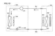
- FIG. 10 is a diagram illustrating a configuration of an air conditioner that serves as a reference for the system according to the present embodiment.
- the indoor unit 200 and the outdoor unit 300 are directly connected.
- the relay unit 100 is configured to be detachable from the air conditioner.
- the system of the present embodiment is configured by inserting the relay unit 100 between the indoor unit 200 and the outdoor unit 300 in the air conditioner as shown in FIG.
- the working fluid (first working fluid) is used between the indoor unit 200 and the outdoor unit 300 to exchange heat.
- the heat storage material (second working fluid) and the operation in a heat storage system (for example, a hot water supply unit 900 described later) that is inserted between the indoor unit 200 and the outdoor unit 300 and provided separately from the air conditioner.
- Heat exchange takes place between the fluids. That is, the relay unit 100 performs (at least) a part of the exhaust heat operation that the outdoor unit 300 should perform.
- emitted in the outdoor unit 300 is accumulate
- a refrigerant that is generally used in an empty balance machine is used.
- a refrigerant include HC (hydrocarbon) and HFC (hydrofluorocarbon).
- the heat storage material water stored in a tank 500 used in a hot water supply apparatus is cited.
- the heat storage material is not limited to water, and may be brine or the like.
- FIG. 2 is a diagram schematically showing the internal configuration of each element of the refrigeration system of FIG.
- the arrows indicate the flow direction of the working fluid that flows for heat exchange in the system of the present embodiment.
- a pipe 901 and a pipe 902 are disposed between the indoor unit 200 and the outdoor unit 300.
- the pipe 901 is a pipe for carrying the working fluid that has exchanged heat with the air in the target space from the indoor unit 200 to the outdoor unit 300.
- the pipe 902 is a pipe for sending the fluid that has exchanged heat with the air outside the target space in the outdoor unit 300 to the indoor unit 200.
- the indoor unit 200 is used for cooling the target space. From this, the working fluid sent through the pipe 901 is mainly in a gaseous state, and the working fluid flowing through the pipe 902 is mainly in a liquid state. Therefore, the pipe 901 is preferably configured to have a larger diameter than the pipe 902 in order to efficiently send the working fluid.
- the working fluid that has received heat in the heat exchange in the indoor unit 200 is sent to the outdoor unit 300 via the pipe 901. Then, in the outdoor unit 300, heat exchange for discharging the heat of the fluid is performed.
- the relay unit 100 is incorporated in a part on the pipe 902.
- the relay unit 100 includes a pipe 903 for passing the fluid.
- the relay unit 100 is connected to the air conditioner by connecting both ends of the pipe 903 to the fluid path constituted by the pipe 902.
- the diameters of both ends of the pipe 903 connected to the pipe 902 can be equal.
- a heat exchanger (condenser) 104 is provided on the pipe 903.
- the relay unit 100 is provided with a pipe 106 for a heat storage material for exchanging heat with the working fluid in the heat exchanger 104. Further, on the pipe 106, the heat storage material in the pipe 106 is shown in FIG. A pump (circulation unit) 105 that circulates in the direction of the arrow is provided.
- FIG. 2 further shows a hot water supply unit 900.
- Hot water supply unit 900 includes a tank 500.
- the heat storage material accumulated in the tank 500 is circulated by the pump 105 to be sent to the pipe 106 via the pipe 910, and then in the pipe 903 by the heat exchanger 104. It exchanges heat with the working fluid and is returned to tank 500 via piping 910.
- the heat storage material receives heat from the working fluid in the heat exchanger 104.
- the tank 500 is provided with a sensor 501 for detecting the temperature of the heat storage material in the tank 500.
- the indoor unit 200 includes a heat exchanger 201, a fan 204 for promoting heat exchange, a sensor 202 for detecting the temperature of the target space, and a filter 203 for air sent from the heat exchanger 201. It has been.
- the working fluid sent from the pipe 902 is sent to the heat exchanger 201, and the working fluid after the heat exchange is sent to the pipe 901.
- the outdoor unit 300 includes a compressor 301 that compresses the working fluid sent from the pipe 901, and a heat exchanger (condenser) 303 that exchanges heat with the air outside the target space after the compression.
- the fan 304 for promoting the heat exchange, the sensor 302 for detecting the temperature outside the target space, and the expansion valve 305 for restricting the working fluid after the heat exchange are provided.
- the outdoor unit 300 After the working fluid introduced from the pipe 901 is compressed by the compressor 301, heat exchange of air outside the target space is performed by the heat exchanger 303, and further, the working fluid is throttled by the expansion valve 305. , Sent to the pipe 902. Then, the working fluid discharged from the outdoor unit 300 is sent to the relay unit 100 via the pipe 902.
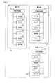
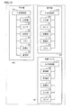
- FIG. 3 is a diagram schematically illustrating a hardware configuration of the relay unit 100, the indoor unit 200, and the outdoor unit 300 of the refrigeration system according to the present embodiment.
- relay unit 100 includes a central control unit 110 that controls the operation of the relay unit as a whole.
- the central control unit 110 includes a processor such as a CPU (Central Processing Unit).
- the relay unit 100 includes a communication unit 150 for communicating information with the indoor unit 200 and / or the outdoor unit 300.
- the communication unit 150 includes, for example, a general-purpose communication control device and a device such as a modem for controlling the communication control device.
- the relay unit 100 includes a storage unit 130 that stores programs executed by the central control unit 110 and various data.
- the storage unit 130 is configured by, for example, a hard disk.
- the central control unit 110 controls the operation of the expansion valve 103 and the pump 105.
- the central control unit 110 can also communicate with the control device of the hot water supply unit 900. For example, when the central control unit 110 receives information indicating that information instructing the hot water supply unit 900 to start hot water supply has been input, the central control unit 110 starts driving the pump 105 and instructs the stop of the hot water supply. When the information to the effect is received, the driving of the pump 105 is stopped. The central control unit 110 can acquire the detected temperature of the sensor 501 by communicating with the hot water supply unit 900 or by directly communicating with the sensor 501.
- the indoor unit 200 includes a central control unit 210 that totally controls the operation of the indoor unit.
- the central control unit 210 includes a processor such as a CPU.
- the indoor unit 200 further includes an input unit 220, a storage unit 230, and a communication unit 250.
- the input unit 220 receives input of various information such as start / stop of cooling for the air conditioner and a set temperature for the target space.
- the input unit 220 may be configured by various buttons, software keys displayed on a display device such as an LCD (Liquid Crystal Display), or a controller (remote controller) provided separately from the indoor unit 200. ) And a transmission / reception device that transmits / receives information to / from the controller.
- the storage unit 230 stores data of the program 260 executed by the central control unit 210, and is configured by a hard disk, for example.
- the communication unit 250 is a device for information communication with the relay unit 100 and / or the outdoor unit 300.
- the communication unit 250 similarly to the communication unit 150, the communication unit 250 includes a communication control device and a device such as a modem that controls the communication control device. Is done.
- the central control unit 210 receives the temperature detected by the sensor 202, receives an instruction input to the input unit 220, and controls the operations of the communication unit 250 and the fan 204.
- the outdoor unit 300 includes a central control unit 310 that controls the overall operation of the outdoor unit 300.
- the central control unit 310 includes a processor such as a CPU.
- the outdoor unit 300 includes a storage unit 330 and a communication unit 350.
- the storage unit 330 stores programs executed by the central control unit 310 and various data, and is configured by, for example, a hard disk.
- the communication unit 350 is a device for communicating information with the indoor unit 200 and / or the relay unit 100, and is configured by a device such as a communication control device and a modem that controls the communication control device, as with the communication unit 150.
- the central control unit 310 receives the temperature detected by the sensor 302. Further, the central control unit 310 controls operations of the compressor 301, the fan 304, the expansion valve 305, and the communication unit 350.
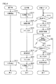
- FIG. 4 shows the central control of the indoor unit 200, the central control unit 310 of the outdoor unit 300, and the central control of the relay unit 100 when the refrigeration system of the present embodiment performs air conditioning (cooling) of the target space.
- 3 is a flowchart of processing executed in a unit 110.
- the central control unit 210 of the indoor unit 200 performs a process for starting cooling of the target space in step SA10. This process includes the start of rotation of the fan 204.
- step SA10 the central control unit 210 transmits information indicating that the above instruction has been input to the outdoor unit 300 at the start of cooling.
- the central control unit 310 of the outdoor unit 300 receives the information that the cooling start instruction has been given from the indoor unit 200, the central control unit 310 starts the compression operation of the compressor 301 in step SB10, and the fan 301 The rotation of 304 is started.
- step SA10 and step SB10 the target space is cooled.
- the central control unit 110 of the relay unit 100 detects that a hot water supply start instruction has been given in the hot water supply unit 900 during the cooling period of the target space, the central control unit 110 advances the process from step SC10 to step SC20. Then, information indicating that a hot water supply start instruction has been detected is transmitted to the outdoor unit 300.
- step SC ⁇ b> 20 central control unit 110 starts driving pump 105.
- step SB20 expansion valve 305 is opened and the process proceeds to step SB30.
- the working fluid that has been heat-exchanged by the heat exchanger 303 is sent to the pipe 902 without being throttled by the expansion valve 305.
- step SB20 the opening degree of the expansion valve 205 may not be increased to the maximum.
- the opening degree can be increased as compared with the case where adjustment is performed to throttle the working fluid when the target space is cooled. That's fine.
- the opening degree of the valve means the degree of passage of the fluid through the valve. The higher the opening degree, the larger the amount of fluid passing therethrough.
- step SB30 central control unit 310 stops the rotation of fan 304.
- step SB30 instead of stopping the rotation of the fan 304, the rotation speed of the fan 304 may be decreased as compared with that during normal cooling.
- step SB30 the degree of heat exchange of the working fluid in the heat exchanger 303 may be reduced as compared with that during normal cooling, and the rotation speed may be reduced instead of stopping the rotation of the fan 304.
- step SC20 central controller 110 reduces the opening of expansion valve 103 in step SC30, and the process proceeds to step SC40.
- the working fluid sent from the outdoor unit 300 exchanges heat with the heat storage material in the pipe 106 by the heat exchanger 104, and is then throttled by the expansion valve 103 and sent to the pipe 902.
- the central control unit 110 of the relay unit 100 determines whether or not the temperature of the heat storage material in the tank 500 has reached the set temperature of the heat storage material in the hot water supply unit 900 in step SC40. The determination is made based on central control unit 110 receiving a set temperature from hot water supply unit 900 and receiving a detection output of sensor 501.
- the central control unit 110 proceeds to step SC60 when determining that the set temperature has been reached in step SC40, and proceeds to step SC50 when determining that the set temperature has not yet been reached.
- step SC50 central control unit 110 determines whether or not an instruction to stop the hot water supply operation has been input in the hot water supply unit. If it is determined that the instruction has been input, the process proceeds to step SC60 and has not yet been input. If it is determined, the process returns to step SC40.
- central controller 110 determines in step SC40 that the temperature of the heat storage material in tank 500 has reached the set temperature, and if it determines that an instruction to stop the hot water supply operation has been input in hot water supply unit 900, Then, information notifying that is transmitted to the outdoor unit 300.
- step SC60 the central control unit 110 stops the driving of the pump 105 and advances the process to step SC70.
- step SC70 the central control unit 110 increases the opening of the expansion valve 103 and ends the process.
- step SC70 the opening degree of the expansion valve 103 is increased to the opening degree in the initial state.
- the opening degree in the initial state is, for example, an opening degree that can be sent to the pipe 902 without restricting the working fluid in the pipe 903.
- the working fluid sent from the outdoor unit 300 may be throttled even when the hot water supply operation is not performed. In this case, the opening degree of the expansion valve 103 is Even in the initial state, the working fluid can be throttled to some extent.
- step SC40 when information indicating that the heat storage material in tank 500 has reached the set temperature (YES in step SC40) is received from relay unit 100, or an instruction to stop hot water supply operation is input in hot water supply unit 900.
- the central control unit 310 closes the expansion valve 305 to the extent that the working fluid can be throttled in step SB40, and proceeds to step SB50.
- the opening degree should just be lowered
- step SB50 the central control unit 310 restarts the rotation of the fan 304.
- step SB30 when the rotational speed of the fan 304 is decreased, the rotational speed is increased so as to return to the original value.
- step SB40 As a result of the processing in step SB40, step SB50, step SC60, and step SC70 described above, the exhaust heat of the working fluid sent from the indoor unit 200 to the outdoor unit 300 is not performed in the heat exchanger 104 of the relay unit 100. This is mainly performed by the heat exchanger 303 of the outdoor unit 300.
- the central control unit 210 executes a process for stopping the cooling in step SA20. This process includes stopping the fan 204.
- step SA20 the central control unit 210 notifies the outdoor unit 300 that a cooling stop instruction has been input.
- the central control unit 310 stops the operations of the compressor 301 and the fan 304.
- the liquid heat exchange unit is configured by the relay unit 100 that is detachably connected to the air conditioner (the indoor unit 200 and the outdoor unit 300).
- the heat exchanger 104 constitutes a liquid heat exchanger.
- the liquid heat exchanger includes a first working fluid that passes through a target space heat exchanger (heat exchanger 201) and a target space heat exchanger (heat exchanger 303), a second working fluid (heat storage material), Heat exchange between the two.
- the exchanger 201 is connected sequentially.
- the relay unit 100 transmits information to that effect to the outdoor unit 300 (step SC10). Receiving the information, the outdoor unit 300 stops the rotation of the fan 304 (heat radiating fan) or reduces the rotation speed (step SB30), and increases the opening of the first expansion valve (expansion valve 305).
- the relay unit 100 only needs to be able to control the operation of the pump that circulates the heat storage material of the hot water supply unit, and the pump (the pump 105 in FIG. 2) does not necessarily have to be a component thereof.
- the pump as described above is provided as the pump 905 on the hot water supply unit 900 side, and the central control unit 110 of the relay unit 100 controls the on / off of the pump 905. Can be transmitted to the hot water supply unit 900.
- the hardware configuration shown in FIG. 3 is changed as shown in FIG.
- the relay unit 100 is not provided with the pump 105.
- Central control unit 110 transmits an instruction for turning on / off pump 905 of hot water supply unit 900 via communication unit 150.
- the operation of pump 905 is controlled in accordance with the instruction.
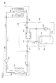
- FIG. 7 is a view showing a modification of the configuration of the refrigeration system shown in FIG.
- FIG. 8 is a diagram showing a modification of the hardware configuration shown in FIG.
- a bypass path 101 for sending the working fluid to the pipe 902 without passing through the heat exchanger 104 is provided for the pipe 903.
- An electric valve 102 for adjusting the flow rate of the working fluid in the bypass path 101 is provided on the bypass path 101. The operation of the motor operated valve 102 is controlled by the central control unit 110 of the relay unit 100.
- FIG. 9 is a modification of the flowchart of the air conditioning process shown in FIG. Referring to FIG. 9, when central control unit 110 of relay unit 100 receives a notification from hot water supply unit 900 that there is an instruction to start hot water supply in step SC10, central control unit 110 turns pump 105 on in step SC20. In addition, the outdoor unit 300 is notified that the notification to that effect has been received.
- the central control unit of the outdoor unit 300 reduces the frequency of the compressor 301 in step SB11. Thereby, the degree of compression of the working fluid introduced from the indoor unit 200 decreases.
- the central control unit 310 increases the opening of the expansion valve 305 in step SB20, and further stops the fan 304 (or decreases the rotational speed) in step SB30. .
- the central controller 110 starts driving the pump 105 in step SC20, and then closes the motor operated valve 102 in step SC21.
- the working fluid introduced from the outdoor unit 300 to the relay unit 100 is preferentially introduced into the heat exchanger 104 without passing through the bypass path 101.
- the central control unit 110 reduces the opening degree of the expansion valve 103 in step SC ⁇ b> 30 and restricts the working fluid introduced through the heat exchanger 104. As a result, the working fluid that has passed through the heat exchanger 104 is throttled by the expansion valve 103 and then introduced into the indoor unit 200.
- central controller 110 stops driving of pump 105 in step SC60, further increases the opening of motor-operated valve 102 in step SC61, and opens the opening of expansion valve 103 in step SC70. Is lowered (returned to the initial state).
- the central controller 310 reduces the opening of the expansion valve 305 to return to the initial state in step SB40, and restarts the rotation of the fan 304 (or sets the number of rotations in step SB50).
- step SB51 the frequency of the compressor 301 lowered in step SB11 is returned to the original state.
- the first working fluid passes through the predetermined valve provided on the bypass path through the bypass path by closing the motor operated valve 102 in step SC21. Corresponds to the obstructing state.
- driving of the pump 105 is started on the condition that a hot water supply instruction is given in the hot water supply unit 900.
- This pump may be driven even when no hot water supply instruction is given to hot water supply unit 900.
- the temperature of the outside air detected by the sensor 302 mounted on the outdoor unit 300 is compared with the temperature of the heat storage material detected by the sensor 501, and the operation of the pump 105 (or the pump 905) is performed according to the comparison result. May be controlled.
- the central control unit 110 drives the pump 105 to circulate the heat storage material, and further notifies the outdoor unit 300 of the comparison result.
- the central control unit 310 stops the rotation of the fan 304 or reduces the rotation speed, and further increases the opening degree of the expansion valve 305. As a result, heat exchange of the working fluid is performed mainly in the heat exchanger 104.
- the comparison of the detected temperatures may be performed by the central control unit of the outdoor unit 300, and the comparison result may be transmitted from the central control unit 310 to the central control unit 110.
- the central control unit 110 does not drive the pump 105 when the temperature detected by the sensor 501 is equal to or higher than the temperature detected by the sensor 302. Then, the central control unit 110 notifies the outdoor unit 300 of the comparison result.
- the central control unit 310 drives the fan 304 in the same way as the normal heat exchange of the working fluid so that the working fluid can be sufficiently throttled.
- the opening of 305 is adjusted.
- the central control unit 110 of the relay unit 100 transmits the detected temperature of the sensor 501 to the outdoor unit 300, for example, at regular intervals.
- the central control unit 110 transmits the set temperature of the heat storage material set in the hot water supply unit 900 to the outdoor unit 300 in advance.
- the central control unit 310 of the outdoor unit 300 compares the detected temperature (temperature of the heat storage material) of the sensor 501 received from the relay unit 100 with the set temperature, and when the difference is large (the temperature of the heat storage material is the set temperature). If it is significantly lower), the rotational speed of the compressor 301 is decreased to reduce the degree of compression of the working fluid.
- the rotational speed of the fan 304 is decreased and / or the opening degree of the expansion valve 305 is increased.
- the above processing is executed.
- the central control unit 310 can adjust the opening degree of the expansion valve 305.
- the opening degree is adjusted by the central control unit 310 changing a control amount for adjusting the opening degree of the expansion valve 305.
- the control amount is, for example, the potential of a voltage applied to adjust the opening degree of the expansion valve 305.
- a control step for changing the potential by a certain value is set, the number of steps can be used.
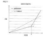
- FIG. 11 is a diagram showing the relationship between the control amount and the flow rate of the working fluid flowing through the expansion valve 305 with respect to the expansion valve 305.
- FIG. 11 shows two types of relationships. What is indicated by a broken line is the flow rate characteristic of the linear expansion valve, and what is indicated by a solid line is the flow rate characteristic of the rapid opening type expansion valve.
- the flow rate decreases at a constant rate as the control amount decreases.
- the change amount of the flow rate with respect to the change amount of the control amount is larger in the region where the control amount is larger than the Q point than in the region smaller than the Q point.
- the flow rate with respect to the control amount at the Q point is indicated by the P point in the flow rate characteristics of the rapid opening type expansion valve of FIG. 11.
- the point P corresponds to an inflection point in the flow rate characteristic of the rapid opening type expansion valve.
- the expansion valve 305 when heat exchange of the working fluid is performed by the hot water supply unit 900, the expansion valve 305 is preferably in a state in which pressure loss does not occur as much as possible.
- the expansion valve 305 when heat exchange of the working fluid by the hot water supply unit 900 is not performed, that is, when heat exchange is performed only by the outdoor unit 300, the expansion valve 305 has an opening degree to reliably atomize the working fluid. It is required that the opening degree be finely (precisely) controlled in a low region.
- the region where the flow rate is larger than the inflection point (P point) (the region where the opening degree is large and to the right of the P point in FIG. 11)
- the inclination is small. That is, the change amount of the flow rate with respect to the control amount is small.
- the expansion valve 305 When a linear expansion valve is employed as the expansion valve 305, it is difficult to precisely control the opening in a low opening area if the flow rate when fully opened is increased for heat exchange in the hot water supply unit 900. It becomes. Therefore, in the system of the present embodiment, when the heat exchange is performed in the hot water supply unit 900, the opening degree is large, and when the heat exchange is performed only in the outdoor unit 300, fine control of the opening degree is possible. Therefore, it is preferable to employ a rapid opening type expansion valve as the expansion valve 305.
- the flow rate characteristics of the rapid opening type expansion valve are not limited to a shape in which a plurality of straight lines having different inclinations are connected as shown in FIG.
- a plurality of curves having different curvatures may be connected to have an inflection point.
- a straight line and a curve may be connected and the said connection part may be used as an inflection point.
- FIG. 12 is a diagram schematically showing the configuration of the refrigeration system of the present modification.
- FIG. 13 is a diagram schematically illustrating the hardware configuration of each element of this modification.
- bypass path 101 is provided in the relay unit 100, and the flow rate of the working fluid to the bypass path 101 is further adjusted.
- a motorized valve 102 was provided.
- a modification is made such that a three-way valve 109 is provided instead of the motor-operated valve 102 with respect to the second modification.
- the three-way valve 109 is in a state in which all the working fluid sent from, for example, the outdoor unit 300 is sent to the bypass path 101 in the initial state.
- the operation of the three-way valve 109 is controlled by the central control unit 110.
- step SC21 (FIG. 9) of the second modified example, the three-way valve 109 is connected to the pipe 903 and the bypass path 101 instead of closing the motor operated valve 102.
- the three-way valve 109 is connected to the pipe 903 and the bypass path 101 instead of closing the motor operated valve 102.
- step SC61 the three-way valve 109 is controlled to send all of the working fluid to the bypass path 101 instead of increasing the opening of the motor operated valve 102.
- the pump (pump 105 or the like) was driven even when the hot water supply instruction to the hot water supply unit 900 was not given according to the relationship between the outside air temperature and the temperature of the heat storage material.
- the three-way valve 109 is controlled to be in a state of connecting the pipe 903 and the bypass path 101.
- the central control unit 110 connects the three-way valve 109 to the pipe 903 and the heat exchanger 104. Thereby, all the working fluid introduced from the outdoor unit 300 is guided to the heat exchanger 104 without passing through the bypass path 101.
- the central control unit 110 causes the three-way valve 109 to connect the pipe 903 and the bypass path 101. Thereby, the working fluid introduced from the outdoor unit 300 is all guided to the bypass path 101 without passing through the heat exchanger 104.
- the system of the embodiment and each modification described above is a system that provides cool air in the target space.
- the temperature range is not limited to the cooling system, and is a system that freezes the target space (objects such as products existing in the target space). There may be.
- Relay unit 101 Bypass path, 102 Motorized valve, 103, 205, 305 Expansion valve, 104, 201, 303 Heat exchanger, 105, 905 Pump, 106, 901, 902, 903, 910 Piping, 109 Three-way valve, 110 210, 310 Central control unit, 200 indoor units, 300 outdoor units, 301 compressor, 500 tank, 900 Hot water supply unit.
Landscapes
- Engineering & Computer Science (AREA)
- Physics & Mathematics (AREA)
- Mechanical Engineering (AREA)
- Thermal Sciences (AREA)
- General Engineering & Computer Science (AREA)
- Chemical & Material Sciences (AREA)
- Combustion & Propulsion (AREA)
- Heat-Pump Type And Storage Water Heaters (AREA)
Abstract
冷凍システムは、空気調和機の室内機(200)および室外機(300)、ならびに、中継ユニット(100)を含む。室内機(200)および室外機(300)に対して、中継ユニット(100)が、着脱可能に接続される。室外機(300)から中継ユニット(100)、作動流体が導入される。中継ユニット(100)の熱交換器(104)では、当該作動流体と、給湯ユニット(900)のタンク(500)内の水とが、熱交換する。
Description
本発明は、液体熱交換ユニットおよびそれを備える冷凍システムに関し、特に、液体熱交換器を含む液体熱交換ユニットおよびそれを備える冷凍システムに関する。
従来から、ヒートポンプは、空調等のシステムに利用されてきた。そして、このようなシステムに関し、その安定性等について、種々の技術が提案されてきた。
たとえば、特許文献1(特開2008-032376号公報)には、ヒートポンプ液体加熱エアコンにおいて、液体熱交換器を圧縮機吐出と四方弁の間に備え、かつ、加熱液体側回路にオン、オフ、或いは運転スピードが可変なポンプを配置することにより、圧縮機吐出冷媒が低温の時の液体加熱熱交換器内の加熱液体側の液体温度の低下を、ポンプ運転停止、或いはポンプ運転スピード低減で回避するための技術が開示されている。
また、特許文献2(特開2007-278582号公報)には、ヒートポンプ装置において、圧縮機と、給湯用熱交換器と空調用熱交換器との並列回路と、膨張機構と、室外熱交換器とを順次環状に接続し冷媒を循環させる冷媒サイクル装置であって、空調用熱交換器出口の冷媒と室外熱交換器出口の冷媒とを熱交換させる内部熱交換器を設け、これにより、熱交換させる冷媒の温度差が大きい状態で熱交換を行なうための技術が開示されている。
また、特許文献3(特開2005-274134号公報)には、ヒートポンプ床暖房空調装置において、圧縮機から吐出された冷媒を全て床暖房用熱交換器および室内熱交換器に流すことにより、冷媒流速を確保し伝熱性能の低下を防止するための技術が開示されている。
また、特許文献4(特開2003-172523号公報)には、ヒートポンプ床暖房空調装置において、床暖房と空調暖房の併用運転を行なうために、空調暖房+床暖房運転を実施する場合、副絞り装置によって2つの凝縮温度を作りだし、高温高圧の吐出ガス冷媒を室内熱交換器より優先して床暖房用熱交換器に流し、床暖房用熱交換器で放熱し温度の低下したガス冷媒または二相冷媒を副絞り装置によって減圧させ中圧中温の二相冷媒として下流の室内熱交換器に流す技術が開示されている。
また、特許文献5(特開2000-161811号公報)には、空気調和装置において、ピークシフト冷房運転時、及び、蓄熱(製氷)運転時に、冷媒の流路を切り替えることで給湯運転をするための技術が開示されている。
また、特許文献6(特開2006-242524号公報)には、冷房運転時に、圧縮機から吐出された冷媒が、四方弁、冷媒対水熱交換器、空冷室外熱交換器の順番に流れるように、冷媒回路に当該冷媒対水熱交換器を配置し、この冷媒対水熱交換器で冷媒と熱交換させることにより、冷房運転時には温水を、暖房運転時には冷水を取り出し可能にする技術が開示されている。
ヒートポンプは、上記したように従来から空調等において利用され、また、その環境負荷の低減効果や二酸化炭素削減効果などから、空調に限らず、給湯等の蓄熱などの幅広い範囲で利用されるようになってきている。
このような状況において、上記した従来の技術では、たとえば空調のみにおいてヒートポンプが利用されていたところに、さらにヒートポンプを蓄熱に利用しようとする場合、それらが組み合わされた新しいシステムを構築する必要があった。
したがって、上記効果を奏するヒートポンプを利用する範囲を広げようとした場合、ユーザは、既存のシステムを除去し、新しいシステムの構築を構築することを必要とされ、却って、資源や設備の無駄等を強いられる結果となっていた。
本発明は、かかる実情に鑑み考え出されたものであり、その目的は、ヒートポンプを、容易に、幅広い領域で利用できるようにすることである。
本発明に従った液体熱交換ユニットは、対象空間内熱交換器と、圧縮機と、対象空間外熱交換器と、第1の膨張弁とが順次接続されてなる冷凍サイクルに接続される液体熱交換ユニットである。液体熱交換ユニットは、対象空間内熱交換器および対象空間外熱交換器を通過する第一作動流体と第二作動流体との間で熱交換させるための液体熱交換器と、第2の膨張弁とを備える。圧縮機と、対象空間外熱交換器と、第1の膨張弁と、液体熱交換器と、第2の膨張弁と、対象空間内熱交換器とが順次接続されるように、冷凍サイクルに着脱可能に接続される。
好ましくは、液体熱交換ユニットは、対象空間外熱交換器から第2の膨張弁に、液体熱交換器を通過させることなく第一作動流体を送るためのバイパス経路と、第一作動流体をバイパス経路に通過させるか否かを制御するための所定の弁とをさらに備える。
好ましくは、液体熱交換ユニットは、第二作動流体を循環させる循環部をさらに備える。
好ましくは、液体熱交換ユニットは、所定の弁、第2の膨張弁、および、循環部の動作を、冷凍サイクルから受信した信号に応じて制御する制御部をさらに備える。
好ましくは、制御部は、第二作動流体を蓄積する蓄積部における第二作動流体の蓄積に関する情報をさらに受信し、信号と蓄積に関する情報とに応じて、所定の弁、第2の膨張弁、および、循環部の動作を制御する。
好ましくは、冷凍サイクルは、対象空間内熱交換器から対象空間外熱交換器への第一作動流体の経路を構成する第1の配管と、対象空間外熱交換器から対象空間内熱交換器への第一作動流体の経路を構成する第2の配管とを含み、液体熱交換ユニットは、第2の配管上に接続される。
好ましくは、液体熱交換ユニットは、第2の配管に接続するための、第1の接続部および第2の接続部とをさらに備える。第1の接続部の口径と第2の接続部の口径が等しい。
本発明に従った冷凍システムは、上記の液体熱交換ユニットと冷凍サイクルとを備える。
本発明によれば、ヒートポンプを利用している空気調和機や冷蔵庫などの冷凍サイクルに対して、液体熱交換ユニットが着脱可能に構成される。これにより、液体熱交換ユニットを、空気調和機や冷蔵庫のみで使用すること、或いは、液体熱交換ユニットを有する空調システムもしくは冷凍システムとしても使用することができる。
以下、本発明の冷凍サイクルについて、図面を参照して説明する。なお、以下の説明において、同一の機能および作用を有する要素については、同じ符号を付し、重複する説明を繰返さない。
<冷凍システムの概略構成>
図1は、本発明の一実施の形態である冷凍システムの概略構成を示す図である。
図1は、本発明の一実施の形態である冷凍システムの概略構成を示す図である。
図1を参照して、本システムには、空気調和機の室内機200および室外機300と、室内機200と室外機300の間に接続された中継ユニット100とを含む。本実施の形態では、中継ユニット100によって、液体熱交換ユニットの一例が構成される。また、空気調和機におけるヒートポンプサイクルにより、冷凍サイクルの一例が構成される。
図10は、本実施の形態のシステムの参考となる空気調和機の構成を示す図である。図10に示された空気調和機では、室内機200と室外機300が直接接続されている。中継ユニット100は、当該空気調和機に対して着脱可能な形態で構成される。本実施の形態のシステムは、図10に示されたような空気調和機に対して、室内機200と室外機300の間に中継ユニット100が挿入されることによって構成される。
図1に戻って、室内機200と室外機300の間では、作動流体(第一作動流体)が利用されて、熱交換が行なわれる。中継ユニット100では、室内機200と室外機300の間に挿入されて、空気調和機とは別に設けられた蓄熱システム(たとえば、後述する給湯ユニット900)における蓄熱材(第二作動流体)と作動流体の間で熱交換が行なわれる。つまり、中継ユニット100は、室外機300が行なうべき排熱動作の(少なくとも)一部を行なう。これにより、本実施の形態では、室外機300における排出される熱の(少なくとも)一部を、蓄熱材に蓄積する。
本実施の形態では、第一作動流体としては、一般的に空記調和機において利用される冷媒が利用される。このような冷媒としては、たとえば、HC(ハイドロカーボン)やHFC(ハイドロフルオロカーボン)が挙げられる。
また、蓄熱材の具体例として、給湯装置で利用されるタンク500内に貯留された水が挙げられている。なお、蓄熱材(第二作動流体)は、水に限定されず、ブライン等であっても良い。
<冷凍システムの構成>
図2は、図1の冷凍システムの各要素の内部構成を模式的に示す図である。
図2は、図1の冷凍システムの各要素の内部構成を模式的に示す図である。
図2において、矢印は、本実施の形態のシステムにおいて熱交換のために流れる作動流体の流れる方向を示している。本システムでは、室内機200と室外機300の間に、配管901と配管902が配置されている。配管901は、対象空間内の空気と熱交換した作動流体を、室内機200から室外機300へと運ぶための配管である。配管902は、室外機300において対象空間外の空気と熱交換した流体を室内機200へと送るための配管である。本実施の形態では、室内機200は、対象空間の冷房のために利用される。このことから、配管901を送られる作動流体は主に気体の状態をとり、また、配管902を流れる作動流体は主に液体の状態である。したがって、配管901は、効率よく作動流体を送るために、配管902よりも径を大きく構成されていることが好ましい。
本実施の形態のシステムでは、室内機200における熱交換において熱を受取った作動流体が、配管901を介して室外機300に送られる。そして、室外機300で、当該流体の熱を排出するための熱交換が行なわれる。本実施の形態のシステムでは、配管902上の一部に、中継ユニット100が組込まれる。
(中継ユニット100の構成)
中継ユニット100は、当該流体を通すための配管903を含む。本システムでは、配管902によって構成される流体の経路に配管903の両端が接続されることにより、中継ユニット100が空気調和機に接続される。配管903の、配管902に接続される両端の径は、等しくなり得る。
中継ユニット100は、当該流体を通すための配管903を含む。本システムでは、配管902によって構成される流体の経路に配管903の両端が接続されることにより、中継ユニット100が空気調和機に接続される。配管903の、配管902に接続される両端の径は、等しくなり得る。
中継ユニット100では、配管903上に、熱交換器(凝縮器)104が設けられている。中継ユニット100には、熱交換器104において、上記作動流体と熱交換するための蓄熱材のための配管106が設けられ、さらに、配管106上には、配管106内の蓄熱材を図2中の矢印方向に循環させるポンプ(循環部)105が設けられている。
図2では、さらに、給湯ユニット900が示されている。給湯ユニット900は、タンク500を含む。
本実施の形態のシステムでは、タンク500内に蓄積された蓄熱材が、ポンプ105によって循環されることにより、配管910を介して配管106へ送られ、そして、熱交換器104で配管903内の作動流体と熱交換し、そして、配管910を介してタンク500へと戻される。当該蓄熱材は、熱交換器104において作動流体から熱を受ける。これにより、本システムでは、作動流体が有する熱を、タンク500内の蓄熱材の加熱に利用することができる。
タンク500には、当該タンク500内の蓄熱材の温度を検知するためのセンサ501が設けられている。
(室内機200の構成)
室内機200には、熱交換器201と、熱交換を促進するためのファン204と、対象空間の温度を検知するためのセンサ202と、熱交換器201から送り出される空気に対するフィルタ203とが備えられている。
室内機200には、熱交換器201と、熱交換を促進するためのファン204と、対象空間の温度を検知するためのセンサ202と、熱交換器201から送り出される空気に対するフィルタ203とが備えられている。
熱交換器201には、配管902から送られてきた作動流体が送られ、熱交換後の作動流体は、配管901へと送られる。
(室外機300の構成)
室外機300には、配管901から送られてきた作動流体を圧縮する圧縮機301と、当該圧縮後の作動流体を対象空間外の空気と熱交換させるための熱交換器(凝縮器)303と、当該熱交換を促進するためのファン304と、対象空間外の温度を検知するためのセンサ302と、当該熱交換後の作動流体を絞るための膨張弁305が備えられている。
室外機300には、配管901から送られてきた作動流体を圧縮する圧縮機301と、当該圧縮後の作動流体を対象空間外の空気と熱交換させるための熱交換器(凝縮器)303と、当該熱交換を促進するためのファン304と、対象空間外の温度を検知するためのセンサ302と、当該熱交換後の作動流体を絞るための膨張弁305が備えられている。
室外機300では、配管901から導入された作動流体は、圧縮機301で圧縮された後、熱交換器303で対象空間外の空気の熱交換をし、さらに、膨張弁305で絞られた後、配管902へ送られる。そして、室外機300から排出された作動流体は、配管902を介して、中継ユニット100へ送られる。
<冷凍システムのハードウェア構成>
図3は、本実施の形態の冷凍システムの中継ユニット100、室内機200、および、室外機300のハードウェア構成を模式的に示す図である。
図3は、本実施の形態の冷凍システムの中継ユニット100、室内機200、および、室外機300のハードウェア構成を模式的に示す図である。
(中継ユニット100のハードウェア構成)
図3を参照して、中継ユニット100は、当該中継ユニットの動作を全体的に制御する中央制御部110を含む。中央制御部110は、CPU(Central Processing Unit)などのプロセッサを含む。
図3を参照して、中継ユニット100は、当該中継ユニットの動作を全体的に制御する中央制御部110を含む。中央制御部110は、CPU(Central Processing Unit)などのプロセッサを含む。
また、中継ユニット100は、室内機200および/または室外機300と情報通信するための通信部150を含む。通信部150は、たとえば、汎用の通信制御装置および当該通信制御装置を制御するためのモデムなどの装置によって構成される。
また、中継ユニット100は、中央制御部110が実行するプログラムや各種データを記憶する記憶部130を含む。記憶部130は、たとえば、ハードディスクによって構成される。
中継ユニット100では、中央制御部110は、膨張弁103、および、ポンプ105の動作を制御する。
中央制御部110は、給湯ユニット900の制御装置とも通信可能となっている。中央制御部110は、たとえば、当該給湯ユニット900に対して給湯の開始を指示する情報が入力された旨を示す情報を受信すると、ポンプ105の駆動を開始し、また、当該給湯の停止が指示された旨の情報を受信すると、ポンプ105の駆動を停止させる。また、中央制御部110は、給湯ユニット900と通信することにより、または、センサ501と直接通信することにより、当該センサ501の検知温度を取得できる。
(室内機200のハードウェア構成)
室内機200は、当該室内機の動作を全体的に制御する中央制御部210を含む。中央制御部210は、CPUなどのプロセッサを含む。
室内機200は、当該室内機の動作を全体的に制御する中央制御部210を含む。中央制御部210は、CPUなどのプロセッサを含む。
室内機200は、さらに、入力部220、記憶部230、および、通信部250を含む。入力部220は、空気調和機に対する冷房の開始/停止や対象空間についての設定温度などの各種情報の入力を受付ける。入力部220は、各種ボタンや、LCD(Liquid Crystal Display)などの表示装置に表示されるソフトウェアキーによって構成されてもよいし、または、室内機200に対して離間して設けられるコントローラ(リモートコントローラ)および当該コントローラと情報を送受信を行なう送受信装置によって構成されてもよい。
記憶部230は、中央制御部210が実行するプログラム260のデータを記憶し、たとえば、ハードディスクによって構成される。
通信部250は、中継ユニット100および/または室外機300と情報通信するための装置であり、たとえば、通信部150と同様に、通信制御装置および当該通信制御装置を制御するモデム等の装置によって構成される。
また、室内機200では、中央制御部210は、センサ202が検知する温度を入力され、また、入力部220に入力される指示を受付け、そして、通信部250およびファン204の動作を制御する。
(室外機300のハードウェア構成)
室外機300は、当該室外機300の動作を全体的に制御する中央制御部310を含む。中央制御部310は、CPU等のプロセッサを含む。
室外機300は、当該室外機300の動作を全体的に制御する中央制御部310を含む。中央制御部310は、CPU等のプロセッサを含む。
室外機300は、記憶部330および通信部350を含む。
記憶部330は、中央制御部310が実行するプログラムや各種のデータを記憶し、たとえば、ハードディスクによって構成される。
記憶部330は、中央制御部310が実行するプログラムや各種のデータを記憶し、たとえば、ハードディスクによって構成される。
通信部350は、室内機200および/または中継ユニット100と情報通信するための装置であり、通信部150と同様に、たとえば通信制御装置および当該通信制御装置を制御するモデム等の装置によって構成される。
また、室外機300では、中央制御部310は、センサ302が検知する温度を入力される。さらに、中央制御部310は、圧縮機301、ファン304、膨張弁305、および、通信部350の動作を制御する。
<空調処理>
図4は、本実施の形態の冷凍システムが対象空間の空調(冷房)を行なう際に、室内機200の中央制御部210、室外機300の中央制御部310、および、中継ユニット100の中央制御部110において実行される処理のフローチャートである。
図4は、本実施の形態の冷凍システムが対象空間の空調(冷房)を行なう際に、室内機200の中央制御部210、室外機300の中央制御部310、および、中継ユニット100の中央制御部110において実行される処理のフローチャートである。
以下、図4を参照して、本実施の形態における空調のための処理の内容を説明する。
室内機200の入力部220に対して、冷房の開始指示が入力されると、室内機200の中央制御部210は、ステップSA10で、対象空間の冷房を開始するための処理を行なう。当該処理は、ファン204の回転の開始を含む。
室内機200の入力部220に対して、冷房の開始指示が入力されると、室内機200の中央制御部210は、ステップSA10で、対象空間の冷房を開始するための処理を行なう。当該処理は、ファン204の回転の開始を含む。
また、中央制御部210は、ステップSA10では、冷房の開始とともに、上記指示が入力されたことを示す情報を、室外機300へ送信する。
これに応じて、室外機300の中央制御部310は、室内機200から冷房開始の指示がなされた旨の情報を受信すると、ステップSB10で、圧縮機301の圧縮動作を開始させ、また、ファン304の回転を開始させる。
ステップSA10とステップSB10により、対象空間の冷房が行なわれる。
対象空間の冷房期間中、中継ユニット100の中央制御部110が、給湯ユニット900において給湯の開始指示がなされたことを検知すると、中央制御部110は、ステップSC10から、ステップSC20へ処理を進めるとともに、給湯開始指示を検知した旨の情報を室外機300に送信する。
対象空間の冷房期間中、中継ユニット100の中央制御部110が、給湯ユニット900において給湯の開始指示がなされたことを検知すると、中央制御部110は、ステップSC10から、ステップSC20へ処理を進めるとともに、給湯開始指示を検知した旨の情報を室外機300に送信する。
ステップSC20では、中央制御部110は、ポンプ105の駆動を開始する。
一方、室外機300の中央制御部310は、中継ユニット100から上記した給湯開始指示の情報を受信すると、ステップSB20で、膨張弁305を開状態として、ステップSB30へ処理を進める。これにより、熱交換器303で熱交換された後の作動流体は、膨張弁305で絞られることなく、配管902へ送られる。なお、ステップSB20では、膨張弁205の開度が最大限上げられなくてもよい。ここでは、中継ユニット100が室内機200と室外機300の間に設けられていない状態で、対象空間の冷房が行なわれる際に作動流体を絞るために調整されるときよりも開度を上げられればよい。
一方、室外機300の中央制御部310は、中継ユニット100から上記した給湯開始指示の情報を受信すると、ステップSB20で、膨張弁305を開状態として、ステップSB30へ処理を進める。これにより、熱交換器303で熱交換された後の作動流体は、膨張弁305で絞られることなく、配管902へ送られる。なお、ステップSB20では、膨張弁205の開度が最大限上げられなくてもよい。ここでは、中継ユニット100が室内機200と室外機300の間に設けられていない状態で、対象空間の冷房が行なわれる際に作動流体を絞るために調整されるときよりも開度を上げられればよい。
本明細書において、弁の開度とは、当該弁が流体を通過させる度合いをいい、開度が高いほど通過する流体の量が多くなる。
ステップSB30では、中央制御部310は、ファン304の回転を停止させる。
なお、ステップSB30では、ファン304の回転を停止させる代わりに、ファン304の回転数を通常の冷房時よりも低下させてもよい。ステップSB30では、熱交換器303における作動流体の熱交換の度合を通常の冷房時よりも低下させられればよく、ファン304の回転を停止させる代わりに回転数を低下させてもよい。
なお、ステップSB30では、ファン304の回転を停止させる代わりに、ファン304の回転数を通常の冷房時よりも低下させてもよい。ステップSB30では、熱交換器303における作動流体の熱交換の度合を通常の冷房時よりも低下させられればよく、ファン304の回転を停止させる代わりに回転数を低下させてもよい。
一方、中継ユニット100では、ステップSC20でポンプ105の駆動を開始させた後、中央制御部110は、ステップSC30で、膨張弁103の開度を低下させて、ステップSC40へ処理が進められる。これにより、室外機300から送られてきた作動流体は、熱交換器104で配管106内の蓄熱材と熱交換を行なった後、膨張弁103で絞られて、配管902へと送られる。
そして、中継ユニット100の中央制御部110は、ステップSC40において、タンク500内の蓄熱材の温度が給湯ユニット900における蓄熱材の設定温度に達したか否かを判断する。当該判断は、中央制御部110が、給湯ユニット900から設定温度を受信し、また、センサ501の検知出力を受信することに基づいて行なわれる。
そして、中央制御部110は、ステップSC40において設定温度に達したと判断するとステップSC60へ処理を進め、まだ達していないと判断するとステップSC50へ処理を進める。
ステップSC50では、中央制御部110は、給湯ユニットにおいて、給湯動作を停止する指示が入力されたか否かを判断し、当該指示が入力されたと判断するとステップSC60へ処理を進め、まだ入力されていないと判断するとステップSC40へ処理を戻す。
なお、中央制御部110は、ステップSC40においてタンク500内の蓄熱材の温度が設定温度に達したと判断した場合、および、給湯ユニット900において給湯動作の停止指示が入力されたと判断した場合には、室外機300に対して、その旨を通知する情報を送信する。
ステップSC60では、中央制御部110は、ポンプ105の駆動を停止させて、ステップSC70へ処理を進める。ステップSC70では、中央制御部110は、膨張弁103の開度を上げて、処理を終了させる。なお、ステップSC70では、膨張弁103の開度は、初期状態の開度まで上昇される。初期状態の開度とは、たとえば、配管903内の作動流体を絞ることなく配管902へ送ることができる開度である。ただし、中継ユニット100においても、室外機300から送られてきた作動流体が、給湯動作が行なわれない状態であっても、絞られてもよく、この場合には、膨張弁103の開度は、初期状態であっても、ある程度作動流体を絞ることができるものとされる。
一方室外機300では、中継ユニット100から、タンク500内の蓄熱材が設定温度に達した旨の情報(ステップSC40でYES)を受信した場合、または、給湯ユニット900において給湯動作の停止指示が入力された旨の情報を受信した場合(ステップSC50でYES)、中央制御部310は、ステップSB40において、膨張弁305を作動流体を絞れる程度に閉じて、ステップSB50へ処理を進める。
なお、ここでは、少なくとも、ステップSB20で上げられた膨張弁305の開度が、元に(ステップSB20の状態に)戻される程度に開度が下げられればよい。
ステップSB50では、中央制御部310は、ファン304の回転を再開させる。なお、ステップSB30において、ファン304の回転数が低下された場合には、当該回転数を元に戻すように上昇させる。
以上説明したステップSB40、ステップSB50、ステップSC60、および、ステップSC70の処理により、室内機200から室外機300へ送られた作動流体の排熱が、中継ユニット100の熱交換器104では行なわれず、主に、室外機300の熱交換器303で行なわれるようになる。
そして、室内機200において、入力部220から対象空間の冷房を停止する旨の指示を入力されると、中央制御部210は、ステップSA20で冷房を停止させるための処理を実行する。当該処理は、ファン204の停止を含む。
また、ステップSA20では、中央制御部210は、冷房の停止の指示を入力されたことを、室外機300へ通知する。
室外機300では、当該通知を受けて、中央制御部310は、圧縮機301およびファン304の動作を停止させる。
以上説明した本実施の形態では、空気調和機(室内機200および室外機300)に対して着脱可能に接続される中継ユニット100により、液体熱交換ユニットが構成されている。熱交換器104により、液体熱交換器が構成される。当該液体熱交換器は、対象空間内熱交換器(熱交換器201)および対象空間外熱交換器(熱交換器303)を通過する第一作動流体と、第二作動流体(蓄熱材)との間で熱交換をさせる。
そして、本実施の形態の冷凍システムでは、室内機200と室外機300の間の作動流体の経路において、圧縮機301、熱交換器303、膨張弁305、熱交換器104、膨張弁103、熱交換器201が順次接続されている。
そして、図4を参照して説明した空調処理では、上記した給湯ユニット900において給湯動作を開始する指示(液体熱交換器の動作の開始指示)がなされた情報を入力されると、中継ユニット100の中央制御部110は、室外機300に対してその旨の情報を送信する(ステップSC10)。当該情報を受けて、室外機300は、ファン304(放熱ファン)の回転を停止または回転数を低減させ(ステップSB30)、かつ、第1の膨張弁(膨張弁305)の開度を上げる。
<第1の変形例>
以上説明した実施の形態において、中継ユニット100は、給湯ユニットの蓄熱材を循環させるポンプの動作を制御できればよく、必ずしも当該ポンプ(図2のポンプ105)をその構成要素としていなくてもよい。
以上説明した実施の形態において、中継ユニット100は、給湯ユニットの蓄熱材を循環させるポンプの動作を制御できればよく、必ずしも当該ポンプ(図2のポンプ105)をその構成要素としていなくてもよい。
つまり、図5に示されるように、上記したようなポンプは、給湯ユニット900側に、ポンプ905として備えられ、中継ユニット100の中央制御部110は、当該ポンプ905のオン/オフを制御するための情報を給湯ユニット900に対して送信できればよい。この場合、図3に示したハードウェア構成は、図6に示されるように変更される。
図6では、中継ユニット100には、ポンプ105が備えられていない。中央制御部110は、通信部150を介して、給湯ユニット900のポンプ905をオン/オフするための指示を送信する。給湯ユニット900では、当該指示に応じて、ポンプ905の動作が制御される。
<第2の変形例>
図7は、図2に示された冷凍システムの構成の変形例を示す図である。また、図8は、図3に示されたハードウェア構成の変形例を示す図である。
図7は、図2に示された冷凍システムの構成の変形例を示す図である。また、図8は、図3に示されたハードウェア構成の変形例を示す図である。
図7および図8を参照して、本変形例では、配管903に対して、熱交換器104を介さずに作動流体を配管902へ送るためのバイパス経路101が設けられている。また、バイパス経路101上には、当該バイパス経路101における作動流体の流量を調整するための電動弁102が設けられている。電動弁102の動作は、中継ユニット100の中央制御部110によって制御される。
本変形例では、室内機200から室外機300へ送られた作動流体の放熱が中継ユニット100の熱交換器104において行なわれる際には、圧縮機301の動作が調整され、また、バイパス経路101における作動流体の流量も調整される。
図9は、図4に示された空調処理のフローチャートの変形例である。
図9を参照して、ステップSC10で中継ユニット100の中央制御部110が給湯ユニット900から給湯開始の指示があった旨の通知を受けると、中央制御部110は、ポンプ105をステップSC20でオンさせるとともに、その旨の通知を受けたことを、室外機300へ通知する。
図9を参照して、ステップSC10で中継ユニット100の中央制御部110が給湯ユニット900から給湯開始の指示があった旨の通知を受けると、中央制御部110は、ポンプ105をステップSC20でオンさせるとともに、その旨の通知を受けたことを、室外機300へ通知する。
当該通知を受けて、室外機300の中央制御部は、ステップSB11で、圧縮機301の周波数を低下させる。これにより、室内機200から導入された作動流体の圧縮の度合が低下する。
そして、中央制御部310は、図4を参照して説明したように、ステップSB20で膨張弁305の開度を上げ、さらに、ステップSB30で、ファン304を停止(または、回転数を低下)させる。
一方、中継ユニット100では、中央制御部110は、ステップSC20でポンプ105の駆動を開始した後、ステップSC21で、電動弁102を閉じさせる。これにより、室外機300から中継ユニット100へ導入された作動流体が、バイパス経路101を通ることなく、優先的に、熱交換器104に導入される。
そして、中央制御部110は、図4を参照して説明したように、ステップSC30で膨張弁103の開度を低下させて、熱交換器104を経て導入される作動流体を絞る。これにより、熱交換器104を経た作動流体が、膨張弁103によって絞られた後、室内機200へ導入される。
また、本変形例では、タンク500内の蓄熱材が設定温度に達するか(ステップSC40でYES)、または、給湯ユニット900に対して給湯動作を停止する指示が入力されたことが検知されると(ステップSC50でYES)、中央制御部110は、ステップSC60でポンプ105の駆動を停止させ、さらに、ステップSC61で電動弁102の開度を上げて、そして、ステップSC70で膨張弁103の開度を低下(初期状態に戻す)させる。
一方、室外機300では、中央制御部310は、ステップSB40で膨張弁305の開度を初期状態に戻すように低下させ、ステップSB50で、ファン304の回転を再開させ(または、回転数をステップSB30で低下させる前のものに戻し)、さらに、ステップSB51で、ステップSB11で低下させた圧縮機301の周波数を元に戻す。
以上説明した本変形例の空調処理では、ステップSC21で電動弁102が閉状態とされることにより、バイパス経路上に設けられた所定の弁を第一作動流体が当該バイパス経路に通過することを妨げる状態に相当する。
<第3の変形例>
以上説明した本実施の形態および各変形例では、給湯ユニット900において給湯指示がなされたことを条件として、ポンプ105(または、ポンプ905)の駆動が開始された。なお、このポンプは、給湯ユニット900に対する給湯指示がなされていない状態であっても、駆動されてもよい。たとえば、室外機300に搭載されたセンサ302が検知する外気の温度と、センサ501が検知する蓄熱材の温度を比較し、当該比較の結果に応じて、ポンプ105(または、ポンプ905)の動作が制御されてもよい。
以上説明した本実施の形態および各変形例では、給湯ユニット900において給湯指示がなされたことを条件として、ポンプ105(または、ポンプ905)の駆動が開始された。なお、このポンプは、給湯ユニット900に対する給湯指示がなされていない状態であっても、駆動されてもよい。たとえば、室外機300に搭載されたセンサ302が検知する外気の温度と、センサ501が検知する蓄熱材の温度を比較し、当該比較の結果に応じて、ポンプ105(または、ポンプ905)の動作が制御されてもよい。
具体的には、蓄熱材の温度が外気温の温度よりも低いときには、作動流体は、熱交換器303において外気と熱交換するよりも、熱交換器104において蓄熱材と熱交換する方が、効率よく熱を放出できると考えられる。したがって、中央制御部110は、センサ501の検知温度がセンサ302の検知温度よりも低いときには、ポンプ105を駆動させることにより蓄熱材を循環させ、さらに、当該比較結果を室外機300へ通知する。室外機300では、当該比較結果を受信すると、中央制御部310は、ファン304の回転を停止または回転数を低下させ、さらに、膨張弁305の開度を上げる。これにより、作動流体の熱交換が、主に熱交換器104で行なわれるようになる。
なお、このような検知温度の比較は、室外機300の中央制御部が実行し、当該比較結果が、中央制御部310から中央制御部110へ送信されてもよい。
一方、中央制御部110は、センサ501の検知温度がセンサ302の検知温度以上であるときには、このようなポンプ105の駆動は行なわない。そして、中央制御部110は、室外機300に対して、当該比較結果を通知する。
室外機300では、当該比較結果の通知を受けて、中央制御部310は、通常の作動流体の熱交換と同様に、ファン304を駆動させ、作動流体を十分に絞ることができるように膨張弁305の開度を調整する。
<第4の変形例>
本実施の形態の冷凍システムでは、室外機300では、冷房動作中の給湯ユニット900における給湯が行なわれる際には、蓄熱材の温度とその設定温度との差に応じて圧縮機301の動作が制御されてもよい。
本実施の形態の冷凍システムでは、室外機300では、冷房動作中の給湯ユニット900における給湯が行なわれる際には、蓄熱材の温度とその設定温度との差に応じて圧縮機301の動作が制御されてもよい。
この場合、中継ユニット100の中央制御部110は、たとえば、一定時間毎に、センサ501の検知温度を室外機300へ送信する。また、中央制御部110は、室外機300に、予め、給湯ユニット900において設定されている蓄熱材の設定温度を室外機300へ送信している。
室外機300の中央制御部310は、中継ユニット100から受信したセンサ501の検知温度(蓄熱材の温度)とその設定温度とを比較し、当該差が大きい場合(蓄熱材の温度がその設定温度より著しく低い場合)には、作動流体の圧縮の度合を低くするべく圧縮機301の回転数を低下させる。
また、室外機300では、さらに、蓄熱材の温度がその設定温度に対して著しく低い場合には、ファン304の回転数を低下させたり、および/または、膨張弁305の開度を上げたりすることにより、室外機300における作動流体の熱交換の度合を低くするために、上記処理を実行する。
<第5の変形例>
以上説明した実施の形態およびその変形例では、中央制御部310は、膨張弁305の開度を調整できる。本明細書では、中央制御部310が膨張弁305の開度を調整するための制御量を変化させることにより、当該開度が調整される。制御量とは、たとえば、膨張弁305の開度を調整するために印加される電圧の電位である。一定値ずつ電位を変化させる制御ステップが設定されている場合には、ステップ数とすることもできる。
以上説明した実施の形態およびその変形例では、中央制御部310は、膨張弁305の開度を調整できる。本明細書では、中央制御部310が膨張弁305の開度を調整するための制御量を変化させることにより、当該開度が調整される。制御量とは、たとえば、膨張弁305の開度を調整するために印加される電圧の電位である。一定値ずつ電位を変化させる制御ステップが設定されている場合には、ステップ数とすることもできる。
図11は、膨張弁305に関する、上記の制御量と膨張弁305を介して流れる作動流体の流量の関係を示す図である。図11には、2種類の関係が示されている。破線で記載されているのはリニア型膨張弁の流量特性であり、実線で記載されているのは急開型膨張弁の流量特性である。
図11のリニア型膨張弁の流量特性では、制御量の低下に従って、一定の割合で流量が小さくなっている。一方、図11の急開型膨張弁の流量特性では、制御量がQ点より大きい領域では、Q点より小さい領域と比較して、制御量の変化量に対する流量の変化量が大きい。なお、図11では、図11の急開型膨張弁の流量特性において、Q点の制御量に対する流量がP点で示されている。P点は、急開型膨張弁の流量特性において変曲点に相当する。
本実施の形態において給湯ユニット900による作動流体の熱交換が行なわれる際には、膨張弁305は、可能な限り圧力損失を生じない状態とされることが好ましい。一方、給湯ユニット900による作動流体の熱交換が行なわれない場合、つまり、室外機300のみで熱交換が行なわれる場合には、確実に作動流体を霧化するため、膨張弁305は、開度の低い領域でその開度が細かく(精密に)制御されることを必要とされる。
ここで、図11の急開型膨張弁の流量特性において、変曲点(P点)より流量が多い領域(開度が大きい領域であって、図11中のP点より右側)よりも、流量が少ない領域(開度が小さい領域であって、図11中のP点より左側)の方が、傾きが小さい。つまり、制御量に対する流量の変化量が小さい。
膨張弁305としてリニア型膨張弁が採用された場合、給湯ユニット900で熱交換が行なわれるときのために全開時の流量を大きくすると、開度の低い領域での開度の精密な制御が困難となる。したがって、本実施の形態のシステムでは、給湯ユニット900で熱交換が行なわれる際には開度が大きく、かつ、室外機300でのみ熱交換が行なわれる際には開度の木目細かい制御が可能となるように、膨張弁305として、急開型膨張弁が採用されることが好ましい。
なお、急開型膨張弁の流量特性は、図11に示されたような傾きの異なる複数の直線が連結されたような形状に限定されない。曲率の異なる複数の曲線が連結されて、変曲点を有するものであっても良い。または、直線と曲線が連結されて、当該連結部を変曲点とするものであっても良い。
<第6の変形例>
図12は、本変形例の冷凍システムの構成を模式的に示す図である。また、図13は、本変形例の各要素のハードウェア構成を模式的に示す図である。
図12は、本変形例の冷凍システムの構成を模式的に示す図である。また、図13は、本変形例の各要素のハードウェア構成を模式的に示す図である。
上記の第2の変形例では、図7および図9を参照して説明されたように、中継ユニット100においてバイパス経路101が設けられ、さらに、当該バイパス経路101への作動流体の流量を調整する電動弁102が設けられた。
本変形例では、図12に示されるように、第2の変形例に対し、電動弁102の代わりに三方弁109を設けるという変更が加えられている。本変形例では、三方弁109は、初期状態では、たとえば室外機300から送られてきた作動流体をすべてバイパス経路101に送る状態とされている。三方弁109の動作は、中央制御部110によって制御される。
本変形例の空調処理として、第2の変形例において図9を参照して説明された処理が、適宜変更を加えられて、実行される。
つまり、第2の変形例のステップSC21(図9)において、電動弁102が閉じられる代わりに、三方弁109が配管903とバイパス経路101を接続する状態とされる。これにより、中継ユニット100において熱交換が行なわれる際には、中継ユニット100に送られてきた作動流体のすべてが、バイパス経路101を通らず、熱交換器104を通る。これにより、より効率よく、作動流体が運んできた熱を蓄熱材に伝えることができる。
本変形例では、ステップSC61において、電動弁102の開度が上げられる代わりに、三方弁109が、作動流体のすべてをバイパス経路101に送る状態へと制御される。
また、第3の変形例では、ポンプ(ポンプ105等)が、外気温度と蓄熱材の温度の関係に応じて、給湯ユニット900に対する給湯指示がなされていない状態であっても駆動された。本変形例では、このようにポンプが駆動されるとき、三方弁109は、配管903とバイパス経路101を接続する状態となるよう制御される。
つまり、蓄熱材の温度(センサ501の検知温度)が外気温度(センサ302)よりも低いときには、中央制御部110は、三方弁109に、配管903と熱交換器104とを接続させる。これにより、室外機300から導入された作動流体は、バイパス経路101を通ることなく、すべて熱交換器104に導かれる。
一方、蓄熱材の温度が外気温度以上である場合には、中央制御部110は、三方弁109に、配管903とバイパス経路101とを接続させる。これにより、室外機300から導入された作動流体は、熱交換器104を通ることなく、すべてバイパス経路101に導かれる。
<その他の変形例等>
以上説明した本実施の形態では、既存の空気調和機に対して中継ユニットを接続することにより、改めて中継ユニットを含むような空気調和システムを導入することなく、空気調和機における廃熱を有効利用することができる。
以上説明した本実施の形態では、既存の空気調和機に対して中継ユニットを接続することにより、改めて中継ユニットを含むような空気調和システムを導入することなく、空気調和機における廃熱を有効利用することができる。
以上説明した実施の形態および各変形例のシステムは、対象空間の冷風を提供するシステムとされている。なお、本発明に従ったシステムは、対象空間を冷却するものであれば、その温度範囲は、冷房システムに限らず、対象空間(に存在する商品等の対象物)を冷凍させるようなシステムであっても良い。
今回開示された各実施の形態はすべての点で例示であって制限的なものではないと考えられるべきである。本発明の範囲は上記した説明ではなくて請求の範囲によって示され、請求の範囲と均等の意味および範囲内でのすべての変更が含まれることが意図される。また、実施の形態およびその変形例に記載の発明は、単独で、または、可能な限り組合わされて、実施されることが意図される。
100 中継ユニット、101 バイパス経路、102 電動弁、103,205,305 膨張弁、104,201,303 熱交換器、105,905 ポンプ、106,901,902,903,910 配管、109 三方弁、110,210,310 中央制御部、200 室内機、300 室外機、301 圧縮機、500 タンク、900
給湯ユニット。
給湯ユニット。
Claims (8)
- 対象空間内熱交換器(201)と、圧縮機(301)と、対象空間外熱交換器(303)と、第1の膨張弁(305)とが順次接続されてなる冷凍サイクルに接続される液体熱交換ユニット(100)であって、
前記対象空間内熱交換器(201)および前記対象空間外熱交換器(303)を通過する第一作動流体と第二作動流体との間で熱交換させるための液体熱交換器(104)と、
第2の膨張弁(103)とを備え、
前記圧縮機(301)と、前記対象空間外熱交換器(303)と、前記第1の膨張弁(305)と、前記液体熱交換器(104)と、前記第2の膨張弁(103)と、前記対象空間内熱交換器(201)とが順次接続されるように、前記冷凍サイクルに着脱可能に接続される、液体熱交換ユニット(100)。 - 前記対象空間外熱交換器(303)から前記第2の膨張弁(103)に、前記液体熱交換器(104)を通過させることなく前記第一作動流体を送るためのバイパス経路(101)と、
前記第一作動流体を前記バイパス経路(101)に通過させるか否かを制御するための所定の弁とをさらに備える、請求項1に記載の液体熱交換ユニット(100)。 - 前記第二作動流体を循環させる循環部(105)をさらに備える、請求項2に記載の液体熱交換ユニット(100)。
- 前記所定の弁、前記第2の膨張弁(103)、および、前記循環部(105)の動作を、前記冷凍サイクルから受信した信号に応じて制御する制御部(110)をさらに備える、請求項3に記載の液体熱交換ユニット(100)。
- 前記制御部(110)は、
前記第二作動流体を蓄積する蓄積部における前記第二作動流体の蓄積に関する情報をさらに受信し、
前記信号と前記蓄積に関する情報とに応じて、前記所定の弁、前記第2の膨張弁(103)、および、前記循環部(105)の動作を制御する、請求項4に記載の液体熱交換ユニット(100)。 - 前記冷凍サイクルは、前記対象空間内熱交換器(201)から前記対象空間外熱交換器(303)への前記第一作動流体の経路を構成する第1の配管(901)と、前記対象空間外熱交換器(303)から前記対象空間内熱交換器(201)への前記第一作動流体の経路を構成する第2の配管(902)とを含み、
前記第2の配管(902)上に接続される、請求項1~請求項5のいずれかに記載の液体熱交換ユニット(100)。 - 前記第2の配管(902)に接続するための、第1の接続部および第2の接続部とをさらに備え、
前記第1の接続部の口径と前記第2の接続部の口径が等しい、請求項6に記載の液体熱交換ユニット(100)。 - 請求項1に記載の液体熱交換ユニット(100)と前記冷凍サイクルとを備える、冷凍システム。
Applications Claiming Priority (2)
| Application Number | Priority Date | Filing Date | Title |
|---|---|---|---|
| JP2011-161064 | 2011-07-22 | ||
| JP2011161064A JP5242745B2 (ja) | 2011-07-22 | 2011-07-22 | 冷凍システム |
Publications (1)
| Publication Number | Publication Date |
|---|---|
| WO2013015126A1 true WO2013015126A1 (ja) | 2013-01-31 |
Family
ID=47600978
Family Applications (1)
| Application Number | Title | Priority Date | Filing Date |
|---|---|---|---|
| PCT/JP2012/067810 Ceased WO2013015126A1 (ja) | 2011-07-22 | 2012-07-12 | 液体熱交換ユニットおよびそれを備える冷凍システム |
Country Status (2)
| Country | Link |
|---|---|
| JP (1) | JP5242745B2 (ja) |
| WO (1) | WO2013015126A1 (ja) |
Families Citing this family (1)
| Publication number | Priority date | Publication date | Assignee | Title |
|---|---|---|---|---|
| ES2934137T3 (es) * | 2016-09-23 | 2023-02-17 | Daikin Ind Ltd | Sistema de aire acondicionado y suministro de agua caliente |
Citations (7)
| Publication number | Priority date | Publication date | Assignee | Title |
|---|---|---|---|---|
| JPS62218769A (ja) * | 1986-03-19 | 1987-09-26 | シャープ株式会社 | ヒ−トポンプ暖房給湯装置 |
| JPH01277181A (ja) * | 1988-04-28 | 1989-11-07 | M T Akua:Kk | 冷房給湯装置,暖房給湯装置及び冷暖給湯装置 |
| JPH05280818A (ja) * | 1992-04-01 | 1993-10-29 | Matsushita Refrig Co Ltd | 多室冷暖房装置 |
| JP2002130862A (ja) * | 2000-10-26 | 2002-05-09 | Yutaka Ukiyuuden | 空気調和システム |
| JP2003343936A (ja) * | 2002-05-28 | 2003-12-03 | Mitsubishi Electric Corp | 冷凍サイクル装置 |
| JP2008032376A (ja) * | 2006-07-06 | 2008-02-14 | Tsutomu Kuroda | ヒートポンプ液体加熱エアコン、或いは機器 |
| JP2011064401A (ja) * | 2009-09-17 | 2011-03-31 | Yutaka Ukuta | 空気調和機による給湯システム |
-
2011
- 2011-07-22 JP JP2011161064A patent/JP5242745B2/ja active Active
-
2012
- 2012-07-12 WO PCT/JP2012/067810 patent/WO2013015126A1/ja not_active Ceased
Patent Citations (7)
| Publication number | Priority date | Publication date | Assignee | Title |
|---|---|---|---|---|
| JPS62218769A (ja) * | 1986-03-19 | 1987-09-26 | シャープ株式会社 | ヒ−トポンプ暖房給湯装置 |
| JPH01277181A (ja) * | 1988-04-28 | 1989-11-07 | M T Akua:Kk | 冷房給湯装置,暖房給湯装置及び冷暖給湯装置 |
| JPH05280818A (ja) * | 1992-04-01 | 1993-10-29 | Matsushita Refrig Co Ltd | 多室冷暖房装置 |
| JP2002130862A (ja) * | 2000-10-26 | 2002-05-09 | Yutaka Ukiyuuden | 空気調和システム |
| JP2003343936A (ja) * | 2002-05-28 | 2003-12-03 | Mitsubishi Electric Corp | 冷凍サイクル装置 |
| JP2008032376A (ja) * | 2006-07-06 | 2008-02-14 | Tsutomu Kuroda | ヒートポンプ液体加熱エアコン、或いは機器 |
| JP2011064401A (ja) * | 2009-09-17 | 2011-03-31 | Yutaka Ukuta | 空気調和機による給湯システム |
Also Published As
| Publication number | Publication date |
|---|---|
| JP2013024497A (ja) | 2013-02-04 |
| JP5242745B2 (ja) | 2013-07-24 |
Similar Documents
| Publication | Publication Date | Title |
|---|---|---|
| JP5242746B2 (ja) | 液体熱交換ユニットおよび冷凍システム | |
| CN102422092B (zh) | 空气调节装置 | |
| JP6190388B2 (ja) | ヒートポンプ温水暖房機 | |
| JP6269756B1 (ja) | 冷凍装置 | |
| JP5929450B2 (ja) | 冷凍サイクル装置 | |
| CN103119377B (zh) | 制冷热水供给装置以及制冷热水供给方法 | |
| EP2362164A2 (en) | Heat pump system and control method thereof | |
| JP5631012B2 (ja) | 空気調和機および空気調和機の制御方法 | |
| JP6177811B2 (ja) | 車両用ヒートポンプの除霜に使用する自動制御方法 | |
| JP6976878B2 (ja) | ヒートポンプ空調システム | |
| JP2012141113A (ja) | 空気調和温水機器システム | |
| JP2013119954A (ja) | ヒートポンプ式温水暖房機 | |
| WO2019093249A1 (ja) | 冷媒サイクル装置 | |
| JP5737353B2 (ja) | 空気調和装置 | |
| JP6085207B2 (ja) | ヒートポンプ装置 | |
| CN110741208A (zh) | 空调装置 | |
| JP6231403B2 (ja) | 複合熱源ヒートポンプ装置 | |
| JP6537990B2 (ja) | ヒートポンプ式冷温水供給システム | |
| JP2017067318A (ja) | 空気調和装置 | |
| CN105115210A (zh) | 风冷热泵冷热水机组及其化霜控制方法 | |
| CN105241141B (zh) | 风冷热泵冷热水机组及其化霜控制方法 | |
| JP5242745B2 (ja) | 冷凍システム | |
| WO2017050072A1 (zh) | 风冷热泵冷热水机组及其化霜控制方法 | |
| JP5517891B2 (ja) | 空気調和装置 | |
| JP5516332B2 (ja) | ヒートポンプ式温水暖房機 |
Legal Events
| Date | Code | Title | Description |
|---|---|---|---|
| 121 | Ep: the epo has been informed by wipo that ep was designated in this application |
Ref document number: 12817596 Country of ref document: EP Kind code of ref document: A1 |
|
| NENP | Non-entry into the national phase |
Ref country code: DE |
|
| 122 | Ep: pct application non-entry in european phase |
Ref document number: 12817596 Country of ref document: EP Kind code of ref document: A1 |