WO2013014865A1 - Vehicle approach warning device - Google Patents
Vehicle approach warning device Download PDFInfo
- Publication number
- WO2013014865A1 WO2013014865A1 PCT/JP2012/004314 JP2012004314W WO2013014865A1 WO 2013014865 A1 WO2013014865 A1 WO 2013014865A1 JP 2012004314 W JP2012004314 W JP 2012004314W WO 2013014865 A1 WO2013014865 A1 WO 2013014865A1
- Authority
- WO
- WIPO (PCT)
- Prior art keywords
- voltage
- output
- abnormality
- sound
- approach notification
- Prior art date
Links
Images


Classifications
-
- B—PERFORMING OPERATIONS; TRANSPORTING
- B60—VEHICLES IN GENERAL
- B60Q—ARRANGEMENT OF SIGNALLING OR LIGHTING DEVICES, THE MOUNTING OR SUPPORTING THEREOF OR CIRCUITS THEREFOR, FOR VEHICLES IN GENERAL
- B60Q5/00—Arrangement or adaptation of acoustic signal devices
- B60Q5/005—Arrangement or adaptation of acoustic signal devices automatically actuated
- B60Q5/008—Arrangement or adaptation of acoustic signal devices automatically actuated for signaling silent vehicles, e.g. for warning that a hybrid or electric vehicle is approaching
-
- B—PERFORMING OPERATIONS; TRANSPORTING
- B06—GENERATING OR TRANSMITTING MECHANICAL VIBRATIONS IN GENERAL
- B06B—METHODS OR APPARATUS FOR GENERATING OR TRANSMITTING MECHANICAL VIBRATIONS OF INFRASONIC, SONIC, OR ULTRASONIC FREQUENCY, e.g. FOR PERFORMING MECHANICAL WORK IN GENERAL
- B06B1/00—Methods or apparatus for generating mechanical vibrations of infrasonic, sonic, or ultrasonic frequency
- B06B1/02—Methods or apparatus for generating mechanical vibrations of infrasonic, sonic, or ultrasonic frequency making use of electrical energy
- B06B1/0207—Driving circuits
-
- B—PERFORMING OPERATIONS; TRANSPORTING
- B60—VEHICLES IN GENERAL
- B60L—PROPULSION OF ELECTRICALLY-PROPELLED VEHICLES; SUPPLYING ELECTRIC POWER FOR AUXILIARY EQUIPMENT OF ELECTRICALLY-PROPELLED VEHICLES; ELECTRODYNAMIC BRAKE SYSTEMS FOR VEHICLES IN GENERAL; MAGNETIC SUSPENSION OR LEVITATION FOR VEHICLES; MONITORING OPERATING VARIABLES OF ELECTRICALLY-PROPELLED VEHICLES; ELECTRIC SAFETY DEVICES FOR ELECTRICALLY-PROPELLED VEHICLES
- B60L3/00—Electric devices on electrically-propelled vehicles for safety purposes; Monitoring operating variables, e.g. speed, deceleration or energy consumption
- B60L3/0007—Measures or means for preventing or attenuating collisions
- B60L3/0015—Prevention of collisions
-
- B—PERFORMING OPERATIONS; TRANSPORTING
- B60—VEHICLES IN GENERAL
- B60L—PROPULSION OF ELECTRICALLY-PROPELLED VEHICLES; SUPPLYING ELECTRIC POWER FOR AUXILIARY EQUIPMENT OF ELECTRICALLY-PROPELLED VEHICLES; ELECTRODYNAMIC BRAKE SYSTEMS FOR VEHICLES IN GENERAL; MAGNETIC SUSPENSION OR LEVITATION FOR VEHICLES; MONITORING OPERATING VARIABLES OF ELECTRICALLY-PROPELLED VEHICLES; ELECTRIC SAFETY DEVICES FOR ELECTRICALLY-PROPELLED VEHICLES
- B60L3/00—Electric devices on electrically-propelled vehicles for safety purposes; Monitoring operating variables, e.g. speed, deceleration or energy consumption
- B60L3/0023—Detecting, eliminating, remedying or compensating for drive train abnormalities, e.g. failures within the drive train
- B60L3/0046—Detecting, eliminating, remedying or compensating for drive train abnormalities, e.g. failures within the drive train relating to electric energy storage systems, e.g. batteries or capacitors
-
- B—PERFORMING OPERATIONS; TRANSPORTING
- B60—VEHICLES IN GENERAL
- B60L—PROPULSION OF ELECTRICALLY-PROPELLED VEHICLES; SUPPLYING ELECTRIC POWER FOR AUXILIARY EQUIPMENT OF ELECTRICALLY-PROPELLED VEHICLES; ELECTRODYNAMIC BRAKE SYSTEMS FOR VEHICLES IN GENERAL; MAGNETIC SUSPENSION OR LEVITATION FOR VEHICLES; MONITORING OPERATING VARIABLES OF ELECTRICALLY-PROPELLED VEHICLES; ELECTRIC SAFETY DEVICES FOR ELECTRICALLY-PROPELLED VEHICLES
- B60L3/00—Electric devices on electrically-propelled vehicles for safety purposes; Monitoring operating variables, e.g. speed, deceleration or energy consumption
- B60L3/0023—Detecting, eliminating, remedying or compensating for drive train abnormalities, e.g. failures within the drive train
- B60L3/0069—Detecting, eliminating, remedying or compensating for drive train abnormalities, e.g. failures within the drive train relating to the isolation, e.g. ground fault or leak current
-
- B—PERFORMING OPERATIONS; TRANSPORTING
- B60—VEHICLES IN GENERAL
- B60L—PROPULSION OF ELECTRICALLY-PROPELLED VEHICLES; SUPPLYING ELECTRIC POWER FOR AUXILIARY EQUIPMENT OF ELECTRICALLY-PROPELLED VEHICLES; ELECTRODYNAMIC BRAKE SYSTEMS FOR VEHICLES IN GENERAL; MAGNETIC SUSPENSION OR LEVITATION FOR VEHICLES; MONITORING OPERATING VARIABLES OF ELECTRICALLY-PROPELLED VEHICLES; ELECTRIC SAFETY DEVICES FOR ELECTRICALLY-PROPELLED VEHICLES
- B60L3/00—Electric devices on electrically-propelled vehicles for safety purposes; Monitoring operating variables, e.g. speed, deceleration or energy consumption
- B60L3/04—Cutting off the power supply under fault conditions
-
- B—PERFORMING OPERATIONS; TRANSPORTING
- B60—VEHICLES IN GENERAL
- B60L—PROPULSION OF ELECTRICALLY-PROPELLED VEHICLES; SUPPLYING ELECTRIC POWER FOR AUXILIARY EQUIPMENT OF ELECTRICALLY-PROPELLED VEHICLES; ELECTRODYNAMIC BRAKE SYSTEMS FOR VEHICLES IN GENERAL; MAGNETIC SUSPENSION OR LEVITATION FOR VEHICLES; MONITORING OPERATING VARIABLES OF ELECTRICALLY-PROPELLED VEHICLES; ELECTRIC SAFETY DEVICES FOR ELECTRICALLY-PROPELLED VEHICLES
- B60L3/00—Electric devices on electrically-propelled vehicles for safety purposes; Monitoring operating variables, e.g. speed, deceleration or energy consumption
- B60L3/12—Recording operating variables ; Monitoring of operating variables
-
- B—PERFORMING OPERATIONS; TRANSPORTING
- B60—VEHICLES IN GENERAL
- B60L—PROPULSION OF ELECTRICALLY-PROPELLED VEHICLES; SUPPLYING ELECTRIC POWER FOR AUXILIARY EQUIPMENT OF ELECTRICALLY-PROPELLED VEHICLES; ELECTRODYNAMIC BRAKE SYSTEMS FOR VEHICLES IN GENERAL; MAGNETIC SUSPENSION OR LEVITATION FOR VEHICLES; MONITORING OPERATING VARIABLES OF ELECTRICALLY-PROPELLED VEHICLES; ELECTRIC SAFETY DEVICES FOR ELECTRICALLY-PROPELLED VEHICLES
- B60L58/00—Methods or circuit arrangements for monitoring or controlling batteries or fuel cells, specially adapted for electric vehicles
- B60L58/10—Methods or circuit arrangements for monitoring or controlling batteries or fuel cells, specially adapted for electric vehicles for monitoring or controlling batteries
- B60L58/12—Methods or circuit arrangements for monitoring or controlling batteries or fuel cells, specially adapted for electric vehicles for monitoring or controlling batteries responding to state of charge [SoC]
- B60L58/14—Preventing excessive discharging
-
- B—PERFORMING OPERATIONS; TRANSPORTING
- B60—VEHICLES IN GENERAL
- B60L—PROPULSION OF ELECTRICALLY-PROPELLED VEHICLES; SUPPLYING ELECTRIC POWER FOR AUXILIARY EQUIPMENT OF ELECTRICALLY-PROPELLED VEHICLES; ELECTRODYNAMIC BRAKE SYSTEMS FOR VEHICLES IN GENERAL; MAGNETIC SUSPENSION OR LEVITATION FOR VEHICLES; MONITORING OPERATING VARIABLES OF ELECTRICALLY-PROPELLED VEHICLES; ELECTRIC SAFETY DEVICES FOR ELECTRICALLY-PROPELLED VEHICLES
- B60L58/00—Methods or circuit arrangements for monitoring or controlling batteries or fuel cells, specially adapted for electric vehicles
- B60L58/10—Methods or circuit arrangements for monitoring or controlling batteries or fuel cells, specially adapted for electric vehicles for monitoring or controlling batteries
- B60L58/12—Methods or circuit arrangements for monitoring or controlling batteries or fuel cells, specially adapted for electric vehicles for monitoring or controlling batteries responding to state of charge [SoC]
- B60L58/15—Preventing overcharging
-
- H—ELECTRICITY
- H04—ELECTRIC COMMUNICATION TECHNIQUE
- H04R—LOUDSPEAKERS, MICROPHONES, GRAMOPHONE PICK-UPS OR LIKE ACOUSTIC ELECTROMECHANICAL TRANSDUCERS; DEAF-AID SETS; PUBLIC ADDRESS SYSTEMS
- H04R29/00—Monitoring arrangements; Testing arrangements
- H04R29/001—Monitoring arrangements; Testing arrangements for loudspeakers
-
- B—PERFORMING OPERATIONS; TRANSPORTING
- B06—GENERATING OR TRANSMITTING MECHANICAL VIBRATIONS IN GENERAL
- B06B—METHODS OR APPARATUS FOR GENERATING OR TRANSMITTING MECHANICAL VIBRATIONS OF INFRASONIC, SONIC, OR ULTRASONIC FREQUENCY, e.g. FOR PERFORMING MECHANICAL WORK IN GENERAL
- B06B2201/00—Indexing scheme associated with B06B1/0207 for details covered by B06B1/0207 but not provided for in any of its subgroups
- B06B2201/40—Indexing scheme associated with B06B1/0207 for details covered by B06B1/0207 but not provided for in any of its subgroups with testing, calibrating, safety devices, built-in protection, construction details
-
- B—PERFORMING OPERATIONS; TRANSPORTING
- B06—GENERATING OR TRANSMITTING MECHANICAL VIBRATIONS IN GENERAL
- B06B—METHODS OR APPARATUS FOR GENERATING OR TRANSMITTING MECHANICAL VIBRATIONS OF INFRASONIC, SONIC, OR ULTRASONIC FREQUENCY, e.g. FOR PERFORMING MECHANICAL WORK IN GENERAL
- B06B2201/00—Indexing scheme associated with B06B1/0207 for details covered by B06B1/0207 but not provided for in any of its subgroups
- B06B2201/70—Specific application
-
- B—PERFORMING OPERATIONS; TRANSPORTING
- B60—VEHICLES IN GENERAL
- B60L—PROPULSION OF ELECTRICALLY-PROPELLED VEHICLES; SUPPLYING ELECTRIC POWER FOR AUXILIARY EQUIPMENT OF ELECTRICALLY-PROPELLED VEHICLES; ELECTRODYNAMIC BRAKE SYSTEMS FOR VEHICLES IN GENERAL; MAGNETIC SUSPENSION OR LEVITATION FOR VEHICLES; MONITORING OPERATING VARIABLES OF ELECTRICALLY-PROPELLED VEHICLES; ELECTRIC SAFETY DEVICES FOR ELECTRICALLY-PROPELLED VEHICLES
- B60L2240/00—Control parameters of input or output; Target parameters
- B60L2240/10—Vehicle control parameters
- B60L2240/12—Speed
-
- B—PERFORMING OPERATIONS; TRANSPORTING
- B60—VEHICLES IN GENERAL
- B60L—PROPULSION OF ELECTRICALLY-PROPELLED VEHICLES; SUPPLYING ELECTRIC POWER FOR AUXILIARY EQUIPMENT OF ELECTRICALLY-PROPELLED VEHICLES; ELECTRODYNAMIC BRAKE SYSTEMS FOR VEHICLES IN GENERAL; MAGNETIC SUSPENSION OR LEVITATION FOR VEHICLES; MONITORING OPERATING VARIABLES OF ELECTRICALLY-PROPELLED VEHICLES; ELECTRIC SAFETY DEVICES FOR ELECTRICALLY-PROPELLED VEHICLES
- B60L2250/00—Driver interactions
- B60L2250/10—Driver interactions by alarm
-
- B—PERFORMING OPERATIONS; TRANSPORTING
- B60—VEHICLES IN GENERAL
- B60L—PROPULSION OF ELECTRICALLY-PROPELLED VEHICLES; SUPPLYING ELECTRIC POWER FOR AUXILIARY EQUIPMENT OF ELECTRICALLY-PROPELLED VEHICLES; ELECTRODYNAMIC BRAKE SYSTEMS FOR VEHICLES IN GENERAL; MAGNETIC SUSPENSION OR LEVITATION FOR VEHICLES; MONITORING OPERATING VARIABLES OF ELECTRICALLY-PROPELLED VEHICLES; ELECTRIC SAFETY DEVICES FOR ELECTRICALLY-PROPELLED VEHICLES
- B60L2250/00—Driver interactions
- B60L2250/22—Driver interactions by presence detection
-
- B—PERFORMING OPERATIONS; TRANSPORTING
- B60—VEHICLES IN GENERAL
- B60L—PROPULSION OF ELECTRICALLY-PROPELLED VEHICLES; SUPPLYING ELECTRIC POWER FOR AUXILIARY EQUIPMENT OF ELECTRICALLY-PROPELLED VEHICLES; ELECTRODYNAMIC BRAKE SYSTEMS FOR VEHICLES IN GENERAL; MAGNETIC SUSPENSION OR LEVITATION FOR VEHICLES; MONITORING OPERATING VARIABLES OF ELECTRICALLY-PROPELLED VEHICLES; ELECTRIC SAFETY DEVICES FOR ELECTRICALLY-PROPELLED VEHICLES
- B60L2250/00—Driver interactions
- B60L2250/26—Driver interactions by pedal actuation
-
- B—PERFORMING OPERATIONS; TRANSPORTING
- B60—VEHICLES IN GENERAL
- B60L—PROPULSION OF ELECTRICALLY-PROPELLED VEHICLES; SUPPLYING ELECTRIC POWER FOR AUXILIARY EQUIPMENT OF ELECTRICALLY-PROPELLED VEHICLES; ELECTRODYNAMIC BRAKE SYSTEMS FOR VEHICLES IN GENERAL; MAGNETIC SUSPENSION OR LEVITATION FOR VEHICLES; MONITORING OPERATING VARIABLES OF ELECTRICALLY-PROPELLED VEHICLES; ELECTRIC SAFETY DEVICES FOR ELECTRICALLY-PROPELLED VEHICLES
- B60L2270/00—Problem solutions or means not otherwise provided for
- B60L2270/42—Means to improve acoustic vehicle detection by humans
-
- H—ELECTRICITY
- H04—ELECTRIC COMMUNICATION TECHNIQUE
- H04R—LOUDSPEAKERS, MICROPHONES, GRAMOPHONE PICK-UPS OR LIKE ACOUSTIC ELECTROMECHANICAL TRANSDUCERS; DEAF-AID SETS; PUBLIC ADDRESS SYSTEMS
- H04R2420/00—Details of connection covered by H04R, not provided for in its groups
- H04R2420/05—Detection of connection of loudspeakers or headphones to amplifiers
-
- H—ELECTRICITY
- H04—ELECTRIC COMMUNICATION TECHNIQUE
- H04R—LOUDSPEAKERS, MICROPHONES, GRAMOPHONE PICK-UPS OR LIKE ACOUSTIC ELECTROMECHANICAL TRANSDUCERS; DEAF-AID SETS; PUBLIC ADDRESS SYSTEMS
- H04R2499/00—Aspects covered by H04R or H04S not otherwise provided for in their subgroups
- H04R2499/10—General applications
- H04R2499/13—Acoustic transducers and sound field adaptation in vehicles
-
- Y—GENERAL TAGGING OF NEW TECHNOLOGICAL DEVELOPMENTS; GENERAL TAGGING OF CROSS-SECTIONAL TECHNOLOGIES SPANNING OVER SEVERAL SECTIONS OF THE IPC; TECHNICAL SUBJECTS COVERED BY FORMER USPC CROSS-REFERENCE ART COLLECTIONS [XRACs] AND DIGESTS
- Y02—TECHNOLOGIES OR APPLICATIONS FOR MITIGATION OR ADAPTATION AGAINST CLIMATE CHANGE
- Y02T—CLIMATE CHANGE MITIGATION TECHNOLOGIES RELATED TO TRANSPORTATION
- Y02T10/00—Road transport of goods or passengers
- Y02T10/60—Other road transportation technologies with climate change mitigation effect
- Y02T10/70—Energy storage systems for electromobility, e.g. batteries
Definitions
- the present disclosure relates to a vehicle approach notification device that notifies the surroundings that a vehicle is approaching by generating sound from the vehicle.
- EV vehicles electric vehicles
- HV vehicles hybrid vehicles
- the generated noise is structurally small, and it is difficult for pedestrians to notice the approach of these vehicles.
- EV approach vehicles and HV vehicles have a vehicle approach notification device that generates vehicle approach notification sounds such as a pseudo engine sound and a pseudo motor sound in order to raise awareness that a vehicle is nearby in the vicinity of a pedestrian or the like. Is being mounted (see, for example, Patent Document 1).
- the inventor of the present application has found the following regarding the vehicle approach notification device.
- the vehicle approach notification device as described above, if any abnormality occurs in the speaker and the sound cannot be generated, the function of reporting the approach of the vehicle from the vehicle to the pedestrian is lost. If the driver keeps driving without knowing it, the driver actually travels on the premise that the vehicle approach notification sound is pronounced to the pedestrian, but in fact the vehicle approach notification sound Is not pronounced, and there is a problem that it is difficult for the pedestrian to notice the approach of the vehicle. For this reason, it is necessary to be able to detect the abnormality of the vehicle approach notification device.
- a method for detecting an abnormality of such a vehicle approach notification device a method of using a current (hereinafter referred to as a speaker current) flowing through a speaker during sound generation or a voltage applied (hereinafter referred to as a speaker voltage) can be considered.
- a speaker current a current flowing through a speaker during sound generation or a voltage applied
- a speaker voltage a voltage applied
- the speaker current and the speaker voltage at the time of sound generation always vary. Therefore, in an extreme event where the speaker current does not flow through the speaker output wiring when the speaker is open (disconnected), and an excessive direct current flows through the speaker output wiring when the speaker is short-circuited, the current sensor circuit or voltage sensor circuit generates a sound. Can be detected by monitoring the sensor current or sensor voltage at and comparing with the threshold value for determining whether the speaker is open or short.
- a vehicle approach notification device that reports the approach of the vehicle by generating a vehicle approach notification sound from a sounding body (3) mounted on the vehicle
- An approach notification sound waveform generator (21a) for generating a sound output corresponding to an approach notification sound waveform for generating a vehicle approach notification sound for sound generation from the sound generator (3)
- a power amplifier (22) for generating an input voltage (VIN) according to the sound output
- a high-pass filter (24) that inputs the input voltage (VIN), outputs an output voltage (VOUT) obtained by filtering a low-frequency component of the input voltage (VIN), and applies the output voltage (VOUT) to the sounding body (3)
- a voltage sensor circuit (25) having an integration circuit for integrating the output voltage (VOUT), and outputting an integration circuit voltage obtained by integrating the output voltage (VOUT) by the integration circuit
- An abnormality monitor unit (21b) that monitors an integration circuit voltage output from the voltage sensor circuit (25) and detects an abnormality of the sounding body (3) based on the integration circuit voltage
- the sound output passes through the power amplifier (22) and the high-pass filter (24), so that the output voltage (VOUT) corresponding to the sound output is applied to the sound generator (3) to generate the vehicle approach sound.
- the vehicle approach notification device includes a voltage sensor circuit (25) that monitors the output voltage (VOUT), and generates a check output as a sound output when an abnormality is detected. Then, abnormality detection is performed based on whether the integration circuit voltage output from the voltage sensor circuit (25) is within or outside the voltage range that is the threshold value for abnormality determination. Thereby, abnormality detection can be reliably performed in all the abnormality modes.
- FIG. 1 is a block diagram of a vehicle approach notification system including a vehicle approach notification device according to the first embodiment.
- FIG. 2 is a circuit block diagram showing a specific configuration example of the voltage sensor circuit 25 provided in the vehicle approach notification device 2.
- FIGS. 3A to 3F are diagrams showing the relationship between the input frequency and the change in impedance of the speaker 3 in each abnormal mode and in the normal state.
- 4 (a) to 4 (f) are diagrams showing the relationship between the frequency of the sound output and the change in the frequency characteristics of the HPF 24 in each abnormal mode and in the normal state.
- FIGS. 7A to 7F are diagrams showing the relationship between the frequency of the sound output and the change in the frequency characteristics of the HPF 24 in each abnormal mode and in the normal state.
- FIG. 8A to FIG. 8F are diagrams showing each abnormal mode and each voltage waveform in the normal state.
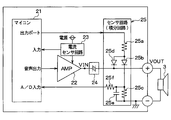
- FIG. 1 is a block diagram of a vehicle approach notification system including a vehicle approach notification device according to the present embodiment. With reference to this figure, the vehicle approach notification system including the vehicle approach notification apparatus according to the present embodiment will be described.
- the vehicle approach notification system includes a vehicle speed sensor 1, a vehicle approach notification device 2, a speaker 3, and an alarm device 4.
- the vehicle approach notification device 2 generates a sound from the speaker 3 that is a sounding body, thereby reporting the approach of the vehicle to surrounding pedestrians and the like.
- the vehicle approach notification device 2 is separated from the speaker 3, but the speaker 3 may be integrated with the vehicle approach notification device 2.
- the vehicle speed sensor 1 outputs a vehicle speed detection signal as a signal indicating the running state of the vehicle.
- the vehicle approach notification device 2 When the detection signal of the vehicle speed sensor 1 is input to the vehicle approach notification device 2, the vehicle approach notification device 2 generates a vehicle approach notification sound corresponding to the vehicle speed.
- the vehicle approach notification device 2 includes a microcomputer 21, a power amplifier (hereinafter referred to as AMP) 22, a current sensor circuit 23, a high-pass filter (hereinafter referred to as HPF) 24, and a voltage sensor circuit 25.
- AMP power amplifier
- HPF high-pass filter
- the microcomputer 21 includes an approach notification sound waveform generation unit 21a, an abnormality monitor unit 21b, a storage device 21c, and the like.
- the approach notification sound generation unit 21a has a memory (not shown) and a digital analog converter (hereinafter referred to as DAC) or a PWM output device.
- the memory stores sound control programs and PCM (Pulse Code Modulation) data, that is, audio data converted into data codes and encoded, and corresponds to the vehicle speed indicated by the vehicle speed detection signal An arithmetic expression or a map of the attached sound pressure level is stored.
- PCM Pulse Code Modulation
- the approach notification sound generation unit 21a calculates a sound pressure level corresponding to the vehicle speed using an arithmetic expression or a map,
- the sound pressure level corresponding to the approach notification sound waveform is generated by setting the sound pressure level calculated from the PCM data to a DAC or PWM output device at a predetermined sampling period and outputting it. For example, by increasing the sound pressure level as the vehicle speed increases, the degree of recognition of the approach of the vehicle to a pedestrian or the like is improved.
- the abnormality monitor unit 21b detects whether the speaker 3 is normal or malfunctioned based on the output of the voltage sensor circuit 25, that is, detects abnormality.
- the abnormal mode includes open (disconnected) of the speaker 3, an intermediate open that is about to be opened, a short, an intermediate short that is about to be shorted, and icing and fixing of the speaker 3. Any of these abnormal modes can be detected as an abnormal state by the abnormality monitor unit 21b.
- the abnormality monitor unit 21b calculates an average value of the voltage output from the voltage sensor circuit 25, and determines whether or not the average value is included in a voltage range stored in advance as a threshold value for abnormality determination. Anomaly detection is performed based on this.
- the voltage range used as a threshold for abnormality determination is a constant value, and as described later, the voltage range used as the threshold for abnormality determination is set to a constant value by using a sound output with a constant frequency called a check output. I can do it. Details of the abnormality detection by the abnormality monitoring unit 21b will be described later.
- the storage device 21c stores specific failure mode information as failure history information when it is detected that the speaker 3 has failed due to failure detection by the failure monitoring unit 21b.
- the contents stored in the storage device 21c in this way are used for failure diagnosis at a repair shop such as an automobile dealer, so that serviceability and maintenance performance can be improved.
- the AMP 22 applies a voltage corresponding to the output of the microcomputer 21 to the speaker 3 based on the power supply from the power source.
- a voltage input from the AMP 22 to the speaker 3 is referred to as an input voltage VIN.
- the current sensor circuit 23 detects the magnitude of the current supplied from the power source to the AMP 22.
- the current sensor circuit 23 detects that the current supplied to the AMP 22 is an overcurrent.
- the detection result of the current sensor circuit 23 is input to the microcomputer 21.
- the microcomputer 21 stops the current supply to the AMP 22, for example, so that the speaker 3 A measure such as temporarily stopping the voltage application to is performed. Thereby, it is prevented that the vehicle approach notification device 2 breaks down due to overcurrent, or that the sound generation is not performed with a sound pressure that is not assumed by the speaker 3.
- the HPF 24 filters the low-frequency component of the input voltage VIN from the AMP 22 and passes only the high-frequency band, and is constituted by a coupling capacitor, for example.
- the voltage sensor circuit 25 monitors the voltage applied to the speaker 3 through the HPF 24.
- the voltage sensor circuit 25 is configured by an integration circuit, and inputs an integrated value of the voltage applied to the speaker 3 to the microcomputer 21 as an output of the voltage sensor circuit 25.
- the voltage applied to the speaker 3 monitored by the voltage sensor circuit 25 corresponds to the voltage output from the vehicle approach notification device 2. In the following description, this voltage is referred to as output voltage VOUT.
- FIG. 2 is a circuit block diagram showing a specific configuration example of the voltage sensor circuit 25 provided in the vehicle approach notification device 2 having such a configuration.
- the configuration of the microcomputer 21 is the same as that shown in FIG.
- the audio output of the microcomputer 21a is input to the AMP 22, and the AMP 22 outputs the input voltage VIN to the speaker 3 based on the current supply from the power source.
- the input voltage VIN is filtered by the HPF 24 including a coupling capacitor and the like, and then applied to the speaker 3 as the output voltage VOUT of the vehicle approach notification device 2, so that the sound pressure corresponding to the sound output from the speaker 3 is obtained. And a vehicle approach notification sound of frequency is generated.
- the voltage sensor circuit 25 is connected to a speaker output wiring to which the output voltage VOUT is transmitted, integrates the output voltage VOUT by an integration circuit, and inputs the integration value to the microcomputer 21.
- the voltage sensor circuit 25 includes a charging current limiting resistor 25a, a first diode 25b, a discharging resistor 25c, a second diode 25d, a capacitor 25e, and an input limiting resistor 25f. ing.
- the charging current limiting resistor 25a, the first diode 25b, and the discharging resistor 25c are connected in series between the output port of the microcomputer 21 and GND.
- the second diode 25d is provided between the connection point between the charging current limiting resistor 25a and the first diode 25b and the speaker output wiring to which the output voltage VOUT is transmitted.
- the capacitor 25e is connected in parallel to the discharge resistor 25c.
- the input limiting resistor 25 f is connected between the connection point between the first diode 25 b and the discharge resistor 25 c and the microcomputer 21.
- the cathode potential of the first diode 25b is substantially equal to the cathode potential of the second diode 25d.
- the output voltage VOUT appears as a cathode potential of the first diode 25b in a half-wave rectified form, and the cathode potential is the first potential.
- the cathode potential can be made in a state where there is no influence of the voltage drop of Vf of the second diodes 25b and 25d.
- the voltage sensor circuit 25 is pulled up with reference to the potential of the output port of the microcomputer 21. Based on the potential difference between the potential of the output port and the cathode potential of the first diode 25b, a current flows through the path of the charging current limiting resistor 25a, the first diode 25b, and the discharge resistor 25c, and the current is interrupted.
- the capacitor 25e is charged / discharged according to the potential difference between the voltages at both ends of 25c. Since charging is performed via the charging current limiting resistor 25a during charging, the charging current is prevented from becoming excessive. Further, at the time of discharging, the A / D input voltage of the microcomputer 21 is gradually lowered by setting the resistance value of the discharge resistor 25c to a large value so that the output voltage VOUT can be peak-held. .
- the voltage corresponding to the integral value of the output voltage VOUT can be input to the microcomputer 21 by inputting the charging voltage of the capacitor 25e to the microcomputer 21 via the input limiting resistor 25f.
- the approach notification sound generation unit 21a when the vehicle speed detection signal from the vehicle speed sensor 1 is input to the microcomputer 21, the approach notification sound generation unit 21a generates a sound output according to the vehicle speed indicated by the vehicle speed detection signal. generate.
- the approach notification sound generation unit 21a calculates the sound pressure level according to the vehicle speed using an arithmetic expression or a map according to the control program stored in the memory, and sets the sound pressure level calculated from the PCM data. Is output to a DAC or a PWM output device or the like at predetermined sampling periods to generate a sound output corresponding to the approach notification sound waveform.
- An input voltage VIN corresponding to the sound output from the approach notification sound generation unit 21a is output via the AMP 22, and after the input voltage VIN is filtered by the HPF 24, the output voltage VOUT of the vehicle approach notification device 2 is output.
- the speaker 3 Applied to the speaker 3. Thereby, the speaker 3 generates a vehicle approach notification sound corresponding to the vehicle speed and notifies the pedestrian or the like of the approach of the vehicle.
- a check output is generated from the approach notification sound generator 21a as a sound output.
- the check output is a frequency included in the speaker resonance frequency band, and is, for example, a low frequency (for example, 60 Hz or less) single frequency output that is difficult for the user to recognize and has a low reproduction capability.
- a low frequency with a low reproduction capability of the speaker 3 it is possible to suppress sound from the speaker 3 when an abnormality is detected, and to avoid making the driver uncomfortable.
- Such abnormality detection can be performed at any time as long as the vehicle approach notification sound is not generated, so that it can always be performed when the vehicle approach notification sound is not generated, and the frequency of abnormality detection can be increased. It becomes possible.
- the input voltage VIN corresponding to this check output is output via the AMP 22, and after this input voltage VIN is filtered by the HPF 24, it is applied to the speaker 3 as the output voltage VOUT of the vehicle approach notification device 2.
- the vehicle approach notification sound may be output from the speaker 3, but since the low frequency single frequency check output that is difficult for the user to recognize and has low reproduction capability is used, almost no sound is generated. Can be.
- the output voltage VOUT at this time is detected by the voltage sensor circuit 25 and the integrated value thereof is input to the abnormality monitor unit 21b of the microcomputer 21, and based on this, the abnormality monitor unit 21b detects abnormality of the speaker 3 by a method described later. .
- the abnormality monitor unit 21b notifies the storage unit 21c that the failure of the speaker 3 has been detected, thereby storing the failure history information, and the warning device 4 notifies the fact. Is output to the driver via the warning device 4 that the speaker 3 has failed.
- the warning device 4 is constituted by a warning light in a meter or a display in an instrument panel, etc., and is constituted by something that can be visually recognized by a driver or that emits a notification sound. Via such an alarm device 4, it is possible to notify the driver that the speaker 3 is out of order and that the notification function is temporarily or permanently disabled. It is possible to avoid the belief that pedestrians should notice because they are pronounced.
- a voltage sensor configured by an integration circuit with a voltage range when the speaker 3 is normal as a threshold for abnormality determination Even if an abnormality is detected depending on whether the output of the circuit 25 exceeds the voltage range, the abnormality cannot be detected accurately. This will be described with reference to FIGS.
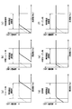
- 3 (a) to 3 (f) are diagrams showing the relationship between the frequency of the sound output (input frequency) and the change in impedance of the speaker 3 in each abnormal mode and in the normal state.
- 4A to 4F are diagrams showing the relationship between the frequency of the sound output and the change in the frequency characteristics of the HPF 24 in each abnormal mode and in the normal state.
- 5 (a) to 5 (f) show the voltage applied to the speaker 3 (output voltage VOUT) in each abnormal mode and in the normal state, and the output voltage (hereinafter referred to as voltage sensor circuit 25) composed of an integrating circuit.
- FIG. 4 is a diagram showing a voltage obtained by averaging an integration circuit voltage for determination with a threshold (hereinafter referred to as an average voltage) and a voltage range used as a threshold for abnormality determination.
- the broken lines shown in FIG. 3 and FIG. 4 are the characteristics at the normal time.
- the impedance of the speaker 3 changes according to the abnormal mode.
- the change in the impedance of the speaker 3 may not necessarily be greater than that in the normal mode.
- the vehicle approach notification sound has a range of frequency components, and it cannot be understood at which input frequency the abnormality detection is performed.
- the frequency characteristics of the HPF 24 also vary depending on the input frequency, but the frequency components of the vehicle approach notification sound vary.
- the integration circuit voltage varies depending on the attenuation at the HPF 24, that is, the output voltage VOUT / the input voltage VIN, the attenuation at the HPF 24 becomes 0 when the input frequency increases to some extent, and the integration circuit voltage is normal and abnormal. Therefore, it is difficult to discriminate between the normal time and the abnormal time by the integration circuit voltage.
- the output voltage VOUT applied to the speaker 3 becomes 0 and the integration circuit voltage and the average voltage become 0 when short-circuited. Further, at the time of opening, the output voltage VOUT becomes a value sufficiently larger than that at the normal time, and the integration circuit voltage and the average voltage become values sufficiently larger than those at the normal time. In these cases, the average voltage becomes a value greatly deviating from the voltage range used as a threshold for abnormality determination, so that abnormality detection can be reliably performed.
- the output voltage VOUT does not become 0 or a sufficiently large value as compared with the normal time when the intermediate is short-circuited, frozen, or intermediately opened. For this reason, the integration circuit voltage and the average voltage are not significantly different from those in the normal state, and the average voltage is within or close to the voltage range used as a threshold for abnormality determination, so that reliable abnormality detection is possible. It becomes impossible to do.
- abnormality detection is performed using the output for checking.
- the check output is set to the sound output of the frequency included in the speaker resonance frequency band. This check output is output when a vehicle approach notification sound such as a pseudo engine sound or a pseudo motor sound is not generated, and an abnormality is detected when the check output is generated.
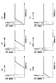
- FIGS. 8A to 8F are diagrams showing the output voltage VOUT, the integration circuit voltage, the average voltage, and the voltage range used as an abnormality determination threshold value in each abnormal mode and in a normal state. is there.
- the broken lines shown in FIG. 6 and FIG. 7 are the characteristics during normal operation.
- the impedance of the speaker 3 increases compared to other frequency bands due to the resonance phenomenon.
- This region is the speaker resonance frequency band, and the frequency of the speaker output is, for example, in the vicinity of the resonance frequency f0 in which the impedance of the speaker 3 takes a maximum value in the resonance frequency band and is smaller than the resonance frequency f0. Is set.
- the output voltage VOUT applied to the speaker 3 becomes 0, the integration circuit voltage and the average voltage become 0, and the average voltage is abnormal. It becomes a value smaller than the voltage range used as the threshold for determination.
- the output voltage VOUT is attenuated more than normal, the integration circuit voltage and the average voltage are smaller than normal, and the average voltage becomes a value smaller than the voltage range used as a threshold for abnormality determination.
- the output voltage VOUT is attenuated more than normal, although the attenuation is smaller than that in the middle short, the integration circuit voltage and average voltage are also smaller than normal, and the average voltage becomes the threshold value for abnormality determination.
- the value is smaller than the voltage range to be applied.
- the output voltage VOUT is not attenuated more than normal, the integration circuit voltage and the average voltage are larger than normal, and the average voltage is larger than the voltage range used as a threshold for abnormality determination.
- the pull-up of the voltage sensor circuit 25 is dominant and the output voltage VOUT becomes a sufficiently larger value than normal, and the integrating circuit voltage and the average voltage are sufficiently larger than normal.
- the average voltage is larger than the voltage range used as the abnormality determination threshold value.
- the frequency of the output for check preferably by setting the frequency of the speaker 3 in the resonance frequency band to a frequency smaller than the resonance frequency f0 at which the impedance is a maximum value, In this way, it is possible to reliably detect abnormality.
- abnormality detection in addition to the fact that abnormality detection has been performed, whether the average voltage is smaller or larger than the voltage range used as a threshold for abnormality determination
- the history information is stored in the storage device 21c.
- the stored contents stored in the storage device 21c as the failure history information can be utilized for failure diagnosis at a repair shop such as an automobile dealer, thereby improving serviceability and maintainability.
- the resonance frequency of the speaker 3 is determined by the size, shape, etc. of the speaker 3, and the sound of the approach notification sound generator 21a in the microcomputer 21 is generated so that the output voltage VOUT in the resonance frequency band of the speaker 3 is generated.
- the output and the filter constant of the HPF 24 are set.
- the vehicle approach notification device 2 that causes the sound output from the microcomputer 21 to pass through the AMP 22 and the HPF 24 so that the output voltage VOUT corresponding to the sound output is applied to the speaker 3 to generate the vehicle approach sound.
- a voltage sensor circuit 25 for monitoring the output voltage VOUT is provided, and a check output is generated as a sound output when an abnormality is detected. Then, abnormality detection is performed based on whether the integration circuit voltage output from the voltage sensor circuit 25 is within or outside the voltage range that is the threshold value for abnormality determination. Thereby, abnormality detection can be reliably performed in all the abnormality modes.
- the current supplied to the AMP 22 by the current sensor circuit 23 is detected as an overcurrent, and the current supply to the AMP 22 is stopped as an example of a measure when the current is overcurrent.
- the detection result of the current sensor circuit 23 can be used in accordance with the detection result of the voltage sensor circuit 24. That is, if an overcurrent is detected by the current sensor circuit 23, the application of voltage to the speaker 3 may be stopped if an abnormality is detected based on the integration circuit voltage output from the voltage sensor circuit 25. good.
- the vehicle speed sensor was used as what shows the driving state of a vehicle
- a vehicle approach notification sound is changed. You can also.
- the sound pressure level or frequency of the vehicle approach notification sound may be changed according to the accelerator pedal opening based on a detection signal from a sensor that detects the accelerator pedal opening (or engine speed).
- a vehicle approach notification device having various aspects can be provided.
- a vehicle approach notification device that reports the approach of the vehicle by generating a vehicle approach notification sound from a sound generator (3) mounted on the vehicle generates a vehicle approach notification sound that generates a sound from the sound generator (3).
- An approach notification sound waveform generator (21a) that generates a sound output corresponding to the approach notification sound waveform for generation, a power amplifier (22) that generates an input voltage (VIN) corresponding to the sound output, and an input voltage ( VIN), an output voltage (VOUT) obtained by filtering the low frequency component of the input voltage (VIN) is output and applied to the sounding body (3), and the output voltage (VOUT) is integrated.
- an approach notification sound generator (21a) that provides an alarm to that effect via an alarm (4)
- the approach notification sound waveform generator (21a) A sound generation output having a frequency lower than the resonance frequency in the resonance frequency band is generated, and the abnormality monitor unit (21b) generates a power amplifier (22) and a high-pass filter (24) based on the sound output that becomes a check output when abnormality is detected.
- the output voltage (VOUT) is applied to the sounding body (3) via)
- an integration circuit voltage obtained by integrating the output voltage (VOUT) by the integration circuit of the voltage sensor circuit (25) is input and stored in advance. do it Configured to detect an abnormality of the sounding body (3) by comparing with have abnormality determination threshold value.
- the sound output passes through the power amplifier (22) and the high-pass filter (24), so that the output voltage (VOUT) corresponding to the sound output is applied to the sound generator (3) to generate the vehicle approach sound.
- the vehicle approach notification device includes a voltage sensor circuit (25) that monitors the output voltage (VOUT), and generates a check output as a sound output when an abnormality is detected. Then, abnormality detection is performed based on whether the integration circuit voltage output from the voltage sensor circuit (25) is within or outside the voltage range that is the threshold value for abnormality determination. Thereby, abnormality detection can be reliably performed in all the abnormality modes.
- the abnormality monitor unit (21b) calculates an average value of the integration circuit voltage when an abnormality is detected, and whether or not the average value is within a voltage range that is used as a threshold value for abnormality determination. Therefore, the sound generator (3) may be detected for abnormality.
- the vehicle approach notification device has a current sensor circuit (23) that detects a current supplied from a power source to the power amplifier (22), and supplies the power amplifier (22) with the current sensor circuit (23). If the detected current is detected to be an overcurrent, the current supply from the power source to the power amplifier (22) is stopped, and the application of the output voltage (VOUT) to the sound generator (3) is stopped. You may do it.
- the vehicle approach notification device When the current sensor circuit (23) detects that the current supplied to the power amplifier (22) is an overcurrent, the vehicle approach notification device has a voltage sensor circuit (21b) If an abnormality is detected based on the integration circuit voltage output by 25), the application of the output voltage (VOUT) to the sound generator (3) may be stopped.
- the vehicle approach notification device may include a storage device (21c) that stores as a failure history information when the abnormality monitor unit (21b) detects that the sounding body (3) is abnormal.
- failure history information By storing the failure history information in the storage device (21c) in this way, it is possible to utilize the stored contents for failure diagnosis at a repair shop such as an automobile dealer, and to improve serviceability and maintainability. It becomes.
Abstract
Provided is a vehicle approach warning device which performs abnormality detection in various abnormal modes. A vehicle approach warning device emits a vehicle approach sound by causing a sound output from a microcomputer (21) to pass through an AMP (22) and an HPF (24) and applying output voltage (VOUT) corresponding to the sound output to a loudspeaker (3). The vehicle approach warning device is provided with a voltage sensor circuit (25) for monitoring the output voltage (VOUT), and produces an output for checking, as the sound output, when detecting an abnormality. As the output for checking, a frequency within a speaker resonant frequency band, for example, a single-frequency output that is difficult to recognize by a user and has low frequency at which the reproduction capability of the speaker is low is used. The abnormality detection is performed on the basis of whether or not an integration circuit voltage outputted by the voltage sensor circuit (25) falls within a voltage range defined as a threshold for abnormality detection.
Description
本出願は、2011年7月27日に出願された日本特許出願2011-164502号に基づくものであり、ここにその記載内容を参照により援用する。
This application is based on Japanese Patent Application No. 2011-164502 filed on July 27, 2011, the contents of which are incorporated herein by reference.
本開示は、車両から音声を発生させることにより、車両が接近していることを周囲に通報する車両接近通報装置に関するものである。
The present disclosure relates to a vehicle approach notification device that notifies the surroundings that a vehicle is approaching by generating sound from the vehicle.
電気自動車(EV車)やハイブリッド車(HV車)などでは、その構造的に発生騒音が小さく、これらの車両の接近を歩行者が気付き難い。このことから近年、EV車やHV車には、歩行者など周囲に車両が近くにいるという認知度を上げるために擬似エンジン音や擬似モータ音などの車両接近通報音を発生させる車両接近通報装置が搭載されつつある(例えば、特許文献1参照)。
In electric vehicles (EV vehicles) and hybrid vehicles (HV vehicles), the generated noise is structurally small, and it is difficult for pedestrians to notice the approach of these vehicles. For this reason, in recent years, EV approach vehicles and HV vehicles have a vehicle approach notification device that generates vehicle approach notification sounds such as a pseudo engine sound and a pseudo motor sound in order to raise awareness that a vehicle is nearby in the vicinity of a pedestrian or the like. Is being mounted (see, for example, Patent Document 1).
本願発明者は、車両接近通報装置に関し以下を見出した。
The inventor of the present application has found the following regarding the vehicle approach notification device.
上記のような車両接近通報装置においては、スピーカに何らかの異常が発生して発音できなくなると、車両から歩行者に対して車両の接近を通報する機能が失われることになる。運転者がそれを知らずに運転し続けると、運転者は歩行者に対して車両接近通報音が発音されていることを前提として走行しているのにもかかわらず、実際には車両接近通報音が発音されておらず、歩行者が車両接近に気付き難くなるという問題が発生する。このため、車両接近通報装置の異常について検出できるようにすることが必要となる。
In the vehicle approach notification device as described above, if any abnormality occurs in the speaker and the sound cannot be generated, the function of reporting the approach of the vehicle from the vehicle to the pedestrian is lost. If the driver keeps driving without knowing it, the driver actually travels on the premise that the vehicle approach notification sound is pronounced to the pedestrian, but in fact the vehicle approach notification sound Is not pronounced, and there is a problem that it is difficult for the pedestrian to notice the approach of the vehicle. For this reason, it is necessary to be able to detect the abnormality of the vehicle approach notification device.
このような車両接近通報装置の異常検出方法として、発音時にスピーカに流される電流(以下、スピーカ電流という)もしくは印加される電圧(以下、スピーカ電圧という)を利用する方法が考えられる。具体的には、車両接近通報装置で発音させる擬似エンジン音や擬似モータ音は、時間と共に周波数成分や音量が変化するものであるため、発音時のスピーカ電流およびスピーカ電圧は常に変動している。したがって、スピーカのオープン(断線)時にはスピーカ出力配線にスピーカ電流が流れず、スピーカのショート時にはスピーカ出力配線に過大な直流電流が流れるといった極端な事象においては、電流センサ回路もしくは電圧センサ回路によって発音時におけるセンサ電流もしくはセンサ電圧をモニタし、スピーカのオープンもしくはショート異常判定用の閾値と比較することにより、それらの異常検出を行うことができる。
As a method for detecting an abnormality of such a vehicle approach notification device, a method of using a current (hereinafter referred to as a speaker current) flowing through a speaker during sound generation or a voltage applied (hereinafter referred to as a speaker voltage) can be considered. Specifically, since the pseudo engine sound and the pseudo motor sound that are generated by the vehicle approach notification device change in frequency component and volume with time, the speaker current and the speaker voltage at the time of sound generation always vary. Therefore, in an extreme event where the speaker current does not flow through the speaker output wiring when the speaker is open (disconnected), and an excessive direct current flows through the speaker output wiring when the speaker is short-circuited, the current sensor circuit or voltage sensor circuit generates a sound. Can be detected by monitoring the sensor current or sensor voltage at and comparing with the threshold value for determining whether the speaker is open or short.
しかしながら、スピーカがオープンになりかけ、つまりスピーカ出力配線経路中のインピーダンスが過大となる場合や、スピーカがショートになりかけ、つまり部分的にショートしてインピーダンスが正常時より低下するようなレイヤーショートのような中間異常モード、あるいは、スピーカのコーンの氷結固着といった異常モードにおいては、上記のような手法によって異常検出を行うことが困難である。すなわち、これらの異常モードでは、発音時のスピーカ電流が常に変動しているため、電流センサ回路もしくは電圧センサ回路によって発音時におけるセンサ電流もしくはセンサ電圧をモニタし、スピーカのオープンもしくはショート異常判定用の閾値と比較するだけでは正確に異常検出が行えない。
However, if the speaker is almost open, that is, the impedance in the speaker output wiring path is excessive, or if the speaker is short-circuited, that is, the layer is short-circuited and the impedance is lower than normal. In such an intermediate abnormal mode or an abnormal mode such as freezing and fixing of a speaker cone, it is difficult to detect an abnormality by the above-described method. That is, in these abnormal modes, the speaker current during sound generation is constantly fluctuating, so the sensor current or sensor voltage during sound generation is monitored by a current sensor circuit or voltage sensor circuit to determine whether the speaker is open or short. Anomaly detection cannot be performed accurately only by comparing with a threshold value.
本開示は上記点に鑑みて、様々な異常モードに対して異常検出を行うことができる車両接近通報装置を提供することを目的とする。
In view of the above points, it is an object of the present disclosure to provide a vehicle approach notification device that can perform abnormality detection for various abnormality modes.
本開示の一例のよると、車両に搭載された発音体(3)から車両接近通報音を発音することにより、前記車両の接近を通報する車両接近通報装置であって、
前記発音体(3)からの発音を行う車両接近通報音を生成するための接近通報音波形に対応する発音出力を発生させる接近通報音波形生成部(21a)と、
前記発音出力に応じた入力電圧(VIN)を発生させるパワーアンプ(22)と、
前記入力電圧(VIN)を入力し、該入力電圧(VIN)の低周波成分をフィルタリングした出力電圧(VOUT)を出力して前記発音体(3)に印加するハイパスフィルタ(24)と、
前記出力電圧(VOUT)を積分する積分回路を有し、該積分回路で前記出力電圧(VOUT)を積分した積分回路電圧を出力する電圧センサ回路(25)と、
前記電圧センサ回路(25)の出力する積分回路電圧をモニタし、該積分回路電圧に基づいて前記発音体(3)の異常検出を行う異常モニタ部(21b)とを有し、
前記異常モニタ部(21b)にて前記発音体(3)の異常が検出されると、警報機(4)を介してその旨の警報を行い、
前記接近通報音波形生成部(21a)は、異常検出時に、チェック用出力として、前記発音体(3)の共振周波数帯域における共振周波数よりも低い周波数の発音出力を発生させ、
前記異常モニタ部(21b)は、異常検出時に、前記チェック用出力となる発音出力に基づいて、前記パワーアンプ(22)および前記ハイパスフィルタ(24)を介して前記発音体(3)に前記出力電圧(VOUT)が印加されると、当該出力電圧(VOUT)が前記電圧センサ回路(25)の積分回路で積分された積分回路電圧を入力し、予め記憶しておいた異常判定用の閾値と比較することで前記発音体(3)の異常検出を行う車両接近通報装置が提供される。 According to an example of the present disclosure, a vehicle approach notification device that reports the approach of the vehicle by generating a vehicle approach notification sound from a sounding body (3) mounted on the vehicle,
An approach notification sound waveform generator (21a) for generating a sound output corresponding to an approach notification sound waveform for generating a vehicle approach notification sound for sound generation from the sound generator (3);
A power amplifier (22) for generating an input voltage (VIN) according to the sound output;
A high-pass filter (24) that inputs the input voltage (VIN), outputs an output voltage (VOUT) obtained by filtering a low-frequency component of the input voltage (VIN), and applies the output voltage (VOUT) to the sounding body (3);
A voltage sensor circuit (25) having an integration circuit for integrating the output voltage (VOUT), and outputting an integration circuit voltage obtained by integrating the output voltage (VOUT) by the integration circuit;
An abnormality monitor unit (21b) that monitors an integration circuit voltage output from the voltage sensor circuit (25) and detects an abnormality of the sounding body (3) based on the integration circuit voltage;
When an abnormality of the sounding body (3) is detected by the abnormality monitor unit (21b), an alarm is given through the alarm device (4),
The approach notification sound waveform generation unit (21a) generates a sound output having a frequency lower than a resonance frequency in a resonance frequency band of the sound generator (3) as an output for checking when an abnormality is detected,
The abnormality monitoring unit (21b) outputs the output to the sounding body (3) via the power amplifier (22) and the high-pass filter (24) based on the sounding output that is the check output when an abnormality is detected. When the voltage (VOUT) is applied, an integration circuit voltage obtained by integrating the output voltage (VOUT) by the integration circuit of the voltage sensor circuit (25) is input, and the abnormality determination threshold value stored in advance is set. By comparison, a vehicle approach notification device for detecting an abnormality of the sounding body (3) is provided.
このように、発音出力がパワーアンプ(22)およびハイパスフィルタ(24)を通過することで、発音出力に対応する出力電圧(VOUT)を発音体(3)に印加して車両接近音を発音させる車両接近通報装置において、出力電圧(VOUT)をモニタする電圧センサ回路(25)を備えると共に、異常検出時に発音出力としてチェック用出力を発生させるようにしている。そして、電圧センサ回路(25)が出力する積分回路電圧が異常判定用の閾値とされる電圧範囲内にあるか、その電圧範囲外であるかに基づいて異常検出を行うようにしている。これにより、各異常モードすべてにおいて確実に異常検出を行うことができる。
As described above, the sound output passes through the power amplifier (22) and the high-pass filter (24), so that the output voltage (VOUT) corresponding to the sound output is applied to the sound generator (3) to generate the vehicle approach sound. The vehicle approach notification device includes a voltage sensor circuit (25) that monitors the output voltage (VOUT), and generates a check output as a sound output when an abnormality is detected. Then, abnormality detection is performed based on whether the integration circuit voltage output from the voltage sensor circuit (25) is within or outside the voltage range that is the threshold value for abnormality determination. Thereby, abnormality detection can be reliably performed in all the abnormality modes.
本開示についての上記目的および他の目的、特徴や利点は、添付の図面を参照した下記の詳細な説明から、より明確になる。添付図面において
図1は、第1実施形態にかかる車両接近通報装置を含む車両接近通報システムのブロック図である。
図2は、車両接近通報装置2に備えられる電圧センサ回路25の具体的な構成例を示した回路ブロック図である。
図3(a)~図3(f)は、各異常モードおよび正常時における入力周波数とスピーカ3のインピーダンスの変化との関係を示した図である。
図4(a)~図4(f)は、各異常モードおよび正常時における発音出力の周波数とHPF24の周波数特性の変化との関係を示した図である。
図5(a)~図5(f)は、各異常モードおよび正常時における各電圧波形などを示した図である。
図6(a)~図6(f)は、各異常モードおよび正常時における入力周波数とスピーカ3のインピーダンスの変化との関係を示した図である。
図7(a)~図7(f)は、各異常モードおよび正常時における発音出力の周波数とHPF24の周波数特性の変化との関係を示した図である。
図8(a)~図8(f)は、各異常モードおよび正常時における各電圧波形などを示した図である。
The above and other objects, features and advantages of the present disclosure will become more apparent from the following detailed description with reference to the accompanying drawings. In the attached drawings
FIG. 1 is a block diagram of a vehicle approach notification system including a vehicle approach notification device according to the first embodiment. FIG. 2 is a circuit block diagram showing a specific configuration example of the voltage sensor circuit 25 provided in the vehicle approach notification device 2. FIGS. 3A to 3F are diagrams showing the relationship between the input frequency and the change in impedance of the speaker 3 in each abnormal mode and in the normal state. 4 (a) to 4 (f) are diagrams showing the relationship between the frequency of the sound output and the change in the frequency characteristics of the HPF 24 in each abnormal mode and in the normal state. 5 (a) to 5 (f) are diagrams showing each abnormal mode and each voltage waveform in the normal state. 6 (a) to 6 (f) are diagrams showing the relationship between the input frequency and the change in the impedance of the speaker 3 in each abnormal mode and in the normal state. FIGS. 7A to 7F are diagrams showing the relationship between the frequency of the sound output and the change in the frequency characteristics of the HPF 24 in each abnormal mode and in the normal state. FIG. 8A to FIG. 8F are diagrams showing each abnormal mode and each voltage waveform in the normal state.
以下、本開示にかかる実施形態について図に基づいて説明する。なお、以下の各実施形態相互において、互いに同一もしくは均等である部分には、図中、同一符号を付してある。
Hereinafter, an embodiment according to the present disclosure will be described with reference to the drawings. In the following embodiments, the same or equivalent parts are denoted by the same reference numerals in the drawings.
(第1実施形態)
図1は、本実施形態にかかる車両接近通報装置を含む車両接近通報システムのブロック図である。この図を参照して、本実施形態にかかる車両用接近通報装置を含む車両接近通報システムについて説明する。 (First embodiment)
FIG. 1 is a block diagram of a vehicle approach notification system including a vehicle approach notification device according to the present embodiment. With reference to this figure, the vehicle approach notification system including the vehicle approach notification apparatus according to the present embodiment will be described.
図1に示すように、車両接近通報システムは、車速センサ1、車両接近通報装置2、スピーカ3および警報機4を有した構成とされている。車両接近通報システムでは、車両接近通報装置2が発音体であるスピーカ3からの発音を行うことで、車両の接近を周囲の歩行者などに通報する。なお、ここでは、車両接近通報装置2をスピーカ3と別体としているが、スピーカ3を車両接近通報装置2と一体化した構成としても良い。
As shown in FIG. 1, the vehicle approach notification system includes a vehicle speed sensor 1, a vehicle approach notification device 2, a speaker 3, and an alarm device 4. In the vehicle approach notification system, the vehicle approach notification device 2 generates a sound from the speaker 3 that is a sounding body, thereby reporting the approach of the vehicle to surrounding pedestrians and the like. Here, the vehicle approach notification device 2 is separated from the speaker 3, but the speaker 3 may be integrated with the vehicle approach notification device 2.
車速センサ1は、車両の走行状態を示す信号として車速検知信号を出力する。この車速センサ1の検知信号が車両接近通報装置2に入力されることで、車両接近通報装置2は、車速に応じた車両接近通報音を発生させる。
The vehicle speed sensor 1 outputs a vehicle speed detection signal as a signal indicating the running state of the vehicle. When the detection signal of the vehicle speed sensor 1 is input to the vehicle approach notification device 2, the vehicle approach notification device 2 generates a vehicle approach notification sound corresponding to the vehicle speed.
車両接近通報装置2には、マイコン21、パワーアンプ(以下、AMPという)22、電流センサ回路23、ハイパスフィルタ(以下、HPFという)24、電圧センサ回路25が備えられている。
The vehicle approach notification device 2 includes a microcomputer 21, a power amplifier (hereinafter referred to as AMP) 22, a current sensor circuit 23, a high-pass filter (hereinafter referred to as HPF) 24, and a voltage sensor circuit 25.
マイコン21は、接近通報音波形生成部21aと異常モニタ部21bおよび記憶装置21cなどを有した構成とされている。
The microcomputer 21 includes an approach notification sound waveform generation unit 21a, an abnormality monitor unit 21b, a storage device 21c, and the like.
接近通報音生成部21aは、図示しないメモリを有していると共に、デジタルアナログコンバータ(以下、DACという)もしくはPWM出力器などを有した構成とされる。メモリには、発音の制御プログラムやPCM(パルス符号変調)のデータ、つまり音声の大きさをデータコードに変換して符号化したものなどが記憶されていると共に、車速検知信号が示す車速に対応付けた音圧レベルの演算式もしくはマップなどが記憶されている。接近通報音生成部21aは、このメモリに記憶された制御プログラムに従って、車速センサ1からの車速検知信号が入力されると、車速に応じた音圧レベルを演算式もしくはマップを用いて演算し、PCMのデータを演算した音圧レベルに設定したものを所定のサンプリング周期毎にDACもしくはPWM出力器などにセットして出力することで、接近通報音波形に対応する発音出力を発生させている。例えば、車速が大きいほど音圧レベルを大きくすることで、歩行者などへの車両接近の認知度の向上を図るようにしている。
The approach notification sound generation unit 21a has a memory (not shown) and a digital analog converter (hereinafter referred to as DAC) or a PWM output device. The memory stores sound control programs and PCM (Pulse Code Modulation) data, that is, audio data converted into data codes and encoded, and corresponds to the vehicle speed indicated by the vehicle speed detection signal An arithmetic expression or a map of the attached sound pressure level is stored. When the vehicle speed detection signal from the vehicle speed sensor 1 is input according to the control program stored in the memory, the approach notification sound generation unit 21a calculates a sound pressure level corresponding to the vehicle speed using an arithmetic expression or a map, The sound pressure level corresponding to the approach notification sound waveform is generated by setting the sound pressure level calculated from the PCM data to a DAC or PWM output device at a predetermined sampling period and outputting it. For example, by increasing the sound pressure level as the vehicle speed increases, the degree of recognition of the approach of the vehicle to a pedestrian or the like is improved.
異常モニタ部21bは、電圧センサ回路25の出力に基づいてスピーカ3が正常であるか、故障しているかの検出、つまり異常検出を行うものである。異常のモードとしては、スピーカ3のオープン(断線)、オープンになりかけの中間オープン、ショート、ショートになりかけの中間ショート、スピーカ3の氷結固着がある。これらいずれの異常モードについても異常モニタ部21bによって異常状態として検出できるようにしている。異常モニタ部21bは、電圧センサ回路25が出力する電圧の平均値を演算し、その平均値が予め記憶しておいた異常判定用の閾値とされる電圧範囲内に含まれている否かに基づいて異常検出を行っている。異常判定用の閾値とされる電圧範囲は一定の値であり、後述するようにチェック用出力という一定の周波数の発音出力を用いることで異常判定用の閾値とされる電圧範囲を一定の値にできるようにしている。この異常モニタ部21bによる異常検出の詳細については後述する。
The abnormality monitor unit 21b detects whether the speaker 3 is normal or malfunctioned based on the output of the voltage sensor circuit 25, that is, detects abnormality. The abnormal mode includes open (disconnected) of the speaker 3, an intermediate open that is about to be opened, a short, an intermediate short that is about to be shorted, and icing and fixing of the speaker 3. Any of these abnormal modes can be detected as an abnormal state by the abnormality monitor unit 21b. The abnormality monitor unit 21b calculates an average value of the voltage output from the voltage sensor circuit 25, and determines whether or not the average value is included in a voltage range stored in advance as a threshold value for abnormality determination. Anomaly detection is performed based on this. The voltage range used as a threshold for abnormality determination is a constant value, and as described later, the voltage range used as the threshold for abnormality determination is set to a constant value by using a sound output with a constant frequency called a check output. I can do it. Details of the abnormality detection by the abnormality monitoring unit 21b will be described later.
記憶装置21cは、異常モニタ部21bによる異常検出によってスピーカ3が故障していることが検出されたときに、具体的な異常モードの情報を含めて故障履歴情報として記憶する。このように記憶装置21cに記憶された内容は、自動車ディーラー等の修理工場での故障診断に活用され、サービス性、メンテナンス性の向上が図れるようにしている。
The storage device 21c stores specific failure mode information as failure history information when it is detected that the speaker 3 has failed due to failure detection by the failure monitoring unit 21b. The contents stored in the storage device 21c in this way are used for failure diagnosis at a repair shop such as an automobile dealer, so that serviceability and maintenance performance can be improved.
AMP22は、電源からの電力供給に基づいてマイコン21の出力と対応する電圧をスピーカ3に印加する。なお、以下の説明では、このAMP22からスピーカ3に対して入力される電圧を入力電圧VINという。
The AMP 22 applies a voltage corresponding to the output of the microcomputer 21 to the speaker 3 based on the power supply from the power source. In the following description, a voltage input from the AMP 22 to the speaker 3 is referred to as an input voltage VIN.
電流センサ回路23は、電源からAMP22に供給される電流の大きさを検出するものである。この電流センサ回路23により、AMP22に供給される電流が過電流になっていることを検出している。この電流センサ回路23の検出結果は、マイコン21に入力されており、マイコン21は、AMP22に供給される電流が過電流になっているときには例えばAMP22への電流供給を停止することで、スピーカ3への電圧印加を一時的に停止するなどの処置を行うようになっている。これにより、過電流によって車両接近通報装置2が故障したり、スピーカ3で想定していない音圧で発音が行われることを防止している。
The current sensor circuit 23 detects the magnitude of the current supplied from the power source to the AMP 22. The current sensor circuit 23 detects that the current supplied to the AMP 22 is an overcurrent. The detection result of the current sensor circuit 23 is input to the microcomputer 21. When the current supplied to the AMP 22 is overcurrent, the microcomputer 21 stops the current supply to the AMP 22, for example, so that the speaker 3 A measure such as temporarily stopping the voltage application to is performed. Thereby, it is prevented that the vehicle approach notification device 2 breaks down due to overcurrent, or that the sound generation is not performed with a sound pressure that is not assumed by the speaker 3.
HPF24は、AMP22からの入力電圧VINの低周波成分をフィルタリングし、高周波帯域のみを通過させるものであり、例えばカップリングコンデンサによって構成される。
The HPF 24 filters the low-frequency component of the input voltage VIN from the AMP 22 and passes only the high-frequency band, and is constituted by a coupling capacitor, for example.
電圧センサ回路25は、HPF24を通過してスピーカ3に対して印加される電圧をモニタする。電圧センサ回路25は、積分回路によって構成され、スピーカ3に印加される電圧の積分値を電圧センサ回路25の出力としてマイコン21に入力する。この電圧センサ回路25によってモニタしているスピーカ3に印加される電圧が、車両接近通報装置2が出力する電圧に相当する。以下の説明では、この電圧を出力電圧VOUTという。
The voltage sensor circuit 25 monitors the voltage applied to the speaker 3 through the HPF 24. The voltage sensor circuit 25 is configured by an integration circuit, and inputs an integrated value of the voltage applied to the speaker 3 to the microcomputer 21 as an output of the voltage sensor circuit 25. The voltage applied to the speaker 3 monitored by the voltage sensor circuit 25 corresponds to the voltage output from the vehicle approach notification device 2. In the following description, this voltage is referred to as output voltage VOUT.
図2は、このような構成の車両接近通報装置2に備えられる電圧センサ回路25の具体的な構成例を示した回路ブロック図である。なお、マイコン21の構成については、図1と同様であるため、本図では省略してある。
FIG. 2 is a circuit block diagram showing a specific configuration example of the voltage sensor circuit 25 provided in the vehicle approach notification device 2 having such a configuration. The configuration of the microcomputer 21 is the same as that shown in FIG.
上記したように、マイコン21aの音声出力がAMP22に入力され、AMP22が電源からの電流供給に基づいてスピーカ3への入力電圧VINを出力する。この入力電圧VINがカップリングコンデンサなどで構成されるHPF24にてフィルタリングされたのち、車両接近通報装置2の出力電圧VOUTとしてスピーカ3に印加されることで、スピーカ3から発音出力に対応する音圧および周波数の車両接近通報音が発音される。
As described above, the audio output of the microcomputer 21a is input to the AMP 22, and the AMP 22 outputs the input voltage VIN to the speaker 3 based on the current supply from the power source. The input voltage VIN is filtered by the HPF 24 including a coupling capacitor and the like, and then applied to the speaker 3 as the output voltage VOUT of the vehicle approach notification device 2, so that the sound pressure corresponding to the sound output from the speaker 3 is obtained. And a vehicle approach notification sound of frequency is generated.
そして、電圧センサ回路25は、この出力電圧VOUTが伝えられるスピーカ出力配線に接続され、出力電圧VOUTを積分回路にて積分し、その積分値をマイコン21に入力している。
The voltage sensor circuit 25 is connected to a speaker output wiring to which the output voltage VOUT is transmitted, integrates the output voltage VOUT by an integration circuit, and inputs the integration value to the microcomputer 21.
具体的には、電圧センサ回路25は、充電電流制限抵抗25aと、第1ダイオード25bと、放電抵抗25cと、第2ダイオード25dと、コンデンサ25eと、入力制限抵抗25fとを有した構成とされている。充電電流制限抵抗25aと、第1ダイオード25bと、放電抵抗25cは、マイコン21の出力ポートとGNDとの間に直列接続される。第2ダイオード25dは、充電電流制限抵抗25aと第1ダイオード25bとの接続点と出力電圧VOUTが伝えられるスピーカ出力配線との間に備えられる。コンデンサ25eは、放電抵抗25cに対して並列接続される。入力制限抵抗25fは、第1ダイオード25bと放電抵抗25cとの接続点とマイコン21との間に接続される。
Specifically, the voltage sensor circuit 25 includes a charging current limiting resistor 25a, a first diode 25b, a discharging resistor 25c, a second diode 25d, a capacitor 25e, and an input limiting resistor 25f. ing. The charging current limiting resistor 25a, the first diode 25b, and the discharging resistor 25c are connected in series between the output port of the microcomputer 21 and GND. The second diode 25d is provided between the connection point between the charging current limiting resistor 25a and the first diode 25b and the speaker output wiring to which the output voltage VOUT is transmitted. The capacitor 25e is connected in parallel to the discharge resistor 25c. The input limiting resistor 25 f is connected between the connection point between the first diode 25 b and the discharge resistor 25 c and the microcomputer 21.
このように構成される電圧センサ回路25は、第1ダイオード25bと第2ダイオード25dのアノード同士を接続した構成としていることから、第1ダイオード25bのカソード電位がほぼ第2ダイオード25dのカソード電位となる。さらに、スピーカ出力配線に対して第2ダイオード25dを逆接続した状態としてあるため、出力電圧VOUTが半波整流された形で第1ダイオード25bのカソード電位として現れ、かつ、そのカソード電位が第1、第2ダイオード25b、25dのVf分の電圧ドロップの影響が無い状態のカソード電位にできる。
Since the voltage sensor circuit 25 configured as described above has a configuration in which the anodes of the first diode 25b and the second diode 25d are connected to each other, the cathode potential of the first diode 25b is substantially equal to the cathode potential of the second diode 25d. Become. Further, since the second diode 25d is reversely connected to the speaker output wiring, the output voltage VOUT appears as a cathode potential of the first diode 25b in a half-wave rectified form, and the cathode potential is the first potential. The cathode potential can be made in a state where there is no influence of the voltage drop of Vf of the second diodes 25b and 25d.
そして、マイコン21の出力ポートの電位を基準として電圧センサ回路25がプルアップ制御される。この出力ポートの電位と第1ダイオード25bのカソード電位との電位差に基づいて、充電電流制限抵抗25a、第1ダイオード25bおよび放電抵抗25cの経路に電流が流れたり電流が遮断されると共に、放電抵抗25cの両端電圧の電位差に応じてコンデンサ25eが充放電される。充電時には充電電流制限抵抗25aを介して充電が行われるため充電電流が過大になることが防止される。また、放電時には、放電抵抗25cの抵抗値を大きな値に設定することで、マイコン21のA/D入力電圧が緩やかに低下するようにしており、出力電圧VOUTのピークホールドが行えるようにしてある。
The voltage sensor circuit 25 is pulled up with reference to the potential of the output port of the microcomputer 21. Based on the potential difference between the potential of the output port and the cathode potential of the first diode 25b, a current flows through the path of the charging current limiting resistor 25a, the first diode 25b, and the discharge resistor 25c, and the current is interrupted. The capacitor 25e is charged / discharged according to the potential difference between the voltages at both ends of 25c. Since charging is performed via the charging current limiting resistor 25a during charging, the charging current is prevented from becoming excessive. Further, at the time of discharging, the A / D input voltage of the microcomputer 21 is gradually lowered by setting the resistance value of the discharge resistor 25c to a large value so that the output voltage VOUT can be peak-held. .
このコンデンサ25eの充電電圧が入力制限抵抗25fを介してマイコン21に入力されることで、出力電圧VOUTの積分値に相当する電圧がマイコン21に入力されるようにすることができる。
The voltage corresponding to the integral value of the output voltage VOUT can be input to the microcomputer 21 by inputting the charging voltage of the capacitor 25e to the microcomputer 21 via the input limiting resistor 25f.
上記のように構成された車両接近通報システムでは、車速センサ1からの車速検知信号がマイコン21に入力されると、接近通報音生成部21aが、車速検知信号が示す車速に応じた発音出力を発生させる。例えば、接近通報音生成部21aは、メモリに記憶された制御プログラムに従って、車速に応じた音圧レベルを演算式もしくはマップを用いて演算し、PCMのデータを演算した音圧レベルに設定したものを所定のサンプリング周期毎にDACもしくはPWM出力器などにセットして出力することで、接近通報音波形に対応する発音出力を発生させる。
In the vehicle approach notification system configured as described above, when the vehicle speed detection signal from the vehicle speed sensor 1 is input to the microcomputer 21, the approach notification sound generation unit 21a generates a sound output according to the vehicle speed indicated by the vehicle speed detection signal. generate. For example, the approach notification sound generation unit 21a calculates the sound pressure level according to the vehicle speed using an arithmetic expression or a map according to the control program stored in the memory, and sets the sound pressure level calculated from the PCM data. Is output to a DAC or a PWM output device or the like at predetermined sampling periods to generate a sound output corresponding to the approach notification sound waveform.
そして、接近通報音生成部21aからの発音出力に対応する入力電圧VINがAMP22を介して出力され、この入力電圧VINがHPF24にてフィルタルングされたのち、車両接近通報装置2の出力電圧VOUTとしてスピーカ3に印加される。これにより、スピーカ3は、車速に対応した車両接近通報音を発生させ、歩行者などに車両の接近を通報する。
An input voltage VIN corresponding to the sound output from the approach notification sound generation unit 21a is output via the AMP 22, and after the input voltage VIN is filtered by the HPF 24, the output voltage VOUT of the vehicle approach notification device 2 is output. Applied to the speaker 3. Thereby, the speaker 3 generates a vehicle approach notification sound corresponding to the vehicle speed and notifies the pedestrian or the like of the approach of the vehicle.
一方、異常検出を行うときには、接近通報音生成部21aから発音出力としてチェック用出力を発生させる。チェック用出力は、スピーカ共振周波数帯域に含まれる周波数で、例えばユーザが認識し難くスピーカ3の再生能力の低い低周波(例えば60Hz以下)の単周波の出力とされている。スピーカ3の再生能力の低い低周波とすることで、異常検出時にスピーカ3から発音されることを抑制し、ドライバを不快にしなくても済むようにしている。このような異常検出は、車両接近通報音を発生させないときであれば何時でも実施可能であるため、車両接近通報音を発生させないときに常に行うことが可能となり、異常検出の頻度を高めることが可能となる。
On the other hand, when an abnormality is detected, a check output is generated from the approach notification sound generator 21a as a sound output. The check output is a frequency included in the speaker resonance frequency band, and is, for example, a low frequency (for example, 60 Hz or less) single frequency output that is difficult for the user to recognize and has a low reproduction capability. By using a low frequency with a low reproduction capability of the speaker 3, it is possible to suppress sound from the speaker 3 when an abnormality is detected, and to avoid making the driver uncomfortable. Such abnormality detection can be performed at any time as long as the vehicle approach notification sound is not generated, so that it can always be performed when the vehicle approach notification sound is not generated, and the frequency of abnormality detection can be increased. It becomes possible.
このチェック用出力に対応する入力電圧VINがAMP22を介して出力され、この入力電圧VINがHPF24にてフィルタルングされたのち、車両接近通報装置2の出力電圧VOUTとしてスピーカ3に印加される。これによってスピーカ3から車両接近通報音が出力されても構わないが、ユーザが認識し難くスピーカの再生能力の低い低周波の単周波のチェック用出力を使用しているため、殆ど発音がされないようにできる。
The input voltage VIN corresponding to this check output is output via the AMP 22, and after this input voltage VIN is filtered by the HPF 24, it is applied to the speaker 3 as the output voltage VOUT of the vehicle approach notification device 2. As a result, the vehicle approach notification sound may be output from the speaker 3, but since the low frequency single frequency check output that is difficult for the user to recognize and has low reproduction capability is used, almost no sound is generated. Can be.
このときの出力電圧VOUTを電圧センサ回路25で検出すると共にその積分値をマイコン21の異常モニタ部21bに入力し、これに基づいて異常モニタ部21bで後述する手法によってスピーカ3の異常検出を行う。そして、スピーカ3の故障が検出されると、異常モニタ部21bが記憶部21cに対してスピーカ3の故障が検出されたことを伝えることで故障履歴情報を記憶させると共に、警告機4にその旨を示す信号を出力することで、警告機4を通じてドライバにスピーカ3が故障していることを伝える。
The output voltage VOUT at this time is detected by the voltage sensor circuit 25 and the integrated value thereof is input to the abnormality monitor unit 21b of the microcomputer 21, and based on this, the abnormality monitor unit 21b detects abnormality of the speaker 3 by a method described later. . When the failure of the speaker 3 is detected, the abnormality monitor unit 21b notifies the storage unit 21c that the failure of the speaker 3 has been detected, thereby storing the failure history information, and the warning device 4 notifies the fact. Is output to the driver via the warning device 4 that the speaker 3 has failed.
例えば、警告機4は、メータ内警告灯もしくはインストルメントパネル内表示器などによって構成され、ドライバに視認できるものもしくは通報音を吹鳴するもので構成される。このような警報機4を介してドライバにスピーカ3が故障していて通報機能が一時的または永久的に機能しない状態になっていることを通報することができ、ドライバの「車両接近通報音を発音しているから歩行者が気づくはず」という思い込みを回避することが可能となる。
For example, the warning device 4 is constituted by a warning light in a meter or a display in an instrument panel, etc., and is constituted by something that can be visually recognized by a driver or that emits a notification sound. Via such an alarm device 4, it is possible to notify the driver that the speaker 3 is out of order and that the notification function is temporarily or permanently disabled. It is possible to avoid the belief that pedestrians should notice because they are pronounced.
ここで、本実施形態のスピーカ3の異常検出の詳細について、チェック用出力を用いずに通常の発音出力に基づいて異常検出を行う場合と比較して説明する。
Here, the details of the abnormality detection of the speaker 3 according to the present embodiment will be described in comparison with a case where abnormality detection is performed based on a normal sound output without using a check output.
上記した構成の車両接近通報システムを用いて通常の発音出力に基づいて異常検出を行う場合、スピーカ3が正常のときの電圧範囲を異常判定用の閾値として、積分回路にて構成された電圧センサ回路25の出力がその電圧範囲を超えるか否かによって異常検出を行おうとしても、正確に異常検出を行うことができない。これについて、図3~図5を参照して説明する。
When abnormality detection is performed based on normal sound output using the vehicle approach notification system having the above-described configuration, a voltage sensor configured by an integration circuit with a voltage range when the speaker 3 is normal as a threshold for abnormality determination Even if an abnormality is detected depending on whether the output of the circuit 25 exceeds the voltage range, the abnormality cannot be detected accurately. This will be described with reference to FIGS.
図3(a)~図3(f)は、各異常モードおよび正常時における発音出力の周波数(入力周波数)とスピーカ3のインピーダンスの変化との関係を示した図である。図4(a)~図4(f)は、各異常モードおよび正常時における発音出力の周波数とHPF24の周波数特性の変化との関係を示した図である。また、図5(a)~図5(f)は、各異常モードおよび正常時におけるスピーカ3への印加電圧(出力電圧VOUT)と積分回路で構成された電圧センサ回路25の出力電圧(以下、積分回路電圧という)、閾値との判定用に積分回路電圧を平均化した電圧(以下、平均電圧という)、および、異常判定用の閾値とされる電圧範囲を示した図である。なお、図3、図4中に示した破線は正常時の特性である。
3 (a) to 3 (f) are diagrams showing the relationship between the frequency of the sound output (input frequency) and the change in impedance of the speaker 3 in each abnormal mode and in the normal state. 4A to 4F are diagrams showing the relationship between the frequency of the sound output and the change in the frequency characteristics of the HPF 24 in each abnormal mode and in the normal state. 5 (a) to 5 (f) show the voltage applied to the speaker 3 (output voltage VOUT) in each abnormal mode and in the normal state, and the output voltage (hereinafter referred to as voltage sensor circuit 25) composed of an integrating circuit. FIG. 4 is a diagram showing a voltage obtained by averaging an integration circuit voltage for determination with a threshold (hereinafter referred to as an average voltage) and a voltage range used as a threshold for abnormality determination. The broken lines shown in FIG. 3 and FIG. 4 are the characteristics at the normal time.
図3(a)~図3(f)に示すように、異常モードに応じてスピーカ3のインピーダンスが変化する。しかしながら、異常モードの種類によっては、必ずしも正常時と比較してスピーカ3のインピーダンスの変化が大きくならない場合もある。特に、車両接近通報音は周波数成分に幅を持っており、その幅内のどの入力周波数で異常検出が行われるか判らない。また、図4(a)~図4(f)に示すように、HPF24の周波数特性についても入力周波数に応じて変化するものの、車両接近通報音の周波数成分に幅がある。そして、HPF24での減衰量、すなわち出力電圧VOUT/入力電圧VINによって積分回路電圧が変わることから、入力周波数がある程度大きくなるとHPF24での減衰量が0となり、正常時と異常時とで積分回路電圧に差がなくなるため、積分回路電圧によって正常時と異常時とを判別するのは困難となる。
As shown in FIGS. 3A to 3F, the impedance of the speaker 3 changes according to the abnormal mode. However, depending on the type of the abnormal mode, the change in the impedance of the speaker 3 may not necessarily be greater than that in the normal mode. In particular, the vehicle approach notification sound has a range of frequency components, and it cannot be understood at which input frequency the abnormality detection is performed. As shown in FIGS. 4 (a) to 4 (f), the frequency characteristics of the HPF 24 also vary depending on the input frequency, but the frequency components of the vehicle approach notification sound vary. Since the integration circuit voltage varies depending on the attenuation at the HPF 24, that is, the output voltage VOUT / the input voltage VIN, the attenuation at the HPF 24 becomes 0 when the input frequency increases to some extent, and the integration circuit voltage is normal and abnormal. Therefore, it is difficult to discriminate between the normal time and the abnormal time by the integration circuit voltage.
具体的には、図5(a)~図5(f)に示すように、ショート時にはスピーカ3に印加される出力電圧VOUTが0になり、積分回路電圧や平均電圧も0となる。また、オープン時には、出力電圧VOUTが正常時よりも十分に大きな値となり、積分回路電圧や平均電圧も正常時よりも十分に大きな値となる。これらの場合には、平均電圧が異常判定用の閾値とされる電圧範囲から大きく乖離した値となるため、確実に異常検出を行うことができる。
Specifically, as shown in FIGS. 5A to 5F, the output voltage VOUT applied to the speaker 3 becomes 0 and the integration circuit voltage and the average voltage become 0 when short-circuited. Further, at the time of opening, the output voltage VOUT becomes a value sufficiently larger than that at the normal time, and the integration circuit voltage and the average voltage become values sufficiently larger than those at the normal time. In these cases, the average voltage becomes a value greatly deviating from the voltage range used as a threshold for abnormality determination, so that abnormality detection can be reliably performed.
ところが、中間ショート時や氷結固着時および中間オープン時には、出力電圧VOUTが0になったり正常時に比べて十分に大きな値となる訳ではない。このため、積分回路電圧や平均電圧も正常時と比べて大きな差が生じず、平均電圧が異常判定用の閾値とされる電圧範囲内もしくはその範囲に近い値となって、確実な異常検出が行えなくなる。
However, the output voltage VOUT does not become 0 or a sufficiently large value as compared with the normal time when the intermediate is short-circuited, frozen, or intermediately opened. For this reason, the integration circuit voltage and the average voltage are not significantly different from those in the normal state, and the average voltage is within or close to the voltage range used as a threshold for abnormality determination, so that reliable abnormality detection is possible. It becomes impossible to do.
このため、本実施形態では、チェック用出力を用いて異常検出を行うようにしている。チェック用出力は、上記したようにスピーカ共振周波数帯域に含まれる周波数の発音出力に設定されている。このチェック用出力は、擬似エンジン音や擬似モータ音などの車両接近通報音の発音を行わないときに出力され、このチェック用出力が発生させられているときに異常検出を行っている。
Therefore, in this embodiment, abnormality detection is performed using the output for checking. As described above, the check output is set to the sound output of the frequency included in the speaker resonance frequency band. This check output is output when a vehicle approach notification sound such as a pseudo engine sound or a pseudo motor sound is not generated, and an abnormality is detected when the check output is generated.
図6(a)~図6(f)は、各異常モードおよび正常時における入力周波数とスピーカ3のインピーダンスの変化との関係を示した図である。図7(a)~図7(f)は、各異常モードおよび正常時における発音出力の周波数とHPF24の周波数特性の変化との関係を示した図である。また、図8(a)~図8(f)は、各異常モードおよび正常時における出力電圧VOUTと積分回路電圧、平均電圧、および、異常判定用の閾値とされる電圧範囲を示した図である。なお、図6、図7中に示した破線は正常時の特性である。
6 (a) to 6 (f) are diagrams showing the relationship between the input frequency and the change in the impedance of the speaker 3 in each abnormal mode and in the normal state. 7 (a) to 7 (f) are diagrams showing the relationship between the frequency of the sound output and the change in the frequency characteristics of the HPF 24 in each abnormal mode and in the normal state. FIGS. 8A to 8F are diagrams showing the output voltage VOUT, the integration circuit voltage, the average voltage, and the voltage range used as an abnormality determination threshold value in each abnormal mode and in a normal state. is there. The broken lines shown in FIG. 6 and FIG. 7 are the characteristics during normal operation.
図6(d)の正常時の特性に示されるように、共振現象により、スピーカ3のインピーダンスが他の周波数帯域と比較して増加する箇所がある。この領域がスピーカ共振周波数帯域であり、スピーカ用出力の周波数は、例えば共振周波数帯域のうちのスピーカ3のインピーダンスが極大値を取る共振周波数f0の近傍であって、共振周波数f0よりも小さい周波数に設定されている。
As shown in the normal characteristics of FIG. 6D, there is a portion where the impedance of the speaker 3 increases compared to other frequency bands due to the resonance phenomenon. This region is the speaker resonance frequency band, and the frequency of the speaker output is, for example, in the vicinity of the resonance frequency f0 in which the impedance of the speaker 3 takes a maximum value in the resonance frequency band and is smaller than the resonance frequency f0. Is set.
このようなチェック用出力の周波数を用いる場合、図7(a)~図7(f)に示すように、正常時と各異常モードとで減衰量に差がある周波数を用いることになるため、HPF24での減衰量によって変わる積分回路電圧も正常時と各異常モードとで差が発生する。
When such a check output frequency is used, as shown in FIGS. 7A to 7F, a frequency having a difference in attenuation between the normal mode and each abnormal mode is used. The integration circuit voltage, which changes depending on the attenuation amount in the HPF 24, also differs between the normal mode and each abnormal mode.
したがって、図8(a)~図8(f)に示すように、ショート時にはスピーカ3に印加される出力電圧VOUTが0になり、積分回路電圧や平均電圧も0となって、平均電圧が異常判定用の閾値とされる電圧範囲よりも小さな値となる。中間ショート時には、出力電圧VOUTが正常時よりも減衰し、積分回路電圧や平均電圧も正常時よりも小さくなって、平均電圧が異常判定用の閾値とされる電圧範囲よりも小さな値となる。氷結固着時には、中間ショート時よりも減衰量は小さくなるものの出力電圧VOUTが正常時よりも減衰し、積分回路電圧や平均電圧も正常時よりも小さくなって、平均電圧が異常判定用の閾値とされる電圧範囲よりも小さな値となる。中間オープン時には、出力電圧VOUTが正常時よりも減衰せず、積分回路電圧や平均電圧が正常時よりも大きくなって、平均電圧が異常判定用の閾値とされる電圧範囲よりも大きな値となる。そして、オープン時には、電圧センサ回路25のプルアップが支配的となって出力電圧VOUTが正常時よりも十分に大きな値となり、積分回路電圧や平均電圧も正常時よりも十分に大きな値となって、平均電圧が異常判定用の閾値とされる電圧範囲よりも大きな値となる。
Therefore, as shown in FIGS. 8A to 8F, when the short circuit occurs, the output voltage VOUT applied to the speaker 3 becomes 0, the integration circuit voltage and the average voltage become 0, and the average voltage is abnormal. It becomes a value smaller than the voltage range used as the threshold for determination. At the time of an intermediate short, the output voltage VOUT is attenuated more than normal, the integration circuit voltage and the average voltage are smaller than normal, and the average voltage becomes a value smaller than the voltage range used as a threshold for abnormality determination. At the time of freezing, the output voltage VOUT is attenuated more than normal, although the attenuation is smaller than that in the middle short, the integration circuit voltage and average voltage are also smaller than normal, and the average voltage becomes the threshold value for abnormality determination. The value is smaller than the voltage range to be applied. At the time of intermediate open, the output voltage VOUT is not attenuated more than normal, the integration circuit voltage and the average voltage are larger than normal, and the average voltage is larger than the voltage range used as a threshold for abnormality determination. . At the time of opening, the pull-up of the voltage sensor circuit 25 is dominant and the output voltage VOUT becomes a sufficiently larger value than normal, and the integrating circuit voltage and the average voltage are sufficiently larger than normal. The average voltage is larger than the voltage range used as the abnormality determination threshold value.
このように、チェック用出力の周波数を共振周波数帯域とすること、好ましくは共振周波数帯域のうちのスピーカ3のインピーダンスが極大値を取る共振周波数f0よりも小さい周波数とすることで、各異常モードすべてにおいて確実に異常検出が行えるようにできる。そして異常検出が成された場合に、異常検出が行われたことに加えて、平均電圧が異常判定用の閾値とされる電圧範囲よりも小さい値であるか、それとも大きな値であるかを故障履歴情報として記憶装置21cに記憶しておく。これにより、故障履歴情報として記憶装置21cに記憶されている記憶内容を自動車ディーラー等の修理工場での故障診断に活用し、サービス性、メンテナンス性の向上を図ることが可能となる。
Thus, by setting the frequency of the output for check to the resonance frequency band, preferably by setting the frequency of the speaker 3 in the resonance frequency band to a frequency smaller than the resonance frequency f0 at which the impedance is a maximum value, In this way, it is possible to reliably detect abnormality. When abnormality detection is performed, in addition to the fact that abnormality detection has been performed, whether the average voltage is smaller or larger than the voltage range used as a threshold for abnormality determination The history information is stored in the storage device 21c. As a result, the stored contents stored in the storage device 21c as the failure history information can be utilized for failure diagnosis at a repair shop such as an automobile dealer, thereby improving serviceability and maintainability.
なお、スピーカ3の共振周波数は、スピーカ3のサイズや形状等によって決まるものであり、スピーカ3の共振周波数帯域の出力電圧VOUTが生成されるように、マイコン21における接近通報音生成部21aの発音出力およびHPF24のフィルタ定数などを設定するようにしている。
The resonance frequency of the speaker 3 is determined by the size, shape, etc. of the speaker 3, and the sound of the approach notification sound generator 21a in the microcomputer 21 is generated so that the output voltage VOUT in the resonance frequency band of the speaker 3 is generated. The output and the filter constant of the HPF 24 are set.
以上説明したように、マイコン21からの発音出力がAMP22およびHPF24を通過することで、発音出力に対応する出力電圧VOUTをスピーカ3に印加して車両接近音を発音させる車両接近通報装置2において、出力電圧VOUTをモニタする電圧センサ回路25を備えると共に、異常検出時に発音出力としてチェック用出力を発生させるようにしている。そして、電圧センサ回路25が出力する積分回路電圧が異常判定用の閾値とされる電圧範囲内にあるか、その電圧範囲外であるかに基づいて異常検出を行うようにしている。これにより、各異常モードすべてにおいて確実に異常検出を行うことができる。
As described above, in the vehicle approach notification device 2 that causes the sound output from the microcomputer 21 to pass through the AMP 22 and the HPF 24 so that the output voltage VOUT corresponding to the sound output is applied to the speaker 3 to generate the vehicle approach sound. A voltage sensor circuit 25 for monitoring the output voltage VOUT is provided, and a check output is generated as a sound output when an abnormality is detected. Then, abnormality detection is performed based on whether the integration circuit voltage output from the voltage sensor circuit 25 is within or outside the voltage range that is the threshold value for abnormality determination. Thereby, abnormality detection can be reliably performed in all the abnormality modes.
(他の実施形態)
上記実施形態では、電流センサ回路23によってAMP22に供給される電流が過電流になっていることを検出し、過電流になっているときの処置の一例として、AMP22への電流供給を停止することで、スピーカ3への電圧印加を一時的に停止する場合を例に挙げた。これに対して、電流センサ回路23の検出結果を電圧センサ回路24の検出結果に合せて用いることもできる。すなわち、電流センサ回路23にて過電流が検出された場合、電圧センサ回路25が出力する積分回路電圧に基づいて異常が検出されていれば、スピーカ3への電圧印加を停止するようにしても良い。 (Other embodiments)
In the above-described embodiment, the current supplied to theAMP 22 by the current sensor circuit 23 is detected as an overcurrent, and the current supply to the AMP 22 is stopped as an example of a measure when the current is overcurrent. Thus, the case where the voltage application to the speaker 3 is temporarily stopped is taken as an example. On the other hand, the detection result of the current sensor circuit 23 can be used in accordance with the detection result of the voltage sensor circuit 24. That is, if an overcurrent is detected by the current sensor circuit 23, the application of voltage to the speaker 3 may be stopped if an abnormality is detected based on the integration circuit voltage output from the voltage sensor circuit 25. good.
上記実施形態では、電流センサ回路23によってAMP22に供給される電流が過電流になっていることを検出し、過電流になっているときの処置の一例として、AMP22への電流供給を停止することで、スピーカ3への電圧印加を一時的に停止する場合を例に挙げた。これに対して、電流センサ回路23の検出結果を電圧センサ回路24の検出結果に合せて用いることもできる。すなわち、電流センサ回路23にて過電流が検出された場合、電圧センサ回路25が出力する積分回路電圧に基づいて異常が検出されていれば、スピーカ3への電圧印加を停止するようにしても良い。 (Other embodiments)
In the above-described embodiment, the current supplied to the
また、上記実施形態では、車両の走行状態を示すものとして車速センサを用いたが、車速センサ以外の車両の走行状態を検出する手段からの検出結果に基づいて、車両接近通報音を変化させることもできる。例えば、アクセルペダル開度(もしくはエンジン回転数)を検出するセンサからの検出信号に基づき、アクセルペダル開度に応じて車両接近通報音の音圧レベルや周波数を変化させるようにしても良い。
Moreover, in the said embodiment, although the vehicle speed sensor was used as what shows the driving state of a vehicle, based on the detection result from the means to detect the driving state of vehicles other than a vehicle speed sensor, a vehicle approach notification sound is changed. You can also. For example, the sound pressure level or frequency of the vehicle approach notification sound may be changed according to the accelerator pedal opening based on a detection signal from a sensor that detects the accelerator pedal opening (or engine speed).
本開示にかかる実施形態によると、様々な態様を有する車両接近通報装置が提供できる。
According to the embodiment of the present disclosure, a vehicle approach notification device having various aspects can be provided.
例えば、車両に搭載された発音体(3)から車両接近通報音を発音することにより前記車両の接近を通報する車両接近通報装置は、発音体(3)からの発音を行う車両接近通報音を生成するための接近通報音波形に対応する発音出力を発生させる接近通報音波形生成部(21a)と、発音出力に応じた入力電圧(VIN)を発生させるパワーアンプ(22)と、入力電圧(VIN)を入力し、該入力電圧(VIN)の低周波成分をフィルタリングした出力電圧(VOUT)を出力して発音体(3)に印加するハイパスフィルタ(24)と、出力電圧(VOUT)を積分する積分回路を有し、該積分回路で出力電圧(VOUT)を積分した積分回路電圧を出力する電圧センサ回路(25)と、電圧センサ回路(25)の出力する積分回路電圧をモニタし、該積分回路電圧に基づいて発音体(3)の異常検出を行う異常モニタ部(21b)とを有し、異常モニタ部(21b)にて発音体(3)の異常が検出されると、警報機(4)を介してその旨の警報を行う車両接近通報装置であって、接近通報音波形生成部(21a)は、異常検出時に、チェック用出力として、発音体(3)の共振周波数帯域における共振周波数よりも低い周波数の発音出力を発生させ、異常モニタ部(21b)は、異常検出時に、チェック用出力となる発音出力に基づいて、パワーアンプ(22)およびハイパスフィルタ(24)を介して発音体(3)に出力電圧(VOUT)が印加されると、当該出力電圧(VOUT)が電圧センサ回路(25)の積分回路で積分された積分回路電圧を入力し、予め記憶しておいた異常判定用の閾値と比較することで発音体(3)の異常検出を行うように構成される。
For example, a vehicle approach notification device that reports the approach of the vehicle by generating a vehicle approach notification sound from a sound generator (3) mounted on the vehicle generates a vehicle approach notification sound that generates a sound from the sound generator (3). An approach notification sound waveform generator (21a) that generates a sound output corresponding to the approach notification sound waveform for generation, a power amplifier (22) that generates an input voltage (VIN) corresponding to the sound output, and an input voltage ( VIN), an output voltage (VOUT) obtained by filtering the low frequency component of the input voltage (VIN) is output and applied to the sounding body (3), and the output voltage (VOUT) is integrated. A voltage sensor circuit (25) for outputting an integration circuit voltage obtained by integrating the output voltage (VOUT) by the integration circuit, and an integration circuit voltage output by the voltage sensor circuit (25). An abnormality monitor unit (21b) that monitors and detects abnormality of the sounding body (3) based on the integration circuit voltage, and the abnormality monitoring unit (21b) detects abnormality of the sounding body (3). And an approach notification sound generator (21a) that provides an alarm to that effect via an alarm (4), and the approach notification sound waveform generator (21a) A sound generation output having a frequency lower than the resonance frequency in the resonance frequency band is generated, and the abnormality monitor unit (21b) generates a power amplifier (22) and a high-pass filter (24) based on the sound output that becomes a check output when abnormality is detected. When the output voltage (VOUT) is applied to the sounding body (3) via), an integration circuit voltage obtained by integrating the output voltage (VOUT) by the integration circuit of the voltage sensor circuit (25) is input and stored in advance. do it Configured to detect an abnormality of the sounding body (3) by comparing with have abnormality determination threshold value.
このように、発音出力がパワーアンプ(22)およびハイパスフィルタ(24)を通過することで、発音出力に対応する出力電圧(VOUT)を発音体(3)に印加して車両接近音を発音させる車両接近通報装置において、出力電圧(VOUT)をモニタする電圧センサ回路(25)を備えると共に、異常検出時に発音出力としてチェック用出力を発生させるようにしている。そして、電圧センサ回路(25)が出力する積分回路電圧が異常判定用の閾値とされる電圧範囲内にあるか、その電圧範囲外であるかに基づいて異常検出を行うようにしている。これにより、各異常モードすべてにおいて確実に異常検出を行うことができる。
As described above, the sound output passes through the power amplifier (22) and the high-pass filter (24), so that the output voltage (VOUT) corresponding to the sound output is applied to the sound generator (3) to generate the vehicle approach sound. The vehicle approach notification device includes a voltage sensor circuit (25) that monitors the output voltage (VOUT), and generates a check output as a sound output when an abnormality is detected. Then, abnormality detection is performed based on whether the integration circuit voltage output from the voltage sensor circuit (25) is within or outside the voltage range that is the threshold value for abnormality determination. Thereby, abnormality detection can be reliably performed in all the abnormality modes.
上記車両接近通報装置において、例えば、異常モニタ部(21b)は、異常検出時に、積分回路電圧の平均値を演算し、該平均値が異常判定用の閾値とされる電圧範囲内であるか否かにより、発音体(3)の異常検出を行うように構成しても良い。
In the vehicle approach notification device, for example, the abnormality monitor unit (21b) calculates an average value of the integration circuit voltage when an abnormality is detected, and whether or not the average value is within a voltage range that is used as a threshold value for abnormality determination. Therefore, the sound generator (3) may be detected for abnormality.
また上記車両接近通報装置は、パワーアンプ(22)に対して電源から供給される電流を検出する電流センサ回路(23)を有し、電流センサ回路(23)にてパワーアンプ(22)に供給される電流が過電流であることが検出されると、電源からパワーアンプ(22)への電流供給を停止し、発音体(3)への出力電圧(VOUT)の印加を停止するように構成しても良い。
The vehicle approach notification device has a current sensor circuit (23) that detects a current supplied from a power source to the power amplifier (22), and supplies the power amplifier (22) with the current sensor circuit (23). If the detected current is detected to be an overcurrent, the current supply from the power source to the power amplifier (22) is stopped, and the application of the output voltage (VOUT) to the sound generator (3) is stopped. You may do it.
この構成によると、パワーアンプ(22)に供給される電流が過電流である場合に、電源からパワーアンプ(22)への電流供給を停止し、発音体(3)への出力電圧(VOUT)の印加を停止することで、過電流によって車両接近通報装置が故障したり、発音体(3)で想定していない音圧で発音が行われることを防止できる。
According to this configuration, when the current supplied to the power amplifier (22) is an overcurrent, the current supply from the power source to the power amplifier (22) is stopped, and the output voltage (VOUT) to the sound generator (3) By stopping the application of, it is possible to prevent the vehicle approach notification device from being broken due to overcurrent or to generate sound with a sound pressure that is not assumed by the sounding body (3).
また上記車両接近通報装置は、電流センサ回路(23)にてパワーアンプ(22)に供給される電流が過電流であることが検出された場合、異常モニタ部(21b)にて電圧センサ回路(25)が出力する積分回路電圧に基づいて異常が検出されていれば、発音体(3)への出力電圧(VOUT)の印加を停止するように構成しても良い。
When the current sensor circuit (23) detects that the current supplied to the power amplifier (22) is an overcurrent, the vehicle approach notification device has a voltage sensor circuit (21b) If an abnormality is detected based on the integration circuit voltage output by 25), the application of the output voltage (VOUT) to the sound generator (3) may be stopped.
また上記車両接近通報装置は、異常モニタ部(21b)にて発音体(3)が異常であることが検出されたときに、故障履歴情報として記憶する記憶装置(21c)を備えても良い。
Further, the vehicle approach notification device may include a storage device (21c) that stores as a failure history information when the abnormality monitor unit (21b) detects that the sounding body (3) is abnormal.
このように記憶装置(21c)に故障履歴情報を記憶しておくことで、その記憶内容を自動車ディーラー等の修理工場での故障診断に活用し、サービス性、メンテナンス性の向上を図ることが可能となる。
By storing the failure history information in the storage device (21c) in this way, it is possible to utilize the stored contents for failure diagnosis at a repair shop such as an automobile dealer, and to improve serviceability and maintainability. It becomes.
なお、本開示に係わる実施形態、構成、態様は、上述した各実施形態、各構成、各態様に限定されるものではなく様々な変形例を包含する。また、異なる実施形態、構成、態様等にそれぞれ開示された技術的部を適宜組み合わせて得られる実施形態、構成、態様についても本開示に係わる実施形態、構成、態様の技術的範囲に含まれる。
The embodiments, configurations, and aspects according to the present disclosure are not limited to the above-described embodiments, configurations, and aspects, and include various modifications. In addition, embodiments, configurations, and aspects obtained by appropriately combining technical sections disclosed in different embodiments, configurations, and aspects are also included in the technical scope of the embodiments, configurations, and aspects according to the present disclosure.
Claims (5)
- 車両に搭載された発音体(3)から車両接近通報音を発音することにより、前記車両の接近を通報する車両接近通報装置において、
前記発音体(3)からの発音を行う車両接近通報音を生成するための接近通報音波形に対応する発音出力を発生させる接近通報音波形生成部(21a)と、
前記発音出力に応じた入力電圧(VIN)を発生させるパワーアンプ(22)と、
前記入力電圧(VIN)を入力し、該入力電圧(VIN)の低周波成分をフィルタリングした出力電圧(VOUT)を出力して前記発音体(3)に印加するハイパスフィルタ(24)と、
前記出力電圧(VOUT)を積分する積分回路を有し、該積分回路で前記出力電圧(VOUT)を積分した積分回路電圧を出力する電圧センサ回路(25)と、
前記電圧センサ回路(25)の出力する積分回路電圧をモニタし、該積分回路電圧に基づいて前記発音体(3)の異常検出を行う異常モニタ部(21b)とを有し、
前記異常モニタ部(21b)にて前記発音体(3)の異常が検出されると、警報機(4)を介してその旨の警報を行い、
前記接近通報音波形生成部(21a)は、異常検出時に、チェック用出力として、前記発音体(3)の共振周波数帯域における共振周波数よりも低い周波数の発音出力を発生させ、
前記異常モニタ部(21b)は、異常検出時に、前記チェック用出力となる発音出力に基づいて、前記パワーアンプ(22)および前記ハイパスフィルタ(24)を介して前記発音体(3)に前記出力電圧(VOUT)が印加されると、当該出力電圧(VOUT)が前記電圧センサ回路(25)の積分回路で積分された積分回路電圧を入力し、予め記憶しておいた異常判定用の閾値と比較することで前記発音体(3)の異常検出を行う車両接近通報装置。 In the vehicle approach notification device for reporting the approach of the vehicle by generating a vehicle approach notification sound from the sounding body (3) mounted on the vehicle,
An approach notification sound waveform generator (21a) for generating a sound output corresponding to an approach notification sound waveform for generating a vehicle approach notification sound for sound generation from the sound generator (3);
A power amplifier (22) for generating an input voltage (VIN) according to the sound output;
A high-pass filter (24) that inputs the input voltage (VIN), outputs an output voltage (VOUT) obtained by filtering a low-frequency component of the input voltage (VIN), and applies the output voltage (VOUT) to the sounding body (3);
A voltage sensor circuit (25) having an integration circuit for integrating the output voltage (VOUT), and outputting an integration circuit voltage obtained by integrating the output voltage (VOUT) by the integration circuit;
An abnormality monitor unit (21b) that monitors an integration circuit voltage output from the voltage sensor circuit (25) and detects an abnormality of the sounding body (3) based on the integration circuit voltage;
When an abnormality of the sounding body (3) is detected by the abnormality monitor unit (21b), an alarm is given through the alarm device (4),
The approach notification sound waveform generation unit (21a) generates a sound output having a frequency lower than a resonance frequency in a resonance frequency band of the sound generator (3) as an output for checking when an abnormality is detected,
The abnormality monitoring unit (21b) outputs the output to the sounding body (3) via the power amplifier (22) and the high-pass filter (24) based on the sounding output that is the check output when an abnormality is detected. When the voltage (VOUT) is applied, an integration circuit voltage obtained by integrating the output voltage (VOUT) by the integration circuit of the voltage sensor circuit (25) is input, and the abnormality determination threshold value stored in advance is set. A vehicle approach notification device for detecting an abnormality of the sounding body (3) by comparing. - 前記異常モニタ部(21b)は、異常検出時に、前記積分回路電圧の平均値を演算し、該平均値が前記異常判定用の閾値とされる電圧範囲内であるか否かにより、前記発音体(3)の異常検出を行う請求項1に記載の車両接近通報装置。 The abnormality monitor unit (21b) calculates an average value of the integration circuit voltage when an abnormality is detected, and determines whether the sound generator is within a voltage range that is used as the abnormality determination threshold value. The vehicle approach notification device according to claim 1, wherein the abnormality detection of (3) is performed.
- 前記パワーアンプ(22)に対して電源から供給される電流を検出する電流センサ回路(23)を有し、
前記電流センサ回路(23)にて前記パワーアンプ(22)に供給される電流が過電流であることが検出されると、前記電源から前記パワーアンプ(22)への電流供給を停止し、前記発音体(3)への前記出力電圧(VOUT)の印加を停止する請求項1または2に記載の車両接近通報装置。 A current sensor circuit (23) for detecting a current supplied from a power source to the power amplifier (22);
When the current sensor circuit (23) detects that the current supplied to the power amplifier (22) is an overcurrent, the current supply from the power source to the power amplifier (22) is stopped, The vehicle approach notification device according to claim 1 or 2, wherein application of the output voltage (VOUT) to the sounding body (3) is stopped. - 前記電流センサ回路(23)にて前記パワーアンプ(22)に供給される電流が過電流であることが検出された場合、前記異常モニタ部(21b)にて前記電圧センサ回路(25)が出力する積分回路電圧に基づいて異常が検出されていれば、前記発音体(3)への前記出力電圧(VOUT)の印加を停止する請求項3に記載の車両接近通報装置。 When the current sensor circuit (23) detects that the current supplied to the power amplifier (22) is an overcurrent, the abnormality monitor unit (21b) outputs the voltage sensor circuit (25). 4. The vehicle approach notification device according to claim 3, wherein when an abnormality is detected based on an integrating circuit voltage to be applied, application of the output voltage (VOUT) to the sounding body (3) is stopped.
- 前記異常モニタ部(21b)にて前記発音体(3)が異常であることが検出されたときに、故障履歴情報として記憶する記憶装置(21c)が備えられている請求項1ないし4のいずれか1つに記載の車両接近通報装置。 5. The storage device (21c) according to any one of claims 1 to 4, further comprising a storage device (21c) configured to store failure history information when the abnormality monitor unit (21b) detects that the sounding body (3) is abnormal. The vehicle approach notification device according to claim 1.
Priority Applications (3)
| Application Number | Priority Date | Filing Date | Title |
|---|---|---|---|
| US14/117,394 US9045077B2 (en) | 2011-07-27 | 2012-07-04 | Vehicle approach warning apparatus |
| CN201280035041.3A CN103702866B (en) | 2011-07-27 | 2012-07-04 | Vehicle approaching alert device |
| EP12817044.6A EP2738042B1 (en) | 2011-07-27 | 2012-07-04 | Vehicle approach warning apparatus |
Applications Claiming Priority (2)
| Application Number | Priority Date | Filing Date | Title |
|---|---|---|---|
| JP2011-164502 | 2011-07-27 | ||
| JP2011164502A JP5298169B2 (en) | 2011-07-27 | 2011-07-27 | Vehicle approach notification device |
Publications (1)
| Publication Number | Publication Date |
|---|---|
| WO2013014865A1 true WO2013014865A1 (en) | 2013-01-31 |
Family
ID=47600743
Family Applications (1)
| Application Number | Title | Priority Date | Filing Date |
|---|---|---|---|
| PCT/JP2012/004314 WO2013014865A1 (en) | 2011-07-27 | 2012-07-04 | Vehicle approach warning device |
Country Status (5)
| Country | Link |
|---|---|
| US (1) | US9045077B2 (en) |
| EP (1) | EP2738042B1 (en) |
| JP (1) | JP5298169B2 (en) |
| CN (1) | CN103702866B (en) |
| WO (1) | WO2013014865A1 (en) |
Cited By (1)
| Publication number | Priority date | Publication date | Assignee | Title |
|---|---|---|---|---|
| US9000900B2 (en) | 2012-03-28 | 2015-04-07 | Anden Co., Ltd. | Vehicle proximity annunciator device |
Families Citing this family (19)
| Publication number | Priority date | Publication date | Assignee | Title |
|---|---|---|---|---|
| JP5772721B2 (en) | 2012-05-24 | 2015-09-02 | アンデン株式会社 | Vehicle approach notification device |
| EP2871095B1 (en) | 2012-07-04 | 2019-09-04 | Panasonic Intellectual Property Management Co., Ltd. | Proximity alarm device, proximity alarm system, mobile device, and method for diagnosing failure of proximity alarm system |
| JP2014065409A (en) | 2012-09-26 | 2014-04-17 | Anden | Device for providing notification of approach of vehicle |
| CN105209298B (en) * | 2013-05-16 | 2017-04-12 | 安电株式会社 | Vehicle approach alert device |
| JP6484814B2 (en) * | 2013-09-20 | 2019-03-20 | パナソニックIpマネジメント株式会社 | Acoustic device, acoustic system, mobile device, and fault diagnosis method for acoustic system |
| KR101547938B1 (en) * | 2014-04-29 | 2015-08-28 | 대성전기공업주식회사 | Driving Sound Generating System for Environment Friendly Vehicle and a method for controlling the system |
| JP6294188B2 (en) * | 2014-08-22 | 2018-03-14 | 北海道旅客鉄道株式会社 | Railway tunnel lighting system |
| US9525928B2 (en) * | 2014-10-01 | 2016-12-20 | Michael G. Lannon | Exercise system with headphone detection circuitry |
| KR101646119B1 (en) * | 2014-11-27 | 2016-08-05 | 현대자동차 주식회사 | Method and device for providing failure of virtual engine sound system unit for vehicle |
| US10109190B1 (en) * | 2015-10-09 | 2018-10-23 | Danyell Baptiste | Emergency vehicle warning system |
| JP6428593B2 (en) | 2015-12-14 | 2018-11-28 | アンデン株式会社 | Vehicle approach notification device |
| CN105551184A (en) * | 2015-12-19 | 2016-05-04 | 潘小胜 | Novel portable electric power alarm with speech recognition |
| WO2018127942A1 (en) * | 2017-01-04 | 2018-07-12 | 三菱電機株式会社 | Speaker fault diagnosis device and fault diagnosis method |
| JP6665831B2 (en) * | 2017-05-19 | 2020-03-13 | トヨタ自動車株式会社 | Evacuation driving support device |
| PT3421339T (en) * | 2017-06-29 | 2020-01-10 | Ciordia Navarro Paula | Road safety electronic sound system for quiet vehicles |
| JP7013093B2 (en) | 2018-05-01 | 2022-01-31 | アルパイン株式会社 | Failure detection device, mobile device, failure detection method |
| JP7281706B2 (en) * | 2019-03-27 | 2023-05-26 | パナソニックIpマネジメント株式会社 | SOUND PROCESSING DEVICE, VEHICLE AND SOUND PROCESSING METHOD |
| CN110682861B (en) * | 2019-09-30 | 2022-10-14 | 惠州市德赛西威汽车电子股份有限公司 | Error-proofing system and method of automobile prompt tone device |
| CN114604173A (en) * | 2020-12-09 | 2022-06-10 | 华为技术有限公司 | Detection system, T-BOX and vehicle |
Citations (4)
| Publication number | Priority date | Publication date | Assignee | Title |
|---|---|---|---|---|
| JPH0688849A (en) * | 1992-07-23 | 1994-03-29 | Denshi Seiki Kogyo Kk | Method and device for testing coil |
| JP2001092465A (en) * | 1999-09-24 | 2001-04-06 | Yazaki Corp | Buzzer ringing device |
| JP2004136831A (en) | 2002-10-21 | 2004-05-13 | Takumakkusu:Kk | Sound generating device and automobile |
| JP2008085476A (en) * | 2006-09-26 | 2008-04-10 | Patoraito:Kk | Alarm tone generator |
Family Cites Families (12)
| Publication number | Priority date | Publication date | Assignee | Title |
|---|---|---|---|---|
| US4326273A (en) * | 1980-07-23 | 1982-04-20 | Hurst Performance, Inc. | Ultrasonic ranging device |
| US4825211A (en) * | 1987-03-28 | 1989-04-25 | Poong-Kyu Lee | Warning device for vehicles against an approaching objects |
| US5012221A (en) * | 1989-03-24 | 1991-04-30 | Siren Sounds, Inc. | Emergency vehicle audible warning system and method |
| JP2602158B2 (en) * | 1992-12-04 | 1997-04-23 | 株式会社エクォス・リサーチ | Audio output device |
| JPH09307988A (en) | 1996-05-10 | 1997-11-28 | Matsushita Electric Ind Co Ltd | Speaker equipment and checking device for disconnection of speaker |
| JP2003040052A (en) * | 2001-07-26 | 2003-02-13 | Auto Network Gijutsu Kenkyusho:Kk | Load diagnostic circuit |
| US20040036627A1 (en) * | 2002-05-21 | 2004-02-26 | Knoski Jerry L. | Emergency vehicle approaching alerting system |
| US20050175195A1 (en) | 2004-02-10 | 2005-08-11 | Cheney Maynard C.Jr. | Detecting connectivity of a speaker |
| JP2006021667A (en) * | 2004-07-08 | 2006-01-26 | Mitsubishi Motors Corp | Pseudo-travel sound generator for motor drive vehicle |
| JP2008273251A (en) * | 2007-04-25 | 2008-11-13 | Toyota Motor Corp | Vehicular alarm device |
| US20100231368A1 (en) * | 2009-03-11 | 2010-09-16 | Denso Corporation | Vehicle presence notification apparatus |
| JP2011084224A (en) * | 2009-10-18 | 2011-04-28 | Masahide Tanaka | Vehicle capable of driving by motor |
-
2011
- 2011-07-27 JP JP2011164502A patent/JP5298169B2/en active Active
-
2012
- 2012-07-04 CN CN201280035041.3A patent/CN103702866B/en active Active
- 2012-07-04 EP EP12817044.6A patent/EP2738042B1/en active Active
- 2012-07-04 WO PCT/JP2012/004314 patent/WO2013014865A1/en active Application Filing
- 2012-07-04 US US14/117,394 patent/US9045077B2/en active Active
Patent Citations (4)
| Publication number | Priority date | Publication date | Assignee | Title |
|---|---|---|---|---|
| JPH0688849A (en) * | 1992-07-23 | 1994-03-29 | Denshi Seiki Kogyo Kk | Method and device for testing coil |
| JP2001092465A (en) * | 1999-09-24 | 2001-04-06 | Yazaki Corp | Buzzer ringing device |
| JP2004136831A (en) | 2002-10-21 | 2004-05-13 | Takumakkusu:Kk | Sound generating device and automobile |
| JP2008085476A (en) * | 2006-09-26 | 2008-04-10 | Patoraito:Kk | Alarm tone generator |
Non-Patent Citations (1)
| Title |
|---|
| See also references of EP2738042A4 |
Cited By (1)
| Publication number | Priority date | Publication date | Assignee | Title |
|---|---|---|---|---|
| US9000900B2 (en) | 2012-03-28 | 2015-04-07 | Anden Co., Ltd. | Vehicle proximity annunciator device |
Also Published As
| Publication number | Publication date |
|---|---|
| CN103702866A (en) | 2014-04-02 |
| JP2013028232A (en) | 2013-02-07 |
| US20140300455A1 (en) | 2014-10-09 |
| US9045077B2 (en) | 2015-06-02 |
| CN103702866B (en) | 2016-01-20 |
| EP2738042A1 (en) | 2014-06-04 |
| EP2738042B1 (en) | 2017-05-17 |
| JP5298169B2 (en) | 2013-09-25 |
| EP2738042A4 (en) | 2016-08-17 |
Similar Documents
| Publication | Publication Date | Title |
|---|---|---|
| WO2013014865A1 (en) | Vehicle approach warning device | |
| US9106990B2 (en) | Failure detection device for vehicle speaker | |
| JP5772721B2 (en) | Vehicle approach notification device | |
| JP4518156B2 (en) | Vehicle system | |
| JP5423748B2 (en) | Abnormality detection device for speaker circuit for generating vehicle operation notification sound | |
| US7554333B2 (en) | Grounding detector | |
| JP5538662B2 (en) | Vehicle approach notification device and failure diagnosis method thereof | |
| US9860638B2 (en) | Acoustic device, acoustic system, moving body device, and malfunction diagnosis method for acoustic system | |
| US9779625B2 (en) | Proximity alarm device, proximity alarm system, mobile device, and method for diagnosing failure of proximity alarm system | |
| KR20180094035A (en) | Vehicle access notification device | |
| ITMO20120300A1 (en) | ACOUSTIC SIGNALING SYSTEM FOR ELECTRIC, HYBRID AND SIMILAR VEHICLES | |
| JP2007187454A (en) | Insulation resistance drop detector | |
| KR20130118267A (en) | Systems and methods for sensing the operational status of an acoustic horn | |
| US9119005B2 (en) | Connection diagnostics for parallel speakers | |
| JP2013192195A (en) | Acoustic device | |
| KR101562404B1 (en) | Monitoring apparatus and method for fail of a pump-motor driver | |
| KR102159363B1 (en) | Lamp Fault Detection System and Method of | |
| CN104648058A (en) | Intelligent automobile tire pressure early warning system | |
| JP2017077751A (en) | Drive apparatus | |
| JP2011205565A (en) | Failure detection device, protection device, failure detection method, program for protection device and information recording medium |
Legal Events
| Date | Code | Title | Description |
|---|---|---|---|
| 121 | Ep: the epo has been informed by wipo that ep was designated in this application |
Ref document number: 12817044 Country of ref document: EP Kind code of ref document: A1 |
|
| WWE | Wipo information: entry into national phase |
Ref document number: 14117394 Country of ref document: US |
|
| REEP | Request for entry into the european phase |
Ref document number: 2012817044 Country of ref document: EP |
|
| WWE | Wipo information: entry into national phase |
Ref document number: 2012817044 Country of ref document: EP |
|
| NENP | Non-entry into the national phase |
Ref country code: DE |