WO2013014790A1 - Organic electroluminescence device and production method for organic electroluminescence device - Google Patents

Organic electroluminescence device and production method for organic electroluminescence device Download PDF

Info

Publication number
WO2013014790A1
WO2013014790A1 PCT/JP2011/067304 JP2011067304W WO2013014790A1 WO 2013014790 A1 WO2013014790 A1 WO 2013014790A1 JP 2011067304 W JP2011067304 W JP 2011067304W WO 2013014790 A1 WO2013014790 A1 WO 2013014790A1
Authority
WO
WIPO (PCT)
Prior art keywords
layer
organic
electrode
sealing
electrode layer
Prior art date
Application number
PCT/JP2011/067304
Other languages
French (fr)
Japanese (ja)
Inventor
吉田 綾子
宮口 敏
石塚 真一
Original Assignee
パイオニア株式会社
Priority date (The priority date is an assumption and is not a legal conclusion. Google has not performed a legal analysis and makes no representation as to the accuracy of the date listed.)
Filing date
Publication date
Application filed by パイオニア株式会社 filed Critical パイオニア株式会社
Priority to US14/235,397 priority Critical patent/US20140246658A1/en
Priority to PCT/JP2011/067304 priority patent/WO2013014790A1/en
Priority to JP2011548448A priority patent/JP4918633B1/en
Publication of WO2013014790A1 publication Critical patent/WO2013014790A1/en

Links

Images

Classifications

    • HELECTRICITY
    • H10SEMICONDUCTOR DEVICES; ELECTRIC SOLID-STATE DEVICES NOT OTHERWISE PROVIDED FOR
    • H10KORGANIC ELECTRIC SOLID-STATE DEVICES
    • H10K59/00Integrated devices, or assemblies of multiple devices, comprising at least one organic light-emitting element covered by group H10K50/00
    • H10K59/10OLED displays
    • H10K59/17Passive-matrix OLED displays
    • H10K59/173Passive-matrix OLED displays comprising banks or shadow masks
    • HELECTRICITY
    • H10SEMICONDUCTOR DEVICES; ELECTRIC SOLID-STATE DEVICES NOT OTHERWISE PROVIDED FOR
    • H10KORGANIC ELECTRIC SOLID-STATE DEVICES
    • H10K59/00Integrated devices, or assemblies of multiple devices, comprising at least one organic light-emitting element covered by group H10K50/00
    • H10K59/10OLED displays
    • H10K59/17Passive-matrix OLED displays
    • H10K59/179Interconnections, e.g. wiring lines or terminals
    • HELECTRICITY
    • H10SEMICONDUCTOR DEVICES; ELECTRIC SOLID-STATE DEVICES NOT OTHERWISE PROVIDED FOR
    • H10KORGANIC ELECTRIC SOLID-STATE DEVICES
    • H10K71/00Manufacture or treatment specially adapted for the organic devices covered by this subclass
    • HELECTRICITY
    • H10SEMICONDUCTOR DEVICES; ELECTRIC SOLID-STATE DEVICES NOT OTHERWISE PROVIDED FOR
    • H10KORGANIC ELECTRIC SOLID-STATE DEVICES
    • H10K50/00Organic light-emitting devices
    • H10K50/80Constructional details
    • H10K50/84Passivation; Containers; Encapsulations
    • H10K50/842Containers
    • H10K50/8426Peripheral sealing arrangements, e.g. adhesives, sealants
    • HELECTRICITY
    • H10SEMICONDUCTOR DEVICES; ELECTRIC SOLID-STATE DEVICES NOT OTHERWISE PROVIDED FOR
    • H10KORGANIC ELECTRIC SOLID-STATE DEVICES
    • H10K50/00Organic light-emitting devices
    • H10K50/80Constructional details
    • H10K50/84Passivation; Containers; Encapsulations
    • H10K50/844Encapsulations
    • HELECTRICITY
    • H10SEMICONDUCTOR DEVICES; ELECTRIC SOLID-STATE DEVICES NOT OTHERWISE PROVIDED FOR
    • H10KORGANIC ELECTRIC SOLID-STATE DEVICES
    • H10K71/00Manufacture or treatment specially adapted for the organic devices covered by this subclass
    • H10K71/861Repairing

Definitions

  • the present invention relates to an organic electroluminescence device and a manufacturing method thereof.
  • An organic electroluminescence device (hereinafter referred to as an organic EL device) is a self-luminous surface light-emitting device, and has high visibility, can be driven at a low voltage, and has a broad emission spectrum. Research into the practical use of this is being actively conducted.
  • the organic EL device is configured, for example, by sequentially laminating a first electrode (anode), a hole transport layer, a light emitting layer, an electron transport layer, and a second electrode (cathode) on a glass substrate.
  • An organic EL device is a device that obtains electroluminescence by current injection, and requires a larger current to flow than an electric field device such as a liquid crystal display.
  • the layer thickness of the organic functional layer provided between the anode and the cathode is on the order of submicron, current leakage may occur due to minute dust or defects in the organic functional layer.
  • the peripheral cell may be damaged.
  • Patent Document 1 discloses that each of a plurality of pixels is provided with an electrode having a disconnection function that leads to disconnection due to an overcurrent at the time of a short circuit. A technique for blocking is described.
  • Patent Document 2 describes a technique for self-repairing a short-circuit portion by applying a reverse bias voltage between electrodes to evaporate an electrode material.
  • Patent Document 3 discloses a technique for repairing a short-circuited part by irradiating a laser to the short-circuited part and removing it by melting.
  • An organic EL device has a sealing structure because it rapidly deteriorates due to oxygen or moisture.
  • a hollow sealing structure such as a sealing can is common.
  • the sealing structure that enables the device to be thinned includes a sealing structure that seals with a plate material such as a glass plate, or a thin film made of an inorganic material such as SiO 2 or SiN x and covers the entire organic EL element.
  • Such a structure in which sealing is performed with a plate material or a thin film that is in close contact with the components of the device is referred to as a solid sealing structure.
  • the present invention has been made in view of the above points, and in an organic electroluminescence device including a wiring having a disconnection function that leads to disconnection when an overcurrent flows, the disconnection is appropriately disconnected by overcurrent.
  • An object of the present invention is to provide an organic electroluminescent device capable of preventing damage to the sealing layer due to heat and impact caused by disconnection of the wiring and recurrence of leakage due to pressing of the sealing layer, and a method for manufacturing the same.
  • the organic electroluminescence device of the present invention includes a substrate, a first electrode layer provided on the substrate, an organic functional layer including an organic material provided on the first electrode layer, and the organic function A second electrode layer provided on the layer, a connection wiring provided on the substrate and connected to the first electrode layer or the second electrode layer, the first electrode layer, A sealing layer that covers the laminated structure including the second electrode layer, the organic functional layer, and the connection wiring, and the connection wiring includes a fuse portion that is broken due to an overcurrent. It is characterized by being in contact with the void layer.
  • the manufacturing method of the organic electroluminescent device of the present invention includes a step of forming a first electrode layer on a substrate, a step of forming an organic functional layer containing an organic material on the first electrode layer, A step of forming a second electrode layer on the organic functional layer, and a connection having a fuse portion connected to the first electrode layer or the second electrode layer on the substrate and being disconnected by an overcurrent A step of forming a wiring, a step of forming a sealing layer so as to cover the laminated structure including the first electrode layer, the second electrode layer, the organic functional layer, and the connection wiring, and the sealing And a step of removing a portion of the stopper layer covering the upper surface of the fuse portion.
  • the manufacturing method of the organic electroluminescent device of the present invention includes a step of forming a first electrode layer on a substrate, a step of forming an organic functional layer containing an organic material on the first electrode layer, A step of forming a second electrode layer on the organic functional layer, and a connection having a fuse portion connected to the first electrode layer or the second electrode layer on the substrate and being disconnected by an overcurrent A step of forming a wiring; a step of forming a bank surrounding the fuse portion; and forming a void layer having the bank as a side wall on the fuse portion, the first electrode layer, the second electrode layer,
  • the method includes a step of forming an adhesive layer that covers the laminated structure including the organic functional layer and the connection wiring, and a step of forming a sealing plate on the adhesive layer.
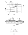
  • FIG. 2A is a plan view showing a partial configuration of the organic EL device according to Example 1 of the invention
  • FIG. 2B is a cross-sectional view taken along line 2b-2b in FIG. 2 (c) is an enlarged plan view of the fuse portion according to the embodiment of the present invention
  • 3A to 3E are plan views showing a method for manufacturing an organic EL device according to Example 1 of the invention.
  • FIGS. 4A to 4E are taken along lines 4a-4a, 4b-4b, 4c-4c, 4d-4d, and 4e-4e in FIGS. 3A to 3E, respectively. It is sectional drawing.
  • An organic electroluminescent device includes a substrate, a first electrode layer provided on the substrate, an organic functional layer including an organic material provided on the first electrode layer, and an organic functional layer.
  • the connection wiring has a fuse portion that is broken by an overcurrent, and the upper surface of the fuse portion is in contact with the gap layer. According to such a configuration, since a space is secured on the fuse portion, even if the device has a solid sealing structure, the metal constituting the fuse is scattered when an overcurrent flows through the connection wiring.
  • the gap layer blocks heat and impact when the connection wiring is disconnected, the sealing layer can be prevented from being damaged and the sealing performance can be maintained.
  • the disconnection portion in the fuse portion is connected by pressing from the sealing layer to prevent the leak from recurring. be able to.
  • FIG. 1 is a plan view showing a configuration of an organic EL device 1 according to an embodiment of the present invention.
  • 2A is an enlarged plan view showing a partial configuration of the organic EL device 1 according to the embodiment of the present invention
  • FIG. 2B is a cross-sectional view taken along line 2b-2b in FIG.
  • FIG. 2C is a plan view showing an enlarged view of the fuse portion according to the embodiment of the present invention.
  • the configuration excluding the insulating film 26 and the sealing layer 50 is shown for easy understanding.
  • the organic EL device 1 is a display device having a so-called dot matrix type display form in which each of the plurality of organic EL elements 100 functions as a pixel. That is, on the substrate 10, the plurality of power supply wirings 22 and the plurality of second electrodes 40 are arranged so as to intersect with each other, and the organic EL element 100 is disposed in the vicinity of each of these intersections.
  • Each of the organic EL elements 100 has a stacked structure in which the first electrode 20, the organic functional layer 30, and the second electrode 40 are stacked.
  • the second electrode 40 extends in a direction orthogonal to the power supply wiring 22 and is commonly used for a plurality of organic EL elements.
  • Driving power is supplied to each of the organic EL elements 100 via the power supply wiring 22 and the connection wiring 24.
  • the organic EL device 1 is a so-called bottom emission type display device that extracts light generated in the organic functional layer 30 from the substrate 10 side.
  • the substrate 10 is made of a light transmissive material such as glass.
  • the first electrode 20 provided on the substrate 10 is an anode, and a conductive metal oxide having an optical transparency such as ITO (Indium Tin Oxide) or IZO (Indium Zinc Oxide) having a thickness of about 100 nm is formed in a rectangular shape. It is formed by patterning.
  • a power supply wiring 22 for supplying driving power to the organic EL element 100 is provided on the substrate 10 so as to be separated from the first electrode 20.
  • connection wiring 24 electrically connects the power supply wiring 22 and the first electrode 20 on the substrate 10.
  • the connection wiring 24 has a disconnection function that leads to disconnection when the current injected from the power supply wiring 22 into the organic EL element 100 becomes excessive, and blocks the short-circuit current from flowing into the organic EL element 100.
  • the connection wiring 24 can be disconnected at a desired current, for example, an alloy mainly composed of tin, bismuth, lead or the like, more specifically, a solder that is a tin-based alloy, wood metal, or rose alloy , Composed of a low melting point metal such as Newton alloy.
  • connection wiring 24 has a fuse portion 24a whose line width is narrower than that of the other portion, and thereby has a current withstand capability lower than that of the other portion. That is, when the organic EL element 100 is short-circuited and an overcurrent flows through the connection wiring 24, a disconnection occurs in the fuse portion 24a.
  • the fuse portion can be configured by making the layer thickness of the connection wiring 24 smaller than that of other portions or using a material having a lower melting point. Since each organic EL element 100 is connected to the connection wiring 24 having the fuse portion 24a, even if a short circuit occurs in a specific organic EL element, damage is not spread to other organic EL elements. It has become.
  • the organic functional layer 30 is formed by laminating a hole injection layer, a hole transport layer, a light emitting layer, and an electron injection layer in this order on the first electrode 20.
  • the hole injection layer is made of, for example, copper phthalocyanine (CuPc) having a thickness of about 10 nm
  • the hole transport layer is made of, for example, ⁇ -NPD (Bis [N- (1-naphthyl) -N-pheny] benzidine) having a thickness of about 50 nm.
  • the light emitting layer is made of, for example, Alq3 (tris- (8-hydroxyquinoline) aluminum) having a thickness of about 50 nm
  • the electron injection layer is made of, for example, lithium fluoride (LiF) having a thickness of about 1 nm.
  • the second electrode 40 serving as a cathode is made of, for example, Al and is provided so as to cover the organic functional layer 30.
  • the second electrode 40 extends in a direction orthogonal to the extending direction of the power supply wiring 22.
  • the insulating layer 26 is inserted between the second electrode 40 and the power supply wiring 22 and connection wiring 24 to electrically insulate them.
  • an alloy having a relatively low work function such as Mg—Ag or Al—Li is preferable.
  • the sealing layer 50 is composed of a thin film made of an inorganic material such as SiNx, SiON, SiOx, AlOx, or AlN.
  • the sealing layer 50 covers the respective components of the organic EL device 1 described above and plays a role of preventing entry of oxygen and moisture from the outside.
  • the sealing layer 50 is formed so as to be in close contact with the organic EL element.
  • the upper surface of the fuse portion 24 a is in contact with the gap layer 60. That is, the sealing layer 50 is provided so as to avoid the fuse portion 24a, and has an opening in a portion where the fuse portion 24a is formed. The upper surface of the fuse portion 24a is exposed at this opening.
  • connection wiring 24 is connected to the first electrode 20 that is an anode.
  • connection wiring 24 may be connected to the second electrode 40 that is a cathode. In this case, it is necessary to form an insulating film between the connection wiring 24 and the first electrode 20.
  • FIGS. 3A to 3E are plan views showing a method for manufacturing the organic EL device 1 having the above-described configuration
  • FIGS. 4A to 4E are views in FIGS. 3A to 3E, respectively.
  • FIG. 4 is a cross-sectional view taken along lines 4a-4a, 4b-4b, 4c-4c, 4d-4d, and 4e-4e.
  • a light-transmitting conductive metal oxide such as ITO or IZO is deposited on the light-transmitting substrate 10 made of glass or the like by a sputtering method, for example, to a thickness of about 100 nm, and this is patterned into a rectangular shape by etching.
  • the electrode 20 is formed (FIGS. 3A and 4A).
  • a power supply wiring 22 made of a low resistance metal such as Al, Cu, Ag, Au or the like is formed on the substrate 10 at a position separated from the first electrode 20 by the same method as that for the first electrode 20.
  • alloys such as tin, bismuth, lead, etc. as the main component by mask vapor deposition, etc., more specifically, tin-based alloys such as solder, low melting point metals such as wood metal, rose alloy, and Newton alloy are used.
  • the connection wiring 24 is formed. Patterning is performed to form the fuse portion 24 a on the connection wiring 24. That is, the connection wiring 24 is patterned so that the line width is locally narrowed in the fuse portion 24a (FIGS. 3B and 4B).
  • a photosensitive resist (or polyimide) that is a material of the insulating film 26 is applied so as to cover the surfaces of the first electrode 20, the power supply wiring 22, and the connection wiring 24. Thereafter, the photosensitive resist is patterned through exposure and development. As a result, the insulating film 26 having an opening exposing the surface of the first electrode 20 and the surface of the fuse portion 24a is formed (FIGS. 3C and 4C).
  • the material of the insulating film 26 and the patterning method of the insulating film 26 are not limited to this.
  • the insulating film 26 may be an inorganic material such as SiO 2 and can be patterned by a known lift-off method or an etching method using a resist mask formed by a known photolithography technique.
  • the organic functional layer 30 is formed by sequentially forming a hole injection layer, a hole transport layer, a light emitting layer, and an electron injection layer on the exposed first electrode 20 by an inkjet method, a mask vapor deposition method, or the like.
  • the hole injection layer is made of, for example, copper phthalocyanine (CuPc) having a thickness of about 10 nm
  • the hole transport layer is made of, for example, ⁇ -NPD (Bis [N- (1-naphthyl) -N-phenyl] benzidine) having a thickness of about 50 nm.
  • the light emitting layer is made of, for example, Alq3 (tris- (8-hydroxyquinoline) aluminum) having a thickness of about 50 nm
  • the electron injection layer is made of, for example, lithium fluoride (LiF) having a thickness of about 1 nm (FIG. 3). (C), FIG. 4 (c)).
  • Al which is an electrode material
  • Al is deposited in a desired pattern on the structure obtained through each of the above steps by vapor deposition using a mask having an opening corresponding to the pattern of the second electrode 40.
  • the second electrode 40 connected to the organic functional layer 30 and extending in a direction perpendicular to the extending direction of the power supply wiring 22 is formed. That is, the organic functional layer 30 is sandwiched between the first electrode 20 and the second electrode 40, and the second electrode 40 is insulated from the power supply wiring 22 and the connection wiring 24 by the insulating layer 26 (FIG. 3D, FIG. 4 (d)).
  • the sealing layer 50 is formed by depositing an inorganic material such as SiNx, SiON, SiOx, AlOx, AlN or the like so as to entirely cover the structure obtained through the process.
  • the sealing layer 50 is formed in close contact with the organic EL element 100, and is also formed on an adhesive tape that covers the fuse portion 24a. Thereafter, the adhesive tape is peeled off, and the portion covering the fuse portion 24a of the sealing layer 50 is removed.
  • an opening of the sealing layer 50 is formed on the fuse portion 24a, and as a result, a void layer 60 is formed on the fuse portion 24a. That is, the upper surface of the fuse portion 24a is exposed at the opening of the sealing layer 50 (FIGS. 2E and 3E).
  • the organic EL device 1 is completed through the above steps.
  • the organic EL device 1 According to the organic EL device 1 according to the present embodiment, a space is formed by the air gap layer 60 above the fuse portion 24a. Therefore, the power supply wiring 22 is caused by a short circuit between the first and second electrodes.
  • the metal constituting the connection wiring 24 can be melted and evaporated with deformation and expansion, and thus the disconnection is properly achieved. be able to. Thereby, the current supply to the organic EL element 100 is interrupted. Further, since the gap layer 60 is provided on the upper surface of the fuse portion 24a, even if the connection wiring 24 is deformed or expanded in the fuse portion 24a, the sealing layer 50 is not affected.
  • the heat and impact caused by the disconnection of the connection wiring 24 are blocked by the gap layer 60, so that the sealing layer 50 is not broken and the sealing performance is maintained. Is done. Further, since the fuse portion 24a and the sealing layer 50 are not in contact with each other, the disconnection portion is connected by pressing from the sealing layer 50, and the leak does not recur.
  • FIG. 5 is a cross-sectional view showing a configuration of an organic EL device 2 according to Example 2 of the present invention.
  • the organic EL device 2 is different from the organic EL device 1 according to the first embodiment described above in that it includes banks (partition walls) 70 surrounding the void layer 60. That is, the bank 70 covers the side surface of the opening of the sealing layer 50 that defines the gap layer 60. If the sealing layer 50 is partially removed to form the gap layer 60 and an opening is provided, oxygen or moisture may enter from the opening and the organic EL device may be deteriorated.
  • the bank 70 since the bank 70 is provided so as to cover the side surface of the opening of the sealing layer 50 that defines the gap layer 60, oxygen and moisture from the opening are covered. Intrusion can be prevented.
  • Other components than the bank 70 are the same as those of the organic EL device 1 according to the first embodiment.
  • the organic EL device 2 is manufactured by the following process, for example.
  • a connection wiring 24 having a first electrode 20, a power supply wiring 22, and a fuse portion 24a is formed on the substrate 10.
  • the bank 70 is formed so as to surround the connection wiring 24 (fuse portion 24a).
  • the bank 70 is formed, for example, by depositing an organic material such as photosensitive polyimide and patterning it by an exposure / development process.
  • the bank 70 forms a partition surrounding the connection wiring 24 including the fuse portion 24a.
  • the bank 70 can be formed on the first electrode 20 and the power supply wiring 22.
  • an insulating film 26 having an opening exposing the first electrode 20 and the upper surface of the fuse portion 24a is formed.
  • the organic functional layer 30 is formed on the first electrode 20.
  • the second electrode 40 connected to the organic functional layer 30 and extending in a direction orthogonal to the extending direction of the power supply wiring 22 is formed.
  • the upper surface of the fuse portion 24a is covered with an adhesive tape or the like, and sealed with a thin film of an inorganic material so as to entirely cover the structure obtained through the above steps by plasma CVD or the like.
  • a stop layer 50 is formed.
  • the sealing layer 50 is formed in close contact with the organic EL element, and is also formed on an adhesive tape that covers the fuse portion 24a. Thereafter, the adhesive tape is peeled off to remove the portion of the sealing layer 50 that covers the fuse portion 24a, and the gap layer 60 is formed on the fuse portion 24a.
  • the organic EL device 2 is completed through the above steps.
  • the organic EL device 2 According to the organic EL device 2 according to the present embodiment, a space is formed above the fuse portion 24a due to the presence of the gap layer 60 as in the case of the above-described first embodiment, and thus the connection wiring 24 is appropriately disconnected. In addition, since the heat and impact associated with the disconnection of the connection wiring 24 are blocked by the gap layer 60, the sealing layer 50 is not destroyed and the sealing performance is maintained. Further, since the fuse portion 24a and the sealing layer 50 are not in contact with each other, the disconnection portion is connected by pressing from the sealing layer 50, and the leak does not recur. Furthermore, since the bank 70 is provided so as to cover the side surface of the opening of the sealing layer 50 that defines the gap layer 60, it is possible to prevent the intrusion of oxygen and moisture from the opening, and the organic EL It becomes possible to improve the reliability of the device.
  • FIG. 6 is a cross-sectional view showing the configuration of the organic EL device 3 according to Example 3 of the present invention.
  • the organic EL device 3 is different from the organic EL devices according to Examples 1 and 2 having a sealing structure in which sealing is performed with a thin film in that the organic EL device 3 has a sealing structure in which sealing is performed with a plate-shaped sealing plate.
  • connection wiring 24 having an organic EL element 100, a power supply wiring 22, and a fuse portion 24a is provided on the substrate 10.
  • a sealing plate 54 made of a plate material such as a glass plate, a plastic plate, or a metal plate is provided on the substrate 10 via an adhesive layer 52.
  • the adhesive layer 52 is provided so as to cover the entire area of the substrate 10 and embeds the organic EL element 100 therein.
  • the bank 70 is provided so as to surround the fuse portion 24a, and prevents the adhesive layer 52 from entering the fuse portion 24a.
  • a void layer 60 having the bank 70 as a side wall is formed on the fuse portion 24a. That is, the adhesive layer 52 forms a partial hollow structure in which the void layer 60 is embedded.
  • the organic EL device 3 is manufactured by the following process, for example.
  • a connection wiring 24 having a first electrode 20, a power supply wiring 22, and a fuse portion 24a is formed on the substrate 10.
  • the bank 70 is formed so as to surround the fuse portion 24a.
  • the bank 70 is formed, for example, by depositing an organic material such as photosensitive polyimide and patterning it by an exposure / development process.
  • the bank 70 forms a partition surrounding the connection wiring 24 including the fuse portion 24a.
  • the bank 70 can be formed on the first electrode 20 and the power supply wiring 22.
  • an insulating film 26 having an opening is formed on the first electrode 20 and the fuse portion 24a.
  • the organic functional layer 30 is formed on the first electrode 20.
  • the second electrode 40 connected to the organic functional layer 30 and extending in a direction orthogonal to the extending direction of the power supply wiring 22 is formed.
  • a sheet-like adhesive that is a material of the adhesive layer 52 is attached to the substrate 10 that has undergone the above-described steps.
  • an ultraviolet curable adhesive can be used as the sheet adhesive.
  • the ultraviolet curable sheet adhesive is a solid sheet at room temperature, can be liquefied and flowed by heating, and is completely cured instantaneously by irradiation with ultraviolet rays.
  • the sheet-like adhesive is provided on the surface of the substrate 10 so as to form a space inside the bank 70 (that is, on the fuse portion 24a). That is, the sheet-like adhesive does not enter the inside of the bank 70 and covers the upper portion of the fuse portion 24a with a gap interposed. Thereby, a partial hollow structure is formed inside the adhesive layer 52.
  • a sealing plate 54 made of a plate material such as a glass plate, a plastic plate or a metal plate is placed on the surface of the sheet adhesive. Thereafter, the adhesive is liquefied by heat treatment and then cured by ultraviolet irradiation. The organic EL device 3 is completed through the above steps.
  • the adhesive layer 52 is not limited to the above-described sheet-like adhesive, and a liquid adhesive can also be used.
  • a thermosetting or ultraviolet curable silicone resin adhesive that is a material of the adhesive layer 52 is applied and formed on the substrate 10 that has undergone each step by spin coating.
  • the component of an adhesive agent etc. are not specifically limited.
  • a partial hollow structure is formed inside the adhesive layer 52.
  • the formation of the void layer 60 is facilitated by applying a liquid repellent treatment such as a fluorine plasma treatment to the inner wall of the bank 70 and the surface of the connection wiring 24 including the fuse portion 24a.
  • a liquid repellent treatment such as a fluorine plasma treatment
  • the sealing plate 54 is placed on the adhesive layer 52, and the liquid adhesive is cured by heat treatment or ultraviolet irradiation treatment.
  • FIG. 7 is a plan view showing a configuration of the organic EL device 4 in which the arrangement of electrodes, wirings, and organic EL elements is modified.
  • connection wirings 24 are connected to one of the power supply wirings 22 formed on the substrate 10.
  • the plurality of connection wirings 24 are juxtaposed at equal intervals in a state of being collected at one place (or a plurality of places), and each has a fuse portion 24a as in the above embodiments.
  • Each of the connection wirings 24 is connected to the first electrode 20 patterned in a strip shape.
  • a strip-shaped organic functional layer 30 is also provided on the first electrode 20.
  • a second electrode 40 common to the plurality of organic EL elements 100 is provided on the organic functional layer 30. The second electrode 40 extends in parallel with the extending direction of the power supply wiring 22.
  • the 2nd electrode 40 is isolate
  • FIG. According to such a layout in which the connection wirings 24 are gathered in one place, the fuse portions 24a can be gathered in one place, so that patterning of the sealing layer (that is, formation of the void layer) is facilitated.

Abstract

A first electrode layer and a connection wiring connected to the first electrode layer are provided on a substrate. An organic functional layer comprising an organic material and a second electrode layer are stacked on the first electrode layer, configuring an organic EL element. A sealing layer is provided so as to cover the organic EL element and the connection wiring. The connection wiring has a fuse section that is disconnected by an overcurrent. The upper surface of the fuse section is in contact with an air gap layer.

Description

有機エレクトロルミネッセンスデバイスおよび有機エレクトロルミネッセンスデバイスの製造方法ORGANIC ELECTROLUMINESCENT DEVICE AND METHOD FOR PRODUCING ORGANIC ELECTROLUMINESCENT DEVICE
 本発明は、有機エレクトロルミネッセンスデバイスおよびその製造方法に関する。 The present invention relates to an organic electroluminescence device and a manufacturing method thereof.
従来技術Conventional technology
 有機エレクトロルミネッセンスデバイス(以下有機ELデバイスと称する)は、自己発光型の面発光デバイスであり、視認性が高い、低電圧駆動が可能、ブロードな発光スペクトルを有するといった理由から、ディスプレイや照明用途への実用化の研究が積極的に行われている。有機ELデバイスは、例えば、ガラス基板上に第1電極(陽極)、正孔輸送層、発光層、電子輸送層、第2電極(陰極)を順次積層して構成される。有機ELデバイスは電流注入によりエレクトロルミネッセンスを得るデバイスであり、液晶ディスプレイのような電界デバイスに比して大きな電流を流す必要がある。 An organic electroluminescence device (hereinafter referred to as an organic EL device) is a self-luminous surface light-emitting device, and has high visibility, can be driven at a low voltage, and has a broad emission spectrum. Research into the practical use of this is being actively conducted. The organic EL device is configured, for example, by sequentially laminating a first electrode (anode), a hole transport layer, a light emitting layer, an electron transport layer, and a second electrode (cathode) on a glass substrate. An organic EL device is a device that obtains electroluminescence by current injection, and requires a larger current to flow than an electric field device such as a liquid crystal display.
 有機ELデバイスでは、陽極と陰極との間に設けられる有機機能層の層厚がサブミクロンオーダーであるため、微小なゴミや有機機能層の欠陥に起因して電流リークが発生する可能性がある。例えば、ディスプレイ装置において、画素を構成する1つのセルに電流リークが生じると、周辺セルにもダメージが及ぶ可能性がある。 In the organic EL device, since the layer thickness of the organic functional layer provided between the anode and the cathode is on the order of submicron, current leakage may occur due to minute dust or defects in the organic functional layer. . For example, in a display device, if a current leak occurs in one cell that constitutes a pixel, the peripheral cell may be damaged.
 このような周辺セルへのダメージの波及を防止する技術として、特許文献1には、複数の画素の各々に、短絡時における過電流によって断線に至る断線機能を有する電極を設けることにより短絡電流を遮断する手法が記載されている。 As a technique for preventing such damage from spreading to peripheral cells, Patent Document 1 discloses that each of a plurality of pixels is provided with an electrode having a disconnection function that leads to disconnection due to an overcurrent at the time of a short circuit. A technique for blocking is described.
 特許文献2には、電極間に逆バイアス電圧を印加して電極材料を蒸発させることにより短絡箇所を自己修復する技術が記載されている。 Patent Document 2 describes a technique for self-repairing a short-circuit portion by applying a reverse bias voltage between electrodes to evaporate an electrode material.
 特許文献3には、短絡箇所にレーザを照射して溶融除去することにより、短絡箇所の修復を行う技術を開示している。 Patent Document 3 discloses a technique for repairing a short-circuited part by irradiating a laser to the short-circuited part and removing it by melting.
特開2001-196190号公報JP 2001-196190 A 特開2004-214084号公報Japanese Patent Laid-Open No. 2004-214084 特開2003-229262号公報JP 2003-229262 A
 有機ELデバイスは、酸素や水分によって急速に劣化することから封止構造を有する。封止構造としては、封止缶の如き中空封止構造が一般的である。しかしながら、近年デバイスの薄型化やフレキシブル化の要求が高まりつつあるところ、中空封止構造ではこれらの要求に対応するのが困難である。デバイスの薄型化を可能とする封止構造としては、ガラス板等の板材で封止を行う封止構造やSiO2やSiNx等の無機材料からなる薄膜で有機EL素子全体を被覆して封止する封止構造がある。このような、デバイスの構成要素に密着する板材や薄膜で封止を行う構造を固体封止構造と称する。 An organic EL device has a sealing structure because it rapidly deteriorates due to oxygen or moisture. As the sealing structure, a hollow sealing structure such as a sealing can is common. However, in recent years, there is an increasing demand for thinner and more flexible devices, and it is difficult to meet these requirements with a hollow sealing structure. The sealing structure that enables the device to be thinned includes a sealing structure that seals with a plate material such as a glass plate, or a thin film made of an inorganic material such as SiO 2 or SiN x and covers the entire organic EL element. There is a sealing structure to stop. Such a structure in which sealing is performed with a plate material or a thin film that is in close contact with the components of the device is referred to as a solid sealing structure.
 固体封止構造を有するデバイスにおいて、上記特許文献1に記載されているような過電流により断線を生じる電極を設けると、以下のような問題が生じることが考えられる。すなわち、過電流により電極が断線に至る際には電極材料は変形・膨張を伴って溶融する。固体封止構造を有するデバイスにおいては、デバイスを構成する各層が密着して形成されるため、溶融した電極材料が飛散する空間が存在しない。従って、過電流が流れても電極が適正に断線しない、または、一旦断線に至った電極が封止層からの押圧によって再度繋がって、リークが再発するおそれがある。更に、電極が断線に至る際の衝撃や熱によって封止層が破壊され、封止性能が害されるおそれがある。 When a device having a solid sealing structure is provided with an electrode that causes disconnection due to overcurrent as described in Patent Document 1, the following problems may occur. That is, when the electrode breaks due to overcurrent, the electrode material melts with deformation and expansion. In a device having a solid sealing structure, since each layer constituting the device is formed in close contact, there is no space for the molten electrode material to scatter. Therefore, even if an overcurrent flows, the electrode may not be disconnected properly, or the electrode that has once disconnected may be reconnected by pressing from the sealing layer, and the leak may recur. Furthermore, the sealing layer may be destroyed by impact or heat when the electrode is broken, and sealing performance may be impaired.
 本発明は、上記した点に鑑みてなされたものであり、過電流が流れたときに断線に至る断線機能を有する配線を備えた有機エレクトロルミネッセンスデバイスにおいて、上記断線が過電流によって適切に断線に至ることができ、且つ配線の断線に伴う熱や衝撃による封止層の損傷および封止層の押圧によるリークの再発を防止することができる有機エレクトロルミネッセンスデバイスおよびその製造方法を提供することを目的とする。 The present invention has been made in view of the above points, and in an organic electroluminescence device including a wiring having a disconnection function that leads to disconnection when an overcurrent flows, the disconnection is appropriately disconnected by overcurrent. An object of the present invention is to provide an organic electroluminescent device capable of preventing damage to the sealing layer due to heat and impact caused by disconnection of the wiring and recurrence of leakage due to pressing of the sealing layer, and a method for manufacturing the same. And
 本発明の有機エレクトロルミネッセンスデバイスは、基板と、前記基板上に設けられた第1の電極層と、前記第1の電極層の上に設けられた有機材料を含む有機機能層と、前記有機機能層の上に設けられた第2の電極層と、前記基板上に設けられて前記第1の電極層または前記第2の電極層に接続された接続配線と、前記第1の電極層、前記第2の電極層、前記有機機能層および前記接続配線を含む積層構造体を被覆する封止層と、を含み、前記接続配線は過電流により断線に至るヒューズ部を有し、前記ヒューズ部は空隙層と接していることを特徴としている。 The organic electroluminescence device of the present invention includes a substrate, a first electrode layer provided on the substrate, an organic functional layer including an organic material provided on the first electrode layer, and the organic function A second electrode layer provided on the layer, a connection wiring provided on the substrate and connected to the first electrode layer or the second electrode layer, the first electrode layer, A sealing layer that covers the laminated structure including the second electrode layer, the organic functional layer, and the connection wiring, and the connection wiring includes a fuse portion that is broken due to an overcurrent. It is characterized by being in contact with the void layer.
 また、本発明の有機エレクトロルミネッセンスデバイスの製造方法は、基板上に第1の電極層を形成する工程と、前記第1の電極層の上に有機材料を含む有機機能層を形成する工程と、前記有機機能層の上に第2の電極層を形成する工程と、前記基板上に前記第1の電極層または前記第2の電極層に接続され且つ過電流により断線に至るヒューズ部を有する接続配線を形成する工程と、前記第1の電極層、前記第2の電極層、前記有機機能層および前記接続配線を含む積層構造体を被覆するように封止層を形成する工程と、前記封止層の前記ヒューズ部の上面を覆う部分を除去する工程と、を含むことを特徴としている。 Moreover, the manufacturing method of the organic electroluminescent device of the present invention includes a step of forming a first electrode layer on a substrate, a step of forming an organic functional layer containing an organic material on the first electrode layer, A step of forming a second electrode layer on the organic functional layer, and a connection having a fuse portion connected to the first electrode layer or the second electrode layer on the substrate and being disconnected by an overcurrent A step of forming a wiring, a step of forming a sealing layer so as to cover the laminated structure including the first electrode layer, the second electrode layer, the organic functional layer, and the connection wiring, and the sealing And a step of removing a portion of the stopper layer covering the upper surface of the fuse portion.
 また、本発明の有機エレクトロルミネッセンスデバイスの製造方法は、基板上に第1の電極層を形成する工程と、前記第1の電極層の上に有機材料を含む有機機能層を形成する工程と、前記有機機能層の上に第2の電極層を形成する工程と、前記基板上に前記第1の電極層または前記第2の電極層に接続され且つ過電流により断線に至るヒューズ部を有する接続配線を形成する工程と、前記ヒューズ部を囲むバンクを形成する工程と、前記ヒューズ部上において前記バンクを側壁とする空隙層を形成しつつ前記第1の電極層、前記第2の電極層、前記有機機能層および前記接続配線を含む積層構造体を被覆する接着層を形成する工程と、前記接着層の上に封止板を形成する工程と、を含むことを特徴としている。 Moreover, the manufacturing method of the organic electroluminescent device of the present invention includes a step of forming a first electrode layer on a substrate, a step of forming an organic functional layer containing an organic material on the first electrode layer, A step of forming a second electrode layer on the organic functional layer, and a connection having a fuse portion connected to the first electrode layer or the second electrode layer on the substrate and being disconnected by an overcurrent A step of forming a wiring; a step of forming a bank surrounding the fuse portion; and forming a void layer having the bank as a side wall on the fuse portion, the first electrode layer, the second electrode layer, The method includes a step of forming an adhesive layer that covers the laminated structure including the organic functional layer and the connection wiring, and a step of forming a sealing plate on the adhesive layer.
本発明の実施例1に係る有機ELデバイスの構成を示す平面図である。It is a top view which shows the structure of the organic EL device which concerns on Example 1 of this invention. 図2(a)は本発明の実施例1に係る有機ELデバイスの部分的な構成を示す平面図、図2(b)は図2(a)における2b-2b線に沿った断面図、図2(c)は本発明の実施例に係るヒューズ部を拡大した平面図である。2A is a plan view showing a partial configuration of the organic EL device according to Example 1 of the invention, FIG. 2B is a cross-sectional view taken along line 2b-2b in FIG. 2 (c) is an enlarged plan view of the fuse portion according to the embodiment of the present invention. 図3(a)~(e)は、本発明の実施例1に係る有機ELデバイスの製造方法を示す平面図である。3A to 3E are plan views showing a method for manufacturing an organic EL device according to Example 1 of the invention. 図4(a)~(e)は、それぞれ、図3(a)~(e)における4a-4a線、4b-4b線、4c-4c線、4d-4d線、4e-4e線に沿った断面図である。FIGS. 4A to 4E are taken along lines 4a-4a, 4b-4b, 4c-4c, 4d-4d, and 4e-4e in FIGS. 3A to 3E, respectively. It is sectional drawing. 本発明の実施例2に係る有機ELデバイスの構成を示す断面図である。It is sectional drawing which shows the structure of the organic EL device which concerns on Example 2 of this invention. 本発明の実施例3に係る有機ELデバイスの構成を示す断面図である。It is sectional drawing which shows the structure of the organic EL device which concerns on Example 3 of this invention. 本発明の他の実施例に係る有機ELデバイスの構成を示す平面図である。It is a top view which shows the structure of the organic EL device which concerns on the other Example of this invention.
 本発明に係る有機エレクトロルミネッセンスデバイスは、基板と、基板上に設けられた第1の電極層と、第1の電極層の上に設けられた有機材料を含む有機機能層と、有機機能層の上に設けられた第2の電極層と、基板上に設けられて第1の電極層または第2の電極層に接続された接続配線と、第1および第2の電極層、有機機能層および接続配線を含む積層構造体を被覆する封止層と、を含む。接続配線は、過電流により断線に至るヒューズ部を有し、ヒューズ部上面が空隙層と接している。このような、構成によれば、ヒューズ部上に空間が確保される故、固体封止構造を有するデバイスであっても、接続配線に過電流が流れた場合にはヒューズを構成する金属が飛散、変形することができ、従って、適正に断線に至ることができる。また、空隙層が接続配線断線時の熱や衝撃を遮断するので、封止層の損傷を防ぐことができ、封止性能の維持が可能となる。また、ヒューズ部を含む接続配線と封止層との間には、空隙層が介在している故、封止層からの押圧によってヒューズ部における断線箇所が繋がってリークが再発することを防止することができる。 An organic electroluminescent device according to the present invention includes a substrate, a first electrode layer provided on the substrate, an organic functional layer including an organic material provided on the first electrode layer, and an organic functional layer. A second electrode layer provided on the substrate, a connection wiring provided on the substrate and connected to the first electrode layer or the second electrode layer, the first and second electrode layers, the organic functional layer, and And a sealing layer that covers the laminated structure including the connection wiring. The connection wiring has a fuse portion that is broken by an overcurrent, and the upper surface of the fuse portion is in contact with the gap layer. According to such a configuration, since a space is secured on the fuse portion, even if the device has a solid sealing structure, the metal constituting the fuse is scattered when an overcurrent flows through the connection wiring. Can be deformed, and therefore can be properly broken. In addition, since the gap layer blocks heat and impact when the connection wiring is disconnected, the sealing layer can be prevented from being damaged and the sealing performance can be maintained. In addition, since a gap layer is interposed between the connection wiring including the fuse portion and the sealing layer, the disconnection portion in the fuse portion is connected by pressing from the sealing layer to prevent the leak from recurring. be able to.
 以下、本発明の実施例について図面を参照しつつ説明する。尚、以下に示す図において、実質的に同一又は等価な構成要素、部分には同一の参照符を付している。 Hereinafter, embodiments of the present invention will be described with reference to the drawings. In the drawings shown below, substantially the same or equivalent components and parts are denoted by the same reference numerals.
 図1は、本発明の実施例に係る有機ELデバイス1の構成を示す平面図である。図2(a)は本発明の実施例に係る有機ELデバイス1の部分的な構成を示す拡大平面図、図2(b)は図2(a)における2b-2b線に沿った断面図、図2(c)は本発明の実施例に係るヒューズ部を拡大表示した平面図である。尚、図1においては、理解を容易にするために、絶縁膜26および封止層50を除いた構成が示されている。 FIG. 1 is a plan view showing a configuration of an organic EL device 1 according to an embodiment of the present invention. 2A is an enlarged plan view showing a partial configuration of the organic EL device 1 according to the embodiment of the present invention, FIG. 2B is a cross-sectional view taken along line 2b-2b in FIG. FIG. 2C is a plan view showing an enlarged view of the fuse portion according to the embodiment of the present invention. In FIG. 1, the configuration excluding the insulating film 26 and the sealing layer 50 is shown for easy understanding.
 有機ELデバイス1は、複数の有機EL素子100の各々が画素として機能する所謂ドットマトリクス方式の表示形態を有する表示デバイスである。すなわち、基板10には、複数の給電配線22と、複数の第2電極40とが互いに交差するように配置され、これらの各交差部の近傍に有機EL素子100が配置されている。有機EL素子100の各々は、第1電極20、有機機能層30、第2電極40を積層した積層構造を有する。第2電極40は、給電配線22と直交する方向に伸長しており複数の有機EL素子に共通に用いられる。有機EL素子100の各々には、給電配線22および接続配線24を介して駆動電力が供給される。有機ELデバイス1は、有機機能層30において生成された光を基板10側から取り出す所謂ボトムエミッション型の表示デバイスである。 The organic EL device 1 is a display device having a so-called dot matrix type display form in which each of the plurality of organic EL elements 100 functions as a pixel. That is, on the substrate 10, the plurality of power supply wirings 22 and the plurality of second electrodes 40 are arranged so as to intersect with each other, and the organic EL element 100 is disposed in the vicinity of each of these intersections. Each of the organic EL elements 100 has a stacked structure in which the first electrode 20, the organic functional layer 30, and the second electrode 40 are stacked. The second electrode 40 extends in a direction orthogonal to the power supply wiring 22 and is commonly used for a plurality of organic EL elements. Driving power is supplied to each of the organic EL elements 100 via the power supply wiring 22 and the connection wiring 24. The organic EL device 1 is a so-called bottom emission type display device that extracts light generated in the organic functional layer 30 from the substrate 10 side.
 基板10は、ガラス等の光透過性を有する材料により構成される。基板10上に設けられた第1電極20は陽極であり、厚さ100nm程度のITO(Indium Tin Oxide)またはIZO(Indium Zinc Oxide)等の光透過性を有する導電性金属酸化物を矩形状にパターニングすることにより形成される。また、基板10上には、有機EL素子100に駆動電力を供給するための給電配線22が第1電極20と離間して設けられている。 The substrate 10 is made of a light transmissive material such as glass. The first electrode 20 provided on the substrate 10 is an anode, and a conductive metal oxide having an optical transparency such as ITO (Indium Tin Oxide) or IZO (Indium Zinc Oxide) having a thickness of about 100 nm is formed in a rectangular shape. It is formed by patterning. A power supply wiring 22 for supplying driving power to the organic EL element 100 is provided on the substrate 10 so as to be separated from the first electrode 20.
 接続配線24は、基板10上において給電配線22と第1電極20とを電気的に接続する。接続配線24は、給電配線22から有機EL素子100に注入される電流が過大となったときに断線に至る断線機能を有し、有機EL素子100への短絡電流の流入を遮断する。接続配線24は、所望の電流で断線し得るように、例えば、スズ、ビスマス、鉛などを主成分とした合金、より具体的には、錫基の合金であるはんだや、ウッドメタル、ローズ合金、ニュートン合金などの低融点金属により構成される。また、接続配線24は、線幅が他の部分よりも狭く、これによって電流耐量が他の部分よりも低くなっているヒューズ部24aを有する。すなわち、有機EL素子100が短絡し、接続配線24に過電流が流れた場合、ヒューズ部24aにおいて断線が生じるようになっている。尚、接続配線24において層厚を他の部分よりも小さくしたり、より融点の低い材料を用いることによりヒューズ部を構成することも可能である。各有機EL素子100にはヒューズ部24aを有する接続配線24が接続されているので、特定の有機EL素子に短絡が生じた場合であっても、他の有機EL素子に被害が波及しないようになっている。 The connection wiring 24 electrically connects the power supply wiring 22 and the first electrode 20 on the substrate 10. The connection wiring 24 has a disconnection function that leads to disconnection when the current injected from the power supply wiring 22 into the organic EL element 100 becomes excessive, and blocks the short-circuit current from flowing into the organic EL element 100. The connection wiring 24 can be disconnected at a desired current, for example, an alloy mainly composed of tin, bismuth, lead or the like, more specifically, a solder that is a tin-based alloy, wood metal, or rose alloy , Composed of a low melting point metal such as Newton alloy. In addition, the connection wiring 24 has a fuse portion 24a whose line width is narrower than that of the other portion, and thereby has a current withstand capability lower than that of the other portion. That is, when the organic EL element 100 is short-circuited and an overcurrent flows through the connection wiring 24, a disconnection occurs in the fuse portion 24a. It is to be noted that the fuse portion can be configured by making the layer thickness of the connection wiring 24 smaller than that of other portions or using a material having a lower melting point. Since each organic EL element 100 is connected to the connection wiring 24 having the fuse portion 24a, even if a short circuit occurs in a specific organic EL element, damage is not spread to other organic EL elements. It has become.
 有機機能層30は、第1電極20上にホール注入層、ホール輸送層、発光層、電子注入層をこの順で積層することにより形成される。ホール注入層は例えば厚さ10nm程度の銅フタロシアニン(CuPc)により構成され、ホール輸送層は例えば厚さ50nm程度のα-NPD(Bis[N-(1-naphthyl)-N-pheny]benzidine)により構成され、発光層は例えば厚さ50nm程度のAlq3(tris-(8-hydroxyquinoline)aluminum)により構成され、電子注入層は例えば厚さ1nm程度のフッ化リチウム(LiF)により構成される。 The organic functional layer 30 is formed by laminating a hole injection layer, a hole transport layer, a light emitting layer, and an electron injection layer in this order on the first electrode 20. The hole injection layer is made of, for example, copper phthalocyanine (CuPc) having a thickness of about 10 nm, and the hole transport layer is made of, for example, α-NPD (Bis [N- (1-naphthyl) -N-pheny] benzidine) having a thickness of about 50 nm. The light emitting layer is made of, for example, Alq3 (tris- (8-hydroxyquinoline) aluminum) having a thickness of about 50 nm, and the electron injection layer is made of, for example, lithium fluoride (LiF) having a thickness of about 1 nm.
 陰極である第2電極40は、例えばAl等からなり、有機機能層30を覆うように設けられる。第2電極40は、給電配線22の伸長方向に対して直交する方向に伸長している。絶縁層26は、第2電極40と、給電配線22および接続配線24との間に挿入され、これらを電気的に絶縁する。第2電極40の他の材料としては、Mg-AgやAl-Li等の比較的仕事関数の低い合金が好適である。 The second electrode 40 serving as a cathode is made of, for example, Al and is provided so as to cover the organic functional layer 30. The second electrode 40 extends in a direction orthogonal to the extending direction of the power supply wiring 22. The insulating layer 26 is inserted between the second electrode 40 and the power supply wiring 22 and connection wiring 24 to electrically insulate them. As another material of the second electrode 40, an alloy having a relatively low work function such as Mg—Ag or Al—Li is preferable.
 封止層50は、SiNx、SiON、SiOx、AlOx、AlN等の無機材料からなる薄膜により構成される。封止層50は、上記した有機ELデバイス1の各構成部分を全体的に覆い、外部からの酸素や水分の侵入を防止する役割を担う。封止層50は、有機EL素子に密着するように形成される。一方、ヒューズ部24aの上面は空隙層60と接している。すなわち、封止層50は、ヒューズ部24aを回避するように設けられ、ヒューズ部24aの形成部分において開口部を有する。ヒューズ部24aの上面は、この開口部において露出している。 The sealing layer 50 is composed of a thin film made of an inorganic material such as SiNx, SiON, SiOx, AlOx, or AlN. The sealing layer 50 covers the respective components of the organic EL device 1 described above and plays a role of preventing entry of oxygen and moisture from the outside. The sealing layer 50 is formed so as to be in close contact with the organic EL element. On the other hand, the upper surface of the fuse portion 24 a is in contact with the gap layer 60. That is, the sealing layer 50 is provided so as to avoid the fuse portion 24a, and has an opening in a portion where the fuse portion 24a is formed. The upper surface of the fuse portion 24a is exposed at this opening.
 尚、上記した例では、接続配線24は、陽極である第1電極20に接続される構成としたが、接続配線24は、陰極である第2電極40に接続されていてもよい。この場合、接続配線24と第1電極20との間に絶縁膜を形成する必要がある。 In the above example, the connection wiring 24 is connected to the first electrode 20 that is an anode. However, the connection wiring 24 may be connected to the second electrode 40 that is a cathode. In this case, it is necessary to form an insulating film between the connection wiring 24 and the first electrode 20.
 図3(a)~(e)は、上記した構成を有する有機ELデバイス1の製造方法を示す平面図、図4(a)~(e)はそれぞれ、図3(a)~(e)における4a-4a線、4b-4b線、4c-4c線、4d-4d線、4e-4e線に沿った断面図である。 FIGS. 3A to 3E are plan views showing a method for manufacturing the organic EL device 1 having the above-described configuration, and FIGS. 4A to 4E are views in FIGS. 3A to 3E, respectively. FIG. 4 is a cross-sectional view taken along lines 4a-4a, 4b-4b, 4c-4c, 4d-4d, and 4e-4e.
 ガラス等からなる光透過性を有する基板10上に例えばスパッタ法によりITOやIZO等の光透過性を有する導電性金属酸化物を100nm程度堆積させ、エッチングによりこれを矩形状にパターニングして第1電極20を形成する(図3(a)、図4(a))。 A light-transmitting conductive metal oxide such as ITO or IZO is deposited on the light-transmitting substrate 10 made of glass or the like by a sputtering method, for example, to a thickness of about 100 nm, and this is patterned into a rectangular shape by etching. The electrode 20 is formed (FIGS. 3A and 4A).
 次に、第1電極20の場合と同様の手法により、基板10上にAl、Cu、Ag、Au等の低抵抗金属からなる給電配線22を第1電極20から離間した位置に形成する。続いて、マスク蒸着法などによりスズ、ビスマス、鉛などを主成分とした合金、より具体的には、錫基の合金であるはんだや、ウッドメタル、ローズ合金、ニュートン合金などの低融点金属からなる接続配線24を形成する。接続配線24上にヒューズ部24aを形成するべくパターニングを行う。すなわち、接続配線24は、ヒューズ部24aにおいて線幅が局所的に狭くなるようにパターニングされる(図3(b)、図4(b))。 Next, a power supply wiring 22 made of a low resistance metal such as Al, Cu, Ag, Au or the like is formed on the substrate 10 at a position separated from the first electrode 20 by the same method as that for the first electrode 20. Subsequently, alloys such as tin, bismuth, lead, etc. as the main component by mask vapor deposition, etc., more specifically, tin-based alloys such as solder, low melting point metals such as wood metal, rose alloy, and Newton alloy are used. The connection wiring 24 is formed. Patterning is performed to form the fuse portion 24 a on the connection wiring 24. That is, the connection wiring 24 is patterned so that the line width is locally narrowed in the fuse portion 24a (FIGS. 3B and 4B).
 次に、第1電極20、給電配線22、接続配線24の表面を覆うように絶縁膜26の材料である感光性レジスト(又はポリイミド)を塗布する。その後、露光、現像処理を経て、感光性レジストをパターニングする。これにより、第1電極20の表面およびヒューズ部24aの表面を露出せしめる開口部を有する絶縁膜26が形成される(図3(c)、図4(c))。尚、絶縁膜26の材料や、絶縁膜26のパターニング方法は、これに限定されるものではない。例えば、絶縁膜26はSiO2などの無機材料であってもよく、公知のリフトオフ法や、公知のフォトリソグラフィ技術で形成されたレジストマスクを用いたエッチング法によりパターニングすることも可能である。 Next, a photosensitive resist (or polyimide) that is a material of the insulating film 26 is applied so as to cover the surfaces of the first electrode 20, the power supply wiring 22, and the connection wiring 24. Thereafter, the photosensitive resist is patterned through exposure and development. As a result, the insulating film 26 having an opening exposing the surface of the first electrode 20 and the surface of the fuse portion 24a is formed (FIGS. 3C and 4C). The material of the insulating film 26 and the patterning method of the insulating film 26 are not limited to this. For example, the insulating film 26 may be an inorganic material such as SiO 2 and can be patterned by a known lift-off method or an etching method using a resist mask formed by a known photolithography technique.
 次に、インクジェット法やマスク蒸着法等により、露出した第1電極20上にホール注入層、ホール輸送層、発光層、電子注入層を順次成膜して有機機能層30を形成する。ホール注入層は例えば厚さ10nm程度の銅フタロシアニン(CuPc)により構成され、ホール輸送層は例えば厚さ50nm程度のα-NPD (Bis[N-(1-naphthyl)-N-phenyl]benzidine)により構成され、発光層は例えば厚さ50nm程度のAlq3(tris-(8-hydroxyquinoline)aluminum)により構成され、電子注入層は例えば厚さ1nm程度のフッ化リチウム(LiF)により構成される(図3(c)、図4(c))。 Next, the organic functional layer 30 is formed by sequentially forming a hole injection layer, a hole transport layer, a light emitting layer, and an electron injection layer on the exposed first electrode 20 by an inkjet method, a mask vapor deposition method, or the like. The hole injection layer is made of, for example, copper phthalocyanine (CuPc) having a thickness of about 10 nm, and the hole transport layer is made of, for example, α-NPD (Bis [N- (1-naphthyl) -N-phenyl] benzidine) having a thickness of about 50 nm. The light emitting layer is made of, for example, Alq3 (tris- (8-hydroxyquinoline) aluminum) having a thickness of about 50 nm, and the electron injection layer is made of, for example, lithium fluoride (LiF) having a thickness of about 1 nm (FIG. 3). (C), FIG. 4 (c)).
 次に、第2電極40のパターンに対応する開口部を有するマスクを用いて蒸着法等により上記各工程を経て得られた構造体の上に電極材料であるAlを所望のパターンに堆積させる。これにより、有機機能層30に接続され且つ給電配線22の伸長方向と直交する方向に伸長する第2電極40が形成される。すなわち、有機機能層30は、第1電極20と第2電極40に挟持され、第2電極40は、絶縁層26により給電配線22および接続配線24から絶縁される(図3(d)、図4(d))。 Next, Al, which is an electrode material, is deposited in a desired pattern on the structure obtained through each of the above steps by vapor deposition using a mask having an opening corresponding to the pattern of the second electrode 40. Thereby, the second electrode 40 connected to the organic functional layer 30 and extending in a direction perpendicular to the extending direction of the power supply wiring 22 is formed. That is, the organic functional layer 30 is sandwiched between the first electrode 20 and the second electrode 40, and the second electrode 40 is insulated from the power supply wiring 22 and the connection wiring 24 by the insulating layer 26 (FIG. 3D, FIG. 4 (d)).
 次に、絶縁膜26の開口部において露出しているヒューズ部24aの上面を粘着テープ等を用いてカバーしておき、等方的な成膜が可能なプラズマCVD法などにより、上記各工程を経て得られた構造体を全体的に覆うようにSiNx、SiON、SiOx、AlOx、AlN等の無機材料を堆積させて封止層50を形成する。封止層50は、有機EL素子100に密着して形成され、ヒューズ部24aを覆う粘着テープの上にも形成される。その後、粘着テープを剥離して封止層50のヒューズ部24aを覆う部分を除去する。これにより、ヒューズ部24a上に封止層50の開口部が形成され、その結果、ヒューズ部24a上に空隙層60が形成される。すなわち、ヒューズ部24aの上面は、封止層50の開口部において露出している(図2(e)、図3(e))。以上の各工程を経ることにより有機ELデバイス1が完成する。 Next, the upper surface of the fuse portion 24a exposed at the opening of the insulating film 26 is covered with an adhesive tape or the like, and the above steps are performed by a plasma CVD method or the like capable of isotropic film formation. The sealing layer 50 is formed by depositing an inorganic material such as SiNx, SiON, SiOx, AlOx, AlN or the like so as to entirely cover the structure obtained through the process. The sealing layer 50 is formed in close contact with the organic EL element 100, and is also formed on an adhesive tape that covers the fuse portion 24a. Thereafter, the adhesive tape is peeled off, and the portion covering the fuse portion 24a of the sealing layer 50 is removed. As a result, an opening of the sealing layer 50 is formed on the fuse portion 24a, and as a result, a void layer 60 is formed on the fuse portion 24a. That is, the upper surface of the fuse portion 24a is exposed at the opening of the sealing layer 50 (FIGS. 2E and 3E). The organic EL device 1 is completed through the above steps.
 本実施例に係る有機ELデバイス1によれば、ヒューズ部24aの上方には、空隙層60によって空間が形成される故、第1および第2電極間のショート等に起因して、給電配線22から接続配線24を経由して有機EL素子100に過電流が流れた場合、接続配線24を構成する金属が、変形・膨張を伴って溶融・蒸発することができ、従って、適正に断線に至ることができる。これにより、有機EL素子100への電流供給が遮断される。また、ヒューズ部24aの上面には、空隙層60が設けられている故、接続配線24がヒューズ部24aにおいて変形・膨張しても封止層50にその影響は及ばない。このように、本実施例に係る有機ELデバイスによれば、接続配線24の断線に伴う熱や衝撃は空隙層60によって遮断されるので、封止層50は破壊されず、封止性能が維持される。また、ヒューズ部24aと封止層50は非接触である故、封止層50からの押圧によって断線箇所が繋がってリークが再発することもない。 According to the organic EL device 1 according to the present embodiment, a space is formed by the air gap layer 60 above the fuse portion 24a. Therefore, the power supply wiring 22 is caused by a short circuit between the first and second electrodes. When an overcurrent flows to the organic EL element 100 through the connection wiring 24, the metal constituting the connection wiring 24 can be melted and evaporated with deformation and expansion, and thus the disconnection is properly achieved. be able to. Thereby, the current supply to the organic EL element 100 is interrupted. Further, since the gap layer 60 is provided on the upper surface of the fuse portion 24a, even if the connection wiring 24 is deformed or expanded in the fuse portion 24a, the sealing layer 50 is not affected. As described above, according to the organic EL device according to the present embodiment, the heat and impact caused by the disconnection of the connection wiring 24 are blocked by the gap layer 60, so that the sealing layer 50 is not broken and the sealing performance is maintained. Is done. Further, since the fuse portion 24a and the sealing layer 50 are not in contact with each other, the disconnection portion is connected by pressing from the sealing layer 50, and the leak does not recur.
 図5は、本発明の実施例2に係る有機ELデバイス2の構成を示す断面図である。有機ELデバイス2は、空隙層60の周囲を囲むバンク(隔壁部)70を有する点が上記した実施例1に係る有機ELデバイス1と異なる。すなわち、バンク70は、空隙層60を画定している封止層50の開口部の側面を覆っている。空隙層60を形成するべく封止層50を部分的に除去して開口部を設けると、その開口部から酸素や水分が浸入して有機ELデバイスが劣化するおそれがある。本実施例に係る有機ELデバイス2によれば、空隙層60を画定する封止層50の開口部の側面を覆うようにバンク70が設けられているので、当該開口部からの酸素や水分の浸入を防止することが可能となる。バンク70以外の他の構成部分は、上記した実施例1に係る有機ELデバイス1と同様である。 FIG. 5 is a cross-sectional view showing a configuration of an organic EL device 2 according to Example 2 of the present invention. The organic EL device 2 is different from the organic EL device 1 according to the first embodiment described above in that it includes banks (partition walls) 70 surrounding the void layer 60. That is, the bank 70 covers the side surface of the opening of the sealing layer 50 that defines the gap layer 60. If the sealing layer 50 is partially removed to form the gap layer 60 and an opening is provided, oxygen or moisture may enter from the opening and the organic EL device may be deteriorated. According to the organic EL device 2 according to the present embodiment, since the bank 70 is provided so as to cover the side surface of the opening of the sealing layer 50 that defines the gap layer 60, oxygen and moisture from the opening are covered. Intrusion can be prevented. Other components than the bank 70 are the same as those of the organic EL device 1 according to the first embodiment.
 有機ELデバイス2は、例えば以下のようなプロセスで製造される。基板10上に第1電極20、給電配線22、ヒューズ部24aを有する接続配線24を形成する。次に、接続配線24(ヒューズ部24a)を囲むようにバンク70を形成する。バンク70は、例えば感光性ポリイミド等の有機材料を成膜した後、露光・現像プロセスによってパターニングすることにより形成される。バンク70は、ヒューズ部24aを含む接続配線24を囲む隔壁を形成する。バンク70は例えば第1電極20および給電配線22上に形成することができる。次に、第1電極20およびヒューズ部24a上面を露出せしめる開口部を有する絶縁膜26を形成する。次に、第1電極20上に有機機能層30を形成する。次に、有機機能層30に接続され且つ給電配線22の伸長方向と直交する方向に伸長する第2電極40を形成する。 The organic EL device 2 is manufactured by the following process, for example. A connection wiring 24 having a first electrode 20, a power supply wiring 22, and a fuse portion 24a is formed on the substrate 10. Next, the bank 70 is formed so as to surround the connection wiring 24 (fuse portion 24a). The bank 70 is formed, for example, by depositing an organic material such as photosensitive polyimide and patterning it by an exposure / development process. The bank 70 forms a partition surrounding the connection wiring 24 including the fuse portion 24a. For example, the bank 70 can be formed on the first electrode 20 and the power supply wiring 22. Next, an insulating film 26 having an opening exposing the first electrode 20 and the upper surface of the fuse portion 24a is formed. Next, the organic functional layer 30 is formed on the first electrode 20. Next, the second electrode 40 connected to the organic functional layer 30 and extending in a direction orthogonal to the extending direction of the power supply wiring 22 is formed.
 次に、ヒューズ部24aの上面を粘着テープ等を用いてカバーしておき、プラズマCVD法などにより、上記各工程を経て得られた構造体を全体的に覆うように無機材料の薄膜からなる封止層50を形成する。封止層50は、有機EL素子に密着して形成され、ヒューズ部24aを覆う粘着テープの上にも形成される。その後、粘着テープを剥離して封止層50のヒューズ部24aを覆う部分を除去してヒューズ部24a上に空隙層60を形成する。以上の各工程を経ることにより有機ELデバイス2が完成する。 Next, the upper surface of the fuse portion 24a is covered with an adhesive tape or the like, and sealed with a thin film of an inorganic material so as to entirely cover the structure obtained through the above steps by plasma CVD or the like. A stop layer 50 is formed. The sealing layer 50 is formed in close contact with the organic EL element, and is also formed on an adhesive tape that covers the fuse portion 24a. Thereafter, the adhesive tape is peeled off to remove the portion of the sealing layer 50 that covers the fuse portion 24a, and the gap layer 60 is formed on the fuse portion 24a. The organic EL device 2 is completed through the above steps.
 本実施例に係る有機ELデバイス2によれば、上記した実施例1の場合と同様、空隙層60の存在によってヒューズ部24aの上方に空間が形成される故、接続配線24は適正に断線に至ることができ、また、接続配線24の断線に伴う熱や衝撃は空隙層60によって遮断されるので、封止層50は破壊されず、封止性能が維持される。また、ヒューズ部24aと封止層50は非接触である故、封止層50からの押圧によって断線箇所が繋がってリークが再発することもない。更に、空隙層60を画定する封止層50の開口部の側面を覆うようにバンク70が設けられているので、当該開口部からの酸素や水分の浸入を防止することが可能となり、有機ELデバイスの信頼性を向上させることが可能となる。 According to the organic EL device 2 according to the present embodiment, a space is formed above the fuse portion 24a due to the presence of the gap layer 60 as in the case of the above-described first embodiment, and thus the connection wiring 24 is appropriately disconnected. In addition, since the heat and impact associated with the disconnection of the connection wiring 24 are blocked by the gap layer 60, the sealing layer 50 is not destroyed and the sealing performance is maintained. Further, since the fuse portion 24a and the sealing layer 50 are not in contact with each other, the disconnection portion is connected by pressing from the sealing layer 50, and the leak does not recur. Furthermore, since the bank 70 is provided so as to cover the side surface of the opening of the sealing layer 50 that defines the gap layer 60, it is possible to prevent the intrusion of oxygen and moisture from the opening, and the organic EL It becomes possible to improve the reliability of the device.
 図6は、本発明の実施例3に係る有機ELデバイス3の構成を示す断面図である。有機ELデバイス3は、板状の封止板で封止を行う封止構造を有する点が薄膜で封止を行う封止構造を有する上記実施例1および2に係る有機ELデバイスと異なる。 FIG. 6 is a cross-sectional view showing the configuration of the organic EL device 3 according to Example 3 of the present invention. The organic EL device 3 is different from the organic EL devices according to Examples 1 and 2 having a sealing structure in which sealing is performed with a thin film in that the organic EL device 3 has a sealing structure in which sealing is performed with a plate-shaped sealing plate.
 基板10上には、有機EL素子100、給電配線22およびヒューズ部24aを有する接続配線24が設けられている。基板10上には接着層52を介して例えばガラス板、プラスチック板または金属板等の板材からなる封止板54が設けられている。接着層52は、基板10の全域を覆うように設けられ、有機EL素子100を内部に埋設する。バンク70はヒューズ部24aを囲むように設けられ、ヒューズ部24a上への接着層52の侵入を阻止している。これにより、ヒューズ部24a上にバンク70を側壁とする空隙層60が形成される。すなわち、接着層52は、内部に空隙層60を包埋する部分的な中空構造を形成している。 On the substrate 10, a connection wiring 24 having an organic EL element 100, a power supply wiring 22, and a fuse portion 24a is provided. A sealing plate 54 made of a plate material such as a glass plate, a plastic plate, or a metal plate is provided on the substrate 10 via an adhesive layer 52. The adhesive layer 52 is provided so as to cover the entire area of the substrate 10 and embeds the organic EL element 100 therein. The bank 70 is provided so as to surround the fuse portion 24a, and prevents the adhesive layer 52 from entering the fuse portion 24a. As a result, a void layer 60 having the bank 70 as a side wall is formed on the fuse portion 24a. That is, the adhesive layer 52 forms a partial hollow structure in which the void layer 60 is embedded.
 有機ELデバイス3は、例えば以下のようなプロセスで製造される。基板10上に第1電極20、給電配線22、ヒューズ部24aを有する接続配線24を形成する。次に、ヒューズ部24aを囲むようにバンク70を形成する。バンク70は、例えば感光性ポリイミド等の有機材料を成膜した後、露光・現像プロセスによってパターニングすることにより形成される。バンク70は、ヒューズ部24aを含む接続配線24を囲む隔壁を形成する。バンク70は例えば第1電極20および給電配線22上に形成することができる。 The organic EL device 3 is manufactured by the following process, for example. A connection wiring 24 having a first electrode 20, a power supply wiring 22, and a fuse portion 24a is formed on the substrate 10. Next, the bank 70 is formed so as to surround the fuse portion 24a. The bank 70 is formed, for example, by depositing an organic material such as photosensitive polyimide and patterning it by an exposure / development process. The bank 70 forms a partition surrounding the connection wiring 24 including the fuse portion 24a. For example, the bank 70 can be formed on the first electrode 20 and the power supply wiring 22.
 次に、第1電極20およびヒューズ部24a上において開口部を有する絶縁膜26を形成する。次に、第1電極20上に有機機能層30を形成する。次に、有機機能層30に接続され且つ給電配線22の伸長方向と直交する方向に伸長する第2電極40を形成する。 Next, an insulating film 26 having an opening is formed on the first electrode 20 and the fuse portion 24a. Next, the organic functional layer 30 is formed on the first electrode 20. Next, the second electrode 40 connected to the organic functional layer 30 and extending in a direction orthogonal to the extending direction of the power supply wiring 22 is formed.
 次に、上記各工程を経た基板10上に接着層52の材料であるシート状接着剤を貼り付ける。シート状接着剤として例えば紫外線硬化型のものを使用することができる。紫外線硬化型のシート接着剤は、常温では固体シート状であり、加熱することで液化流動することができ、紫外線を照射することによって瞬時に完全硬化する。シート状接着剤は、バンク70の内側(すなわち、ヒューズ部24a上)に空間を形成するように基板10の表面に設けられる。すなわち、シート状接着剤はバンク70の内側に侵入することなく、ヒューズ部24aの上方を空隙を介在させた状態で覆う。これにより、接着層52の内部に部分的な中空構造が形成される。 Next, a sheet-like adhesive that is a material of the adhesive layer 52 is attached to the substrate 10 that has undergone the above-described steps. For example, an ultraviolet curable adhesive can be used as the sheet adhesive. The ultraviolet curable sheet adhesive is a solid sheet at room temperature, can be liquefied and flowed by heating, and is completely cured instantaneously by irradiation with ultraviolet rays. The sheet-like adhesive is provided on the surface of the substrate 10 so as to form a space inside the bank 70 (that is, on the fuse portion 24a). That is, the sheet-like adhesive does not enter the inside of the bank 70 and covers the upper portion of the fuse portion 24a with a gap interposed. Thereby, a partial hollow structure is formed inside the adhesive layer 52.
 続いて、シート状接着剤の表面にガラス板、プラスチック板または金属板等の板材からなる封止板54を載置する。その後、熱処理によって接着剤を液化させた後、紫外線照射によってこれを硬化させる。以上の各工程を経ることにより有機ELデバイス3が完成する。 Subsequently, a sealing plate 54 made of a plate material such as a glass plate, a plastic plate or a metal plate is placed on the surface of the sheet adhesive. Thereafter, the adhesive is liquefied by heat treatment and then cured by ultraviolet irradiation. The organic EL device 3 is completed through the above steps.
 尚、接着層52は、上記したようなシート状接着剤に限らず、液状の接着剤を用いることも可能である。例えば、スピンコート法により各工程を経た基板10上に接着層52の材料である熱硬化型または紫外線硬化型のシリコーン樹脂接着剤を塗布成膜する。尚、接着剤の成分等は特に限定されるものではない。また、接着剤に酸化バリウム粉末を含有させて接着層52に吸湿機能を持たせることとしてもよい。接着剤の粘度等を調整することにより、接着剤はバンク70の内側に侵入することなく、ヒューズ部24aの上方を覆う。すなわち、接着剤はヒューズ部24aの上方において空隙層60を形成しつつ濡れ拡がる。これにより、接着層52の内部に部分的な中空構造が形成される。尚、バンク70の内壁やヒューズ部24aを含む接続配線24の表面にフッ素系プラズマ処理等の撥液性処理を施すことにより、空隙層60の形成が容易となる。その後、接着層52上に封止板54を載置して、熱処理または紫外線照射処理などによって液状の接着剤を硬化させる。 In addition, the adhesive layer 52 is not limited to the above-described sheet-like adhesive, and a liquid adhesive can also be used. For example, a thermosetting or ultraviolet curable silicone resin adhesive that is a material of the adhesive layer 52 is applied and formed on the substrate 10 that has undergone each step by spin coating. In addition, the component of an adhesive agent etc. are not specifically limited. Moreover, it is good also as making an adhesive agent contain barium oxide powder and making the adhesive layer 52 have a moisture absorption function. By adjusting the viscosity or the like of the adhesive, the adhesive covers the upper portion of the fuse portion 24 a without entering the inside of the bank 70. That is, the adhesive spreads wet while forming the void layer 60 above the fuse portion 24a. Thereby, a partial hollow structure is formed inside the adhesive layer 52. The formation of the void layer 60 is facilitated by applying a liquid repellent treatment such as a fluorine plasma treatment to the inner wall of the bank 70 and the surface of the connection wiring 24 including the fuse portion 24a. Thereafter, the sealing plate 54 is placed on the adhesive layer 52, and the liquid adhesive is cured by heat treatment or ultraviolet irradiation treatment.
 このような、板状の封止板で封止を行う封止構造を有する有機ELデバイスにおいても薄膜で封止を行う場合と同様、過電流が流れた場合、接続配線は、適正に断線に至ることができ、また、接続配線24の断線に伴う熱や衝撃は空隙層60によって遮断されるので、封止板54は破壊されず、封止性能が維持される。また、ヒューズ部24aと封止板54は非接触である故、封止板54からの押圧によって断線箇所が繋がってリークが再発することもない。 In such an organic EL device having a sealing structure for sealing with a plate-shaped sealing plate, as in the case of sealing with a thin film, when an overcurrent flows, the connection wiring is properly disconnected. In addition, since the heat and impact associated with the disconnection of the connection wiring 24 are blocked by the gap layer 60, the sealing plate 54 is not destroyed and the sealing performance is maintained. Further, since the fuse portion 24a and the sealing plate 54 are not in contact with each other, the disconnection portion is not connected by the pressing from the sealing plate 54 and the leak does not recur.
 上記各実施例においては、給電配線22と第2電極40とを格子状に配列し、これらの各交差部に有機EL素子100を配置する所謂ドットマトリックスの表示形態を有する表示デバイスを例に説明したが、本発明は、そのような構成に限定されるものではない。図7は、電極、配線および有機EL素子の配置が改変された有機ELデバイス4の構成を示す平面図である。 In each of the above-described embodiments, a display device having a so-called dot matrix display mode in which the power supply wiring 22 and the second electrode 40 are arranged in a grid pattern and the organic EL elements 100 are arranged at the respective intersections will be described as an example. However, the present invention is not limited to such a configuration. FIG. 7 is a plan view showing a configuration of the organic EL device 4 in which the arrangement of electrodes, wirings, and organic EL elements is modified.
 有機ELデバイス4において、基板10上に形成された給電配線22の1つに、複数の接続配線24が接続されている。複数の接続配線24は、1箇所(または複数個所)にまとめられた状態で等間隔に並置され、それぞれ、上記各実施例と同様、ヒューズ部24aを有する。接続配線24の各々は、短冊状にパターニングされた第1電極20に接続されている。第1電極20上には、同じく短冊状の有機機能層30が設けられている。有機機能層30上には複数の有機EL素子100に共通の第2電極40が設けられている。第2電極40は、給電配線22の伸長方向と平行に伸長している。尚、第2電極40は、有機EL素子毎に 分離され、第1電極20や有機機能層30と同様、短冊形状を有していてもよい。このような接続配線24を1箇所に集約したレイアウトによれば、ヒューズ部24aを1箇所にまとめることができるので、封止層のパターニング(すなわち空隙層の形成)が容易となる。 In the organic EL device 4, a plurality of connection wirings 24 are connected to one of the power supply wirings 22 formed on the substrate 10. The plurality of connection wirings 24 are juxtaposed at equal intervals in a state of being collected at one place (or a plurality of places), and each has a fuse portion 24a as in the above embodiments. Each of the connection wirings 24 is connected to the first electrode 20 patterned in a strip shape. A strip-shaped organic functional layer 30 is also provided on the first electrode 20. A second electrode 40 common to the plurality of organic EL elements 100 is provided on the organic functional layer 30. The second electrode 40 extends in parallel with the extending direction of the power supply wiring 22. In addition, the 2nd electrode 40 is isolate | separated for every organic EL element, and may have a strip shape similarly to the 1st electrode 20 and the organic functional layer 30. FIG. According to such a layout in which the connection wirings 24 are gathered in one place, the fuse portions 24a can be gathered in one place, so that patterning of the sealing layer (that is, formation of the void layer) is facilitated.
 1、2、3、4 有機ELデバイス
 10 基板
 20 第1電極
 22 給電配線
 24 接続配線
 24a ヒューズ部
 30 有機機能層
 40 第2電極
 50 封止層
 52 接着層
 54 封止板
 60 空隙含有層
 70 バンク
1, 2, 3, 4 Organic EL device 10 Substrate 20 First electrode 22 Power supply wiring 24 Connection wiring 24a Fuse portion 30 Organic functional layer 40 Second electrode 50 Sealing layer 52 Adhesive layer 54 Sealing plate 60 Void-containing layer 70 Bank

Claims (8)

  1.  基板と、
     前記基板上に設けられた第1の電極層と、
     前記第1の電極層の上に設けられた有機材料を含む有機機能層と、
     前記有機機能層の上に設けられた第2の電極層と、
     前記基板上に設けられて前記第1の電極層または前記第2の電極層に接続された接続配線と、
     前記第1の電極層、前記第2の電極層、前記有機機能層および前記接続配線を含む積層構造体を被覆する封止層と、を含み、
     前記接続配線は過電流により断線に至るヒューズ部を有し、前記ヒューズ部は空隙層と接していることを特徴とする有機エレクトロルミネッセンスデバイス。
    A substrate,
    A first electrode layer provided on the substrate;
    An organic functional layer containing an organic material provided on the first electrode layer;
    A second electrode layer provided on the organic functional layer;
    A connection wiring provided on the substrate and connected to the first electrode layer or the second electrode layer;
    A sealing layer covering the laminated structure including the first electrode layer, the second electrode layer, the organic functional layer, and the connection wiring,
    2. The organic electroluminescence device according to claim 1, wherein the connection wiring has a fuse portion that is broken by an overcurrent, and the fuse portion is in contact with the air gap layer.
  2.  前記封止層は、前記空隙層を画定する開口部を有し、
     前記ヒューズの上面は前記開口部において前記封止層から露出していることを特徴とする請求項1に記載の有機エレクトロルミネッセンスデバイス。
    The sealing layer has an opening that defines the void layer;
    The organic electroluminescence device according to claim 1, wherein an upper surface of the fuse is exposed from the sealing layer in the opening.
  3.  前記封止層の前記開口部の側面を覆うバンクを更に有することを特徴とする請求項2に記載の有機エレクトロルミネッセンスデバイス。 The organic electroluminescence device according to claim 2, further comprising a bank that covers a side surface of the opening of the sealing layer.
  4.  前記封止層は、薄膜により構成されていることを特徴とする請求項1乃至3のいずれか1つに記載の有機エレクトロルミネッセンスデバイス。 The organic electroluminescence device according to any one of claims 1 to 3, wherein the sealing layer is formed of a thin film.
  5.  前記封止層は、前記基板上において前記空隙層を包埋するように形成された接着層と、前記接着層の上に設けられた封止板により構成されていることを特徴とする請求項1乃至3のいずれか1つに記載の有機エレクトロルミネッセンスデバイス。 The said sealing layer is comprised by the contact bonding layer formed so that the said space | gap layer might be embedded on the said board | substrate, and the sealing board provided on the said contact bonding layer. The organic electroluminescent device according to any one of 1 to 3.
  6.  基板上に第1の電極層を形成する工程と、
     前記第1の電極層の上に有機材料を含む有機機能層を形成する工程と、
     前記有機機能層の上に第2の電極層を形成する工程と、
     前記基板上に前記第1の電極層または前記第2の電極層に接続され且つ過電流により断線に至るヒューズ部を有する接続配線を形成する工程と、
     前記第1および第2の電極層、前記有機機能層および前記接続配線を含む積層構造体を被覆するように封止層を形成する工程と、
     前記封止層の前記ヒューズ部の上面を覆う部分を除去する工程と、を含むことを特徴とする有機エレクトロルミネッセンスデバイスの製造方法。
    Forming a first electrode layer on a substrate;
    Forming an organic functional layer containing an organic material on the first electrode layer;
    Forming a second electrode layer on the organic functional layer;
    Forming a connection wiring having a fuse portion connected to the first electrode layer or the second electrode layer on the substrate and being disconnected due to overcurrent;
    Forming a sealing layer so as to cover the laminated structure including the first and second electrode layers, the organic functional layer, and the connection wiring;
    Removing a portion of the sealing layer covering the upper surface of the fuse portion. A method for manufacturing an organic electroluminescence device, comprising:
  7.  前記封止層を形成する前に前記ヒューズ部を囲むバンクを形成する工程を更に有することを特徴とする請求項6に記載の製造方法。 The method according to claim 6, further comprising a step of forming a bank surrounding the fuse portion before forming the sealing layer.
  8.  基板上に第1の電極層を形成する工程と、
     前記第1の電極層の上に有機材料を含む有機機能層を形成する工程と、
     前記有機機能層の上に第2の電極層を形成する工程と、
     前記基板上に前記第1の電極層または前記第2の電極層に接続され且つ過電流により断線に至るヒューズ部を有する接続配線を形成する工程と、
     前記ヒューズ部を囲むバンクを形成する工程と、
     前記ヒューズ部上において前記バンクを側壁とする空隙層を形成しつつ前記第1の電極層、前記第2の電極層、前記有機機能層および前記接続配線を含む積層構造体を被覆する接着層を形成する工程と、
     前記接着層の上に封止板を形成する工程と、を含むことを特徴とする有機エレクトロルミネッセンスデバイスの製造方法。
    Forming a first electrode layer on a substrate;
    Forming an organic functional layer containing an organic material on the first electrode layer;
    Forming a second electrode layer on the organic functional layer;
    Forming a connection wiring having a fuse portion connected to the first electrode layer or the second electrode layer on the substrate and being disconnected due to overcurrent;
    Forming a bank surrounding the fuse portion;
    An adhesive layer covering the laminated structure including the first electrode layer, the second electrode layer, the organic functional layer, and the connection wiring while forming a void layer having the bank as a sidewall on the fuse portion. Forming, and
    Forming a sealing plate on the adhesive layer. A method for producing an organic electroluminescent device, comprising:
PCT/JP2011/067304 2011-07-28 2011-07-28 Organic electroluminescence device and production method for organic electroluminescence device WO2013014790A1 (en)

Priority Applications (3)

Application Number Priority Date Filing Date Title
US14/235,397 US20140246658A1 (en) 2011-07-28 2011-07-28 Organic electroluminescent device and method for manufacturing the organic electroluminescent device
PCT/JP2011/067304 WO2013014790A1 (en) 2011-07-28 2011-07-28 Organic electroluminescence device and production method for organic electroluminescence device
JP2011548448A JP4918633B1 (en) 2011-07-28 2011-07-28 ORGANIC ELECTROLUMINESCENT DEVICE AND METHOD FOR PRODUCING ORGANIC ELECTROLUMINESCENT DEVICE

Applications Claiming Priority (1)

Application Number Priority Date Filing Date Title
PCT/JP2011/067304 WO2013014790A1 (en) 2011-07-28 2011-07-28 Organic electroluminescence device and production method for organic electroluminescence device

Publications (1)

Publication Number Publication Date
WO2013014790A1 true WO2013014790A1 (en) 2013-01-31

Family

ID=46243793

Family Applications (1)

Application Number Title Priority Date Filing Date
PCT/JP2011/067304 WO2013014790A1 (en) 2011-07-28 2011-07-28 Organic electroluminescence device and production method for organic electroluminescence device

Country Status (3)

Country Link
US (1) US20140246658A1 (en)
JP (1) JP4918633B1 (en)
WO (1) WO2013014790A1 (en)

Families Citing this family (3)

* Cited by examiner, † Cited by third party
Publication number Priority date Publication date Assignee Title
US9444071B2 (en) 2012-06-28 2016-09-13 Pioneer Corporation Organic electroluminescent panel
WO2016084256A1 (en) * 2014-11-28 2016-06-02 パイオニア株式会社 Light emitting device
CN111009618A (en) * 2019-12-18 2020-04-14 固安翌光科技有限公司 Organic electroluminescent device

Citations (3)

* Cited by examiner, † Cited by third party
Publication number Priority date Publication date Assignee Title
JP2001196190A (en) * 2000-01-14 2001-07-19 Fuji Electric Co Ltd Organic thin film luminous display
JP2010147257A (en) * 2008-12-19 2010-07-01 Nippon Seiki Co Ltd Organic el device
WO2010106638A1 (en) * 2009-03-17 2010-09-23 パイオニア株式会社 Method for manufacturing organic el panel and organic el panel

Family Cites Families (3)

* Cited by examiner, † Cited by third party
Publication number Priority date Publication date Assignee Title
US6989806B2 (en) * 2002-11-20 2006-01-24 Osram Opto Semiconductors Gmbh Current limiting device
US7242141B2 (en) * 2004-09-27 2007-07-10 Osram Opto Semiconductor Gmbh Integrated fuses for OLED lighting device
JP4696796B2 (en) * 2005-09-07 2011-06-08 株式会社豊田自動織機 Method for manufacturing organic electroluminescence device

Patent Citations (3)

* Cited by examiner, † Cited by third party
Publication number Priority date Publication date Assignee Title
JP2001196190A (en) * 2000-01-14 2001-07-19 Fuji Electric Co Ltd Organic thin film luminous display
JP2010147257A (en) * 2008-12-19 2010-07-01 Nippon Seiki Co Ltd Organic el device
WO2010106638A1 (en) * 2009-03-17 2010-09-23 パイオニア株式会社 Method for manufacturing organic el panel and organic el panel

Also Published As

Publication number Publication date
US20140246658A1 (en) 2014-09-04
JPWO2013014790A1 (en) 2015-02-23
JP4918633B1 (en) 2012-04-18

Similar Documents

Publication Publication Date Title
US11164928B2 (en) Flexible organic electroluminescent device and method for fabricating the same
EP2483944B1 (en) Process for fabricating a monolithic parallel interconnect structure of an optoelectronic device
JP4461300B2 (en) Organic electroluminescent display device and method of manufacturing organic electroluminescent display device
US9570529B2 (en) Organic light emitting diode display
EP1968118A2 (en) Method of manufacturing a display device
JP5642277B2 (en) Method for manufacturing organic electroluminescent element and organic electroluminescent element
JP2009295479A (en) Organic light emitting element, its manufacturing method, and display
KR101726731B1 (en) Method for producing an optoelectronic component and method for patterning an organic, optoelectronic component
JP5986200B2 (en) Organic electroluminescence panel
US9502684B2 (en) Organic electroluminescence device and method for manufacturing the same
JP2005056846A (en) Organic electroluminescence device and its manufacturing method
JP3736179B2 (en) Organic thin film light emitting device
KR20070075920A (en) Light emitting diodes and method for manufacturing the same
JP2007207569A (en) Optical device and manufacturing method of the same
JP4918633B1 (en) ORGANIC ELECTROLUMINESCENT DEVICE AND METHOD FOR PRODUCING ORGANIC ELECTROLUMINESCENT DEVICE
WO2012140736A1 (en) Organic electroluminescence device
JP2007234332A (en) Method of manufacturing self-luminous panel and self-luminous panel
WO2013030919A1 (en) Organic electroluminescence device
WO2013098951A1 (en) Organic electroluminescence device and method for manufacturing same
JP4976595B1 (en) Organic electroluminescence device
KR20070028122A (en) Organic electroluminescence display device and fabricating method of the same
JP5912037B2 (en) Organic electroluminescence device
JP6818590B2 (en) Organic EL display device and manufacturing method of organic EL display device
KR102423680B1 (en) Display device
JP2018156722A (en) Organic EL panel

Legal Events

Date Code Title Description
ENP Entry into the national phase

Ref document number: 2011548448

Country of ref document: JP

Kind code of ref document: A

121 Ep: the epo has been informed by wipo that ep was designated in this application

Ref document number: 11869808

Country of ref document: EP

Kind code of ref document: A1

NENP Non-entry into the national phase

Ref country code: DE

WWE Wipo information: entry into national phase

Ref document number: 14235397

Country of ref document: US

122 Ep: pct application non-entry in european phase

Ref document number: 11869808

Country of ref document: EP

Kind code of ref document: A1