WO2013002188A1 - 過酸化水素製造方法、過酸化水素製造用キットおよび燃料電池 - Google Patents
過酸化水素製造方法、過酸化水素製造用キットおよび燃料電池 Download PDFInfo
- Publication number
- WO2013002188A1 WO2013002188A1 PCT/JP2012/066191 JP2012066191W WO2013002188A1 WO 2013002188 A1 WO2013002188 A1 WO 2013002188A1 JP 2012066191 W JP2012066191 W JP 2012066191W WO 2013002188 A1 WO2013002188 A1 WO 2013002188A1
- Authority
- WO
- WIPO (PCT)
- Prior art keywords
- group
- hydrogen peroxide
- reaction
- transition metal
- producing hydrogen
- Prior art date
- Legal status (The legal status is an assumption and is not a legal conclusion. Google has not performed a legal analysis and makes no representation as to the accuracy of the status listed.)
- Ceased
Links
Images









Classifications
-
- B—PERFORMING OPERATIONS; TRANSPORTING
- B01—PHYSICAL OR CHEMICAL PROCESSES OR APPARATUS IN GENERAL
- B01J—CHEMICAL OR PHYSICAL PROCESSES, e.g. CATALYSIS OR COLLOID CHEMISTRY; THEIR RELEVANT APPARATUS
- B01J19/00—Chemical, physical or physico-chemical processes in general; Their relevant apparatus
- B01J19/08—Processes employing the direct application of electric or wave energy, or particle radiation; Apparatus therefor
- B01J19/12—Processes employing the direct application of electric or wave energy, or particle radiation; Apparatus therefor employing electromagnetic waves
- B01J19/122—Incoherent waves
- B01J19/127—Sunlight; Visible light
-
- C—CHEMISTRY; METALLURGY
- C01—INORGANIC CHEMISTRY
- C01B—NON-METALLIC ELEMENTS; COMPOUNDS THEREOF; METALLOIDS OR COMPOUNDS THEREOF NOT COVERED BY SUBCLASS C01C
- C01B15/00—Peroxides; Peroxyhydrates; Peroxyacids or salts thereof; Superoxides; Ozonides
- C01B15/01—Hydrogen peroxide
- C01B15/027—Preparation from water
-
- B—PERFORMING OPERATIONS; TRANSPORTING
- B01—PHYSICAL OR CHEMICAL PROCESSES OR APPARATUS IN GENERAL
- B01J—CHEMICAL OR PHYSICAL PROCESSES, e.g. CATALYSIS OR COLLOID CHEMISTRY; THEIR RELEVANT APPARATUS
- B01J31/00—Catalysts comprising hydrides, coordination complexes or organic compounds
- B01J31/16—Catalysts comprising hydrides, coordination complexes or organic compounds containing coordination complexes
- B01J31/22—Organic complexes
- B01J31/2282—Unsaturated compounds used as ligands
- B01J31/2295—Cyclic compounds, e.g. cyclopentadienyls
-
- H—ELECTRICITY
- H01—ELECTRIC ELEMENTS
- H01M—PROCESSES OR MEANS, e.g. BATTERIES, FOR THE DIRECT CONVERSION OF CHEMICAL ENERGY INTO ELECTRICAL ENERGY
- H01M8/00—Fuel cells; Manufacture thereof
- H01M8/06—Combination of fuel cells with means for production of reactants or for treatment of residues
-
- H—ELECTRICITY
- H01—ELECTRIC ELEMENTS
- H01M—PROCESSES OR MEANS, e.g. BATTERIES, FOR THE DIRECT CONVERSION OF CHEMICAL ENERGY INTO ELECTRICAL ENERGY
- H01M8/00—Fuel cells; Manufacture thereof
- H01M8/06—Combination of fuel cells with means for production of reactants or for treatment of residues
- H01M8/0606—Combination of fuel cells with means for production of reactants or for treatment of residues with means for production of gaseous reactants
-
- H—ELECTRICITY
- H01—ELECTRIC ELEMENTS
- H01M—PROCESSES OR MEANS, e.g. BATTERIES, FOR THE DIRECT CONVERSION OF CHEMICAL ENERGY INTO ELECTRICAL ENERGY
- H01M8/00—Fuel cells; Manufacture thereof
- H01M8/20—Indirect fuel cells, e.g. fuel cells with redox couple being irreversible
-
- B—PERFORMING OPERATIONS; TRANSPORTING
- B01—PHYSICAL OR CHEMICAL PROCESSES OR APPARATUS IN GENERAL
- B01J—CHEMICAL OR PHYSICAL PROCESSES, e.g. CATALYSIS OR COLLOID CHEMISTRY; THEIR RELEVANT APPARATUS
- B01J2531/00—Additional information regarding catalytic systems classified in B01J31/00
- B01J2531/80—Complexes comprising metals of Group VIII as the central metal
- B01J2531/82—Metals of the platinum group
- B01J2531/821—Ruthenium
-
- B—PERFORMING OPERATIONS; TRANSPORTING
- B01—PHYSICAL OR CHEMICAL PROCESSES OR APPARATUS IN GENERAL
- B01J—CHEMICAL OR PHYSICAL PROCESSES, e.g. CATALYSIS OR COLLOID CHEMISTRY; THEIR RELEVANT APPARATUS
- B01J31/00—Catalysts comprising hydrides, coordination complexes or organic compounds
- B01J31/16—Catalysts comprising hydrides, coordination complexes or organic compounds containing coordination complexes
- B01J31/18—Catalysts comprising hydrides, coordination complexes or organic compounds containing coordination complexes containing nitrogen, phosphorus, arsenic or antimony as complexing atoms, e.g. in pyridine ligands, or in resonance therewith, e.g. in isocyanide ligands C=N-R or as complexed central atoms
- B01J31/1805—Catalysts comprising hydrides, coordination complexes or organic compounds containing coordination complexes containing nitrogen, phosphorus, arsenic or antimony as complexing atoms, e.g. in pyridine ligands, or in resonance therewith, e.g. in isocyanide ligands C=N-R or as complexed central atoms the ligands containing nitrogen
- B01J31/181—Cyclic ligands, including e.g. non-condensed polycyclic ligands, comprising at least one complexing nitrogen atom as ring member, e.g. pyridine
- B01J31/1815—Cyclic ligands, including e.g. non-condensed polycyclic ligands, comprising at least one complexing nitrogen atom as ring member, e.g. pyridine with more than one complexing nitrogen atom, e.g. bipyridyl, 2-aminopyridine
-
- B—PERFORMING OPERATIONS; TRANSPORTING
- B01—PHYSICAL OR CHEMICAL PROCESSES OR APPARATUS IN GENERAL
- B01J—CHEMICAL OR PHYSICAL PROCESSES, e.g. CATALYSIS OR COLLOID CHEMISTRY; THEIR RELEVANT APPARATUS
- B01J31/00—Catalysts comprising hydrides, coordination complexes or organic compounds
- B01J31/16—Catalysts comprising hydrides, coordination complexes or organic compounds containing coordination complexes
- B01J31/18—Catalysts comprising hydrides, coordination complexes or organic compounds containing coordination complexes containing nitrogen, phosphorus, arsenic or antimony as complexing atoms, e.g. in pyridine ligands, or in resonance therewith, e.g. in isocyanide ligands C=N-R or as complexed central atoms
- B01J31/1805—Catalysts comprising hydrides, coordination complexes or organic compounds containing coordination complexes containing nitrogen, phosphorus, arsenic or antimony as complexing atoms, e.g. in pyridine ligands, or in resonance therewith, e.g. in isocyanide ligands C=N-R or as complexed central atoms the ligands containing nitrogen
- B01J31/181—Cyclic ligands, including e.g. non-condensed polycyclic ligands, comprising at least one complexing nitrogen atom as ring member, e.g. pyridine
- B01J31/1825—Ligands comprising condensed ring systems, e.g. acridine, carbazole
- B01J31/183—Ligands comprising condensed ring systems, e.g. acridine, carbazole with more than one complexing nitrogen atom, e.g. phenanthroline
-
- Y—GENERAL TAGGING OF NEW TECHNOLOGICAL DEVELOPMENTS; GENERAL TAGGING OF CROSS-SECTIONAL TECHNOLOGIES SPANNING OVER SEVERAL SECTIONS OF THE IPC; TECHNICAL SUBJECTS COVERED BY FORMER USPC CROSS-REFERENCE ART COLLECTIONS [XRACs] AND DIGESTS
- Y02—TECHNOLOGIES OR APPLICATIONS FOR MITIGATION OR ADAPTATION AGAINST CLIMATE CHANGE
- Y02E—REDUCTION OF GREENHOUSE GAS [GHG] EMISSIONS, RELATED TO ENERGY GENERATION, TRANSMISSION OR DISTRIBUTION
- Y02E60/00—Enabling technologies; Technologies with a potential or indirect contribution to GHG emissions mitigation
- Y02E60/30—Hydrogen technology
- Y02E60/50—Fuel cells
Definitions
- the present invention relates to a method for producing hydrogen peroxide, a kit for producing hydrogen peroxide, and a fuel cell.
- Hydrogen peroxide is a highly useful compound for various uses such as industrial use and test research.
- industrial uses for example, there are various uses such as pulp bleaching during papermaking, wastewater treatment, and semiconductor cleaning.
- Hydrogen peroxide can be decomposed into water and oxygen after use. For this reason, hydrogen peroxide does not produce harmful substances unlike chlorine bleach and the like, and is considered to have very little adverse effect on the environment. Therefore, in recent years, the demand for hydrogen peroxide has increased.
- hydrogen peroxide is used for disinfecting and sterilizing purposes under trade names such as oxidol and oxyfur, and is important for medicinal purposes and medical purposes.
- Hydrogen peroxide has been studied for various uses as a fuel, for example.
- a Walter engine is known as an engine using hydrogen peroxide as a fuel.
- the Walter engine is a general term for a heat engine that uses water vapor or oxygen generated when high-concentration hydrogen peroxide decomposes.
- the Walter Organization (Walter Organization) was developed from 1933 to the end of World War II in Germany by Helmut Walter (Hellmuth Walter). The Walter engine was used for U-boats and rocket fighters during World War II as underwater power for submarines because there was no need to supply oxygen for combustion from the outside.
- the Rocket Belt developed by Moore Engineer of Bell Corp. in 1961, is a simple personal flight device that combines a rocket engine and a fuel tank as a backpack and flies under the back of a pilot. This flying device directly jets a mixed gas of oxygen and water vapor by a low-temperature Walter rocket system, and a pilot can fly by controlling the reaction.
- this flight device for example, a demonstration flight by the building super control at the opening ceremony of the Los Angeles Olympics held in 1984 is particularly famous.
- a fuel engine using hydrogen peroxide for example, it was used for propulsion in a magnetic levitation railway experiment developed by Messerschmitt Berkow Brom in 1974 and achieved 401.3 km / h. did.
- hydrogen peroxide is a very useful substance, its use is limited due to high manufacturing costs.
- hydrogen peroxide is extremely useful as a fuel, but has not been widely spread due to high cost.
- chemical reactions using hydrogen peroxide, especially organic synthesis reactions have many important reactions such as vinyl polymerization.
- the reactions that have been put to practical use in industry are limited, such as cyclohexanone oxime synthesis, and the market share is still low.
- anthraquinone method As a method for producing hydrogen peroxide, a method using hydrogen (H 2 ) and oxygen (O 2 ) as raw materials and utilizing an autoxidation reaction of an anthracene derivative (hereinafter referred to as “anthraquinone method”) is used. Specifically, for example, 2-ethylanthrahydroquinone or 2-amylanthrahydroquinone is dissolved in a solvent and mixed with oxygen in the air. As a result, the anthrahydroquinone derivative is oxidized to produce an anthraquinone derivative and hydrogen peroxide. The generated hydrogen peroxide is extracted and separated using ion-exchanged water.
- the organic solvent mixed in is removed, and further distilled under reduced pressure to obtain a high concentration (30 to 60% by mass) hydrogen peroxide solution.
- the anthraquinone derivative produced simultaneously with hydrogen peroxide is reduced with hydrogen using a nickel or palladium catalyst, converted back to an anthrahydroquinone derivative, and reused as a catalyst.
- the side chain may be oxidized during the oxidation of the anthrahydroquinone derivative, or the aromatic ring may be reduced during the reduction of the anthraquinone derivative, and an appropriate regeneration treatment is required.
- the use of hydrogen as a raw material is a cause of high manufacturing costs.
- water oxidation catalysts for example, the catalysts described in Non-Patent Documents 1 and 2 below are known.
- the water oxidation catalyst can oxidize water by coexisting with an oxidant in water.
- the water oxidation catalyst is a very interesting and important material from an academic perspective, it has not found industrial utility value. This is because the product obtained by oxidizing water is oxygen (O 2 ) that exists universally in the atmosphere, and the cost is not commensurate. Even when water was oxidized with a water oxidation catalyst, hydrogen peroxide could not be obtained. As described above, hydrogen peroxide is manufactured using hydrogen and oxygen as raw materials, and the manufacturing cost is high.
- An object of the present invention is to provide a hydrogen peroxide production method and a hydrogen peroxide production kit capable of producing hydrogen peroxide at low cost. Furthermore, the present invention provides a fuel cell that can use hydrogen peroxide as a low-cost fuel.
- the method for producing hydrogen peroxide according to the present invention generates hydrogen peroxide by irradiating light to a reaction system containing water, a water oxidation catalyst, a transition metal complex, and oxygen (O 2 ). It includes a hydrogen peroxide generation step.
- the kit of the present invention is a kit for producing hydrogen peroxide containing the transition metal complex used in the method for producing hydrogen peroxide of the present invention and the water oxidation catalyst.
- the fuel cell of the present invention is a fuel cell including a fuel container and a fuel cell, wherein the transition metal complex used in the method for producing hydrogen peroxide of the present invention and the oxidation of water are contained in the fuel container. And a catalyst.
- the fuel cell of the present invention includes the transition metal complex used in the hydrogen peroxide production method of the present invention and the water oxidation catalyst in the fuel container. It can be used as fuel.
- FIG. 1 is a schematic diagram showing an example of the configuration of the fuel cell of the present invention.
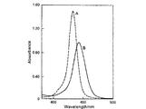
- FIG. 2 is a visible absorption spectrum diagram of TiO (tpypH 4 ) 4+ and TiO 2 (tpypH 4 ) 4+ .
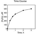
- FIG. 3 is a graph showing the quantitative results of hydrogen peroxide in Example 1.
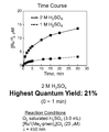
- FIG. 4 is a graph showing the quantitative results of hydrogen peroxide in Example 2.
- FIG. 5 is a schematic diagram illustrating the reaction mechanism of Reference Example 1 and a graph showing the reaction results.
- FIG. 6 is a graph showing the reaction results when the sulfuric acid concentration is changed in Reference Example 1.
- FIG. 7 is a schematic view illustrating the reaction mechanism of Reference Example 2 and a graph showing the reaction results.
- FIG. 1 is a schematic diagram showing an example of the configuration of the fuel cell of the present invention.
- FIG. 2 is a visible absorption spectrum diagram of TiO (tpypH 4 ) 4+ and TiO 2 (tpypH 4
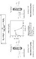
- FIG. 8 is a schematic view illustrating the reaction mechanism of Example 3 and a graph showing the reaction results.
- FIG. 9A is a schematic view illustrating the reaction mechanism of Example 4 and a graph showing the reaction results.
- FIG. 9B is another graph showing the reaction results of Example 4.
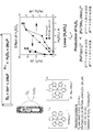
- FIG. 10A is a schematic view illustrating the reaction mechanism of Example 5, and a graph showing the reaction results of Example 5 and Reference Example 3.
- FIG. 10B is another graph showing the reaction results of Example 5.
- FIG. 10C is another graph showing the reaction results of Reference Example 3.
- FIG. 11 is an example of thermogravimetric analysis / differential thermal analysis (thermogravimetric-differential thermal analysis, TG / DTA) and dynamic light scattering (DLS) measurement results of iridium oxide.
- FIG. 12A and 12B show cyclic voltammetry of Rb 8 K 2 [ ⁇ Ru 4 O 4 (OH) 2 (H 2 O) 4 ⁇ ( ⁇ -SiW 10 O 36 ) 2 ] ⁇ 25H 2 O. It is a graph which illustrates a measurement result.
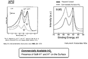
- FIG. 13 is a graph illustrating the result of X-ray photoelectron spectroscopy measurement of iridium oxide.
- FIG. 14 is another graph showing the results of the same X-ray photoelectron spectroscopy measurement as in FIG.
- FIG. 15 is a schematic diagram illustrating the reaction mechanism of Reference Example 4 and a graph showing the reaction results.
- FIG. 16 is a schematic view illustrating the reaction mechanism of Example 6 and a graph showing the reaction results.
- FIG. 17 is a schematic diagram illustrating the reaction mechanism of Example 7 and a graph showing the reaction results.
- FIG. 18 is a schematic diagram illustrating a reaction mechanism and a graph showing a reaction result for each of Reference Example 5 and Example 8.
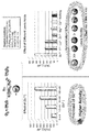
- FIG. 19 is a schematic view illustrating the reaction mechanism of Examples 9 and 10 and a graph showing the reaction results.
- FIG. 20 is a schematic view illustrating the reaction mechanism of Examples 11 and 12 and a graph showing the reaction results.
- FIG. 21 is a graph showing the reaction results of Example 13.
- FIG. 22 is another graph showing the reaction results of Example 13.
- reaction mechanism of hydrogen peroxide generation is not necessarily clear, but it is assumed as shown in the following scheme 1, for example.
- Scheme 1 and the description thereof merely represent an example of a specifiable reaction mechanism, and do not limit the present invention.
- [M 1 ] represents a transition metal atom in the transition metal complex.
- the “atom” may be an ion unless otherwise specified.
- the water oxidation catalyst Cat Oxidizes water to generate oxygen O 2 .
- the transition metal atom [M 1 ] in the transition metal complex becomes a transition metal atom [M 1 ] * in an excited state by light irradiation.
- This excited state transition metal atom [M 1 ] * reduces the dissolved oxygen gas O 2 in water to produce hydrogen peroxide H 2 O 2 and is itself oxidized to [M 1 ] + .
- the dissolved oxygen gas O 2 may be, for example, oxygen previously dissolved in water (in the reaction system), or the water oxidation catalyst Cat. May be oxygen generated by oxidizing water.
- the proton source of hydrogen peroxide H 2 O 2 is considered to be, for example, water or protons dissolved in water.
- Water oxidation catalyst Cat Although not shown, it is assumed that reversible changes are repeated between the oxidized state and the reduced state. That is, the oxidation catalyst Cat. Oxidizes water to generate oxygen O 2, which is reduced by water to a reduced state. The reduced water oxidation catalyst Cat. However, the transition metal atom [M 1 ] + is reduced to [M 1 ] and returns to the oxidation state. Thus, the transition metal complex containing the transition metal atom [M 1 ] and the water oxidation catalyst Cat. Can act as a catalyst to produce hydrogen peroxide H 2 O 2 from water H 2 O and oxygen O 2 .
- Transition metal atoms tend to have multiple states with different oxidation numbers. Further, the ligand is coordinated to the transition metal atom to form a complex, whereby the excited state of the transition metal atom is stabilized.
- the present inventors paid attention to these properties of the transition metal complex and found that it can be used in the method for producing hydrogen peroxide of the present invention by combining with a water oxidation catalyst.
- the oxidation number (charge) of [M 1 ] is not limited to 0 and is arbitrary.
- the oxidation number (charge) of [M 1 ] + is not limited to +1 as long as it is larger than the oxidation number (charge) of [M 1 ].
- the substance ratio of each reactant and product does not necessarily reflect the stoichiometric ratio.
- the scheme 1 can be represented as, for example, the following scheme 2 when the transition metal complex is a ruthenium divalent complex and the water oxidation catalyst is iridium oxide.
- the following scheme 2 is an example of a presumable reaction mechanism and does not limit the present invention.
- Ru II represents a ruthenium atom (a divalent ion) in the ruthenium divalent complex
- Ru III represents a ruthenium atom in the ruthenium trivalent complex formed by oxidation of the ruthenium divalent complex ( Trivalent ion).
- IrO x is iridium oxide.
- X is an arbitrary positive number.
- IrO x may contain only a single oxidation number of iridium, or may be a mixture of a plurality of iridium oxides having different oxidation numbers. That is, IrO x may be at least one selected from the group consisting of IrO, Ir 2 O 3 , IrO 2 , IrO 3 and IrO 4 , for example.
- the ruthenium divalent complex is not particularly limited, and examples thereof include a ruthenium divalent complex represented by the following chemical formula (2) or (4).
- the method for producing hydrogen peroxide according to the present invention can be further simplified and reduced in cost by using visible light (such as sunlight) that is easy to use as an energy source, or by reacting only with light irradiation without using a heat source. Can be done.
- visible light such as sunlight
- the reaction is completed when the combined oxidizing agent is consumed, and no further product can be obtained.
- the transition metal complex used in combination with the water oxidation catalyst has the functions of both an oxidizing agent and a reducing agent as described above, it is possible to return to the original state after completion of the reaction. . That is, not only the water oxidation catalyst but also the transition metal complex functions as a catalyst. As a result, as long as the raw water is present, theoretically, the reaction cycle can be continued infinitely to generate hydrogen peroxide. However, this is only a theory.
- the actual reaction in the method for producing hydrogen peroxide according to the present invention usually has a finite number of cycles due to deterioration of the catalyst or the like, as in a general catalytic reaction.
- the transition metal complex used in the method for producing hydrogen peroxide of the present invention is not particularly limited.
- it may be a complex in which an organic ligand is coordinated (coordinatively bonded) to a transition metal atom.
- the coordination bond is not particularly limited, and may be, for example, a covalent bond, an ionic bond, or a bond having an intermediate property between them.
- the atom coordinated (coordinated bond) to the transition metal atom is not particularly limited, and may be, for example, a carbon atom or an atom other than carbon.
- the transition metal atom is not limited to a neutral atom, but may be an ion, and its charge (oxidation number) is arbitrary.
- the transition metal complex is preferably a complex in which an aromatic ligand is coordinated to a transition metal atom.
- the metal complex is more preferably a complex represented by the following chemical formula (1).
- M 1 is a transition metal atom
- R 1 to R 24 are each independently a hydrogen atom or an arbitrary substituent
- R 4 and R 5 may be combined to form —CH ⁇ CH—, that is, R 4 and R 5 may be combined with their bonded bipyridine ring to form a phenanthroline ring.
- each H may be independently substituted with an arbitrary substituent, m is a positive integer, 0, or a negative integer.
- transition metal complex one or a plurality of transition metal atoms may be used, and when there are a plurality of transition metal atoms, they may be the same or different.
- the transition metal atom is preferably at least one selected from the group consisting of ruthenium, osmium, iron, manganese, chromium, cobalt, iridium, rhodium, and platinum.
- M 1 is preferably ruthenium, osmium, iron, manganese, chromium, cobalt, iridium, rhodium, or platinum.
- the oxidation number (charge) of each transition metal atom is not particularly limited, but is, for example, in the range of +1 to +6.
- the oxidation number (charge) is preferably +2 or +3 for ruthenium, preferably +2 to +6 for osmium, preferably +2 to +5 for iron, or manganese.
- chromium a range of +2 to +6 is preferable.
- cobalt a range of +1 to +5 is preferable.
- iridium a range of +1 to +5 is preferable.
- platinum the range of +1 to +5 is preferable, and in the case of platinum, the range of +1 to +5 is preferable.
- M 1 is particularly preferably ruthenium.
- R 1 to R 24 are each independently a hydrogen atom, alkyl group, aryl group, nitro group, halogen group, sulfonic acid group (sulfo group), amino group, alkylamino group, carboxylic acid group (carboxy group), hydroxy A group, an alkoxy group, a perfluoroalkyl group, an acyl group, an alkanoyl group, an acyloxy group, or an alkanoyloxy group.
- R 4 and R 5 together may form —CH ⁇ CH—, that is, R 4 and R 5 together with their bound bipyridine ring may form a phenanthroline ring.
- R 20 and R 21 may form a phenanthroline ring becomes bipyridine ring integral to their a bond
- R 1 to R 24 are each independently a hydrogen atom, a linear or branched alkyl group having 1 to 6 carbon atoms, phenyl group, nitro group, halogen group, sulfonic acid group (sulfo group), amino group, carbon number 1 to 6 linear or branched alkylamino group, carboxylic acid group (carboxy group), hydroxy group, alkoxy group, perfluoroalkyl group, 1 to 6 carbon straight chain or branched alkanoyl group, or 1 carbon atom More preferably, it is a 6 straight-chain or branched alkanoyloxy group.
- H in —CH ⁇ CH— each independently represents a linear or branched alkyl group having 1 to 6 carbon atoms, phenyl group, nitro group, halogen group, sulfonic acid group (sulfo group), amino group, carbon A linear or branched alkylamino group having 1 to 6 carbon atoms, a carboxylic acid group (carboxy group), a hydroxy group, an alkoxy group, a perfluoroalkyl group, a linear or branched alkanoyl group having 1 to 6 carbon atoms, or 1 carbon atom
- H in —CH ⁇ CH— each independently represents a linear or branched alkyl group having 1 to 6 carbon atoms, phenyl group, nitro group, halogen group, sulfonic acid group (sulfo group), amino group, carbon A linear or branched alkylamino group having 1 to 6 carbon atoms, a carboxylic acid group (carboxy group), a hydroxy group, an alkoxy group, a perfluoroalkyl group, a linear or branched alkanoyl group having 1 to 6 carbon atoms, or 1 carbon atom
- H in —CH ⁇ CH— each independently represents a linear or branched alkyl group having 1 to 6 carbon atoms, phenyl group, nitro group, halogen group, sulfonic acid group (sulfo group), amino group, carbon A linear or branched alkylamino group having 1 to 6 carbon atoms, a carboxylic acid group (carboxy group), a hydroxy group, an alkoxy group, a perfluoroalkyl group, a linear or branched alkanoyl group having 1 to 6 carbon atoms, or 1 carbon atom To 6 linear or branched alkanoyloxy groups.
- R 1 to R 24 may all be hydrogen atoms, for example.
- m is preferably in the range of +1 to +5, more preferably +2, +3, or +4.
- the complex represented by the chemical formula (1) is more preferably a complex represented by the following chemical formula (2) or (3).
- M 1 and m are the same as those in the chemical formula (1).
- the complex represented by the chemical formula (1) is more preferably a complex represented by the following chemical formula (4) or (5), and particularly preferably a complex represented by the following chemical formula (4).
- transition metal complex represented by the formula (1) is not limited to the above (4) and (5), and any complex may be used.
- the transition metal complex has an isomer such as a tautomer or a stereoisomer (eg, geometric isomer, conformer isomer and optical isomer), any isomer may be used in the present invention. it can.
- the salt of the transition metal complex may be an acid addition salt or a base addition salt.
- the acid forming the acid addition salt may be an inorganic acid or an organic acid
- the base forming the base addition salt may be an inorganic base or an organic base.
- the inorganic acid is not particularly limited.
- sulfuric acid, phosphoric acid, hydrofluoric acid, hydrochloric acid, hydrobromic acid, hydroiodic acid, hypofluorite, hypochlorous acid, hypobromite Hypoarousous acid, fluorinated acid, chlorous acid, bromic acid, iodic acid, fluoric acid, chloric acid, bromic acid, iodic acid, perfluoric acid, perchloric acid, perbromic acid, periodic acid, etc.
- the organic acid is not particularly limited, and examples thereof include p-toluenesulfonic acid, methanesulfonic acid, oxalic acid, p-bromobenzenesulfonic acid, carbonic acid, succinic acid, citric acid, benzoic acid, and acetic acid.
- the inorganic base is not particularly limited, and examples thereof include ammonium hydroxide, alkali metal hydroxides, alkaline earth metal hydroxides, carbonates and hydrogen carbonates, and more specifically, for example, Examples thereof include sodium hydroxide, potassium hydroxide, potassium carbonate, sodium carbonate, sodium hydrogen carbonate, potassium hydrogen carbonate, calcium hydroxide and calcium carbonate.
- the organic base is not particularly limited, and examples thereof include ethanolamine, triethylamine, and tris (hydroxymethyl) aminomethane.
- the method for producing these salts is not particularly limited, and for example, the salts can be produced by a method such as appropriately adding the above acid or base to the electron donor / acceptor linking molecule by a known method.
- the absorption band of the transition metal complex is not particularly limited, but preferably has an absorption band in the visible light region.
- an absorption band in the visible light region for example, it becomes possible to excite visible light, and sunlight can be used as an energy source. According to this, application to a solar cell etc. is also possible, for example.
- the alkyl group is not particularly limited, and examples thereof include a methyl group, an ethyl group, an n-propyl group, an isopropyl group, an n-butyl group, an isobutyl group, a sec-butyl group, and a tert-butyl group.
- Examples include pentyl group, hexyl group, heptyl group, octyl group, nonyl group, decyl group, undecyl group, dodecyl group, tridecyl group, tetradecyl group, pentadecyl group, hexadecyl group, heptadecyl group, octadecyl group, nonadecyl group, icosyl group, etc. It is done. The same applies to groups containing an alkyl group in the structure (alkylamino group, alkoxy group, etc.).
- the perfluoroalkyl group is not particularly limited, but for example, methyl group, ethyl group, n-propyl group, isopropyl group, n-butyl group, isobutyl group, sec-butyl group and tert-butyl group, pentyl group, Perfluoro derived from hexyl, heptyl, octyl, nonyl, decyl, undecyl, dodecyl, tridecyl, tetradecyl, pentadecyl, hexadecyl, heptadecyl, octadecyl, nonadecyl, icosyl, etc.
- the acyl group is not particularly limited.
- formyl group, acetyl group, propionyl group, isobutyryl group, valeryl group, isovaleryl group, pivaloyl group, hexanoyl group, cyclohexanoyl group, benzoyl group, ethoxycarbonyl The same applies to groups containing an acyl group in the structure (acyloxy group, alkanoyloxy group, etc.).
- the carbon number of the acyl group includes carbonyl carbon.
- an alkanoyl group having 1 carbon atom refers to a formyl group.
- halogen refers to any halogen element, and examples thereof include fluorine, chlorine, bromine and iodine.
- any isomer may be used.
- propyl group it may be an n-propyl group or an isopropyl group.
- the transition metal complex may be a commercially available product or may be produced (synthesized) as appropriate.
- the production method is not particularly limited, and for example, it can be suitably produced by a known production method or referring to a known production method.
- the transition metal salt and the ligand may be prepared by dissolving in a solvent such as water or alcohol and mixing them.
- the transition metal complex represented by any one of the chemical formulas (2) to (5) (particularly, the chemical formula (4) or (5)), for example, referring to the method described in the following Reference 1 It may be manufactured.
- the produced transition metal complex may be subjected to anion exchange treatment as necessary.
- the method of the anion exchange treatment is not particularly limited, and any method can be used as necessary.
- Examples of the substance that can be used for the anion exchange treatment include the various organic acids and inorganic acids, which may be used alone or in combination of two or more.
- other reactants and solvents Etc. may be appropriately used as necessary, or may not be used.
- the water oxidation catalyst is not particularly limited, but a transition metal oxide or an oxo complex is preferred.
- the oxo complex include a ruthenium oxo complex, a manganese oxo complex, and an iridium oxo complex.
- the water oxidation catalyst is, for example, selected from the group consisting of ruthenium oxo complexes, manganese oxo complexes, iridium oxo complexes, iron oxo complexes, indium oxide, ruthenium oxide, iridium oxide, tungsten oxide, and bismuth vanadate. More preferably, it is at least one of the above.
- the water oxidation catalyst is, for example, IrO, Ir 2 O 3 , IrO 2 , IrO 3 , IrO 4 , WO 3 , BiVO 4, Rb 8 K 2 [ ⁇ Ru 4 O 4 (OH) 2 (H 2 O) 4 ⁇ ( ⁇ -SiW 10 O 36 ) 2 ], Cs 10 [Ru 4 ( ⁇ -O) 4 ( ⁇ -OH) 2 (H 2 O) 4 ( ⁇ -SiW 10 O 36 ) 2 ], Li 10 [Ru 4 ( ⁇ -O) 4 ( ⁇ -OH) 2 (H 2 O) 4 ( ⁇ -SiW 10 O 36 ) 2 ], Li 10 [Ru 4 ( ⁇ -O) 4 ( ⁇ -OH) 2 (H 2 O) 4 ( ⁇ -SiW 10 O 36 ) 2 ], Na 10 [ ⁇ Ru 4 O 4 (OH) 2 (H 2 O) 4 ⁇ ( ⁇ -SiW 10 O 36 ) 2 ], K 10 [ ⁇ Ru 4 O 4 (OH) 2 (H 2 O) 4 ⁇ ( ⁇
- the water oxidation catalyst is particularly preferably iridium oxide. It is preferable that the iridium oxide be suspended in water as much as possible and that precipitation is unlikely to occur because water oxidation reaction is likely to occur during light irradiation. More specifically, the iridium oxide can be suspended at least 1 mg in 100 mL of water at 25 ° C., more preferably at least 1.5 mg, more preferably at least 3.0 mg. More preferably, at least 12 mg can be suspended, more preferably at least 50 mg can be suspended, more preferably at least 80 mg can be suspended, and at least 100 mg can be suspended. More preferably, at least 200 mg can be suspended, and at least 300 mg can be suspended.
- the iridium oxide has an average particle diameter measured by dynamic light scattering of preferably 1 to 10,000 nm, more preferably 1 to 1,000 nm, and more preferably 5 to 500 nm. More preferably, the thickness is 10 to 500 nm.
- the iridium oxide has a specific surface area measured by BET surface area measurement of preferably 0.8 m 2 / g or more, more preferably 5 m 2 / g or more, and 10 m 2 / g or more. More preferably, it is more preferably 20 m 2 / g or more.
- the upper limit of the specific surface area is not particularly limited, for example, it is 50 m 2 / g or less, or 30 m 2 / g or less.
- the weight change of the iridium oxide is preferably within 70%, and within 40% when the weight change is measured from 0 ° C. to 600 ° C. by thermogravimetric / differential thermal analysis. More preferably, it is more preferably within 30%.
- the absolute value of the potential change when measuring the potential by differential thermal analysis from 0 ° C. to 600 ° C. is preferably within 20 ⁇ V, more preferably within 10 ⁇ V, and within 5 ⁇ V. Is more preferable.
- the valence of iridium may be 0, 1, 2, 3, 4, 5, 6 or the like.
- the iridium atom in the iridium oxide may be composed of only one kind of valent iridium atom or may contain a plurality of kinds of atoms having different atomizations, but preferably contains a trivalent iridium atom.
- the iridium oxide preferably has a binding energy derived from the oxygen 1s orbital of 528 to 536 eV (electron volts), as measured by X-ray photoelectron spectroscopy, and is 530 to 534 eV. More preferably, it is more preferably 531 to 533 eV.
- the method for producing the iridium oxide is not particularly limited. For example, it can be obtained by heating H 2 IrCl 6 .6H 2 O in an aqueous NaOH solution. This manufacturing method will be described later.
- the water oxidation catalyst preferably has, for example, a property that it is easily suspended in water and hardly dissolved. This is because, if the water oxidation catalyst has such properties, it can be easily separated from the reaction system only by filtration and easy to handle.
- examples of the water oxidation catalyst that is easily suspended in water and hardly dissolved include iridium oxide, tungsten oxide, and bismuth vanadate.
- the transition metal complex may be a complex that is easily suspended in water and hardly dissolved.
- the method for producing the water oxidation catalyst is not particularly limited.
- H 2 IrCl 6 .6H 2 O may be produced by heating in an aqueous NaOH solution.
- the concentration of H 2 IrCl 6 .6H 2 O is not particularly limited, but is, for example, 1 to 300 mmol / L, preferably 10 to 80 mmol / L, more preferably 20 to 50 mmol / L.
- the concentration of NaOH is not particularly limited, but is, for example, 0.001 to 10 mmol / L, preferably 0.05 to 1 mmol / L, and more preferably 0.1 to 0.5 mmol / L.
- the heating temperature is not particularly limited, for example, it is 40 ° C. or higher, preferably 80 ° C. or higher, and it is particularly preferable to heat near the boiling point of water (about 100 ° C. at normal pressure). For example, you may reflux using a cooling pipe etc. as usual.
- the heating time is not particularly limited, but is, for example, 2 to 100 minutes, preferably 10 to 50 minutes, more preferably 20 to 40 minutes.
- iridium salts such as K 2 IrCl 6 may be used in addition to or instead of H 2 IrCl 6 .6H 2 O.
- alkali metal hydroxides such as KOH or other inorganic bases may be used in addition to or instead of NaOH.
- the method for purifying the produced iridium oxide is not particularly limited, and for example, a precipitate of iridium oxide may be collected by filtration, washed with water as necessary, and dried.
- the manufacturing method of the above iridium oxides can be performed with reference to the below-mentioned Example or the following reference document 2, for example.
- the water oxidation catalyst when it is a metal complex, it can be produced by a method of mixing a metal ion aqueous solution and a ligand aqueous solution and reacting the metal ion with the ligand. After mixing the aqueous solution, heating or the like may be performed as necessary.
- a method for producing such a water oxidation catalyst for example, Non-Patent Document 1 (YV Geletii, B. Botar, P. Koegerler, DA Hillesheim, DG Musaev, CL Hill, Angew. Chem., Int. Ed.
- Tris (2,2'-bipyridyl) perchlororuthenium (III) salt (Ru (bpy) 3 3+ ) Cl 3 oxidizes Ru (bpy) 3 2+ with PbO 2 in 0.5 MH 2 SO 4
- the solution was obtained by precipitation with addition of concentrated HClO 4 (VY Shafirovich, VV Strelets, Bulletin of the Academy of Sciences of the USSR, Division of Chemical Sciences 1980, 7. and VY Shafirovich, NK Khannanov, VV Strelets, Symposium Journal de Chimie 1980, 4, 81.).
- the resulting (Ru (bpy) 3 3+ ) Cl 3 was dried under reduced pressure, stored at ⁇ 18 ° C. in a sealed vial, and used up within 1-2 weeks.
- the precipitate was collected by filtration and washed with 1M KCl aqueous solution to obtain the target product K 8 [ ⁇ -SiW 10 O 36 ] ⁇ 12H 2 O ( ⁇ 10 g) (yield 70%).
- the pH was measured (tracked) using a pH meter as appropriate.
- Elemental analysis value Calculated value: W 55.14, Ru 6.11, Si 0.84, Rb 10.18, K 1.17; Measured value: W 55.2, Ru 5.8, Si 0.73, Rb 10.2, K 0.95. It was measured by gravimetric analysis (thermogravimetricanalysis, TGA).
- IR (KBr pellet; 2000-400cm -1 ): 1616 (m), 999 (m), 947 (ms), 914 (s), 874 (s), 802 (vs), 765 (vs), 690 (sh ), 630 (sh), 572 (ms), 542 (ms).
- FIGS. 12A and 12B the Rb 8 K 2 [ ⁇ Ru 4 O 4 (OH) 2 (H 2 O) 4 ⁇ ( ⁇ -SiW 10 O 36 ) 2 ] ⁇ 25H 2 O
- the measurement result of click voltammetry (CV) is shown.
- the horizontal axis represents voltage (mV) and the vertical axis represents current.
- the measurements in FIGS. 12 (a) and 12 (b) were both performed at a scan rate of 25 mV / s with respect to a pH 7.0 solution of 0.025M sodium phosphate buffer and 0.15M NaCl.
- FIG. 12 (a) and 12 (b) were both performed at a scan rate of 25 mV / s with respect to a pH 7.0 solution of 0.025M sodium phosphate buffer and 0.15M NaCl.
- the solid line represents the pH of 0.6 mM Rb 8 K 2 [ ⁇ Ru 4 O 4 (OH) 2 (H 2 O) 4 ⁇ ( ⁇ -SiW 10 O 36 ) 2 ] ⁇ 25H 2 O.
- the dashed line represents 1 mM Rb 8 K 2 [ ⁇ Ru 4 O 4 (OH) 2 (H 2 O) 4 ⁇ ( ⁇ -SiW 10 O 36 ) 2 ] ⁇ 25H 2 O in 0.1 M HCl (pH 1.0). It is a measured value.
- Dotted line shows 1 mM Rb 8 K 2 [ ⁇ Ru 4 O 4 (OH) 2 (H 2 O) 4 ⁇ ( ⁇ -SiW 10 O 36 ) 2 ] ⁇ 25H 2 O in 0.4 M difference sodium acetate buffer ( The measured value at pH 4.7). The voltage is a value relative to an Ag / AgCl reference electrode (3m NaCl). As shown in the figure, the CV of Rb 8 K 2 [ ⁇ Ru 4 O 4 (OH) 2 (H 2 O) 4 ⁇ ( ⁇ -SiW 10 O 36 ) 2 ] ⁇ 25H 2 O was pH-dependent. In FIG.
- the solid line represents Rb 8 K 2 [ ⁇ Ru 4 O 4 (OH) 2 (H 2 O) 4 ⁇ ( ⁇ -SiW 10 ) in the presence of 1 mM [Ru (bpy) 3 ] 2+. It is a measurement result without O 36 ) 2 ] ⁇ 25H 2 O (concentration 0).
- the broken line represents Rb 8 K 2 [ ⁇ Ru 4 O 4 (OH) 2 (H 2 O) 4 ⁇ ( ⁇ -SiW 10 O 36 ) 2 ] ⁇ 25H in the presence of 1 mM [Ru (bpy) 3 ] 2+ It is a measurement result at 2 O concentration 0.006 mM.
- the dash-dot line is Rb 8 K 2 [ ⁇ Ru 4 O 4 (OH) 2 (H 2 O) 4 ⁇ ( ⁇ -SiW 10 O 36 ) 2 ] ⁇ in the presence of 1 mM [Ru (bpy) 3 ] 2+ This is a measurement result at a 25H 2 O concentration of 0.012 mM.
- the dotted line is Rb 8 K 2 [ ⁇ Ru 4 O 4 (OH) 2 (H 2 O) 4 ⁇ ( ⁇ -SiW 10 O 36 ) 2 ] ⁇ 25H in the presence of 1 mM [Ru (bpy) 3 ] 2+ It is a measurement result at 2 O concentration 0.029 mM.
- the two-dot chain line indicates that Rb 8 K 2 [ ⁇ Ru 4 O 4 (OH) 2 (H 2 O) 4 ⁇ ( ⁇ -SiW 10 O 36 ) 2 ] in the absence of [Ru (bpy) 3 ] 2+ ⁇ Measurement results at 25H 2 O concentration of 0.029 mM. All measurements in FIG. 12B were performed at pH 7.0.
- the resulting dark brown solution had a pH of 6.2.
- the solution was heated at 70 ° C. for 1 hour and filtered when the pH reached 1.8. Further, an excessive amount of CsCl (4.4 g, 26.1 mmol) was added to the filtrate to obtain a precipitate. This precipitate was washed three times with 2-3 mL of cold water, and the target cesium salt Cs 10 [Ru 4 ( ⁇ -O) 4 ( ⁇ -OH) 2 (H 2 O) 4 ( ⁇ -SiW 10 O 36] ) 2 ] was obtained 980 mg (85%).
- the aqueous solution of the unpurified lithium salt was purified by passing through a column with Sephadex (trade name) G-50 as a stationary phase and discarding the first about 50 mg fraction.
- the amount of water and the stationary phase was set to a ratio of 5 mL of water to 10 g of the lithium salt and 10 g of the stationary phase.
- the solvent was distilled off from the eluate to obtain 700 mg of purified lithium salt (75% yield based on W). It should be noted that the stationary phase of the column remained black even after the total elution of the target product, which is presumed to be because some low molecular weight ruthenium species remained.
- Cesium salt Cs 10 [Ru 4 ( ⁇ -O) 4 ( ⁇ -OH) 2 (H 2 O) 4 ( ⁇ -SiW 10 O 36 ) 2 ] Elemental analysis of crystals (in parentheses are Cs 10 [Ru 4 ( ⁇ -O) 4 ( ⁇ -OH) 2 (H2O) 4 ( ⁇ -SiW 10 O 36 ) 2 ])): Cs: 19.20% (19.58%); Ru: 5.93% (5.96%); Si: 0.845% (0.827%); W: 53.75% (54.16%). When the sample was dried before elemental analysis, the mass decreased by 3.85%. This corresponds to 15 molecules of hydration water for Cs 10 [Ru 4 ( ⁇ -O) 4 ( ⁇ -OH) 2 (H 2 O) 4 ( ⁇ -SiW 10 O 36 ) 2 ].
- the method for producing hydrogen peroxide of the present invention generates hydrogen peroxide by generating light by irradiating light to a reaction system containing water, a water oxidation catalyst, a transition metal complex, and oxygen (O 2 ). Including a process.
- the method for producing hydrogen peroxide of the present invention is not particularly limited, but can be carried out, for example, as follows.
- the reaction system containing water, a water oxidation catalyst, a transition metal complex, and oxygen (O 2 ) is prepared.
- This reaction system preparation step may be performed, for example, prior to the hydrogen peroxide generation step, or part or all of the reaction system preparation step is performed simultaneously with the hydrogen peroxide generation step (that is, while irradiating the reaction system with light). It can also be done.
- each of a water oxidation catalyst, a transition metal complex, and oxygen (O 2 ) may be dispersed in water.
- the form of the dispersion is not particularly limited, and may be, for example, dissolved or suspended.
- the concentration of the transition metal complex is not particularly limited, and is, for example, 0.0001 to 0.1 mmol / L, preferably 0.002 to 0.05 mmol / L, particularly preferably 0.004 to 0.02 mmol / L.
- the concentration of the water oxidation catalyst is not particularly limited, but is, for example, 0.05 to 10 g / L, preferably 0.5 to 5 g / L, and more preferably 0.8 to 2 g / L.
- the concentration of oxygen (O 2 ) is not particularly limited, but is preferably as high as possible from the viewpoint of reactivity, and it is particularly preferable to saturate the reaction system (in water) with oxygen (O 2 ).
- the reaction system may or may not contain substances other than water, a water oxidation catalyst, a transition metal complex, and oxygen (O 2 ).
- the reaction system may further include, for example, a pH adjuster from the viewpoint of reactivity described later.
- the pH adjuster include basic substances such as sodium hydroxide, potassium hydroxide, sodium hydrogen phosphate, potassium hydrogen phosphate, sodium phosphate, potassium phosphate, sodium acetate, hydrochloric acid, sulfuric acid, nitric acid, acetic acid. And acidic substances such as phosphoric acid.
- the water may be in a state where a pH buffer solution is dissolved to form a pH buffer solution.
- the pH buffer solution examples include a phosphate buffer aqueous solution and an acetate buffer aqueous solution.
- the addition amount of the pH adjusting agent and the pH buffering agent is not particularly limited and can be set as appropriate. Although depending on other reaction conditions, the reduction of oxygen often has better reaction efficiency under acidic conditions, and the oxidation of water often has better reaction efficiency under basic conditions. Therefore, in consideration of these, it is preferable to appropriately set the pH of the reaction system so that the production efficiency of hydrogen peroxide is improved. From this viewpoint, the pH of the reaction system is, for example, ⁇ 2 to 10, preferably ⁇ 2 to 8, more preferably ⁇ 2 to 7, further preferably ⁇ 1 to 5, further preferably ⁇ 0.5 to 3, and further preferably.
- the pH of the reaction system is preferably -2 to 8, more preferably -2 to 5, and still more preferably -1 to 3. Particularly preferred is -0.5 to 2.
- the reaction system may further contain a Lewis acid from the viewpoint of production efficiency of hydrogen peroxide.
- the Lewis acid is preferably a metal ion, more preferably a transition metal ion, and even more preferably a Group 3 metal ion.
- the group 3 metal ions include scandium ions, yttrium ions, lanthanoid ions, and actinoid ions.
- the content (number of moles) of the metal ion is not particularly limited, but for example, 1 to 50000 times the amount (number of moles) of the transition metal complex
- the ratio is preferably 100 to 10,000 times, more preferably 1000 to 10,000 times.
- the said Lewis acid (for example, the said metal ion) or its salt may serve as the said pH adjuster.
- the reaction system may further contain an organic solvent or may not contain an organic solvent.
- organic solvent include nitriles such as benzonitrile, acetonitrile, and butyronitrile, halogenated solvents such as chloroform and dichloromethane, ethers such as THF (tetrahydrofuran), amides such as DMF (dimethylformamide), DMSO (dimethylsulfoxide), and the like. Sulfoxides, ketones such as acetone, alcohols such as methanol, nitromethane and the like. These solvents may be used alone or in combination of two or more.
- the solvent is preferably a highly polar solvent, particularly acetonitrile, from the viewpoint of the solubility of the transition metal complex, the stability of the excited state, and the like.
- a hydrogen peroxide generation step is performed in which the reaction system containing water, a water oxidation catalyst, a transition metal complex, and oxygen (O 2 ) is irradiated with light to generate hydrogen peroxide.
- the hydrogen peroxide generation step can be performed simultaneously with the reaction system preparation step, or can be performed after the reaction system preparation step.
- water is irradiated with oxygen (O 2) while irradiating light to a system including a water oxidation catalyst and a transition metal complex. ) May be dissolved.
- Irradiation light for light irradiation is not particularly limited, but visible light is preferable.
- the transition metal complex In order to excite the transition metal complex with visible light, the transition metal complex preferably has an absorption band in the visible light region.
- the wavelength of visible light to be irradiated depends on the absorption band of the transition metal complex, but is, for example, 400 to 850 nm, more preferably 410 to 750 nm, and further preferably 420 to 650 nm.
- the wavelength of the irradiation light is, for example, as described above, and particularly preferably 420 to 550 nm.
- the temperature at the time of light irradiation is not particularly limited, but may be a room temperature of about 10 to 30 ° C., for example.
- the light source is not particularly limited.
- natural light such as sunlight from the viewpoint of energy saving.
- sunlight contains light in a wide wavelength region (particularly in the visible light region) and is excellent in light intensity, it is easy to obtain high reaction efficiency.
- a light source such as a xenon lamp, a halogen lamp, a fluorescent lamp, or a mercury lamp may or may not be used as appropriate.
- a filter that cuts wavelengths other than the necessary wavelength may or may not be used as appropriate.
- the reaction system may be left as it is, but may be irradiated with stirring. If necessary, the reaction system may be heated or the like, but it is preferable that the reaction is performed simply by light irradiation without heating or the like.
- the light irradiation time, light intensity, and the like are not particularly limited and can be set as appropriate.
- the reaction mechanism in the hydrogen peroxide generation step can be represented by, for example, the scheme 1 or 2.
- the oxygen molecule O 2 that is a raw material for hydrogen peroxide is not particularly limited, and may be, for example, O 2 generated by oxidation of water or dissolved in water before the reaction. O 2 may be used, or O 2 in the atmosphere may be dissolved in water while stirring the reaction system. As described above, it is particularly preferable from the viewpoint of reaction efficiency that the reaction system (in water) is saturated with O 2 in advance.
- TON turnover number
- TOF Total Over Frequency, the number of rotations of the catalyst per hour
- the TON is the number of moles of hydrogen peroxide generated per mole of the catalyst in the entire hydrogen peroxide generation step
- the TOF is calculated by dividing the TON by the time (h) of the hydrogen peroxide generation step. This is the calculated value.
- the TON and TOF can be defined for each.
- the TON based on the transition metal complex is, for example, 1 or more, preferably 10 or more, more preferably 100 or more, and the upper limit is not particularly limited, but is, for example, 10,000 or less.
- the TOF based on the transition metal complex is, for example, 5 or more, preferably 10 or more, more preferably 50 or more, and the upper limit is not particularly limited, but is, for example, 5,000 or less.
- the hydrogen peroxide production method of the present invention can be performed as described above. Furthermore, the hydrogen peroxide production method of the present invention may further include a hydrogen peroxide purification step for purifying the generated hydrogen peroxide after the hydrogen peroxide generation step, if necessary. Thereby, high-purity hydrogen peroxide or hydrogen peroxide water suitable for practical use can be obtained. Although it does not restrict
- the kit for producing hydrogen peroxide according to the present invention includes the transition metal complex used in the method for producing hydrogen peroxide according to the present invention and the water oxidation catalyst.
- the kit for producing hydrogen peroxide of the present invention can be used for a wide range of uses such as laboratory use and industrial use by devising the configuration, scale and the like.
- the fuel cell of the present invention is a fuel cell including a fuel container and a fuel cell, and the transition metal complex used in the method for producing hydrogen peroxide of the present invention in the fuel container, And an oxidation catalyst for the water.
- the fuel cell of the present invention is not particularly limited. For example, it is as follows.
- the fuel battery cell is not particularly limited, and may have a structure including an anode and a cathode, for example.
- the fuel battery cell may be integrated with the fuel container, for example.
- the reaction on the anode side can be expressed by, for example, the following formula [1].
- the reaction on the cathode side can be expressed by, for example, the following formula [2].
- the total reaction combining these can be expressed, for example, by the following mathematical formula [3].
- the fuel cell of the present invention may be constructed with reference to the following reference 3 or 4, for example.
- FIG. 1 schematically shows an example of the configuration of the fuel cell of the present invention.
- this fuel cell includes an acidic solution in a fuel container that also serves as a fuel cell.
- the acidic aqueous solution is an aqueous solution in which oxygen (O 2 ) is dissolved and the pH is adjusted to be acidic.
- oxygen (O 2 ) oxygen
- the oxidation catalyst for water and the transition metal complex are dispersed (dissolved or suspended) in the acidic aqueous solution.
- an anode made of nickel (Ni) and a cathode made of glassy carbon (glass-like carbon, GC) are immersed.
- the cathode and the anode are connected by a conducting wire outside the acidic aqueous solution, and electrons (e ⁇ ) can move in the conducting wire from the anode toward the cathode.
- the cathode is selected from the group consisting of porphyrin complexes [Fe (OEP) Cl], [Fe (TPP) Cl] and [Fe (Pc) Cl] represented by the following chemical formulas (a) to (c): At least one type is fixed.
- the following chemical formulas (a) to (c) all represent the structure of Fe (III), that is, a trivalent iron complex. A substituted structure may be used.
- the reaction of the formula [1] occurs on the anode side
- the reaction of the formula [2] occurs on the cathode side.
- a basic aqueous solution or a neutral aqueous solution may be used instead of the acidic aqueous solution, and the composition of the aqueous solution may be changed as appropriate.
- the material of the anode and the cathode is not particularly limited, and can be changed as appropriate.
- the fuel cell of the present invention may be constructed with reference to the following, for example, but is not limited thereto.
- the electrode modified with the Fe complex was immersed in 10 ⁇ L of Nafion (trade name) solution (MeOH, 0.05%) and dried in a dryer at 70 ° C. for 40 minutes to coat with Nafion.
- the amount of the Fe complex fixed on the glassy carbon electrode was calculated based on the FeIII / FeII reduction current in a solution not containing H 2 O 2 .
- the charges for the reduction of [Fe (TPP) Cl], [Fe (OEP) Cl] and [Fe (Pc) Cl] are 3.6 ⁇ 10 ⁇ 7 , 7.6 ⁇ 10 ⁇ 7 and 2.9 ⁇ 10 ⁇ 6, respectively. C. These charges correspond to 3.7 ⁇ 10 ⁇ 12 , 7.9 ⁇ 10 ⁇ 12 and 3.0 ⁇ 10 ⁇ 11 mol of the respective complexes.
- reaction mechanism described in the drawings or the description thereof is an example of a mechanism that can be estimated, and does not limit the present invention.
- the absorbance (ultraviolet-visible absorption spectrum) of the solution was measured using a device 8453 photodiode array spectrophotometer (trade name) manufactured by Hewlett-Packard.
- the ultraviolet-visible absorption spectrum by diffuse reflection spectroscopy was measured using Shimadzu UV-3300PC (trade name) manufactured by Shimadzu Corporation and ISR-3100 (trade name) of the company as an accessory device.
- Voltammetry (cyclic voltammetry, CV) was measured using a device ALS630B electrochemical analyzer (trade name) manufactured by BAS.
- Zeta Sizer Nano ZS (trade name) of Malvern Instruments Ltd. of the United States was used for dynamic light scattering (Dynamic Light Scattering: DLS) measurement.
- the DLS measurable range with this instrument is 0.6-6000nm.
- Thermogravimetric-differential thermal analysis (thermogravimetric analysis / differential thermal analysis, TG / DTA) was performed using TG / DTA 7200 (trade name) manufactured by SII.
- X-ray photoelectron spectroscopy measurements were performed using AXIS-165 (trade name) manufactured by Kratos.
- BET surface area measurement was performed using Bel Japan Belsorp II mini (trade name).
- Ushio Optical ModelX SX-UID 500XAMQ (trade name, wavelength ⁇ > 390 nm, output 500 W) manufactured by USHIO INC. Was used.
- Shimadzu fluorescence spectrophotometer RF-5300PC (trade name) manufactured by Shimadzu Corporation was used. All chemical substances were reagent grade and were purchased from Tokyo Chemical Industry Co., Ltd., Wako Pure Chemical Industries, Ltd., Aldrich, or Nacalai Tesque Co., Ltd. unless otherwise specified.
- TiO (tpypH 4 ) 4+ represented by the chemical formula described in Scheme 3 below. That is, when TiO (tpypH 4 ) 4+ dissolved in HCl aqueous solution (referred to as Ti-TPyP reagent) is mixed with an aqueous solution in which hydrogen peroxide is dissolved after the completion of the reaction, TiO (tpypH 4 ) is as follows: 4+ reacts with hydrogen peroxide to become TiO 2 (tpypH 4 ) 4+ .
- the graph of FIG. 2 shows visible absorption spectra of TiO (tpypH 4 ) 4+ and TiO 2 (tpypH 4 ) 4+ .
- the horizontal axis represents wavelength (nm), and the vertical axis represents absorbance.
- the curve represented by the broken line (A) is the absorption spectrum of TiO (tpypH 4 ) 4+ (Ti-TPyP reagent), and the curve represented by the solid line (B) is the TiO 2 (tpypH 4 ) 4+ Represents an absorption spectrum.
- the maximum absorption wavelength of TiO 2 (tpypH 4 ) 4+ is shifted to the longer wavelength side. 2 is shown in FIG.
- Iridium oxide water oxidation catalyst
- Iridium oxide water oxidation catalyst
- H 2 IrCl 6 .6H 2 O 1 g
- Aqueous NaOH (5M) was added to adjust the pH value to 10
- the mixture was heated to 100 ° C. for 30 minutes in an oil bath. This was left at room temperature and filtered to obtain a solid. This was dried at room temperature using a vacuum pump, and further dried in air at 65 ° C. for 12 hours to obtain IrO x .
- IrO x is an unknown (unconfirmed) number.
- this self-prepared IrO x is represented. 1 to 22 may be described as “Ir (OH) 3 ”, but this notation is synonymous with the above IrO x .
- the reason why the notation “Ir (OH) 3 ” is used is that, as shown in Reference Example 3 described later, it was estimated by XPS measurement that a large amount of Ir (OH) 3 was present on the IrO x surface. However, this notation is a notation for convenience and does not limit the structure of IrO x .
- Example 1 Production of hydrogen peroxide
- Ti-TPyP reagent was prepared by adding TiO (tpypH 4 ) 4+ (50 ⁇ M) to an aqueous HCl solution (50 mM).
- reaction solution aqueous HCl solution
- 0.25 mL of HClO 4 (4.8M) and 0.25 mL of Ti-TPyP reagent were added to 0.25 mL of this solution and allowed to stand for 5 minutes.
- the solution after standing was diluted to 2.5 mL with water, the visible absorption spectrum was measured, and hydrogen peroxide was quantified. Since the degree of ionization of dilute sulfuric acid is almost 100%, for example, the pH of an aqueous solution having a sulfuric acid H 2 SO 4 concentration of 2M can be estimated to be about ⁇ 0.60 (minus 0.60). .
- the ruthenium divalent complex [Ru II (Me 2 -phen) 3 ] Cl 2 was synthesized by the method described in Reference Document 7 below. Specifically, first, a mixed solvent of ethanol (16 mL) and deionized purified water (4 mL) was mixed with ruthenium (III) chloride (Ruthenium (III) trichloride, RuCl 3 ) (82.97 mg, 0.4 mmol) and 4,7 -Dimethyl-1,10-phenanthroline (4,7-Dimethyl-1,10-phenanthroline) (499.82 mg, 2.4 mmol) was added, and the resulting orange was heated to reflux at 100 ° C. for 48 hours under a nitrogen atmosphere.
- ruthenium (III) chloride Ruthenium (III) trichloride, RuCl 3
- the graph of FIG. 3 shows the result of quantitative determination of hydrogen peroxide in Example 1 above.
- the horizontal axis represents the reaction time, that is, the light irradiation time (h)
- the vertical axis represents the hydrogen peroxide concentration ( ⁇ M) in the reaction system (reaction solution).
- TON based on [Ru II (Me 2 -phen) 3 ] Cl 2
- the present invention is the first production method capable of producing hydrogen peroxide with high efficiency using oxygen and water as raw materials.
- Example 2 Add [Ru II (Me 2 -phen) 3 ] Cl 2 (20 ⁇ M) and IrO x (3.0 mg) to H 2 SO 4 aqueous solution (2 M, 3.0 mL), add a stirrer bar, and then use a rubber septum. Then, it was sealed in a two-sided cell having an optical path length of 1 cm, and oxygen gas replacement was performed. This was reacted with a slit width of 5 using a SHIMADZU fluorescence spectrophotometer RF-5300PC (trade name) manufactured by Shimadzu Corporation. Quantification of hydrogen peroxide after the reaction was performed using TiO (tpypH 4 ) 4+ . The light intensity at this time was 1.1 ⁇ 10 ⁇ 9 einstein s ⁇ 1 .
- the graph of FIG. 4 shows the result of quantitative determination of hydrogen peroxide in Example 2 above.
- the horizontal axis represents the reaction time, that is, the light irradiation time (h)
- the vertical axis represents the hydrogen peroxide concentration ( ⁇ M) in the reaction system (reaction solution).
- TON based on [Ru II (Me 2 -phen) 3 ] Cl 2
- a quantum yield of about 20% was obtained in 0 to 1 hour after the start of the reaction. Met.
- the quantum yield of photosynthesis in nature is about 1% at most, it can be said that the value of the quantum yield of about 20% is a very high value.
- oxygen (O 2 ) is generated by the oxidation of water as in the above scheme 1 or 2. Therefore, in this part, the photosynthesis and the reaction mechanism are the same. It is believed that there is.
- the present invention is not limited by the schemes 1 and 2.
- Example 1 The reaction was conducted in the same manner as in Example 2 except that no water oxidation catalyst was added to the reaction system. Further, the reaction was carried out in the same manner as described above except that oxygen (O 2 ) was not present in the system (deoxygenation was performed by replacing with argon).
- FIG. 5 shows the results.
- the lower graph of the figure is a fluorescence spectrum diagram of the aqueous solution after completion of the reaction, the horizontal axis represents the wavelength (nm), and the vertical axis represents the fluorescence intensity (relative value).
- the solid line is the fluorescence spectrum after light irradiation without the presence of oxygen (O 2 )
- the broken line is the fluorescence spectrum after light irradiation in the presence of oxygen (O 2 ).
- the upper scheme in the figure is a presumed reaction mechanism in the presence of oxygen (O 2 ). As shown in the graph, after irradiating oxygen without oxygen (O 2 ), a fluorescence spectrum based on [Ru II (Me 2 -phen) 3 ] 2+ was shown, but oxygen (O 2 ) After light irradiation in the presence of, the fluorescence almost disappeared.
- the quantum yield was confirmed by changing the concentration of sulfuric acid H 2 SO 4 to a sulfuric acid concentration of 2M (same as in Example 2) or 1M.
- the result is shown in the graph of FIG.
- the horizontal axis represents the reaction time, that is, the light irradiation time (minutes).
- the vertical axis represents the concentration ( ⁇ M) of [Ru III (Me 2 -phen) 3 ] 3+ in the reaction system (reaction solution) calculated from the fluorescence spectrum.
- the concentration of [Ru III (Me 2 -phen) 3 ] 3+ after the reaction was higher, indicating that the reaction efficiency was higher.
- the quantum yield at a sulfuric acid concentration of 2M was 21% (0 to 1 minute after the start of the reaction), which was in good agreement with the result of Example 2.
- the vertical axis represents the concentration of ruthenium trivalent complex ( ⁇ M) or the concentration of hydrogen peroxide H 2 O 2 ( ⁇ M).
- ⁇ M concentration of ruthenium trivalent complex
- H 2 O 2 concentration of hydrogen peroxide H 2 O 2
- Example 3 As a transition metal complex, [Ru II (Me 2 -phen) 3 ] Cl 2 (salt of ruthenium complex represented by the above chemical formula (4), same as Example 1) or [Ru II (bpy) 3 ] Cl 2 (The salt of the ruthenium complex represented by the chemical formula (5)), adjusting the concentration of sulfuric acid H 2 SO 4 to bring the pH of the reaction system to 0, and the amount of IrO x used is 1.
- the reaction was conducted in the same manner as in Example 1 except that the amount was 5 mg, with a light irradiation time (reaction time) of 3 hours.
- FIG. 8 shows the result.
- the horizontal axis represents the type of transition metal complex (the chemical formula (4) or (5)), and the vertical axis represents the excess in the reaction system (in water) after reacting for 3 hours. Represents the concentration ( ⁇ M) of hydrogen oxide H 2 O 2 . As shown in the figure, hydrogen peroxide H 2 O 2 could be efficiently obtained by using any transition metal complex.
- Example 4 The reaction was performed in a light irradiation time (reaction time) of 30 minutes in the same manner as in Example 1 except that the concentration of sulfuric acid H 2 SO 4 was variously changed and the amount of IrO x used was 1.5 mg.
- the result is shown in FIG. 9A.
- the horizontal axis represents the concentration (M) of sulfuric acid H 2 SO 4 in the reaction system (in water), and the vertical axis represents the concentration ( ⁇ M) of hydrogen peroxide H 2 O 2 after the reaction.
- Example 5 The reaction was carried out in the same manner as in Example 1 except that the amount of IrO x used was varied, with a light irradiation time (reaction time) of 30 minutes. The results are shown in the graph on the left side of FIG. 10A.
- the horizontal axis represents the amount of IrO x used (mg)
- the vertical axis represents the concentration ( ⁇ M) of hydrogen peroxide H 2 O 2 after the reaction.
- the concentration of hydrogen peroxide H 2 O 2 after the reaction was the highest (ie, the amount produced was large).
- reaction time light irradiation time (reaction time) into 1 hour
- the horizontal axis represents the amount of IrO x used (mg)
- the vertical axis represents the concentration ( ⁇ M) of hydrogen peroxide H 2 O 2 after the reaction.
- the concentration of hydrogen peroxide H 2 O 2 after the reaction is the most when the amount of IrO x used is 3 mg, as in the case of the reaction time of 30 minutes (the graph on the left side of FIG. 10A). It was high (ie, the amount produced was large).
- reaction time 3 mg
- IrO x or commercially available iridium (IV) oxide 3 mg
- IrO 2 purity 99% m, manufacturer: STREM CHEMICALS
- the results are shown in the graph on the right side of FIG. 10A.
- the horizontal axis represents the case where either IrO x or commercially available IrO 2 was used, and the vertical axis represents the concentration ( ⁇ M) of hydrogen peroxide H 2 O 2 after the reaction.
- the horizontal axis represents the case where either IrO x or commercially available IrO 2 was used, and the vertical axis represents the concentration ( ⁇ M) of hydrogen peroxide H 2 O 2 after the reaction.
- ⁇ M concentration of hydrogen peroxide H 2 O 2 after the reaction.
- hydrogen peroxide H 2 O 2 can be obtained efficiently when IrO x is used even when the reaction time is 1 hour, and almost all peroxides are obtained when the commercially available IrO 2 is used.
- Hydrogen H 2 O 2 was not obtained.
- the reason for the difference in the amount of hydrogen peroxide H 2 O 2 generated between IrO x and commercially available IrO 2 is not clear, but there is a hydroxyl group (OH) on the surface of IrO x. May promote water dispersibility or IrO x reactivity itself.
- the BET surface area measurement by measurement of the specific surface area of the commercial IrO 2, was 0.8 m 2 / g.
- the specific surface area of IrO x was measured in the same manner, it was 22.1 m 2 / g, which was about 28 times that of IrO 2 .
- the graph of FIG. 11 shows the thermogravimetric / differential thermal analysis (thermal gravimetric-differential thermal analysis, TG / DTA) and dynamic light scattering (DLS) of IrO x and the commercially available IrO 2.
- a measurement result is shown.
- the four graphs (upper left, upper right, lower left and lower right), the two on the left are the measurement results of the commercially available IrO 2 , and the two on the right are the measurement results of IrO x .
- the upper two represent the measurement results of thermogravimetric-differential thermal analysis (TG / DTA), and the lower two represent the measurement results of dynamic light scattering (DLS).
- the horizontal axis is temperature (° C.), and the vertical axis is the weight of the measurement sample (indicated as Weight loss in the figure) or suggested thermal analysis (measured potential ( ⁇ V) by DTA) Weighth loss is expressed as a percentage where the weight of the measurement sample before the start of measurement is 100%, and in the lower two graphs, the horizontal axis represents the particle diameter (nm) of the measurement sample.
- the vertical axis represents strength (relative value) .
- Thermogravimetric-differential thermal simultaneous analysis uses TG / DTA 7200 manufactured by SII, and samples (approximately 3 mg) from 25 ° C to 600 ° C.
- the sample was heated at a rate of 2 ° C./min until 100 ° C. and held for 10 min. ⁇ -Al 2 O 3 was used as a reference material for DTA measurement.
- DLS DLS measurement was performed using Zeta Sizer Nano ZS (trade name) of Malvern Instruments Ltd., USA, as described above. The range is 0.6-6000 nm, and the DLS measurement was performed by suspending the commercially available IrO 2 (0.1 mg) or self-prepared IrO x (0.1 mg) in distilled water (1.5 mL).
- weight loss IrO x is larger than the IrO 2 of the commercial, IrO x as compared to the commercial IrO 2 is considered to contain a lot of moisture. From DTA, this process is an endothermic process and is consistent with the dehydration process.
- the measured value of the particle diameter was larger in IrO x than in the commercially available IrO 2 .
- the commercially available IrO 2 includes those having a considerably large particle size, but when left standing, it does not disperse and precipitates, so at the time of DLS measurement, only a small amount of particles dispersed in the supernatant is formed. It is considered that the particle diameter is being measured.
- IrO x was highly dispersed in water and did not precipitate even when allowed to stand. As shown in the figure, the IrO x particle size was uniform at about 220 nm. Further, as shown in each of the above Examples, this IrO x had a high catalytic activity as a water oxidation catalyst.
- FIG. 13 also shows XPS measurement results of IrO x and the commercially available IrO 2 .
- the graph on the right side of FIG. 13 is a graph showing the XPS measurement results.
- the reference diagram on the left side of FIG. 13 is a graph showing XPS measurement results of iridium oxide in Hara, M. and co-workers. Electrochim. Acta 1983, 28, 1073.
- the horizontal axis represents the binding energy (eV, electron volt) derived from the Ir (4f) orbit
- the vertical axis represents the peak intensity (relative value).
- the dotted line represents the peak curve derived from Ir 3+
- the broken line represents the peak curve derived from Ir 4+
- the solid line represents the overlapping of the two peak curves.
- both Ir 4+ and Ir 3+ have two large peaks.
- the dotted, right-hand peak (approximately 62.0 eV) is derived from Ir 3+ .
- the dashed, right-hand peak (approximately 63.7 eV) is derived from Ir 4+ .
- the Ir 3+ curve is characterized by the larger right peak than the left peak. .
- the solid line represents the XPS measurement result of IrO x
- the broken line represents the XPS measurement result of the commercially available IrO 2 .
- the peak curves of IrO x and the commercially available IrO 2 both show a superposition of the peak curve derived from Ir 3+ and the peak curve derived from Ir 4+. It was.
- the peak on the right side is larger than the peak on the left side, so that it was confirmed that the content of Ir 3+ was high in the measured iridium atom. That is, most of the iridium atoms on the surface of IrO x are Ir 3+ , and Ir 4+ is considered to be small.
- FIG. 14 shows the same XPS measurement result as FIG.
- the graph on the upper side of FIG. 14 is the same as the graph on the right side of FIG. 13 and shows the binding energy derived from the Ir (4f) orbit.
- the lower graph of FIG. 14 shows the binding energy derived from the O (1s) orbit of the same XPS measurement.
- the horizontal axis represents binding energy (eV, electron volt)
- the vertical axis represents peak intensity (relative value).
- the peak of oxygen (1 s) was shifted with higher energy in IrO x (solid line) than in the commercially available IrO 2 (broken line).
- a reaction system including water, a water oxidation catalyst (IrO x ), and a transition metal complex ([Ru III (Me 2 -phen) 3 ] 3+ ) serving as an oxidant is prepared.
- the amount of oxygen produced with the progress was quantified.
- the above-mentioned [Ru III (Me 2 -phen) 3 ] 3+ aqueous solution (0.5 mM H 2 SO 4 acidic aqueous solution, pH 0, 12 mL) was adjusted by the method described below.
- FIG. 15 is a schematic diagram for estimating the mechanism of the reaction that occurred in Reference Example 4.
- Reference Example 4 the generation of hydrogen peroxide was not confirmed, and only the generation of oxygen (O 2 ) by the water oxidation catalyst was confirmed.
- the results are shown in the graph on the right side of FIG.
- the horizontal axis represents the reaction time (h), and the vertical axis represents the oxygen concentration ( ⁇ M) in the reaction system (reaction solution).
- the amount of oxygen (O 2 ) generated reached about 0.8 ⁇ mol in the reaction for 3 to 4 hours, and the oxygen (O 2 ) yield calculated based on the measurement with the oxygen sensor was 53%. It was.
- Example 6 Except for adding 0.1 M of scandium (III) nitrate (Sc (NO 3 ) 3 ) to the reaction system in a two-sided cell with an optical path length of 1 cm, the same procedure as in Example 1 was performed, and the wavelength exceeded 420 nm (wavelength ⁇ > (420 nm) The reaction was performed by irradiation with only light. The result is shown in the upper right graph of FIG. In the figure, the horizontal axis represents the reaction time (h), and the vertical axis represents the hydrogen peroxide concentration ( ⁇ M) in the reaction system (reaction solution). As in Example 1, hydrogen peroxide was quantified using a commercially available TiO (tpypH 4 ) 4+ salt.
- the graph in the lower center of FIG. 16 shows changes in the visible absorption spectra of TiO (tpypH 4 ) 4+ and TiO 2 (tpypH 4 ) 4+ .
- the horizontal axis represents wavelength (nm)
- the vertical axis represents absorbance.
- the scheme on the upper left of FIG. 16 is a schematic diagram for estimating the reaction mechanism of this example (Example 6).
- TON (based on [Ru II (Me 2 -phen) 3 ] Cl 2 ) at reaction time 3 h is 52, which is an extremely high value of more than twice that of Example 1. showed that.
- FIG. 17 shows the result.
- the horizontal axis represents the reaction time (h)
- the vertical axis represents the hydrogen peroxide concentration ( ⁇ M) in the reaction system (reaction solution).
- hydrogen peroxide was quantified using a commercially available TiO (tpypH 4 ) 4+ salt.
- the scheme on the left side of the figure is a schematic diagram for estimating the reaction mechanism of this example (Example 7).
- the quantum yield at a reaction time of 0 to 1 h showed a very high value of 10%.
- the hydrogen peroxide concentration at the reaction time of 3 h was a very high value of about 150 ⁇ M.
- Example 8 Under the conditions (1) to (5) below, using a two-sided cell with an optical path length of 1 cm, reaction was performed by irradiating only light with a wavelength exceeding 420 nm (wavelength ⁇ > 420 nm). In all of the following (3) to (5), the scandium ion (III) (Sc 3+ ) concentration is adjusted to be equal to 0.1M.
- Example 1 Same conditions as in Example 1 (2) Same conditions as in Example 1 except that dilute sulfuric acid is changed to water (3) The dilute sulfuric acid is changed to water, and scandium nitrate (III) (Sc (NO 3 ) 3 ) The same conditions as in Example 1 except that 0.1M is added (ie, the same conditions as in Example 6 except that dilute sulfuric acid is changed to water).
- the results of (1) to (5) above are shown in the graph on the right side of FIG.
- the results of (1) to (5) are shown in order from the left.
- the scheme in the upper right of FIG. 18 is a scheme for estimating the reaction mechanism when scandium (III) ions are present (above (3) to (5)).
- the number “TON (3h)” in the lower right of FIG. 18 represents the TON measured in 3 h after the start of the reaction in each of (1) to (5).
- all of (1) to (5) had high TON (catalyst rotation speed), and hydrogen peroxide could be produced efficiently.
- (3) using scandium (III) nitrate and (4) using scandium (III) sulfate yielded a TON value about twice or more that of (1).
- Example 9 Same as Example 6 except that the concentration of scandium (III) nitrate (Sc (NO 3 ) 3 ) was variously changed from 0 to 100 mM (0.1 M), and only light exceeding a wavelength of 420 nm (wavelength ⁇ > 420 nm) To react. The result is shown in the graph on the left side of FIG. In the figure, the horizontal axis represents the concentration of scandium nitrate (III) (Sc (NO 3 ) 3 ), and the vertical axis represents the hydrogen peroxide concentration ( ⁇ M) in the reaction system 3 h after the start of the reaction.
- the amount of hydrogen peroxide produced by the catalytic reaction was almost proportional to the scandium ion (scandium nitrate) concentration. That is, the higher the concentration of scandium (III) nitrate (Sc (NO 3 ) 3 ), the higher the activity of the catalyst in the reaction system and the greater the amount of hydrogen peroxide generated.
- Example 10 Scandium nitrate (III) (Sc (NO 3 ) 3 ) 0.1M, yttrium nitrate (III) (Y (NO 3 ) 3 ) 0.1M, lutetium nitrate (III) (Lu (NO 3 ) 3 ) 0.1M, nitric acid Except for changing to zinc (II) (Zn (NO 3 ) 2 ) 0.1M or magnesium nitrate (II) (Mg (NO 3 ) 2 ) 0.1M, respectively, in the same manner as in Example 6, exceeding the wavelength of 420 nm (wavelength ⁇ > 420 nm) The reaction was carried out by irradiation only with light.
- Example 6 Example 6
- Sc (NO 3 ) 3 scandium (III) nitrate
- ⁇ M hydrogen peroxide concentration
- the scheme in the upper part of FIG. 19 is a scheme for estimating the reaction mechanism of this example.
- the lower right diagram of FIG. 19 is a schematic diagram showing the intensity of Lewis acidity of metal ions. As shown in the figure, Y 3+ and Lu 3+ have a higher Lewis acidity than Zn 2+ , Mg 2+ and Zn 2+ , and Sc 3+ has a higher Lewis acidity than them.
- Example 11 In the same manner as in Example 6, only light having a wavelength exceeding 420 nm (wavelength ⁇ > 420 nm) was irradiated and reacted. The reaction was carried out for a long time under these conditions, and the durability of IrO x (water oxidation catalyst) was confirmed. The result is shown in the graph on the left side of FIG. In the graph, the horizontal axis represents the reaction time (h). The vertical axis represents the hydrogen peroxide concentration ( ⁇ M) in the reaction system during the reaction time corresponding to the horizontal axis.
- Example 12 The reaction was carried out for a long time under the same reaction conditions as in Example 6 to confirm the durability of [Ru II (Me 2 -phen) 3 ] Cl 2 as a catalyst.
- the results are shown in the graph on the right side of FIG.
- the horizontal axis represents the reaction time (h).
- the vertical axis represents the hydrogen peroxide concentration ( ⁇ M) in the reaction system during the reaction time corresponding to the horizontal axis.
- the hydrogen peroxide concentration in the reaction system almost did not increase 4 to 5 hours after the reaction, but again 5 hours after the reaction, the same IrO x (water oxidation catalyst as the initial introduction amount) was again obtained. ), Hydrogen peroxide was generated again.
- [Ru II (Me 2 -phen) 3 ] Cl 2 maintained the activity as a catalyst even after the reaction for 8 hours or more.
- Example 13 The reaction was performed under the same conditions as in Example 1 except that the concentration of [Ru II (Me 2 -phen) 3 ] Cl 2 was made lower than 20 ⁇ M.
- the horizontal axis represents the reaction time (light irradiation time), and the vertical axis represents the hydrogen peroxide concentration ( ⁇ M) in the reaction system (reaction solution).
- the fuel cell of the present invention includes the transition metal complex used in the hydrogen peroxide production method of the present invention and the water oxidation catalyst in the fuel container, so that hydrogen peroxide is produced at a low cost. It can be used as fuel.
- the raw materials for hydrogen peroxide are water and oxygen (air)
- the production cost of hydrogen peroxide can be made much lower than that of the conventional method. Therefore, it is useful for supplying hydrogen peroxide, which is a fuel of, for example, a Walter engine.
- Fuel engines that use hydrogen peroxide as a fuel have not been widely used due to the high cost of hydrogen peroxide while being high performance.
- hydrogen peroxide can be supplied at a very low cost, so that the usefulness of these fuel engines can be greatly increased.
- This makes hydrogen peroxide a new energy source that does not depend on petroleum.
- hydrogen peroxide does not generate CO 2 when burned unlike petroleum and the like, and thus can be a new energy source that contributes to CO 2 reduction.
- the present invention is not limited to the fuel period, and can be applied to all technical fields using hydrogen peroxide, such as industrial, research, and medical purposes.
- hydrogen peroxide can be obtained from sunlight, water, and air without using a heat source or the like. According to this, CO 2 reduction is possible not only in the process of using hydrogen peroxide but also in the manufacturing process, and its value is great as a trump card for a new energy source for CO 2 reduction.
Landscapes
- Chemical & Material Sciences (AREA)
- Chemical Kinetics & Catalysis (AREA)
- Engineering & Computer Science (AREA)
- Organic Chemistry (AREA)
- Sustainable Development (AREA)
- Electrochemistry (AREA)
- General Chemical & Material Sciences (AREA)
- Sustainable Energy (AREA)
- Manufacturing & Machinery (AREA)
- Life Sciences & Earth Sciences (AREA)
- Inorganic Chemistry (AREA)
- Physics & Mathematics (AREA)
- Electromagnetism (AREA)
- Toxicology (AREA)
- Health & Medical Sciences (AREA)
- General Health & Medical Sciences (AREA)
- Materials Engineering (AREA)
- Catalysts (AREA)
Abstract
Description

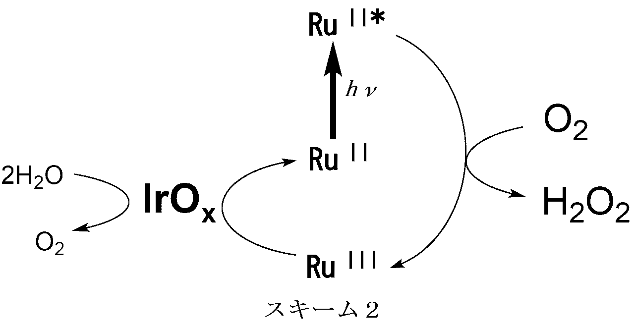
本発明の過酸化水素製造方法に用いる遷移金属錯体は、特に限定されないが、例えば、遷移金属原子に有機配位子が配位した(配位結合した)錯体であっても良い。配位結合は、特に限定されず、例えば、共有結合でも、イオン結合でも、両者の中間の性質を有する結合でも良い。前記有機配位子において、前記遷移金属原子に配位(配位結合)する原子は、特に限定されず、例えば、炭素原子でも炭素以外の原子でも良い。また、前記遷移金属原子は、中性原子に限定されず、イオンでも良く、その電荷(酸化数)は、任意である。

M1は遷移金属原子であり、
R1~R24は、それぞれ独立に、水素原子または任意の置換基であり、
または、R4およびR5は、一体となって -CH=CH- を形成しても良く、すなわち、R4およびR5はそれらの結合するビピリジン環と一体となってフェナントロリン環を形成しても良く、前記 -CH=CH- におけるHは、それぞれ独立に、任意の置換基で置換されていても良く、
R12およびR13は、一体となって -CH=CH- を形成しても良く、すなわち、R12およびR13はそれらの結合するビピリジン環と一体となってフェナントロリン環を形成しても良く、前記 -CH=CH- におけるHは、それぞれ独立に、任意の置換基で置換されていても良く、
R20およびR21は、一体となって -CH=CH- を形成しても良く、すなわち、R20およびR21はそれらの結合するビピリジン環と一体となってフェナントロリン環を形成しても良く、前記 -CH=CH- におけるHは、それぞれ独立に、任意の置換基で置換されていても良く、
mは、正の整数、0、または負の整数である。
R1~R24は、それぞれ独立に、水素原子、アルキル基、アリール基、ニトロ基、ハロゲン基、スルホン酸基(スルホ基)、アミノ基、アルキルアミノ基、カルボン酸基(カルボキシ基)、ヒドロキシ基、アルコキシ基、ペルフルオロアルキル基、アシル基、アルカノイル基、アシルオキシ基、またはアルカノイルオキシ基であることが好ましい。
または、
R4およびR5は、一体となって -CH=CH- を形成しても良く、すなわち、R4およびR5はそれらの結合するビピリジン環と一体となってフェナントロリン環を形成しても良く、前記 -CH=CH- におけるHは、それぞれ独立に、アルキル基、アリール基、ニトロ基、ハロゲン基、スルホン酸基(スルホ基)、アミノ基、アルキルアミノ基、カルボン酸基(カルボキシ基)、ヒドロキシ基、アルコキシ基、ペルフルオロアルキル基、アシル基、アルカノイル基、アシルオキシ基、またはアルカノイルオキシ基で置換されていても良く、
R12およびR13は、一体となって -CH=CH- を形成しても良く、すなわち、R12およびR13はそれらの結合するビピリジン環と一体となってフェナントロリン環を形成しても良く、前記 -CH=CH- におけるHは、それぞれ独立に、アルキル基、アリール基、ニトロ基、ハロゲン基、スルホン酸基(スルホ基)、アミノ基、アルキルアミノ基、カルボン酸基(カルボキシ基)、ヒドロキシ基、アルコキシ基、ペルフルオロアルキル基、アシル基、アルカノイル基、アシルオキシ基、またはアルカノイルオキシ基で置換されていても良く、 R20およびR21は、一体となって -CH=CH- を形成しても良く、すなわち、R20およびR21はそれらの結合するビピリジン環と一体となってフェナントロリン環を形成しても良く、前記 -CH=CH- におけるHは、それぞれ独立に、アルキル基、アリール基、ニトロ基、ハロゲン基、スルホン酸基(スルホ基)、アミノ基、アルキルアミノ基、カルボン酸基(カルボキシ基)、ヒドロキシ基、アルコキシ基、ペルフルオロアルキル基、アシル基、アルカノイル基、アシルオキシ基、またはアルカノイルオキシ基で置換されていても良い。
R1~R24が、それぞれ独立に、水素原子、炭素数1から6の直鎖もしくは分枝アルキル基、フェニル基、ニトロ基、ハロゲン基、スルホン酸基(スルホ基)、アミノ基、炭素数1から6の直鎖もしくは分枝アルキルアミノ基、カルボン酸基(カルボキシ基)、ヒドロキシ基、アルコキシ基、ペルフルオロアルキル基、炭素数1から6の直鎖もしくは分枝アルカノイル基、または炭素数1から6の直鎖もしくは分枝アルカノイルオキシ基であることがより好ましい。
または、
R4およびR5は、一体となって -CH=CH- を形成しても良く、すなわち、R4およびR5はそれらの結合するビピリジン環と一体となってフェナントロリン環を形成しても良く、前記 -CH=CH- におけるHは、それぞれ独立に、炭素数1から6の直鎖もしくは分枝アルキル基、フェニル基、ニトロ基、ハロゲン基、スルホン酸基(スルホ基)、アミノ基、炭素数1から6の直鎖もしくは分枝アルキルアミノ基、カルボン酸基(カルボキシ基)、ヒドロキシ基、アルコキシ基、ペルフルオロアルキル基、炭素数1から6の直鎖もしくは分枝アルカノイル基、または炭素数1から6の直鎖もしくは分枝アルカノイルオキシ基で置換されていても良く、
R12およびR13は、一体となって -CH=CH- を形成しても良く、すなわち、R12およびR13はそれらの結合するビピリジン環と一体となってフェナントロリン環を形成しても良く、前記 -CH=CH- におけるHは、それぞれ独立に、炭素数1から6の直鎖もしくは分枝アルキル基、フェニル基、ニトロ基、ハロゲン基、スルホン酸基(スルホ基)、アミノ基、炭素数1から6の直鎖もしくは分枝アルキルアミノ基、カルボン酸基(カルボキシ基)、ヒドロキシ基、アルコキシ基、ペルフルオロアルキル基、炭素数1から6の直鎖もしくは分枝アルカノイル基、または炭素数1から6の直鎖もしくは分枝アルカノイルオキシ基で置換されていても良く、
R20およびR21は、一体となって -CH=CH- を形成しても良く、すなわち、R20およびR21はそれらの結合するビピリジン環と一体となってフェナントロリン環を形成しても良く、前記 -CH=CH- におけるHは、それぞれ独立に、炭素数1から6の直鎖もしくは分枝アルキル基、フェニル基、ニトロ基、ハロゲン基、スルホン酸基(スルホ基)、アミノ基、炭素数1から6の直鎖もしくは分枝アルキルアミノ基、カルボン酸基(カルボキシ基)、ヒドロキシ基、アルコキシ基、ペルフルオロアルキル基、炭素数1から6の直鎖もしくは分枝アルカノイル基、または炭素数1から6の直鎖もしくは分枝アルカノイルオキシ基で置換されていても良い。


本発明において、前記遷移金属錯体は、市販品を用いても良いし、適宜製造(合成)しても良い。製造する場合、製造方法は特に制限されず、例えば、公知の製造方法により、または公知の製造方法を参考にして、適宜製造することができる。例えば、遷移金属の塩と配位子とを、それぞれ、水、アルコール等の溶媒に溶解させて混合させて製造しても良い。前記化学式(2)から(5)のいずれか(特に、前記化学式(4)または(5))で表される遷移金属錯体の場合は、例えば、下記参考文献1に記載の方法を参考にして製造しても良い。
Kotkar, D.; Ghosh, P. K. Inorg. Chem. 1987, 26, 208.またはYoung, R. C.; Meyer, T. J.; Whitten, D. G. J. Am. Chem. Soc.1976, 98, 286.
本発明において、水の酸化触媒は特に制限されないが、遷移金属酸化物またはオキソ錯体が好ましい。前記オキソ錯体としては、例えば、ルテニウムのオキソ錯体、マンガンのオキソ錯体、イリジウムのオキソ錯体等が挙げられる。前記水の酸化触媒は、例えば、ルテニウムのオキソ錯体、マンガンのオキソ錯体、イリジウムのオキソ錯体、鉄のオキソ錯体、インジウムオキサイド、ルテニウムオキサイド、イリジウムオキサイド、酸化タングステン、およびバナジン酸ビスマスからなる群から選択される少なくとも一つであることがより好ましい。また、前記水の酸化触媒は、例えば、IrO、Ir2O3、IrO2、IrO3、IrO4、WO3、BiVO4、Rb8K2[{Ru4O4(OH)2(H2O)4}(γ-SiW10O36)2]、Cs10[Ru4(μ-O)4(μ-OH)2(H2O)4(γ-SiW10O36)2]、Li10[Ru4(μ-O)4(μ-OH)2(H2O)4(γ-SiW10O36)2]、Li10[Ru4(μ-O)4(μ-OH)2(H2O)4(γ-SiW10O36)2]、Na10[{Ru4O4(OH)2(H2O)4}(γ-SiW10O36)2]、K10[{Ru4O4(OH)2(H2O)4}(γ-SiW10O36)2]、Rb10[{Ru4O4(OH)2(H2O)4}(γ-SiW10O36)2]、およびCs10[Ru4(μ-O)4(μ-OH)2(H2O)4(γ-SiW10O36)2]からなる群から選択される少なくとも一つであっても良い。
本発明において、前記水の酸化触媒の製造方法は特に制限されない。例えば、イリジウムオキサイドの場合は、前述のように、H2IrCl6・6H2OをNaOH水溶液中で加熱して製造しても良い。H2IrCl6・6H2Oの濃度は特に限定されないが、例えば1~300mmol/L、好ましくは10~80mmol/L、より好ましくは20~50mmol/Lである。NaOHの濃度も特に限定されないが、例えば0.001~10mmol/L、好ましくは0.05~1mmol/L、より好ましくは0.1~0.5mmol/Lである。加熱温度も特に限定されないが、例えば、40℃以上、好ましくは80℃以上であり、水の沸点付近(常圧で約100℃)で加熱することが特に好ましい。例えば、定法どおり、冷却管等を用いて還流させても良い。加熱時間も特に限定されないが、例えば2~100分間、好ましくは10~50分間、より好ましくは20~40分間である。なお、例えば、H2IrCl6・6H2Oに加え、またはこれに代えて、K2IrCl6等の他のイリジウム塩を用いても良い。また、例えば、NaOHに加え、またはこれに代えて、KOH等の他のアルカリ金属水酸化物、またはその他の無機塩基を用いても良い。製造したイリジウムオキサイドの精製法も特に限定されず、例えば、イリジウムオキサイドの沈殿を濾取し、必要に応じて水洗後、乾燥させても良い。
Hoertz, P. G.; Kim, Y. I.; Youngblood, W. J.; Mallouk, T. E. J. Phys. Chem. B 2007, 111 (24), 6845.
(1)トリス(2,2’-ビピリジル)ジクロロルテニウム(II)六水和物(Ru(bpy)3 2+)Cl2は、Aldrich社から購入した。トリス(2,2’-ビピリジル)ペルクロロルテニウム(III)塩(Ru(bpy)3 3+)Cl3は、Ru(bpy)3 2+を、0.5M H2SO4中、PbO2で酸化し、濃HClO4を加えて沈殿させて得た(V. Y. Shafirovich, V. V. Strelets, Bulletin of the Academy of Sciences of the USSR, Division of Chemical Sciences 1980, 7. および V. Y. Shafirovich, N. K. Khannanov, V. V. Strelets, Nouveau Journal de Chimie 1980, 4, 81.)。得られた(Ru(bpy)3 3+)Cl3は、減圧下で乾燥し、密封バイアル中、-18℃で保存し、1~2週間以内に使い切った。
合成したばかりのK8[γ-SiW10O36]・12H2O(4.00g, 1.33mmol)を65mLの水に溶解させ、さらに、RuCl3・H2Oの固体サンプル(0.60g, 2.67mmol)をすばやく加えた。RuCl3・H2Oを加えると、前記溶液の色はただちに褐色に変化し、pHは2.6まで下がった。さらに、この溶液に6M HClを滴下してpHを1.6に調整した。この溶液をさらに5分間攪拌した後、RbCl(2.4g, 20mmol)を10~15mLの水に溶かした溶液を少しずつ加えた。こうして得られた混合物を濾過し、濾液を室温で24時間静置したところ、褐色平板状の結晶が析出した。機器分析により、この褐色平板状の結晶が目的物であることを確認した。収量は1.8g(W基準で約40%収率)であった。以下に、機器分析値を示す。
ラマンスペクトル(in H2O, c=0.153mM; le=1064nm): 1066(w, br), 968(w), 871(w), 798(w, br), 604(w), 487(s), 427(s, br).
pH4.9(pH無調整):λmax=445nm、吸光定数εは未定量
pH2.5に調整後測定:λmax=445nm、吸光定数ε=2.8×10⁴M-1cm-1
(1)セシウム塩Cs10[Ru4(μ-O)4(μ-OH)2(H2O)4(γ-SiW10O36)2]の合成
262mg(0.359mmol)のK4Ru2OCl10を30mlの脱イオン水に溶かし、さらに、1g(0.336mmol)のK8γ-SiW10O36-12H2Oを加えた。得られた暗褐色溶液のpHは、6.2であった。この溶液を70℃で1時間加熱し、pHが1.8になったところで濾過した。さらに、濾液に過剰量のCsCl(4.4g, 26.1mmol)を加え、沈殿を得た。この沈殿を、2~3mLの冷水で3回洗浄し、目的物のセシウム塩Cs10[Ru4(μ-O)4(μ-OH)2(H2O)4(γ-SiW10O36)2]を980mg(85%)得た。
上記により得られたセシウム塩Cs10[Ru4(μ-O)4(μ-OH)2(H2O)4(γ-SiW10O36)2]を100mlの水に溶かし、陽イオン交換樹脂を透過させてリチウム塩Li10[Ru4(μ-O)4(μ-OH)2(H2O)4(γ-SiW10O36)2]を800mg得た。この未精製リチウム塩の水溶液を、セファデックス(商品名)G-50を固定相としたカラムに通し、最初の約50mgのフラクションを捨てることにより精製した。水および前記固定相の分量は、前記リチウム塩1gに対し水5mL、および前記固定相10gの比率とした。溶出物から溶媒を留去し、700mgの精製リチウム塩を得た(Wに基づく収率75%)。なお、目的物の全溶出後も前記カラムの固定相は黒く着色したままであったが、これは、幾分かの低分子量ルテニウム化学種が残留していたためと推測される。
なお、サンプルを元素分析前に乾燥させたところ、3.85%の質量が減少した。これは、Cs10[Ru4(μ-O)4(μ-OH)2(H2O)4(γ-SiW10O36)2]に対する水和水15分子に相当する。
Rラマンスペクトル:483(s), 804(w), 870(m), 950(m) cm-1.
リチウム塩Li10[Ru4(μ-O)4(μ-OH)2(H2O)4(γ-SiW10O36)2]のUV-VisスペクトルはpH依存的であった。すなわち、酸性領域では、最大吸収波長λmax(nm)=443nmにおける吸光係数ε(M-1cm-1)が増大し、pH2.0以下では、logε=4.57であった。これは、ルテニウムd-d繊維に由来すると推測される。これに対し、pH未調整の場合は、前記443nmの吸収は増大せず、連続的な吸収が観測されるのみであった。これは、ルテニウムからタングステンへの電荷移動帯に由来すると推測される。また、UV-Visスペクトルの可逆的な変化から、pKa=3.62であると見積もられた。水配位子の一つが脱プロトンを起こし、[Ru4(μ-O)4(μ-OH)2(H2O)3(OH)(γ-SiW10O32)2]11-を形成していると考えられる。
について、HNO3(1M)を加えて[Ru4(μ-O)4(μ-OH)2(H2O)3(OH)(γ-SiW10O32)2]11-の分光光度滴定を行い、λ=443nmの吸光度をプロットした。その結果、pKa=3.62と計算された。また、同様に、リチウム塩Li10[Ru4(μ-O)4(μ-OH)2(H2O)4(γ-SiW10O36)2]([Ru4(μ-O)4(μ-OH)2(H2O)3(OH)(γ-SiW10O32)2]11-)水溶液(10-2M, pH 4.97)についてHNO3(1M)を加えて酸塩基滴定を行ったところ、pKa=3.7と見積もられ、分光光度滴定の結果と良い一致を示した。また、前記酸塩基滴定における[H+]対[HNO3]/[POM]のプロット比から、1:1の化学量論関係が見出された。なお、前記酸塩基滴定にいて、[H+]は水素イオン濃度を示し、[HNO3]は硝酸濃度を示し、[POM]は、リチウム塩Li10[Ru4(μ-O)4(μ-OH)2(H2O)4(γ-SiW10O36)2]([Ru4(μ-O)4(μ-OH)2(H2O)3(OH)(γ-SiW10O32)2]11-)の濃度を示す。
リチウム塩Li10[Ru4(μ-O)4(μ-OH)2(H2O)4(γ-SiW10O36)2]の水溶液(10-3M)に濃H2SO4を加えてpHを0.60とし、サイクリックボルタンメトリーを測定した。静止電位の測定値は0.72V(Ag/AgCl参照電極)であった。測定条件は、初期電位=0.72V; スイッチング電位(1)=1.4V; スイッチング電位(2)=0V; 最終電位=0.72V; スキャン速度=100mVs-1とした。サイクリックボルタンメトリーは、+1.4~-0.0V(vs Ag/AgCl)間で、4つの陽極波と4つの陰極波を示した。4つのほぼ可逆的な酸化還元対が、E1/2=+1.12, +0.70, +0.53,および+0.29Vにおいて、ピーク分離ΔEp(=Epa-Epc)=89, 98, 59,および166mVで観測された。スキャンの方向を逆にしても、同様の酸化還元波が観測された。
本発明の過酸化水素製造方法は、前述のとおり、水、水の酸化触媒、遷移金属錯体、および酸素(O2)を含む反応系に光照射して過酸化水素を発生させる過酸化水素発生工程を含むことを特徴とする。それ以外は、本発明の過酸化水素製造方法は特に限定されないが、例えば、以下のようにして行うことができる。
本発明の過酸化水素製造用キットは、前述のとおり、前記本発明の過酸化水素製造方法に用いる前記遷移金属錯体と、前記水の酸化触媒とを含む。これ以外は特に制限されず、前記遷移金属錯体と、前記水の酸化触媒以外の他の構成要素を適宜含んでいても良いし、含んでいなくても良い。前記他の構成要素としては、例えば、前述の光源等が挙げられる。本発明の過酸化水素製造用キットは、その構成、スケール等を工夫することで、実験室用、工業用等、幅広い用途に用いることができる。
本発明の燃料電池は、前述のとおり、燃料容器と、燃料電池セルとを含む燃料電池であって、前記燃料容器内に、前記本発明の過酸化水素製造方法に用いる前記遷移金属錯体と、前記水の酸化触媒とを含むことを特徴とする。これ以外には、本発明の燃料電池は特に限定されないが、例えば、以下のとおりである。
アノード側:H2O2/O2+2H++2e- [1]
カソード側:H2O2+2H++2e-/2H2O [2]
全体の反応:2H2O2/O2+2H2O [3]
Chem. Commun., 2010, 46, 7334-7336
[参考文献4]
“Protonated iron-phthalocyanine complex used for cathode material of a hydrogen peroxide fuel cell operated under acidic conditions”, Yusuke Yamada, Sho Yoshida, Tatsuhiko Honda and Shunichi Fukuzumi; Energy Environ. Sci., 2011, First published on the web 16 Jun 2011
(※参考文献4のElectronic Supplementary Informationは、本願出願日現在、http://www.rsc.org/suppdata/ee/c1/c1ee01587g/c1ee01587g.pdfからダウンロード可能)

[Fe(TPP)Cl]、[Fe(OEP)Cl]または[Fe(Pc)Cl]を、ベンゾニトリル(0.60mg、1mL)に溶かし、溶液を作製した。[Fe(Pc)Cl]の場合は、溶解度を上げるために、前記溶液に微量のトリフルオロ酢酸を加えた。前記溶液を、少量(7.0μL)、グラッシーカーボン電極(0.071cm2)上に塗布し、乾燥機中、70℃で40分間乾燥させた。前記Fe錯体で修飾した電極を、10μLのNafion(商品名)溶液(MeOH、0.05%)に浸漬させ、乾燥機中、70℃で40分間乾燥させることにより、Nafionでコーティングした。前記グラッシーカーボン電極上に固定されたFe錯体の量は、H2O2を含まない溶液中におけるFeIII/FeII還元電流に基づいて算出した。[Fe(TPP)Cl]、[Fe(OEP)Cl]および[Fe(Pc)Cl]の還元のための電荷は、それぞれ、3.6×10-7、7.6×10-7および2.9×10-6Cであった。これらの電荷は、それぞれの錯体の3.7×10-12、7.9×10-12および3.0×10-11molに相当する。
Fe錯体で修飾した電極におけるH2O2の挙動は、ALS 630B electrochemical analyzer(商品名)を用いて検証した。飽和カロメル電極および白金電極を、それぞれ参照電極および対極として用いた。[Fe(TPP)Cl]、[Fe(OEP)Cl]または[Fe(Pc)Cl]を固定したグラッシーカーボン電極を、作用極として用いた。測定は、3mMのH2O2を含む酢酸緩衝溶液(pH4)を用い、室温で行った。
H2O2溶液を含むpH3~5の緩衝溶液(300mM)を、一隔室(one-compartment)の電気化学セル中に入れた。Ni電極および[Fe(TPP)Cl]、[Fe(OEP)Cl]または[Fe(Pc)Cl]を固定したグラッシーカーボン電極を、前記H2O2溶液中に浸漬させた。セルの性能は、BAS 100W(商品名)を用いて評価した。測定は、脱貴した酢酸緩衝溶液を用いて室温で行った。

ANALYST, NOVEMBER 1992, VOL. 117, 1781-1784
[参考文献6]
Bull. Chem. Soc. Jpn., 76, 1873
過酸化水素の製造に用いるイリジウムオキサイド(水の酸化触媒)は、以下のようにして合成した。すなわち、まず、市販品のH2IrCl6・6H2O(1g)に水を50mL加えて攪拌した。NaOH水溶液(5M)を加えてpHの値を10にして、オイルバスで100℃に30分間加熱した。これを室温で放置し、濾過して固体を得た。これを、真空ポンプを用いて常温で乾燥し、さらに、空気中で65℃で12時間乾燥してIrOxを得た。なお、このIrOxにおいて、xは、未知(未確認)の数である。以下において、IrOxと記載する場合、特に断らない限り、この自家調製したIrOxを表す。また、図1~22中において、「Ir(OH)3」と表記している場合があるが、この表記は、前記IrOxと同義である。「Ir(OH)3」との表記を用いている理由は、後述の参考例3に示すように、XPS測定により、IrOx表面にIr(OH)3が多く存在すると推測されたためである。ただし、この表記は、便宜上の表記であり、IrOxの構造を限定するものではない。
H2SO4水溶液(2M,3.0mL)に、[RuII(Me2-phen)3]Cl2(20μM)とIrOx(3.0mg)を加えて、スターラーバーを投入後、ラバーセプタムを使用して光路長1cmの二面セルに封入し、酸素ガス置換を行った。すなわち、このようにして、水、水の酸化触媒(IrOx)、遷移金属錯体([RuII(Me2-phen)3]Cl2)、および酸素(O2)を含む反応系を準備した。なお、[RuII(Me2-phen)3]Cl2は、前記化学式(4)で表されるルテニウム2価錯体を表す。つぎに、前記反応系に、キセノンランプ光源(Ushio Optical Modulex SX-UID 501XAMQ)を用いて、色ガラスフィルター(L42、AGCテクノグラス)を通して波長420nm以下の光をカットし、波長420nmを超える(波長λ>420nm)光のみを照射して、反応させた。反応後の過酸化水素の定量は、市販品のTiO(tpypH4)4+塩を用いて行った。すなわち、まず、HCl水溶液(50mM)にTiO(tpypH4)4+(50μM)を加えてTi-TPyP試薬を調製した。一方、前記反応終了後の反応系(反応溶液)を濾過して不溶物を除去し、水で希釈した。この溶液0.25mLにHClO4(4.8M)を0.25mL、Ti-TPyP試薬を0.25mL加えて5分間放置した。放置後の溶液を水で2.5mLに希釈して可視吸収スペクトルを測定し、過酸化水素を定量した。なお、希硫酸の電離度は、ほぼ100%であることから、例えば、硫酸H2SO4濃度が2Mの水溶液のpHは、約-0.60(マイナス0.60)と推定することができる。
Nocera, D. G.; Turro, C.; Zaleski, J. M.; Karabatsos, Y. M. J. Am. Chem. Soc. 1996, 118, 6060.
H2SO4水溶液(2M,3.0mL)に[RuII(Me2-phen)3]Cl2(20μM)とIrOx(3.0mg)を加えて、スターラーバーを投入後、ラバーセプタムを使用して光路長1cmの二面セルに封入し、酸素ガス置換を行った。これに、株式会社島津製作所製のSHIMADZU蛍光分光光度計RF-5300PC(商品名)を用いてスリット幅5でし、反応させた。反応後の過酸化水素の定量はTiO(tpypH4)4+を用いて行った。この時の光強度は1.1×10⁻⁹einstein s-1であった。
反応系に水の酸化触媒を加えない以外は実施例2と同様にして反応を行った。さらに、系中に酸素(O2)を存在させない(アルゴン置換して脱酸素する)以外は前記と同様にして反応を行った。図5に、それらの結果を示す。同図下段のグラフは、反応終了後の水溶液の蛍光スペクトル図であり、横軸は波長(nm)を表し、縦軸は蛍光強度(相対値)を表す。同図において、実線が、酸素(O2)を存在させずに光照射した後の蛍光スペクトルであり、破線が、酸素(O2)の存在下で光照射した後の蛍光スペクトルである。また、同図上段のスキームは、酸素(O2)が存在する場合の、推定される反応機構である。グラフに示す通り、酸素を酸素(O2)を存在させずに光照射した後は、[RuII(Me2-phen)3]2+に基づく蛍光スペクトルを示したが、酸素(O2)の存在下で光照射した後は、蛍光がほとんど消失していた。これは、酸素(O2)が存在しない場合はほとんど反応が起こらず、酸素(O2)が存在した場合は、同図のスキームに示す通り、[RuII(Me2-phen)3]2+と酸素(O2)とが反応して[RuIII(Me2-phen)3]3+(3価のルテニウムイオン)と過酸化水素とを生じたためと推測される。ただし、本参考例の場合、実施例1のように[RuII(Me2-phen)3]2+が触媒的に働くことはなく、過酸化水素はわずかしか発生しなかった。これは、水の酸化触媒が存在せず、生じた[RuIII(Me2-phen)3]3+(3価のルテニウムイオン)が還元されない(2価のルテニウムイオンに戻らない)ために、[RuII(Me2-phen)3]2+(2価のルテニウムイオン)が消費されつくした段階で過酸化水素の生成が停止したためと推測される。
遷移金属錯体として、[RuII(Me2-phen)3]Cl2(前記化学式(4)で表されるルテニウム錯体の塩、実施例1と同じ)または[RuII(bpy)3]Cl2(前記化学式(5)で表されるルテニウム錯体の塩)を用いることと、硫酸H2SO4の濃度を種々変化させることと、水の酸化触媒(IrOx)を用いないこと以外は、実施例1と同様にして、光照射時間(反応時間)30分で反応させた。図7のグラフに、その結果を示す。同図において、横軸は、硫酸H2SO4の濃度(M)である。縦軸は、ルテニウム3価錯体の濃度(μM)または過酸化水素H2O2の濃度(μM)である。図示のとおり、いずれの錯体を用いた場合も、硫酸濃度が高いほど過酸化水素発生量が多かった。これは、プロトン濃度が高い方が、酸素(O2)から過酸化水素を生成する反応が起こりやすいためと考えられる。また、硫酸濃度が同じ場合、[RuII(Me2-phen)3]Cl2(前記化学式(4)で表されるルテニウム錯体の塩、実施例1と同じ)のほうが過酸化水素発生量が多かった。なお、生成した過酸化水素とルテニウム錯体の濃度は、図示のとおり、良い一致を示した。
遷移金属錯体として、[RuII(Me2-phen)3]Cl2(前記化学式(4)で表されるルテニウム錯体の塩、実施例1と同じ)または[RuII(bpy)3]Cl2(前記化学式(5)で表されるルテニウム錯体の塩)を用いることと、硫酸H2SO4の濃度を調整して反応系のpHを0にすることと、IrOxの使用量を1.5mgにすること以外は実施例1と同様にして、光照射時間(反応時間)3時間で反応させた。図8に、その結果を示す。同図右側のグラフにおいて、横軸は、遷移金属錯体の種類(前記化学式(4)または(5))を表し、縦軸は、3時間反応させた後の、反応系中(水中)の過酸化水素H2O2の濃度(μM)を表す。図示のとおり、いずれの遷移金属錯体を用いても、効率よく過酸化水素H2O2を得ることができた。また、[RuII(Me2-phen)3]Cl2(前記化学式(4)で表されるルテニウム錯体の塩、実施例1と同じ)を用いた方が、[RuII(bpy)3]Cl2(前記化学式(5)で表されるルテニウム錯体の塩)を用いるよりも、過酸化水素H2O2の収量がさらに多かった(約2倍)。
硫酸H2SO4の濃度を種々変化させることと、IrOxの使用量を1.5mgにすること以外は実施例1と同様にして、光照射時間(反応時間)30分間で反応させた。その結果を、図9Aに示す。図中央のグラフにおいて、横軸は、反応系中(水中)における硫酸H2SO4の濃度(M)を表し、縦軸は、反応後の過酸化水素H2O2の濃度(μM)を表す。図示のとおり、硫酸濃度を0~5Mまで変化させたところ、2Mのときが最も反応後の過酸化水素H2O2の濃度が高かった(すなわち、生成量が多かった)。この理由は、以下のように推測される。すなわち、同図左側の模式図に示すように、硫酸濃度が低い(すなわち、pHが高く酸性が弱い)条件では、IrOxによる水の酸化反応(H2OからO2の発生)が起こりやすいために、遷移金属錯体によるO2の還元反応(H2O2の発生)が律側段階になると考えられる。逆に、硫酸濃度が高い(すなわち、pHが低く酸性が強い)条件では、O2の還元反応(H2O2の発生)が起こりやすいために、IrOxによる水の酸化反応(H2OからO2の発生)が遷移金属錯体による律側段階になると考えられる。これらのバランスの観点から、本実施例の反応系では、硫酸濃度が2Mのときが最もH2O2の発生効率が良かったと推測される。また、IrOxの使用量を3.0mgにすることと、光照射時間(反応時間)0から3hまで追跡すること以外は図9Aと同条件で反応させた結果を、図9Bに示す。図示のとおり、図9Bの反応条件でも、図9Aの反応条件と同様、同じ反応時間での過酸化水素濃度は、硫酸濃度の上昇(0.5M<1M<2M)に伴い増加した。また、図9B中には図示していないが、図9Bの反応条件で、硫酸濃度3Mおよび4Mの場合は、図9Aと同様、硫酸濃度0.5Mの場合よりも過酸化水素濃度が低かった。
IrOxの使用量を種々変化させる以外は実施例1と同様にして、光照射時間(反応時間)30分で反応を行った。結果を、図10A左側のグラフに示す。同グラフにおいて、横軸は、IrOxの使用量(mg)を表し、縦軸は、反応後の過酸化水素H2O2の濃度(μM)を表す。図示のとおり、IrOxの使用量が3mgのときが最も反応後の過酸化水素H2O2の濃度が高かった(すなわち、生成量が多かった)。また、光照射時間(反応時間)を1時間にする以外は図10A左側のグラフと同条件で反応させた結果を、図10Bのグラフに示す。同グラフにおいて、横軸は、IrOxの使用量(mg)を表し、縦軸は、反応後の過酸化水素H2O2の濃度(μM)を表す。図示のとおり、反応時間1時間でも、反応時間30分の場合(図10A左側のグラフ)と同様、IrOxの使用量が3mgのときが最も反応後の過酸化水素H2O2の濃度が高かった(すなわち、生成量が多かった)。このような結果となった理由は明らかではないが、IrOxの使用量が多すぎると、反応系中に分散(懸濁)したIrOxにより、遷移金属錯体による光の吸収(励起)が妨げられやすいため、IrOxの使用量が3mgのときが最もバランスが良かったと考えられる。
IrOxまたは市販のイリジウム(IV)オキサイドすなわちIrO2(純度99%m、製造元:STREM CHEMICALS社)を3mg用いること以外は実施例1と同様にして、光照射時間(反応時間)30分で反応を行った。結果を、図10A右側のグラフに示す。横軸は、IrOxまたは市販のIrO2のどちらかを用いた場合を表し、縦軸は、反応後の過酸化水素H2O2の濃度(μM)を表す。図示のとおり、IrOxを用いた場合(実施例1と同じ条件)は、効率よく過酸化水素H2O2を得ることができたが、前記市販のIrO2を用いた場合は、ほとんど過酸化水素H2O2が得られなかった。これは、前記市販のIrO2は、ほとんどが沈殿してしまい、反応系中(水中)に効率よく分散しなかったためである。また、光照射時間(反応時間)を1時間にする以外は図10A右側のグラフと同条件で反応させた結果を、図10Cのグラフに示す。同グラフにおいて、横軸は、IrOxまたは市販のIrO2のどちらかを用いた場合を表し、縦軸は、反応後の過酸化水素H2O2の濃度(μM)を表す。図示のとおり、反応時間を1時間にしても、IrOxを用いた場合は、効率よく過酸化水素H2O2を得ることができ、前記市販のIrO2を用いた場合は、ほとんど過酸化水素H2O2が得られなかった。なお、IrOxと市販のIrO2とでこのように過酸化水素H2O2の発生量に違いが生じる理由は明らかではないが、IrOxの表面に水酸基(OH)が存在し、その水酸基が、水への分散性またはIrOxの反応性自体を促進している可能性がある。
IrOx(12mg)を光路長1cmの二面セルに入れ、ラバーセプタムを使用して空気中で密封し、これに対して大気下で調整した[RuIII(Me2-phen)3]3+水溶液をシリンジで加えることで反応を開始した。次に、酸素センサー(FOXY Fiber Optic Oxygen Sensor、Ocean Optics社製)を用いて、この溶液の酸素濃度の定量を行いながら室温(298K)で、光を照射せずに静置して4時間反応させた。酸素センサーは、その配線がセプタムラバーを貫通することでセンサー検知部位を溶液中で封入し、設置した。すなわち、このようにして、水、水の酸化触媒(IrOx)、酸化剤となる遷移金属錯体([RuIII(Me2-phen)3]3+)を含む反応系を準備し、反応の進行に伴って生成する酸素の定量を行った。上述の[RuIII(Me2-phen)3]3+水溶液(0.5mMのH2SO4酸性水溶液、pH 0、12mL)の調整は、次に記述する方法で行った。あらかじめpH 0の硫酸酸性の[RuII(Me2-phen)3]Cl2(0.5mM)の水溶液(12mL)を用意して氷冷し、これに二酸化鉛(PbO2、ナカライテスク社製)の粉末(100mg)を加えて懸濁させ、マグネチックスターラーによりスターラーバーで懸濁液を氷冷しながら5分間撹拌することで、二酸化鉛による[RuII(Me2-phen)3]Cl2の酸化反応が進行した。この懸濁液を室温でシリンジフィルター(品番:DISMIC-13 PTFE 0.45μm、型番:HP045AN、Toyo Roshi Kaisha Ltd.製)を用いてろ過し、[RuIII(Me2-phen)3]3+を含むろ液を[RuIII(Me2-phen)3]3+水溶液としてそのまま反応に供した。図15の左側の図は、参考例4において起こった反応の機構を推定する模式図である。図示のように、参考例4では、過酸化水素の発生が確認されず、水の酸化触媒による酸素(O2)の発生のみが確認された。その結果を、図15右側のグラフに示す。同図において、横軸は、反応時間(h)を表し、縦軸は、反応系(反応溶液)中における酸素の濃度(μM)を表す。図示のとおり、酸素(O2)発生量は、3~4時間の反応で、約0.8μmolに達し、酸素センサーによる測定に基づいて算出した酸素(O2)収率は、53%であった。
光路長1cmの二面セル内の反応系に、さらに、硝酸スカンジウム(III)(Sc(NO3)3)を0.1M加えること以外は実施例1と同様にし、波長420nmを超える(波長λ>420nm)光のみを照射して、反応させた。図16右上のグラフに、その結果を示す。同図において、横軸は、反応時間(h)を表し、縦軸は、反応系(反応溶液)中における過酸化水素の濃度(μM)を表す。過酸化水素の定量は、実施例1と同じく、市販品のTiO(tpypH4)4+塩を用いて行った。なお、図16下側中央のグラフは、TiO(tpypH4)4+およびTiO2(tpypH4)4+の可視吸収スペクトルの変化を示す。同図において、横軸は、波長(nm)を表し、縦軸は、吸光度を表す。また、図16左上のスキームは、本実施例(実施例6)の反応機構を推定する模式図である。
光路長1cmの二面セル内の反応系に、さらに、硝酸スカンジウム(III)(Sc(NO3)3)を0.1M加えること以外は実施例2と同様にし、単一波長定常光(λ=450nm)を照射して反応させた。図17に、その結果を示す。同図右上のグラフにおいて、横軸は、反応時間(h)を表し、縦軸は、反応系(反応溶液)中における過酸化水素の濃度(μM)を表す。過酸化水素の定量は、実施例6と同じく、市販品のTiO(tpypH4)4+塩を用いて行った。なお、同図左側のスキームは、本実施例(実施例7)の反応機構を推定する模式図である。
光路長1cmの二面セル内の反応系にIrOxを加えないこと以外は実施例7と同様にし、単一波長定常光(λ=450nm)を照射して反応させた。図18の左側の図に、その結果を示す。図18左側中央のグラフにおいて、横軸は、反応時間(分)を表し、縦軸は、反応系(反応溶液)中におけるRu3+イオン濃度を表す。また、図18左上のスキームは、本実施例(実施例8)の反応機構を推定するスキームである。グラフに示すとおり、過酸化水素の発生により、Ru2+が酸化されてRu3+イオンが生成した。ただし、本参考例では、水の酸化触媒を用いていないために、水の酸化による酸素(O2)の発生が起こらず、反応系中の酸素(O2)を使いつくしたところで、過酸化水素の発生が起こらなくなった。
下記(1)~(5)のそれぞれの条件で、光路長1cmの二面セルを用い、波長420nmを超える(波長λ>420nm)光のみを照射して、反応させた。なお、下記(3)~(5)は、いずれも、スカンジウムイオン(III)(Sc3+)濃度が、等しく0.1Mとなるように調整している。
(1) 実施例1と同じ条件
(2) 希硫酸を水に変える以外は実施例1と同じ条件
(3) 希硫酸を水に変えて、かつ、硝酸スカンジウム(III)(Sc(NO3)3)を0.1M加えること以外は実施例1と同じ条件(すなわち、希硫酸を水に変えること以外は、実施例6と同じ条件)
(4) 硝酸スカンジウム(III)(Sc(NO3)3)0.1Mを硫酸スカンジウム(III)(Sc2(SO4)3)0.05Mに変える以外は(3)と同じ条件
(5) 硝酸スカンジウム(III)(Sc(NO3)3)0.1Mをトリフルオロメタンスルホン酸スカンジウム(III)(Sc(OTf)3)0.1Mに変えること以外は(3)と同じ条件
硝酸スカンジウム(III)(Sc(NO3)3)の濃度を、0~100mM(0.1M)まで種々変化させること以外は実施例6と同様にし、波長420nmを超える(波長λ>420nm)光のみを照射して、反応させた。図19左側のグラフに、その結果を示す。同図において、横軸は、硝酸スカンジウム(III)(Sc(NO3)3)の濃度を表し、縦軸は、反応開始後3hにおける反応系中の過酸化水素濃度(μM)を表す。図示のとおり、触媒反応で生成する過酸化水素量は、スカンジウムイオン(硝酸スカンジウム)濃度にほぼ比例した。すなわち、硝酸スカンジウム(III)(Sc(NO3)3)の濃度が高いほど、反応系中における触媒の活性が高くなり、過酸化水素発生量が多くなった。
硝酸スカンジウム(III)(Sc(NO3)3)0.1Mを、硝酸イットリウム(III)(Y(NO3)3)0.1M、硝酸ルテチウム(III)(Lu(NO3)3)0.1M、硝酸亜鉛(II)(Zn(NO3)2)0.1M、または硝酸マグネシウム(II)(Mg(NO3)2)0.1Mにそれぞれ変える以外は実施例6と同様にし、波長420nmを超える(波長λ>420nm)光のみを照射して、反応させた。また、反応系に硝酸スカンジウム(III)(Sc(NO3)3)0.1Mを加えない以外は実施例6と同様(実施例1と同条件)で反応させた。これらの結果を、実施例6と対比した。結果を、図19右側のグラフに示す。グラフの縦軸は、反応開始後3hにおける反応系中の過酸化水素濃度(μM)を表す。なお、図19上部のスキームは、本実施例の反応機構を推定するスキームである。また、図19右下の図は、金属イオンのルイス酸性の強さを示す模式図である。図示のとおり、Zn2+、Mg2+およびZn2+よりも、Y3+およびLu3+の方がルイス酸性が強く、それらよりもSc3+の方がさらにルイス酸性が強い。
実施例6と同様にし、波長420nmを超える(波長λ>420nm)光のみを照射して、反応させた。この条件で長時間反応させて、IrOx(水の酸化触媒)の耐久性を確認した。図20左側のグラフに、その結果を示す。同グラフにおいて、横軸は、反応時間(h)を表す。縦軸は、横軸に対応する反応時間における反応系中の過酸化水素濃度(μM)を表す。図示のとおり、[RuII(Me2-phen)3]Cl2が活性を失って、過酸化水素濃度が上昇しなくなった時点(反応後6時間および12時間)で、反応系中に再度、初期濃度と同じ[RuII(Me2-phen)3]Cl2を追加して反応を再開すると、再度過酸化水素が発生した。このようにして、18時間反応を続けても、IrOxの触媒活性は、ほとんど低下しなかった。
実施例6と同じ反応条件で、長時間反応させて、触媒としての[RuII(Me2-phen)3]Cl2の耐久性を確認した。図20右側のグラフに、その結果を示す。同グラフにおいて、横軸は、反応時間(h)を表す。縦軸は、横軸に対応する反応時間における反応系中の過酸化水素濃度(μM)を表す。図示のとおり、反応後4~5時間で、反応系中の過酸化水素濃度は、ほぼ上昇しなくなったが、反応後5時間の時点で再度、初期導入量と同じIrOx(水の酸化触媒)を加えると、再度、過酸化水素が発生した。図示のとおり、8時間以上反応させても、[RuII(Me2-phen)3]Cl2は、触媒としての活性を維持していた。
[RuII(Me2-phen)3]Cl2の濃度を20μMよりも低くすること以外は実施例1と同条件で反応を行った。[RuII(Me2-phen)3]Cl2の濃度を4.0μMまたは2.0μMとした場合の過酸化水素発生量および触媒回転数(TON)を、[RuII(Me2-phen)3]Cl2の濃度が20μMの場合(実施例1)と併せて、図21に示す。図21のグラフにおいて、横軸は、反応時間(光照射時間)であり、縦軸は、反応系(反応溶液)中の過酸化水素濃度(μM)である。図示のとおり、[RuII(Me2-phen)3]Cl2の濃度を4.0μMまたは2.0μMとした場合、過酸化水素濃度(発生量)自体は、[RuII(Me2-phen)3]Cl2の濃度が20μMの場合よりも低下した。しかし、TONについては、[RuII(Me2-phen)3]Cl2の濃度が20μMの場合よりも飛躍的に上昇した。すなわち、[RuII(Me2-phen)3]Cl2の濃度が4.0μMの場合は、[RuII(Me2-phen)3]Cl2量を基準にしたTONが111であり、[RuII(Me2-phen)3]Cl2の濃度が2.0μMの場合は、[RuII(Me2-phen)3]Cl2量を基準にしたTONが158であった。これらのTONの数値は、[RuII(Me2-phen)3]Cl2の濃度が20μMで硝酸スカンジウム(III)を加えた実施例6の数値(TON=52)の2倍または3倍以上である。すなわち、反応条件の最適化により、TONを飛躍的に向上できることが確認された。さらに、[RuII(Me2-phen)3]Cl2の濃度を1.0μMとする以外は同条件で反応させた場合の過酸化水素発生量および[RuII(Me2-phen)3]Cl2量を基準にした触媒回転数(TON)を、図22に示す。図22のグラフにおいて、横軸は、反応時間(光照射時間)であり、縦軸は、反応系(反応溶液)中の過酸化水素濃度(μM)である。図示のとおり、この反応条件では、TON=307という驚異的な数値が得られた。
Claims (15)
- 過酸化水素製造方法であって、
水、水の酸化触媒、遷移金属錯体、および酸素(O2)を含む反応系に光照射して過酸化水素を発生させる過酸化水素発生工程を含むことを特徴とする、過酸化水素製造方法。 - 前記遷移金属錯体が、遷移金属原子に芳香族配位子が配位した錯体である請求項1に記載の過酸化水素製造方法。
- 前記遷移金属錯体が、下記化学式(1)で表される錯体である請求項2に記載の過酸化水素製造方法。
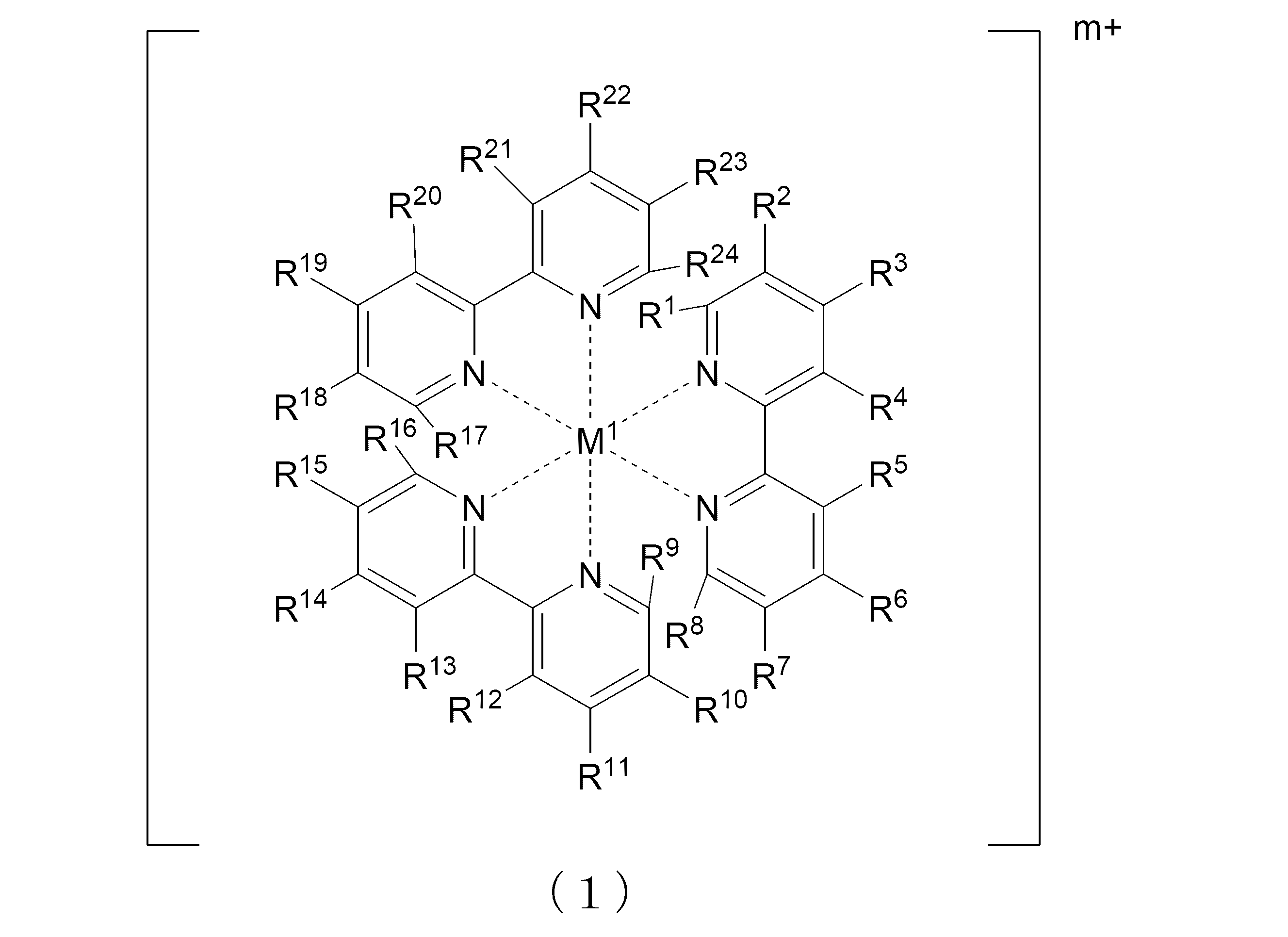
M1は遷移金属原子であり、
R1~R24は、それぞれ独立に、水素原子または任意の置換基であり、
または、R4およびR5は、一体となって -CH=CH- を形成しても良く、すなわち、R4およびR5はそれらの結合するビピリジン環と一体となってフェナントロリン環を形成しても良く、前記 -CH=CH- におけるHは、それぞれ独立に、任意の置換基で置換されていても良く、
R12およびR13は、一体となって -CH=CH- を形成しても良く、すなわち、R12およびR13はそれらの結合するビピリジン環と一体となってフェナントロリン環を形成しても良く、前記 -CH=CH- におけるHは、それぞれ独立に、任意の置換基で置換されていても良く、
R20およびR21は、一体となって -CH=CH- を形成しても良く、すなわち、R20およびR21はそれらの結合するビピリジン環と一体となってフェナントロリン環を形成しても良く、前記 -CH=CH- におけるHは、それぞれ独立に、任意の置換基で置換されていても良く、
mは、正の整数、0、または負の整数である。 - 前記化学式(1)中、M1が、ルテニウム、オスミウム、鉄、マンガン、クロム、コバルト、イリジウム、またはロジウムである請求項3記載の過酸化水素製造方法。
- 前記化学式(1)中、
R1~R24が、それぞれ独立に、水素原子、アルキル基、アリール基、ニトロ基、ハロゲン基、スルホン酸基(スルホ基)、アミノ基、アルキルアミノ基、カルボン酸基(カルボキシ基)、ヒドロキシ基、アルコキシ基、ペルフルオロアルキル基、アシル基、アルカノイル基、アシルオキシ基、またはアルカノイルオキシ基であり、
または、
R4およびR5は、一体となって -CH=CH- を形成しても良く、すなわち、R4およびR5はそれらの結合するビピリジン環と一体となってフェナントロリン環を形成しても良く、前記 -CH=CH- におけるHは、それぞれ独立に、アルキル基、アリール基、ニトロ基、ハロゲン基、スルホン酸基(スルホ基)、アミノ基、アルキルアミノ基、カルボン酸基(カルボキシ基)、ヒドロキシ基、アルコキシ基、ペルフルオロアルキル基、アシル基、アルカノイル基、アシルオキシ基、またはアルカノイルオキシ基で置換されていても良く、
R12およびR13は、一体となって -CH=CH- を形成しても良く、すなわち、R12およびR13はそれらの結合するビピリジン環と一体となってフェナントロリン環を形成しても良く、前記 -CH=CH- におけるHは、それぞれ独立に、アルキル基、アリール基、ニトロ基、ハロゲン基、スルホン酸基(スルホ基)、アミノ基、アルキルアミノ基、カルボン酸基(カルボキシ基)、ヒドロキシ基、アルコキシ基、ペルフルオロアルキル基、アシル基、アルカノイル基、アシルオキシ基、またはアルカノイルオキシ基で置換されていても良く、
R20およびR21は、一体となって -CH=CH- を形成しても良く、すなわち、R20およびR21はそれらの結合するビピリジン環と一体となってフェナントロリン環を形成しても良く、前記 -CH=CH- におけるHは、それぞれ独立に、アルキル基、アリール基、ニトロ基、ハロゲン基、スルホン酸基(スルホ基)、アミノ基、アルキルアミノ基、カルボン酸基(カルボキシ基)、ヒドロキシ基、アルコキシ基、ペルフルオロアルキル基、アシル基、アルカノイル基、アシルオキシ基、またはアルカノイルオキシ基で置換されていても良い、請求項3または4に記載の過酸化水素製造方法。 - 前記化学式(1)で表される錯体が、下記化学式(2)または(3)で表される錯体である請求項3または4に記載の過酸化水素製造方法。


- 前記化学式(1)で表される錯体が、下記化学式(4)または(5)で表される錯体である請求項3に記載の過酸化水素製造方法。
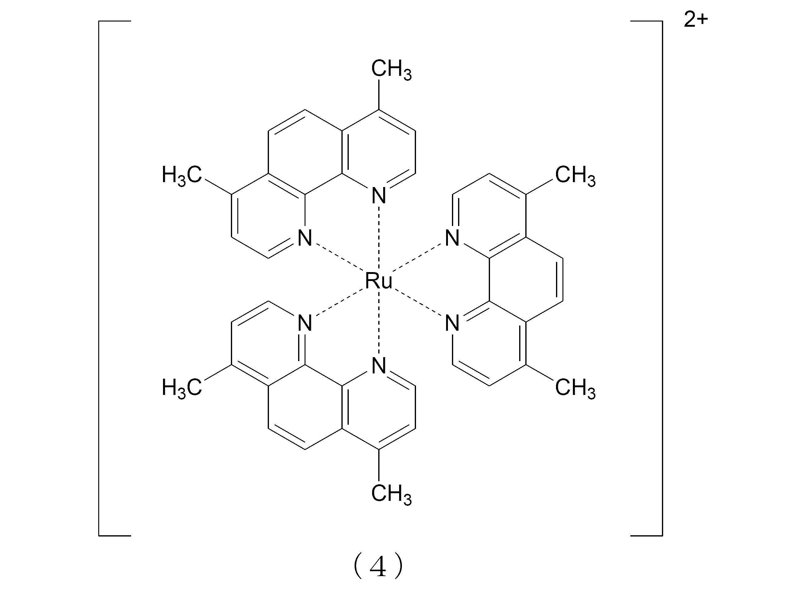

- 前記水の酸化触媒が、遷移金属酸化物またはオキソ錯体である請求項1から7のいずれか一項に記載の過酸化水素製造方法。
- 前記水の酸化触媒が、ルテニウムのオキソ錯体、マンガンのオキソ錯体、イリジウムのオキソ錯体、鉄のオキソ錯体、インジウムオキサイド、ルテニウムオキサイド、イリジウムオキサイド、酸化タングステン、およびバナジン酸ビスマスからなる群から選択される少なくとも一つである請求項1から8のいずれか一項に記載の過酸化水素製造方法。
- 前記水の酸化触媒が、イリジウムオキサイドである請求項1から8のいずれか一項に記載の過酸化水素製造方法。
- 前記イリジウムオキサイドが、25℃で100mLの水に少なくとも1.5mg懸濁可能である請求項10に記載の過酸化水素製造方法。
- 前記過酸化水素発生工程において、前記反応系が、ルイス酸をさらに含む請求項1から11のいずれか一項に記載の過酸化水素製造方法。
- 前記過酸化水素発生工程において、前記反応系のpHが-2~10である請求項1から12のいずれか一項に記載の過酸化水素製造方法。
- 請求項1から13のいずれか一項に記載の過酸化水素製造方法に用いる前記遷移金属錯体と、前記水の酸化触媒とを含む過酸化水素製造用キット。
- 燃料容器と、燃料電池セルとを含む燃料電池であって、
前記燃料容器内に、請求項1から13のいずれか一項に記載の過酸化水素製造方法に用いる前記遷移金属錯体と、前記水の酸化触媒とを含むことを特徴とする燃料電池。
Priority Applications (2)
| Application Number | Priority Date | Filing Date | Title |
|---|---|---|---|
| JP2013522850A JP5700347B2 (ja) | 2011-06-25 | 2012-06-25 | 過酸化水素製造方法、過酸化水素製造用キットおよび燃料電池 |
| US14/129,001 US20140141346A1 (en) | 2011-06-25 | 2012-06-25 | Method for producing hydrogen peroxide, kit for producing hydrogen peroxide, and fuel battery |
Applications Claiming Priority (2)
| Application Number | Priority Date | Filing Date | Title |
|---|---|---|---|
| JP2011141280 | 2011-06-25 | ||
| JP2011-141280 | 2011-06-25 |
Publications (1)
| Publication Number | Publication Date |
|---|---|
| WO2013002188A1 true WO2013002188A1 (ja) | 2013-01-03 |
Family
ID=47424080
Family Applications (1)
| Application Number | Title | Priority Date | Filing Date |
|---|---|---|---|
| PCT/JP2012/066191 Ceased WO2013002188A1 (ja) | 2011-06-25 | 2012-06-25 | 過酸化水素製造方法、過酸化水素製造用キットおよび燃料電池 |
Country Status (3)
| Country | Link |
|---|---|
| US (1) | US20140141346A1 (ja) |
| JP (1) | JP5700347B2 (ja) |
| WO (1) | WO2013002188A1 (ja) |
Cited By (7)
| Publication number | Priority date | Publication date | Assignee | Title |
|---|---|---|---|---|
| JP2017039981A (ja) * | 2015-08-20 | 2017-02-23 | 国立研究開発法人産業技術総合研究所 | 過酸化水素の製造方法および製造装置 |
| JP2019037921A (ja) * | 2017-08-23 | 2019-03-14 | 国立研究開発法人物質・材料研究機構 | 固定化光触媒およびその製造方法 |
| WO2021059716A1 (ja) * | 2019-09-26 | 2021-04-01 | 学校法人早稲田大学 | 過酸化水素の製造法 |
| US11124414B2 (en) | 2016-10-20 | 2021-09-21 | Osaka University | Method for producing hydrogen peroxide, kit for hydrogen peroxide production, organic polymer photocatalyst used in said method and kit, and method for producing said organic polymer photocatalyst |
| CN114477097A (zh) * | 2022-01-12 | 2022-05-13 | 江南大学 | 基于卟啉基超分子的无牺牲剂光热催化产过氧化氢的方法 |
| CN116422318A (zh) * | 2023-04-21 | 2023-07-14 | 北京化工大学 | 氧化铟基催化剂及其在催化dmf制备n-甲酰基化合物中的应用 |
| CN116589054A (zh) * | 2023-05-10 | 2023-08-15 | 五邑大学 | 一种强化高铁酸盐去除水中有机污染物的方法 |
Families Citing this family (4)
| Publication number | Priority date | Publication date | Assignee | Title |
|---|---|---|---|---|
| JP6699171B2 (ja) * | 2013-10-02 | 2020-05-27 | 株式会社村田製作所 | 電池、電解質、電池パック、電子機器、電動車両、蓄電装置および電力システム |
| CN113620255B (zh) * | 2021-08-18 | 2022-09-20 | 华中科技大学 | 一种光催化系统及其应用 |
| CN115814818B (zh) * | 2022-11-17 | 2024-04-05 | 中南大学 | 一种复合半导体光催化材料及其制备方法和应用 |
| WO2024186959A2 (en) * | 2023-03-07 | 2024-09-12 | Gradiant Corporation | Generation of hydroxyl radicals in an advanced oxidation reactor |
Citations (4)
| Publication number | Priority date | Publication date | Assignee | Title |
|---|---|---|---|---|
| JPS58125602A (ja) * | 1982-01-20 | 1983-07-26 | Toshiba Corp | 水の分解方法 |
| JPS6414102A (en) * | 1987-05-05 | 1989-01-18 | Interox Sa | Manufacture of hydrogen peroxide |
| JPH09234374A (ja) * | 1996-02-29 | 1997-09-09 | Tokyo Gas Co Ltd | 水の光酸化触媒 |
| JP2010215938A (ja) * | 2009-03-13 | 2010-09-30 | Tokyo Institute Of Technology | 燃料電池型反応装置及びそれを用いた化合物の製造方法 |
Family Cites Families (1)
| Publication number | Priority date | Publication date | Assignee | Title |
|---|---|---|---|---|
| JP2009508676A (ja) * | 2005-09-15 | 2009-03-05 | バッテル メモリアル インスティテュート | 過酸化水素の光分解型発生 |
-
2012
- 2012-06-25 WO PCT/JP2012/066191 patent/WO2013002188A1/ja not_active Ceased
- 2012-06-25 JP JP2013522850A patent/JP5700347B2/ja not_active Expired - Fee Related
- 2012-06-25 US US14/129,001 patent/US20140141346A1/en not_active Abandoned
Patent Citations (4)
| Publication number | Priority date | Publication date | Assignee | Title |
|---|---|---|---|---|
| JPS58125602A (ja) * | 1982-01-20 | 1983-07-26 | Toshiba Corp | 水の分解方法 |
| JPS6414102A (en) * | 1987-05-05 | 1989-01-18 | Interox Sa | Manufacture of hydrogen peroxide |
| JPH09234374A (ja) * | 1996-02-29 | 1997-09-09 | Tokyo Gas Co Ltd | 水の光酸化触媒 |
| JP2010215938A (ja) * | 2009-03-13 | 2010-09-30 | Tokyo Institute Of Technology | 燃料電池型反応装置及びそれを用いた化合物の製造方法 |
Non-Patent Citations (3)
| Title |
|---|
| JIEUN JUNG ET AL.: "Yuki Cobalt Sakutai Shokubai o Mochiita Mizu o Denshigen to suru Sanso no Hikari Shokubai Kangen Hanno ni yoru Kasankasuiso no Sentakuteki Seisei", CSJ: THE CHEMICAL SOCIETY OF JAPAN KOEN YOKOSHU, vol. 92, no. 2, 9 March 2012 (2012-03-09), pages 359 * |
| SATOSHI KATO ET AL.: "Kashiko Shoshaka ni okeru Mizu o Denshigen to suru Sanso no Hikari Shokubaiteki Kangen ni yoru Sentakuteki Kasankasuiso Seisei", SYMPOSIUM ON PHOTOCHEMISTRY, vol. 2011, 1 September 2011 (2011-09-01), pages 46 * |
| SATOSHI KATO ET AL.: "Mizu o Denshigen to suru Sanso no Hikari Shokubaiteki Kangen ni yoru Sentakuteki Kasankasuiso Seisei Hanno ni okeru Lewis-san no Kasoku Koka", CSJ: THE CHEMICAL SOCIETY OF JAPAN KOEN YOKOSHU, vol. 92, no. 2, 9 March 2012 (2012-03-09), pages 370 * |
Cited By (9)
| Publication number | Priority date | Publication date | Assignee | Title |
|---|---|---|---|---|
| JP2017039981A (ja) * | 2015-08-20 | 2017-02-23 | 国立研究開発法人産業技術総合研究所 | 過酸化水素の製造方法および製造装置 |
| US11124414B2 (en) | 2016-10-20 | 2021-09-21 | Osaka University | Method for producing hydrogen peroxide, kit for hydrogen peroxide production, organic polymer photocatalyst used in said method and kit, and method for producing said organic polymer photocatalyst |
| JP2019037921A (ja) * | 2017-08-23 | 2019-03-14 | 国立研究開発法人物質・材料研究機構 | 固定化光触媒およびその製造方法 |
| WO2021059716A1 (ja) * | 2019-09-26 | 2021-04-01 | 学校法人早稲田大学 | 過酸化水素の製造法 |
| JP7599718B2 (ja) | 2019-09-26 | 2024-12-16 | 国際先端技術総合研究所株式会社 | 過酸化水素の製造法 |
| US12338123B2 (en) | 2019-09-26 | 2025-06-24 | International Frontier Technology Laboratory, Inc. | Hydrogen peroxide production method |
| CN114477097A (zh) * | 2022-01-12 | 2022-05-13 | 江南大学 | 基于卟啉基超分子的无牺牲剂光热催化产过氧化氢的方法 |
| CN116422318A (zh) * | 2023-04-21 | 2023-07-14 | 北京化工大学 | 氧化铟基催化剂及其在催化dmf制备n-甲酰基化合物中的应用 |
| CN116589054A (zh) * | 2023-05-10 | 2023-08-15 | 五邑大学 | 一种强化高铁酸盐去除水中有机污染物的方法 |
Also Published As
| Publication number | Publication date |
|---|---|
| US20140141346A1 (en) | 2014-05-22 |
| JP5700347B2 (ja) | 2015-04-15 |
| JPWO2013002188A1 (ja) | 2015-02-23 |
Similar Documents
| Publication | Publication Date | Title |
|---|---|---|
| JP5700347B2 (ja) | 過酸化水素製造方法、過酸化水素製造用キットおよび燃料電池 | |
| Miyoshi et al. | Water splitting on rutile TiO2‐based photocatalysts | |
| Oshima et al. | An artificial Z-scheme constructed from dye-sensitized metal oxide nanosheets for visible light-driven overall water splitting | |
| JP4572393B2 (ja) | ギ酸分解用触媒、ギ酸の分解方法、水素製造方法、ギ酸製造および分解用装置、水素貯蔵および発生方法 | |
| Zhou et al. | Facile synthesis of surface N-doped Bi2O2CO3: origin of visible light photocatalytic activity and in situ DRIFTS studies | |
| Zheng et al. | Selective photocatalytic oxidation of benzyl alcohol into benzaldehyde with high selectivity and conversion ratio over Bi4O5Br2 nanoflakes under blue LED irradiation | |
| Sun et al. | A dye-like ligand-based metal–organic framework for efficient photocatalytic hydrogen production from aqueous solution | |
| Zhang et al. | Novel La3+/Sm3+ co-doped Bi5O7I with efficient visible-light photocatalytic activity for advanced treatment of wastewater: Internal mechanism, TC degradation pathway, and toxicity analysis | |
| JP5165155B2 (ja) | 光半導体およびその製造方法、並びに、光半導体デバイス、光触媒、水素生成デバイスおよびエネルギーシステム | |
| Gultom et al. | Enhanced photocatalytic hydrogen production of noble-metal free Ni-doped Zn (O, S) in ethanol solution | |
| Liu et al. | Flower-like NiFe layered double hydroxide/Bi2WO6 S-scheme heterojunction for photodegradation of ciprofloxacin under visible light | |
| WO2012091045A1 (ja) | 光化学反応デバイス | |
| Cao et al. | Advances in two‐electron water oxidation reaction for hydrogen peroxide production: catalyst design and interface engineering | |
| El-Shishtawy et al. | An efficient visible-light-driven photoconversion of nitrobenzene to aniline over PtO-decorated WO3 nanocrystals prepared by a soft template-based method | |
| Tomita et al. | Mono-transition-metal-substituted polyoxometalates as shuttle redox mediator for Z-scheme water splitting under visible light | |
| Derikvand et al. | Photocatalytic degradation of organic pollutants under visible light using lead-free all-inorganic halide perovskites A3Bi2Cl9 (A= Cs, Rb) | |
| Bae et al. | Photocatalytic overall water splitting with dual-bed system under visible light irradiation | |
| Feng et al. | Ce-hydroxamate metal–organic frameworks for photocatalytic H 2 generation | |
| Tan et al. | Solar‐Driven Hydrogen Peroxide Production via BiVO4‐Based Photocatalysts | |
| JP6765132B2 (ja) | 過酸化水素製造方法、過酸化水素製造用キット並びにそれらに用いる有機高分子光触媒及びその製造方法 | |
| Tantraviwat et al. | Enhanced photoactivity and selectivity over BiOI-decorated Bi2WO6 microflower for selective oxidation of benzylamine: Role of BiOI and mechanism | |
| Hu et al. | New organic–inorganic hybrid compounds constructed from polyoxometalates and transition metal mixed-organic-ligand complexes | |
| Luo et al. | Water-soluble lanthanide–titanium–oxo cluster, a precursor for biocompatible nanomaterial | |
| Yang et al. | Construction of oxygen vacancy on Bi12O17Cl2 nanosheets by heat-treatment in H2O vapor for photocatalytic NO oxidation | |
| Zheng et al. | Enhanced photocatalytic activities of single-crystalline ZnGa 2 O 4 nanoprisms by the coexposed {111} and {110} facets |
Legal Events
| Date | Code | Title | Description |
|---|---|---|---|
| 121 | Ep: the epo has been informed by wipo that ep was designated in this application |
Ref document number: 12804606 Country of ref document: EP Kind code of ref document: A1 |
|
| DPE1 | Request for preliminary examination filed after expiration of 19th month from priority date (pct application filed from 20040101) | ||
| ENP | Entry into the national phase |
Ref document number: 2013522850 Country of ref document: JP Kind code of ref document: A |
|
| WWE | Wipo information: entry into national phase |
Ref document number: 14129001 Country of ref document: US |
|
| NENP | Non-entry into the national phase |
Ref country code: DE |
|
| 122 | Ep: pct application non-entry in european phase |
Ref document number: 12804606 Country of ref document: EP Kind code of ref document: A1 |