WO2013002175A1 - 反応液の粘度を検知する方法、反応液の粘度検知装置、反応生成物を得る方法及び反応生成物を得るための製造装置 - Google Patents
反応液の粘度を検知する方法、反応液の粘度検知装置、反応生成物を得る方法及び反応生成物を得るための製造装置 Download PDFInfo
- Publication number
- WO2013002175A1 WO2013002175A1 PCT/JP2012/066143 JP2012066143W WO2013002175A1 WO 2013002175 A1 WO2013002175 A1 WO 2013002175A1 JP 2012066143 W JP2012066143 W JP 2012066143W WO 2013002175 A1 WO2013002175 A1 WO 2013002175A1
- Authority
- WO
- WIPO (PCT)
- Prior art keywords
- power
- motor
- loss
- reaction
- viscosity
- Prior art date
- Legal status (The legal status is an assumption and is not a legal conclusion. Google has not performed a legal analysis and makes no representation as to the accuracy of the status listed.)
- Ceased
Links
Images



Classifications
-
- G—PHYSICS
- G01—MEASURING; TESTING
- G01N—INVESTIGATING OR ANALYSING MATERIALS BY DETERMINING THEIR CHEMICAL OR PHYSICAL PROPERTIES
- G01N11/00—Investigating flow properties of materials, e.g. viscosity, plasticity; Analysing materials by determining flow properties
- G01N11/10—Investigating flow properties of materials, e.g. viscosity, plasticity; Analysing materials by determining flow properties by moving a body within the material
- G01N11/14—Investigating flow properties of materials, e.g. viscosity, plasticity; Analysing materials by determining flow properties by moving a body within the material by using rotary bodies, e.g. vane
- G01N11/142—Sample held between two members substantially perpendicular to axis of rotation, e.g. parallel plate viscometer
-
- G—PHYSICS
- G01—MEASURING; TESTING
- G01N—INVESTIGATING OR ANALYSING MATERIALS BY DETERMINING THEIR CHEMICAL OR PHYSICAL PROPERTIES
- G01N11/00—Investigating flow properties of materials, e.g. viscosity, plasticity; Analysing materials by determining flow properties
- G01N11/10—Investigating flow properties of materials, e.g. viscosity, plasticity; Analysing materials by determining flow properties by moving a body within the material
- G01N11/14—Investigating flow properties of materials, e.g. viscosity, plasticity; Analysing materials by determining flow properties by moving a body within the material by using rotary bodies, e.g. vane
-
- G—PHYSICS
- G01—MEASURING; TESTING
- G01P—MEASURING LINEAR OR ANGULAR SPEED, ACCELERATION, DECELERATION, OR SHOCK; INDICATING PRESENCE, ABSENCE, OR DIRECTION, OF MOVEMENT
- G01P3/00—Measuring linear or angular speed; Measuring differences of linear or angular speeds
- G01P3/26—Devices characterised by the use of fluids
-
- G—PHYSICS
- G01—MEASURING; TESTING
- G01P—MEASURING LINEAR OR ANGULAR SPEED, ACCELERATION, DECELERATION, OR SHOCK; INDICATING PRESENCE, ABSENCE, OR DIRECTION, OF MOVEMENT
- G01P3/00—Measuring linear or angular speed; Measuring differences of linear or angular speeds
- G01P3/42—Devices characterised by the use of electric or magnetic means
- G01P3/44—Devices characterised by the use of electric or magnetic means for measuring angular speed
-
- G—PHYSICS
- G01—MEASURING; TESTING
- G01N—INVESTIGATING OR ANALYSING MATERIALS BY DETERMINING THEIR CHEMICAL OR PHYSICAL PROPERTIES
- G01N11/00—Investigating flow properties of materials, e.g. viscosity, plasticity; Analysing materials by determining flow properties
- G01N2011/0046—In situ measurement during mixing process
- G01N2011/0053—In situ measurement during mixing process using ergometry; measuring power consumption
Definitions
- the present invention relates to a method for detecting the viscosity of a reaction liquid using an induction motor as a power source, a reaction liquid viscosity detection apparatus, a method for obtaining a reaction product, and a manufacturing apparatus for obtaining a reaction product.
- the present inventors have proposed a reaction liquid viscosity detection device installed in a reactor that stirs a reaction liquid by rotating a stirring blade using an induction motor driven by an inverter as a power source (Patent Document 1). ).
- This detection apparatus has the following means 1) to 5), and is based on input power (P I ), loss power (P L ), and angular velocity ( ⁇ ) obtained from values measured by each measuring instrument.
- a power measuring instrument that measures the power supplied to the motor 2) A current measuring instrument that measures the current supplied to the motor 3) A voltage measuring instrument that measures the voltage supplied to the motor 4) Rotation of the motor Rotational speed measuring instrument that measures shaft speed 5) Frequency measuring instrument that measures inverter output frequency
- the devices for measuring the rotational speed used in 4) are contact type (mechanical type) and non-contact type (optical type, electromagnetic type) depending on the measurement method, and digital type and analog type depending on the processing method of the measurement signal.
- contact type mechanical type
- non-contact type optical type, electromagnetic type
- digital type and analog type depending on the processing method of the measurement signal.
- explosion-proof type Depending on the type and location of use, it is classified into an explosion-proof type and a non-explosion-proof type, both of which are known as conventional devices.
- the use of explosion-proof measuring instruments is obligatory at the production sites for resins such as urethane, varnish, and phenol produced by chemical reactions.
- rotational speed measuring instruments include a digital handy tachometer (Ono Sokki HT-5500) that combines contact and non-contact types, a visible light type tachometer (Hioki FT3405), and an electromagnetic rotational measuring instrument. (Hioki Electric MP-200), explosion-proof rotation measuring instrument (Ono Sokki RP-200), etc. are common, and these instruments can be selected with high accuracy and safety depending on the application. It can be used.
- rotational speed measuring instruments have a wide range of uses, but are used, for example, to measure the rotational speed of the output shaft of an electric motor.
- the viscosity detection of Patent Document 1 can detect the rotational torque with high accuracy based on the measurement values obtained by the means 1) to 5), and as a result, the relative viscosity of the reaction liquid can be known with high accuracy.
- the viscosity detector of Patent Document 1 requires a measuring instrument as an entity to know the rotational speed.
- the rotational speed measuring instrument used in the factory that handles the reaction liquid needs to satisfy the explosion-proof standard. Rotational speed measuring instruments that meet the explosion-proof standards are expensive, and not only increase the installation cost of the viscometer, but also have a long delivery time, and there is a problem that it is difficult to spread due to production stoppage at the time of installation. Therefore, it is desired to detect the rotation speed of the electric motor without using a rotation speed measuring instrument.
- the present inventors discharged a large amount of by-products out of the reaction system without using the actual rotational speed detector or viscometer detector, and the reaction solution in the system was discharged. Even if the mass changes with time, it is possible to detect the viscosity in the step of obtaining the reaction product with high accuracy, and an object is to provide an efficient method for detecting the viscosity of the reaction liquid.
- an object of the present invention is to provide a reaction viscosity tester using the method for detecting the viscosity of the reaction solution.
- the present invention provides a method for producing a reaction solution using the method for detecting the viscosity of the reaction solution.
- the present invention provides an apparatus for producing a reaction solution using the method for detecting the viscosity of the reaction solution.
- the inventor has focused on the slip of an induction motor (hereinafter abbreviated as “motor”). That is, the slip S is specified by the rotational speed (synchronous speed) Ns of the rotating magnetic field and the rotational speed (actual rotational speed of the motor) N of the rotating magnetic field, as is well known.
- the slip S and the machine output PM are substantially proportional to the range of the rated machine output P 0 and the rated slip S 0 . Therefore, the rotational speed of the electric motor can be obtained by obtaining the slip S based on the relationship between the slip S and the machine output PM.
- the unit of the rotation speed is treated as the number of rotations min ⁇ 1 per minute.
- the machine output PM is an unknown value.
- the mechanical output PM is obtained by subtracting the loss power P L from the input power P I , and the rotation speed of the motor is necessary to obtain the loss power P L. That's why. Therefore, simply, the rotational speed of the electric motor cannot be obtained based on the relationship between the slip S and the machine output PM.
- the present inventor considered that the loss power P L is a component that does not depend on the rotation speed of the motor (hereinafter, sometimes referred to as “independent loss component A”) and a component that depends on the rotation speed of the motor (hereinafter, “ We focused on the fact that it can be divided into two categories, sometimes referred to as “dependent loss component B”. Then, an approximation of the mechanical output PM calculated only independent loss component A except dependent loss component B as the power loss P L, the rotational speed of the motor by applying the relationship between the slip S and the mechanical output PM is I thought I could find it.
- the loss power when the input power P is supplied is defined as P L
- the loss power P L is determined from the loss power A that does not depend on the rotation speed and the loss power B that depends on the rotation speed.
- the secondary approximation N 2 was obtained in the step III, Step IV and step V, repeated a predetermined number of times.
- the third-order approximate speed, the fourth-order approximate speed,..., The n-order approximate speed obtained in this way have high accuracy with respect to the actual motor speed (actual speed) according to the order.
- how many orders the approximate speed is obtained is determined by the purpose, and depending on the purpose, the secondary approximate speed may be sufficiently satisfied with respect to the actual rotational speed. As shown in the examples described later, it has been confirmed that the actual rotation speed is sufficiently reflected even in the second order approximate speed in the viscosity detection of the reaction liquid.
- the present invention is a method for detecting the viscosity of a reaction solution in a step of obtaining a reaction product from two or more raw materials in a system in which the mass of the reaction solution changes with time as the reaction proceeds.
- the step of obtaining the reaction product includes stirring of the reaction liquid by rotating a rotating shaft provided with a stirring blade by using an induction conductor as a power source, and the method for detecting the viscosity of the reaction liquid includes the following steps:
- the present invention provides a method for detecting the viscosity of a reaction solution.
- An induction motor in which loss power when input power P is supplied is P L , and the loss power P L includes loss power A that does not depend on the rotation speed and loss power B that depends on the rotation speed.
- the difference between the electric power P and the loss electric power A is regarded as a first-order approximate value PM 1 of the mechanical output of the induction motor, and the output PM 1 and the slip S known for the induction motor are detected.
- F (W) [where (W) is (W 0 ) or (W 1 )] is a data obtained by actually measuring the torque when the mass of the reaction solution is changed in the reaction system. This is a mathematical formula obtained by polynomial regression. ]
- the present invention is an apparatus for detecting the viscosity of a reaction solution, which is installed in a reactor that stirs a reaction solution by rotating a rotating shaft provided with a stirring blade using the induction motor as a power source,
- the device is An information acquisition unit for acquiring measurement information including power, current, voltage, voltage frequency, and reaction liquid mass supplied to the electric motor;
- An arithmetic processing unit for calculating the viscosity of the reaction solution based on the measurement information,
- the said arithmetic processing part provides the viscosity detection apparatus of the reaction liquid characterized by performing the process prescribed
- the present invention also relates to a method for obtaining a reaction product from two or more raw materials in a system in which the mass of the reaction solution changes with time as the reaction proceeds, and the method uses an induction conductor as a power source.
- a method for obtaining a reaction product characterized in that the method of detecting the viscosity of the reaction solution, which involves stirring the reaction solution by rotating a rotating shaft provided with a stirring blade, includes the following steps: It is. 1) An induction motor in which loss power when input power P is supplied is P L , and the loss power P L includes loss power A that does not depend on the rotation speed and loss power B that depends on the rotation speed.
- the difference between the electric power P and the loss electric power A is regarded as a first-order approximate value PM 1 of the mechanical output of the induction motor, and the output PM 1 and the slip S known for the induction motor are detected.
- N S is the motor constant
- F (W) [where (W) is (W 0 ) or (W 1 )] is a data obtained by actually measuring the torque when the mass of the reaction solution is changed in the reaction system. This is a mathematical formula obtained by polynomial regression. ]
- the present invention is a manufacturing apparatus for obtaining a reaction product from two or more kinds of raw materials in a system in which the mass of a reaction solution changes with time as the reaction proceeds, and the apparatus uses an induction motor as a power source.
- the reaction liquid is agitated by rotating a rotating shaft equipped with a stirring blade, and the apparatus also includes measurement information including power, current, voltage, voltage frequency, and reaction liquid mass supplied to the electric motor.
- An information acquisition unit to acquire;
- An arithmetic processing unit that calculates the viscosity of the reaction solution based on the measurement information, and the arithmetic processing unit executes the processing defined in 1), 2), and 3) described above.
- a production apparatus for obtaining a reaction product characterized by the above is provided.
- the present invention provides a reaction liquid viscosity detection device.
- the detection apparatus includes an information acquisition unit that acquires measurement information including power, current, voltage, and voltage frequency supplied to the electric motor, and an arithmetic processing unit that calculates a rotation speed based on the measurement information.
- This arithmetic processing unit executes each process of a rotational speed detection process including the processes defined in Step I, Step II, and Step III, a rotational torque detection process, and a viscosity detection process.
- the arithmetic processing unit can also perform the third approximate speed, the fourth approximate speed,..., The calculation for obtaining the nth approximate speed, the rotational torque detection process when using the nth approximate speed, and the viscosity detection process. Not too long.
- the present invention it is possible to detect the rotational speed with high accuracy without using the actual speed measuring instrument.
- the cost for producing the reaction liquid viscosity detecting device can be kept low, and the delivery time can be shortened.
- the viscosity can be detected with high accuracy, and the target reaction product can be detected.
- the process 1) in the method for detecting the viscosity of the reaction liquid of the present invention is a process for detecting the rotational speed of the rotary shaft provided with the stirring blades using the induction motor as a power source. This process includes the following steps I to III.
- NS is an electric motor constant called a synchronous speed.
- Step II A step of obtaining the loss power B 1 based on the primary approximate value N 1 obtained in Step I.
- a step of obtaining a second order approximate value N 2 N S (1 ⁇ S 2 ) (N S is a motor constant) of the rotation speed from the motor constant).
- the obtained N 2 is treated as a second order approximation of the detected rotational speed.
- step I [Slip S and machine output PM]
- the slip S is specified by the following equation (1), where N S is the synchronization speed and N is the rotation speed of the rotor (actual rotation speed of the induction motor).
- S (N S ⁇ N) / N S (1)
- equation (1 ′) is obtained.
- N N S (1-S) Formula (1 ′) That is, if the slip S can be specified, the rotational speed of the induction motor can be obtained. Therefore, the present inventor decided to use the slip S to obtain the rotation speed of the induction motor.
- the slip S is a basic characteristic provided with the induction motor.
- the loss P L of the induction motor the loss caused by Joule heat due to the electrical resistance of the stator winding
- the secondary copper loss is a loss caused by Joule heat due to the electrical resistance of the rotor winding.
- the iron loss is composed of hysteresis loss and eddy current loss, both of which are caused by the generation of a rotating magnetic field.
- the mechanical loss is a loss due to friction and air resistance caused by the rotation of the shaft
- the floating loss is an intrinsic loss determined by the induction machine and is treated as a constant. Losses other than stray loss can be obtained by calculation using the voltage, current, power supply frequency, rotation speed, and electric circuit constants during operation of the induction conductor (Patent Document 1, paragraph [0028] to [0040]). The elements of each loss are shown below.
- the primary approximation value S 1 of the slip is obtained by the following equation (5) by applying the above equation (2).
- the first approximate value N 1 of the rotational speed corresponding to the first approximate value S 1 of the slip can be obtained by the following expression (6).
- N S is the synchronous speed.
- N 1 N S (1-S 1 ) (6)
- step I of the present invention The above is description corresponding to step I of the present invention, and hereinafter, steps II and III of the present invention will be described.
- first order approximation value N 1 of the rotational speed obtained in step I by the use purpose can be handled as a detection result of the rotation speed.
- step II the primary approximate value B 1 of the dependent loss component corresponding to the primary approximate value N 1 of the rotational speed obtained in step I is obtained from a known relational expression obtained by analysis of an equivalent circuit of the induction motor by ⁇ ( N 1 )
- a second-order approximation value PM 2 of the machine output obtained by substituting the first-order approximation value B 1 of the non-dependent loss component A and the dependence loss component into the equation (3) is given by the following equation (7). It is done. Further, similarly to the first-order approximation process, the second-order approximation value N 2 of the rotation speed can be obtained through the equations (8) and (9). Although this secondary approximation value N 2 is a secondary approximation value B 1 , the dependence loss component is taken into consideration, and therefore, the accuracy with respect to the actual rotational speed is higher than that of the primary approximation value N 1 .
- the primary approximate speed is obtained in Step I
- the power loss depending on the rotational speed corresponding to the speed is obtained in Step II
- the secondary power is obtained by incorporating the power loss in the total power loss in Step III. Find approximate speed.
- n is an integer of 1 or more, and B 0 is considered to be zero.
- the process 2) in the method for detecting the viscosity of the reaction liquid of the present invention is a process for detecting the rotational torque of a stirring blade using an induction motor as a power source.
- the rotational torque T (P ⁇ P L ) / ⁇ Equation (10) Equation 10 assumes that there is no change in the volume of the reaction solution in the reaction system. Therefore, in a system in which the mass of the reaction solution changes greatly with the progress of the reaction, for example, a system in which phenol and formaldehyde are reacted to produce a phenol resin, a large amount of condensed water is generated.
- Equation 10 (P ⁇ P L ) / ⁇ ⁇ [F (W 0 ) / F (W 1 )] Equation (10-1)
- (W 0 ) represents the mass of the reaction liquid at the standard time in a predetermined production unit
- (W 1 ) represents the mass of the reaction liquid at the time of detecting the viscosity of the reaction liquid in the process 3) described later.
- F (W) [where (W) is (W 0 ) or (W 1 )] is a data obtained by actually measuring the torque when the mass of the reaction solution is changed in the reaction system. This is a mathematical formula obtained by polynomial regression. ]
- the function formula F (W) is a mathematical formula obtained by measuring (actually measuring) torque when the mass of the reaction solution is changed in the reaction system and performing polynomial regression on the data. If the regression accuracy is high, it is not necessary to limit to a polynomial. For example, an exponential function or a rational function may be used. In any case, this function formula generally takes the form as shown in FIG. 6, and the shape of the curve changes depending on the reaction vessel volume, the shape of the stirring blade, the viscosity of the liquid charged in the vessel, and the rotational speed. When collecting, the above conversion error can be minimized by using a liquid material that has the same or central value as the viscosity of the reaction liquid that is actually produced at the rotational speed of the stirring blade when it is actually produced. It can be held to the limit.
- Another method for obtaining the function formula F (W) is simulation based on flow analysis.
- the present inventors confirmed that when using the reaction vessel capacity, the size of the stirring blade shape, the viscosity of the liquid material, the rotation speed, etc. as input information, values very close to those actually measured can be obtained. Yes.
- analysis software known and commonly used software such as FLUENT (Ansys) or STAR-CD (CD Adapto) can be used.
- ⁇ ⁇ T / N (unit Pa ⁇ S)
- input power P is required to obtain the rotational torque T of the electric motor.
- an input power measurement value is used.
- a known power meter can be used for the measurement. The power meter needs to be used properly depending on the type of motor used. For example, if the motor is a single-phase circuit, a single-phase wattmeter, if it is a three-phase motor, a three-phase wattmeter. Use.
- the power loss P L includes primary copper loss ( ⁇ (primary current I 1 ) 2 ), eddy current loss ( ⁇ (primary voltage V) 2 ), hysteresis loss ( ⁇ (primary voltage V) 2 / ( Frequency f)), secondary copper loss ( ⁇ ⁇ (I 1 , V, ⁇ )), mechanical loss ( ⁇ (angular velocity ⁇ )) and floating loss (constant).
- independent loss component A (W) primary copper loss, eddy current loss, and hysteresis loss depend on measured values obtained from current measuring instruments that measure current, voltage measuring instruments that measure voltage, and frequency measuring instruments that measure inverter output frequency. Calculated. More specifically, it can be obtained by performing a predetermined calculation using a voltage value, a current value, and a frequency during rotation driving, and a circuit constant unique to the electric motor.
- the circuit constant can also be obtained from a test table provided by an electric motor manufacturer or from a measurement value obtained by a load test of the electric motor.
- the floating loss is provided as a value inherent to the motor (fixed loss (unit W)).
- the primary copper loss, eddy current loss, and hysteresis loss are each expressed by the following general formula.
- Primary copper loss Primary winding resistance x (Single phase current) 2 x
- Eddy current loss Eddy current loss during operation at rated voltage x (Measured value of single phase voltage / rated phase voltage) 2 (Unit: W)
- Hysteresis loss Hysteresis loss during operation at rated voltage and rated frequency x (single-phase voltage measurement value / rated phase voltage) 2 / (inverter output frequency measurement value / rated frequency) (unit: Hz).
- the secondary copper loss and the mechanical loss are components that depend on the rotation speed of the electric motor, and the above-described dependency loss component Bn can be used.
- the loss power P L includes only the independent loss component A, but after the second approximation, the loss power P L Includes dependent loss components B 1 , B 2 ... In addition to the independent loss component A.
- the dependent loss secondary copper loss which is a component B n and mechanical loss can also be obtained in addition to the above, the n-order approximate speed N n.
- the mechanical output PM is a value obtained by subtracting each loss power from the input power P.
- PM n P ⁇ (A + B (n ⁇ 1) ). Therefore, the rotational torque T of the motor is determined by the equation (10) described above with reference also to n-order approximate rotational speed Nn described above, the rotational torque T n obtained can be determined as follows.
- T n PM n / (2 ⁇ ⁇ N n / 60) ⁇ F (Wo) / F (W 1 ) Equation (10-4)
- Equation (11) the force F generated when two planes of area A sandwiching a liquid of thickness h move at a relative speed U is expressed by the following equation (12 ).
- F ⁇ AU / h (unit N) (12)
- Step IV of determining the loss power B n based on the nth order approximate value N n as the rotational speed detection process
- the (n + 1) th order approximate value PM (n + 1) of the output of the motor is regarded as P ⁇ (A + B n )
- PM (n + 1) ⁇ S (n + 1) ( ⁇ is a motor constant) between the known output PM (n + 1) and the slip S (n + 1) for the motor, the (n + 1) th order approximate value N (n + 1 ) of the rotational speed.
- N S (1 ⁇ S (n + 1) ) (where N S is a motor constant) and step V (where n is an integer of 2 or more), After the secondary approximation N 2 was obtained in the step III, it is preferable to use a rotational speed Kenchi process repeated a predetermined number of times. Then, using the (n + 1) th order approximate value N (n + 1) obtained in this way, B 1 ⁇ B n and N ⁇ N (n + 1) are replaced in the equation (10-2) to obtain the rotational torque T. What is necessary is just to obtain
- the output frequency may be measured synchronously with other measurement quantities such as power, voltage, current, etc., and incorporated in various variables for determining the loss.
- the output frequency may be measured synchronously with other measurement quantities such as power, voltage, current, etc., and incorporated in various variables for determining the loss.
- a frequency measurement value for detecting the inverter output frequency into the hysteresis loss detection, it is possible to reduce the variation (variation) in the detected reaction liquid viscosity. This is preferable.
- the method for detecting the viscosity of the reaction solution and the method for obtaining the reaction product according to the present embodiment described above can detect the viscosity with high accuracy even in a reaction system in which the volume (mass) of the reaction solution changes according to the progress of the reaction. Can do.
- the apparatus for detecting the viscosity of the reaction liquid of the present invention is installed in a reactor that stirs the reaction liquid by rotating a rotating shaft equipped with a stirring blade using the induction motor as a power source, and detects the viscosity of the reaction liquid.
- the apparatus is an information acquisition unit that acquires measurement information including power, current, voltage, voltage frequency, and reaction liquid mass supplied to the electric motor, and based on the measurement information, A calculation processing unit that calculates the viscosity of the reaction solution by calculation, and the calculation processing unit executes the processing defined in 1), 2), and 3) according to claim 1 It is an apparatus having a liquid viscosity detecting device.
- the reaction product production apparatus of the present invention is a production apparatus for obtaining a reaction product from two or more raw materials in a system in which the mass of the reaction solution changes with time as the reaction proceeds.
- the apparatus stirs the reaction liquid by rotating a rotating shaft equipped with a stirring blade using an induction motor as a power source, and the apparatus supplies power, current, voltage, voltage frequency, and the like supplied to the motor.
- requires the viscosity of the said reaction liquid by calculation based on the said measurement information,
- the said arithmetic processing part is Claim 1. 1), 2) and 3), and a production apparatus for obtaining a reaction product.
- These manufacturing apparatuses include, for example, a power measuring instrument that measures power supplied to the motor, a current measuring instrument that measures current, a voltage measuring instrument that measures voltage, and a frequency measuring instrument that measures inverter output frequency. Is provided.
- the arithmetic processing part which calculates
- each measuring instrument for power, voltage, current, and frequency a known and commonly used measuring instrument can be used.
- arithmetic processing unit various types of personal computers such as notebook computers and desktop computers, or means having a known and commonly used arithmetic processing function such as a process computer can be used. Between these arithmetic processing units and the respective measuring instruments, there may be a publicly known and commonly used data communication function such as RS-232C, GP-IP, USB, ISA, PCI, and the above-mentioned synchronization signal generating means is a computer. It may be substituted by an instruction from the etc.
- the method for detecting the viscosity of the reaction liquid of the present invention and the method for obtaining the reaction product are the detection of the viscosity of the solution in which the mass of the reaction liquid changes in the course of the reaction and the reaction system in which the mass of the reaction liquid changes in the course of the reaction. Is preferably applied to a method for obtaining a reaction product. Examples of such a reaction system include a system for producing a phenol resin.
- the phenol resin is obtained by reacting phenols (F) and aldehydes (P). Usually, when the phenols (F) and the aldehydes (P) are reacted, for example, when producing a novolak type phenol resin, the molar ratio [(F) / (P)] is 0.5 to 1. Phenols (F) and aldehydes (P) are charged into the reaction system so as to be 0, and are reacted using an acidic catalyst.
- phenols (F) and aldehydes (P) are charged into the reaction system so that the molar ratio [(F) / (P)] is 1 to 3, The reaction is carried out using a sex catalyst.
- phenols examples include monohydric phenols, polyhydric phenols, and soluble lignocellulose materials.
- examples of the monohydric phenol include phenol; alkylphenols such as o-cresol, m-cresol, p-cresol, ethylphenol, iso-propylphenol, xylenol, 3,5-xylenol, butylphenol, t-butylphenol, nonylphenol; -Fluorophenol, m-fluorophenol, p-fluorophenol, o-chlorophenol, m-chlorophenol, p-chlorophenol, o-bromophenol, m-bromophenol, p-bromophenol, o-iodophenol, m -Halogenated phenols such as iodophenol and p-iodophenol; aminophenols such as o-aminophenol, m-aminophenol and p-a
- polyhydric phenol examples include resorcin, alkylresorcin, pyrogallol, catechol, alkylcatechol, hydroquinone, alkylhydroquinone, phloroglucin, bisphenol A, bisphenol F, bisphenol S, dihydroxynaphthalene and the like.
- soluble lignocellulosic material examples include a solution-like or paste-like material obtained by heating reaction of a lignocellulose material with monohydric phenol and / or polyhydric phenol.
- lignocellulose materials include plant fiber materials such as sawdust, wood flour, wood chips, veneer scraps, plywood scraps and bark; celluloses such as straw, rice straw, coffee bean residue, bagasse squeeze residue, beet pulp
- plant fiber materials such as sawdust, wood flour, wood chips, veneer scraps, plywood scraps and bark
- celluloses such as straw, rice straw, coffee bean residue, bagasse squeeze residue, beet pulp
- plant-derived materials mainly containing lignins and the like.
- aldehydes examples include aldehydes and compounds that generate aldehydes upon decomposition, such as formalin, formaldehyde, paraformaldehyde, trioxane, acetaldehyde, propionaldehyde, polyoxymethylene, chloral, hexamethylenetetramine, furfural, glyoxal, n- Examples include butyraldehyde, caproaldehyde, allyl aldehyde, benzaldehyde, crotonaldehyde, acrolein, tetraoxymethylene, phenylacetaldehyde, o-tolualdehyde, and salicylaldehyde.
- formalin formaldehyde
- paraformaldehyde Trihydroxyxane
- acetaldehyde propionaldehyde
- polyoxymethylene chloral
- hexamethylenetetramine furfural
- glyoxal
- the acidic catalyst examples include metal salt catalysts such as oxalic acid, sulfuric acid, hydrochloric acid, phosphoric acid, phenolsulfonic acid, paratoluenesulfonic acid, zinc acetate, and manganese acetate.
- Examples of the basic catalyst include alkali metal or alkaline earth metal hydroxides such as sodium hydroxide, potassium hydroxide and calcium hydroxide; carbonates such as sodium carbonate and calcium carbonate; oxides such as lime; Examples thereof include sulfites such as sodium; phosphates such as sodium phosphate; amines such as ammonia, trimethylamine, triethylamine, monoethanolamine, diethanolamine, triethanolamine, hexamethylenetetramine, and pyridine.
- alkali metal or alkaline earth metal hydroxides such as sodium hydroxide, potassium hydroxide and calcium hydroxide
- carbonates such as sodium carbonate and calcium carbonate
- oxides such as lime
- Examples thereof include sulfites such as sodium; phosphates such as sodium phosphate; amines such as ammonia, trimethylamine, triethylamine, monoethanolamine, diethanolamine, triethanolamine, hexamethylenetetramine, and pyridine.
- the phenol resin can be produced by performing heat polymerization with the phenols (F) and aldehydes (P) in the presence of an acidic catalyst or a basic catalyst.
- heat polymerization water is usually contained in the reaction system from the start of assembly. This water is water contained in aldehydes that are usually used.
- condensed water is generated by the reaction of phenols and aldehydes.
- the polymerization proceeds while discharging these waters out of the system. Therefore, as described above, the mass of the reaction solution changes as the reaction proceeds.
- the phenol resin production process includes, for example, the first step (hereinafter simply referred to as the first step) in which heat polymerization with phenols and aldehydes is performed in the presence of an acidic catalyst or a basic catalyst, and the reduced pressure in the reaction vessel. Condensation reaction is promoted by discharging the generated moisture, unreacted substances, and other volatile components out of the system, and the condensed resin generated at that time is also discharged out of the system and removed to increase the viscosity of the resin in the system. Second step (hereinafter simply referred to as second step). There are also many phenolic resins produced only in the first step. Hereinafter, the manufacturing method which has a 1st process and a 2nd process is explained in full detail.
- Water is usually used as the solvent used in the phenol resin production process. If necessary, further methanol, ethanol, n-propanol, iso-propanol, n-butanol, iso-butanol, sec-butanol, t-butanol, n-amyl alcohol, iso-amyl alcohol, n-hexanol, methyl amyl Alcohols such as alcohol, 2-ethylbutynol, n-heptanol, n-octanol, trimethylnonyl alcohol, cyclohexanol, benzyl alcohol, furfuryl alcohol, tetrahydrofurfuryl alcohol, abiethyl alcohol, and secondary acetone alcohol; acetone, methyl Acetone, methyl ethyl ketone, methyl-n-propyl ketone, methyl-n-butyl ketone, methyl-iso-butyl ketone, die
- the resin manufacturing process is completed only by the first process as described above. Even when the manufacturing process is completed in the first process or when the process proceeds to the second process, the end point judgment of the first process is determined in advance by considering the resin application and performance in the container. Judgment can be made based on whether the value is reached. Even when to end the manufacturing process in the first step, even in the case of continued shift to the second step, the viscosity of the reaction solution in the first step is a method for detecting the viscosity of the reaction solution of the present invention, the W 0 And W 1 can be obtained by setting the same amount.
- the reaction temperature in the first step is usually 50 to 110 ° C., and the reaction time is 1 to 10 hours.
- the process proceeds to a second step of further increasing the viscosity by a condensation reaction while discharging moisture, unreacted substances and other volatile components out of the system by reducing the pressure in the reaction vessel.
- the reaction vessel is depressurized to discharge moisture, unreacted substances, and other volatile components contained in the raw material out of the system, The condensation reaction is promoted, and the condensed water generated at that time is also discharged out of the system and removed, and the process proceeds to the second step in which the resin in the system further thickens.
- the determination of the reaction end point in the second step can be made based on whether the resin viscosity in the container has reached a predetermined value in consideration of the resin application and performance.
- the present invention solves the above problems, and can accurately obtain the viscosity of the reaction solution even when the volume (mass) of the reaction solution changes in the course of the reaction.
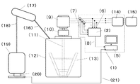
- the detection device 1 detects the rotational speed of a stirring blade 13 in which a liquid substance, for example, a chemical reaction product charged into the reaction kettle 12 is rotationally driven by an induction motor 9.
- the detection device 1 includes a measurement unit 2 and an arithmetic processing unit 5.
- the measuring unit 2 has four functions of a power meter, a voltmeter, an ammeter, and a frequency meter of a three-phase AC circuit.
- Many commercially available measuring instruments are packaged as one unit, and are connected to a three-phase AC circuit by a voltage lead-in line 6 and a current lead-in line 7.
- each measuring device may be provided in the measurement part separately.
- FIG. 3 assumes that the induction motor 9 that is a power source of the stirring blade 13 is a three-phase circuit, and that a known and commonly used three-phase wattmeter should be used. It goes without saying that both the voltage and current are measured for each phase, and the calculation for calculating the rotation speed is also performed for each phase. Further, the present invention can be similarly applied even when the target motor is a single-phase circuit or a DC motor driven by a DC power source.
- the arithmetic processing unit 5 is composed of, for example, a personal computer, controls the operation of the measuring unit, acquires the power value, the voltage value, the current value, and the frequency measured by the measuring unit 2 to obtain the above-described induction motor 9.
- the calculation process for obtaining the rotation speed and the rotation torque is performed, and the calculation process for obtaining the viscosity of the liquid material is performed based on the result.
- the arithmetic processing unit 5 holds information necessary for arithmetic processing such as a calculation process for obtaining the rotational speed, rotational torque, viscosity of the reaction liquid, and fixed loss of the induction motor 9, and the measurement information includes An operation for calculating the rotation speed is performed based on the result, and the result is output to a screen, an internal information recording means, or the like.
- the induction motor 9 is connected to a stirring shaft 11 via a speed reducer 10, and a stirring blade 13 is attached to the stirring shaft 11.
- the stirring blade 13 is disposed in the reaction kettle 12 and stirs the reaction object charged into the reaction kettle 12 according to the rotation of the induction motor 9. Electric power is supplied to the induction motor 9 from the three-phase power supply 15 via the inverter 14. Note that power may be directly supplied from the three-phase power supply 15 to the induction motor 9 without using the inverter 14.
- the liquid substance put into the reaction vessel 12 is led to a reaction by-product generated as the reaction proceeds, for example, condensed water, led to the condenser 17 through the pipe 16 and further stored in the storage tank 19 through the pipe 18.
- the mass discharged out of the reaction kettle is measured by the mass measuring instrument 20, and the measurement information is sent to the arithmetic processing unit 5 through the communication cable 21.
- the reaction liquid mass W 1 at the time of detecting the viscosity of the reaction liquid is obtained by subtracting the mass measured by the mass measuring instrument 20 from the total mass of the liquid material charged into the reaction vessel 12.
- the operator can know the rotational speed value, the rotational torque value, and the viscosity of the reaction liquid displayed on the monitor screen of the arithmetic processing unit 5 in real time.
- the torque obtained by the equation (10-2) includes components (referred to as empty torque) that are generated such as mechanical friction of the speed reducer and the bearing even when the contents of the reaction kettle are empty. Therefore, by detecting in advance the empty torque at the stirring speed employed at the time of manufacture, this is treated as a constant, and the viscosity accuracy is further increased by subtracting the constant from the value of the detected torque when the viscosity is obtained by Equation (11). Can do. Since this can also be performed according to the procedure described in Patent Document 1, the reprinting here is omitted.
- reaction solution viscosity value is calculated based on the difference between the charge amounts of both. It is also possible to correct the preparation amount by correcting. The correction of the charged amount can also be performed in accordance with the procedure described in Patent Document 1, so that the reprinting here is omitted.
- the specifications of the induction motor 9 are as follows. Specification of three-phase induction motor (Y connection) Capacity: 15kW Rated speed: 1460 revolutions per minute (rated slip 0.0266) Rated voltage: 200V Rated current: 57A Rated frequency: 50Hz Number of poles: 4 Primary winding resistance: 0.0943 ⁇ Primary winding reactance: 0.725 ⁇ (at rated frequency) Secondary winding resistance: 0.0130 ⁇ Secondary winding reactance: 0.0320 ⁇ (at rated frequency) Resistance measurement reference temperature: 20 ° C.
- the raw material of the phenol resin was used in a proportion of 64 parts by weight of phenol and 74.8 parts by weight of 41.5% formalin.
- As the catalyst 1.41 parts by weight of 48% strength aqueous sodium hydroxide solution was used. Specific use amounts are phenol 4609.4 kg, 41.5% concentration formalin 5387.8 kg, 48% concentration sodium hydroxide aqueous solution 101.52 kg.
- the measurement unit 2 shown in FIG. 3 used in the example uses a remote measurement monitoring system 2300 (Hioki Electric).
- This measuring instrument incorporates four functions of a power meter, a voltmeter, an ammeter, and a frequency meter of a three-phase AC circuit into one unit by appropriately selecting a measuring module. Any other measuring instrument can be used as long as it has the same measuring function.
- the arithmetic processing unit (PC) 5 obtains data from the measuring unit 2 through communication means, performs a predetermined calculation to calculate the rotational speed and rotational torque, and sends a measurement timing signal to each measuring means all at once. Also serves as a synchronizing signal generating means.
- Each measuring means measures a predetermined number of times per unit time at the same time in response to a command from the arithmetic processing unit 5, and the arithmetic processing unit 5 takes in the average value to calculate the rotational speed, rotational torque, and viscosity.
- FIG. 4 shows the rotational speed (second-order approximate value N 2 “1” in the figure) and the actual rotational speed (“2” in the figure) obtained in the process 1) in the method for detecting the viscosity of the reaction solution of the present invention. ) Shows the rotation speed chart. From this figure, it can be seen that the rotational speed detected in the present embodiment has a small difference from the actual rotational speed and reflects the actual rotational speed.
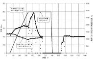
- FIG. 5 shows a viscosity chart in which the viscosity of the reaction liquid detected by applying the present invention, the viscosity of the reaction liquid detected by applying Patent Document 1, and a change (reduction) with time as the reaction proceeds.
- a chart of the measured mass is shown.
- the viscosity detected by the procedure of Patent Document 1 shows a decreasing tendency that does not match the actual situation from the time 120 minutes to 380 minutes, although the viscosity increase due to condensation actually occurs. Yes.
- the viscosity chart detected by applying the present invention since the change in the mass of the reaction liquid caused by the discharge is taken into consideration in the calculation of the torque performed in the previous stage, the value converted into the mass at a predetermined standard time is used. The detection result is always shown, and the detection result well matched to the actual situation is obtained by the effect.
- the notation of the viscosity unit in FIG. 5 uses rPa.S for the sake of convenience, with the prefix r added to distinguish it from what is output from a calibrated general viscometer.
- the relative viscosity represented by rPa.S is numerically unique to the stirring system composed of an electric motor, a speed reducer, and a stirring blade. Therefore, if the stirring system changes, the value increases or decreases as a whole. There is a thing. However, there is no problem in detecting the relative change in viscosity in the system.
- the rotational speed shown in FIG. 4 is a second order approximate value, but the rotational speed according to the present invention allows to obtain a value equal to or higher than the third order approximate value, and the rotational torque based on such a rotational speed, Allow to determine viscosity.
- the object further detected using the detected rotational speed is not limited to the viscosity of the reaction solution, and can be applied to any application.
- the reaction product liquid to be manufactured is not limited to the phenol resin, and it can be applied to the manufacture of any reaction liquid in which the mass of the reaction liquid changes with time as the reaction proceeds. .
Landscapes
- Physics & Mathematics (AREA)
- General Physics & Mathematics (AREA)
- Health & Medical Sciences (AREA)
- Life Sciences & Earth Sciences (AREA)
- Chemical & Material Sciences (AREA)
- Analytical Chemistry (AREA)
- Biochemistry (AREA)
- General Health & Medical Sciences (AREA)
- Immunology (AREA)
- Pathology (AREA)
- Control Of Ac Motors In General (AREA)
Abstract
Description
1)電動機に供給されている電力を計測する電力計測器
2)電動機に供給されている電流を計測する電流計測器
3)電動機に供給されている電圧を計測する電圧計測器
4)電動機の回転軸の速度を計測する回転速度計測器
5)インバータ出力周波数を計測する周波数計測器
前記損失電力A、前記知見1のステップIで得られた前記損失電力B1、及びステップIIIで得られた前記回転速度の二次近似値N2を基に、下記式
T=(P-(A+B1))/(2π×N2/60)
で回転トルクを求め、この回転トルクTから下記式
η=κT/N(単位Pa・S)
により粘度ηを求めることができる事を見出した(知見2)。
反応生成物を得る工程が誘導電導機を動力源として攪拌翼を供えた回転軸を回転することにより反応液の攪拌を含むものであり、反応液の粘度を検知する方法が以下の過程を含むことを特徴とする反応液の粘度を検知する方法を提供するものである。
1)投入電力Pが供給されているときの損失電力をPLとし、かつ、前記損失電力PLが回転速度に依存しない損失電力Aと回転速度に依存する損失電力Bとからなる、誘導電動機における回転速度を検知する過程であって、前記電力Pと前記損失電力Aの差分を前記誘導電動機の機械出力の一次近似値PM1とみなし、前記誘導電動機について既知である出力PM1とすべりS1との関係式PM1=κS1(κは電動機定数)から前記回転速度の一次近似値N1=NS(1-S1)(NSは電動機定数)を求めるステップIと、前記一次近似値N1に基づいて、前記損失電力B1を求めるステップIIと、前記電動機の出力の二次近似値PM2をP-(A+B1)とみなし、前記電動機について前記既知である出力PMとすべりSとの関係式PM2=κS2(κは電動機定数)から回転速度の二次近似値N2=NS(1-S2)(NSは電動機定数)を求めるステップIIIを含む回転速度検知過程。
2)前記投入電力P、前記損失電力A、前記回転速度検知過程のステップIで得られた前記損失電力B1、前記ステップIIIで得られた前記回転速度の二次近似値N2、及びトルクTと反応液の質量Wの関係を表す関数式T=F(W)を基に、下記式
T=(P-(A+B1))/(2π×N2/60)×F(W0)/F(W1)
〔(W0)は予め定められた製造単位における標準時の反応液の質量を表し、(W1)は当該反応液の粘度を検知する時点の反応液の質量を表す。また、F(W)〔ここで、(W)は(W0)または(W1)である〕は、当該反応系において、反応液の質量を変化させたときのトルクを実測し、そのデータに対して多項式回帰させた数式である。〕
により回転トルクTを求める回転トルク検知過程。
3)前記回転トルク検知過程で得られた回転トルクを基に、下記式
η=κT/N(単位Pa・S)
により粘度ηを求める粘度検知過程。
前記装置は、
前記電動機に供給されている電力、電流、電圧、電圧周波数、及び反応液質量を含む計測情報を取得する情報取得部と、
前記計測情報に基づいて、前記反応液の粘度を演算により求める演算処理部と、を備え、
前記演算処理部は、前記に記載の1)、2)及び3)で規定される処理を実行することを特徴とする反応液の粘度検知装置を提供するものである。
1)投入電力Pが供給されているときの損失電力をPLとし、かつ、前記損失電力PLが回転速度に依存しない損失電力Aと回転速度に依存する損失電力Bとからなる、誘導電動機における回転速度を検知する過程であって、前記電力Pと前記損失電力Aの差分を前記誘導電動機の機械出力の一次近似値PM1とみなし、前記誘導電動機について既知である出力PM1とすべりS1との関係式PM1=κS1(κは電動機定数)から前記回転速度の一次近似値N1=NS(1-S1)(NSは電動機定数)を求めるステップIと、前記一次近似値N1に基づいて、前記損失電力B1を求めるステップIIと、前記電動機の出力の二次近似値PM2をP-(A+B1)とみなし、前記電動機について前記既知である出力PMとすべりSとの関係式PM2=κS2(κは電動機定数)から回転速度の二次近似値N2=NS(1-S2)(NSは電動機定数)を求めるステップIIIを含む回転速度検知過程。
2)前記投入電力P、前記損失電力A、前記回転速度検知過程のステップIで得られた前記損失電力B1、前記ステップIIIで得られた前記回転速度の二次近似値N2、及びトルクTと反応液の質量Wの関係を表す関数式T=F(W)を基に、下記式
T=(P-(A+B1))/(2π×N2/60)×F(W0)/F(W1)
〔(W0)は予め定められた製造単位における標準時の反応液の質量を表し、(W1)は当該反応液の粘度を検知する時点の反応液の質量を表す。また、F(W)〔ここで、(W)は(W0)または(W1)である〕は、当該反応系において、反応液の質量を変化させたときのトルクを実測し、そのデータに対して多項式回帰させた数式である。〕
により回転トルクTを求める回転トルク検知過程。
3)前記回転トルク検知過程で得られた回転トルクを基に、下記式
η=κT/N(単位Pa・S)
により粘度ηを求める粘度検知過程。
前記計測情報に基づいて、前記反応液の粘度を演算により求める演算処理部と、を備え、 前記演算処理部は、前記に記載の1)、2)及び3)で規定される処理を実行する、
ことを特徴とする反応生成物を得る製造装置を提供するものである。
また三次近似速度、四次近似速度、…、n次近似速度を求めるための演算、n次近似速度を用いる場合の回転トルク検知過程、粘度検知過程もまた演算処理部が行うことができることはいうまでもない。
本発明の反応液の粘度を検知する方法における1)の過程は、誘導電動機を動力源として攪拌翼を供えた回転軸の回転速度を検知する過程である。この過程は以下のステップI~IIIの過程を含む。
ステップIII:前記電動機の出力の二次近似値PM2をP-(A+B1)とみなし、前記電動機について前記既知である出力PM2とすべりS2との関係式PM2=κS2(κは電動機定数)から回転速度の二次近似値N2=NS(1-S2)(NSは電動機定数)を求めるステップ。ここで、得られるN2が、検知された回転速度の二次近似値として扱われる。
[すべりSと機械出力PMについて]
すべりSは、よく知られているように、同期速度をNS、回転子の回転速度(誘導電動機の実回転速度)Nとすると、下記式(1)により特定される。
S=(NS―N)/NS …式(1)
なお、式(1)をNで解くと式(1')の通りである。
N=NS(1-S) …式(1')
つまり、すべりSが特定できれば、誘導電動機の回転速度を得ることができる。そこで、本発明者は誘導電動機の回転速度を求めるのにすべりSを利用することにした。なお、すべりSは誘導電動機に伴って提供される基本的な特性である。
この式(2)におけるκは誘導電動機に固有の定数であり、定格すべりS0に対する定格機械出力PM0の比PM0/S0として与えられる。
したがって、機械出力PMが判れば、すべりSが求められ、さらに回転速度(あるいは角速度)を求めることができる。
PM=κ×S …式(2)
PM=P-PL …式(3)
ここで、誘導電動機の損失PLは、一次銅損、二次銅損、鉄損、機械損、及び浮遊損からなることが知られている。そして、一次銅損は固定子巻線の電気抵抗によるジュール熱、二次銅損は回転子巻線の電気抵抗によるジュール熱、に起因してそれぞれ発生する損失である。また、鉄損はヒステリシ損と渦電流損とから成り何れも回転磁界発生に起因する損失である。さらに、機械損は軸の回転によって生ずる摩擦や空気抵抗に起因する損失であり、浮遊損は誘導電機によって決まる固有損失であり定数として扱われる。浮遊損以外の損失は、誘導電導機を運転している時の電圧、電流、電源周波数、回転速度、及び電導機回路定数を使って演算で求めることができる(特許文献1 段落[0028]~[0040])。なお、各損失の要素を以下に示しておく。
一次銅損:∝ (一次電流I1)2
渦電流損:∝ (一次電圧V)2
ヒステリシス損:∝ (一次電圧V)2/(周波数f)
二次銅損:∝ (二次電流I2)2 → φ(I1,V,ω)
機械損:∝ (角速度ω)
浮遊損:一定
PM=P-(A+B) …式(3')
[依存損失成分B] 二次銅損,機械損
PM1=P-A …式(4)
こうして、機械出力(一次近似値)が求められたので、上記の式(2)を適用することによりすべりの一次近似値S1は下記の式(5)により求められる。
S1=PM1/κ=PM1×S0/P0 …式(5)
さらに式(1')を適用することにより、下記の式(6)により、すべりの一次近似値S1に対応する回転速度の一次近似値N1を求めることができるのである。ここで、NSは同期速度である。
N1=NS(1-S1) …式(6)
S2=PM2/κ=PM2×S0/P0 …式(8)
N2=NS(1-S2) …式(9)
三次から四次に進む手順もステップII、ステップIIIを順次同様に繰り返すことで行うことができる。
本発明においては前記繰り返しの回数を多くするほど、損失電力PLの値が真の値に近づいていくことになるので、それによって得られる回転速度もより正確な値に近づいて行く。ただし、本発明は、次数を高くすることを必須な要件とするものではない。後述する実施例に示されるように、二次近似速度により、回転速度検知の目的を十分に達成することができる。
PMn=P-(A+B(n-1)) …n次近似機械出力
Nn=NS(1-Sn) …n次近似回転速度
Bn=φ(Nn) …n次近似依存損失成分
なお、以上の一般式のnは1以上の整数であり、B0はゼロと見做す。
T=(P-PL)/ω…式(10)
式10は、反応系内の反応液の容量に変化がないことを前提にしている。その為、反応の経過に伴い反応液の質量が大きく変化する系、例えば、フェノールとホルムアルデヒドとを反応させてフェノール樹脂を製造する系では、縮合水が大量に発生する。その為、フェノール樹脂の製造方法では、フェノールとホルムアルデヒドとの反応を進行させる間、生成する上記縮合水及び未反応物を、反応容器内の減圧等により反応系外へ排出しつつ、縮合反応によって更に生成物の増粘を図っている。このような場合、単に上記式(10)に基づいて前記攪拌翼のトルクを求めると、反応系内の容量が大きく減少している為、容器内の反応液の粘度が増加しているにも関わらず、攪拌翼の回転トルクは寧ろ低下することもある為、後述する3)過程の粘度過程において、得られる粘度の値が真の粘度よりも小さくなる問題がある。
T=(P-PL)/ω×〔F(W0)/F(W1)〕…式(10-1)
ここで、前記(W0)は予め定められた製造単位における標準時の反応液の質量を表し、(W1)は後述する3)過程で当該反応液の粘度を検知する時点の反応液の質量を表す。また、F(W)〔ここで、(W)は(W0)または(W1)である〕は、当該反応系において、反応液の質量を変化させたときのトルクを実測し、そのデータに対して多項式回帰させた数式である。〕
T=(P-(A+B1))/(2π×N2/60)×〔F(W0)/F(W1)〕…式(10-2)となる。
η=κT/N(単位Pa・S)
により粘度ηを求める粘度検知を検知する過程である。ここで、κは反応釜や攪拌翼等によって決まる比例定数である。尚、粘度の検知目的が相対的な変化(絶対値でなく)である場合はκ=1として扱ってもよい。
本実施形態において、電動機の回転トルクTを求めるために投入電力Pが必要である。
投入電力Pとしては、投入電力計測値を用いる。計測には公知の電力計測器を用いることができる。電力計測器は、用いられる電動機の種類によって、使い分けを行うことが必要で、例えば、電動機が単相回路である場合は単相用電力計、3相電動機である場合は3相用電力計を用いる。
また、誘導電動機の回転トルクTを求めるために損失電力PLが必要である。
損失電力PLは、前述したように、一次銅損(∝(一次電流I1)2)、渦電流損(∝ (一次電圧V)2)、ヒステリシス損(∝ (一次電圧V)2/(周波数f))、二次銅損(∝ φ(I1,V,ω))、機械損(∝ (角速度ω))及び浮遊損(一定)を含んでいる。
[非依存損失成分A(W)]
これらの中で、一次銅損、渦電流損及びヒステリシス損は、電流を計測する電流計測器、電圧を計測する電圧計測器及びインバータ出力周波数を計測するための周波数計測器から得られる計測値によって算出される。より具体的には、回転駆動中の電圧値、電流値及び周波数と、電動機に固有の回路定数を用い、所定演算を行うことにより求めることができる。ここで回路定数は、電動機メーカーから提供される試験表によっても、又は、電動機の負荷試験による計測値によっても得ることができる。また、浮遊損は、電動機に固有の値(固定損(単位W)として提供される。
一次銅損、渦電流損及びヒステリシス損は、各々以下の一般式で表される。
一次銅損=一次巻線抵抗×(一相電流)2×電動機の相数式
渦電流損=定格電圧で運転時の渦電流損×(一相電圧計測値/定格相電圧)2(単位W)
ヒステリシス損=定格電圧及び定格周波数で運転時のヒステリシス損×(一相電圧計測値/定格相電圧)2/(インバータ出力周波数計測値/定格周波数)(単位Hz)。
これに対して、二次銅損及び機械損は、電動機の回転速度に依存する成分であり、前述した依存損失成分Bnを用いることができる。ただし、一次近似回転速度N1を求める段階では依存損失成分Bnは得られていないので、損失電力PLは非依存損失成分Aだけを含むが、二次近似以降になると、損失電力PLは非依存損失成分Aに加えて依存損失成分B1、B2…を含むことになる。
依存損失成分Bnである二次銅損及び機械損については、以上の他に、n次近似回転速度Nnから求めることもできる。つまり、二次銅損及び機械損は角速度ωを変数としているところ、角速度ωは回転速度Nとω=2πN[rad/s]の関係にあるので、n次近似回転速度Nnを二次銅損及び機械損の各々関係式に代入すれば、二次銅損及び機械損を求めることができる。
機械出力PMは、投入電力Pから各損失電力を差し引いた値であるが、本実施形態では、前述のように、一般式:PMn=P-(A+B(n-1))で求められる。
従って、電動機の回転トルクTは、前述したn次近似回転速度Nnをも用いて前述した式(10)により求め、得られた回転トルクTnは以下のように求めることができる。
Tn=(P-PL)/ω=PMn/ωn=PMn/(2π×Nn/60) …式(10-3)
そこでトルクTと反応液の質量Wの関係を表わす関数式T=F(W)を導入し、標準生産質量Woのときの値に換算したものとするために、式(10-3)を改めて次のように書き直す。
ηn=κTn/Nn(単位Pa・S) …式(11)
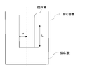
ニュートンの式によれば、厚さhの液体を間に挟んだ2枚の面積Aの平面が相対速度Uで運動する時発生する力Fは、ηが粘度を表すとして、以下の式(12)で表される。
F=ηAU/h(単位N) …式(12)
F=η(2πrL・2πrN)/g …式(13)
従って、
回転トルク(T)=F・r=η(2πrl・2πrN)/g・r(単位N・m)
であるので、
η=T・g/(2πrl・2πrN・r)となる。
しかるに、T、N以外は反応容器及び撹拌翼の寸法によって決定される定数なので改めて、粘度ηは式(11)のように表され、本実施形態により、相対的に液状物の粘度を求めることができる。
η=κT/N …式(11)
前記電動機について前記既知である出力PM(n+1)とすべりS(n+1)との関係式PM(n+1)=κS(n+1)(κは電動機定数)から回転速度の(n+1)次近似値N(n+1)=NS(1-S(n+1))(NSは電動機定数)を求めるステップVとを(ただし、nは2以上の整数)、
前記ステップIIIで前記二次近似値N2が得られた後に、予め定められた回数だけ繰り返す回転速度検値過程を用いるのが好ましい。そして、このようにして求めた(n+1)次近似値N(n+1)を用い式(10-2)においてB1→Bn、N→N(n+1)の置き換えを行って回転トルクTを求め、更にその値を式(11)に代入して求めればよい。
本実施形態において、負荷の時間変動が速い場合は、各計測器における計測タイミングのズレがエネルギーの入出力の総和がゼロになるというエネルギー保存則の前提を崩してしまうため、各計測器における計測は同期的に行われることが望ましい。但し、負荷の変動が緩やかであって、全ての計測値を採取し終えるまでの間に計測値が実質的に変化しないと言えるような場合はこの限りではない。
さらに負荷の時間変動が激しい場合には、計測器の他に、各計測器に対して一斉に計測指令を出すための同期信号発生手段が設けられて、各計測器による計測が同期的に行われるようにすることもできる。
検知装置1は、反応釜12内に投入された液状物、例えば化学反応製品を誘導電動機9により回転駆動される撹拌翼13の回転速度を検知するものである。
計測部2は、三相交流回路の電力計、電圧計、電流計及び周波数計の4つの機能を有する。市販される計測器は、これらが一つのユニットとしてパッケージ化されたものが多く、電圧引き込み線6及び電流引き込み線7により三相交流回路と接続されている。尚、計測部は各計測器が個別に設けられていてもよいことはいうまでもない。
ところで、一次銅損を求める際に巻線抵抗の値を用いるが、巻線抵抗は、通常基準温度(20℃)での値が提供される。したがって、一次銅損を求めるにあたっては、実際の運転温度で補正した値を用いると回転速度、ひいては回転トルク及び反応液の粘度の検知精度をより高めることができる。この温度補正については、特許文献1に記載された手順に準じて行えばよいので、ここでの再掲は省略する。
式(10-2)によって求められるトルクは、反応釜の内容物が空の場合であっても減速機や軸受けの機械摩擦など発生している成分(空トルク、と称す)を含む。そこで製造時に採用する攪拌速度における空トルクを予め検知しておいてこれを定数扱いとし、式(11)で粘度を求める際に検知トルクの値から当該定数を差し引くことで粘度精度をより高めることができる。これについても特許文献1に記載された手順に準じて行えるので、ここの再掲は省略する。
一般に反応温度は製品毎によって決められるので反応釜には温度制御機能が備えられる。温度制御誤差の粘度影響が無視できる場合にはこの補正は不要であるが現実には±1~3℃程度の誤差は避けられないので、予め定められる温度(標準反応温度)での値に補正した値を用いると検知精度を高めることができる。これについても特許文献1に記載された手順に準じて行えるので、ここの再掲は省略する。
また、本実施形態において、予め定められた反応釜での製造単位あたりの標準仕込み量と、当該製造単位における実仕込み量が異なる場合に、両者の仕込み量の差に基づいて反応液粘度値を補正することによる仕込み量の補正を行うこともできる。この仕込み量の補正についても、特許文献1に記載された手順に準じて行えるので、ここでの再掲は省略する。
三相誘導電動機(Y結線)の仕様
容量:15kW 定格速度:毎分1460回転(定格すべり0.0266)
定格電圧:200V 定格電流:57A 定格周波数:50Hz
極数:4
一次巻線抵抗:0.0943Ω
一次巻線リアクタンス:0.725Ω(定格周波数時)
二次巻線抵抗:0.0130Ω
二次巻線リアクタンス:0.0320Ω(定格周波数時)
抵抗計測基準温度:20℃ 抵抗温度係数:234.5
機械損:70W(定格速度時)
鉄損:335W(設計値:ヒステリシス損115W、渦電流損120W)
浮遊損:132W 撹拌軸減速比:17:1
演算処理部(PC)5は、計測部2から通信手段を通じてデータを入手し、所定演算を行って回転速度、回転トルクを算出する演算機能と、各計測手段に対して一斉に計測タイミング信号を発する同期信号発生手段を兼ねる。各計測手段は演算処理部5からの指令で一斉に、単位時間あたり所定回数の計測を行い、その平均値を演算処理部5が取り込んで回転速度、回転トルク、粘度を算出する。
具体的には T = 0.000,000,003*W3-0.000,084,8*W2-0.919,3*W-2,140.9である。
尚、この関数式において、仕込み量が基準値(Wo=10,097kg)である時の基準トルクToは1,255Nmである。
つまり、図4に示される回転速度は二次近似値であるが、本発明による回転速度は三次近似値以上の値まで求めることを許容し、また、そのような回転速度に基づいて回転トルク、粘度を求めることを許容する。
次に、検知された回転速度(回転トルク)を用いてさらに検知される対象は、反応液の粘度に限るものではなく、いかなる用途に適用することもできる。
更に、製造の対象とする反応生成液もフェノール樹脂に限定されるものでなく、反応の進行に伴い反応液の質量が経時的に変化する、いかなる反応液の製造にも適用することを許容する。
2 計測部
5 演算処理部
9 誘導電動機
12 反応釜
13 撹拌翼
14 インバータ
15 三相電源
19 貯蔵タンク
20 質量計測器
Claims (9)
- 反応液の質量が反応の進行に伴い経時的に変化する系内で、2種以上の原料から反応生成物を得る工程における反応液の粘度を検知する方法であって、
反応生成物を得る工程が誘導電導機を動力源として攪拌翼を供えた回転軸を回転することにより反応液の攪拌を含むものであり、反応液の粘度を検知する方法が以下の過程を含むことを特徴とする反応液の粘度を検知する方法。
1)投入電力Pが供給されているときの損失電力をPLとし、かつ、前記損失電力PLが回転速度に依存しない損失電力Aと回転速度に依存する損失電力Bとからなる、誘導電動機における回転速度を検知する過程であって、前記電力Pと前記損失電力Aの差分を前記誘導電動機の機械出力の一次近似値PM1とみなし、前記誘導電動機について既知である出力PM1とすべりS1との関係式PM1=κS1(κは電動機定数)から前記回転速度の一次近似値N1=NS(1-S1)(NSは電動機定数)を求めるステップIと、
前記一次近似値N1に基づいて、前記損失電力B1を求めるステップIIと、
前記電動機の出力の二次近似値PM2をP-(A+B1)とみなし、前記電動機について前記既知である出力PM2とすべりS2との関係式PM2=κS2(κは電動機定数)から回転速度の二次近似値N2=NS(1-S2)(NSは電動機定数)を求めるステップIIIを含む回転速度検知過程。
2)前記投入電力P、前記損失電力A、前記回転速度検知過程のステップIで得られた前記損失電力B1、前記ステップIIIで得られた前記回転速度の二次近似値N2、及びトルクTと反応液の質量Wの関係を表す関数式T=F(W)を基に、下記式
T=(P-(A+B1))/(2π×N2/60)×F(W0)/F(W1)
〔(W0)は予め定められた製造単位における標準時の反応液の質量を表し、(W1)は当該反応液の粘度を検知する時点の反応液の質量を表す。また、F(W)〔ここで、(W)は(W0)または(W1)である〕は、当該反応系において、反応液の質量を変化させたときのトルクを実測し、そのデータに対して多項式回帰させた数式である。〕
により回転トルクTを求める回転トルク検知過程。
3)前記回転トルク検知過程で得られた回転トルクを基に、下記式
η=κT/N(単位Pa・S)
により粘度ηを求める粘度検知過程。 - 前記1)回転速度検知過程として、n次近似値Nnに基づいて損失電力Bnを求めるステップIVと、前記電動機の出力の(n+1)次近似値PM(n+1)をP-(A+Bn)とみなし、
前記電動機について前記既知である出力PM(n+1)とすべりS(n+1)との関係式PM(n+1)=κS(n+1)(κは電動機定数)から回転速度の(n+1)次近似値N(n+1)=NS(1-S(n+1))(NSは電動機定数)を求めるステップVとを(ただし、nは2以上の整数)、
前記ステップIIIで前記二次近似値N2が得られた後に、予め定められた回数だけ繰り返す回転速度検地過程を用いる、請求項1に記載の反応液の粘度を検知する方法。 - 反応液の質量が反応の進行に伴い経時的に変化する系内で、2種以上の原料から反応生成物を得る工程における反応液の粘度を検知する方法であって、反応生成物を得る工程が誘導電導機を動力源として攪拌翼を供えた回転軸を回転することにより反応液の攪拌を含むものであり、反応液の粘度を検知する方法が以下の過程を含むことを特徴とする反応液の粘度を検知する装置において、
前記装置は、
前記電動機に供給されている電力、電流、電圧、電圧周波数、及び反応液質量を含む計測情報を取得する情報取得部と、
前記計測情報に基づいて、前記反応液の粘度を演算により求める演算処理部と、を備え、
前記演算処理部は、1)投入電力Pが供給されているときの損失電力をPLとし、かつ、前記損失電力PLが回転速度に依存しない損失電力Aと回転速度に依存する損失電力Bとからなる、誘導電動機における回転速度を検知する過程であって、前記電力Pと前記損失電力Aの差分を前記誘導電動機の機械出力の一次近似値PM1とみなし、前記誘導電動機について既知である出力PM1とすべりS1との関係式PM1=κS1(κは電動機定数)から前記回転速度の一次近似値N1=NS(1-S1)(NSは電動機定数)を求めるステップIと、
前記一次近似値N1に基づいて、前記損失電力B1を求めるステップIIと、
前記電動機の出力の二次近似値PM2をP-(A+B1)とみなし、前記電動機について前記既知である出力PM2とすべりS2との関係式PM2=κS2(κは電動機定数)から回転速度の二次近似値N2=NS(1-S2)(NSは電動機定数)を求めるステップIIIを含む回転速度検知過程、
2)前記投入電力P、前記損失電力A、前記回転速度検知過程のステップIで得られた前記損失電力B1、前記ステップIIIで得られた前記回転速度の二次近似値N2、及びトルクTと反応液の質量Wの関係を表す関数式T=F(W)を基に、下記式
T=(P-(A+B1))/(2π×N2/60)×F(W0)/F(W1)
〔(W0)は予め定められた製造単位における標準時の反応液の質量を表し、(W1)は当該反応液の粘度を検知する時点の反応液の質量を表す。また、F(W)〔ここで、(W)は(W0)または(W1)である〕は、当該反応系において、反応液の質量を変化させたときのトルクを実測し、そのデータに対して多項式回帰させた数式である。〕
により回転トルクTを求める回転トルク検知過程、
3)前記回転トルク検知過程で得られた回転トルクを基に、下記式
η=κT/N(単位Pa・S)
により粘度ηを求める粘度検知過程、
で規定される処理を実行することを特徴とする反応液の粘度検知装置。 - 前記演算処理部は、
前記1)で規定される処理を実行する際に、ステップI~IIIに加えn次近似値Nnに基づいて損失電力Bnを求めるステップIVと、
前記電動機の出力の(n+1)次近似値PM(n+1)をP-(A+Bn)とみなし、
前記電動機について前記既知である出力PM(n+1)とすべりS(n+1)との関係式PM(n+1)=κS(n+1)(κは電動機定数)から回転速度の(n+1)次近似値N(n+1)=NS(1-S(n+1))(NSは電動機定数)を求めるステップVとを(ただし、nは2以上の整数)、
前記ステップIIIで前記二次近似値N2が得られた後に、予め定められた回数だけ繰り返す処理を実行する、請求項3に記載の反応液の粘度検知装置。 - 反応液の質量が反応の進行に伴い経時的に変化する系内で、2種以上の原料から反応生成物を得る方法であって、該方法は誘導電導機を動力源として攪拌翼を供えた回転軸を回転することにより反応液の攪拌を伴い、しかも反応液の粘度を検知する方法が以下の過程を含むことを特徴とする反応生成物を得る方法。
1)投入電力Pが供給されているときの損失電力をPLとし、かつ、前記損失電力PLが回転速度に依存しない損失電力Aと回転速度に依存する損失電力Bとからなる、誘導電動機における回転速度を検知する過程であって、前記電力Pと前記損失電力Aの差分を前記誘導電動機の機械出力の一次近似値PM1とみなし、前記誘導電動機について既知である出力PMとすべりSとの関係式PM1=κS1(κは電動機定数)から前記回転速度の一次近似値N1=NS(1-S1)(NSは電動機定数)を求めるステップIと、
前記一次近似値N1に基づいて、前記損失電力B1を求めるステップIIと、
前記電動機の出力の二次近似値PM2をP-(A+B1)とみなし、前記電動機について前記既知である出力PMとすべりSとの関係式PM2=κS2(κは電動機定数)から回転速度の二次近似値N2=NS(1-S2)(NSは電動機定数)を求めるステップIIIを含む回転速度検知過程。
2)前記投入電力P、前記損失電力A、前記回転速度検知過程のステップIで得られた前記損失電力B1、前記ステップIIIで得られた前記回転速度の二次近似値N2、及びトルクTと反応液の質量Wの関係を表す関数式T=F(W)を基に、下記式
T=(P-(A+B1))/(2π×N2/60)×F(W0)/F(W1)
〔(W0)は予め定められた製造単位における標準時の反応液の質量を表し、(W1)は当該反応液の粘度を検知する時点の反応液の質量を表す。また、F(W)〔ここで、(W)は(W0)または(W1)である〕は、当該反応系において、反応液の質量を変化させたときのトルクを実測し、そのデータに対して多項式回帰させた数式である。〕
により回転トルクTを求める回転トルク検知過程。
3)前記回転トルク検知過程で得られた回転トルクを基に、下記式
η=κT/N(単位Pa・S)
により粘度ηを求める粘度検知過程。 - 前記1)回転速度検知過程として、n次近似値Nnに基づいて損失電力Bnを求めるステップIVと、前記電動機の出力の(n+1)次近似値PM(n+1)をP-(A+Bn)とみなし、
前記電動機について前記既知である出力PMとすべりSとの関係式PM(n+1)=κS(n+1)(κは電動機定数)から回転速度の(n+1)次近似値N(n+1)=NS(1-S(n+1))(NSは電動機定数)を求めるステップVとを(ただし、nは2以上の整数)、
前記ステップIIIで前記二次近似値N2が得られた後に、予め定められた回数だけ繰り返す回転速度検地過程を用いる、請求項5に記載の反応生成物を得る方法。 - 前記反応生成物としてフェノール樹脂を得る、請求項5または6に記載の反応生成物を得る方法。
- 反応液の質量が反応の進行に伴い経時的に変化する系内で、2種以上の原料から反応生成物を得る製造装置であって、
該装置は誘導電動機を動力源として攪拌翼を備えた回転軸を回転することにより反応液の攪拌を行うもので、しかも該装置は前記電動機に供給されている電力、電流、電圧、電圧周波数、及び反応液質量を含む計測情報を取得する情報取得部と、
前記計測情報に基づいて、前記反応液の粘度を演算により求める演算処理部と、を備え、
前記演算処理部は、1)投入電力Pが供給されているときの損失電力をPLとし、かつ、前記損失電力PLが回転速度に依存しない損失電力Aと回転速度に依存する損失電力Bとからなる、誘導電動機における回転速度を検知する過程であって、前記電力Pと前記損失電力Aの差分を前記誘導電動機の機械出力の一次近似値PM1とみなし、前記誘導電動機について既知である出力PM1とすべりS1との関係式PM1=κS1(κは電動機定数)から前記回転速度の一次近似値N1=NS(1-S1)(NSは電動機定数)を求めるステップIと、
前記一次近似値N1に基づいて、前記損失電力B1を求めるステップIIと、前記電動機の出力の二次近似値PM2をP-(A+B1)とみなし、前記電動機について前記既知である出力PM2とすべりS2との関係式PM2=κS2(κは電動機定数)から回転速度の二次近似値N2=NS(1-S2)(NSは電動機定数)を求めるステップIIIを含む回転速度検知過程、
2)前記投入電力P、前記損失電力A、前記回転速度検知過程のステップIで得られた前記損失電力B1、前記ステップIIIで得られた前記回転速度の二次近似値N2、及びトルクTと反応液の質量Wの関係を表す関数式T=F(W)を基に、下記式
T=(P-(A+B1))/(2π×N2/60)×F(W0)/F(W1)
〔(W0)は予め定められた製造単位における標準時の反応液の質量を表し、(W1)は当該反応液の粘度を検知する時点の反応液の質量を表す。また、F(W)〔ここで、(W)は(W0)または(W1)である〕は、当該反応系において、反応液の質量を変化させたときのトルクを実測し、そのデータに対して多項式回帰させた数式である。〕
により回転トルクTを求める回転トルク検知過程、
3)前記回転トルク検知過程で得られた回転トルクを基に、下記式
η=κT/N(単位Pa・S)
により粘度ηを求める粘度検知過程、
で規定される処理を実行する、ことを特徴とする反応生成物を得る製造装置。 - 前記演算処理部は、
前記1)で規定される処理を実行する際に、ステップI~IIIに加えn次近似値Nnに基づいて損失電力Bnを求めるステップIVと、
前記電動機の出力の(n+1)次近似値PM(n+1)をP-(A+Bn)とみなし、
前記電動機について前記既知である出力M(n+1)とすべりS(n+1)との関係式PM(n+1)=κS(n+1)(κは電動機定数)から回転速度の(n+1)次近似値N(n+1)=NS(1-S(n+1))(NSは電動機定数)を求めるステップVとを(ただし、nは2以上の整数)、
前記ステップIIIで前記二次近似値N2が得られた後に、予め定められた回数だけ繰り返す処理を実行する、請求項8に記載の反応生成物を得る製造装置。
Priority Applications (3)
| Application Number | Priority Date | Filing Date | Title |
|---|---|---|---|
| CN201280013916.XA CN103430006B (zh) | 2011-06-30 | 2012-06-25 | 检测反应液的粘度的方法、反应液的粘度检测装置、获得反应产物的方法和用于获得反应产物的制造装置 |
| KR1020137004795A KR101450490B1 (ko) | 2011-06-30 | 2012-06-25 | 반응액의 점도를 검지하는 방법, 반응액의 점도 검지 장치, 반응 생성물을 얻는 방법 및 반응 생성물을 얻기 위한 제조 장치 |
| JP2012549042A JP5168609B2 (ja) | 2011-06-30 | 2012-06-25 | 反応液の粘度を検知する方法、反応液の粘度検知装置、反応生成物を得る方法及び反応生成物を得るための製造装置 |
Applications Claiming Priority (2)
| Application Number | Priority Date | Filing Date | Title |
|---|---|---|---|
| JP2011145744 | 2011-06-30 | ||
| JP2011-145744 | 2011-06-30 |
Publications (1)
| Publication Number | Publication Date |
|---|---|
| WO2013002175A1 true WO2013002175A1 (ja) | 2013-01-03 |
Family
ID=47424068
Family Applications (1)
| Application Number | Title | Priority Date | Filing Date |
|---|---|---|---|
| PCT/JP2012/066143 Ceased WO2013002175A1 (ja) | 2011-06-30 | 2012-06-25 | 反応液の粘度を検知する方法、反応液の粘度検知装置、反応生成物を得る方法及び反応生成物を得るための製造装置 |
Country Status (4)
| Country | Link |
|---|---|
| JP (1) | JP5168609B2 (ja) |
| KR (1) | KR101450490B1 (ja) |
| CN (1) | CN103430006B (ja) |
| WO (1) | WO2013002175A1 (ja) |
Cited By (3)
| Publication number | Priority date | Publication date | Assignee | Title |
|---|---|---|---|---|
| JP2013210269A (ja) * | 2012-03-30 | 2013-10-10 | Dic Corp | 印刷インキワニス用樹脂溶液の生成方法、及び生成装置 |
| CN112858102A (zh) * | 2021-02-22 | 2021-05-28 | 长江大学 | 一种钻井液粘度检测方法、装置及系统 |
| CN116989130A (zh) * | 2023-08-14 | 2023-11-03 | 中国重汽集团济南动力有限公司 | 变速箱润滑油状态监测方法、装置、换油提示方及系统 |
Families Citing this family (6)
| Publication number | Priority date | Publication date | Assignee | Title |
|---|---|---|---|---|
| CN106596340B (zh) * | 2016-12-28 | 2019-04-23 | 中芳特纤股份有限公司 | 一种聚对苯二甲酰对苯二胺树脂粘度的在线检测方法 |
| CN109241586A (zh) * | 2018-08-14 | 2019-01-18 | 宁德师范学院 | 一种变压器静态场和涡流场的仿真分析方法及系统 |
| JP7539114B2 (ja) * | 2019-08-22 | 2024-08-23 | パナソニックIpマネジメント株式会社 | 判定システム、判定方法、プログラム |
| US11698330B2 (en) * | 2019-10-15 | 2023-07-11 | Massachusetts Institute Of Technology | Systems, devices, and methods for rheological measurement of yield stress fluids using fractal-like fixtures |
| CN116989131A (zh) * | 2023-08-14 | 2023-11-03 | 中国重汽集团济南动力有限公司 | 变速箱润滑油油位计算方法、装置、油位提示方法及系统 |
| DE102023123081A1 (de) * | 2023-08-28 | 2025-03-06 | Krones Aktiengesellschaft | Vorrichtung zum Bestimmen einer rheologischen Eigenschaft einer Suspension aus Fasern umfassendem Material zum Herstellen von Behältern |
Citations (4)
| Publication number | Priority date | Publication date | Assignee | Title |
|---|---|---|---|---|
| JPS63249486A (ja) * | 1987-04-03 | 1988-10-17 | Mitsubishi Heavy Ind Ltd | 誘導電動機二次抵抗演算装置 |
| JP2005321354A (ja) * | 2004-05-11 | 2005-11-17 | Nisshin Seifun Group Inc | 粘稠度評価装置 |
| JP2010190882A (ja) * | 2008-07-04 | 2010-09-02 | Dic Corp | 反応液粘度測定装置及び反応液製造装置、並びに反応液製造方法 |
| WO2012090686A1 (ja) * | 2010-12-27 | 2012-07-05 | Dic株式会社 | 回転速度検出方法及びその装置、反応液粘度検出方法及びその装置、並びに反応生成物の製造方法 |
Family Cites Families (2)
| Publication number | Priority date | Publication date | Assignee | Title |
|---|---|---|---|---|
| CN1036613C (zh) * | 1994-04-23 | 1997-12-03 | 山东省淄川区电子工业设备厂 | 旋转粘度计 |
| CN2270228Y (zh) * | 1995-01-27 | 1997-12-10 | 李钢 | 液体粘度特性测试仪 |
-
2012
- 2012-06-25 WO PCT/JP2012/066143 patent/WO2013002175A1/ja not_active Ceased
- 2012-06-25 KR KR1020137004795A patent/KR101450490B1/ko not_active Expired - Fee Related
- 2012-06-25 CN CN201280013916.XA patent/CN103430006B/zh not_active Expired - Fee Related
- 2012-06-25 JP JP2012549042A patent/JP5168609B2/ja active Active
Patent Citations (4)
| Publication number | Priority date | Publication date | Assignee | Title |
|---|---|---|---|---|
| JPS63249486A (ja) * | 1987-04-03 | 1988-10-17 | Mitsubishi Heavy Ind Ltd | 誘導電動機二次抵抗演算装置 |
| JP2005321354A (ja) * | 2004-05-11 | 2005-11-17 | Nisshin Seifun Group Inc | 粘稠度評価装置 |
| JP2010190882A (ja) * | 2008-07-04 | 2010-09-02 | Dic Corp | 反応液粘度測定装置及び反応液製造装置、並びに反応液製造方法 |
| WO2012090686A1 (ja) * | 2010-12-27 | 2012-07-05 | Dic株式会社 | 回転速度検出方法及びその装置、反応液粘度検出方法及びその装置、並びに反応生成物の製造方法 |
Cited By (4)
| Publication number | Priority date | Publication date | Assignee | Title |
|---|---|---|---|---|
| JP2013210269A (ja) * | 2012-03-30 | 2013-10-10 | Dic Corp | 印刷インキワニス用樹脂溶液の生成方法、及び生成装置 |
| CN112858102A (zh) * | 2021-02-22 | 2021-05-28 | 长江大学 | 一种钻井液粘度检测方法、装置及系统 |
| CN112858102B (zh) * | 2021-02-22 | 2024-05-24 | 长江大学 | 一种钻井液粘度检测方法、装置及系统 |
| CN116989130A (zh) * | 2023-08-14 | 2023-11-03 | 中国重汽集团济南动力有限公司 | 变速箱润滑油状态监测方法、装置、换油提示方及系统 |
Also Published As
| Publication number | Publication date |
|---|---|
| CN103430006A (zh) | 2013-12-04 |
| KR20130041976A (ko) | 2013-04-25 |
| JPWO2013002175A1 (ja) | 2015-02-23 |
| KR101450490B1 (ko) | 2014-10-13 |
| CN103430006B (zh) | 2015-04-22 |
| JP5168609B2 (ja) | 2013-03-21 |
Similar Documents
| Publication | Publication Date | Title |
|---|---|---|
| JP5168609B2 (ja) | 反応液の粘度を検知する方法、反応液の粘度検知装置、反応生成物を得る方法及び反応生成物を得るための製造装置 | |
| KR101376355B1 (ko) | 회전 속도 검출 방법 및 그 장치, 반응액 점도 검출 방법, 및 그 장치 및 반응 생성물의 제조 방법 | |
| Poljansek et al. | Characterization of phenol-formaldehyde prepolymer resins by in line FT-IR spectroscopy | |
| EP3062131B1 (en) | Method for detecting damage of wind turbine blade and wind turbine | |
| CN105242002A (zh) | 一种油酸值的自动检测的系统与方法 | |
| JP2015227889A (ja) | 回転機械系の異常診断方法 | |
| Peng et al. | Insight Understanding the Replacement Effect of Enzymatic‐Hydrolysis Residue Instead of Phenol for Preparing Phenol‐Formaldehyde Adhesive | |
| JP6024344B2 (ja) | 反応液の粘度検知方法及び装置並びに反応液の生成装置 | |
| Chen et al. | Catalytic and ortho-directing effect of Zn2+, Mg2+, Ba2+, and Ca2+ metal hydroxides on the preparation of phenolic-formaldehyde resin | |
| Blaine et al. | Reaction pathways in lubricant degradation. 1. Analytical characterization of n-hexadecane autoxidation products | |
| Li et al. | Kinetics of fast-curing epoxy resin cationic thermopolymerization: Propagated by ACE and AM mechanism: B. Li et al. | |
| US10436673B2 (en) | Method and a device for determining torsional deformation in a drivetrain | |
| JP5817624B2 (ja) | 印刷インキワニス用樹脂溶液の生成方法、及び生成装置 | |
| Patel et al. | Modeling of semibatch esterification process for poly (ethylene terephthalate) synthesis | |
| CN101532865A (zh) | 搅拌釜反应器液位高度的检测方法 | |
| Yang et al. | Nondestructive rapid and quantitative analysis for the curing process of silicone resin by near‐infrared spectra | |
| Lang et al. | Resole production | |
| Zhang et al. | The Trade‐Off between Dechlorination and Polymerization for Facile Fabrication of Electronic Grade Epoxidized Cardol | |
| JP2011069653A (ja) | エポキシ樹脂含有材料の硬化度評価方法 | |
| CN203349747U (zh) | 用于泵叶轮的测量工具 | |
| CN107843524A (zh) | 一种低熔点聚酯聚合釜用在线粘度监测方法 | |
| Li et al. | Curing Kinetics of Bisphenol A-Type Epoxy Resin/Aromatic Amine Curing Agent-Epoxy Resin System | |
| CN116183953A (zh) | 基于磁致伸缩效应的反应堆冷却剂泵转速信号测量装置 | |
| CN118892971A (zh) | 一种摄像头模组用阳离子固化环氧胶制备系统和方法 | |
| CN115621019A (zh) | 变压器真空注油多功能监测平台与监测方法 |
Legal Events
| Date | Code | Title | Description |
|---|---|---|---|
| ENP | Entry into the national phase |
Ref document number: 2012549042 Country of ref document: JP Kind code of ref document: A |
|
| ENP | Entry into the national phase |
Ref document number: 20137004795 Country of ref document: KR Kind code of ref document: A |
|
| 121 | Ep: the epo has been informed by wipo that ep was designated in this application |
Ref document number: 12805096 Country of ref document: EP Kind code of ref document: A1 |
|
| NENP | Non-entry into the national phase |
Ref country code: DE |
|
| 122 | Ep: pct application non-entry in european phase |
Ref document number: 12805096 Country of ref document: EP Kind code of ref document: A1 |