WO2012176708A1 - Heat storage member and heat storage container - Google Patents
Heat storage member and heat storage container Download PDFInfo
- Publication number
- WO2012176708A1 WO2012176708A1 PCT/JP2012/065369 JP2012065369W WO2012176708A1 WO 2012176708 A1 WO2012176708 A1 WO 2012176708A1 JP 2012065369 W JP2012065369 W JP 2012065369W WO 2012176708 A1 WO2012176708 A1 WO 2012176708A1
- Authority
- WO
- WIPO (PCT)
- Prior art keywords
- heat storage
- latent heat
- phase change
- volume
- storage member
- Prior art date
Links
Images


Classifications
-
- C—CHEMISTRY; METALLURGY
- C09—DYES; PAINTS; POLISHES; NATURAL RESINS; ADHESIVES; COMPOSITIONS NOT OTHERWISE PROVIDED FOR; APPLICATIONS OF MATERIALS NOT OTHERWISE PROVIDED FOR
- C09K—MATERIALS FOR MISCELLANEOUS APPLICATIONS, NOT PROVIDED FOR ELSEWHERE
- C09K5/00—Heat-transfer, heat-exchange or heat-storage materials, e.g. refrigerants; Materials for the production of heat or cold by chemical reactions other than by combustion
- C09K5/02—Materials undergoing a change of physical state when used
- C09K5/06—Materials undergoing a change of physical state when used the change of state being from liquid to solid or vice versa
- C09K5/063—Materials absorbing or liberating heat during crystallisation; Heat storage materials
-
- F—MECHANICAL ENGINEERING; LIGHTING; HEATING; WEAPONS; BLASTING
- F28—HEAT EXCHANGE IN GENERAL
- F28D—HEAT-EXCHANGE APPARATUS, NOT PROVIDED FOR IN ANOTHER SUBCLASS, IN WHICH THE HEAT-EXCHANGE MEDIA DO NOT COME INTO DIRECT CONTACT
- F28D20/00—Heat storage plants or apparatus in general; Regenerative heat-exchange apparatus not covered by groups F28D17/00 or F28D19/00
- F28D20/02—Heat storage plants or apparatus in general; Regenerative heat-exchange apparatus not covered by groups F28D17/00 or F28D19/00 using latent heat
-
- F—MECHANICAL ENGINEERING; LIGHTING; HEATING; WEAPONS; BLASTING
- F28—HEAT EXCHANGE IN GENERAL
- F28F—DETAILS OF HEAT-EXCHANGE AND HEAT-TRANSFER APPARATUS, OF GENERAL APPLICATION
- F28F2265/00—Safety or protection arrangements; Arrangements for preventing malfunction
- F28F2265/26—Safety or protection arrangements; Arrangements for preventing malfunction for allowing differential expansion between elements
-
- Y—GENERAL TAGGING OF NEW TECHNOLOGICAL DEVELOPMENTS; GENERAL TAGGING OF CROSS-SECTIONAL TECHNOLOGIES SPANNING OVER SEVERAL SECTIONS OF THE IPC; TECHNICAL SUBJECTS COVERED BY FORMER USPC CROSS-REFERENCE ART COLLECTIONS [XRACs] AND DIGESTS
- Y02—TECHNOLOGIES OR APPLICATIONS FOR MITIGATION OR ADAPTATION AGAINST CLIMATE CHANGE
- Y02E—REDUCTION OF GREENHOUSE GAS [GHG] EMISSIONS, RELATED TO ENERGY GENERATION, TRANSMISSION OR DISTRIBUTION
- Y02E60/00—Enabling technologies; Technologies with a potential or indirect contribution to GHG emissions mitigation
- Y02E60/14—Thermal energy storage
Definitions
- the present invention relates to a heat storage member and a heat storage container using a phase change material.
- Patent Document 1 discloses a heat storage unit including a sealed container in which a latent heat storage material and a filling gas are sealed.
- the hermetic container includes a heat storage material storage unit and a gas storage unit.
- the side wall of the gas storage part is formed in a telescopic bellows shape.
- the volume of the sealed container changes with the expansion and contraction of the side wall. Thereby, the airtight container can absorb the volume change accompanying the phase change of a latent heat storage material.
- An object of the present invention is to provide a heat storage member and a heat storage container having a high heat storage effect while suppressing deformation and mechanical breakage of the container due to volume change of the phase change material.
- the object is to provide a first phase change material whose volume shrinks due to a phase change when the temperature drops, a second phase change material whose volume expands due to a phase change when the temperature drops, the first phase change material, and This is achieved by a heat storage member comprising a container body that contains both of the second phase change materials.
- the phase change is a phase change from a liquid phase to a solid phase.
- the difference between the volume shrinkage before and after the phase change of the first phase change material and the volume expansion before and after the phase change of the second phase change material is the first phase. It is within ⁇ 5% of the sum of the volume of the change material before the phase change and the volume of the second phase change material before the phase change.
- the difference between the phase change temperature of the first phase change material and the phase change temperature of the second phase change material is within 7 ° C.
- the first phase change material includes paraffin.
- the second phase change material contains water or an aqueous salt solution.
- At least one of the first phase change material and the second phase change material contains a gelling agent.
- the heat storage member of the present invention is characterized by further comprising a partition plate provided at a boundary between the first phase change material and the second phase change material in the container.
- the present invention it is possible to realize a heat storage member and a heat storage container having a high heat storage effect while suppressing deformation and mechanical breakage of the container due to a volume change of the phase change material.
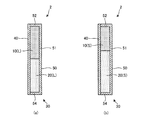
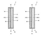
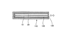
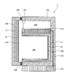
- FIGS. 1A and 1B show a schematic cross-sectional configuration of a heat storage member 1 according to the present embodiment.
- FIG. 1A and FIGS. 6A to 9A described later show a state in which the two kinds of latent heat storage materials 10 and 20 are both in the liquid phase (L)
- FIG. (B) of FIGS. 6 to 9 to be described later shows a state in which the two kinds of latent heat storage materials 10 and 20 are both solid phases (S).
- S solid phases
- the heat storage member 1 of the present embodiment includes both a first latent heat storage material 10, a second latent heat storage material 20, and latent heat storage materials 10 and 20. And a container body 30 for housing the container.
- the heat storage member 1 of this example has a plate shape (for example, a rectangular flat plate shape) as a whole.
- the latent heat storage materials 10 and 20 are stacked in the thickness direction of the heat storage member 1.
- the heat storage member 1 of this example is provided, for example, on the inner wall surface in the refrigerator.
- the heat storage member 1 is usually used in a predetermined operating temperature range and operating pressure range.
- the heat storage member 1 stores the cold by being cooled in the refrigerator, and when the operation of the refrigerator is stopped during a power failure or the like, the heat storage member 1 releases the cold and keeps the refrigerator in the refrigerator for a predetermined time.
- the operating temperature range of the heat storage member 1 includes the temperature range from the set temperature (internal temperature) of the refrigerator during operation to the ambient temperature (for example, room temperature) of the refrigerator installation location.
- the operating pressure of the heat storage member 1 is, for example, atmospheric pressure.
- Each of the latent heat storage materials 10 and 20 in the heat storage member 1 has a phase change temperature at which the phase change between the solid phase and the liquid phase (first type phase transition) occurs reversibly within the operating temperature range of the heat storage member 1. is doing.
- the latent heat storage materials 10 and 20 are in a liquid phase (L) as shown in FIG. 1A at a temperature higher than the phase change temperature (for example, room temperature), and lower than the phase change temperature (for example, during operation).
- the solid phase (S) is obtained as shown in FIG.
- the phase change temperature of the latent heat storage materials 10, 20 can be measured using a differential scanning calorimeter (DSC), a thermocouple, or the like.
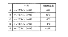
- FIG. 2 illustrates a material used as the latent heat storage material 10 that shrinks in volume when the phase changes from a liquid phase to a solid phase in the present embodiment.
- the latent heat storage material 10 of the present embodiment contains paraffin.
- Paraffin is a generic name for saturated chain hydrocarbons represented by the general formula C n H 2n + 2 .
- n-paraffin can be used not only alone but also as a mixture of two or more.
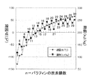
- FIG. 3 is a graph showing an example of the relationship between the number of carbon chains of n-paraffin, the freezing point (melting point), and the latent heat of fusion.
- the horizontal axis of the graph represents the number of carbon chains of n-paraffin (5 to 30), and the vertical axis represents the freezing point (° C.) or the latent heat of fusion (kJ / kg).
- the freezing point of n-paraffin increases as the number of carbon chains increases.
- the latent heat of fusion of n-paraffin is smaller when the number of carbon chains is odd than when it is even, but increases as the number of carbon chains increases as a whole.
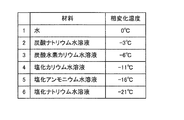
- FIG. 4 illustrates a material used as the latent heat storage material 20 that undergoes volume expansion when the phase changes from a liquid phase to a solid phase in the present embodiment.
- material 1 is water and the phase change temperature is about 0 ° C.
- Material 2 is an aqueous sodium carbonate solution with a phase change temperature of about -3 ° C.
- Material 3 is an aqueous potassium bicarbonate solution, and the phase change temperature is about ⁇ 6 ° C.
- Material 4 is an aqueous potassium chloride solution with a phase change temperature of about -11 ° C.
- Material 5 is an aqueous ammonium chloride solution with a phase change temperature of about ⁇ 16 ° C.
- Material 6 is an aqueous sodium chloride solution with a phase change temperature of about -21 ° C.
- the phase change temperature shown in FIG. 4 is a value in a saturated solution.
- Materials 2-6 can control the phase change temperature by adjusting the concentration of the solute. This will be described by taking the sodium chloride aqueous solution of material 6 as an example.
- FIG. 5 is a part of a phase diagram of an aqueous sodium chloride solution. The horizontal axis represents salt (sodium chloride) concentration (wt% NaCl), and the vertical axis represents temperature (° C.). As shown by the thick solid line in the figure, the phase change temperature of the aqueous sodium chloride solution is 0 ° C. when the salt concentration is 0 wt%, and is about ⁇ 21.3 ° C.
- the phase change temperature of the aqueous sodium chloride solution can be controlled between 0 ° C. and about ⁇ 21.3 ° C. by adjusting the salt concentration between 0 wt% and about 23.3 wt%.
- the latent heat storage materials 10 and 20 in this example contain a gelling agent.
- a gel refers to a gel that has a three-dimensional network structure formed by cross-linking molecules, and has absorbed and swelled a solvent therein. A gel is chemically stable without melting unless it breaks the structure.
- a gelling agent produces the effect of gelatinization only by making the latent heat storage materials 10 and 20 contain several weight%.
- the gel-like latent heat storage materials 10 and 20 are easy to handle because they can maintain a solid state as a whole before and after the phase change.
- Preferred latent heat storage materials 10 and 20 include a material A and a material 1 having a phase difference temperature difference of 6 ° C., a material D and a material 1 having a temperature difference of 5 ° C., and a temperature difference of 1 ° C. There are a material D and a material 3, a material C and a material 4 having the same temperature difference of 2 ° C., a material E and a material 6 having the same temperature difference of 4 ° C. As the latent heat storage materials 10 and 20, it is more preferable to use materials having the same phase change temperature.
- the material A (n-tetradecane) is used as the latent heat storage material 10
- the material 1 water is used as the latent heat storage material 20.
- Both the melting point of n-tetradecane (about 6 ° C.) and the melting point of water (about 0 ° C.) are included in the operating temperature range of the heat storage member 1.
- the volume change rate before and after the phase change is about 0.8 (volume contraction rate is about 20%). Further, when water undergoes a phase change from a liquid phase to a solid phase, the volume change rate before and after the phase change is about 1.1 (volume expansion rate is about 10%). Therefore, if the volume ratio of the latent heat storage material 10 (L) and the latent heat storage material 20 (L) in the liquid phase state is adjusted to about 1: 2, the volume shrinkage before and after the phase change of the latent heat storage material 10 The volume expansion amount before and after the phase change of the latent heat storage material 20 can be made equal.
- the sum of the volumes of S) can be made equal.
- the difference between the volumetric shrinkage before and after the phase change of the latent heat storage material 10 and the volume expansion amount before and after the phase change of the latent heat storage material 20 is the volume before the phase change (liquid phase state) of the latent heat storage material 10 and the latent heat storage. It is preferably within ⁇ 5% of the sum of the volume of the material 20 before the phase change (liquid phase state).
- the volume of the latent heat storage material 10 before the phase change is A
- the volume shrinkage before and after the phase change of the latent heat storage material 10 is x (x> 0)
- the volume of the latent heat storage material 20 before the phase change is B
- the volume expansion coefficient before and after the phase change of the latent heat storage material 20 is y (y> 0).
- the volume shrinkage before and after the phase change of the latent heat storage material 10 is A ⁇ x
- the volume expansion amount before and after the phase change of the latent heat storage material 20 is B ⁇ y.
- the difference (A ⁇ x ⁇ B ⁇ y) between the volume shrinkage A ⁇ x of the latent heat storage material 10 and the volume expansion amount B ⁇ y of the latent heat storage material 20 is (A + B) ⁇ ( ⁇ 0.05) ⁇ A ⁇ x ⁇ B ⁇ y ⁇ (A + B) ⁇ 0.05 It is preferable to satisfy the relationship. Thereby, the volume of the latent heat storage materials 10 (L) and 20 (L) when both are in the liquid phase state and the latent heat storage materials 10 (S) and 20 (S) when both are in the solid phase state. The difference from the volume can be reduced.
- volume change rate volume shrinkage
- volume shrinkage volume shrinkage
- volume expansion volume expansion
- a latent heat storage material stores, as heat energy, latent heat exchanged with the outside during a phase change of a substance.
- the heat of fusion at the melting point of the latent heat storage material is used.
- heat is continuously taken away from the outside at a constant phase change temperature, so that it is possible to suppress the temperature from rising above the melting point in a relatively long time.
- the container body 30 that houses the latent heat storage materials 10 and 20 is a hollow box having a rectangular parallelepiped outer shape.
- a rectangular flat plate-shaped first member 40 and a second member 50 formed in a shallow container shape as a separate body from the first member 40 are formed so that a space is formed inside. It has the structure combined with.
- the first member 40 and the second member 50 are made of, for example, a resin material such as polycarbonate.
- the second member 50 has the same shape (rectangular flat plate shape) as the first member 40, and four side surfaces provided on each side of the bottom surface portion 51 and perpendicular to the bottom surface portion 51 (FIG. a) and (b) show only two side portions 52 and 54.
- side portions 52 and 54 four side portions including the side portions 52 and 54 may be referred to as “side portions 52 and 54, etc.”). is doing.
- the bottom surface portion 51 and the side surface portions 52 and 54 form a predetermined accommodation space surrounded by five directions.
- the first member 40 and the second member 50 are joined to each other by, for example, an adhesive so that the first member 40 and the bottom surface portion 51 are arranged to face each other and the accommodation space of the second member 50 is hermetically sealed. . Thereby, an airtight space in which the latent heat storage materials 10 and 20 are accommodated is formed inside the first member 40 and the second member 50.
- the first member 40 and the second member 50 have a predetermined rigidity.
- the latent heat storage materials 10 (L) and 20 (L) in a liquid phase at room temperature are filled in an airtight space inside the container body 30 with almost no gap.
- the latent heat storage material 20 (L) is filled in layers so as to contact the entire inner surface of the bottom surface portion 51, and the latent heat storage material 10 (L) is formed on the inner surface of the first member 40. It is filled in layers so as to contact the whole.
- the heat storage member 1 When the heat storage member 1 is cooled in the refrigerator and the temperature is lowered, it first reaches the freezing point (about 6 ° C.) of the latent heat storage material 10 (n-tetradecane). When the freezing point of the latent heat storage material 10 is reached, the latent heat storage material 10 changes phase from a liquid phase to a solid phase and contracts at a volume contraction rate of about 20%. At this time, the volume of the latent heat storage material 10 changes, but the volume of the latent heat storage material 20 does not change. That is, the volume change of the latent heat storage materials 10 and 20 as a whole is smaller than that of a heat storage member using only the latent heat storage material 10. Therefore, deformation and mechanical breakage of the container body 30 can be suppressed.
- the latent heat storage material 10 n-tetradecane
- the temperature of the heat storage member 1 further decreases after the latent heat storage material 10 is solidified, it reaches the freezing point (about 0 ° C.) of the latent heat storage material 20 (water).
- the freezing point of the latent heat storage material 20 is reached, as shown in FIG. 1B, the latent heat storage material 20 undergoes a phase change from the liquid phase to the solid phase and expands at a volume expansion rate of about 10%. Due to the volume expansion of the latent heat storage material 20, the entire volume of the latent heat storage material 10 (S), 20 (S) changes in a direction approaching the entire volume of the latent heat storage material 10 (L), 20 (L) at room temperature. Therefore, deformation and mechanical breakage of the container body 30 can be suppressed.
- the melting point (about 0 ° C.) of the latent heat storage material 20 is reached. Changes from a solid phase to a liquid phase. At this time, the inside of the refrigerator is kept for a predetermined time by the latent heat of the latent heat storage material 20. When the temperature of the heat storage member 1 further rises, the melting point (about 6 ° C.) of the latent heat storage material 10 is reached, and the latent heat storage material 10 changes from a solid phase to a liquid phase. At this time, the inside of the refrigerator is kept cool for a predetermined time by the latent heat of the latent heat storage material 10. When the latent heat storage material 10 changes to the liquid phase, the heat storage member 1 returns to the state shown in FIG.
- a rectangular flat plate-like first member 40 and a shallow container-like second member 50 are formed by injection molding using polycarbonate.
- a gel-like latent heat storage material 10 is formed by containing n-tetradecane with several wt% gelling agent, and the gel-like latent heat storage material 20 is prepared by adding several wt% gelling agent to water.
- the gelling agent those suitable for gelation of n-tetradecane and water are used.
- the latent heat storage material 20 and the latent heat storage material 10 are filled without any gaps in this order in the accommodation space surrounded by the bottom surface 51 and the side surfaces 52 and 54 of the second member 50. And the outer frames of the frame-shaped end surfaces such as the side surface portions 52 and 54 of the second member 50 and the inner surface of the first member 40 so that the accommodation space filled with the latent heat storage materials 10 and 20 is hermetically sealed.
- the parts are joined using an adhesive.
- the heat storage member 1 of the present embodiment includes the first latent heat storage material 10 whose volume shrinks due to the phase change from the liquid phase to the solid phase when the temperature is lowered, and the liquid phase when the temperature is lowered. It has the 2nd latent heat storage material 20 whose volume expands by the phase change to a solid phase, and container 30 which stores both the 1st latent heat storage material 10 and the 2nd latent heat storage material 20 To do.
- the latent heat storage materials 10 and 20 as a whole between the time when the latent heat storage materials 10 and 20 are in the liquid phase state and the time when both of the latent heat storage materials 10 and 20 are in the solid phase state. Therefore, deformation and mechanical breakage of the container body 30 can be suppressed. Moreover, since the latent heat storage materials 10 and 20 can be filled in the container body 30 with almost no gap, the volume occupied by the latent heat storage materials 10 and 20 with respect to the volume of the container body 30 can be increased. Therefore, the heat storage effect per unit volume of the heat storage member 1 can be enhanced. That is, according to the present embodiment, it is possible to realize the heat storage member 1 having a high heat storage effect while suppressing deformation and mechanical damage of the container body 30 due to the volume change of the latent heat storage material.
- the heat storage member 1 of the present embodiment has a difference between the volume shrinkage before and after the phase change of the first latent heat storage material 10 and the volume expansion amount before and after the phase change of the second latent heat storage material 20.
- the volume of the latent heat storage material 10 before the phase change (liquid phase state) and the total volume of the second latent heat storage material 20 before the phase change (liquid phase state) is within ⁇ 5%. To do.
- the heat storage member 1 of the present embodiment is characterized in that the difference between the phase change temperature of the first latent heat storage material 10 and the phase change temperature of the second latent heat storage material 20 is within 7 ° C.
- the latent heat storage materials 10 and 20 are both in a liquid phase state, or both are in a solid phase state (the volume of the latent heat storage materials 10 and 20 as a whole is kept substantially constant. Since the temperature range can be widened, deformation and mechanical breakage of the container body 30 can be further suppressed.
- the heat storage member 1 of the present embodiment is characterized in that the first latent heat storage material 10 includes paraffin and the second latent heat storage material 20 includes water or an aqueous salt solution. According to this configuration, since the latent heat storage material 10 can be oily and the latent heat storage material 20 can be aqueous, even if one or both of the latent heat storage materials 10 and 20 are not gelled, The state where the latent heat storage material 10 and the latent heat storage material 20 are separated can be maintained.
- the heat storage member 1 of the present embodiment is characterized in that at least one of the first latent heat storage material 10 and the second latent heat storage material 20 contains a gelling agent. According to this configuration, since the shape of at least one of the latent heat storage materials 10 and 20 can be maintained without depending on the relationship between the arrangement posture of the heat storage member 1 and the vertical direction, the latent heat storage material 10 and the latent heat storage material 20 are maintained. Can be maintained in a separated state.
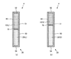
- FIG. 6A and 6B show a schematic cross-sectional configuration of the heat storage member 2 according to the present embodiment.
- symbol is attached
- the thermal storage member 2 of this Embodiment differs from the thermal storage member 1 of 1st Embodiment in each filling shape of the latent heat storage materials 10 and 20.
- the latent heat storage materials 10 and 20 are stacked in the thickness direction of the heat storage member 1, whereas the latent heat storage materials 10 and 20 of the present embodiment are the height of the heat storage member 2. It is laminated in the direction or the width direction.
- the latent heat storage material 10 is filled in the upper portion in the arrangement posture when the heat storage member 2 is used, and the latent heat storage material 20 is filled in the lower portion. That is, in this example, the latent heat storage materials 10 and 20 are laminated in the height direction of the heat storage member 2.
- the latent heat storage materials 10 (L) and 20 (L) in a liquid phase at room temperature are filled in the airtight space inside the container body 30 with almost no gap.
- the heat storage member 2 is cooled in the refrigerator and the temperature decreases, first, it reaches the freezing point (about 6 ° C.) of the latent heat storage material 10 (n-tetradecane).
- the freezing point of the latent heat storage material 10 is reached, the latent heat storage material 10 filled in the upper portion of the container body 30 changes from a liquid phase to a solid phase and contracts at a volume contraction rate of about 20%.
- the volume of the latent heat storage material 10 changes, but the volume of the latent heat storage material 20 does not change. That is, the volume change of the latent heat storage materials 10 and 20 as a whole is smaller than that of a heat storage member using only the latent heat storage material 10. Therefore, deformation and mechanical breakage of the container body 30 can be suppressed.
- the temperature of the heat storage member 2 further decreases after the latent heat storage material 10 is solidified, it reaches the freezing point (about 0 ° C.) of the latent heat storage material 20 (water).
- the freezing point of the latent heat storage material 20 is reached, as shown in FIG. 6B, the latent heat storage material 20 filled in the lower portion of the container body 30 undergoes a phase change from the liquid phase to the solid phase and has a volume of about 10%. It expands at an expansion rate. Due to the volume expansion of the latent heat storage material 20, the entire volume of the latent heat storage material 10 (S), 20 (S) changes in a direction approaching the entire volume of the latent heat storage material 10 (L), 20 (L) at room temperature. Therefore, deformation and mechanical breakage of the container body 30 can be suppressed.
- n-paraffin filled in the upper part of the container body 30 generally has a specific gravity smaller than 1, and therefore has a lower density than water, sodium chloride aqueous solution, or the like filled in the lower part of the container body 30. Furthermore, since n-paraffin is oily and water and aqueous sodium chloride solution are aqueous, they do not mix with each other. Therefore, according to the present embodiment, even if one or both of the latent heat storage materials 10 and 20 are not gelled, the latent heat storage material 10 and the latent heat storage material 20 are maintained in a separated state. can do.
- FIGS. 7A and 7B show a schematic cross-sectional configuration of the heat storage member 3 according to the present embodiment.
- symbol is attached
- the heat storage member 3 of this Embodiment is compared with the heat storage member 1 of 1st Embodiment, and the latent heat storage material 10 and the latent heat storage material 20 are the same.
- a partition plate 60 made of polycarbonate, for example is provided at the boundary.
- the partition plate 60 has a rectangular flat plate shape similar to the first member 40 and the bottom surface portion 51, for example, and is enclosed in the container body 30 together with the latent heat storage materials 10 and 20.
- the partition plate 60 can separate the filling space of the latent heat storage material 10 and the filling space of the latent heat storage material 20 in the container body 30 in a liquid-tight manner, for example.
- the partition plate 60 is movable in the thickness direction of the heat storage member 3 (in the stacking direction of the latent heat storage materials 10 and 20) along with the volume change due to the phase change of each of the latent heat storage materials 10 and 20.
- one or both of the latent heat storage materials 10 and 20 may be configured not to be gelled.
- a non-gel latent heat storage material has fluidity in a liquid phase.
- the state in which the latent heat storage material 10 and the latent heat storage material 20 are separated into layers by the partition plate 60 is maintained even when one or both of the latent heat storage materials 10 and 20 have fluidity. .
- the heat storage member 3 of the present embodiment further includes the partition plate 60 provided at the boundary between the first latent heat storage material 10 and the second latent heat storage material 20 in the container body 30. It is characterized by. According to this configuration, the state in which the latent heat storage material 10 and the latent heat storage material 20 are separated in the container body 30 can be maintained by the partition plate 60.
- the partition plate 60 is movable in accordance with the volume change of the latent heat storage materials 10 and 20. Thereby, the state in which the latent heat storage material 10 and the latent heat storage material 20 are separated can be maintained both before and after the phase change of the latent heat storage materials 10 and 20.
- the partition plate 60 liquid-tightly separates the filling space of the latent heat storage material 10 and the filling space of the latent heat storage material 20 in the container body 30. Thereby, even if at least one of the latent heat storage materials 10 and 20 is not a gel, the state where the latent heat storage material 10 and the latent heat storage material 20 are separated can be maintained.
- FIG. 8A and 8B show a schematic cross-sectional configuration of the heat storage member 4 according to the present embodiment.
- symbol is attached
- the heat storage member 4 of the present embodiment has a latent heat storage material 10 and a latent heat storage material 20 that are compared with the heat storage member 2 of the second embodiment. It is characterized in that a partition plate 70 made of, for example, polycarbonate is provided at the boundary.
- the partition plate 70 has, for example, a rectangular flat plate shape similar to the side surface portion 52 or 54 of the second member 50, and is enclosed in the container body 30 together with the latent heat storage materials 10 and 20.
- the partition plate 70 can separate the filling space of the latent heat storage material 10 and the filling space of the latent heat storage material 20 in the container body 30 in a liquid-tight manner, for example. Further, the partition plate 70 is movable in the height direction of the heat storage member 4 (in the stacking direction of the latent heat storage materials 10 and 20) in accordance with the volume change due to the phase change of each of the latent heat storage materials 10 and 20.
- one or both of the latent heat storage materials 10 and 20 may be configured not to be gelled. In the present embodiment, the state where the latent heat storage material 10 and the latent heat storage material 20 are separated by the partition plate 70 is maintained even when one or both of the latent heat storage materials 10 and 20 have fluidity.
- FIG. 9A and 9B show a schematic cross-sectional configuration of the heat storage member 5 according to the present embodiment.
- symbol is attached
- the heat storage member 5 of this Embodiment is the 1st latent heat with which the recessed part 11 was formed in the 1st member 40 side surface as a latent heat storage material with which the container body 30 was filled. It has a heat storage material 10 (L) and a second latent heat storage material 20 (L) accommodated in the recess 11.
- a plurality of concave portions 11 are formed on the surface of the latent heat storage material 10 (L) on the first member 40 side, and are arranged in a matrix when viewed from the normal direction of the surface.
- the latent heat storage material 20 (L) having substantially the same volume as the recess 11 is embedded with almost no gap.
- the latent heat storage materials 10 (L) and 20 (L) are filled in the container body 30 with almost no gap.
- the inner wall surface of the container body 30 is formed of a material having relatively high adhesion to the latent heat storage material 10.
- the heat storage member 5 is used, for example, in the arrangement posture shown in FIG. In this case, the concave 11 formation surface of the latent heat storage material 10 (L) is a horizontal upper surface. Therefore, the latent heat storage material 20 (L) is stably held in the recess 11 even if it has fluidity instead of gel.
- the heat storage member 5 When the heat storage member 5 is cooled in the refrigerator and the temperature is lowered, it first reaches the freezing point (about 6 ° C.) of the latent heat storage material 10 (n-tetradecane). When the freezing point of the latent heat storage material 10 is reached, the latent heat storage material 10 filled in the upper portion of the container body 30 changes from a liquid phase to a solid phase and contracts at a volume contraction rate of about 20%. Since the latent heat storage material 10 is highly adherent to the inner wall surface of the container body 30, the volume of the recess 11 that is not attached to the inner wall surface of the container body 30 easily expands due to the volume shrinkage, and the volume of the recess 11 is the latent heat storage material. It tends to be larger than the volume of 20 (L).
- the liquid level of the latent heat storage material 20 (L) is lower than the surface of the latent heat storage material 10 where the recess 11 is formed.
- the volume of the latent heat storage material 10 changes, but the volume of the latent heat storage material 20 does not change. That is, the volume change of the latent heat storage materials 10 and 20 as a whole is smaller than that of a heat storage member using only the latent heat storage material 10. Therefore, deformation and mechanical breakage of the container body 30 can be suppressed.
- the temperature of the heat storage member 5 further decreases after the latent heat storage material 10 is solidified, it reaches the freezing point (about 0 ° C.) of the latent heat storage material 20 (water).
- the freezing point of the latent heat storage material 20 is reached, as shown in FIG. 9B, the latent heat storage material 20 changes from a liquid phase to a solid phase and expands at a volume expansion rate of about 10%.
- the volume of the latent heat storage material 20 (S) changes in the direction approaching the volume of the recessed part 11.
- the entire volume of the latent heat storage material 10 (S), 20 (S) changes in a direction approaching the entire volume of the latent heat storage material 10 (L), 20 (L) at room temperature. Therefore, deformation and mechanical breakage of the container body 30 can be suppressed.
- the inside of the refrigerator is kept cool for a predetermined time by the latent heat of the latent heat storage material 10.
- the heat storage member 5 returns to the state shown in FIG. According to the present embodiment, the heat storage effect can be enhanced while suppressing deformation and mechanical damage of the heat storage member, as in the first embodiment.
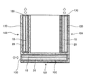
- FIG. 10 shows a schematic configuration of the heat storage container 6 according to the present embodiment.
- FIG. 11 shows a schematic cross-sectional configuration of the heat storage container 6 according to the present embodiment cut along a vertical plane.
- FIG. 12 shows a schematic cross-sectional configuration of the door member 110 of the heat storage container 6 according to the present embodiment.
- symbol is attached
- the heat storage container 6 is used as a cooler box for keeping the stored items cool. As shown in FIG. 10, the heat storage container 6 of the present embodiment is attached to a rectangular parallelepiped box 100 whose upper surface is opened and rotatably attached to one side of the opening end of the box 100 via a hinge mechanism.
- the door member 110 is capable of opening and closing the opening of the box body 100.
- a cassette-type heat storage member 130 is detachably attached to the bottom surface portion 101 and the four side surface portions 102 to 105 of the box 100 (only the side surface portions 102 and 104 are shown in FIG. 11). Insertion holes 120 to be inserted are respectively formed. 12, the door member 110 is similarly formed with an insertion hole 120 into which the cassette-type heat storage member 130 is detachably inserted.
- the thick arrows in FIGS. 11 and 12 indicate the attachment / detachment direction of the heat storage member 130.
- the heat storage member 130 has substantially the same configuration as the heat storage member 1 of the first embodiment.
- the heat storage member 130 is attached so that the latent heat storage material 10 is on the inner side (container side) of the latent heat storage materials 10 and 20.
- the heat storage member 130 is attached to all six surfaces surrounding the storage space in which the stored items are stored, but the heat storage member 130 is not necessarily attached to all six surfaces. Since the cold air flows downward, it is preferable to attach the heat storage member 130 to at least the door member 110 serving as the ceiling surface of the accommodation space.
- the cassette-type heat storage member 130 is cooled in advance by a refrigerator or the like and attached to the heat storage container 6 at the time of use. According to the present embodiment, as in the first embodiment, the heat storage effect can be enhanced while suppressing deformation and mechanical damage of the cassette-type heat storage member 130.
- FIG. 13 shows a modification of the heat storage container of the present embodiment.
- the door member 110 may be a sliding door that slides parallel to the open end of the box body 100.
- the heat storage member 130 is detachably attached to the heat storage container 6. However, if the heat storage container 6 itself can be cooled by a refrigerator or the like, the heat storage member 130 is always attached to the heat storage container 6. It may be attached. Further, the heat storage container 6 may include a cooling mechanism that cools the inside of the accommodation space, and a power source that drives the cooling mechanism.
- FIG. 14 shows a schematic cross-sectional configuration of a direct-cooling refrigerator as the heat storage container 7 according to the present embodiment.
- the heat storage container 7 has a heat storage container body 201 having a rectangular parallelepiped shape that is vertically high in the installed state. In the front of the heat storage container main body 201, rectangular openings are provided in the upper and lower stages, respectively.
- a hollow box-shaped refrigeration chamber 204 is provided in the heat storage container main body 201 with the lower rectangular opening as an opening end.
- a hollow box-shaped freezer compartment 205 is provided in the heat storage container main body 201 with the upper rectangular opening as an opening end.
- the freezer compartment door 203 is shown in a closed state.
- the freezer compartment door 203 has a rectangular flat plate shape having a region that closes the rectangular opening of the freezer compartment 205 in a closed state.
- a door member 202 is attached to the open ends of the refrigerator compartment 204 and the freezer compartment 205 through a hinge mechanism (not shown) so as to be opened and closed.
- the door member 202 has a rectangular flat plate shape having a region that closes the rectangular openings of both the refrigerator compartment 204 and the freezer compartment 205 in a closed state.
- a door packing 208 for ensuring the sealing of the refrigerator compartment 204 and the freezer compartment 205 when the door is closed is provided on the side of the door member 202 facing the outer periphery including both the refrigerator compartment 204 and the freezer compartment 205.
- Each of the heat storage container main body 201 and the door member 202 has a layer configuration in which a heat insulating material is filled between the outer wall and the inner wall.
- the heat storage container 7 has a vapor compression refrigeration cycle as a cooling mechanism for cooling the refrigerator compartment 204 and the freezer compartment 205.
- the refrigeration cycle includes a compressor 230 that compresses refrigerant, a condenser (not shown) that condenses the compressed refrigerant and dissipates heat to the outside, and an expansion unit (for example, a capillary tube) (not shown) that expands the condensed refrigerant. , An evaporator (cooler) 210 that evaporates the expanded refrigerant and cools the interior with the heat of vaporization, and a pipe 220 that connects them.
- the compressor 230 is disposed on the bottom surface of the heat storage container main body 201.
- the evaporator 210 is provided between the refrigerator compartment 204 and the freezer compartment 205 inside the heat storage container main body 201.
- the lower surface of the evaporator 210 is in contact with the latent heat storage material 10 described later, and the upper surface of the evaporator 210 is exposed in the freezer compartment 205.
- the cooling mechanism an absorption cooling device or an electronic cooling device using the Peltier effect can be used.
- a heat storage member similar to the heat storage member 1 of the first embodiment is provided inside the inner wall surface of the refrigerator compartment 204 and inside the inner wall surface of the door member 202.
- a plate-like base material 240 that forms a layered space between the inner wall surface and the inner wall surface of the refrigerator compartment 204 is provided.
- the laminar space is filled with the first latent heat storage material 10 and the second latent heat storage material 20 which are stacked on each other.
- a plate-like base material 250 that forms a layered space with the inner wall surface is provided.
- the laminar space is filled with the first latent heat storage material 10 and the second latent heat storage material 20 which are stacked on each other.
- the latent heat storage materials 10 and 20 are filled so that the latent heat storage material 20 is on the inner side (the refrigerator compartment 204 side).
- the heat storage effect can be enhanced while suppressing deformation and mechanical damage of the heat storage member, as in the first to sixth embodiments.
- the present invention is not limited to the above embodiment, and various modifications can be made.
- the heat storage member which stores cold energy was mentioned as an example, this invention is applicable not only to this but the heat storage member which stores warm heat.
- the cooler box that cools the contents is described as an example, but the present invention can also be applied to a heater box that keeps the contents warm.
- the refrigerator was mentioned as an example in the said 7th Embodiment, it is applicable also to a warm storage.
- chamber of a refrigerator or a cooler box was mentioned as an example, this invention is not restricted to this, Such as a wall material of a building, a flooring, a ceiling material, etc. It can also be used for building materials, wall materials, floor materials, etc. of automobile casings.
- the arrangement of the latent heat storage material 10 and the latent heat storage material 20 may be reversed.
- the operating temperature range of a freezer (including up to the JIS One Star standard) is ⁇ 20 ° C. to ⁇ 5 ° C. For this reason, if the combination of the latent heat storage materials 10 and 20 having a phase change temperature within the same temperature range is used, a heat storage member suitable for keeping cold in the freezer can be obtained.
- the operating temperature range of the refrigerator (refrigerated room or vegetable room) is 0 ° C to 10 ° C.
- the heat storage member suitable for the cold storage in the refrigerator compartment can be obtained.
- the operating temperature range of the heat transfer liquid for air conditioning is 7 ° C to 12 ° C.
- a heat storage member suitable for cooling the air-conveying heat transfer liquid can be obtained. Efficiency of conveyance can be realized.
- the operating temperature range of the shipping container is 15 ° C to 18 ° C.
- the combination of the latent heat storage materials 10 and 20 having a phase change temperature within the same temperature range is used, a heat storage member suitable for keeping the transport container cool or warm can be obtained, and appropriate temperature transport of pharmaceuticals and the like is realized. be able to.
- the operating temperature range of the flooring and wall material that reduces the change in room temperature is 20 ° C to 30 ° C.
- a heat storage member suitable for flooring and wall materials can be obtained, realizing energy saving and indoor comfort. can do.
- the working temperature range of flooring and wall materials that store heat during the day and dissipate heat at night is 30 ° C to 40 ° C.
- the heat storage member suitable for a flooring or a wall material can be obtained, and energy saving can be implement
- the operating temperature range of the bathtub heat storage and heat insulating material is 40 ° C to 42 ° C. For this reason, if the combination of the latent heat storage materials 10 and 20 having the phase change temperature within the same temperature range is used, a heat storage member suitable for the bathtub heat storage material can be obtained, and energy saving and long-time heat storage can be realized. Can do.
- phase change materials 10 and 20 are given as examples of the phase change material, but the present invention is not limited to this.
- Phase change materials include various materials that cause a phase transition at a certain transition point.
- the present invention is widely applicable to a heat storage member and a heat storage container using a phase change material.
- Heat storage member 6 7 Heat storage container 10, 10 (L), 10 (S) First latent heat storage material 11 Recess 20, 20 (L), 20 (S) Second latent heat storage material 30 Container Body 40 First member 50 Second member 51 Bottom surface portion 52, 54 Side surface portion 60, 70 Partition plate 100 Box body 101 Bottom surface portion 102-105 Side surface portion 110, 202 Door member 120 Insertion hole 201 Thermal storage container body 203 Freezer compartment door 204 Refrigeration room 205 Freezing room 208 Door packing 210 Evaporator 220 Piping 230 Compressor 240, 250 Base material
Abstract
The purpose of the present invention is to provide a heat storage member and heat storage container having a high heat-storage effect while suppressing deformation and mechanical damage of the container due to changes in the volume of a phase-change material. The heat storage member (1) has a first latent heat storage material (10) that shrinks in volume due to phase change when the temperature drops, a second latent heat storage material (20) that expands in volume due to phase change when the temperature drops, and a container (30) that houses both the first latent heat storage material (10) and the second latent heat storage material (20).
Description
本発明は、相変化材料を用いた蓄熱部材および蓄熱容器に関する。
The present invention relates to a heat storage member and a heat storage container using a phase change material.
従来、潜熱蓄熱材を用いた蓄熱装置が知られている。例えば特許文献1には、潜熱蓄熱材と充填ガスとが密封された密閉容器を備えた蓄熱ユニットが開示されている。密閉容器は、蓄熱材貯留部とガス貯留部とを備えている。ガス貯留部の側壁は伸縮自在の蛇腹状に形成されている。密閉容器の容積は、当該側壁の伸縮に伴って変化する。これにより、密閉容器は、潜熱蓄熱材の相変化に伴う体積変化を吸収できるようになっている。
Conventionally, a heat storage device using a latent heat storage material is known. For example, Patent Document 1 discloses a heat storage unit including a sealed container in which a latent heat storage material and a filling gas are sealed. The hermetic container includes a heat storage material storage unit and a gas storage unit. The side wall of the gas storage part is formed in a telescopic bellows shape. The volume of the sealed container changes with the expansion and contraction of the side wall. Thereby, the airtight container can absorb the volume change accompanying the phase change of a latent heat storage material.
しかしながら上記の蓄熱ユニットでは、潜熱蓄熱材が貯留される蓄熱材貯留部の他に、充填ガスが貯留されるガス貯留部と蛇腹状の側壁とを設ける必要がある。このため、密閉容器全体の容積に対して潜熱蓄熱材が占める体積が小さくなるので、蓄熱ユニットの単位体積当たりの蓄熱効果が低くなってしまうという問題があった。
However, in the above-described heat storage unit, it is necessary to provide a gas storage part in which the filling gas is stored and a bellows-like side wall in addition to the heat storage material storage part in which the latent heat storage material is stored. For this reason, since the volume which a latent heat storage material occupies with respect to the volume of the whole airtight container becomes small, there existed a problem that the thermal storage effect per unit volume of a thermal storage unit will become low.
本発明の目的は、相変化材料の体積変化による容器の変形や機械的破損を抑制しつつ、蓄熱効果の高い蓄熱部材および蓄熱容器を提供することにある。
An object of the present invention is to provide a heat storage member and a heat storage container having a high heat storage effect while suppressing deformation and mechanical breakage of the container due to volume change of the phase change material.
上記目的は、温度下降時の相変化によって体積が収縮する第1の相変化材料と、温度下降時の相変化によって体積が膨張する第2の相変化材料と、前記第1の相変化材料及び前記第2の相変化材料の双方を収容する容器体とを有することを特徴とする蓄熱部材によって達成される。
The object is to provide a first phase change material whose volume shrinks due to a phase change when the temperature drops, a second phase change material whose volume expands due to a phase change when the temperature drops, the first phase change material, and This is achieved by a heat storage member comprising a container body that contains both of the second phase change materials.
上記本発明の蓄熱部材において、前記相変化は、液相から固相への相変化であることを特徴とする。
In the heat storage member of the present invention, the phase change is a phase change from a liquid phase to a solid phase.
上記本発明の蓄熱部材において、前記第1の相変化材料の相変化前後の体積収縮量と、前記第2の相変化材料の相変化前後の体積膨張量との差が、前記第1の相変化材料の相変化前の体積と、前記第2の相変化材料の相変化前の体積との総和の±5%以内であることを特徴とする。
In the heat storage member of the present invention, the difference between the volume shrinkage before and after the phase change of the first phase change material and the volume expansion before and after the phase change of the second phase change material is the first phase. It is within ± 5% of the sum of the volume of the change material before the phase change and the volume of the second phase change material before the phase change.
上記本発明の蓄熱部材において、前記第1の相変化材料の相変化温度と、前記第2の相変化材料の相変化温度との差が7℃以内であることを特徴とする。
In the heat storage member of the present invention, the difference between the phase change temperature of the first phase change material and the phase change temperature of the second phase change material is within 7 ° C.
上記本発明の蓄熱部材において、前記第1の相変化材料は、パラフィンを含んでいることを特徴とする。
In the heat storage member of the present invention, the first phase change material includes paraffin.
上記本発明の蓄熱部材において、前記第2の相変化材料は、水、又は塩の水溶液を含んでいることを特徴とする。
In the heat storage member of the present invention, the second phase change material contains water or an aqueous salt solution.
上記本発明の蓄熱部材において、前記第1の相変化材料及び前記第2の相変化材料のうち少なくとも一方は、ゲル化剤を含んでいることを特徴とする。
In the heat storage member of the present invention, at least one of the first phase change material and the second phase change material contains a gelling agent.
上記本発明の蓄熱部材において、前記容器体内において前記第1の相変化材料と前記第2の相変化材料との境界に設けられた仕切り板をさらに有することを特徴とする。
The heat storage member of the present invention is characterized by further comprising a partition plate provided at a boundary between the first phase change material and the second phase change material in the container.
また上記目的は、上記本発明の蓄熱部材が用いられていることを特徴とする蓄熱容器によって達成される。
Also, the above object is achieved by a heat storage container using the heat storage member of the present invention.
本発明によれば、相変化材料の体積変化による容器の変形や機械的破損を抑制しつつ、蓄熱効果の高い蓄熱部材および蓄熱容器を実現できる。
According to the present invention, it is possible to realize a heat storage member and a heat storage container having a high heat storage effect while suppressing deformation and mechanical breakage of the container due to a volume change of the phase change material.
[第1の実施の形態]
本発明の第1の実施の形態による蓄熱部材について、図1~図5を用いて説明する。なお、以下の全ての図面においては、理解を容易にするため、各構成要素の寸法や比率などは適宜異ならせて図示されている。図1(a)、(b)は、本実施の形態による蓄熱部材1の概略の断面構成を示している。ここで、図1(a)及び後述する図6~図9の(a)は、2種の潜熱蓄熱材10、20がいずれも液相(L)である状態を示し、図1(b)及び後述する図6~図9の(b)は、2種の潜熱蓄熱材10、20がいずれも固相(S)である状態を示している。図1(a)、(b)に示すように、本実施の形態の蓄熱部材1は、第1の潜熱蓄熱材10と、第2の潜熱蓄熱材20と、潜熱蓄熱材10、20の双方を収容する容器体30とを有している。本例の蓄熱部材1は、全体として板状(例えば長方形平板状)の形状を有している。潜熱蓄熱材10、20は、蓄熱部材1の厚さ方向に積層されている。本例の蓄熱部材1は、例えば冷蔵庫の庫内の内壁面に設けられる。 [First Embodiment]
A heat storage member according to a first embodiment of the present invention will be described with reference to FIGS. In all of the following drawings, the dimensions and ratios of the constituent elements are appropriately varied for easy understanding. 1A and 1B show a schematic cross-sectional configuration of aheat storage member 1 according to the present embodiment. Here, FIG. 1A and FIGS. 6A to 9A described later show a state in which the two kinds of latent heat storage materials 10 and 20 are both in the liquid phase (L), and FIG. (B) of FIGS. 6 to 9 to be described later shows a state in which the two kinds of latent heat storage materials 10 and 20 are both solid phases (S). As shown in FIGS. 1A and 1B, the heat storage member 1 of the present embodiment includes both a first latent heat storage material 10, a second latent heat storage material 20, and latent heat storage materials 10 and 20. And a container body 30 for housing the container. The heat storage member 1 of this example has a plate shape (for example, a rectangular flat plate shape) as a whole. The latent heat storage materials 10 and 20 are stacked in the thickness direction of the heat storage member 1. The heat storage member 1 of this example is provided, for example, on the inner wall surface in the refrigerator.
本発明の第1の実施の形態による蓄熱部材について、図1~図5を用いて説明する。なお、以下の全ての図面においては、理解を容易にするため、各構成要素の寸法や比率などは適宜異ならせて図示されている。図1(a)、(b)は、本実施の形態による蓄熱部材1の概略の断面構成を示している。ここで、図1(a)及び後述する図6~図9の(a)は、2種の潜熱蓄熱材10、20がいずれも液相(L)である状態を示し、図1(b)及び後述する図6~図9の(b)は、2種の潜熱蓄熱材10、20がいずれも固相(S)である状態を示している。図1(a)、(b)に示すように、本実施の形態の蓄熱部材1は、第1の潜熱蓄熱材10と、第2の潜熱蓄熱材20と、潜熱蓄熱材10、20の双方を収容する容器体30とを有している。本例の蓄熱部材1は、全体として板状(例えば長方形平板状)の形状を有している。潜熱蓄熱材10、20は、蓄熱部材1の厚さ方向に積層されている。本例の蓄熱部材1は、例えば冷蔵庫の庫内の内壁面に設けられる。 [First Embodiment]
A heat storage member according to a first embodiment of the present invention will be described with reference to FIGS. In all of the following drawings, the dimensions and ratios of the constituent elements are appropriately varied for easy understanding. 1A and 1B show a schematic cross-sectional configuration of a
蓄熱部材1は、通常、所定の使用温度範囲及び使用圧力範囲で用いられる。例えば蓄熱部材1は、冷蔵庫が稼動しているときには庫内で冷却されることにより冷熱を蓄え、停電時等に冷蔵庫の稼動が停止したときには冷熱を放出して庫内を所定時間保冷する。この場合、稼働時の冷蔵庫の設定温度(庫内温度)から冷蔵庫設置場所の雰囲気温度(例えば室温)までの温度範囲が、蓄熱部材1の使用温度範囲に含まれる。また、蓄熱部材1の使用圧力は、例えば大気圧である。
The heat storage member 1 is usually used in a predetermined operating temperature range and operating pressure range. For example, when the refrigerator is operating, the heat storage member 1 stores the cold by being cooled in the refrigerator, and when the operation of the refrigerator is stopped during a power failure or the like, the heat storage member 1 releases the cold and keeps the refrigerator in the refrigerator for a predetermined time. In this case, the operating temperature range of the heat storage member 1 includes the temperature range from the set temperature (internal temperature) of the refrigerator during operation to the ambient temperature (for example, room temperature) of the refrigerator installation location. Moreover, the operating pressure of the heat storage member 1 is, for example, atmospheric pressure.
蓄熱部材1内の潜熱蓄熱材10、20はいずれも、固相及び液相間の相変化(第一種相転移)が可逆的に生じる相変化温度を蓄熱部材1の使用温度範囲内に有している。潜熱蓄熱材10、20は、相変化温度よりも高い温度(例えば、室温)では図1(a)に示すように液相(L)となり、相変化温度よりも低い温度(例えば、稼働時の冷蔵庫の庫内温度)では図1(b)に示すように固相(S)となる。潜熱蓄熱材10、20の相変化温度は、示差走査熱量計(DSC)、又は熱電対等を用いて測定することができる。液相から固相への相変化が生じると、潜熱蓄熱材10は体積が収縮し、潜熱蓄熱材20は体積が膨張する。
Each of the latent heat storage materials 10 and 20 in the heat storage member 1 has a phase change temperature at which the phase change between the solid phase and the liquid phase (first type phase transition) occurs reversibly within the operating temperature range of the heat storage member 1. is doing. The latent heat storage materials 10 and 20 are in a liquid phase (L) as shown in FIG. 1A at a temperature higher than the phase change temperature (for example, room temperature), and lower than the phase change temperature (for example, during operation). At the refrigerator temperature, the solid phase (S) is obtained as shown in FIG. The phase change temperature of the latent heat storage materials 10, 20 can be measured using a differential scanning calorimeter (DSC), a thermocouple, or the like. When the phase change from the liquid phase to the solid phase occurs, the volume of the latent heat storage material 10 contracts and the volume of the latent heat storage material 20 expands.
図2は、本実施の形態において、液相から固相に相変化したときに体積収縮する潜熱蓄熱材10として用いられる材料を例示している。図2に示すように、本実施の形態の潜熱蓄熱材10はパラフィンを含んでいる。パラフィンとは、一般式CnH2n+2で表される飽和鎖式炭化水素の総称をいう。例えば、材料Aはn-パラフィン(炭素鎖数n=14)であり、相変化温度は約6℃である。材料Bはn-パラフィン(炭素鎖数n=15)であり、相変化温度は約10℃である。材料Cはn-パラフィン(炭素鎖数n=12)であり、相変化温度は約-9℃である。材料Dはn-パラフィン(炭素鎖数n=13)であり、相変化温度は約-5℃である。材料Eはn-パラフィン(炭素鎖数n=11)であり、相変化温度は約-25℃である。なお、n-パラフィンは、単体で用いられるだけでなく、2種以上を混合して用いることもできる。
FIG. 2 illustrates a material used as the latent heat storage material 10 that shrinks in volume when the phase changes from a liquid phase to a solid phase in the present embodiment. As shown in FIG. 2, the latent heat storage material 10 of the present embodiment contains paraffin. Paraffin is a generic name for saturated chain hydrocarbons represented by the general formula C n H 2n + 2 . For example, material A is n-paraffin (carbon chain number n = 14) and the phase change temperature is about 6 ° C. Material B is n-paraffin (carbon chain number n = 15), and the phase change temperature is about 10 ° C. Material C is n-paraffin (carbon chain number n = 12), and the phase change temperature is about −9 ° C. Material D is n-paraffin (carbon chain number n = 13), and the phase change temperature is about −5 ° C. Material E is n-paraffin (carbon chain number n = 11) and the phase change temperature is about −25 ° C. In addition, n-paraffin can be used not only alone but also as a mixture of two or more.
図3は、n-パラフィンの炭素鎖数と凝固点(融点)及び融解潜熱との関係の一例を示すグラフである。グラフの横軸はn-パラフィンの炭素鎖数(5~30)を表し、縦軸は凝固点(℃)又は融解潜熱(kJ/kg)を表している。図3に示すように、n-パラフィンの凝固点は、炭素鎖数が大きくなるほど高くなる。また、n-パラフィンの融解潜熱は、炭素鎖数が奇数の場合には偶数の場合よりも小さくなるものの、全体として炭素鎖数が大きくなるほど大きくなる。
FIG. 3 is a graph showing an example of the relationship between the number of carbon chains of n-paraffin, the freezing point (melting point), and the latent heat of fusion. The horizontal axis of the graph represents the number of carbon chains of n-paraffin (5 to 30), and the vertical axis represents the freezing point (° C.) or the latent heat of fusion (kJ / kg). As shown in FIG. 3, the freezing point of n-paraffin increases as the number of carbon chains increases. Further, the latent heat of fusion of n-paraffin is smaller when the number of carbon chains is odd than when it is even, but increases as the number of carbon chains increases as a whole.
図4は、本実施の形態において、液相から固相に相変化したときに体積膨張する潜熱蓄熱材20として用いられる材料を例示している。図4に示すように、材料1は水であり、相変化温度は約0℃である。材料2は炭酸ナトリウム水溶液であり、相変化温度は約-3℃である。材料3は炭酸水素カリウム水溶液であり、相変化温度は約-6℃である。材料4は塩化カリウム水溶液であり、相変化温度は約-11℃である。材料5は塩化アンモニウム水溶液であり、相変化温度は約-16℃である。材料6は塩化ナトリウム水溶液であり、相変化温度は約-21℃である。
FIG. 4 illustrates a material used as the latent heat storage material 20 that undergoes volume expansion when the phase changes from a liquid phase to a solid phase in the present embodiment. As shown in FIG. 4, material 1 is water and the phase change temperature is about 0 ° C. Material 2 is an aqueous sodium carbonate solution with a phase change temperature of about -3 ° C. Material 3 is an aqueous potassium bicarbonate solution, and the phase change temperature is about −6 ° C. Material 4 is an aqueous potassium chloride solution with a phase change temperature of about -11 ° C. Material 5 is an aqueous ammonium chloride solution with a phase change temperature of about −16 ° C. Material 6 is an aqueous sodium chloride solution with a phase change temperature of about -21 ° C.
ここで、材料2~6において、図4に示す相変化温度は飽和溶液での値である。材料2~6は、溶質の濃度を調整することによって相変化温度を制御できる。この点について、材料6の塩化ナトリウム水溶液を例に挙げて説明する。図5は、塩化ナトリウム水溶液の状態図の一部である。横軸は塩(塩化ナトリウム)の濃度(wt%NaCl)を表し、縦軸は温度(℃)を表している。図中の太実線で示すように、塩化ナトリウム水溶液の相変化温度は、塩の濃度が0wt%のとき0℃であり、塩の濃度が約23.3wt%のとき約-21.3℃となる。濃度0wt%~23.3wt%の範囲では、塩の濃度が高くなるほど相変化温度が低くなる。したがって、塩の濃度を0wt%~約23.3wt%の間で調整することによって、塩化ナトリウム水溶液の相変化温度を0℃~約-21.3℃の間で制御することができる。
Here, in materials 2 to 6, the phase change temperature shown in FIG. 4 is a value in a saturated solution. Materials 2-6 can control the phase change temperature by adjusting the concentration of the solute. This will be described by taking the sodium chloride aqueous solution of material 6 as an example. FIG. 5 is a part of a phase diagram of an aqueous sodium chloride solution. The horizontal axis represents salt (sodium chloride) concentration (wt% NaCl), and the vertical axis represents temperature (° C.). As shown by the thick solid line in the figure, the phase change temperature of the aqueous sodium chloride solution is 0 ° C. when the salt concentration is 0 wt%, and is about −21.3 ° C. when the salt concentration is about 23.3 wt%. Become. In the concentration range of 0 wt% to 23.3 wt%, the higher the salt concentration, the lower the phase change temperature. Therefore, the phase change temperature of the aqueous sodium chloride solution can be controlled between 0 ° C. and about −21.3 ° C. by adjusting the salt concentration between 0 wt% and about 23.3 wt%.
本例の潜熱蓄熱材10、20には、ゲル化剤が含有されている。ゲルとは、分子が架橋されることで三次元的な網目構造を形成し、その内部に溶媒を吸収し膨潤したものをいう。ゲルは、構造を壊さない限り溶けず化学的に安定である。ゲル化剤は、潜熱蓄熱材10、20に数重量%含有させるだけでゲル化の効果を生じる。ゲル状の潜熱蓄熱材10、20は、相変化の前後で全体として固体状態を維持できるので取扱いが容易である。
The latent heat storage materials 10 and 20 in this example contain a gelling agent. A gel refers to a gel that has a three-dimensional network structure formed by cross-linking molecules, and has absorbed and swelled a solvent therein. A gel is chemically stable without melting unless it breaks the structure. A gelling agent produces the effect of gelatinization only by making the latent heat storage materials 10 and 20 contain several weight%. The gel-like latent heat storage materials 10 and 20 are easy to handle because they can maintain a solid state as a whole before and after the phase change.
潜熱蓄熱材10、20の組合せとしては、それぞれの相変化温度がより近いもの(例えば、それぞれの相変化温度の温度差が7℃程度以内のもの)を用いることが好ましい。好ましい潜熱蓄熱材10、20の組合せとしては、相変化温度の温度差が6℃である材料A及び材料1、同温度差が5℃である材料D及び材料1、同温度差が1℃である材料D及び材料3、同温度差が2℃である材料C及び材料4、同温度差が4℃である材料E及び材料6等がある。潜熱蓄熱材10、20としては、それぞれの相変化温度が等しいもの同士を用いることがより好ましい。
As the combination of the latent heat storage materials 10 and 20, it is preferable to use a material having a closer phase change temperature (for example, a temperature difference between the phase change temperatures within about 7 ° C.). Preferred latent heat storage materials 10 and 20 include a material A and a material 1 having a phase difference temperature difference of 6 ° C., a material D and a material 1 having a temperature difference of 5 ° C., and a temperature difference of 1 ° C. There are a material D and a material 3, a material C and a material 4 having the same temperature difference of 2 ° C., a material E and a material 6 having the same temperature difference of 4 ° C. As the latent heat storage materials 10 and 20, it is more preferable to use materials having the same phase change temperature.
本例では、潜熱蓄熱材10として材料A(n-テトラデカン)、潜熱蓄熱材20として材料1(水)を用いる。n-テトラデカンの融点(約6℃)及び水の融点(約0℃)は、いずれも蓄熱部材1の使用温度範囲内に含まれる。
In this example, the material A (n-tetradecane) is used as the latent heat storage material 10, and the material 1 (water) is used as the latent heat storage material 20. Both the melting point of n-tetradecane (about 6 ° C.) and the melting point of water (about 0 ° C.) are included in the operating temperature range of the heat storage member 1.
n-テトラデカンが液相から固相に相変化したとき、相変化前後の体積変化率は約0.8(体積収縮率約20%)である。また、水が液相から固相に相変化したとき、相変化前後の体積変化率は約1.1(体積膨張率約10%)である。したがって、液相状態にあるときの潜熱蓄熱材10(L)及び潜熱蓄熱材20(L)の体積比を1:2程度に調整すれば、潜熱蓄熱材10の相変化前後の体積収縮量と、潜熱蓄熱材20の相変化前後の体積膨張量とを等しくすることができる。すなわち、いずれも液相状態にある潜熱蓄熱材10(L)及び潜熱蓄熱材20(L)の体積の総和と、いずれも固相状態にある潜熱蓄熱材10(S)及び潜熱蓄熱材20(S)の体積の総和とを等しくすることができる。
When n-tetradecane undergoes a phase change from a liquid phase to a solid phase, the volume change rate before and after the phase change is about 0.8 (volume contraction rate is about 20%). Further, when water undergoes a phase change from a liquid phase to a solid phase, the volume change rate before and after the phase change is about 1.1 (volume expansion rate is about 10%). Therefore, if the volume ratio of the latent heat storage material 10 (L) and the latent heat storage material 20 (L) in the liquid phase state is adjusted to about 1: 2, the volume shrinkage before and after the phase change of the latent heat storage material 10 The volume expansion amount before and after the phase change of the latent heat storage material 20 can be made equal. That is, the total volume of the latent heat storage material 10 (L) and the latent heat storage material 20 (L), both in the liquid phase state, and the latent heat storage material 10 (S) and the latent heat storage material 20 (in the solid phase state, both. The sum of the volumes of S) can be made equal.
潜熱蓄熱材10の相変化前後の体積収縮量と、潜熱蓄熱材20の相変化前後の体積膨張量との差は、潜熱蓄熱材10の相変化前(液相状態)の体積と、潜熱蓄熱材20の相変化前(液相状態)の体積との総和の±5%以内であることが好ましい。
The difference between the volumetric shrinkage before and after the phase change of the latent heat storage material 10 and the volume expansion amount before and after the phase change of the latent heat storage material 20 is the volume before the phase change (liquid phase state) of the latent heat storage material 10 and the latent heat storage. It is preferably within ± 5% of the sum of the volume of the material 20 before the phase change (liquid phase state).
例えば、潜熱蓄熱材10の相変化前の体積をAとし、潜熱蓄熱材10の相変化前後の体積収縮率をx(x>0)とし、潜熱蓄熱材20の相変化前の体積をBとし、潜熱蓄熱材20の相変化前後の体積膨張率をy(y>0)とする。この場合、潜熱蓄熱材10の相変化前後の体積収縮量はA・xとなり、潜熱蓄熱材20の相変化前後の体積膨張量はB・yとなる。したがって、潜熱蓄熱材10の体積収縮量A・xと潜熱蓄熱材20の体積膨張量B・yとの差(A・x-B・y)は、
(A+B)×(-0.05)≦A・x-B・y≦(A+B)×0.05
の関係を満たすことが好ましい。これにより、いずれも液相状態にあるときの潜熱蓄熱材10(L)、20(L)の体積と、いずれも固相状態にあるときの潜熱蓄熱材10(S)、20(S)の体積との差を小さくすることができる。 For example, the volume of the latentheat storage material 10 before the phase change is A, the volume shrinkage before and after the phase change of the latent heat storage material 10 is x (x> 0), and the volume of the latent heat storage material 20 before the phase change is B. The volume expansion coefficient before and after the phase change of the latent heat storage material 20 is y (y> 0). In this case, the volume shrinkage before and after the phase change of the latent heat storage material 10 is A · x, and the volume expansion amount before and after the phase change of the latent heat storage material 20 is B · y. Therefore, the difference (A · x−B · y) between the volume shrinkage A · x of the latent heat storage material 10 and the volume expansion amount B · y of the latent heat storage material 20 is
(A + B) × (−0.05) ≦ A · x−B · y ≦ (A + B) × 0.05
It is preferable to satisfy the relationship. Thereby, the volume of the latent heat storage materials 10 (L) and 20 (L) when both are in the liquid phase state and the latent heat storage materials 10 (S) and 20 (S) when both are in the solid phase state. The difference from the volume can be reduced.
(A+B)×(-0.05)≦A・x-B・y≦(A+B)×0.05
の関係を満たすことが好ましい。これにより、いずれも液相状態にあるときの潜熱蓄熱材10(L)、20(L)の体積と、いずれも固相状態にあるときの潜熱蓄熱材10(S)、20(S)の体積との差を小さくすることができる。 For example, the volume of the latent
(A + B) × (−0.05) ≦ A · x−B · y ≦ (A + B) × 0.05
It is preferable to satisfy the relationship. Thereby, the volume of the latent heat storage materials 10 (L) and 20 (L) when both are in the liquid phase state and the latent heat storage materials 10 (S) and 20 (S) when both are in the solid phase state. The difference from the volume can be reduced.
ここで、本明細書中における「体積変化率」、「体積収縮量」、「体積収縮率」、「体積膨張量」及び「体積膨張率」の定義について説明する。これらは、液相と固相との間で相変化する材料において、液相から固相に相変化したときの同重量での体積変化の程度を表す用語である。
Here, the definitions of “volume change rate”, “volume shrinkage”, “volume shrinkage”, “volume expansion” and “volume expansion” in this specification will be described. These are terms representing the degree of volume change at the same weight when a phase change is made from a liquid phase to a solid phase in a material that changes between a liquid phase and a solid phase.
「体積変化率」は、液相(相変化前)の体積に対する固相(相変化後)の体積の比(=(固相の体積)/(液相の体積))を表す。「体積変化率」は、液相から固相への相変化で体積膨張する材料及び体積収縮する材料のいずれにも共通に用いられる。「体積変化率」は、液相から固相への相変化で体積膨張する材料の場合には1より大きく、液相から固相への相変化で体積収縮する材料の場合には1より小さい。液相及び固相の体積の計測には、例えば、化学変化を起こさない溶液中に材料を浸漬して各相の体積を計測するアルキメデス法等を用いることができる。
“Volume change rate” represents the ratio of the volume of the solid phase (after phase change) to the volume of the liquid phase (before phase change) (= (volume of solid phase) / (volume of liquid phase)). “Volume change rate” is commonly used for both a material that expands by volume and a material that shrinks by volume change from a liquid phase to a solid phase. “Volume change rate” is larger than 1 in the case of a material that expands in volume by a phase change from a liquid phase to a solid phase, and smaller than 1 in the case of a material that contracts in a volume by a phase change from a liquid phase to a solid phase . For the measurement of the volume of the liquid phase and the solid phase, for example, the Archimedes method in which the material is immersed in a solution that does not cause a chemical change and the volume of each phase is measured can be used.
「体積収縮量」及び「体積収縮率」は、同重量において(液相の体積)>(固相の体積)の関係を満たす材料、すなわち、液相から固相への相変化で体積収縮する材料(例えばパラフィン)に用いられる。
「体積収縮量」は、液相(相変化前)の体積と固相(相変化後)の体積との差(=(液相の体積)-(固相の体積))を表す。「体積収縮量」は正の値をとる。
「体積収縮率」は、液相(相変化前)の体積に対する体積収縮量の比(=(体積収縮量)/(液相の体積)=((液相の体積)-(固相の体積))/(液相の体積))を表す。「体積収縮率」は正の値をとり、例えば百分率(%)で表現される。 “Volume shrinkage” and “volume shrinkage” are materials that satisfy the relationship of (volume of liquid phase)> (volume of solid phase) at the same weight, that is, volume shrinkage due to phase change from liquid phase to solid phase. Used for materials (eg paraffin).
“Volume shrinkage” represents the difference between the volume of the liquid phase (before phase change) and the volume of the solid phase (after phase change) (= (volume of liquid phase) − (volume of solid phase)). “Volume shrinkage” takes a positive value.
“Volume shrinkage” is the ratio of volume shrinkage to volume of liquid phase (before phase change) (= (volume shrinkage) / (volume of liquid phase) = ((volume of liquid phase) − (volume of solid phase). )) / (Volume of liquid phase)). “Volume shrinkage” takes a positive value and is expressed, for example, as a percentage (%).
「体積膨張量」及び「体積膨張率」は、同重量において(固相の体積)>(液相の体積)の関係を満たす材料、すなわち、液相から固相への相変化で体積膨張する材料(例えば水)に用いられる。
「体積膨張量」は、固相(相変化後)の体積と液相(相変化前)の体積との差(=(固相の体積)-(液相の体積))を表す。「体積膨張量」は正の値をとる。
「体積膨張率」は、液相(相変化前)の体積に対する体積膨張量の比(=(体積膨張量)/(液相の体積)=((固相の体積)-(液相の体積))/(液相の体積))を表す。「体積膨張率」は正の値をとり、例えば百分率(%)で表現される。 “Volume expansion amount” and “volume expansion coefficient” are materials that satisfy the relationship (volume of solid phase)> (volume of liquid phase) at the same weight, that is, volume expansion by phase change from liquid phase to solid phase. Used for materials (eg water).
“Volume expansion” represents the difference between the volume of the solid phase (after phase change) and the volume of the liquid phase (before phase change) (= (volume of solid phase) − (volume of liquid phase)). The “volume expansion amount” takes a positive value.
“Volume expansion ratio” is a ratio of volume expansion amount to volume of liquid phase (before phase change) (= (volume expansion amount) / (volume of liquid phase) = ((volume of solid phase) − (volume of liquid phase). )) / (Volume of liquid phase)). The “volume expansion coefficient” takes a positive value and is expressed, for example, as a percentage (%).
一般に潜熱蓄熱材は、物質の相変化の際に外部とやり取りされる潜熱を熱エネルギーとして蓄える。例えば、固-液間の相変化を利用した蓄熱では、潜熱蓄熱材の融点での融解熱を利用する。相変化の際に固体と液体の二相が混在する限り一定の相変化温度で外部より熱を奪い続けるので、比較的長時間において融点以上に温度が上がるのを抑制できる。
Generally, a latent heat storage material stores, as heat energy, latent heat exchanged with the outside during a phase change of a substance. For example, in heat storage using phase change between solid and liquid, the heat of fusion at the melting point of the latent heat storage material is used. As long as two phases of solid and liquid coexist at the time of phase change, heat is continuously taken away from the outside at a constant phase change temperature, so that it is possible to suppress the temperature from rising above the melting point in a relatively long time.
潜熱蓄熱材10、20を収容する容器体30は、直方体状の外形状を有する中空の箱体である。本例の容器体30は、長方形平板状の第1部材40と、第1部材40とは別体として浅底容器状に成形された第2部材50とが、内側に空間が形成されるように組み合わされた構成を有している。第1部材40及び第2部材50は、例えば、ポリカーボネート等の樹脂材料により形成されている。第2部材50は、第1部材40と同形状(長方形平板状)の底面部51と、底面部51の各辺に設けられ、底面部51に対して垂直な4つの側面部(図1(a)、(b)では2つの側面部52、54のみを示している。以下、側面部52、54を含む4つの側面部を「側面部52、54等」という場合がある)とを有している。底面部51及び側面部52、54等は、5方向が囲まれた所定の収容空間を形成する。第1部材40及び第2部材50は、第1部材40と底面部51とが対向配置されて第2部材50の収容空間が気密に密閉されるように、例えば接着剤により互いに接合されている。これにより、第1部材40及び第2部材50の内側には、潜熱蓄熱材10、20が収容される気密空間が形成される。例えば第1部材40及び第2部材50は、所定の剛性を有している。
The container body 30 that houses the latent heat storage materials 10 and 20 is a hollow box having a rectangular parallelepiped outer shape. In the container body 30 of this example, a rectangular flat plate-shaped first member 40 and a second member 50 formed in a shallow container shape as a separate body from the first member 40 are formed so that a space is formed inside. It has the structure combined with. The first member 40 and the second member 50 are made of, for example, a resin material such as polycarbonate. The second member 50 has the same shape (rectangular flat plate shape) as the first member 40, and four side surfaces provided on each side of the bottom surface portion 51 and perpendicular to the bottom surface portion 51 (FIG. a) and (b) show only two side portions 52 and 54. Hereinafter, four side portions including the side portions 52 and 54 may be referred to as “ side portions 52 and 54, etc.”). is doing. The bottom surface portion 51 and the side surface portions 52 and 54 form a predetermined accommodation space surrounded by five directions. The first member 40 and the second member 50 are joined to each other by, for example, an adhesive so that the first member 40 and the bottom surface portion 51 are arranged to face each other and the accommodation space of the second member 50 is hermetically sealed. . Thereby, an airtight space in which the latent heat storage materials 10 and 20 are accommodated is formed inside the first member 40 and the second member 50. For example, the first member 40 and the second member 50 have a predetermined rigidity.
図1(a)に示すように、例えば室温において液相状態にある潜熱蓄熱材10(L)、20(L)は、容器体30内部の気密空間内にほぼ隙間なく充填されている。本例では、潜熱蓄熱材20(L)は、底面部51の内側表面の全体に接触するように層状に充填されており、潜熱蓄熱材10(L)は、第1部材40の内側表面の全体に接触するように層状に充填されている。
As shown in FIG. 1 (a), for example, the latent heat storage materials 10 (L) and 20 (L) in a liquid phase at room temperature are filled in an airtight space inside the container body 30 with almost no gap. In this example, the latent heat storage material 20 (L) is filled in layers so as to contact the entire inner surface of the bottom surface portion 51, and the latent heat storage material 10 (L) is formed on the inner surface of the first member 40. It is filled in layers so as to contact the whole.
蓄熱部材1が冷蔵庫内で冷却されて温度が低下すると、まず潜熱蓄熱材10(n-テトラデカン)の凝固点(約6℃)に到達する。潜熱蓄熱材10の凝固点に到達すると、潜熱蓄熱材10は、液相から固相に相変化して約20%の体積収縮率で収縮する。このとき、潜熱蓄熱材10の体積は変化するが、潜熱蓄熱材20の体積は変化しない。すなわち、潜熱蓄熱材10、20全体としての体積変化は、潜熱蓄熱材10のみを用いた蓄熱部材と比較すると小さくなる。したがって、容器体30の変形や機械的破損を抑制することができる。
When the heat storage member 1 is cooled in the refrigerator and the temperature is lowered, it first reaches the freezing point (about 6 ° C.) of the latent heat storage material 10 (n-tetradecane). When the freezing point of the latent heat storage material 10 is reached, the latent heat storage material 10 changes phase from a liquid phase to a solid phase and contracts at a volume contraction rate of about 20%. At this time, the volume of the latent heat storage material 10 changes, but the volume of the latent heat storage material 20 does not change. That is, the volume change of the latent heat storage materials 10 and 20 as a whole is smaller than that of a heat storage member using only the latent heat storage material 10. Therefore, deformation and mechanical breakage of the container body 30 can be suppressed.
潜熱蓄熱材10が凝固した後、蓄熱部材1の温度がさらに低下すると、潜熱蓄熱材20(水)の凝固点(約0℃)に到達する。潜熱蓄熱材20の凝固点に到達すると、図1(b)に示すように、潜熱蓄熱材20は、液相から固相に相変化して約10%の体積膨張率で膨張する。潜熱蓄熱材20の体積膨張により、潜熱蓄熱材10(S)、20(S)全体の体積は、室温における潜熱蓄熱材10(L)、20(L)全体の体積に近づく方向に変化する。したがって、容器体30の変形や機械的破損を抑制することができる。
When the temperature of the heat storage member 1 further decreases after the latent heat storage material 10 is solidified, it reaches the freezing point (about 0 ° C.) of the latent heat storage material 20 (water). When the freezing point of the latent heat storage material 20 is reached, as shown in FIG. 1B, the latent heat storage material 20 undergoes a phase change from the liquid phase to the solid phase and expands at a volume expansion rate of about 10%. Due to the volume expansion of the latent heat storage material 20, the entire volume of the latent heat storage material 10 (S), 20 (S) changes in a direction approaching the entire volume of the latent heat storage material 10 (L), 20 (L) at room temperature. Therefore, deformation and mechanical breakage of the container body 30 can be suppressed.
図1(b)に示す状態から、例えば停電等により冷蔵庫内の温度が上昇して蓄熱部材1の温度が上昇すると、潜熱蓄熱材20の融点(約0℃)に到達し、潜熱蓄熱材20が固相から液相に相変化する。このとき、潜熱蓄熱材20の潜熱により冷蔵庫内が所定時間保冷される。蓄熱部材1の温度がさらに上昇すると、潜熱蓄熱材10の融点(約6℃)に到達し、潜熱蓄熱材10が固相から液相に相変化する。このとき、潜熱蓄熱材10の潜熱により冷蔵庫内が所定時間保冷される。潜熱蓄熱材10が液相に相変化すると、蓄熱部材1は図1(a)に示す状態に戻る。
From the state shown in FIG. 1B, for example, when the temperature in the refrigerator rises due to a power failure or the like and the temperature of the heat storage member 1 rises, the melting point (about 0 ° C.) of the latent heat storage material 20 is reached. Changes from a solid phase to a liquid phase. At this time, the inside of the refrigerator is kept for a predetermined time by the latent heat of the latent heat storage material 20. When the temperature of the heat storage member 1 further rises, the melting point (about 6 ° C.) of the latent heat storage material 10 is reached, and the latent heat storage material 10 changes from a solid phase to a liquid phase. At this time, the inside of the refrigerator is kept cool for a predetermined time by the latent heat of the latent heat storage material 10. When the latent heat storage material 10 changes to the liquid phase, the heat storage member 1 returns to the state shown in FIG.
ここで、ゲル状の潜熱蓄熱材10、20は流動性を有しないため、液相状態や液相から固相への相変化中の状態において、潜熱蓄熱材10(L)、20(L)が下方に流れ落ちてしまうことはない。したがって、相変化が繰り返されても、潜熱蓄熱材10(L)、20(L)の形状、及び潜熱蓄熱材10(S)、20(S)の形状は、蓄熱部材1の配置姿勢と鉛直方向との関係にはさほど依存せずに維持される。
Here, since the gel-like latent heat storage materials 10 and 20 do not have fluidity, the latent heat storage materials 10 (L) and 20 (L) in a liquid phase state or a state during phase change from a liquid phase to a solid phase. Will not flow down. Therefore, even if the phase change is repeated, the shapes of the latent heat storage materials 10 (L) and 20 (L) and the shapes of the latent heat storage materials 10 (S) and 20 (S) are perpendicular to the arrangement posture of the heat storage member 1. It is maintained without much dependency on the relationship with the direction.
次に、本実施の形態による蓄熱部材1の製造方法の一例について簡単に説明する。まず、ポリカーボネートを用いて、長方形平板状の第1部材40と浅底容器状の第2部材50とをそれぞれ射出成形により形成する。また、n-テトラデカンに数重量%のゲル化剤を含有させてゲル状の潜熱蓄熱材10を形成するとともに、水に数重量%のゲル化剤を含有させてゲル状の潜熱蓄熱材20を形成する。ここで、ゲル化剤としては、n-テトラデカン及び水のそれぞれのゲル化に適したものを使用する。次に、第2部材50の底面部51及び側面部52、54等で囲まれた収容空間内に、潜熱蓄熱材20及び潜熱蓄熱材10をこの順に隙間なく充填する。そして、潜熱蓄熱材10、20が充填された収容空間が気密に密閉されるように、第2部材50の側面部52、54等の枠状の端面と第1部材40の内側表面の外枠部分とを接着剤を用いて接合する。以上の手順により、本実施の形態による蓄熱部材1が作製される。
Next, an example of a method for manufacturing the heat storage member 1 according to the present embodiment will be briefly described. First, a rectangular flat plate-like first member 40 and a shallow container-like second member 50 are formed by injection molding using polycarbonate. Further, a gel-like latent heat storage material 10 is formed by containing n-tetradecane with several wt% gelling agent, and the gel-like latent heat storage material 20 is prepared by adding several wt% gelling agent to water. Form. Here, as the gelling agent, those suitable for gelation of n-tetradecane and water are used. Next, the latent heat storage material 20 and the latent heat storage material 10 are filled without any gaps in this order in the accommodation space surrounded by the bottom surface 51 and the side surfaces 52 and 54 of the second member 50. And the outer frames of the frame-shaped end surfaces such as the side surface portions 52 and 54 of the second member 50 and the inner surface of the first member 40 so that the accommodation space filled with the latent heat storage materials 10 and 20 is hermetically sealed. The parts are joined using an adhesive. With the above procedure, the heat storage member 1 according to the present embodiment is manufactured.
以上説明したように、本実施の形態の蓄熱部材1は、温度下降時の液相から固相への相変化によって体積が収縮する第1の潜熱蓄熱材10と、温度下降時の液相から固相への相変化によって体積が膨張する第2の潜熱蓄熱材20と、第1の潜熱蓄熱材10及び第2の潜熱蓄熱材20の双方を収容する容器体30とを有することを特徴とする。
As described above, the heat storage member 1 of the present embodiment includes the first latent heat storage material 10 whose volume shrinks due to the phase change from the liquid phase to the solid phase when the temperature is lowered, and the liquid phase when the temperature is lowered. It has the 2nd latent heat storage material 20 whose volume expands by the phase change to a solid phase, and container 30 which stores both the 1st latent heat storage material 10 and the 2nd latent heat storage material 20 To do.
この構成によれば、潜熱蓄熱材10、20がいずれも液相状態にあるときと、潜熱蓄熱材10、20がいずれも固相状態にあるときとの間における潜熱蓄熱材10、20全体としての体積変化を小さくすることができるため、容器体30の変形や機械的破損を抑制することができる。また、潜熱蓄熱材10、20を容器体30内にほぼ隙間なく充填することができるため、容器体30の容積に対して潜熱蓄熱材10、20が占める体積を大きくすることができる。したがって、蓄熱部材1の単位体積当たりの蓄熱効果を高めることができる。すなわち本実施の形態によれば、潜熱蓄熱材の体積変化による容器体30の変形や機械的破損を抑制しつつ、蓄熱効果の高い蓄熱部材1を実現することができる。
According to this configuration, the latent heat storage materials 10 and 20 as a whole between the time when the latent heat storage materials 10 and 20 are in the liquid phase state and the time when both of the latent heat storage materials 10 and 20 are in the solid phase state. Therefore, deformation and mechanical breakage of the container body 30 can be suppressed. Moreover, since the latent heat storage materials 10 and 20 can be filled in the container body 30 with almost no gap, the volume occupied by the latent heat storage materials 10 and 20 with respect to the volume of the container body 30 can be increased. Therefore, the heat storage effect per unit volume of the heat storage member 1 can be enhanced. That is, according to the present embodiment, it is possible to realize the heat storage member 1 having a high heat storage effect while suppressing deformation and mechanical damage of the container body 30 due to the volume change of the latent heat storage material.
また本実施の形態の蓄熱部材1は、第1の潜熱蓄熱材10の相変化前後の体積収縮量と、第2の潜熱蓄熱材20の相変化前後の体積膨張量との差が、第1の潜熱蓄熱材10の相変化前(液相状態)の体積と、第2の潜熱蓄熱材20の相変化前(液相状態)の体積との総和の±5%以内であることを特徴とする。
Further, the heat storage member 1 of the present embodiment has a difference between the volume shrinkage before and after the phase change of the first latent heat storage material 10 and the volume expansion amount before and after the phase change of the second latent heat storage material 20. The volume of the latent heat storage material 10 before the phase change (liquid phase state) and the total volume of the second latent heat storage material 20 before the phase change (liquid phase state) is within ± 5%. To do.
この構成によれば、いずれも液相状態にあるときの潜熱蓄熱材10(L)、20(L)の体積と、いずれも固相状態にあるときの潜熱蓄熱材10(S)、20(S)の体積との差を小さくすることができるため、容器体30の変形や機械的破損をさらに抑制することができる。
According to this configuration, the volume of the latent heat storage materials 10 (L) and 20 (L) when both are in a liquid phase state, and the latent heat storage materials 10 (S) and 20 (when both are in a solid phase state) Since the difference from the volume of S) can be reduced, deformation and mechanical damage of the container body 30 can be further suppressed.
また本実施の形態の蓄熱部材1は、第1の潜熱蓄熱材10の相変化温度と、第2の潜熱蓄熱材20の相変化温度との差が7℃以内であることを特徴とする。この構成によれば、潜熱蓄熱材10、20がいずれも液相状態にあるか、又はいずれも固相状態にある温度範囲(潜熱蓄熱材10、20全体としての体積がほぼ一定に保たれる温度範囲)を広くすることができるため、容器体30の変形や機械的破損をさらに抑制することができる。
Further, the heat storage member 1 of the present embodiment is characterized in that the difference between the phase change temperature of the first latent heat storage material 10 and the phase change temperature of the second latent heat storage material 20 is within 7 ° C. According to this configuration, the latent heat storage materials 10 and 20 are both in a liquid phase state, or both are in a solid phase state (the volume of the latent heat storage materials 10 and 20 as a whole is kept substantially constant. Since the temperature range can be widened, deformation and mechanical breakage of the container body 30 can be further suppressed.
また本実施の形態の蓄熱部材1は、第1の潜熱蓄熱材10はパラフィンを含み、第2の潜熱蓄熱材20は水又は塩の水溶液を含んでいることを特徴とする。この構成によれば、潜熱蓄熱材10を油性とし、潜熱蓄熱材20を水性とすることができるため、仮に潜熱蓄熱材10、20の一方又は双方がゲル化されていない構成であっても、潜熱蓄熱材10と潜熱蓄熱材20とが分離された状態を維持することができる。
Further, the heat storage member 1 of the present embodiment is characterized in that the first latent heat storage material 10 includes paraffin and the second latent heat storage material 20 includes water or an aqueous salt solution. According to this configuration, since the latent heat storage material 10 can be oily and the latent heat storage material 20 can be aqueous, even if one or both of the latent heat storage materials 10 and 20 are not gelled, The state where the latent heat storage material 10 and the latent heat storage material 20 are separated can be maintained.
また本実施の形態の蓄熱部材1は、第1の潜熱蓄熱材10及び第2の潜熱蓄熱材20のうち少なくとも一方は、ゲル化剤を含んでいることを特徴とする。この構成によれば、蓄熱部材1の配置姿勢と鉛直方向との関係に依存することなく、潜熱蓄熱材10、20のうち少なくとも一方の形状を維持できるため、潜熱蓄熱材10と潜熱蓄熱材20とが分離された状態を維持することができる。
The heat storage member 1 of the present embodiment is characterized in that at least one of the first latent heat storage material 10 and the second latent heat storage material 20 contains a gelling agent. According to this configuration, since the shape of at least one of the latent heat storage materials 10 and 20 can be maintained without depending on the relationship between the arrangement posture of the heat storage member 1 and the vertical direction, the latent heat storage material 10 and the latent heat storage material 20 are maintained. Can be maintained in a separated state.
[第2の実施の形態]
次に、本発明の第2の実施の形態による蓄熱部材について図6を用いて説明する。図6(a)、(b)は、本実施の形態による蓄熱部材2の概略の断面構成を示している。なお、第1の実施の形態による蓄熱部材1と同一の機能及び作用を有する構成要素については、同一の符号を付してその説明を省略する。 [Second Embodiment]
Next, a heat storage member according to a second embodiment of the present invention will be described with reference to FIG. 6A and 6B show a schematic cross-sectional configuration of theheat storage member 2 according to the present embodiment. In addition, about the component which has the same function and effect | action as the heat storage member 1 by 1st Embodiment, the same code | symbol is attached | subjected and the description is abbreviate | omitted.
次に、本発明の第2の実施の形態による蓄熱部材について図6を用いて説明する。図6(a)、(b)は、本実施の形態による蓄熱部材2の概略の断面構成を示している。なお、第1の実施の形態による蓄熱部材1と同一の機能及び作用を有する構成要素については、同一の符号を付してその説明を省略する。 [Second Embodiment]
Next, a heat storage member according to a second embodiment of the present invention will be described with reference to FIG. 6A and 6B show a schematic cross-sectional configuration of the
図6(a)、(b)に示すように、本実施の形態の蓄熱部材2は、潜熱蓄熱材10、20のそれぞれの充填形状において第1の実施の形態の蓄熱部材1と異なっている。第1の実施の形態では、潜熱蓄熱材10、20が蓄熱部材1の厚さ方向に積層されているのに対し、本実施の形態の潜熱蓄熱材10、20は、蓄熱部材2の高さ方向又は幅方向に積層されている。本例では、蓄熱部材2の使用時の配置姿勢において上方となる部分に潜熱蓄熱材10が充填され、下方となる部分に潜熱蓄熱材20が充填されている。すなわち本例では、潜熱蓄熱材10、20は、蓄熱部材2の高さ方向に積層されている。
As shown to Fig.6 (a), (b), the thermal storage member 2 of this Embodiment differs from the thermal storage member 1 of 1st Embodiment in each filling shape of the latent heat storage materials 10 and 20. FIG. . In the first embodiment, the latent heat storage materials 10 and 20 are stacked in the thickness direction of the heat storage member 1, whereas the latent heat storage materials 10 and 20 of the present embodiment are the height of the heat storage member 2. It is laminated in the direction or the width direction. In this example, the latent heat storage material 10 is filled in the upper portion in the arrangement posture when the heat storage member 2 is used, and the latent heat storage material 20 is filled in the lower portion. That is, in this example, the latent heat storage materials 10 and 20 are laminated in the height direction of the heat storage member 2.
図6(a)に示すように、例えば室温において液相状態にある潜熱蓄熱材10(L)、20(L)は、容器体30内部の気密空間内にほぼ隙間なく充填されている。蓄熱部材2が冷蔵庫内で冷却されて温度が低下すると、まず潜熱蓄熱材10(n-テトラデカン)の凝固点(約6℃)に到達する。潜熱蓄熱材10の凝固点に到達すると、容器体30の上部に充填された潜熱蓄熱材10は、液相から固相に相変化して約20%の体積収縮率で収縮する。このとき、潜熱蓄熱材10の体積は変化するが、潜熱蓄熱材20の体積は変化しない。すなわち、潜熱蓄熱材10、20全体としての体積変化は、潜熱蓄熱材10のみを用いた蓄熱部材と比較すると小さくなる。したがって、容器体30の変形や機械的破損を抑制することができる。
As shown in FIG. 6 (a), for example, the latent heat storage materials 10 (L) and 20 (L) in a liquid phase at room temperature are filled in the airtight space inside the container body 30 with almost no gap. When the heat storage member 2 is cooled in the refrigerator and the temperature decreases, first, it reaches the freezing point (about 6 ° C.) of the latent heat storage material 10 (n-tetradecane). When the freezing point of the latent heat storage material 10 is reached, the latent heat storage material 10 filled in the upper portion of the container body 30 changes from a liquid phase to a solid phase and contracts at a volume contraction rate of about 20%. At this time, the volume of the latent heat storage material 10 changes, but the volume of the latent heat storage material 20 does not change. That is, the volume change of the latent heat storage materials 10 and 20 as a whole is smaller than that of a heat storage member using only the latent heat storage material 10. Therefore, deformation and mechanical breakage of the container body 30 can be suppressed.
潜熱蓄熱材10が凝固した後、蓄熱部材2の温度がさらに低下すると、潜熱蓄熱材20(水)の凝固点(約0℃)に到達する。潜熱蓄熱材20の凝固点に到達すると、図6(b)に示すように、容器体30の下部に充填された潜熱蓄熱材20は、液相から固相に相変化して約10%の体積膨張率で膨張する。潜熱蓄熱材20の体積膨張により、潜熱蓄熱材10(S)、20(S)全体の体積は、室温における潜熱蓄熱材10(L)、20(L)全体の体積に近づく方向に変化する。したがって、容器体30の変形や機械的破損を抑制することができる。
When the temperature of the heat storage member 2 further decreases after the latent heat storage material 10 is solidified, it reaches the freezing point (about 0 ° C.) of the latent heat storage material 20 (water). When the freezing point of the latent heat storage material 20 is reached, as shown in FIG. 6B, the latent heat storage material 20 filled in the lower portion of the container body 30 undergoes a phase change from the liquid phase to the solid phase and has a volume of about 10%. It expands at an expansion rate. Due to the volume expansion of the latent heat storage material 20, the entire volume of the latent heat storage material 10 (S), 20 (S) changes in a direction approaching the entire volume of the latent heat storage material 10 (L), 20 (L) at room temperature. Therefore, deformation and mechanical breakage of the container body 30 can be suppressed.
図6(b)に示す状態から、例えば停電等により冷蔵庫内の温度が上昇して蓄熱部材2の温度が上昇すると、潜熱蓄熱材20の融点(約0℃)に到達し、潜熱蓄熱材20が固相から液相に相変化する。このとき、潜熱蓄熱材20の潜熱により冷蔵庫内が所定時間保冷される。蓄熱部材2の温度がさらに上昇すると、潜熱蓄熱材10の融点(約6℃)に到達し、潜熱蓄熱材10が固相から液相に相変化する。このとき、潜熱蓄熱材10の潜熱により冷蔵庫内が所定時間保冷される。潜熱蓄熱材10が液相に相変化すると、蓄熱部材2は図6(a)に示す状態に戻る。
From the state shown in FIG. 6B, when the temperature in the refrigerator rises due to a power failure or the like, for example, the temperature of the heat storage member 2 rises, the melting point (about 0 ° C.) of the latent heat storage material 20 is reached, and the latent heat storage material 20 Changes from a solid phase to a liquid phase. At this time, the inside of the refrigerator is kept for a predetermined time by the latent heat of the latent heat storage material 20. When the temperature of the heat storage member 2 further rises, the melting point (about 6 ° C.) of the latent heat storage material 10 is reached, and the latent heat storage material 10 changes from a solid phase to a liquid phase. At this time, the inside of the refrigerator is kept cool for a predetermined time by the latent heat of the latent heat storage material 10. When the latent heat storage material 10 changes to the liquid phase, the heat storage member 2 returns to the state shown in FIG.
本実施の形態によれば、第1の実施の形態と同様の効果が得られる。また、容器体30内の上部に充填されるn-パラフィンは、一般に比重が1よりも小さいため、容器体30の下部に充填される水や塩化ナトリウム水溶液等よりも密度が小さい。さらに、n-パラフィンは油性であり、水や塩化ナトリウム水溶液は水性であるため、相互に混ざり合わない。したがって、本実施の形態によれば、仮に潜熱蓄熱材10、20の一方又は双方がゲル化されていない構成であっても、潜熱蓄熱材10と潜熱蓄熱材20とが分離された状態を維持することができる。
According to this embodiment, the same effect as that of the first embodiment can be obtained. The n-paraffin filled in the upper part of the container body 30 generally has a specific gravity smaller than 1, and therefore has a lower density than water, sodium chloride aqueous solution, or the like filled in the lower part of the container body 30. Furthermore, since n-paraffin is oily and water and aqueous sodium chloride solution are aqueous, they do not mix with each other. Therefore, according to the present embodiment, even if one or both of the latent heat storage materials 10 and 20 are not gelled, the latent heat storage material 10 and the latent heat storage material 20 are maintained in a separated state. can do.
[第3の実施の形態]
次に、本発明の第3の実施の形態による蓄熱部材について図7を用いて説明する。図7(a)、(b)は、本実施の形態による蓄熱部材3の概略の断面構成を示している。なお、第1の実施の形態による蓄熱部材1と同一の機能及び作用を有する構成要素については、同一の符号を付してその説明を省略する。 [Third Embodiment]
Next, a heat storage member according to a third embodiment of the present invention will be described with reference to FIG. FIGS. 7A and 7B show a schematic cross-sectional configuration of theheat storage member 3 according to the present embodiment. In addition, about the component which has the same function and effect | action as the heat storage member 1 by 1st Embodiment, the same code | symbol is attached | subjected and the description is abbreviate | omitted.
次に、本発明の第3の実施の形態による蓄熱部材について図7を用いて説明する。図7(a)、(b)は、本実施の形態による蓄熱部材3の概略の断面構成を示している。なお、第1の実施の形態による蓄熱部材1と同一の機能及び作用を有する構成要素については、同一の符号を付してその説明を省略する。 [Third Embodiment]
Next, a heat storage member according to a third embodiment of the present invention will be described with reference to FIG. FIGS. 7A and 7B show a schematic cross-sectional configuration of the
図7(a)、(b)に示すように、本実施の形態の蓄熱部材3は、第1の実施の形態の蓄熱部材1と比較して、潜熱蓄熱材10と潜熱蓄熱材20との境界に、例えばポリカーボネート製の仕切り板60が設けられている点に特徴を有している。仕切り板60は例えば第1部材40及び底面部51と同様の長方形平板状の形状を有し、潜熱蓄熱材10、20と共に容器体30内に封入されている。仕切り板60は、容器体30内のうち潜熱蓄熱材10の充填空間と潜熱蓄熱材20の充填空間とを例えば液密に分離できるようになっている。また仕切り板60は、潜熱蓄熱材10、20それぞれの相変化による体積変化に伴って、蓄熱部材3の厚さ方向(潜熱蓄熱材10、20の積層方向)に移動可能になっている。
As shown to Fig.7 (a), (b), the heat storage member 3 of this Embodiment is compared with the heat storage member 1 of 1st Embodiment, and the latent heat storage material 10 and the latent heat storage material 20 are the same. It is characterized in that a partition plate 60 made of polycarbonate, for example, is provided at the boundary. The partition plate 60 has a rectangular flat plate shape similar to the first member 40 and the bottom surface portion 51, for example, and is enclosed in the container body 30 together with the latent heat storage materials 10 and 20. The partition plate 60 can separate the filling space of the latent heat storage material 10 and the filling space of the latent heat storage material 20 in the container body 30 in a liquid-tight manner, for example. In addition, the partition plate 60 is movable in the thickness direction of the heat storage member 3 (in the stacking direction of the latent heat storage materials 10 and 20) along with the volume change due to the phase change of each of the latent heat storage materials 10 and 20.
本実施の形態では、潜熱蓄熱材10、20の一方又は双方はゲル化されていない構成であってもよい。ゲル状でない潜熱蓄熱材は、液相状態で流動性を有する。本実施の形態では、潜熱蓄熱材10、20の一方又は双方が流動性を有する状態においても、仕切り板60によって潜熱蓄熱材10と潜熱蓄熱材20とが層状に分離された状態が維持される。
In the present embodiment, one or both of the latent heat storage materials 10 and 20 may be configured not to be gelled. A non-gel latent heat storage material has fluidity in a liquid phase. In the present embodiment, the state in which the latent heat storage material 10 and the latent heat storage material 20 are separated into layers by the partition plate 60 is maintained even when one or both of the latent heat storage materials 10 and 20 have fluidity. .
以上説明したように、本実施の形態の蓄熱部材3は、容器体30内において第1の潜熱蓄熱材10と第2の潜熱蓄熱材20との境界に設けられた仕切り板60をさらに有することを特徴とする。この構成によれば、潜熱蓄熱材10と潜熱蓄熱材20が容器体30内で分離された状態を仕切り板60によって維持することができる。
As described above, the heat storage member 3 of the present embodiment further includes the partition plate 60 provided at the boundary between the first latent heat storage material 10 and the second latent heat storage material 20 in the container body 30. It is characterized by. According to this configuration, the state in which the latent heat storage material 10 and the latent heat storage material 20 are separated in the container body 30 can be maintained by the partition plate 60.
また仕切り板60は、潜熱蓄熱材10、20の体積変化に合わせて移動可能になっている。これにより、潜熱蓄熱材10、20の相変化前後のいずれにおいても、潜熱蓄熱材10と潜熱蓄熱材20が分離された状態を維持することができる。
Further, the partition plate 60 is movable in accordance with the volume change of the latent heat storage materials 10 and 20. Thereby, the state in which the latent heat storage material 10 and the latent heat storage material 20 are separated can be maintained both before and after the phase change of the latent heat storage materials 10 and 20.
また仕切り板60は、容器体30内における潜熱蓄熱材10の充填空間と潜熱蓄熱材20の充填空間とを液密に分離している。これにより、潜熱蓄熱材10、20のうち少なくとも一方がゲル状でない場合であっても、潜熱蓄熱材10と潜熱蓄熱材20とが分離された状態を維持することができる。
Further, the partition plate 60 liquid-tightly separates the filling space of the latent heat storage material 10 and the filling space of the latent heat storage material 20 in the container body 30. Thereby, even if at least one of the latent heat storage materials 10 and 20 is not a gel, the state where the latent heat storage material 10 and the latent heat storage material 20 are separated can be maintained.
[第4の実施の形態]
次に、本発明の第4の実施の形態による蓄熱部材について図8を用いて説明する。図8(a)、(b)は、本実施の形態による蓄熱部材4の概略の断面構成を示している。なお、第1の実施の形態による蓄熱部材1、又は第2の実施の形態による蓄熱部材2と同一の機能及び作用を有する構成要素については、同一の符号を付してその説明を省略する。 [Fourth Embodiment]
Next, the heat storage member by the 4th Embodiment of this invention is demonstrated using FIG. 8A and 8B show a schematic cross-sectional configuration of theheat storage member 4 according to the present embodiment. In addition, about the component which has the same function and effect | action as the heat storage member 1 by 1st Embodiment, or the heat storage member 2 by 2nd Embodiment, the same code | symbol is attached | subjected and the description is abbreviate | omitted.
次に、本発明の第4の実施の形態による蓄熱部材について図8を用いて説明する。図8(a)、(b)は、本実施の形態による蓄熱部材4の概略の断面構成を示している。なお、第1の実施の形態による蓄熱部材1、又は第2の実施の形態による蓄熱部材2と同一の機能及び作用を有する構成要素については、同一の符号を付してその説明を省略する。 [Fourth Embodiment]
Next, the heat storage member by the 4th Embodiment of this invention is demonstrated using FIG. 8A and 8B show a schematic cross-sectional configuration of the
図8(a)、(b)に示すように、本実施の形態の蓄熱部材4は、第2の実施の形態の蓄熱部材2と比較して、潜熱蓄熱材10と潜熱蓄熱材20との境界に、例えばポリカーボネート製の仕切り板70が設けられている点に特徴を有している。仕切り板70は例えば第2部材50の側面部52又は54と同様の長方形平板状の形状を有し、潜熱蓄熱材10、20と共に容器体30内に封入されている。仕切り板70は、容器体30内のうち潜熱蓄熱材10の充填空間と潜熱蓄熱材20の充填空間とを例えば液密に分離できるようになっている。また仕切り板70は、潜熱蓄熱材10、20それぞれの相変化による体積変化に伴って、蓄熱部材4の高さ方向(潜熱蓄熱材10、20の積層方向)に移動可能になっている。
As shown in FIGS. 8A and 8B, the heat storage member 4 of the present embodiment has a latent heat storage material 10 and a latent heat storage material 20 that are compared with the heat storage member 2 of the second embodiment. It is characterized in that a partition plate 70 made of, for example, polycarbonate is provided at the boundary. The partition plate 70 has, for example, a rectangular flat plate shape similar to the side surface portion 52 or 54 of the second member 50, and is enclosed in the container body 30 together with the latent heat storage materials 10 and 20. The partition plate 70 can separate the filling space of the latent heat storage material 10 and the filling space of the latent heat storage material 20 in the container body 30 in a liquid-tight manner, for example. Further, the partition plate 70 is movable in the height direction of the heat storage member 4 (in the stacking direction of the latent heat storage materials 10 and 20) in accordance with the volume change due to the phase change of each of the latent heat storage materials 10 and 20.
本実施の形態では、潜熱蓄熱材10、20の一方又は双方はゲル化されていない構成であってもよい。本実施の形態では、潜熱蓄熱材10、20の一方又は双方が流動性を有する状態においても、仕切り板70によって潜熱蓄熱材10と潜熱蓄熱材20とが分離された状態が維持される。
In the present embodiment, one or both of the latent heat storage materials 10 and 20 may be configured not to be gelled. In the present embodiment, the state where the latent heat storage material 10 and the latent heat storage material 20 are separated by the partition plate 70 is maintained even when one or both of the latent heat storage materials 10 and 20 have fluidity.
[第5の実施の形態]
次に、本発明の第5の実施の形態による蓄熱部材について図9を用いて説明する。図9(a)、(b)は、本実施の形態による蓄熱部材5の概略の断面構成を示している。なお、第1の実施の形態による蓄熱部材1と同一の機能及び作用を有する構成要素については、同一の符号を付してその説明を省略する。 [Fifth Embodiment]
Next, a heat storage member according to a fifth embodiment of the present invention will be described with reference to FIG. 9A and 9B show a schematic cross-sectional configuration of theheat storage member 5 according to the present embodiment. In addition, about the component which has the same function and effect | action as the heat storage member 1 by 1st Embodiment, the same code | symbol is attached | subjected and the description is abbreviate | omitted.
次に、本発明の第5の実施の形態による蓄熱部材について図9を用いて説明する。図9(a)、(b)は、本実施の形態による蓄熱部材5の概略の断面構成を示している。なお、第1の実施の形態による蓄熱部材1と同一の機能及び作用を有する構成要素については、同一の符号を付してその説明を省略する。 [Fifth Embodiment]
Next, a heat storage member according to a fifth embodiment of the present invention will be described with reference to FIG. 9A and 9B show a schematic cross-sectional configuration of the
図9(a)に示すように、本実施の形態の蓄熱部材5は、容器体30内に充填された潜熱蓄熱材として、第1部材40側表面に凹部11が形成された第1の潜熱蓄熱材10(L)と、凹部11に収容された第2の潜熱蓄熱材20(L)とを有している。本例では、潜熱蓄熱材10(L)の第1部材40側表面には、当該表面の法線方向から見てマトリクス状に配列する複数の凹部11が形成されている。また、複数の凹部11のそれぞれには、凹部11の容積とほぼ同体積の潜熱蓄熱材20(L)がほぼ隙間なく埋め込まれている。潜熱蓄熱材10(L)、20(L)は、容器体30内にほぼ隙間なく充填されている。本例では、容器体30の内壁面は、潜熱蓄熱材10との付着性が比較的高い材料で形成されている。
As shown to Fig.9 (a), the heat storage member 5 of this Embodiment is the 1st latent heat with which the recessed part 11 was formed in the 1st member 40 side surface as a latent heat storage material with which the container body 30 was filled. It has a heat storage material 10 (L) and a second latent heat storage material 20 (L) accommodated in the recess 11. In this example, a plurality of concave portions 11 are formed on the surface of the latent heat storage material 10 (L) on the first member 40 side, and are arranged in a matrix when viewed from the normal direction of the surface. In addition, in each of the plurality of recesses 11, the latent heat storage material 20 (L) having substantially the same volume as the recess 11 is embedded with almost no gap. The latent heat storage materials 10 (L) and 20 (L) are filled in the container body 30 with almost no gap. In this example, the inner wall surface of the container body 30 is formed of a material having relatively high adhesion to the latent heat storage material 10.
蓄熱部材5は、例えば図9(a)に示す配置姿勢で使用される。この場合、潜熱蓄熱材10(L)の凹部11形成面は、水平な上面となる。したがって、潜熱蓄熱材20(L)はゲル状でなく流動性を有していても、凹部11内に安定して保持される。
The heat storage member 5 is used, for example, in the arrangement posture shown in FIG. In this case, the concave 11 formation surface of the latent heat storage material 10 (L) is a horizontal upper surface. Therefore, the latent heat storage material 20 (L) is stably held in the recess 11 even if it has fluidity instead of gel.
蓄熱部材5が冷蔵庫内で冷却されて温度が低下すると、まず潜熱蓄熱材10(n-テトラデカン)の凝固点(約6℃)に到達する。潜熱蓄熱材10の凝固点に到達すると、容器体30の上部に充填された潜熱蓄熱材10は、液相から固相に相変化して約20%の体積収縮率で収縮する。潜熱蓄熱材10は容器体30内壁面との付着性が高いため、この体積収縮によって、容器体30内壁面と付着していない凹部11の容積が拡大し易く、凹部11の容積は潜熱蓄熱材20(L)の体積よりも大きくなり易い。これにより、例えば潜熱蓄熱材20(L)が流動性を有している場合、潜熱蓄熱材20(L)の液面は、潜熱蓄熱材10の凹部11形成面よりも低くなる。このとき、潜熱蓄熱材10の体積は変化するが、潜熱蓄熱材20の体積は変化しない。すなわち、潜熱蓄熱材10、20全体としての体積変化は、潜熱蓄熱材10のみを用いた蓄熱部材と比較すると小さくなる。したがって、容器体30の変形や機械的破損を抑制することができる。
When the heat storage member 5 is cooled in the refrigerator and the temperature is lowered, it first reaches the freezing point (about 6 ° C.) of the latent heat storage material 10 (n-tetradecane). When the freezing point of the latent heat storage material 10 is reached, the latent heat storage material 10 filled in the upper portion of the container body 30 changes from a liquid phase to a solid phase and contracts at a volume contraction rate of about 20%. Since the latent heat storage material 10 is highly adherent to the inner wall surface of the container body 30, the volume of the recess 11 that is not attached to the inner wall surface of the container body 30 easily expands due to the volume shrinkage, and the volume of the recess 11 is the latent heat storage material. It tends to be larger than the volume of 20 (L). Thereby, for example, when the latent heat storage material 20 (L) has fluidity, the liquid level of the latent heat storage material 20 (L) is lower than the surface of the latent heat storage material 10 where the recess 11 is formed. At this time, the volume of the latent heat storage material 10 changes, but the volume of the latent heat storage material 20 does not change. That is, the volume change of the latent heat storage materials 10 and 20 as a whole is smaller than that of a heat storage member using only the latent heat storage material 10. Therefore, deformation and mechanical breakage of the container body 30 can be suppressed.
潜熱蓄熱材10が凝固した後、蓄熱部材5の温度がさらに低下すると、潜熱蓄熱材20(水)の凝固点(約0℃)に到達する。潜熱蓄熱材20の凝固点に到達すると、図9(b)に示すように、潜熱蓄熱材20は、液相から固相に変化して約10%の体積膨張率で膨張する。これにより、潜熱蓄熱材20(S)の体積は、凹部11の容積に近づく方向に変化する。また、潜熱蓄熱材10(S)、20(S)全体の体積は、室温における潜熱蓄熱材10(L)、20(L)全体の体積に近づく方向に変化する。したがって、容器体30の変形や機械的破損を抑制することができる。
When the temperature of the heat storage member 5 further decreases after the latent heat storage material 10 is solidified, it reaches the freezing point (about 0 ° C.) of the latent heat storage material 20 (water). When the freezing point of the latent heat storage material 20 is reached, as shown in FIG. 9B, the latent heat storage material 20 changes from a liquid phase to a solid phase and expands at a volume expansion rate of about 10%. Thereby, the volume of the latent heat storage material 20 (S) changes in the direction approaching the volume of the recessed part 11. Further, the entire volume of the latent heat storage material 10 (S), 20 (S) changes in a direction approaching the entire volume of the latent heat storage material 10 (L), 20 (L) at room temperature. Therefore, deformation and mechanical breakage of the container body 30 can be suppressed.
図9(b)に示す状態から、例えば停電等により冷蔵庫内の温度が上昇して蓄熱部材5の温度が上昇すると、潜熱蓄熱材20の融点(約0℃)に到達し、潜熱蓄熱材20が固相から液相に相変化する。このとき、潜熱蓄熱材20の潜熱により冷蔵庫内が所定時間保冷される。蓄熱部材5の温度がさらに上昇すると、潜熱蓄熱材10の融点(約6℃)に到達し、潜熱蓄熱材10が固相から液相に相変化する。このとき、潜熱蓄熱材10の潜熱により冷蔵庫内が所定時間保冷される。潜熱蓄熱材10が液相に相変化すると、蓄熱部材5は図9(a)に示す状態に戻る。本実施の形態によれば、上記第1の実施の形態と同様に、蓄熱部材の変形や機械的破損を抑制しつつ蓄熱効果を高めることができる。
From the state shown in FIG. 9B, when the temperature in the refrigerator rises due to a power failure or the like, for example, the temperature of the heat storage member 5 rises, the melting point (about 0 ° C.) of the latent heat storage material 20 is reached. Changes from a solid phase to a liquid phase. At this time, the inside of the refrigerator is kept for a predetermined time by the latent heat of the latent heat storage material 20. When the temperature of the heat storage member 5 further rises, the melting point (about 6 ° C.) of the latent heat storage material 10 is reached, and the latent heat storage material 10 changes from a solid phase to a liquid phase. At this time, the inside of the refrigerator is kept cool for a predetermined time by the latent heat of the latent heat storage material 10. When the latent heat storage material 10 changes to the liquid phase, the heat storage member 5 returns to the state shown in FIG. According to the present embodiment, the heat storage effect can be enhanced while suppressing deformation and mechanical damage of the heat storage member, as in the first embodiment.
[第6の実施の形態]
次に、本発明の第6の実施の形態による蓄熱容器について図10~図13を用いて説明する。図10は、本実施の形態による蓄熱容器6の概略構成を示している。図11は、本実施の形態による蓄熱容器6を鉛直面で切断した概略の断面構成を示している。図12は、本実施の形態による蓄熱容器6の扉部材110の概略の断面構成を示している。なお、第1の実施の形態による蓄熱部材1と同一の機能及び作用を有する構成要素については、同一の符号を付してその説明を省略する。 [Sixth Embodiment]
Next, a heat storage container according to a sixth embodiment of the present invention will be described with reference to FIGS. FIG. 10 shows a schematic configuration of theheat storage container 6 according to the present embodiment. FIG. 11 shows a schematic cross-sectional configuration of the heat storage container 6 according to the present embodiment cut along a vertical plane. FIG. 12 shows a schematic cross-sectional configuration of the door member 110 of the heat storage container 6 according to the present embodiment. In addition, about the component which has the same function and effect | action as the heat storage member 1 by 1st Embodiment, the same code | symbol is attached | subjected and the description is abbreviate | omitted.
次に、本発明の第6の実施の形態による蓄熱容器について図10~図13を用いて説明する。図10は、本実施の形態による蓄熱容器6の概略構成を示している。図11は、本実施の形態による蓄熱容器6を鉛直面で切断した概略の断面構成を示している。図12は、本実施の形態による蓄熱容器6の扉部材110の概略の断面構成を示している。なお、第1の実施の形態による蓄熱部材1と同一の機能及び作用を有する構成要素については、同一の符号を付してその説明を省略する。 [Sixth Embodiment]
Next, a heat storage container according to a sixth embodiment of the present invention will be described with reference to FIGS. FIG. 10 shows a schematic configuration of the
本実施の形態による蓄熱容器6は、収容物を保冷するクーラーボックスとして用いられる。図10に示すように、本実施の形態の蓄熱容器6は、上面部が開口された直方体形状の箱体100と、箱体100の開口端の一辺にヒンジ機構を介して回転可能に取り付けられ、箱体100の開口部を開閉可能な扉部材110とを有している。
The heat storage container 6 according to the present embodiment is used as a cooler box for keeping the stored items cool. As shown in FIG. 10, the heat storage container 6 of the present embodiment is attached to a rectangular parallelepiped box 100 whose upper surface is opened and rotatably attached to one side of the opening end of the box 100 via a hinge mechanism. The door member 110 is capable of opening and closing the opening of the box body 100.
図11に示すように、箱体100の底面部101及び4つの側面部102~105(図11では側面部102、104のみを示している)には、カセット型の蓄熱部材130が着脱可能に挿入される挿入穴120がそれぞれ形成されている。また図12に示すように、扉部材110にも同様に、カセット型の蓄熱部材130が着脱可能に挿入される挿入穴120が形成されている。図11及び図12中の太矢印は、蓄熱部材130の着脱方向を示している。蓄熱部材130は、第1の実施の形態の蓄熱部材1とほぼ同様の構成を有している。本例では、蓄熱部材130は、潜熱蓄熱材10、20のうち潜熱蓄熱材10が内側(収容物側)となるように取り付けられている。本例では、収容物が収容される収容空間を囲む6面全てに蓄熱部材130が取り付けられているが、蓄熱部材130は、必ずしも6面全てに取り付けられる必要はない。冷気は下に向かって流れるため、少なくとも収容空間の天井面となる扉部材110には蓄熱部材130を取り付けるのが好ましい。
As shown in FIG. 11, a cassette-type heat storage member 130 is detachably attached to the bottom surface portion 101 and the four side surface portions 102 to 105 of the box 100 (only the side surface portions 102 and 104 are shown in FIG. 11). Insertion holes 120 to be inserted are respectively formed. 12, the door member 110 is similarly formed with an insertion hole 120 into which the cassette-type heat storage member 130 is detachably inserted. The thick arrows in FIGS. 11 and 12 indicate the attachment / detachment direction of the heat storage member 130. The heat storage member 130 has substantially the same configuration as the heat storage member 1 of the first embodiment. In this example, the heat storage member 130 is attached so that the latent heat storage material 10 is on the inner side (container side) of the latent heat storage materials 10 and 20. In this example, the heat storage member 130 is attached to all six surfaces surrounding the storage space in which the stored items are stored, but the heat storage member 130 is not necessarily attached to all six surfaces. Since the cold air flows downward, it is preferable to attach the heat storage member 130 to at least the door member 110 serving as the ceiling surface of the accommodation space.
本実施の形態では、カセット型の蓄熱部材130は予め冷蔵庫等で冷却され、使用時に蓄熱容器6に取り付けられる。本実施の形態によれば、第1の実施の形態と同様に、カセット型の蓄熱部材130の変形や機械的破損を抑制しつつ蓄熱効果を高めることができる。
In the present embodiment, the cassette-type heat storage member 130 is cooled in advance by a refrigerator or the like and attached to the heat storage container 6 at the time of use. According to the present embodiment, as in the first embodiment, the heat storage effect can be enhanced while suppressing deformation and mechanical damage of the cassette-type heat storage member 130.
図13は、本実施の形態の蓄熱容器の変形例を示している。図13に示すように、扉部材110は、箱体100の開口端に平行にスライドするスライド式扉であってもよい。また、本実施の形態では蓄熱部材130が蓄熱容器6に対して着脱可能に取り付けられるが、蓄熱容器6そのものを冷蔵庫等で冷却することが可能であれば、蓄熱部材130は蓄熱容器6に常時取り付けられていてもよい。また、蓄熱容器6は、収容空間内を冷却する冷却機構と、冷却機構を駆動させる電源とを備えていてもよい。
FIG. 13 shows a modification of the heat storage container of the present embodiment. As shown in FIG. 13, the door member 110 may be a sliding door that slides parallel to the open end of the box body 100. In the present embodiment, the heat storage member 130 is detachably attached to the heat storage container 6. However, if the heat storage container 6 itself can be cooled by a refrigerator or the like, the heat storage member 130 is always attached to the heat storage container 6. It may be attached. Further, the heat storage container 6 may include a cooling mechanism that cools the inside of the accommodation space, and a power source that drives the cooling mechanism.
[第7の実施の形態]
次に、本発明の第7の実施の形態による蓄熱容器について図14を用いて説明する。図14は、本実施の形態による蓄熱容器7としての直冷式冷蔵庫の概略の断面構成を示している。なお、第1の実施の形態による蓄熱部材1と同一の機能及び作用を有する構成要素については、同一の符号を付してその説明を省略する。蓄熱容器7は設置状態で鉛直方向に高い直方体形状の蓄熱容器本体201を有している。蓄熱容器本体201の正面には上段と下段とにそれぞれ長方形の開口が設けられている。下段の長方形開口を開口端として、蓄熱容器本体201内には中空箱状の冷蔵室204が設けられている。また、上段の長方形開口を開口端として蓄熱容器本体201内には中空箱状の冷凍室205が設けられている。 [Seventh Embodiment]
Next, a heat storage container according to a seventh embodiment of the present invention will be described with reference to FIG. FIG. 14 shows a schematic cross-sectional configuration of a direct-cooling refrigerator as theheat storage container 7 according to the present embodiment. In addition, about the component which has the same function and effect | action as the heat storage member 1 by 1st Embodiment, the same code | symbol is attached | subjected and the description is abbreviate | omitted. The heat storage container 7 has a heat storage container body 201 having a rectangular parallelepiped shape that is vertically high in the installed state. In the front of the heat storage container main body 201, rectangular openings are provided in the upper and lower stages, respectively. A hollow box-shaped refrigeration chamber 204 is provided in the heat storage container main body 201 with the lower rectangular opening as an opening end. A hollow box-shaped freezer compartment 205 is provided in the heat storage container main body 201 with the upper rectangular opening as an opening end.
次に、本発明の第7の実施の形態による蓄熱容器について図14を用いて説明する。図14は、本実施の形態による蓄熱容器7としての直冷式冷蔵庫の概略の断面構成を示している。なお、第1の実施の形態による蓄熱部材1と同一の機能及び作用を有する構成要素については、同一の符号を付してその説明を省略する。蓄熱容器7は設置状態で鉛直方向に高い直方体形状の蓄熱容器本体201を有している。蓄熱容器本体201の正面には上段と下段とにそれぞれ長方形の開口が設けられている。下段の長方形開口を開口端として、蓄熱容器本体201内には中空箱状の冷蔵室204が設けられている。また、上段の長方形開口を開口端として蓄熱容器本体201内には中空箱状の冷凍室205が設けられている。 [Seventh Embodiment]
Next, a heat storage container according to a seventh embodiment of the present invention will be described with reference to FIG. FIG. 14 shows a schematic cross-sectional configuration of a direct-cooling refrigerator as the
冷凍室205の開口端には不図示のヒンジ機構を介して例えば樹脂製の冷凍室扉203が開閉可能に取り付けられている。図14では冷凍室扉203は閉じた状態を示している。冷凍室扉203は閉じた状態で冷凍室205の長方形開口を塞ぐ領域を備えた長方形平板形状を有している。
A freezer compartment door 203 made of resin, for example, is attached to the open end of the freezer compartment 205 via a hinge mechanism (not shown) so as to be opened and closed. In FIG. 14, the freezer compartment door 203 is shown in a closed state. The freezer compartment door 203 has a rectangular flat plate shape having a region that closes the rectangular opening of the freezer compartment 205 in a closed state.
冷蔵室204及び冷凍室205の開口端には不図示のヒンジ機構を介して扉部材202が開閉可能に取り付けられている。扉部材202は閉じた状態で冷蔵室204及び冷凍室205の双方の長方形開口を塞ぐ領域を備えた長方形平板形状を有している。また、扉部材202の冷蔵室204及び冷凍室205の双方の開口を含む外周囲との対面側には、扉閉鎖時に冷蔵室204及び冷凍室205の密閉性を確保するためのドアパッキン208が配置されている。蓄熱容器本体201及び扉部材202は、いずれも外壁と内壁との間に断熱材が充填された層構成を有している。
A door member 202 is attached to the open ends of the refrigerator compartment 204 and the freezer compartment 205 through a hinge mechanism (not shown) so as to be opened and closed. The door member 202 has a rectangular flat plate shape having a region that closes the rectangular openings of both the refrigerator compartment 204 and the freezer compartment 205 in a closed state. In addition, a door packing 208 for ensuring the sealing of the refrigerator compartment 204 and the freezer compartment 205 when the door is closed is provided on the side of the door member 202 facing the outer periphery including both the refrigerator compartment 204 and the freezer compartment 205. Has been placed. Each of the heat storage container main body 201 and the door member 202 has a layer configuration in which a heat insulating material is filled between the outer wall and the inner wall.
蓄熱容器7は、冷蔵室204及び冷凍室205を冷却するための冷却機構として、蒸気圧縮式の冷凍サイクルを有している。冷凍サイクルは、冷媒を圧縮する圧縮機230と、圧縮された冷媒を凝縮させて外部に放熱する不図示の凝縮器と、凝縮した冷媒を膨張させる不図示の膨張部(例えば、キャピラリーチューブ)と、膨張した冷媒を蒸発させて気化熱により庫内を冷却する蒸発器(冷却器)210と、それらを接続する配管220とを有している。圧縮機230は、蓄熱容器本体201の底面部に配置されている。蒸発器210は、蓄熱容器本体201内部の冷蔵室204と冷凍室205との間に設けられている。本例では、蒸発器210の下面は後述する潜熱蓄熱材10に接触しており、蒸発器210の上面は冷凍室205内に露出している。なお、冷却機構としては、吸収式の冷却装置やペルチェ効果を用いた電子式の冷却装置を用いることも可能である。
The heat storage container 7 has a vapor compression refrigeration cycle as a cooling mechanism for cooling the refrigerator compartment 204 and the freezer compartment 205. The refrigeration cycle includes a compressor 230 that compresses refrigerant, a condenser (not shown) that condenses the compressed refrigerant and dissipates heat to the outside, and an expansion unit (for example, a capillary tube) (not shown) that expands the condensed refrigerant. , An evaporator (cooler) 210 that evaporates the expanded refrigerant and cools the interior with the heat of vaporization, and a pipe 220 that connects them. The compressor 230 is disposed on the bottom surface of the heat storage container main body 201. The evaporator 210 is provided between the refrigerator compartment 204 and the freezer compartment 205 inside the heat storage container main body 201. In this example, the lower surface of the evaporator 210 is in contact with the latent heat storage material 10 described later, and the upper surface of the evaporator 210 is exposed in the freezer compartment 205. As the cooling mechanism, an absorption cooling device or an electronic cooling device using the Peltier effect can be used.
本実施の形態では、冷蔵室204の内壁面の内側及び扉部材202の内壁面の内側には、例えば第1の実施の形態の蓄熱部材1と同様の蓄熱部材が設けられている。具体的には、冷蔵室204の内壁面の内側には、当該内壁面との間に層状の空間を形成する板状の基材240が設けられている。層状の空間には、第1の潜熱蓄熱材10と第2の潜熱蓄熱材20とが互いに積層されて充填されている。同様に、扉部材202の内壁面の内側には、当該内壁面との間に層状の空間を形成する板状の基材250が設けられている。層状の空間には、第1の潜熱蓄熱材10と第2の潜熱蓄熱材20とが互いに積層されて充填されている。本例では、潜熱蓄熱材10、20は、潜熱蓄熱材20が内側(冷蔵室204側)となるように充填されている。
In the present embodiment, for example, a heat storage member similar to the heat storage member 1 of the first embodiment is provided inside the inner wall surface of the refrigerator compartment 204 and inside the inner wall surface of the door member 202. Specifically, a plate-like base material 240 that forms a layered space between the inner wall surface and the inner wall surface of the refrigerator compartment 204 is provided. The laminar space is filled with the first latent heat storage material 10 and the second latent heat storage material 20 which are stacked on each other. Similarly, on the inner side of the inner wall surface of the door member 202, a plate-like base material 250 that forms a layered space with the inner wall surface is provided. The laminar space is filled with the first latent heat storage material 10 and the second latent heat storage material 20 which are stacked on each other. In this example, the latent heat storage materials 10 and 20 are filled so that the latent heat storage material 20 is on the inner side (the refrigerator compartment 204 side).
本実施の形態によれば、上記第1~第6の実施の形態と同様に、蓄熱部材の変形や機械的破損を抑制しつつ蓄熱効果を高めることができる。
According to the present embodiment, the heat storage effect can be enhanced while suppressing deformation and mechanical damage of the heat storage member, as in the first to sixth embodiments.
本発明は、上記実施の形態に限らず種々の変形が可能である。
例えば上記実施の形態では冷熱を蓄える蓄熱部材を例に挙げたが、本発明はこれに限らず、温熱を蓄える蓄熱部材にも適用できる。また上記第6の実施の形態では収容物を保冷するクーラーボックスを例に挙げたが、収容物を保温するヒーターボックスにも適用できる。また上記第7の実施の形態では冷蔵庫を例に挙げたが、温蔵庫にも適用できる。 The present invention is not limited to the above embodiment, and various modifications can be made.
For example, in the said embodiment, although the heat storage member which stores cold energy was mentioned as an example, this invention is applicable not only to this but the heat storage member which stores warm heat. In the sixth embodiment, the cooler box that cools the contents is described as an example, but the present invention can also be applied to a heater box that keeps the contents warm. Moreover, although the refrigerator was mentioned as an example in the said 7th Embodiment, it is applicable also to a warm storage.
また上記実施の形態では、冷蔵庫やクーラーボックスの庫内の内壁面に設けられる蓄熱部材を例に挙げたが、本発明はこれに限らず、建築物の壁材、床材、天井材等の建材や、自動車の車室の壁材、床材等に用いることもできる。
Moreover, in the said embodiment, although the heat storage member provided in the inner wall surface in the store | warehouse | chamber of a refrigerator or a cooler box was mentioned as an example, this invention is not restricted to this, Such as a wall material of a building, a flooring, a ceiling material, etc. It can also be used for building materials, wall materials, floor materials, etc. of automobile casings.
また上記実施の形態において、潜熱蓄熱材10と潜熱蓄熱材20の配置は逆であってもよい。
In the above embodiment, the arrangement of the latent heat storage material 10 and the latent heat storage material 20 may be reversed.
ここで、潜熱蓄熱材10、20の相変化温度の好適な範囲について使用用途毎に例示する。例えば、冷凍庫(JISワンスター規格まで含む)の使用温度域は-20℃~-5℃である。このため、同温度範囲内に相変化温度がある潜熱蓄熱材10、20の組合せを用いれば、冷凍庫の庫内の保冷に適した蓄熱部材を得ることができる。冷蔵庫(冷蔵室又は野菜室)の使用温度域は0℃~10℃である。このため、同温度範囲内に相変化温度がある潜熱蓄熱材10、20の組合せを用いれば、冷蔵庫の庫内の保冷に適した蓄熱部材を得ることができる。空調用熱搬送液の使用温度域は7℃~12℃である。このため、同温度範囲内に相変化温度がある潜熱蓄熱材10、20の組合せを用いれば、空調用熱搬送液の保冷に適した蓄熱部材を得ることができ、氷蓄熱に比較して熱搬送の効率化を実現することができる。輸送コンテナの使用温度域は15℃~18℃である。このため、同温度範囲内に相変化温度がある潜熱蓄熱材10、20の組合せを用いれば、輸送コンテナの保冷又は保温に適した蓄熱部材を得ることができ、医薬品などの適温輸送を実現することができる。室温の変化を低減する床材や壁材の使用温度域は20℃~30℃である。このため、同温度範囲内に相変化温度がある潜熱蓄熱材10、20の組合せを用いれば、床材や壁材に適した蓄熱部材を得ることができ、省エネルギー化及び室内の快適化を実現することができる。昼間に蓄熱して夜間に放熱する床材や壁材の使用温度域は30℃~40℃である。このため、同温度範囲内に相変化温度がある潜熱蓄熱材10、20の組合せを用いれば、床材や壁材に適した蓄熱部材を得ることができ、省エネルギー化を実現することができる。バスタブ蓄熱保温材の使用温度域は40℃~42℃である。このため、同温度範囲内に相変化温度がある潜熱蓄熱材10、20の組合せを用いれば、バスタブ蓄熱保温材に適した蓄熱部材を得ることができ、省エネルギー化及び長時間保温を実現することができる。
Here, a suitable range of the phase change temperature of the latent heat storage materials 10 and 20 is illustrated for each use application. For example, the operating temperature range of a freezer (including up to the JIS One Star standard) is −20 ° C. to −5 ° C. For this reason, if the combination of the latent heat storage materials 10 and 20 having a phase change temperature within the same temperature range is used, a heat storage member suitable for keeping cold in the freezer can be obtained. The operating temperature range of the refrigerator (refrigerated room or vegetable room) is 0 ° C to 10 ° C. For this reason, if the combination of the latent heat storage materials 10 and 20 which have a phase change temperature in the same temperature range is used, the heat storage member suitable for the cold storage in the refrigerator compartment can be obtained. The operating temperature range of the heat transfer liquid for air conditioning is 7 ° C to 12 ° C. For this reason, if the combination of the latent heat storage materials 10 and 20 having a phase change temperature within the same temperature range is used, a heat storage member suitable for cooling the air-conveying heat transfer liquid can be obtained. Efficiency of conveyance can be realized. The operating temperature range of the shipping container is 15 ° C to 18 ° C. For this reason, if the combination of the latent heat storage materials 10 and 20 having a phase change temperature within the same temperature range is used, a heat storage member suitable for keeping the transport container cool or warm can be obtained, and appropriate temperature transport of pharmaceuticals and the like is realized. be able to. The operating temperature range of the flooring and wall material that reduces the change in room temperature is 20 ° C to 30 ° C. For this reason, if a combination of latent heat storage materials 10 and 20 having a phase change temperature within the same temperature range is used, a heat storage member suitable for flooring and wall materials can be obtained, realizing energy saving and indoor comfort. can do. The working temperature range of flooring and wall materials that store heat during the day and dissipate heat at night is 30 ° C to 40 ° C. For this reason, if the combination of the latent heat storage materials 10 and 20 which have a phase change temperature in the same temperature range is used, the heat storage member suitable for a flooring or a wall material can be obtained, and energy saving can be implement | achieved. The operating temperature range of the bathtub heat storage and heat insulating material is 40 ° C to 42 ° C. For this reason, if the combination of the latent heat storage materials 10 and 20 having the phase change temperature within the same temperature range is used, a heat storage member suitable for the bathtub heat storage material can be obtained, and energy saving and long-time heat storage can be realized. Can do.
また上記実施の形態では、相変化材料として潜熱蓄熱材10、20を例に挙げたが、本発明はこれに限られない。相変化材料には、ある転移点を境として相転移が生じる各種材料が含まれる。
In the above embodiment, the latent heat storage materials 10 and 20 are given as examples of the phase change material, but the present invention is not limited to this. Phase change materials include various materials that cause a phase transition at a certain transition point.
また上記の各実施の形態は、互いに組み合わせて実施することが可能である。
Also, the above embodiments can be implemented in combination with each other.
本発明は、相変化材料を用いた蓄熱部材および蓄熱容器に広く利用可能である。
The present invention is widely applicable to a heat storage member and a heat storage container using a phase change material.
1~5、130 蓄熱部材
6、7 蓄熱容器
10、10(L)、10(S) 第1の潜熱蓄熱材
11 凹部
20、20(L)、20(S) 第2の潜熱蓄熱材
30 容器体
40 第1部材
50 第2部材
51 底面部
52、54 側面部
60、70 仕切り板
100 箱体
101 底面部
102~105 側面部
110、202 扉部材
120 挿入穴
201 蓄熱容器本体
203 冷凍室扉
204 冷蔵室
205 冷凍室
208 ドアパッキン
210 蒸発器
220 配管
230 圧縮機
240、250 基材 1 to 5, 130 Heat storage member 6, 7 Heat storage container 10, 10 (L), 10 (S) First latent heat storage material 11 Recess 20, 20 (L), 20 (S) Second latent heat storage material 30 Container Body 40 First member 50 Second member 51 Bottom surface portion 52, 54 Side surface portion 60, 70 Partition plate 100 Box body 101 Bottom surface portion 102-105 Side surface portion 110, 202 Door member 120 Insertion hole 201 Thermal storage container body 203 Freezer compartment door 204 Refrigeration room 205 Freezing room 208 Door packing 210 Evaporator 220 Piping 230 Compressor 240, 250 Base material
6、7 蓄熱容器
10、10(L)、10(S) 第1の潜熱蓄熱材
11 凹部
20、20(L)、20(S) 第2の潜熱蓄熱材
30 容器体
40 第1部材
50 第2部材
51 底面部
52、54 側面部
60、70 仕切り板
100 箱体
101 底面部
102~105 側面部
110、202 扉部材
120 挿入穴
201 蓄熱容器本体
203 冷凍室扉
204 冷蔵室
205 冷凍室
208 ドアパッキン
210 蒸発器
220 配管
230 圧縮機
240、250 基材 1 to 5, 130
Claims (9)
- 温度下降時の相変化によって体積が収縮する第1の相変化材料と、
温度下降時の相変化によって体積が膨張する第2の相変化材料と、
前記第1の相変化材料及び前記第2の相変化材料の双方を収容する容器体と
を有することを特徴とする蓄熱部材。 A first phase change material whose volume shrinks due to a phase change when the temperature drops;
A second phase change material whose volume expands due to the phase change when the temperature drops;
A heat storage member, comprising: a container body that accommodates both the first phase change material and the second phase change material. - 請求項1記載の蓄熱部材において、
前記相変化は、液相から固相への相変化であること
を特徴とする蓄熱部材。 The heat storage member according to claim 1,
The heat storage member, wherein the phase change is a phase change from a liquid phase to a solid phase. - 請求項1又は2に記載の蓄熱部材において、
前記第1の相変化材料の相変化前後の体積収縮量と、前記第2の相変化材料の相変化前後の体積膨張量との差が、前記第1の相変化材料の相変化前の体積と、前記第2の相変化材料の相変化前の体積との総和の±5%以内であること
を特徴とする蓄熱部材。 In the heat storage member according to claim 1 or 2,
The difference between the volume shrinkage before and after the phase change of the first phase change material and the volume expansion before and after the phase change of the second phase change material is the volume of the first phase change material before the phase change. And 5% or less of the sum of the volume of the second phase change material before the phase change. - 請求項1から3までのいずれか一項に記載の蓄熱部材において、
前記第1の相変化材料の相変化温度と、前記第2の相変化材料の相変化温度との差が7℃以内であること
を特徴とする蓄熱部材。 In the heat storage member according to any one of claims 1 to 3,
The difference between the phase change temperature of the first phase change material and the phase change temperature of the second phase change material is within 7 ° C. - 請求項1から4までのいずれか一項に記載の蓄熱部材において、
前記第1の相変化材料は、パラフィンを含んでいること
を特徴とする蓄熱部材。 In the heat storage member according to any one of claims 1 to 4,
The heat storage member, wherein the first phase change material contains paraffin. - 請求項1から5までのいずれか一項に記載の蓄熱部材において、
前記第2の相変化材料は、水、又は塩の水溶液を含んでいること
を特徴とする蓄熱部材。 In the heat storage member according to any one of claims 1 to 5,
The heat storage member, wherein the second phase change material contains water or an aqueous salt solution. - 請求項1から6までのいずれか一項に記載の蓄熱部材において、
前記第1の相変化材料及び前記第2の相変化材料のうち少なくとも一方は、ゲル化剤を含んでいること
を特徴とする蓄熱部材。 In the heat storage member according to any one of claims 1 to 6,
At least one of the first phase change material and the second phase change material contains a gelling agent. - 請求項1から7までのいずれか一項に記載の蓄熱部材において、
前記容器体内において前記第1の相変化材料と前記第2の相変化材料との境界に設けられた仕切り板をさらに有すること
を特徴とする蓄熱部材。 In the heat storage member according to any one of claims 1 to 7,
The heat storage member further comprising a partition plate provided at a boundary between the first phase change material and the second phase change material in the container. - 請求項1から8までのいずれか一項に記載の蓄熱部材が用いられていること
を特徴とする蓄熱容器。 The heat storage member as described in any one of Claim 1 to 8 is used. The heat storage container characterized by the above-mentioned.
Applications Claiming Priority (2)
| Application Number | Priority Date | Filing Date | Title |
|---|---|---|---|
| JP2011-137631 | 2011-06-21 | ||
| JP2011137631 | 2011-06-21 |
Publications (1)
| Publication Number | Publication Date |
|---|---|
| WO2012176708A1 true WO2012176708A1 (en) | 2012-12-27 |
Family
ID=47422546
Family Applications (1)
| Application Number | Title | Priority Date | Filing Date |
|---|---|---|---|
| PCT/JP2012/065369 WO2012176708A1 (en) | 2011-06-21 | 2012-06-15 | Heat storage member and heat storage container |
Country Status (1)
| Country | Link |
|---|---|
| WO (1) | WO2012176708A1 (en) |
Cited By (6)
| Publication number | Priority date | Publication date | Assignee | Title |
|---|---|---|---|---|
| FR3013453A1 (en) * | 2013-11-20 | 2015-05-22 | Mcphy Energy | METHOD, GAUGE AND SYSTEM FOR MEASURING THERMAL ENERGY IN PHASE CHANGE MATERIALS |
| WO2016063478A1 (en) * | 2014-10-22 | 2016-04-28 | 株式会社デンソー | Composite heat storage material |
| US20170009118A1 (en) * | 2015-07-10 | 2017-01-12 | General Electric Company | Method and apparatus for generating latent heat at low temperatures using exothermic salt crystallization |
| WO2019177544A1 (en) * | 2018-03-15 | 2019-09-19 | Agency For Science, Technology And Research | Thermal control system |
| WO2020206306A1 (en) | 2019-04-05 | 2020-10-08 | American Aerogel Corporation | Multiple immiscible phase change materials contained in common vessel |
| CN112563610A (en) * | 2019-09-10 | 2021-03-26 | 矢崎总业株式会社 | Battery pack for vehicle |
Citations (4)
| Publication number | Priority date | Publication date | Assignee | Title |
|---|---|---|---|---|
| JP2000055578A (en) * | 1998-08-12 | 2000-02-25 | Kyushu Electric Power Co Inc | Heat storage system and apparatus employing carbon fiber |
| JP2004067986A (en) * | 2002-06-10 | 2004-03-04 | New Japan Chem Co Ltd | Latent heat accumulating material and its preparation |
| JP2004143229A (en) * | 2002-10-22 | 2004-05-20 | Dai Ichi Kogyo Seiyaku Co Ltd | Latent heat-storing agent composition |
| JP2005298534A (en) * | 2003-09-10 | 2005-10-27 | Nippon Shokubai Co Ltd | Heat storage material and heat storage system using heat storage material |
-
2012
- 2012-06-15 WO PCT/JP2012/065369 patent/WO2012176708A1/en active Application Filing
Patent Citations (4)
| Publication number | Priority date | Publication date | Assignee | Title |
|---|---|---|---|---|
| JP2000055578A (en) * | 1998-08-12 | 2000-02-25 | Kyushu Electric Power Co Inc | Heat storage system and apparatus employing carbon fiber |
| JP2004067986A (en) * | 2002-06-10 | 2004-03-04 | New Japan Chem Co Ltd | Latent heat accumulating material and its preparation |
| JP2004143229A (en) * | 2002-10-22 | 2004-05-20 | Dai Ichi Kogyo Seiyaku Co Ltd | Latent heat-storing agent composition |
| JP2005298534A (en) * | 2003-09-10 | 2005-10-27 | Nippon Shokubai Co Ltd | Heat storage material and heat storage system using heat storage material |
Cited By (12)
| Publication number | Priority date | Publication date | Assignee | Title |
|---|---|---|---|---|
| FR3013453A1 (en) * | 2013-11-20 | 2015-05-22 | Mcphy Energy | METHOD, GAUGE AND SYSTEM FOR MEASURING THERMAL ENERGY IN PHASE CHANGE MATERIALS |
| WO2015075387A1 (en) * | 2013-11-20 | 2015-05-28 | Mcphy Energy | Method, gauge and system for measuring heat energy in phase change materials |
| WO2016063478A1 (en) * | 2014-10-22 | 2016-04-28 | 株式会社デンソー | Composite heat storage material |
| JP2016079351A (en) * | 2014-10-22 | 2016-05-16 | 株式会社デンソー | Composite heat-storing material |
| US10155895B2 (en) | 2014-10-22 | 2018-12-18 | Denso Corporation | Composite heat storage material |
| US20170009118A1 (en) * | 2015-07-10 | 2017-01-12 | General Electric Company | Method and apparatus for generating latent heat at low temperatures using exothermic salt crystallization |
| WO2019177544A1 (en) * | 2018-03-15 | 2019-09-19 | Agency For Science, Technology And Research | Thermal control system |
| US11320212B2 (en) | 2018-03-15 | 2022-05-03 | Agency For Science, Technology And Research | Thermal control system |
| WO2020206306A1 (en) | 2019-04-05 | 2020-10-08 | American Aerogel Corporation | Multiple immiscible phase change materials contained in common vessel |
| EP3948112A4 (en) * | 2019-04-05 | 2022-11-30 | American Aerogel Corporation | Multiple immiscible phase change materials contained in common vessel |
| CN112563610A (en) * | 2019-09-10 | 2021-03-26 | 矢崎总业株式会社 | Battery pack for vehicle |
| CN112563610B (en) * | 2019-09-10 | 2023-12-08 | 矢崎总业株式会社 | Battery pack for vehicle |
Similar Documents
| Publication | Publication Date | Title |
|---|---|---|
| WO2012176708A1 (en) | Heat storage member and heat storage container | |
| JP5558415B2 (en) | refrigerator | |
| JP6427675B2 (en) | Vacuum vessel | |
| JP6293143B2 (en) | Heat storage member, storage container using the same, and refrigerator using the same | |
| EP3074704B1 (en) | Temperature-controlled container systems for use within a refrigeration device | |
| CN102455103B (en) | Refrigerator comprising vacuum space | |
| US5522216A (en) | Thermoelectric refrigerator | |
| JP5800575B2 (en) | refrigerator | |
| CN103608638B (en) | Thermal storage member | |
| JP5822798B2 (en) | Insulated box and refrigerator provided with the insulated box | |
| KR20120025072A (en) | Refrigerator | |
| CN103975211B (en) | Refrigerator | |
| JP2008298360A (en) | Heat insulation case body for cooling storage | |
| WO2013175971A1 (en) | Heat storage member, and heat storage container and construction material using same | |
| WO2013084583A1 (en) | Refrigerator | |
| JP6006564B2 (en) | refrigerator | |
| CN109070691B (en) | Thermal barrier and internal heat storage element | |
| JP5800576B2 (en) | refrigerator | |
| JPWO2017033313A1 (en) | refrigerator | |
| JP2008002694A (en) | Refrigerator | |
| JP6653743B2 (en) | Vacuum container | |
| JP2012229849A (en) | Refrigerator and freezer | |
| JP2018053920A (en) | Vacuum heat insulation material and refrigerator | |
| KR101946606B1 (en) | refrigerator improving energy efficiency | |
| WO2012147676A1 (en) | Heat storage member, storage container using same, and method for manufacturing storage container |
Legal Events
| Date | Code | Title | Description |
|---|---|---|---|
| 121 | Ep: the epo has been informed by wipo that ep was designated in this application |
Ref document number: 12802430 Country of ref document: EP Kind code of ref document: A1 |
|
| NENP | Non-entry into the national phase |
Ref country code: DE |
|
| 122 | Ep: pct application non-entry in european phase |
Ref document number: 12802430 Country of ref document: EP Kind code of ref document: A1 |
|
| NENP | Non-entry into the national phase |
Ref country code: JP |