JP5800575B2 - refrigerator - Google Patents
refrigerator Download PDFInfo
- Publication number
- JP5800575B2 JP5800575B2 JP2011116293A JP2011116293A JP5800575B2 JP 5800575 B2 JP5800575 B2 JP 5800575B2 JP 2011116293 A JP2011116293 A JP 2011116293A JP 2011116293 A JP2011116293 A JP 2011116293A JP 5800575 B2 JP5800575 B2 JP 5800575B2
- Authority
- JP
- Japan
- Prior art keywords
- storage
- heat insulating
- insulating material
- chamber
- refrigerator
- Prior art date
- Legal status (The legal status is an assumption and is not a legal conclusion. Google has not performed a legal analysis and makes no representation as to the accuracy of the status listed.)
- Active
Links
Images


Landscapes
- Refrigerator Housings (AREA)
- Devices That Are Associated With Refrigeration Equipment (AREA)
Description
この発明は、冷蔵庫に関する。 The present invention relates to a refrigerator.
従来の冷蔵庫においては、例えば、「圧縮機8,凝縮器9,膨張減圧手段11A,11Bにより冷凍サイクルを構成し、庫内を冷却する冷蔵庫1で、昼夜の運転消費電力調節手段を装置して夜間に蓄冷室2でエチレングリコール等の化学剤が入った蓄冷槽15で蓄冷し、昼間は、この蓄冷室15での冷気19を利用して所望の冷却性能を得る。」ものが提案されている(例えば、特許文献1参照)。
In a conventional refrigerator, for example, “the
従来の冷蔵庫においては、昼間の電力ピークの改善を目的として、食品等を冷却貯蔵する貯蔵室の他に、別途、蓄冷室を形成し、この蓄冷室内に化学剤(蓄冷材)が入った蓄冷槽とこれを冷却するための蒸発器(冷却器)を配置して、蓄冷を行う構成としている。
しかしながら、蓄冷室内に別個の冷却器を設けるため、冷媒回路の構成が複雑となる、という問題点があった。また、貯蔵室とは別に蓄冷室を設けるため、冷蔵庫本体に占める貯蔵室の庫内容量が少なくなる、という問題点があった。
In conventional refrigerators, a cold storage room is formed in addition to a storage room for storing food and the like for the purpose of improving the daytime power peak, and a cold storage that contains a chemical agent (cool storage material) in this cold storage room It is set as the structure which arrange | positions the tank and the evaporator (cooler) for cooling this, and cools it.
However, since a separate cooler is provided in the cold storage chamber, there is a problem that the configuration of the refrigerant circuit becomes complicated. In addition, since the cold storage room is provided separately from the storage room, there is a problem that the storage capacity of the storage room in the refrigerator body is reduced.
一方、例えば電力ピーク時の消費電力の削減のため冷却運転の停止や冷却能力を低下した場合、または、計画的もしくは不測の停電により冷却運転が停止した場合においては、庫内の冷熱の熱移動を抑制し、庫内温度の上昇を軽減することが望まれる。
また、例えば氷点下以下の温度に冷却する冷凍室と、例えば氷点下以上の温度に冷却する冷蔵室とが隣接して配置された場合など、設定温度帯が異なる複数の貯蔵室を設ける場合には、貯蔵室の庫内から庫外への熱移動のみならず、各貯蔵室間の冷熱の熱移動をも抑制し、貯蔵室の庫内温度の上昇を軽減することが望まれる。
On the other hand, for example, when the cooling operation is stopped or the cooling capacity is reduced to reduce power consumption at the peak of power, or when the cooling operation is stopped due to a planned or unexpected power failure, the heat transfer of the cold heat in the warehouse It is desirable to suppress the rise in the internal temperature.
In addition, when providing a plurality of storage rooms having different set temperature zones, such as when a freezing room that cools to a temperature below freezing and a refrigerating room that cools to a temperature below freezing, for example, are arranged adjacent to each other, It is desired to suppress not only the heat transfer from the inside of the storage room to the outside of the storage room, but also the cold heat transfer between the storage rooms to reduce the rise in the inside temperature of the storage room.
この発明は、上記のような課題を解決するためになされたもので、貯蔵室内の冷熱の熱移動を抑制することができる冷蔵庫を得るものである。
また、冷却運転が停止または冷却能力が低下した場合であっても、庫内温度の上昇を軽減することができる冷蔵庫を得るものである。
また、蓄冷室を別途設けることなく、簡易な構成で貯蔵室の容量を低減させずに冷熱を蓄えることができる冷蔵庫を得るものである。
This invention is made in order to solve the above subjects, and obtains the refrigerator which can suppress the heat transfer of the cold heat in a storage chamber.
Moreover, even if it is a case where cooling operation stops or cooling capacity falls, the refrigerator which can reduce the raise of internal temperature is obtained.
Moreover, the refrigerator which can store cold heat without reducing the capacity | capacitance of a storage room by simple structure, without providing a cold storage room separately is obtained.
この発明に係る冷蔵庫は、冷蔵庫本体の外郭を形成する外箱と前記本体の内壁を形成する内箱との間に充填断熱材が設けられて構成され、前面側が開口した箱体と、互いに対向する一対の仕切板と、該一対の仕切板の間に設けられた充填断熱材とにより形成され、前記箱体の内部空間を複数の貯蔵室に仕切る仕切壁と、扉内板および扉外板と、該扉内板と扉外板との間に設けられた充填断熱材とにより形成され、前記各貯蔵室の前面開口部に設けられた扉とを備え、前記貯蔵室は、複数の冷凍室と、前記冷凍室より設定温度帯が高い1つまたは複数の冷蔵室とを有し、前記冷凍室と前記冷蔵室とを仕切る前記仕切壁の全面と、複数の前記冷凍室のそれぞれの間を仕切る前記仕切壁の全面と、前記箱体のうち前記冷凍室の内壁の全面と、前記冷凍室に設けられた前記扉の全面とに、真空断熱材と蓄冷材とを、前記充填断熱材と積層して設け、前記蓄冷材を、前記真空断熱材及び前記充填断熱材より庫内側に配置し、前記真空断熱材を、前記充填断熱材より庫内側に配置し、前記充填断熱材は、前記真空断熱材より熱伝導率が高いものである。 The refrigerator according to the present invention is configured such that a filling heat insulating material is provided between an outer box forming the outer shell of the refrigerator main body and an inner box forming the inner wall of the main body, and the box body whose front side is open faces each other. A partition wall that is formed by a pair of partition plates and a filling heat insulating material provided between the pair of partition plates, and partitions the internal space of the box into a plurality of storage chambers, a door inner plate and a door outer plate, And a door provided at the front opening of each storage chamber, the storage chamber comprising a plurality of freezer compartments, and a door provided at a front opening of each storage chamber. One or a plurality of refrigeration chambers having a higher set temperature range than the freezer compartment, and the entire partition wall that partitions the freezer compartment and the refrigeration compartment is partitioned between each of the plurality of freezer compartments. The entire surface of the partition wall, the entire surface of the inner wall of the freezer compartment of the box, and the cooling On the entire surface of the door provided in the chamber arrangement, and the vacuum heat insulating material regenerator material, provided by laminating to the filler insulation material, the cold accumulating material, the compartment inside the said vacuum heat insulating material and the filler insulation material And the said vacuum heat insulating material is arrange | positioned inside the warehouse from the said filling heat insulating material, and the said heat insulating material has a higher heat conductivity than the said vacuum heat insulating material.
この発明は、冷凍室と冷蔵室とを仕切る仕切壁の全面と、複数の冷凍室のそれぞれの間を仕切る仕切壁の全面と、箱体のうち冷凍室の内壁の全面と、冷凍室に設けられた扉の全面とに、真空断熱材と蓄冷材とを設けたので、貯蔵室内の冷熱の熱移動を抑制することができる。
また、蓄冷室を別途設けることなく、簡易な構成で貯蔵室の容量を低減させずに冷熱を蓄えることができる。
また、冷却運転が停止または冷却能力が低下した場合であっても、庫内温度の上昇を軽減することができる。
The present invention is provided in the freezer compartment, the entire partition wall partitioning the freezer compartment and the refrigerator compartment, the entire partition wall partitioning between each of the plurality of freezer compartments, the entire inner wall of the freezer compartment of the box, and the freezer compartment Since the vacuum heat insulating material and the cold storage material are provided on the entire surface of the door, the heat transfer of the cold in the storage chamber can be suppressed.
Moreover, it is possible to store the cold without reducing the capacity of the storage room with a simple configuration without providing a separate cold storage room.
Even if the cooling operation is stopped or the cooling capacity is lowered, the rise in the internal temperature can be reduced.
実施の形態1.
(全体構成)
図1は実施の形態1に係る冷蔵庫の外観斜視図である。
図2は実施の形態1に係る冷蔵庫の側面断面図である。
図3は実施の形態1に係る冷蔵庫の正面断面図である。
図1〜図3において、冷蔵庫1は、前面側が開口した箱状の箱体2を備えている。
箱体2は、冷蔵庫本体の外郭を形成する外箱2aと、本体の内壁を形成する内箱2bとにより構成され、その間に例えばウレタンなどの断熱材120が設けられて形成されている。箱体2の内部には、箱体2の内部空間を複数の貯蔵室に仕切る仕切壁21〜24が設けられている。
本実施の形態では、貯蔵室として、冷蔵室5、製氷室6、切替室7、冷凍室8、野菜室9が設けられている。
そして、少なくとも、製氷室6、切替室7、冷凍室8には、庫内冷熱の熱移動を抑制する真空断熱材と、庫内冷熱を蓄冷する蓄冷材とを設けている。この断熱および蓄冷構造の詳細は後述する。
(overall structure)
1 is an external perspective view of a refrigerator according to
FIG. 2 is a side sectional view of the refrigerator according to the first embodiment.
FIG. 3 is a front sectional view of the refrigerator according to the first embodiment.
1-3, the
The
In the present embodiment, a
At least the
冷蔵室5は、冷蔵庫1の最上部に設けられている。この冷蔵室5の下面は、仕切壁21で仕切られている。
製氷室6および切替室7は、冷蔵室5の下側の左右に並んで設けられている。製氷室6の右側面と切替室7の左側面は仕切壁24で仕切られている。また、製氷室6および切替室7の下面は仕切壁22で仕切られている。
冷凍室8は、製氷室6および切替室7の下側に設けられている。冷凍室8の上面は仕切壁22で仕切られ、冷凍室8の下面は仕切壁23で仕切られている。
野菜室9は、冷凍室8の下側、冷蔵庫1の最下部に設けられている。野菜室9の上面は仕切壁23で仕切られている。
The
The ice making
The
The
各貯蔵室は、設定可能な温度帯(設定温度帯)によって区別されており、例えば、冷蔵室5は約0℃〜4℃、野菜室9は約3℃〜10℃、製氷室6は約−18℃、冷凍室8は約−16℃〜−22℃にそれぞれ設定可能となっている。また、切替室7は、チルド(約0℃)やソフト冷凍(約−7℃)などの温度帯に切り替えることが可能である。
このように、冷蔵室5および野菜室9の設定温度帯は、製氷室6、切替室7および冷凍室8より高い温度帯となるよう設定されている。
なお、各貯蔵室の設定温度はこれに限るものではない。
Each storage room is distinguished by a settable temperature zone (set temperature zone). For example, the
Thus, the set temperature zones of the
The set temperature of each storage room is not limited to this.
なお、本実施の形態における「製氷室6」、「切替室7」、および「冷凍室8」は、本発明における「冷凍室」に相当する。以下、製氷室6、切替室7および冷凍室8のように設定温度帯が氷点下以下であり互いに隣接する貯蔵室を「冷凍室群」ともいう。
また、本実施の形態における「冷蔵室5」および「野菜室9」は、本発明における「冷蔵室」に相当する。
なお、各貯蔵室の数および配置はこれに限定されるものではない。貯蔵室として、1つまたは複数の冷凍室と、この冷凍室より設定温度帯が高い1つまたは複数の冷蔵室とを有する構成であれば良い。
Note that “
Further, “
In addition, the number and arrangement | positioning of each store room are not limited to this. What is necessary is just a structure which has one or several freezer compartment as a storage room, and one or several refrigerator compartment whose setting temperature zone is higher than this freezer compartment.
各貯蔵室の前面開口部には、扉10〜14が設けられている。
冷蔵室5の前面開口部には、観音開き(ヒンジ式)の扉10が開閉自在に取り付けられている。
なお、冷蔵室5の内部には複数の載置棚40が設けられており、扉10を開けることで、食品などの被冷却物が載置可能となっている。なお、載置棚40に加えまたはこれに代えて、後述する収納容器50を配置しても良い。
A double door (hinge type)
A plurality of mounting
製氷室6、切替室7、冷凍室8、および野菜室9の前面開口部には、それぞれ引き出し式の扉11〜14が開閉自在に設けられている。
なお、製氷室6、切替室7、冷凍室8、および野菜室9内には、それぞれ前後方向に移動する収納容器50が1つまたは複数収納されており、食品などの被冷却物が収納可能となっている。なお、収納容器50に加えまたはこれに代えて、上記載置棚40を配置しても良い。
Draw-
The
貯蔵室の背面側には隔壁25が設けられており、箱体2の背面壁の前側(内箱2bの前側)と隔壁25との間に、風路200および冷却器室30が形成されている。
風路200は、例えば、冷蔵室5、製氷室6、および切替室7の背面側と対向する範囲に設けられている。
冷却器室30は、例えば冷凍室8の背面側と対向する範囲に設けられている。
冷却器室30には冷却器32が設けられ、冷却器32の上側には送風機33が設けられている。
A
The
The
A cooler 32 is provided in the
各貯蔵室の隔壁25には、冷却器32からの冷気を貯蔵室内に流入させる流入口と、この冷気を貯蔵室から冷却器室30へ流出させる流出口とが形成されている。
図3に示すように、冷蔵室5の隔壁25には、流入口251と流出口252とが設けられている。
製氷室6の隔壁25には、流入口261と流出口262とが設けられている。
切替室7の隔壁25には、流入口271と流出口272とが設けられている。
冷凍室8の隔壁25には、流入口281と流出口282とが設けられている。
野菜室9の隔壁25には、流入口291a、291bと、流出口292a、292bとが設けられている。
In the
As shown in FIG. 3, the
An
An
An
The
これら、流入口および流出口のうち、冷蔵室5の流出口252と冷凍室8の流出口282は、切替室7の背面裏側に設けられた背面風路201で連通している。
背面風路201の他端は、冷却器室30への戻り口202と接続されている。
また、切替室7の流出口272と冷凍室8の流出口282とは図示しない風路によって連通しており、製氷室6の流出口262と冷凍室8の流出口282とは図示しない風路によって連通している。また、野菜室9の流出口292a、292bは、冷却器室30の下部と連通している。
Out of these inlet and outlet, the
The other end of the
Further, the
なお、上記の説明では、各貯蔵室の隔壁25に流入口と流出口とを形成する場合を説明したが、本発明はこれに限るものではない。例えば、設定温度帯が近い貯蔵室間を仕切る仕切壁に流出口を設け、これらの貯蔵室間を連通するようにしても良い。例えば、製氷室6と冷凍室8とを連通するようにしても良い。
In the above description, the case where the inlet and the outlet are formed in the
(冷凍サイクル動作および庫内空気流れ)
次に、冷蔵庫1に搭載された冷凍サイクルの動作、および冷蔵庫1内の空気流れについて説明する。
(Refrigeration cycle operation and internal air flow)
Next, the operation of the refrigeration cycle mounted on the
冷蔵庫1の背面最下部には圧縮機31が配置されている。
圧縮機31で圧縮された冷媒は、凝縮器(図示せず)において凝縮される。凝縮された状態の冷媒は毛細管(図示せず)において減圧される。減圧された冷媒は冷却器32において蒸発され、この蒸発時の吸熱作用により冷却器32周辺は冷却される。圧縮機31、凝縮器(図示せず)、減圧器としての毛細管(図示せず)、及び冷却器32により、冷凍サイクルが構成されている。
送風機33は、冷却器32周辺で冷却された冷気を、各貯蔵室へと送風する。
また、圧縮機31および送風機33は制御回路(図示せず)によって制御される。制御回路は、例えば温度センサにより各貯蔵室内の温度を検出し、目標とする設定温度となるように冷凍サイクルの冷却能力やダンパ開閉による風量を調整したり、冷却運転の開始・停止を制御し、また送風機33の運転を制御する。
また、本実施の形態の制御回路は、商用電力の電力需要がピークとなる時間帯を含む所定の時間帯において、冷却運転を停止または冷却能力を低下させる。詳細は後述する。
A
The refrigerant compressed by the
The
The
In addition, the control circuit according to the present embodiment stops the cooling operation or lowers the cooling capacity in a predetermined time zone including a time zone during which the power demand of commercial power reaches a peak. Details will be described later.
冷却器32によって冷却された空気の一部は、風路200を通って流入口251から冷蔵室5に流入する。
冷蔵室5に流入した空気は、冷蔵室5の載置棚40などに載置された食品等を冷却したのち、流出口252から背面風路201に流出する。
そして、この空気の一部は、流出口282から流出した空気と合流し、戻り口202から冷却器室30の空気流れ上流側に流出する。
また、流出口252から背面風路201に流入した空気の残りは、図示しない風路を通って流入口291a、291bから野菜室9に流入し、流出口292a、292bから冷却器室30の空気流れ上流側に流出する。
Part of the air cooled by the cooler 32 flows into the
The air that flows into the
A part of this air merges with the air that has flowed out from the
In addition, the remainder of the air that has flowed into the
冷却器32によって冷却された空気の一部は、風路200を通って流入口261から製氷室6に流入する。
冷却器32によって冷却された空気の一部は、風路200を通って流入口271から切替室7に流入する。
冷却器32によって冷却された空気の一部は、風路200を通って流入口281から冷凍室8に流入する。
Part of the air cooled by the cooler 32 flows into the
A part of the air cooled by the cooler 32 flows into the switching
A part of the air cooled by the cooler 32 flows into the
冷凍室8に流入した空気は、冷凍室8の収納容器50内の食品等を冷却したのち、流出口282から背面風路201に流出する。そして、この空気は戻り口202から冷却器室30の空気流れ上流側に流出する。
切替室7および製氷室6に流入した空気は、それぞれ庫内を冷却したのち、流出口272、263から流出する。そして、切替室7および製氷室6のそれぞれから流出した空気は、図示しない背面風路を通って、戻り口202から冷却器室30の空気流れ上流に流入する。
The air that has flowed into the
The air that has flowed into the switching
(断熱および蓄冷構造)
次に、本実施の形態における冷蔵庫1の断熱および蓄冷の構造について説明する。
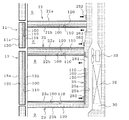
図4は実施の形態1に係る冷蔵庫の要部の側面断面図である。
図5は実施の形態1に係る冷蔵庫の要部の正面断面図である。
図4、図5に示すように、本実施の形態における冷蔵庫1は、箱体2のうち冷凍室群(製氷室6、切替室7、および冷凍室8)の内壁の全面と、仕切壁21、22、23の全面と、扉11、12、13の全面とに、真空断熱材100および蓄冷材110を設けている。
さらに、製氷室6および切替室7の内壁を構成する仕切壁24には、蓄冷材110を設けている。
(Insulation and cold storage structure)
Next, the heat insulation and cold storage structure of the
FIG. 4 is a side cross-sectional view of a main part of the refrigerator according to the first embodiment.
FIG. 5 is a front cross-sectional view of a main part of the refrigerator according to the first embodiment.
As shown in FIGS. 4 and 5, the
Furthermore, a
なお、本実施の形態では、冷凍室群(製氷室6、切替室7、および冷凍室8)の内壁を形成する部分にのみ、真空断熱材100を設ける場合を説明するが、本発明はこれに限るものではない。例えば、箱体2の全面に真空断熱材100を設けるようにしても良い。
また、本実施の形態では、仕切壁21〜23に真空断熱材100を設ける場合を説明するが、本発明はこれに限るものではない。例えば、仕切壁21または仕切壁22の何れか一方に真空断熱材100を設けるようにしても良いし、仕切壁21〜23に加えて仕切壁24にも真空断熱材100を設けても良い。
すなわち、冷凍室8と、この冷凍室8より設定温度帯が高い貯蔵室(冷蔵室5、野菜室9)とを仕切る仕切壁に真空断熱材100を設ける構成であれば良い。
In the present embodiment, the case where the vacuum
Moreover, although this Embodiment demonstrates the case where the vacuum
In other words, the vacuum
なお、ここでは、真空断熱材100を、冷凍室群(製氷室6、切替室7、および冷凍室8)の内壁を構成する箱体2、仕切壁21〜23、および、扉11〜13の全て(背面を除く)の全面に設ける場合を説明するが本発明はこれに限るものではなく、箱体2、仕切壁21〜23、および、扉11〜13の少なくとも1つの任意の位置に設けるようにしても良い。
なお、ここでは、蓄冷材110を、製氷室6、切替室7、および冷凍室8の内壁面の全て(背面を除く)に設ける場合を説明するが本発明はこれに限るものではなく、所望の蓄熱容量に応じて任意の位置に任意の量だけ配置することができる。なお、蓄冷材110に蓄えた冷熱を効率よく庫内に伝達するため、内壁面のうち少なくとも上面(仕切壁21、22)に設けることが望ましい。
Here, the vacuum
In addition, although the case where the
次に、各構成の断熱・蓄冷構造の詳細について説明する。
なお、製氷室6、切替室7および冷凍室8の断熱・蓄冷構造は略同様であるため、冷凍室8を例に説明する。
Next, the details of the heat insulation / cold storage structure of each configuration will be described.
In addition, since the heat insulation and the cold storage structure of the
[箱体]
箱体2は、例えば鋼板により形成された外箱2aと、樹脂材料により形成された内箱2bとの間に断熱材120が設けられている。
箱体2に設けられた真空断熱材100は、内箱2bと断熱材120との間に配置されている。つまり、箱体2に設けられた真空断熱材100は、断熱材120より庫内側(冷凍室8側)に配置されている。
また、箱体2に設けられた蓄冷材110は、真空断熱材100と内箱2bとの間に配置されている。つまり、箱体2に設けられた蓄冷材110は、外箱2aと内箱2bとの間の、真空断熱材100より庫内側(冷凍室8側)に配置されている。
このように、外箱2aと内箱2bとの間には、庫外側から順に、断熱材120、真空断熱材100、蓄冷材110が積層された構造となっている。
なお、蓄冷材110の配置位置は、真空断熱材100より庫内側であれば良く、内箱2bの庫内側表面に配置しても良い。
[Box]
In the
The vacuum
Moreover, the
Thus, between the
In addition, the arrangement | positioning position of the
[仕切壁]
仕切壁22は、例えば樹脂材料により板状に形成され、互いに対向する仕切板22aと仕切板22bの間に、断熱材120が設けられて形成されている。仕切板22aは製氷室6および切替室7側に配置され、仕切板22bは冷凍室8側に配置されている。
仕切壁22に設けられた真空断熱材100は、仕切板22bと断熱材120との間に配置されている。つまり、仕切壁22に設けられた真空断熱材100は、断熱材120より庫内側(冷凍室8側)に配置されている。
また、仕切壁22に設けられた蓄冷材110は、真空断熱材100と仕切板22bとの間に配置されている。つまり、仕切壁22に設けられた蓄冷材110は、一対の仕切板22a、22bの間の、真空断熱材100より庫内側(冷凍室8側)に配置されている。
なお、仕切板22aと断熱材120との間(製氷室6および切替室7側)に、さらに蓄冷材110を設けるようにしても良い。
[Partition wall]
The
The vacuum
Moreover, the
In addition, you may make it provide the
また、仕切壁23も同様に、仕切板23aと仕切板23bとの間に断熱材120が充填されて形成され、仕切板23aと断熱材120との間に真空断熱材100が配置されている。また、真空断熱材100と仕切板23aとの間に蓄冷材110が設けられている。
Similarly, the
このように、仕切壁22、23の一対の仕切板の間には、庫外側から順に、断熱材120、真空断熱材100、蓄冷材110が積層された構造となっている。
なお、蓄冷材110の配置位置は、真空断熱材100より庫内側であれば良く、仕切板22b、23aの庫内側表面に配置しても良い。
なお、仕切壁22の製氷室6および切替室7の庫内側(仕切板22aと断熱材120との間)の全面に、さらに蓄冷材110を設けても良い。
Thus, between the pair of partition plates of the
In addition, the arrangement | positioning position of the
In addition, you may provide the
[扉]
扉13は、庫外側に配置された扉外板13aと、庫内側に配置された扉内板13bとの間に、断熱材120が設けられて形成されている。
扉13に設けられた真空断熱材100は、扉内板13bと断熱材120との間に配置されている。つまり、扉13に設けられた真空断熱材100は、断熱材120より庫内側(冷凍室8側)に配置されている。
また、扉13に設けられた蓄冷材110は、真空断熱材100と扉内板13bとの間に配置されている。つまり、扉13に設けられた蓄冷材110は、真空断熱材100より庫内側(冷凍室8側)に配置されている。
このように、扉外板13aと扉内板13bとの間には、庫外側から順に、断熱材120、真空断熱材100、蓄冷材110が積層された構造となっている。
なお、蓄冷材110の配置位置は、真空断熱材100より庫内側であれば良く、扉内板13bの庫内側表面に配置しても良い。
[door]
The
The vacuum
Moreover, the
Thus, between the door
In addition, the arrangement | positioning position of the
[真空断熱材]
真空断熱材100は、例えば矩形板状に形成された複数の真空断熱パネルを連設して形成される。この真空断熱パネルは、例えば内側からポリエチレンもしくはポリプロピレン等からなる熱溶着層とアルミニウム層および表面保護層をラミネートした二枚のガスバリアフィルムの間に少なくともガラスウールや樹脂などの芯材およびシリカ等の微粉末を挿入し、所定の真空排気装置内において内部を真空とした後、ガスバリアフィルムの縁部を加熱して前記熱溶着層を相互に密着させ密封したものであり、全体として矩形板状を形成している。
なお、真空断熱材100の構造はこれに限るものではなく、外被材の内部を減圧して密封したものであれば良い。
[Vacuum insulation]
The vacuum
In addition, the structure of the vacuum
[蓄冷材]
蓄冷材110は、例えば、相変化(液体・固体間の相変化)による潜熱を冷熱として蓄える潜熱蓄冷材により構成される。この潜熱蓄冷材としては、例えばエチレングリコールを含む水溶液、またはこの水溶液にゲル化剤を添加したゲルを、柔軟性を有する袋状部材に密封して形成する。また例えば、上記潜熱蓄冷材を柔軟性を有しない中空容器内に空気層を設けて密封して形成する。このように潜熱蓄冷材を密封する容器内に空気層を設けることで、凍結により潜熱蓄冷材が体積膨張した場合でも、当該容器の破損を防止することができる。
なお、本実施の形態では蓄冷材110に潜熱蓄冷材を用いる場合を説明するが、本発明はこれに限るものではない。例えば金属や樹脂を用いて顕熱を利用した蓄冷材としても良い。
[Cool storage material]
The
In addition, although this embodiment demonstrates the case where a latent-heat cool storage material is used for the
[断熱材]
断熱材120は、例えばウレタン等に発泡剤が添加され、外箱2aと内箱2bとの間、仕切壁21〜24の一対の仕切板の間、扉10〜14の扉外板と扉内板との間に、それぞれ発泡充填されて形成された発泡断熱材である。
この断熱材120は、真空断熱材100より熱伝導率が高く(熱抵抗が低く)、断熱性が真空断熱材100より低いものである。
[Insulation]
For the
This
なお、本実施の形態の「断熱材120」は、本発明における「充填断熱材」に相当する。
It should be noted that “
このように本実施の形態においては、設定温度帯が氷点下以下である冷凍室群(製氷室6、切替室7、および冷凍室8)の内壁の両側面の全面と、扉11〜13の全面とに真空断熱材100を設けている。また、冷凍室群より設定温度帯が高い冷蔵室5および野菜室9と、冷凍室群とを仕切る仕切壁21および仕切壁23に、全面に亘って真空断熱材100を設けている。このため、冷蔵庫1の庫外から冷凍室群への熱進入(冷凍室群内の冷熱の熱移動)を抑制することができる。さらに、冷凍室群より設定温度帯が高い貯蔵室から冷凍室群への熱進入を抑制することができる。
また、冷凍室群の内壁面に蓄冷材110を設けているので、冷凍室群の冷熱を蓄えることができる。例えば冷却能力の低下や運転停止、扉の開閉などにより、庫内温度が上昇した場合であっても、蓄冷材110に蓄えられた冷熱により庫内を冷却することができる。よって、冷凍室群内の温度変動を低減することができる。
また、蓄冷材110を冷凍室群の内壁に設けているので、冷熱を蓄えるための蓄冷槽や蓄冷槽を冷却するための冷却手段を別途設ける必要がなく、簡易な構成で冷熱を蓄えることができる。また、貯蔵室とは別個の蓄冷室を設ける必要がなく、冷蔵庫1の本体に対する貯蔵室の庫内容量を低減させずに冷熱を蓄えることができる。
As described above, in the present embodiment, the entire surface of both sides of the inner wall of the freezing room group (the
Moreover, since the
Moreover, since the
また本実施の形態においては、冷凍室群の庫外側から庫内側へ順に、断熱材120、真空断熱材100、蓄冷材110が積層された構造となっている。
このように、蓄冷材110を真空断熱材100より庫内側に配置したことで、庫内の冷熱が真空断熱材100により断熱されることなく、蓄冷材110に冷熱を蓄えることができる。また、蓄冷材110に蓄えられた冷熱が庫外側(冷蔵室側)へ熱移動することを抑制することができる。
また、真空断熱材100を断熱材120より庫内側に配置したことで、庫内の冷熱が断熱材120へ熱移動することを抑制することができる。断熱材120は真空断熱材100よりも熱伝導率が高く断熱性が低い。このため、仮に、断熱材120を真空断熱材100より庫内側に配置した場合、庫内の冷熱が断熱材120へ熱移動して断熱材120の冷却に消費されることとなる。例えば冷却能力の低下や運転停止、扉の開閉などにより、庫内温度が上昇した場合には、これに伴い断熱材120も温度上昇し、庫内の冷却に必要となる冷熱が増加することとなる。
また、蓄冷材110を、外箱2aと内箱2bとの間、仕切壁の一対の仕切板の間、扉内板と扉外板との間に配置している。このため、蓄冷材110が庫内側に露出することがない。例えば、蓄冷材110を液体やゲル材を袋状のシートに密封して形成した場合であっても、シートが損傷して内容物が漏洩することを防止することができる。また、蓄冷材110が使用者に視認されることがなく、意匠性を向上することができる。
Moreover, in this Embodiment, it has the structure where the
As described above, the
Moreover, it can suppress that the cold heat in a store | warehouse | chamber heat-transfers to the
Moreover, the
なお、上記の構成に加え、冷凍室群の内壁面を構成する隔壁25のうち、流入口および流出口以外の全面に、真空断熱材100および蓄冷材110を設けるようにしても良い。
このような構成の例を図6に示す。
図6においては、上述した構成に加え、冷凍室8の隔壁25の庫内側(前面側)の、流入口281および流出口282以外の全面に真空断熱材100を設けている。
このような構成により、冷凍室8は、流入口281および流出口282以外の略全ての面について真空断熱材100で覆われることとなる。よって、冷蔵庫1の庫外から冷凍室群への熱進入と、冷凍室8より設定温度帯が高い貯蔵室から冷凍室8への熱進入を抑制することができると共に、冷蔵庫1の背面側から冷凍室8への熱進入も抑制することができる。例えば、冷却運転を停止し冷却器室30の温度が上昇した場合においてこの効果は顕著である。
In addition to the above configuration, the vacuum
An example of such a configuration is shown in FIG.
6, in addition to the above-described configuration, the vacuum
With such a configuration, the
また、図6においては、冷凍室8の隔壁25に設けた真空断熱材100より庫内側の、流入口281および流出口282以外の全面に蓄冷材110を設けている。
このような構成により、冷凍室8の背面壁に冷熱を蓄えることができ、庫内温度が上昇した場合であっても、蓄冷材110の蓄えられた冷熱により庫内を背面側から冷却することができる。
なお、図6の例では、冷凍室8の隔壁25に真空断熱材100および蓄冷材110を設けた場合を説明したが、製氷室6や切替室7の隔壁25にも設けても良い。また、所望の蓄熱容量に応じて、隔壁25に設ける蓄冷材110を省略しても良い。
なお、蓄冷材110の配置位置は、真空断熱材100より庫内側であれば良く、隔壁25の庫内側表面に配置しても良い。
Further, in FIG. 6, the
With such a configuration, cold heat can be stored on the back wall of the
In the example of FIG. 6, the case where the vacuum
In addition, the arrangement | positioning position of the
なお、本実施の形態では、冷凍室群(製氷室6、切替室7、および冷凍室8)の内壁に真空断熱材100および蓄冷材110を設ける場合を説明したが、本発明はこれに限らず、冷凍室群以外の貯蔵室の内壁にも真空断熱材100および蓄冷材110を設ける構成としても良い。
例えば、冷蔵室5と野菜室9のそれぞれについて、上述した冷凍室群と同様に、冷蔵室5および野菜室9の内壁の両側面の全面と、扉10、14の全面とに真空断熱材100を設けるようにしても良い。また、冷蔵室5および野菜室9の内壁面うち少なくとも上面に蓄冷材110を設けるようにしても良い。そして、庫外側から庫内側へ順に、断熱材120、真空断熱材100、蓄冷材110が積層された構造とするようにしても良い。
このような構成においても、当該貯蔵室の庫外から庫内への熱進入を抑制することができる。また、庫内の冷熱が真空断熱材100により断熱されることなく、蓄冷材110に冷熱を蓄えることができる。
In the present embodiment, the case where the vacuum
For example, for each of the
Even in such a configuration, it is possible to suppress heat intrusion from the outside of the storage chamber to the inside of the warehouse. Further, the cold energy in the refrigerator can be stored in the
(収納容器)
次に、貯蔵室内に配置された収納容器50と載置棚40の構造について説明する。
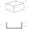
図7は実施の形態1に係る収納容器の構成を示す図である。
図7(a)は収納容器50の外観斜視図であり、図7(b)は収納容器50の側面断面図である。
図7に示すように、本実施の形態における収納容器50は、例えば樹脂材料により上面が開口した箱状に形成されており、内部に食品などの被冷却物や、他の収納容器50や載置棚40(後述)などが収納される。
この収納容器50は、中空二重構造を有しており、内部に蓄冷材110を封入して構成されている。
(Storage container)
Next, the structure of the
FIG. 7 is a diagram showing the configuration of the storage container according to
FIG. 7A is an external perspective view of the
As shown in FIG. 7, the
The
このような構成により、蓄冷材110を被冷却物のより近くに配置することが可能となる。よって、被冷却物を冷却するのに必要な蓄熱容量を少なくすることが可能となる。
また、蓄冷材110を収納容器50の内部に設けているので、冷熱を蓄えるための蓄冷槽や蓄冷槽を冷却するための冷却手段を別途設ける必要がなく、簡易な構成で冷熱を蓄えることができる。
また、樹脂製の収納容器50の内部に蓄冷材110を封入することで、蓄冷材110として液体やゲル材を用いた場合であっても、蓄冷材110の漏洩を防止することができる。
With such a configuration, the
Moreover, since the
Moreover, even if it is a case where a liquid and a gel material are used as the
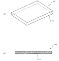
図8は実施の形態1に係る載置棚の構成を示す図である。
図8(a)は載置棚40の外観斜視図であり、図8(b)は載置棚40の側面断面図である。
図8に示すように、本実施の形態における載置棚40は、例えば樹脂材料により板状に形成されており、上面に食品などの被冷却物が載置される。
この載置棚40は、中空二重構造を有しており、内部に蓄冷材110を封入して構成されている。
FIG. 8 is a diagram illustrating the configuration of the mounting shelf according to the first embodiment.
FIG. 8A is an external perspective view of the mounting
As shown in FIG. 8, the mounting
The mounting
このような構成により、蓄冷材110を被冷却物のより近くに配置することが可能となる。よって、被冷却物を冷却するのに必要な蓄熱容量を少なくすることが可能となる。
また、蓄冷材110を載置棚40の内部に設けているので、冷熱を蓄えるための蓄冷槽や蓄冷槽を冷却するための冷却手段を別途設ける必要がなく、簡易な構成で冷熱を蓄えることができる。
また、樹脂製の載置棚40の内部に蓄冷材110を封入することで、蓄冷材110として液体やゲル材を用いた場合であっても、蓄冷材110の漏洩を防止することができる。
With such a configuration, the
Moreover, since the
Moreover, even if it is a case where a liquid and a gel material are used as the
(潜熱蓄冷材の凝固点)
次に、蓄冷材110として潜熱蓄冷材を用いた場合の凝固点と、貯蔵室の設定温度との関係について説明する。
(Freezing point of latent heat storage material)
Next, the relationship between the freezing point when a latent heat regenerator material is used as the
潜熱蓄冷材の凝固点は、当該潜熱蓄冷材を設けた貯蔵室の設定温度帯の下限値より高い温度である。
例えば上述したように、冷凍室8の設定温度帯は、約−16℃〜−22℃に設定可能となっている。この場合、冷凍室8の内壁面(箱体2、仕切壁22、23、扉13)に設けた蓄冷材110、並びに、冷凍室8内に配置した収納容器50および載置棚40内の蓄冷材110には、設定温度帯の上限値である約−16℃より高い温度に凝固点を持つ潜熱蓄冷材を用いる。
このように、潜熱蓄冷材の凝固点が設定温度帯の上限値より高いことで、貯蔵室の冷却運転によって、潜熱蓄冷材を凝固させることが可能となり、潜熱蓄冷材における液体・固体間の相変化に伴う潜熱を冷熱として蓄えることができる。
The freezing point of the latent heat regenerator material is a temperature higher than the lower limit value of the set temperature range of the storage room provided with the latent heat regenerator material.
For example, as described above, the set temperature zone of the
As described above, the freezing point of the latent heat storage material is higher than the upper limit value of the set temperature zone, so that the latent heat storage material can be solidified by the cooling operation of the storage chamber, and the phase change between liquid and solid in the latent heat storage material The latent heat that accompanies can be stored as cold.
また、冷凍室群(製氷室6、切替室7、および冷凍室8)に設けた潜熱蓄冷材の凝固点は、当該貯蔵室の目標設定温度より高く、0℃以下の温度である。
例えば通常の冷却運転時において、冷凍室8内の目標設定温度が−18℃となるように冷却運転を制御する場合、この冷凍室8内の蓄冷材110には、凝固点が−15℃の潜熱蓄冷材を用いる。この潜熱蓄冷材の蓄熱量特性を図9に示す。
Moreover, the freezing point of the latent heat regenerator material provided in the freezer group (the
For example, when the cooling operation is controlled so that the target set temperature in the
図9は実施の形態1に係る潜熱蓄冷材の蓄熱量特性を示す図である。
図9においては、0℃を基準にして、横軸は温度差を示し、縦軸は潜熱蓄冷材の蓄熱量を示している。なお、図9に示す特性の傾きは比熱に相当する。
図9に示すように、潜熱蓄冷材は、凝固点(−15℃)において、相変化に伴う潜熱により温度変化することなく、熱量の吸熱または放熱が行われる。例えば凝固した潜熱蓄冷材が温度上昇する際には、凝固点においては温度上昇することなく潜熱に相当する熱量が吸熱されることとなる。
FIG. 9 is a diagram showing a heat storage amount characteristic of the latent heat cool storage material according to the first embodiment.
In FIG. 9, on the basis of 0 ° C., the horizontal axis indicates the temperature difference, and the vertical axis indicates the heat storage amount of the latent heat storage material. The slope of the characteristic shown in FIG. 9 corresponds to specific heat.
As shown in FIG. 9, the latent heat regenerator material absorbs heat or releases heat at the freezing point (−15 ° C.) without changing the temperature due to the latent heat accompanying the phase change. For example, when the temperature of the solidified latent heat regenerator material increases, the amount of heat corresponding to the latent heat is absorbed without increasing the temperature at the freezing point.
このように本実施の形態においては、冷凍室群に設けた潜熱蓄冷材の凝固点を、目標設定温度(−18℃)より高く、0℃以下の温度(−15℃)としている。これにより、冷凍室群の庫内温度が上昇した場合であっても、潜熱蓄冷材は凝固点(−15℃)まで上昇したあと、この温度を保ったまま潜熱に相当する熱量を庫内から吸熱して相変化し、そのあと温度が上昇することとなる。よって、例えば冷却能力の低下や運転停止などにより、庫内温度が上昇した場合であっても、冷凍室群内の温度を、一定時間の間、0℃以下の凝固点付近の温度に保つことができる。 Thus, in the present embodiment, the freezing point of the latent heat storage material provided in the freezer compartment group is set to a temperature (−15 ° C.) higher than the target set temperature (−18 ° C.) and 0 ° C. As a result, even if the internal temperature of the freezer compartment rises, the latent heat regenerator material rises to the freezing point (−15 ° C.) and then absorbs the amount of heat corresponding to the latent heat while maintaining this temperature. Phase change, and then the temperature rises. Therefore, even if the internal temperature rises due to, for example, a decrease in cooling capacity or operation stop, the temperature in the freezer compartment can be kept at a temperature near the freezing point of 0 ° C. or lower for a certain period of time. it can.
なお、設定温度帯が0℃以上の冷蔵室5および野菜室9の内壁面に蓄冷材110を設ける場合、並びに、冷蔵室5や野菜室9内に収納容器50や載置棚40を配置する場合、これらの蓄冷材110には、凝固点が、0℃より高く、当該貯蔵室の設定温度帯の上限値より高い温度の潜熱蓄冷材を用いる。
例えば上述したように、冷蔵室5の設定温度帯は、約0℃〜4℃に設定可能となっている。この場合、冷蔵室5の内壁面(箱体2、仕切壁21、扉10)に設けた蓄冷材110、並びに、冷蔵室5内に配置した収納容器50および載置棚40内の蓄冷材110には、設定温度帯の上限値である約4℃より高い温度(例えば5℃)に凝固点を持つ潜熱蓄冷材を用いる。
これにより、例えば冷却能力の低下や運転停止などにより、庫内温度が上昇した場合であっても、冷蔵室5や野菜室9内の温度を、一定時間の間、0℃より高い凝固点付近の温度に保つことができる。また、庫内の温度が0℃以下となることがないため、冷蔵室5や野菜室9内の被冷却物が凍結することを防止することができる。
In addition, when providing the
For example, as described above, the set temperature zone of the
Thereby, even if the inside temperature rises due to, for example, a decrease in cooling capacity or operation stoppage, the temperature in the
(冷却運転動作)
次に、所定の時間帯において、冷蔵庫1の消費電力を低減する冷却運転動作について説明する。
(Cooling operation)
Next, the cooling operation operation for reducing the power consumption of the
本実施の形態における冷蔵庫1の制御回路は、所定の時間帯において、冷却運転を停止または冷却能力を低下させる。この所定の時間帯としては、例えば昼間など商用電力の電力需要がピークとなる時間帯を含む時間帯とする。
なお、所定の時間帯は、予め制御回路に設定するようにしても良いし、季節に応じて時間帯を変更するようにしても良い。
なお、所定の時間帯の設定はこれに限るものではなく、使用者による操作によって任意の時間に設定するようにしても良いし、外部機器から設定情報を入力するようにしても良い。
ここでは、例えば、予め設定された昼間の時間帯に冷却運転を停止し、夜間の時間帯には貯蔵室内の温度が目標とする設定温度となるように冷却運転(通常運転)を行う。
このような動作による冷凍室8の庫内温度と時間経過との関係を図10により説明する。
The control circuit of the
Note that the predetermined time zone may be set in the control circuit in advance, or the time zone may be changed according to the season.
The setting of the predetermined time zone is not limited to this, and it may be set at an arbitrary time by an operation by the user, or setting information may be input from an external device.
Here, for example, the cooling operation is stopped in a preset daytime period, and the cooling operation (normal operation) is performed so that the temperature in the storage chamber becomes a target set temperature in the nighttime period.
The relationship between the internal temperature of the
図10は実施の形態1に係る冷蔵庫の庫内温度の変化を説明する図である。
図10においては、横軸は経過時間を示し、縦軸は冷凍室8内の庫内温度を示している。なお、図10の例では、蓄冷材110には凝固点が−15℃の潜熱蓄冷材を用いている。
図10に示すように、夜間の時間帯には、冷凍室8内の目標温度が−18℃となるように冷却運転が行われる(通常運転)。これにより、冷凍室8内の温度は約−18℃に保たれると共に、潜熱蓄冷材は凝固して冷熱が潜熱として蓄冷される。
次に、昼間の時間帯には、冷却運転が停止される。これにより、冷凍室8内の温度は徐々に上昇し、潜熱蓄冷材の凝固点である−15℃まで上昇する。そして、潜熱蓄冷材この温度を保ったまま潜熱に相当する熱量を庫内から吸熱(冷熱を放出)して相変化する。これにより、一定時間の間、冷凍室8内の温度が約−15℃に保たれる。
潜熱蓄冷材が潜熱に相当する熱量を吸収して相変化したあと、冷凍室8内の温度は徐々に上昇する。
そして、夜間の時間帯には、再度、通常運転が行われ冷凍室8内の温度が目標温度となるように冷却される。
FIG. 10 is a diagram for explaining a change in the internal temperature of the refrigerator according to the first embodiment.
In FIG. 10, the horizontal axis indicates the elapsed time, and the vertical axis indicates the internal temperature in the
As shown in FIG. 10, during the night time period, the cooling operation is performed so that the target temperature in the
Next, the cooling operation is stopped during the daytime. Thereby, the temperature in the
After the latent heat storage material absorbs the amount of heat corresponding to the latent heat and undergoes a phase change, the temperature in the
Then, during the night time zone, normal operation is performed again, and the temperature in the
このように本実施の形態においては、所定の時間帯において、冷却運転を停止または冷却能力を低下させるので、当該時間帯における冷蔵庫1の消費電力量を低減することができる。また、冷凍室群の内壁の両側面の全面と、冷凍室群と他の貯蔵室とを仕切壁の全面と、扉の全面とに真空断熱材100を設けているので、冷凍室群の庫内から庫外への冷熱の熱移動、および、冷凍室群から他の貯蔵室への冷熱の熱移動を抑制することができ、冷却運転を停止または冷却能力を低下させた場合であっても、当該時間帯における冷凍室群の温度上昇を軽減することができる。
また、真空断熱材100より庫内側に配置した蓄冷材110により、庫内の冷熱が真空断熱材100により断熱されることなく冷熱を蓄えているので、冷却運転を停止または冷却能力を低下させた場合であっても、冷凍室群の蓄冷材110に蓄えられた冷熱が庫外や他の貯蔵室へ熱移動することを抑制しつつ、冷凍室群内を冷却することができる。よって、当該時間帯における冷凍室群の温度上昇を抑制することができる。
また、蓄冷材110として潜熱蓄冷材を用いているため、冷却運転を停止または冷却能力を低下させた場合であっても、冷凍室群内の温度を、一定時間の間、凝固点付近の温度に保つことができる。
As described above, in the present embodiment, the cooling operation is stopped or the cooling capacity is reduced in a predetermined time zone, so that the power consumption of the
In addition, the
Moreover, since the latent heat regenerator material is used as the
また本実施の形態においては、商用電力の電力需要がピークとなる時間帯において、冷却運転を停止または冷却能力を低下させるので、電力需要がピークとなる時間帯における冷蔵庫1の消費電力量を低減することができる。
Further, in the present embodiment, the cooling operation is stopped or the cooling capacity is reduced in the time zone when the power demand for commercial power is at a peak, so the power consumption of the
1 冷蔵庫、2 箱体、2a 外箱、2b 内箱、5 冷蔵室、6 製氷室、7 切替室、8 冷凍室、9 野菜室、10 扉、11 扉、12 扉、13 扉、13a 扉外板、13b 扉内板、14 扉、21 仕切壁、22 仕切壁、22a 仕切板、22b 仕切板、23 仕切壁、23a 仕切板、23b 仕切板、24 仕切壁、25 隔壁、30 冷却器室、31 圧縮機、32 冷却器、33 送風機、40 載置棚、50 収納容器、100 真空断熱材、110 蓄冷材、120 断熱材、200 風路、201 背面風路、202 戻り口、251 流入口、252 流出口、261 流入口、262 流出口、271 流入口、272 流出口、281 流入口、282 流出口、291a 流入口、291b 流入口、292a 流出口、292b 流出口。 1 refrigerator, 2 box, 2a outer box, 2b inner box, 5 refrigerator compartment, 6 ice making room, 7 switching room, 8 freezer room, 9 vegetable room, 10 door, 11 door, 12 door, 13 door, 13a outside door Plate, 13b door inner plate, 14 door, 21 partition wall, 22 partition wall, 22a partition plate, 22b partition plate, 23 partition wall, 23a partition plate, 23b partition plate, 24 partition wall, 25 partition wall, 30 cooler chamber, 31 compressor, 32 cooler, 33 blower, 40 mounting shelf, 50 storage container, 100 vacuum heat insulating material, 110 cold storage material, 120 heat insulating material, 200 air passage, 201 back air passage, 202 return port, 251 inlet, 252 outlet, 261 inlet, 262 outlet, 271 inlet, 272 outlet, 281 inlet, 282 outlet, 291a inlet, 291b inlet, 292a outlet, 292b Outlet.
Claims (10)
互いに対向する一対の仕切板と、該一対の仕切板の間に設けられた充填断熱材とにより形成され、前記箱体の内部空間を複数の貯蔵室に仕切る仕切壁と、
扉内板および扉外板と、該扉内板と扉外板との間に設けられた充填断熱材とにより形成され、前記各貯蔵室の前面開口部に設けられた扉と
を備え、
前記貯蔵室は、複数の冷凍室と、前記冷凍室より設定温度帯が高い1つまたは複数の冷蔵室とを有し、
前記冷凍室と前記冷蔵室とを仕切る前記仕切壁の全面と、複数の前記冷凍室のそれぞれの間を仕切る前記仕切壁の全面と、前記箱体のうち前記冷凍室の内壁の全面と、前記冷凍室に設けられた前記扉の全面とに、真空断熱材と蓄冷材とを、前記充填断熱材と積層して設け、
前記蓄冷材を、前記真空断熱材及び前記充填断熱材より庫内側に配置し、
前記真空断熱材を、前記充填断熱材より庫内側に配置し、
前記充填断熱材は、前記真空断熱材より熱伝導率が高い
ことを特徴とする冷蔵庫。 A box body in which a filling heat insulating material is provided between the outer box forming the outer shell of the refrigerator main body and the inner box forming the inner wall of the main body, and the front side is opened,
A partition wall formed by a pair of partition plates facing each other and a filling heat insulating material provided between the pair of partition plates, and partitioning the internal space of the box into a plurality of storage chambers;
Formed by a door inner plate and a door outer plate, and a filling heat insulating material provided between the door inner plate and the door outer plate, and provided with a door provided at the front opening of each storage chamber,
The storage room has a plurality of freezer rooms, and one or a plurality of refrigerator rooms having a set temperature zone higher than the freezer room,
The entire surface of the partition wall that partitions the freezer compartment and the refrigerator compartment, the entire surface of the partition wall that partitions each of the plurality of freezer compartments, the entire surface of the inner wall of the freezer compartment of the box, On the entire surface of the door provided in the freezer compartment , a vacuum heat insulating material and a cold storage material are laminated with the filled heat insulating material,
The cold storage material is disposed on the inner side of the vacuum heat insulating material and the filled heat insulating material,
The vacuum heat insulating material is disposed on the inner side of the filled heat insulating material,
The filling heat insulating material has a higher thermal conductivity than the vacuum heat insulating material.
前記冷却器を配置する冷却器室と前記貯蔵室とを仕切る隔壁と
を備え、
前記隔壁は、前記冷却器からの冷気を前記貯蔵室内に流入する流入口と、前記冷気を前記貯蔵室から前記冷却器室へ流出する流出口とを有し、
前記冷凍室の内壁面を構成する前記隔壁のうち、前記流入口および前記流出口以外の全面に、前記真空断熱材および前記蓄冷材を設けた
ことを特徴とする請求項1記載の冷蔵庫。 A cooler disposed on the back side of the storage room;
A partition that partitions the cooler chamber in which the cooler is disposed and the storage chamber;
The partition wall has an inflow port for flowing cool air from the cooler into the storage chamber, and an outflow port for flowing out the cool air from the store chamber to the cooler chamber,
Among the partition walls constituting the inner wall surface of said freezing chamber, said inlet and on the entire surface other than the outlet, refrigerator according to claim 1, characterized by providing the vacuum heat insulating material and the cold accumulating material.
ことを特徴とする請求項1または2記載の冷蔵庫。 And the entire surface of the inner wall of the cooling chamber of the box body, according to claim 1, wherein said providing the entire surface of the door provided in the refrigerating chamber, the vacuum heat insulating material and the cold accumulating material Refrigerator.
前記収納容器は、中空二重構造を有し、内部に蓄冷材を封入した
ことを特徴とする請求項1〜3の何れか1項に記載の冷蔵庫。 A storage container that is disposed in the storage chamber and stores an object to be cooled;
The refrigerator according to any one of claims 1 to 3 , wherein the storage container has a hollow double structure, and a regenerator material is enclosed therein.
前記載置棚は、中空二重構造を有し、内部に蓄冷材を封入した
ことを特徴とする請求項1〜4の何れか1項に記載の冷蔵庫。 It is disposed in the storage chamber, and includes a mounting shelf on which an object to be cooled is mounted.
The refrigerator according to any one of claims 1 to 4 , wherein the storage shelf has a hollow double structure, and a regenerator material is enclosed therein.
前記潜熱蓄冷材の凝固点は、当該潜熱蓄冷材を設けた前記貯蔵室の設定温度帯の上限値より高い温度である
ことを特徴とする請求項1〜5の何れか1項に記載の冷蔵庫。 The cold storage material is constituted by a latent heat cold storage material that stores latent heat due to phase change as cold heat,
The freezing point of latent heat storage material is refrigerator according to any one of claim 1 to 5, characterized in that a higher than the upper limit of the set temperature range of the storage compartment provided with the latent heat storage material temperature.
ことを特徴とする請求項6記載の冷蔵庫。 The freezing point of the latent heat storage material provided in the refrigerating compartment is higher than the target set temperature of the freezing chamber, the refrigerator 請 Motomeko 6 wherein you characterized in that the temperature of 0 ℃ or less.
ことを特徴とする請求項6または7記載の冷蔵庫。 Freezing point of the latent heat storage material provided in the refrigerating chamber, 0 ° C. higher than the refrigerator 請 Motomeko 6 or 7, wherein you wherein a temperature higher than the upper limit of the set temperature range of the refrigerating compartment .
前記制御手段は、所定の時間帯において、冷却運転を停止または冷却能力を低下させる
ことを特徴とする請求項1〜8の何れか1項に記載の冷蔵庫。 Comprising control means for controlling the cooling operation of the refrigerator,
The refrigerator according to any one of claims 1 to 8 , wherein the control means stops the cooling operation or lowers the cooling capacity in a predetermined time zone.
ことを特徴とする請求項9記載の冷蔵庫。 The refrigerator according to claim 9, wherein the predetermined time period includes a time period in which the power demand of commercial power reaches a peak.
Priority Applications (1)
| Application Number | Priority Date | Filing Date | Title |
|---|---|---|---|
| JP2011116293A JP5800575B2 (en) | 2011-05-24 | 2011-05-24 | refrigerator |
Applications Claiming Priority (1)
| Application Number | Priority Date | Filing Date | Title |
|---|---|---|---|
| JP2011116293A JP5800575B2 (en) | 2011-05-24 | 2011-05-24 | refrigerator |
Publications (2)
| Publication Number | Publication Date |
|---|---|
| JP2012242072A JP2012242072A (en) | 2012-12-10 |
| JP5800575B2 true JP5800575B2 (en) | 2015-10-28 |
Family
ID=47463966
Family Applications (1)
| Application Number | Title | Priority Date | Filing Date |
|---|---|---|---|
| JP2011116293A Active JP5800575B2 (en) | 2011-05-24 | 2011-05-24 | refrigerator |
Country Status (1)
| Country | Link |
|---|---|
| JP (1) | JP5800575B2 (en) |
Families Citing this family (10)
| Publication number | Priority date | Publication date | Assignee | Title |
|---|---|---|---|---|
| CN103453722A (en) * | 2013-08-07 | 2013-12-18 | 宁波绿凯节能科技有限公司 | Refrigerator with partition of phase change material |
| JP6553922B2 (en) * | 2015-04-07 | 2019-07-31 | 日立グローバルライフソリューションズ株式会社 | refrigerator |
| JP6689415B2 (en) * | 2017-01-16 | 2020-04-28 | 三菱電機株式会社 | refrigerator |
| SG11202000392PA (en) * | 2017-09-01 | 2020-03-30 | Mitsubishi Electric Corp | Refrigerator |
| AU2017430066B2 (en) * | 2017-09-01 | 2020-11-05 | Mitsubishi Electric Corporation | Refrigerator |
| JP7335681B2 (en) | 2018-03-14 | 2023-08-30 | 東芝ライフスタイル株式会社 | refrigerator |
| CN112204327B (en) * | 2018-05-25 | 2022-04-22 | 普和希控股公司 | Heat insulation structure of cooling device and cooling device |
| JP6975699B2 (en) * | 2018-10-18 | 2021-12-01 | 日立グローバルライフソリューションズ株式会社 | refrigerator |
| JP7493305B2 (en) | 2019-01-23 | 2024-05-31 | 日立グローバルライフソリューションズ株式会社 | refrigerator |
| WO2020165938A1 (en) * | 2019-02-12 | 2020-08-20 | 三菱電機株式会社 | Temperature determination device, temperature determination program, and temperature determination method |
Family Cites Families (13)
| Publication number | Priority date | Publication date | Assignee | Title |
|---|---|---|---|---|
| JPH044679U (en) * | 1990-04-20 | 1992-01-16 | ||
| JP3811963B2 (en) * | 1995-03-09 | 2006-08-23 | 株式会社日立製作所 | refrigerator |
| JPH09287863A (en) * | 1996-04-18 | 1997-11-04 | Matsushita Refrig Co Ltd | Refrigerator |
| JPH09318242A (en) * | 1996-05-31 | 1997-12-12 | Matsushita Refrig Co Ltd | Refrigerator |
| JPH11142046A (en) * | 1997-11-11 | 1999-05-28 | Sanyo Electric Co Ltd | Heat insulation wall |
| JP2000088421A (en) * | 1998-09-18 | 2000-03-31 | Hitachi Ltd | Refrigerator |
| JP3502312B2 (en) * | 1999-11-02 | 2004-03-02 | 松下冷機株式会社 | Separable refrigerator |
| JP4073160B2 (en) * | 2000-10-31 | 2008-04-09 | 三洋電機株式会社 | Cooling storage |
| JP3478810B2 (en) * | 2001-01-15 | 2003-12-15 | 松下冷機株式会社 | Insulated box, raw material manufacturing method, and refrigerator |
| JP2006329482A (en) * | 2005-05-24 | 2006-12-07 | Toshiba Corp | Refrigerator |
| JP2007240021A (en) * | 2006-03-06 | 2007-09-20 | Matsushita Electric Ind Co Ltd | Folding-type cool box |
| JP2008116161A (en) * | 2006-11-07 | 2008-05-22 | Matsushita Electric Ind Co Ltd | Refrigerator |
| JP4931880B2 (en) * | 2008-08-12 | 2012-05-16 | 三菱電機株式会社 | Cold storage panel and freezer / refrigerator equipped with the same |
-
2011
- 2011-05-24 JP JP2011116293A patent/JP5800575B2/en active Active
Also Published As
| Publication number | Publication date |
|---|---|
| JP2012242072A (en) | 2012-12-10 |
Similar Documents
| Publication | Publication Date | Title |
|---|---|---|
| JP5558415B2 (en) | refrigerator | |
| JP5800575B2 (en) | refrigerator | |
| JP5409704B2 (en) | refrigerator | |
| US9624022B2 (en) | Storage container utilizing two different heat insulating materials in combination with a temperature control unit and a heat storage material placed within the container | |
| TWI639803B (en) | Cold storage | |
| KR101544452B1 (en) | Refrigerator with heat conduction sheet | |
| KR20120022600A (en) | Refrigerator | |
| CN103339454B (en) | Freezer | |
| WO2011114656A1 (en) | Refrigerator | |
| JP2008298360A (en) | Heat insulation case body for cooling storage | |
| JP5843483B2 (en) | refrigerator | |
| JP2006329482A (en) | Refrigerator | |
| JP5800576B2 (en) | refrigerator | |
| JPH10253244A (en) | Refrigerator | |
| JP2002364978A (en) | Refrigerator | |
| JP2018025323A (en) | refrigerator | |
| JP2003222466A (en) | Refrigerator | |
| JPH10205994A (en) | Heat insulation box body of cooling storage | |
| JP6492291B2 (en) | refrigerator | |
| JPH10205989A (en) | Refrigerator | |
| JPH10205995A (en) | Refrigerator | |
| JP2008002694A (en) | Refrigerator | |
| CN115077166A (en) | Refrigerator with a door | |
| JP2010025506A (en) | Refrigerator | |
| JP2008202882A (en) | Refrigerator |
Legal Events
| Date | Code | Title | Description |
|---|---|---|---|
| A621 | Written request for application examination |
Free format text: JAPANESE INTERMEDIATE CODE: A621 Effective date: 20121228 |
|
| A977 | Report on retrieval |
Free format text: JAPANESE INTERMEDIATE CODE: A971007 Effective date: 20130927 |
|
| A131 | Notification of reasons for refusal |
Free format text: JAPANESE INTERMEDIATE CODE: A131 Effective date: 20131029 |
|
| A521 | Request for written amendment filed |
Free format text: JAPANESE INTERMEDIATE CODE: A523 Effective date: 20131227 |
|
| A02 | Decision of refusal |
Free format text: JAPANESE INTERMEDIATE CODE: A02 Effective date: 20140520 |
|
| A521 | Request for written amendment filed |
Free format text: JAPANESE INTERMEDIATE CODE: A523 Effective date: 20140820 |
|
| A911 | Transfer to examiner for re-examination before appeal (zenchi) |
Free format text: JAPANESE INTERMEDIATE CODE: A911 Effective date: 20140902 |
|
| A912 | Re-examination (zenchi) completed and case transferred to appeal board |
Free format text: JAPANESE INTERMEDIATE CODE: A912 Effective date: 20141107 |
|
| A61 | First payment of annual fees (during grant procedure) |
Free format text: JAPANESE INTERMEDIATE CODE: A61 Effective date: 20150825 |
|
| R150 | Certificate of patent or registration of utility model |
Ref document number: 5800575 Country of ref document: JP Free format text: JAPANESE INTERMEDIATE CODE: R150 |
|
| R250 | Receipt of annual fees |
Free format text: JAPANESE INTERMEDIATE CODE: R250 |
|
| R250 | Receipt of annual fees |
Free format text: JAPANESE INTERMEDIATE CODE: R250 |
|
| R250 | Receipt of annual fees |
Free format text: JAPANESE INTERMEDIATE CODE: R250 |
|
| R250 | Receipt of annual fees |
Free format text: JAPANESE INTERMEDIATE CODE: R250 |
|
| R250 | Receipt of annual fees |
Free format text: JAPANESE INTERMEDIATE CODE: R250 |
|
| R250 | Receipt of annual fees |
Free format text: JAPANESE INTERMEDIATE CODE: R250 |