WO2012176477A1 - Power conditioner, control method and power generation system - Google Patents
Power conditioner, control method and power generation system Download PDFInfo
- Publication number
- WO2012176477A1 WO2012176477A1 PCT/JP2012/004082 JP2012004082W WO2012176477A1 WO 2012176477 A1 WO2012176477 A1 WO 2012176477A1 JP 2012004082 W JP2012004082 W JP 2012004082W WO 2012176477 A1 WO2012176477 A1 WO 2012176477A1
- Authority
- WO
- WIPO (PCT)
- Prior art keywords
- switch
- power
- converter
- direct current
- commercial power
- Prior art date
Links
Images


Classifications
-
- H—ELECTRICITY
- H02—GENERATION; CONVERSION OR DISTRIBUTION OF ELECTRIC POWER
- H02M—APPARATUS FOR CONVERSION BETWEEN AC AND AC, BETWEEN AC AND DC, OR BETWEEN DC AND DC, AND FOR USE WITH MAINS OR SIMILAR POWER SUPPLY SYSTEMS; CONVERSION OF DC OR AC INPUT POWER INTO SURGE OUTPUT POWER; CONTROL OR REGULATION THEREOF
- H02M7/00—Conversion of ac power input into dc power output; Conversion of dc power input into ac power output
- H02M7/66—Conversion of ac power input into dc power output; Conversion of dc power input into ac power output with possibility of reversal
-
- H—ELECTRICITY
- H02—GENERATION; CONVERSION OR DISTRIBUTION OF ELECTRIC POWER
- H02J—CIRCUIT ARRANGEMENTS OR SYSTEMS FOR SUPPLYING OR DISTRIBUTING ELECTRIC POWER; SYSTEMS FOR STORING ELECTRIC ENERGY
- H02J1/00—Circuit arrangements for dc mains or dc distribution networks
- H02J1/10—Parallel operation of dc sources
- H02J1/102—Parallel operation of dc sources being switching converters
-
- H—ELECTRICITY
- H02—GENERATION; CONVERSION OR DISTRIBUTION OF ELECTRIC POWER
- H02J—CIRCUIT ARRANGEMENTS OR SYSTEMS FOR SUPPLYING OR DISTRIBUTING ELECTRIC POWER; SYSTEMS FOR STORING ELECTRIC ENERGY
- H02J3/00—Circuit arrangements for ac mains or ac distribution networks
- H02J3/38—Arrangements for parallely feeding a single network by two or more generators, converters or transformers
- H02J3/381—Dispersed generators
Definitions
- the present invention relates to a power conditioner, a control method, and a power generation system that link a power generation facility and a commercial power supply system (system).
- a power conditioner for connecting the power generation equipment and the system is provided.
- a power conditioner it is equipped with a direct current output unit for the storage battery, and the storage battery is charged by the power from the power generation facility and the system. What is maintained is known (for example, refer to Patent Document 1).
- an object of the present invention made in view of such a point is to provide a power conditioner, a control method, and a power generation system capable of stably obtaining a direct current output even when disconnection occurs.
- the invention of the power conditioner according to the first aspect of achieving the above object is as follows: A DC / DC converter for inputting a direct current output from a power generation facility; A direct current output unit for outputting the direct current output of the DC / DC converter to the outside; A grid interconnection switch connected to the commercial power system; An inverter that is connected to the commercial power system via the grid interconnection switch, and that performs DC / AC conversion for converting the direct current output of the DC / DC converter into alternating current and outputting it to the commercial power system; An AC switch connected to the commercial power system side of the grid interconnection switch; A rectifier connected to the commercial power system via the AC switch, rectifying alternating current from the commercial power system and outputting the rectified current to the DC / DC converter; When disconnecting the grid connection switch under a predetermined disconnection condition, a control unit that parallels the AC switch before disconnecting the grid connection switch; A power conditioner comprising:
- the invention according to the second aspect is the power conditioner according to the first aspect,
- the control unit aligns the DC voltage output from the power generation facility with the rectified voltage from the rectification unit when the power generation facility is generating power when the AC switches are arranged in parallel. It is characterized by this.
- the invention according to the third aspect is the power conditioner according to the second aspect,
- the DC / DC converter has a DC maximum power point tracking function output from the power generation facility,
- the control unit stops the operation of the maximum power point tracking function and aligns the DC voltage output from the power generation equipment with the rectified voltage from the rectifying unit, It is characterized by this.
- the invention according to the fourth aspect is the power conditioner according to the third aspect, As the power generation equipment, connected to equipment including solar panels, It is characterized by this.
- the invention according to the fifth aspect is the power conditioner according to the first aspect,
- the control unit controls the disconnection of the grid interconnection switch and the parallel of the AC switch, with the predetermined disconnection condition being a case where the system voltage or system frequency of the commercial power system is out of a predetermined range. It is characterized by this.
- the invention according to a sixth aspect is the power conditioner according to the fifth aspect,
- the control unit controls the disconnection of the grid interconnection switch and the parallelism of the AC switch within a first time after detecting the predetermined disconnection condition. It is characterized by this.
- the invention according to a seventh aspect is the power conditioner according to the fifth aspect,
- the first time is 2 seconds; It is characterized by this.
- the invention according to the eighth aspect is the power conditioner according to the first aspect,
- the control unit performs a grid connection return process after a second time has elapsed from the disconnection of the grid connection switch when the grid switch and the AC switch are paralleled. It is characterized by this.
- the invention according to a ninth aspect is the power conditioner according to the eighth aspect,
- the second time is 10 seconds; It is characterized by this.
- the invention according to the tenth aspect is the power conditioner according to the eighth aspect,
- the control unit executes parallel connection of the grid interconnection switch and disconnection of the AC switch when the predetermined disconnection condition is deviated as the grid interconnection return processing. It is characterized by this.
- the invention according to the eleventh aspect is the power conditioner according to the tenth aspect,
- the control unit when paralleling the grid interconnection switch, executes the parallel of the grid interconnection switch before disconnecting the AC switch, It is characterized by this.
- the invention according to the twelfth aspect is the power conditioner according to the eighth aspect,
- the DC / DC converter has a DC maximum power point tracking function output from the power generation facility,
- the control unit starts the operation of the maximum power point tracking function during the grid connection return process, It is characterized by this.
- the invention according to a thirteenth aspect is the power conditioner according to the first aspect,
- the inverter is a bidirectional inverter that can also perform AC / DC conversion for converting AC from the commercial power supply system into DC and outputting to the DC output unit,
- the bidirectional inverter selectively performs the DC / AC conversion and the AC / DC conversion. It is characterized by this.
- the invention of the control method according to the fourteenth aspect for achieving the above object is as follows: A DC / DC converter for inputting a direct current output from a power generation facility; A direct current output unit for outputting the direct current output of the DC / DC converter to the outside; A grid interconnection switch connected to the commercial power system; A power conditioner comprising: an inverter that is connected to the commercial power supply system via the grid interconnection switch, and that performs a DC / AC conversion for converting the direct current output of the DC / DC converter into an alternating current and outputting it to the commercial power supply system Control method, An AC switch connected to the commercial power system side of the grid interconnection switch; A rectifier connected to the commercial power system via the AC switch, rectifying alternating current from the commercial power system and outputting the rectified current to the DC / DC converter; When disconnecting the grid connection switch under a predetermined disconnection condition, a control unit that parallels the AC switch before disconnecting the grid connection switch; It is characterized by providing.
- a power generation system having a power generation facility and a power conditioner The inverter is A DC / DC converter for inputting a direct current output from a power generation facility; A direct current output unit for outputting the direct current output of the DC / DC converter to the outside; A grid interconnection switch connected to the commercial power system; An inverter that is connected to the commercial power system via the grid interconnection switch, and that performs DC / AC conversion for converting the direct current output of the DC / DC converter into alternating current and outputting it to the commercial power system; An AC switch connected to the commercial power system side of the grid interconnection switch; A rectifier connected to the commercial power system via the AC switch, rectifying alternating current from the commercial power system and outputting the rectified current to the DC / DC converter; When disconnecting the grid connection switch under a predetermined disconnection condition, a control unit that parallels the AC switch before disconnecting the grid connection switch; It is characterized by providing.
- FIG. 1 It is a block diagram which shows the structure of the principal part of the power conditioner which concerns on one embodiment of this invention. It is a flowchart which shows operation
- FIG. 1 is a block diagram showing a configuration of a main part of a power conditioner according to an embodiment of the present invention.
- the power conditioner 10 includes a DC input unit 11, a DC / DC converter 12, a bidirectional inverter 13, a grid interconnection switch 14, an AC input / output unit 15, an AC switch 16, a rectifier unit 17, a DC output unit 18, and a control.
- the unit 19 is provided.
- the DC input unit 11 includes a connection terminal and a voltage / current detection circuit, and receives a direct current (DC) output from a power generation facility 21 such as a solar panel, a wind power generator, a fuel cell, or a private power generator.
- the direct current output of the direct current input unit 11 is input to the DC / DC converter 12. Further, the detection output of the voltage / current detection circuit of the DC input unit 11 is input to the control unit 19.
- the DC / DC converter 12 has an MPPT (Maximum Power Point Tracking) function under the control of the control unit 19, controls the input DC voltage, and outputs to the bidirectional inverter 13 and the DC output unit 18. Enter each.
- MPPT Maximum Power Point Tracking
- the bidirectional inverter 13 selectively DC / AC converts the DC input from the DC / DC converter 12 under the control of the control unit 19, passes through the grid interconnection switch 14 and the AC input / output unit 15, and enters the commercial power system ( Reverse flow to system 22). Further, the bidirectional inverter 13 selectively AC / DC converts alternating current (AC) input from the system 22 via the AC input / output unit 15 and the system interconnection switch 14 under the control of the control unit 19 to generate a direct current. Input to the output unit 18.
- AC alternating current
- the grid interconnection switch 14 is configured by a relay switch that is ON (parallel) / OFF (disconnection) controlled by the control unit 19, and selectively disconnects the power generation equipment 21 from the system 22. That is, in the case of FIG. 1, the bidirectional inverter 13 is selectively disconnected from the system 22.
- This grid connection switch 14 becomes a disconnection point of the power generation facility 21.
- the AC input / output unit 15 includes a connection terminal, a voltage / current detection circuit, and a frequency detection circuit, and inputs / outputs AC from the system 22 or AC from the bidirectional inverter 13.
- the detection output of the voltage / current detection circuit and frequency detection circuit of the AC input / output unit 15 is input to the control unit 19.
- the AC switch 16 is configured by a relay switch that is ON / OFF controlled by the control unit 19, and inputs an AC input input from the system 22 via the AC input / output unit 15 to the rectifying unit 17 when ON.
- the rectification unit 17 rectifies alternating current from the system 22 into direct current.
- the rectified direct current output is input to the DC / DC converter 12.
- the DC output unit 18 includes a connection terminal, and a DC load 23 that requires a DC power source, such as a storage battery, an LED lighting device, a personal computer, or an inverter device, is connected to the connection terminal. Then, DC power from the DC / DC converter 12 or the bidirectional inverter 13 is supplied to the DC load 23.
- the DC output unit 18 includes a voltage / current detection circuit, and the detection outputs thereof are input to the control unit 19.
- the control unit 19 includes an operation program, various setting ranges, a memory for storing setting values, a timer function, and the like. Based on the voltage / current detection output from the DC input unit 11, the voltage / current detection output and frequency detection output from the AC input / output unit 15, and the voltage / current detection output from the DC output unit 18. The MPPT function of the DC / DC converter 12 and the opening / closing of the grid interconnection switch 14 and the AC switch 16 are controlled.
- control unit 19 determines whether or not a predetermined disconnection condition is satisfied (step S201).
- a predetermined disconnection condition is satisfied based on the voltage / current detection output and the frequency detection output from the AC input / output unit 15 as the predetermined disconnection condition, it is determined whether or not the system voltage or system frequency of the system 22 is out of the settling range.
- power is supplied from the power generation facility 21 or the system 22 to the DC load 23 according to the magnitude relationship between the generated power of the power generation facility 21 and the power consumption of the DC load 23 (DC load power). Is supplied. For example, when the generated power> the DC load power, the generated power is supplied to the DC load 23 via the DC / DC converter 12. Further, the generated power flows backward to the system 22 through the DC / DC converter 12 and the bidirectional inverter 13. In the case of generated power ⁇ DC load power, the AC from the system 22 is converted into DC by the bidirectional inverter 13 together with the generated power and is supplied to the DC load 23. When the generated power is equal to the DC load power, the generated power is supplied to the DC load 23 via the DC / DC converter 12 without causing reverse flow of the generated power and without obtaining power from the grid 22.
- step S201 when it is determined in step S201 that the system voltage or system frequency of the system 22 is outside the settling range, the control unit 19 turns on the AC switch 16 (step S202). As a result, the AC of the system 22 is rectified and supplied to the DC / DC converter 12 by the rectifier 17. Further, the control unit 19 determines whether or not the power generation facility 21 is generating power based on the voltage / current detection output from the DC input unit 11 (step S203).
- step S204 when the power generation facility 21 is generating power, the control unit 19 stops the operation of the MPPT function if the DC / DC converter 12 is in the MPPT operation (step S204), and the DC / DC converter 12 generates power.
- the power generation voltage of the equipment 21 is aligned with the rectified voltage from the rectifying unit 17 (step S205).
- step S206 the control unit 19 turns off the grid connection switch 14 and turns on the gate block of the bidirectional inverter 13, that is, shuts off the gate signal (step S206).
- step S206 the power generation equipment 21 and the bidirectional inverter 13 are disconnected from the system 22. This disconnection is performed within 2 seconds as described above after it is determined in step S201 that the system voltage or system frequency of the system 22 is out of the settling range.
- step S203 when the power generation facility 21 is not generating power, the process proceeds to step S206.
- control unit 19 activates a timer set to a settling value (for example, 10 seconds) of the return time after disengagement and executes system return processing (step S207).
- a timer set to a settling value for example, 10 seconds
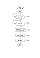
- FIG. 3 is a flowchart showing the return processing in step S207 of FIG.
- the control unit 19 determines whether or not the timer has reached a set value (step S301). When the set value is reached, the control unit 19 determines whether or not the system 22 has recovered based on the voltage / current detection output and the frequency detection output from the AC input / output unit 15, that is, the system voltage or system frequency is set. It is determined whether or not the range has been recovered (step S302).
- control unit 19 turns on the system interconnection switch 14 and turns off the gate block of the bidirectional inverter 13, that is, supplies a gate signal (step S303). Thereby, the power generation equipment 21 and the bidirectional inverter 13 are linked to the system 22.
- control unit 19 turns off the AC switch 16 (step S304), starts the operation of the MPPT function of the DC / DC converter 12 (step S305), and ends the return process.
- the AC of the system 22 is converted by the rectifying unit 17 prior to disconnection. It is rectified to a direct current and supplied to the DC / DC converter 12. Therefore, even if the bidirectional inverter 13 is subsequently disconnected, the DC load 23 can be continuously fed without being affected by the generated power of the power generation facility 21. As a result, the DC load 23 can be stably operated.
- the rectifier 17 can be easily configured by a half-wave rectifier circuit having one diode or a full-wave rectifier circuit having a diode bridge.
- the present invention is not limited to the above-described embodiment, and various modifications can be made without departing from the spirit of the invention.
- the DC / DC converter 12 can have the function of the DC input unit 11 of FIG.
- the function of the AC input / output unit 15 can be given to the bidirectional inverter 13.
- the MPPT function of the DC / DC converter 12 may be controlled to always stop the operation when the AC switch 16 is turned on.
- two grid interconnection switches 14 may be provided in series.
Landscapes
- Engineering & Computer Science (AREA)
- Power Engineering (AREA)
- Inverter Devices (AREA)
- Supply And Distribution Of Alternating Current (AREA)
Abstract
Description
発電設備から出力される直流を入力するDC/DCコンバータと、
該DC/DCコンバータの直流出力を外部に出力するための直流出力部と、
商用電源系統に接続される系統連系スイッチと、
該系統連系スイッチを介して前記商用電源系統に接続され、前記DC/DCコンバータの直流出力を交流変換して前記商用電源系統に出力するDC/AC変換を実行するインバータと、
前記系統連系スイッチの前記商用電源系統側に接続されたACスイッチと、
該ACスイッチを介して前記商用電源系統に接続され、前記商用電源系統からの交流を整流して前記DC/DCコンバータに出力する整流部と、
所定の解列条件で前記系統連系スイッチを解列する際に、該系統連系スイッチの解列の前に前記ACスイッチを並列する制御部と、
を備えることを特徴とするパワーコンディショナ。 The invention of the power conditioner according to the first aspect of achieving the above object is as follows:
A DC / DC converter for inputting a direct current output from a power generation facility;
A direct current output unit for outputting the direct current output of the DC / DC converter to the outside;
A grid interconnection switch connected to the commercial power system;
An inverter that is connected to the commercial power system via the grid interconnection switch, and that performs DC / AC conversion for converting the direct current output of the DC / DC converter into alternating current and outputting it to the commercial power system;
An AC switch connected to the commercial power system side of the grid interconnection switch;
A rectifier connected to the commercial power system via the AC switch, rectifying alternating current from the commercial power system and outputting the rectified current to the DC / DC converter;
When disconnecting the grid connection switch under a predetermined disconnection condition, a control unit that parallels the AC switch before disconnecting the grid connection switch;
A power conditioner comprising:
前記制御部は、前記ACスイッチを並列する際、前記発電設備が発電中の場合には、前記発電設備から出力される直流の電圧を前記整流部からの整流電圧に揃える、
ことを特徴とするものである。 The invention according to the second aspect is the power conditioner according to the first aspect,
The control unit aligns the DC voltage output from the power generation facility with the rectified voltage from the rectification unit when the power generation facility is generating power when the AC switches are arranged in parallel.
It is characterized by this.
前記DC/DCコンバータは、前記発電設備から出力される直流の最大電力点追従機能を有し、
前記制御部は、前記最大電力点追従機能の動作を停止させて前記発電設備から出力される直流の電圧を前記整流部からの整流電圧に揃える、
ことを特徴とするものである。 The invention according to the third aspect is the power conditioner according to the second aspect,
The DC / DC converter has a DC maximum power point tracking function output from the power generation facility,
The control unit stops the operation of the maximum power point tracking function and aligns the DC voltage output from the power generation equipment with the rectified voltage from the rectifying unit,
It is characterized by this.
前記発電設備として、太陽光パネルを含む設備に対して接続される、
ことを特徴とするものである。 The invention according to the fourth aspect is the power conditioner according to the third aspect,
As the power generation equipment, connected to equipment including solar panels,
It is characterized by this.
前記制御部は、前記商用電源系統の系統電圧または系統周波数が所定範囲から外れた場合を前記所定の解列条件として、前記系統連系スイッチの解列および前記ACスイッチの並列を制御する、
ことを特徴とするものである。 The invention according to the fifth aspect is the power conditioner according to the first aspect,
The control unit controls the disconnection of the grid interconnection switch and the parallel of the AC switch, with the predetermined disconnection condition being a case where the system voltage or system frequency of the commercial power system is out of a predetermined range.
It is characterized by this.
前記制御部は、前記所定の解列条件を検知してから、第1の時間内に前記系統連系スイッチの解列および前記ACスイッチの並列を制御する、
ことを特徴とするものである。 The invention according to a sixth aspect is the power conditioner according to the fifth aspect,
The control unit controls the disconnection of the grid interconnection switch and the parallelism of the AC switch within a first time after detecting the predetermined disconnection condition.
It is characterized by this.
前記第1の時間は2秒である、
ことを特徴とするものである。 The invention according to a seventh aspect is the power conditioner according to the fifth aspect,
The first time is 2 seconds;
It is characterized by this.
前記制御部は、前記系統連系スイッチの解列および前記ACスイッチの並列を実行した場合に、前記系統連系スイッチの解列から第2の時間経過した後に系統連系復帰処理を実行する、
ことを特徴とするものである。 The invention according to the eighth aspect is the power conditioner according to the first aspect,
The control unit performs a grid connection return process after a second time has elapsed from the disconnection of the grid connection switch when the grid switch and the AC switch are paralleled.
It is characterized by this.
前記第2の時間は10秒である、
ことを特徴とするものである。 The invention according to a ninth aspect is the power conditioner according to the eighth aspect,
The second time is 10 seconds;
It is characterized by this.
前記制御部は、前記系統連系復帰処理として、前記所定の解列条件から外れた場合に前記系統連系スイッチの並列および前記ACスイッチの解列を実行する、
ことを特徴とするものである。 The invention according to the tenth aspect is the power conditioner according to the eighth aspect,
The control unit executes parallel connection of the grid interconnection switch and disconnection of the AC switch when the predetermined disconnection condition is deviated as the grid interconnection return processing.
It is characterized by this.
前記制御部は、前記系統連系スイッチを並列する際に、前記ACスイッチの解列の前に前記系統連系スイッチの並列を実行する、
ことを特徴とするものである。 The invention according to the eleventh aspect is the power conditioner according to the tenth aspect,
The control unit, when paralleling the grid interconnection switch, executes the parallel of the grid interconnection switch before disconnecting the AC switch,
It is characterized by this.
前記DC/DCコンバータは、前記発電設備から出力される直流の最大電力点追従機能を有し、
前記制御部は、前記系統連系復帰処理の際に、前記最大電力点追従機能の動作を開始させる、
ことを特徴とするものである。 The invention according to the twelfth aspect is the power conditioner according to the eighth aspect,
The DC / DC converter has a DC maximum power point tracking function output from the power generation facility,
The control unit starts the operation of the maximum power point tracking function during the grid connection return process,
It is characterized by this.
前記インバータは、前記商用電源系統からの交流を直流変換して前記直流出力部に出力するAC/DC変換も実行可能な双方向インバータであって、
前記双方向インバータは、前記DC/AC変換および前記AC/DC変換を選択的に実行する、
ことを特徴とするものである。 The invention according to a thirteenth aspect is the power conditioner according to the first aspect,
The inverter is a bidirectional inverter that can also perform AC / DC conversion for converting AC from the commercial power supply system into DC and outputting to the DC output unit,
The bidirectional inverter selectively performs the DC / AC conversion and the AC / DC conversion.
It is characterized by this.
発電設備から出力される直流を入力するDC/DCコンバータと、
該DC/DCコンバータの直流出力を外部に出力するための直流出力部と、
商用電源系統に接続される系統連系スイッチと、
該系統連系スイッチを介して前記商用電源系統に接続され、前記DC/DCコンバータの直流出力を交流変換して前記商用電源系統に出力するDC/AC変換を実行するインバータとを備えるパワーコンディショナの制御方法であって、
前記系統連系スイッチの前記商用電源系統側に接続されたACスイッチと、
該ACスイッチを介して前記商用電源系統に接続され、前記商用電源系統からの交流を整流して前記DC/DCコンバータに出力する整流部と、
所定の解列条件で前記系統連系スイッチを解列する際に、該系統連系スイッチの解列の前に前記ACスイッチを並列する制御部と、
を備えることを特徴とするものである。 Furthermore, the invention of the control method according to the fourteenth aspect for achieving the above object is as follows:
A DC / DC converter for inputting a direct current output from a power generation facility;
A direct current output unit for outputting the direct current output of the DC / DC converter to the outside;
A grid interconnection switch connected to the commercial power system;
A power conditioner comprising: an inverter that is connected to the commercial power supply system via the grid interconnection switch, and that performs a DC / AC conversion for converting the direct current output of the DC / DC converter into an alternating current and outputting it to the commercial power supply system Control method,
An AC switch connected to the commercial power system side of the grid interconnection switch;
A rectifier connected to the commercial power system via the AC switch, rectifying alternating current from the commercial power system and outputting the rectified current to the DC / DC converter;
When disconnecting the grid connection switch under a predetermined disconnection condition, a control unit that parallels the AC switch before disconnecting the grid connection switch;
It is characterized by providing.
発電設備とパワーコンディショナとを有する発電システムであって、
前記パワーコンディショナが、
発電設備から出力される直流を入力するDC/DCコンバータと、
該DC/DCコンバータの直流出力を外部に出力するための直流出力部と、
商用電源系統に接続される系統連系スイッチと、
該系統連系スイッチを介して前記商用電源系統に接続され、前記DC/DCコンバータの直流出力を交流変換して前記商用電源系統に出力するDC/AC変換を実行するインバータと、
前記系統連系スイッチの前記商用電源系統側に接続されたACスイッチと、
該ACスイッチを介して前記商用電源系統に接続され、前記商用電源系統からの交流を整流して前記DC/DCコンバータに出力する整流部と、
所定の解列条件で前記系統連系スイッチを解列する際に、該系統連系スイッチの解列の前に前記ACスイッチを並列する制御部と、
を備えることを特徴とするものである。 Furthermore, the invention of the power generation system according to the fifteenth aspect for achieving the above object,
A power generation system having a power generation facility and a power conditioner,
The inverter is
A DC / DC converter for inputting a direct current output from a power generation facility;
A direct current output unit for outputting the direct current output of the DC / DC converter to the outside;
A grid interconnection switch connected to the commercial power system;
An inverter that is connected to the commercial power system via the grid interconnection switch, and that performs DC / AC conversion for converting the direct current output of the DC / DC converter into alternating current and outputting it to the commercial power system;
An AC switch connected to the commercial power system side of the grid interconnection switch;
A rectifier connected to the commercial power system via the AC switch, rectifying alternating current from the commercial power system and outputting the rectified current to the DC / DC converter;
When disconnecting the grid connection switch under a predetermined disconnection condition, a control unit that parallels the AC switch before disconnecting the grid connection switch;
It is characterized by providing.
11 直流入力部
12 DC/DCコンバータ
13 双方向インバータ
14 系統連系スイッチ
15 交流入出力部
16 ACスイッチ
17 整流部
18 直流出力部
19 制御部
21 発電設備
22 商用電源系統(系統)
23 直流負荷
DESCRIPTION OF
23 DC load
Claims (15)
- 発電設備から出力される直流を入力するDC/DCコンバータと、
該DC/DCコンバータの直流出力を外部に出力するための直流出力部と、
商用電源系統に接続される系統連系スイッチと、
該系統連系スイッチを介して前記商用電源系統に接続され、前記DC/DCコンバータの直流出力を交流変換して前記商用電源系統に出力するDC/AC変換を実行するインバータと、
前記系統連系スイッチの前記商用電源系統側に接続されたACスイッチと、
該ACスイッチを介して前記商用電源系統に接続され、前記商用電源系統からの交流を整流して前記DC/DCコンバータに出力する整流部と、
所定の解列条件で前記系統連系スイッチを解列する際に、該系統連系スイッチの解列の前に前記ACスイッチを並列する制御部と、
を備えることを特徴とするパワーコンディショナ。 A DC / DC converter for inputting a direct current output from a power generation facility;
A direct current output unit for outputting the direct current output of the DC / DC converter to the outside;
A grid interconnection switch connected to the commercial power system;
An inverter that is connected to the commercial power system via the grid interconnection switch, and that performs DC / AC conversion for converting the direct current output of the DC / DC converter into alternating current and outputting it to the commercial power system;
An AC switch connected to the commercial power system side of the grid interconnection switch;
A rectifier connected to the commercial power system via the AC switch, rectifying alternating current from the commercial power system and outputting the rectified current to the DC / DC converter;
When disconnecting the grid connection switch under a predetermined disconnection condition, a control unit that parallels the AC switch before disconnecting the grid connection switch;
A power conditioner comprising: - 前記制御部は、前記ACスイッチを並列する際、前記発電設備が発電中の場合には、前記発電設備から出力される直流の電圧を前記整流部からの整流電圧に揃える、
ことを特徴とする請求項1に記載のパワーコンディショナ。 The control unit aligns the DC voltage output from the power generation facility with the rectified voltage from the rectification unit when the power generation facility is generating power when the AC switches are arranged in parallel.
The power conditioner according to claim 1. - 前記DC/DCコンバータは、前記発電設備から出力される直流の最大電力点追従機能を有し、
前記制御部は、前記最大電力点追従機能の動作を停止させて前記発電設備から出力される直流の電圧を前記整流部からの整流電圧に揃える、
ことを特徴とする請求項2に記載のパワーコンディショナ。 The DC / DC converter has a DC maximum power point tracking function output from the power generation facility,
The control unit stops the operation of the maximum power point tracking function and aligns the DC voltage output from the power generation equipment with the rectified voltage from the rectifying unit,
The power conditioner according to claim 2. - 前記発電設備として、太陽光パネルを含む設備に対して接続される、
ことを特徴とする請求項3に記載のパワーコンディショナ。 As the power generation equipment, connected to equipment including solar panels,
The power conditioner according to claim 3. - 前記制御部は、前記商用電源系統の系統電圧または系統周波数が所定範囲から外れた場合を前記所定の解列条件として、前記系統連系スイッチの解列および前記ACスイッチの並列を制御する、
ことを特徴とする請求項1に記載のパワーコンディショナ。 The control unit controls the disconnection of the grid interconnection switch and the parallel of the AC switch, with the predetermined disconnection condition being a case where the system voltage or system frequency of the commercial power system is out of a predetermined range.
The power conditioner according to claim 1. - 前記制御部は、前記所定の解列条件を検知してから、第1の時間内に前記系統連系スイッチの解列および前記ACスイッチの並列を制御する、
ことを特徴とする請求項5に記載のパワーコンディショナ。 The control unit controls the disconnection of the grid interconnection switch and the parallelism of the AC switch within a first time after detecting the predetermined disconnection condition.
The power conditioner according to claim 5. - 前記第1の時間は2秒である、
ことを特徴とする請求項5に記載のパワーコンディショナ。 The first time is 2 seconds;
The power conditioner according to claim 5. - 前記制御部は、前記系統連系スイッチの解列および前記ACスイッチの並列を実行した場合に、前記系統連系スイッチの解列から第2の時間経過した後に系統連系復帰処理を実行する、
ことを特徴とする請求項1に記載のパワーコンディショナ。 The control unit performs a grid connection return process after a second time has elapsed from the disconnection of the grid connection switch when the grid switch and the AC switch are paralleled.
The power conditioner according to claim 1. - 前記第2の時間は10秒である、
ことを特徴とする請求項8に記載のパワーコンディショナ。 The second time is 10 seconds;
The power conditioner according to claim 8. - 前記制御部は、前記系統連系復帰処理として、前記所定の解列条件から外れた場合に前記系統連系スイッチの並列および前記ACスイッチの解列を実行する、
ことを特徴とする請求項8に記載のパワーコンディショナ。 The control unit executes parallel connection of the grid interconnection switch and disconnection of the AC switch when the predetermined disconnection condition is deviated as the grid interconnection return processing.
The power conditioner according to claim 8. - 前記制御部は、前記系統連系スイッチを並列する際に、前記ACスイッチの解列の前に前記系統連系スイッチの並列を実行する、
ことを特徴とする請求項10に記載のパワーコンディショナ。 The control unit, when paralleling the grid interconnection switch, executes the parallel of the grid interconnection switch before disconnecting the AC switch,
The power conditioner according to claim 10. - 前記DC/DCコンバータは、前記発電設備から出力される直流の最大電力点追従機能を有し、
前記制御部は、前記系統連系復帰処理の際に、前記最大電力点追従機能の動作を開始させる、
ことを特徴とする請求項8に記載のパワーコンディショナ。 The DC / DC converter has a DC maximum power point tracking function output from the power generation facility,
The control unit starts the operation of the maximum power point tracking function during the grid connection return process,
The power conditioner according to claim 8. - 前記インバータは、前記商用電源系統からの交流を直流変換して前記直流出力部に出力するAC/DC変換も実行可能な双方向インバータであって、
前記双方向インバータは、前記DC/AC変換および前記AC/DC変換を選択的に実行する、
ことを特徴とする請求項1に記載のパワーコンディショナ。 The inverter is a bidirectional inverter that can also perform AC / DC conversion for converting AC from the commercial power supply system into DC and outputting to the DC output unit,
The bidirectional inverter selectively performs the DC / AC conversion and the AC / DC conversion.
The power conditioner according to claim 1. - 発電設備から出力される直流を入力するDC/DCコンバータと、
該DC/DCコンバータの直流出力を外部に出力するための直流出力部と、
商用電源系統に接続される系統連系スイッチと、
該系統連系スイッチを介して前記商用電源系統に接続され、前記DC/DCコンバータの直流出力を交流変換して前記商用電源系統に出力するDC/AC変換を実行するインバータとを備えるパワーコンディショナの制御方法であって、
前記系統連系スイッチの前記商用電源系統側に接続されたACスイッチと、
該ACスイッチを介して前記商用電源系統に接続され、前記商用電源系統からの交流を整流して前記DC/DCコンバータに出力する整流部と、
所定の解列条件で前記系統連系スイッチを解列する際に、該系統連系スイッチの解列の前に前記ACスイッチを並列する制御部と、
を備えることを特徴とする制御方法。 A DC / DC converter for inputting a direct current output from a power generation facility;
A direct current output unit for outputting the direct current output of the DC / DC converter to the outside;
A grid interconnection switch connected to the commercial power system;
A power conditioner comprising: an inverter that is connected to the commercial power supply system via the grid interconnection switch, and that performs a DC / AC conversion for converting the direct current output of the DC / DC converter into an alternating current and outputting it to the commercial power supply system Control method,
An AC switch connected to the commercial power system side of the grid interconnection switch;
A rectifier connected to the commercial power system via the AC switch, rectifying alternating current from the commercial power system and outputting the rectified current to the DC / DC converter;
When disconnecting the grid connection switch under a predetermined disconnection condition, a control unit that parallels the AC switch before disconnecting the grid connection switch;
A control method comprising: - 発電設備とパワーコンディショナとを有する発電システムであって、
前記パワーコンディショナが、
発電設備から出力される直流を入力するDC/DCコンバータと、
該DC/DCコンバータの直流出力を外部に出力するための直流出力部と、
商用電源系統に接続される系統連系スイッチと、
該系統連系スイッチを介して前記商用電源系統に接続され、前記DC/DCコンバータの直流出力を交流変換して前記商用電源系統に出力するDC/AC変換を実行するインバータと、
前記系統連系スイッチの前記商用電源系統側に接続されたACスイッチと、
該ACスイッチを介して前記商用電源系統に接続され、前記商用電源系統からの交流を整流して前記DC/DCコンバータに出力する整流部と、
所定の解列条件で前記系統連系スイッチを解列する際に、該系統連系スイッチの解列の前に前記ACスイッチを並列する制御部と、
を備えることを特徴とする発電システム。
A power generation system having a power generation facility and a power conditioner,
The inverter is
A DC / DC converter for inputting a direct current output from a power generation facility;
A direct current output unit for outputting the direct current output of the DC / DC converter to the outside;
A grid interconnection switch connected to the commercial power system;
An inverter that is connected to the commercial power system via the grid interconnection switch, and that performs DC / AC conversion for converting the direct current output of the DC / DC converter into alternating current and outputting it to the commercial power system;
An AC switch connected to the commercial power system side of the grid interconnection switch;
A rectifier connected to the commercial power system via the AC switch, rectifying alternating current from the commercial power system and outputting the rectified current to the DC / DC converter;
When disconnecting the grid connection switch under a predetermined disconnection condition, a control unit that parallels the AC switch before disconnecting the grid connection switch;
A power generation system comprising:
Priority Applications (4)
| Application Number | Priority Date | Filing Date | Title |
|---|---|---|---|
| EP20120802907 EP2725676A4 (en) | 2011-06-22 | 2012-06-22 | Power conditioner, control method and power generation system |
| US14/128,503 US20140132073A1 (en) | 2011-06-22 | 2012-06-22 | Power conditioner, control method and power generation system |
| JP2013521478A JP5646751B2 (en) | 2011-06-22 | 2012-06-22 | Power conditioner, control method, and power generation system |
| CN201280030937.2A CN103688437B (en) | 2011-06-22 | 2012-06-22 | Power governor, control method and electricity generation system |
Applications Claiming Priority (2)
| Application Number | Priority Date | Filing Date | Title |
|---|---|---|---|
| JP2011-138793 | 2011-06-22 | ||
| JP2011138793 | 2011-06-22 |
Publications (1)
| Publication Number | Publication Date |
|---|---|
| WO2012176477A1 true WO2012176477A1 (en) | 2012-12-27 |
Family
ID=47422331
Family Applications (1)
| Application Number | Title | Priority Date | Filing Date |
|---|---|---|---|
| PCT/JP2012/004082 WO2012176477A1 (en) | 2011-06-22 | 2012-06-22 | Power conditioner, control method and power generation system |
Country Status (5)
| Country | Link |
|---|---|
| US (1) | US20140132073A1 (en) |
| EP (1) | EP2725676A4 (en) |
| JP (1) | JP5646751B2 (en) |
| CN (1) | CN103688437B (en) |
| WO (1) | WO2012176477A1 (en) |
Cited By (4)
| Publication number | Priority date | Publication date | Assignee | Title |
|---|---|---|---|---|
| CN103837765A (en) * | 2013-09-17 | 2014-06-04 | 株洲南车时代电气股份有限公司 | Energy-regeneration type converter power test system and method |
| JP2015154691A (en) * | 2014-02-19 | 2015-08-24 | 田淵電機株式会社 | Power conversion device |
| WO2018142579A1 (en) * | 2017-02-03 | 2018-08-09 | 東芝三菱電機産業システム株式会社 | Uninterruptible power supply device |
| JP2018186700A (en) * | 2017-05-29 | 2018-11-22 | 京セラ株式会社 | Management system, management method, control unit, and storage battery device |
Families Citing this family (12)
| Publication number | Priority date | Publication date | Assignee | Title |
|---|---|---|---|---|
| US8971057B2 (en) * | 2009-03-25 | 2015-03-03 | Stem, Inc | Bidirectional energy converter with controllable filter stage |
| JP5646752B2 (en) * | 2011-06-28 | 2014-12-24 | 京セラ株式会社 | Grid-connected inverter device and control method thereof |
| DE102011083741A1 (en) * | 2011-09-29 | 2013-04-04 | Siemens Ag | circuitry |
| JP5968719B2 (en) * | 2012-08-06 | 2016-08-10 | 京セラ株式会社 | Management system, management method, control device, and storage battery device |
| CN104375039B (en) * | 2014-11-21 | 2017-05-10 | 华北电力大学(保定) | Testing system for isolation type direct-current transformer |
| US10797514B2 (en) * | 2016-02-25 | 2020-10-06 | Bloom Energy Corporation | Fuel cell system for information technology loads |
| US10998746B2 (en) * | 2017-04-03 | 2021-05-04 | Smart Charging Technologies Llc | Direct current uninterruptible power supply with AC power supply and related methods |
| US10525833B2 (en) * | 2017-08-14 | 2020-01-07 | Hamilton Sundstrand Corporation | Tactical vehicle to grid electric power architecture |
| DE102017217729B4 (en) | 2017-10-05 | 2020-01-23 | Audi Ag | Energy supply device for providing electrical energy for at least one terminal and method for operating an energy supply device |
| CN109818569B (en) * | 2017-11-18 | 2021-06-08 | 丰郅(上海)新能源科技有限公司 | Parallel type turn-off system for photovoltaic module and method for restarting after turn-off |
| WO2021000253A1 (en) * | 2019-07-02 | 2021-01-07 | Marich Holdings The Netherlands B.V. | Photovoltaic system and control method thereof |
| BE1028004B1 (en) * | 2019-12-30 | 2021-08-24 | Futech Bvba | DC source in electrical installation |
Citations (4)
| Publication number | Priority date | Publication date | Assignee | Title |
|---|---|---|---|---|
| JP2000083330A (en) * | 1998-09-03 | 2000-03-21 | Nissin Electric Co Ltd | Distributed power supply installation |
| JP2002135982A (en) * | 2000-10-18 | 2002-05-10 | Mitsubishi Electric Corp | Uninterruptible power supply switchable to independent operation |
| JP2003189477A (en) | 2001-12-14 | 2003-07-04 | Daikin Ind Ltd | Power controller |
| JP2010041886A (en) * | 2008-08-07 | 2010-02-18 | Panasonic Electric Works Co Ltd | Power distribution system |
Family Cites Families (9)
| Publication number | Priority date | Publication date | Assignee | Title |
|---|---|---|---|---|
| US6737762B2 (en) * | 2001-10-26 | 2004-05-18 | Onan Corporation | Generator with DC boost for uninterruptible power supply system or for enhanced load pickup |
| US6940735B2 (en) * | 2003-11-14 | 2005-09-06 | Ballard Power Systems Corporation | Power converter system |
| US7193872B2 (en) * | 2005-01-28 | 2007-03-20 | Kasemsan Siri | Solar array inverter with maximum power tracking |
| JP5124114B2 (en) * | 2006-08-28 | 2013-01-23 | シャープ株式会社 | Power conditioner with power storage function |
| TWI384720B (en) * | 2008-07-17 | 2013-02-01 | Atomic Energy Council | Dc power system for household appliances |
| DE102009040090A1 (en) * | 2009-09-04 | 2011-03-10 | Voltwerk Electronics Gmbh | Island unit for a power grid with a control unit for controlling an energy flow between the power generation unit, the energy storage unit, the load unit and / or the power grid |
| EP2325970A3 (en) * | 2009-11-19 | 2015-01-21 | Samsung SDI Co., Ltd. | Energy management system and grid-connected energy storage system including the energy management system |
| KR101074785B1 (en) * | 2010-05-31 | 2011-10-19 | 삼성에스디아이 주식회사 | A battery management system and control method thereof, and energy storage system including the battery management system |
| CN201829966U (en) * | 2010-08-03 | 2011-05-11 | 上海兆能电力电子技术有限公司 | Photovoltaic wind-driven grid-connected generating system with discontinuous power supply function |
-
2012
- 2012-06-22 US US14/128,503 patent/US20140132073A1/en not_active Abandoned
- 2012-06-22 JP JP2013521478A patent/JP5646751B2/en not_active Expired - Fee Related
- 2012-06-22 EP EP20120802907 patent/EP2725676A4/en not_active Withdrawn
- 2012-06-22 CN CN201280030937.2A patent/CN103688437B/en not_active Expired - Fee Related
- 2012-06-22 WO PCT/JP2012/004082 patent/WO2012176477A1/en active Application Filing
Patent Citations (4)
| Publication number | Priority date | Publication date | Assignee | Title |
|---|---|---|---|---|
| JP2000083330A (en) * | 1998-09-03 | 2000-03-21 | Nissin Electric Co Ltd | Distributed power supply installation |
| JP2002135982A (en) * | 2000-10-18 | 2002-05-10 | Mitsubishi Electric Corp | Uninterruptible power supply switchable to independent operation |
| JP2003189477A (en) | 2001-12-14 | 2003-07-04 | Daikin Ind Ltd | Power controller |
| JP2010041886A (en) * | 2008-08-07 | 2010-02-18 | Panasonic Electric Works Co Ltd | Power distribution system |
Non-Patent Citations (2)
| Title |
|---|
| "Grid Interconnection Technical Requirements Guidelines for Guaranteeing Electric Power Quality", 1 October 2004, AGENCY FOR NATURAL RESOURCES AND ENERGY |
| See also references of EP2725676A4 |
Cited By (5)
| Publication number | Priority date | Publication date | Assignee | Title |
|---|---|---|---|---|
| CN103837765A (en) * | 2013-09-17 | 2014-06-04 | 株洲南车时代电气股份有限公司 | Energy-regeneration type converter power test system and method |
| CN103837765B (en) * | 2013-09-17 | 2016-09-14 | 株洲南车时代电气股份有限公司 | Type current transformer power test system and method thereof can be presented |
| JP2015154691A (en) * | 2014-02-19 | 2015-08-24 | 田淵電機株式会社 | Power conversion device |
| WO2018142579A1 (en) * | 2017-02-03 | 2018-08-09 | 東芝三菱電機産業システム株式会社 | Uninterruptible power supply device |
| JP2018186700A (en) * | 2017-05-29 | 2018-11-22 | 京セラ株式会社 | Management system, management method, control unit, and storage battery device |
Also Published As
| Publication number | Publication date |
|---|---|
| JP5646751B2 (en) | 2014-12-24 |
| CN103688437B (en) | 2016-03-30 |
| CN103688437A (en) | 2014-03-26 |
| JPWO2012176477A1 (en) | 2015-02-23 |
| EP2725676A4 (en) | 2015-03-18 |
| EP2725676A1 (en) | 2014-04-30 |
| US20140132073A1 (en) | 2014-05-15 |
Similar Documents
| Publication | Publication Date | Title |
|---|---|---|
| JP5646751B2 (en) | Power conditioner, control method, and power generation system | |
| JP5344759B2 (en) | Power distribution system | |
| JP5311153B2 (en) | Power control apparatus and power control method | |
| KR101830666B1 (en) | Power conversion apparatus | |
| WO2013001820A1 (en) | System connection inverter device and control method therefor | |
| US20160172861A1 (en) | Power conversion apparatus, method for power management, and power conversion system | |
| JP6248720B2 (en) | Power supply device and control method thereof | |
| JP6599700B2 (en) | Grid interconnection device | |
| KR101477395B1 (en) | Fuel cell power supply system | |
| JP2008283788A (en) | Control power supply circuit of uninterruptive power supply device | |
| JP6145777B2 (en) | Power converter | |
| US20150115713A1 (en) | Power supply apparatus | |
| JP5680525B2 (en) | Power storage system, power storage control device, and power control method | |
| JP2016001981A (en) | Dc power transmission system | |
| JP6415259B2 (en) | Power conditioner and its control device | |
| JPWO2014038020A1 (en) | Station building power supply | |
| JP6000144B2 (en) | Distributed power system | |
| JP2012196024A (en) | Electric power controller and electric power control method | |
| JP2018033226A (en) | Photovoltaic power generation system | |
| JP6415260B2 (en) | Power conditioner, its control device and power system | |
| JP5790084B2 (en) | Power generation system | |
| JP7363858B2 (en) | power conditioner | |
| JP6089836B2 (en) | Grid connection system for fuel cells | |
| JP2016096613A (en) | Power supply device and storage system | |
| JP2016096646A (en) | Power supply system |
Legal Events
| Date | Code | Title | Description |
|---|---|---|---|
| WWE | Wipo information: entry into national phase |
Ref document number: 201280030937.2 Country of ref document: CN |
|
| 121 | Ep: the epo has been informed by wipo that ep was designated in this application |
Ref document number: 12802907 Country of ref document: EP Kind code of ref document: A1 |
|
| ENP | Entry into the national phase |
Ref document number: 2013521478 Country of ref document: JP Kind code of ref document: A |
|
| REEP | Request for entry into the european phase |
Ref document number: 2012802907 Country of ref document: EP |
|
| WWE | Wipo information: entry into national phase |
Ref document number: 14128503 Country of ref document: US |
|
| NENP | Non-entry into the national phase |
Ref country code: DE |