WO2012173352A9 - Polymer electrolyte membrane for fuel cell, and membrane electrode conjugate and fuel cell comprising same - Google Patents
Polymer electrolyte membrane for fuel cell, and membrane electrode conjugate and fuel cell comprising same Download PDFInfo
- Publication number
- WO2012173352A9 WO2012173352A9 PCT/KR2012/004416 KR2012004416W WO2012173352A9 WO 2012173352 A9 WO2012173352 A9 WO 2012173352A9 KR 2012004416 W KR2012004416 W KR 2012004416W WO 2012173352 A9 WO2012173352 A9 WO 2012173352A9
- Authority
- WO
- WIPO (PCT)
- Prior art keywords
- fuel cell
- electrolyte membrane
- polymer electrolyte
- cellulose
- group
- Prior art date
Links
Images


Classifications
-
- H—ELECTRICITY
- H01—ELECTRIC ELEMENTS
- H01M—PROCESSES OR MEANS, e.g. BATTERIES, FOR THE DIRECT CONVERSION OF CHEMICAL ENERGY INTO ELECTRICAL ENERGY
- H01M8/00—Fuel cells; Manufacture thereof
- H01M8/10—Fuel cells with solid electrolytes
- H01M8/1016—Fuel cells with solid electrolytes characterised by the electrolyte material
- H01M8/1018—Polymeric electrolyte materials
- H01M8/1041—Polymer electrolyte composites, mixtures or blends
- H01M8/1046—Mixtures of at least one polymer and at least one additive
- H01M8/1051—Non-ion-conducting additives, e.g. stabilisers, SiO2 or ZrO2
-
- D—TEXTILES; PAPER
- D01—NATURAL OR MAN-MADE THREADS OR FIBRES; SPINNING
- D01D—MECHANICAL METHODS OR APPARATUS IN THE MANUFACTURE OF ARTIFICIAL FILAMENTS, THREADS, FIBRES, BRISTLES OR RIBBONS
- D01D5/00—Formation of filaments, threads, or the like
- D01D5/40—Formation of filaments, threads, or the like by applying a shearing force to a dispersion or solution of filament formable polymers, e.g. by stirring
-
- H—ELECTRICITY
- H01—ELECTRIC ELEMENTS
- H01M—PROCESSES OR MEANS, e.g. BATTERIES, FOR THE DIRECT CONVERSION OF CHEMICAL ENERGY INTO ELECTRICAL ENERGY
- H01M8/00—Fuel cells; Manufacture thereof
- H01M8/02—Details
-
- C—CHEMISTRY; METALLURGY
- C08—ORGANIC MACROMOLECULAR COMPOUNDS; THEIR PREPARATION OR CHEMICAL WORKING-UP; COMPOSITIONS BASED THEREON
- C08J—WORKING-UP; GENERAL PROCESSES OF COMPOUNDING; AFTER-TREATMENT NOT COVERED BY SUBCLASSES C08B, C08C, C08F, C08G or C08H
- C08J5/00—Manufacture of articles or shaped materials containing macromolecular substances
- C08J5/20—Manufacture of shaped structures of ion-exchange resins
- C08J5/22—Films, membranes or diaphragms
-
- C—CHEMISTRY; METALLURGY
- C08—ORGANIC MACROMOLECULAR COMPOUNDS; THEIR PREPARATION OR CHEMICAL WORKING-UP; COMPOSITIONS BASED THEREON
- C08K—Use of inorganic or non-macromolecular organic substances as compounding ingredients
- C08K7/00—Use of ingredients characterised by shape
- C08K7/02—Fibres or whiskers
-
- C—CHEMISTRY; METALLURGY
- C08—ORGANIC MACROMOLECULAR COMPOUNDS; THEIR PREPARATION OR CHEMICAL WORKING-UP; COMPOSITIONS BASED THEREON
- C08L—COMPOSITIONS OF MACROMOLECULAR COMPOUNDS
- C08L27/00—Compositions of homopolymers or copolymers of compounds having one or more unsaturated aliphatic radicals, each having only one carbon-to-carbon double bond, and at least one being terminated by a halogen; Compositions of derivatives of such polymers
- C08L27/02—Compositions of homopolymers or copolymers of compounds having one or more unsaturated aliphatic radicals, each having only one carbon-to-carbon double bond, and at least one being terminated by a halogen; Compositions of derivatives of such polymers not modified by chemical after-treatment
- C08L27/12—Compositions of homopolymers or copolymers of compounds having one or more unsaturated aliphatic radicals, each having only one carbon-to-carbon double bond, and at least one being terminated by a halogen; Compositions of derivatives of such polymers not modified by chemical after-treatment containing fluorine atoms
-
- D—TEXTILES; PAPER
- D01—NATURAL OR MAN-MADE THREADS OR FIBRES; SPINNING
- D01F—CHEMICAL FEATURES IN THE MANUFACTURE OF ARTIFICIAL FILAMENTS, THREADS, FIBRES, BRISTLES OR RIBBONS; APPARATUS SPECIALLY ADAPTED FOR THE MANUFACTURE OF CARBON FILAMENTS
- D01F2/00—Monocomponent artificial filaments or the like of cellulose or cellulose derivatives; Manufacture thereof
- D01F2/24—Monocomponent artificial filaments or the like of cellulose or cellulose derivatives; Manufacture thereof from cellulose derivatives
- D01F2/28—Monocomponent artificial filaments or the like of cellulose or cellulose derivatives; Manufacture thereof from cellulose derivatives from organic cellulose esters or ethers, e.g. cellulose acetate
-
- H—ELECTRICITY
- H01—ELECTRIC ELEMENTS
- H01M—PROCESSES OR MEANS, e.g. BATTERIES, FOR THE DIRECT CONVERSION OF CHEMICAL ENERGY INTO ELECTRICAL ENERGY
- H01M8/00—Fuel cells; Manufacture thereof
- H01M8/10—Fuel cells with solid electrolytes
- H01M8/1016—Fuel cells with solid electrolytes characterised by the electrolyte material
- H01M8/1018—Polymeric electrolyte materials
- H01M8/102—Polymeric electrolyte materials characterised by the chemical structure of the main chain of the ion-conducting polymer
- H01M8/1023—Polymeric electrolyte materials characterised by the chemical structure of the main chain of the ion-conducting polymer having only carbon, e.g. polyarylenes, polystyrenes or polybutadiene-styrenes
-
- H—ELECTRICITY
- H01—ELECTRIC ELEMENTS
- H01M—PROCESSES OR MEANS, e.g. BATTERIES, FOR THE DIRECT CONVERSION OF CHEMICAL ENERGY INTO ELECTRICAL ENERGY
- H01M8/00—Fuel cells; Manufacture thereof
- H01M8/10—Fuel cells with solid electrolytes
- H01M8/1016—Fuel cells with solid electrolytes characterised by the electrolyte material
- H01M8/1018—Polymeric electrolyte materials
- H01M8/1039—Polymeric electrolyte materials halogenated, e.g. sulfonated polyvinylidene fluorides
-
- H—ELECTRICITY
- H01—ELECTRIC ELEMENTS
- H01M—PROCESSES OR MEANS, e.g. BATTERIES, FOR THE DIRECT CONVERSION OF CHEMICAL ENERGY INTO ELECTRICAL ENERGY
- H01M8/00—Fuel cells; Manufacture thereof
- H01M8/10—Fuel cells with solid electrolytes
- H01M8/1016—Fuel cells with solid electrolytes characterised by the electrolyte material
- H01M8/1018—Polymeric electrolyte materials
- H01M8/1041—Polymer electrolyte composites, mixtures or blends
- H01M8/1053—Polymer electrolyte composites, mixtures or blends consisting of layers of polymers with at least one layer being ionically conductive
-
- H—ELECTRICITY
- H01—ELECTRIC ELEMENTS
- H01M—PROCESSES OR MEANS, e.g. BATTERIES, FOR THE DIRECT CONVERSION OF CHEMICAL ENERGY INTO ELECTRICAL ENERGY
- H01M8/00—Fuel cells; Manufacture thereof
- H01M8/10—Fuel cells with solid electrolytes
- H01M8/1016—Fuel cells with solid electrolytes characterised by the electrolyte material
- H01M8/1018—Polymeric electrolyte materials
- H01M8/1058—Polymeric electrolyte materials characterised by a porous support having no ion-conducting properties
-
- H—ELECTRICITY
- H01—ELECTRIC ELEMENTS
- H01M—PROCESSES OR MEANS, e.g. BATTERIES, FOR THE DIRECT CONVERSION OF CHEMICAL ENERGY INTO ELECTRICAL ENERGY
- H01M8/00—Fuel cells; Manufacture thereof
- H01M8/10—Fuel cells with solid electrolytes
- H01M2008/1095—Fuel cells with polymeric electrolytes
-
- Y—GENERAL TAGGING OF NEW TECHNOLOGICAL DEVELOPMENTS; GENERAL TAGGING OF CROSS-SECTIONAL TECHNOLOGIES SPANNING OVER SEVERAL SECTIONS OF THE IPC; TECHNICAL SUBJECTS COVERED BY FORMER USPC CROSS-REFERENCE ART COLLECTIONS [XRACs] AND DIGESTS
- Y02—TECHNOLOGIES OR APPLICATIONS FOR MITIGATION OR ADAPTATION AGAINST CLIMATE CHANGE
- Y02E—REDUCTION OF GREENHOUSE GAS [GHG] EMISSIONS, RELATED TO ENERGY GENERATION, TRANSMISSION OR DISTRIBUTION
- Y02E60/00—Enabling technologies; Technologies with a potential or indirect contribution to GHG emissions mitigation
- Y02E60/30—Hydrogen technology
- Y02E60/50—Fuel cells
Definitions
- the present invention relates to a polymer electrolyte membrane for a fuel cell for improving the mechanical properties of the electrolyte membrane, and more particularly to a polymer electrolyte membrane for a fuel cell by improving the mechanical properties of the polymer electrolyte membrane for fuel cells by including fibrous nanoparticles having a hydrophilic group, It relates to a membrane electrode assembly and a fuel cell comprising such a polymer electrolyte membrane.
- the fuel cell is particularly attracting attention due to its advantages such as high efficiency, no pollutants such as NO x and SO x , and abundant fuel used.
- a fuel cell is a power generation system that converts chemical reaction energy of a fuel and an oxidant into electrical energy, and hydrocarbons such as hydrogen, methanol, butane, and the like are typically used as fuel.
- the most basic unit for generating electricity is a membrane-electrode assembly (MEA), which consists of an anode and a cathode electrode formed on both sides of the polymer electrolyte membrane and the polymer electrolyte membrane.
- MEA membrane-electrode assembly
- the polymer electrolyte membrane is accompanied by a change in film thickness and volume of 15 to 30% depending on temperature and degree of hydration, and in particular, at a volume of at least 200% by 3 to 50% by weight of methanol fuel. Change occurs. Accordingly, depending on the fuel cell operating conditions, the electrolyte membrane repeats swelling and contraction. Due to the volume change, the polymer chain is entangled in the polymer electrolyte membrane, and mechanical strength is reduced, and micropores or cracks are generated. Hydrogen or methanol crossovers are generated through such micropores or cracks, which is a major cause of deterioration of fuel cell durability.
- the polymer electrolyte membrane mainly uses a fluorine-based cation exchange resin having excellent conductivity, mechanical properties and chemical resistance.
- a perfluorosulfonic acid resin film made of a perfluorosulfonic acid resin (trade name: Nafion) is mainly used.
- the perfluorosulfonic acid resin has a tensile strength in the range of 26 to 34 MPa when wet at room temperature and 32 to 43 MPa at 50% relative humidity. Tensile strength of the perfluorosulfonic acid resin may be largely unreasonable under normal fuel cell operating conditions, but fuel cells used in vehicles are required to operate without difficulty in more extreme conditions, and thus have higher mechanical properties. To be required.
- the present invention aims to solve the problems of the prior art as described above and the technical problems that have been requested from the past.
- the first object of the present invention is to provide a polymer electrolyte membrane that significantly improves the mechanical properties of the conventional polymer electrolyte membrane for fuel cells by including fibrous nanoparticles having a hydrophilic group.
- a second object of the present invention is to provide a membrane electrode assembly comprising the polymer electrolyte membrane for fuel cells.
- the present invention provides a polymer electrolyte membrane for a fuel cell comprising a fluorine-based cation exchange resin having a hydrogen ion conductivity and fibrous nanoparticles having a hydrophilic group.
- the fluorine-based cation exchange resin having a hydrogen ion conductivity includes fibrous nanoparticles having a hydrophilic group
- the stress due to volume change by interlocking the fibrous nanoparticles having a hydrophilic group during swelling and shrinkage of the fluorine-based cation exchange resin Due to the presence of the hydrophilic group can reduce the degree of shrinkage due to moisture loss even in low humidification state, it is possible to improve the tensile strength in the situation exposed to moisture.
- the fibrous nanoparticles may have a small particle size, a large surface area, and may be evenly dispersed in a fluorine-based cation exchange resin having hydrogen ion conductivity due to hydrophilic groups, thereby greatly contributing to the improvement of mechanical properties of the prepared polymer electrolyte membrane.
- the process becomes very simple as compared with the case of using a porous substrate or the like. Therefore, when manufacturing a fuel cell using the polymer electrolyte membrane as described above, it is possible to produce a fuel cell having excellent long-term durability.
- the mixing ratio of the fluorine-based cation exchange resin having a hydrogen ion conductivity and the fibrous nanoparticles having a hydrophilic group may be in the range of 99.9: 0.1 to 95: 5 by weight.
- the fibrous nanoparticles having a hydrophilic group When the content of the fibrous nanoparticles having a hydrophilic group is too small, it is difficult to improve the mechanical properties to a desired level. On the contrary, when the content of the fibrous nanoparticles is too large, the fibrous nanoparticles partially aggregate to form a path for crossover of fuel. It is not desirable because it can.
- the fibrous nanoparticles having a hydrophilic group may be contained in an amount of 0.1 to 3% by weight based on the total amount of the electrolyte membrane.
- the fibrous nanoparticles having the hydrophilic group may be prepared by decomposing a material that is a raw material of the fibrous nanoparticles using a microfluidizer, but the method is not particularly limited.
- Microfluidizer is a machine designed to make a fine tube separate into two flow paths and then merge into one flow path.
- the dispersion is injected into this machine, the dispersion is separated by two flow paths. They are moved and collide with each other at the point where the flow paths merge into one and are broken down into particles having a fine size.
- the moving dispersion moves at high speeds of hundreds of meters per second under high pressure, at which time the speed determines the decomposing force of the material.
- the diameter of the fibrous nanoparticles having a hydrophilic group is 1 to 200 nm, specifically 10 to 200 nm, the length may be 1 to 20 ⁇ m.
- the fibrous nanoparticles having the hydrophilic group have a particle size of the nano level, it can be more uniformly dispersed in the cation exchange resin, it is possible to improve the durability even in a small amount.
- the diameter of the fibrous nanoparticles having hydrophilic groups is too small, it is difficult to contribute to the improvement of mechanical strength.
- the diameter of the fibrous nanoparticles is too large, it may be difficult to expect the effect of improving the bonding strength by increasing the surface area characteristic of the fibrous nanoparticles.
- the length of the fibrous nanoparticles having a hydrophilic group is short, it is difficult to have a fibrous form.
- the length of the fibrous nanoparticles is too large, dispersibility in the cation exchange resin is lowered, which is not preferable.
- the aspect ratio of the fibrous nanoparticles having a hydrophilic group may range from 1: 5 to 1: 2,000.
- the aspect ratio When the aspect ratio is too small, it is difficult to have a fibrous form, and consequently, it is difficult to contribute to the improvement of mechanical strength. On the contrary, when the aspect ratio is too large, the dispersibility is lowered, and agglomeration occurs partially in the cation exchange resin. It is undesirable because it can act as a passage.
- the fibrous nanoparticle having the hydrophilic group is not particularly limited as long as the fibrous nanoparticles have the above properties, but examples thereof include cellulose-based nanofibers.
- Cellulose-based nanofibers are composed of a crystallization region and an amorphous region, the crystallization region increases the elasticity and tensile strength of the material, the amorphous region increases the absorption of water or improves the flexibility of the material Do it.
- the cellulose-based nanofibers have a hydroxyl group (—OH) as a hydrophilic group.
- the hydroxy group of the cellulose-based nanofiber may be present in the range of 5 to 90% of the total hydroxyl group site.
- More specific content of hydroxy groups can be 10 to 80%, in particular 20 to 70%.
- the cellulose-based nanofibers include, for example, cellulose unsubstituted cellulose nanofibers, cellulose partially hydroxy substituted cellulose such as cellulose ester nanofibers, cellulose ether nanofibers, and the like. It may be roughly classified into nanofibers, which may be used alone or in a mixture of two or more.
- cellulose unsubstituted cellulose nanofibers include cellulose unsubstituted cellulose nanofibers; Cellulose nanofibers substituted with acetyl groups or derivatives thereof; Sulfuric acid cellulose nanofibers; Phosphate cellulose nanofibers; Cellulose nanofibers substituted with C 1 -C 10 alkyl groups or derivatives thereof such as methyl cellulose nanofibers, ethyl cellulose nanofibers, carboxymethyl cellulose nanofibers, hydroxyethyl cellulose nanofibers, and the like.
- one or more selected from the group consisting of cellulose nanofibers substituted with a C 2 -C 6 alkyl group or a derivative thereof but is not limited thereto.
- cellulose nanofibers substituted with a more water-soluble low C 2 -C 10 alkyl group or derivatives thereof cellulose nanofibers substituted with an acetyl group or derivatives thereof, and the like.
- the molecular weight range of the cellulose may be, for example, 30,000 to 3,000,000, but may be beyond the exemplary range due to various factors such as the aspect ratio of the fibrous nanoparticles, the type of the substituent, and the degree of substitution. to be.
- the fluorine-based cation exchange resin may be composed of a main chain which is a continuous chain of molecules formed by covalent bonds of atoms, and a side chain extending from the main chain into branches.
- the fluorine-based cation exchange resin having the hydrogen ion conductivity is, for example, a polymer having at least one cation exchange group selected from the group consisting of sulfonic acid groups, carboxylic acid groups, phosphoric acid groups, phosphonic acid groups and derivatives thereof in the side chain. Can be.
- the fluorine-based cation exchange resin having a hydrogen ion conductivity may be a perfluorosulfonic acid resin.
- the fluorine-based cation exchange resin having a hydrogen ion conductivity of the present invention comprises a fluorine-based in the range of 30 to 99% by weight, more specifically 50 to 80% by weight based on the total weight of the fluorine-based cation exchange resin having a hydrogen ion conductivity. can do.
- the fuel cell polymer electrolyte membrane may further include a cation exchange resin membrane having two or more hydrogen ion conductivity stacked opposite to each other with the fuel cell polymer electrolyte membrane interposed therebetween.
- a method of coating and thermally pressing corresponding films, respectively may be used, and a known film lamination method may be used without limitation.
- the present invention also provides a fuel cell membrane electrode assembly in which the fuel cell polymer electrolyte membrane is positioned between an anode electrode and a cathode electrode which face each other.
- the membrane electrode assembly for fuel cell has an advantage in that the mechanical strength of the polymer electrolyte membrane inside the fuel cell during operation is greatly improved and thus the durability is excellent.
- the present invention includes the fuel cell membrane electrode assembly and at least one separator plate,
- At least one electricity generating unit for generating electricity through an electrochemical reaction between the fuel and the oxidant
- a fuel supply unit supplying fuel to the electricity generation unit
- An oxidant supply unit for supplying an oxidant to the electricity generating unit
- It provides a fuel cell comprising a.
- 1 is a schematic diagram for explaining the principle of electricity generation of a fuel cell
- FIG. 2 is a schematic diagram schematically showing a polymer electrolyte membrane according to one embodiment of the present invention
- FIG. 3 is a schematic diagram schematically showing the structure of a membrane electrode assembly for a fuel cell according to one embodiment of the present invention
- FIG. 4 is a schematic diagram schematically showing the structure of a fuel cell according to one embodiment of the present invention.
- 5A and 5B are transmission electron microscope (TEM) photographs showing the shapes of cellulose before and after microfluidizer treatment according to one embodiment of the present invention, respectively;
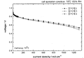
- 6 and 7 are graphs showing performance test results under 100% RH of the membrane electrode assembly to which the polymer electrolyte membrane for a fuel cell according to one embodiment and a comparative example of the present invention is applied;
- FIGS. 8 and 9 are graphs showing the results of a humidification-no humidification cycle experiment of a membrane electrode assembly to which a polymer electrolyte membrane for a fuel cell according to one embodiment and a comparative example of the present invention is applied.
- FIG. 2 schematically illustrates a polymer electrolyte membrane for a fuel cell according to one embodiment of the present invention
- FIG. 3 schematically illustrates a structure of a membrane electrode assembly for a fuel cell according to one embodiment of the present invention.
- the fuel cell polymer electrolyte membrane 201 is characterized in that it comprises cellulose nanofibers.
- the membrane electrode assembly for a fuel cell may be configured to include an anode electrode 203 and a cathode electrode 205 positioned to face each other with the polymer electrolyte membrane 201 interposed therebetween.
- the anode electrode 203 and the cathode electrode 205 may further include a gas diffusion layer 208, and the gas diffusion layer 208 may be formed on the substrates 209a and 209b and one surface of the substrate. 207b).
- FIG. 4 schematically shows a structure of a fuel cell according to an embodiment of the present invention.
- the fuel cell of the present invention includes an electricity generating unit 200, a fuel supply unit 400, and an oxidant supply unit 300.
- the fuel cell of the present invention comprises at least one membrane electrode assembly and at least one separation comprising an anode electrode and a cathode electrode, which are located opposite to each other, and between the anode electrode and the cathode electrode, comprising a composite electrolyte membrane for a fuel cell according to the present invention.
- At least one electricity generating unit 200 including a plate and generating electricity through an electrochemical reaction between a fuel and an oxidant;
- a fuel supply unit 400 supplying fuel to the electricity generation unit;
- An oxidant supply unit 300 for supplying an oxidant to the electricity generating unit.
- the electricity generating unit 200 includes one or two or more membrane electrode assemblies of the present invention, and when two or more membrane electrode assemblies are included, the separator includes a separator interposed therebetween. It prevents the connection and transfers externally supplied fuel and oxidant to the membrane electrode assembly.
- the fuel supply unit 400 serves to supply fuel to the electricity generator, and a fuel tank 410 for storing fuel and a pump 420 for supplying fuel stored in the fuel tank 410 to the electricity generator 200. It can be composed of).
- the fuel may be a gas or liquid hydrogen or hydrocarbon fuel, examples of the hydrocarbon fuel may be methanol, ethanol, propanol, butanol or natural gas.
- the oxidant supply unit 300 serves to supply an oxidant to the electricity generator.
- Oxygen is typically used as the oxidant, and may be used by injecting oxygen or air into the pump 300.
- Nanofibers were prepared by dispersing ethyl cellulose powder (Dow Company, ETHOCEL TM , ethyl group 48-49.5% substitution) in DMSO, and then decomposing cellulose by treatment with a microfluidizer several times in solution. It was.
- the prepared ethyl cellulose nanofibers had a diameter in the range of 10-100 nm and a length in the range of 1-10 ⁇ m.
- FIGS. 5A and 5B the shapes of ethyl cellulose before and after the microfluidizer treatment are shown in FIGS. 5A and 5B, respectively.
- the cellulose nanofibers prepared above were added to the solvent DMSO together with a fluorine-based polymer solution (here, Nafion dispersion DE2029 was used) to dissolve uniformly.
- the cellulose nanofibers used and the fluorine-based polymer were mixed so as to be 1:99 by weight of the solid.
- the film was applied to a substrate by a solution casting method using a film applicator to prepare a film having a thickness of 20 ⁇ m, and then gradually heated up to 80 ° C., dried for about 24 hours, dried at 120 ° C. for 24 hours, and then sulfuric acid. Proton exchange was performed to prepare the final polymer electrolyte membrane.
- the platinum supported carbon catalyst and Nafion ionomer were dissolved in a mixed solvent of water and isopropyl alcohol, and then coated on carbon paper to prepare two electrode diffusion layers in which 0.4 mg / cm 2 of platinum was present. After placing the polymer electrolyte membrane between the two electrode diffusion layers, an electrode membrane assembly was manufactured by thermocompression bonding at 140 ° C. for 5 minutes, and a fuel cell having a structure as shown in FIG. 4 was prepared.
- a polymer electrolyte membrane, a membrane electrode assembly, and a fuel cell were manufactured in the same manner as in Example 1 except that the weight ratio of the cellulose nanofibers and the fluorine-based polymer was 3:97 by weight of the solid.
- the polymer electrolyte membrane was prepared in the same manner as in Example 1, except that hydroxyethyl cellulose (Aldrich, about 42% substitution of hydroxyethyl group) was used instead of ethyl cellulose as the material of the cellulose nanofiber.
- a membrane electrode assembly and a fuel cell were produced.
- a polymer electrolyte membrane, a membrane electrode assembly, and a fuel cell were fabricated in the same manner as in Example 1 except that no cellulose nanofibers were used.
- a polymer electrolyte membrane, a membrane electrode assembly, and a fuel cell were fabricated in the same manner as in Example 1, except that ethyl cellulose before microfluidizer treatment was used instead of cellulose nanofibers.
- the performance of the fuel cell using the electrolyte membranes prepared in Examples 1 and 2 in 100% RH state was similar to that of the fuel cell using the electrolyte membrane prepared in Comparative Example 1 without using the cellulose nanofibers. You can see that they are very similar.
- Comparative Example 2 using ethyl cellulose before the microfluidizer treatment in the same amount as Example 1 showed a lower performance than that of Example 1.
- the cellulose before the microfluidizer treatment is present in the form of a bundle, ie microfibrils, having a diameter of several micrometers or more, as shown in Fig. 5a, so that the passage of cations in the electrolyte membrane having a thickness of about 20 micrometers or less. Because it can block.
- Comparative Example 2 using ethyl cellulose before the microfluidizer treatment in the same amount as Example 1 did not show the effect of improving durability, which is in the form of microfibrils in which cellulose has a diameter of several micrometers or more. It seems to be because they exist together.
- the polymer electrolyte membrane for a fuel cell according to the present invention can significantly improve gas barrier properties and long-term durability without degrading the performance of a fuel cell in an electrolyte membrane based on a fluorine-based cation exchange resin. .
Landscapes
- Chemical & Material Sciences (AREA)
- Engineering & Computer Science (AREA)
- Chemical Kinetics & Catalysis (AREA)
- General Chemical & Material Sciences (AREA)
- Manufacturing & Machinery (AREA)
- Textile Engineering (AREA)
- Sustainable Development (AREA)
- Electrochemistry (AREA)
- Life Sciences & Earth Sciences (AREA)
- Sustainable Energy (AREA)
- Composite Materials (AREA)
- Dispersion Chemistry (AREA)
- Mechanical Engineering (AREA)
- Medicinal Chemistry (AREA)
- Health & Medical Sciences (AREA)
- Polymers & Plastics (AREA)
- Organic Chemistry (AREA)
- Crystallography & Structural Chemistry (AREA)
- Materials Engineering (AREA)
- Fuel Cell (AREA)
- Manufacture Of Macromolecular Shaped Articles (AREA)
- Conductive Materials (AREA)
Abstract
Description
Claims (16)
- 수소이온 전도성을 갖는 불소계 양이온 교환수지와 친수성기를 가진 섬유상 나노 입자를 포함하는 것을 특징으로 하는 연료전지용 고분자 전해질 막. A polymer electrolyte membrane for a fuel cell, comprising fluorine-based cation exchange resin having hydrogen ion conductivity and fibrous nanoparticles having a hydrophilic group.
- 제 1 항에 있어서, 상기 수소이온 전도성을 갖는 불소계 양이온 교환수지와 친수성기를 가진 섬유상 나노 입자의 혼합비율은 중량비로 99.9 : 0.1 내지 95 : 5의 범위인 것을 특징으로 하는 연료전지용 고분자 전해질 막. The polymer electrolyte membrane for a fuel cell according to claim 1, wherein a mixing ratio of the fluorine-based cation exchange resin having hydrogen ion conductivity and the fibrous nanoparticles having a hydrophilic group is in the range of 99.9: 0.1 to 95: 5 by weight.
- 제 1 항에 있어서, 상기 친수성기를 가진 섬유상 나노 입자는 마이크로플루다이저를 이용하여 제조된 것을 특징으로 하는 연료전지용 고분자 전해질 막. The polymer electrolyte membrane for a fuel cell of claim 1, wherein the fibrous nanoparticles having the hydrophilic group are manufactured using a microfluidizer.
- 제 1 항에 있어서, 상기 친수성기를 가진 섬유상 나노 입자의 직경은 1 내지 200 nm이고 길이는 1 내지 20 ㎛인 것을 특징으로 하는 연료전지용 고분자 전해질 막. The polymer electrolyte membrane for a fuel cell according to claim 1, wherein the diameter of the fibrous nanoparticles having the hydrophilic group is 1 to 200 nm and the length is 1 to 20 µm.
- 제 4 항에 있어서, 상기 친수성기를 가진 섬유상 나노 입자의 직경은 10 내지 200 nm인 것을 특징으로 하는 연료전지용 고분자 전해질 막. 5. The polymer electrolyte membrane for a fuel cell according to claim 4, wherein the diameter of the fibrous nanoparticles having the hydrophilic group is 10 to 200 nm.
- 제 1 항에 있어서, 상기 친수성기를 가진 섬유상 나노 입자의 종횡비(aspect ratio)는 1 : 5 내지 1 : 2,000의 범위인 것을 특징으로 하는 연료전지용 고분자 전해질 막. The polymer electrolyte membrane for a fuel cell of claim 1, wherein an aspect ratio of the fibrous nanoparticles having the hydrophilic group is in a range of 1: 5 to 1: 2,000.
- 제 1 항에 있어서, 상기 친수성기를 가진 섬유상 나노 입자는 셀룰로우즈계 나노파이버인 것을 특징으로 하는 연료전지용 고분자 전해질 막. The polymer electrolyte membrane for a fuel cell according to claim 1, wherein the fibrous nanoparticles having a hydrophilic group are cellulose-based nanofibers.
- 제 7 항에 있어서, 상기 셀룰로우즈계 나노파이버는 전체 히드록시기(-OH) 사이트 대비 5 내지 90% 범위에서 히드록시기가 존재하는 것을 특징으로 하는 연료전지용 고분자 전해질 막. The polymer electrolyte membrane for a fuel cell of claim 7, wherein the cellulose-based nanofibers have a hydroxyl group in a range of 5 to 90% of the total hydroxyl group (-OH) sites.
- 제 7 항에 있어서, 상기 셀룰로우즈계 나노파이버는, 히드록시가 비치환된 셀룰로우즈 나노파이버, 아세틸기 또는 그것의 유도체로 치환된 셀룰로우즈 나노파이버, 황산 셀룰로우즈 나노파이버, 인산 셀룰로우즈 나노파이버, 및 C1-C10 알킬기 또는 그것의 유도체로 치환된 셀룰로우즈 나노파이버로 이루어진 군으로부터 선택된 1종 이상인 것을 특징으로 하는 연료전지용 고분자 전해질 막. According to claim 7, wherein the cellulose-based nanofibers, cellulose unsubstituted cellulose nanofibers, cellulose nanofibers substituted with an acetyl group or derivatives thereof, cellulose sulfate nanofibers, phosphoric acid A polymer electrolyte membrane for a fuel cell, characterized in that at least one selected from the group consisting of cellulose nanofibers, and cellulose nanofibers substituted with a C 1 -C 10 alkyl group or a derivative thereof.
- 제 9 항에 있어서, 상기 셀룰로우즈계 나노파이버는, 히드록시가 비치환된 셀룰로우즈 나노파이버, 아세틸기 또는 그것의 유도체로 치환된 셀룰로우즈 나노파이버, 황산 셀룰로우즈 나노파이버, 인산 셀룰로우즈 나노파이버, 및 C2-C6 알킬기 또는 그것의 유도체로 치환된 셀룰로우즈 나노파이버로 이루어진 군으로부터 선택된 1종 이상인 것을 특징으로 하는 연료전지용 고분자 전해질 막. 10. The method of claim 9, wherein the cellulose-based nanofibers, cellulose unsubstituted cellulose nanofibers, cellulose nanofibers substituted with an acetyl group or derivatives thereof, cellulose sulfate nanofibers, phosphoric acid A polymer electrolyte membrane for a fuel cell, characterized in that at least one selected from the group consisting of cellulose nanofibers, and cellulose nanofibers substituted with a C 2 -C 6 alkyl group or a derivative thereof.
- 제 1 항에 있어서, 상기 수소이온 전도성을 갖는 불소계 양이온 교환수지는 측쇄에 설폰산기, 카르복실산기, 인산기, 포스포닌산기 및 이들의 유도체로 이루어진 군으로부터 선택되는 하나 이상의 양이온 교환기를 갖는 고분자인 것을 특징으로 하는 연료전지용 고분자 전해질 막. According to claim 1, wherein the fluorine-based cation exchange resin having a hydrogen ion conductivity is a polymer having at least one cation exchange group selected from the group consisting of sulfonic acid group, carboxylic acid group, phosphoric acid group, phosphonic acid group and derivatives thereof in the side chain. A polymer electrolyte membrane for a fuel cell.
- 제 1 항에 있어서, 상기 수소이온 전도성을 갖는 불소계 양이온 교환수지는 퍼플루오로설폰산 수지인 것을 특징으로 하는 연료전지용 고분자 전해질 막. The polymer electrolyte membrane for a fuel cell of claim 1, wherein the fluorine-based cation exchange resin having hydrogen ion conductivity is a perfluorosulfonic acid resin.
- 제 1 항에 있어서, 상기 수소이온 전도성을 갖는 불소계 양이온 교환수지는 수소이온 전도성을 갖는 불소계 양이온 교환수지 전체 중량을 기준으로 30 내지 99 중량% 범위에서 불소계를 포함하고 있는 것을 특징으로 하는 연료전지용 고분자 전해질 막. The fuel cell polymer according to claim 1, wherein the fluorine-based cation exchange resin having hydrogen ion conductivity comprises fluorine in a range of 30 to 99 wt% based on the total weight of the fluorine-based cation exchange resin having hydrogen ion conductivity. Electrolyte membrane.
- 제 1 항에 있어서, 상기 연료전지용 고분자 전해질 막을 사이에 두고 대향하여 적층된 2개 이상의 수소이온 전도성을 갖는 양이온 교환 수지 막을 더 포함하는 것을 특징으로 하는 연료전지용 고분자 전해질 막. The polymer electrolyte membrane for a fuel cell of claim 1, further comprising a cation exchange resin membrane having two or more hydrogen ion conductivity stacked opposite each other with the polymer electrolyte membrane for the fuel cell interposed therebetween.
- 제 1 항 내지 제 14 항 중 어느 하나에 따른 연료전지용 고분자 전해질 막이 서로 대향하여 위치하는 애노드 전극과 캐소드 전극 사이에 위치하는 것을 특징으로 하는 연료전지용 막 전극 접합체. A fuel cell membrane electrode assembly according to any one of claims 1 to 14, wherein the fuel cell polymer electrolyte membrane is positioned between an anode electrode and a cathode electrode which are positioned to face each other.
- 제 15 항에 따른 연료전지용 막 전극 접합체 및 하나 이상의 분리판을 포함하며, A fuel cell membrane electrode assembly according to claim 15 and at least one separator,연료와 산화제의 전기화학적 반응을 통하여 전기를 생성시키는 하나 이상의 전기 발생부; At least one electricity generating unit for generating electricity through an electrochemical reaction between the fuel and the oxidant;연료를 상기 전기 발생부로 공급하는 연료 공급부; 및 A fuel supply unit supplying fuel to the electricity generation unit; And산화제를 상기 전기 발생부로 공급하는 산화제 공급부; An oxidant supply unit for supplying an oxidant to the electricity generating unit;를 포함하는 것을 특징으로 하는 연료전지.A fuel cell comprising a.
Priority Applications (4)
| Application Number | Priority Date | Filing Date | Title |
|---|---|---|---|
| CN201280027669.9A CN103620843B (en) | 2011-06-16 | 2012-06-05 | For the polymer dielectric film of fuel cell and include membrane electrode assembly and the fuel cell of this polymer dielectric film |
| US14/115,838 US9385388B2 (en) | 2011-06-16 | 2012-06-05 | Polymer electrolyte membrane for fuel cell, membrane electrode assembly and fuel cell including the same |
| EP12800850.5A EP2722919B1 (en) | 2011-06-16 | 2012-06-05 | Polymer electrolyte membrane for fuel cell, and membrane electrode conjugate and fuel cell comprising same |
| JP2014513456A JP5725685B2 (en) | 2011-06-16 | 2012-06-05 | Polymer electrolyte membrane for fuel cell, membrane electrode assembly including the same, and fuel cell |
Applications Claiming Priority (2)
| Application Number | Priority Date | Filing Date | Title |
|---|---|---|---|
| KR10-2011-0058603 | 2011-06-16 | ||
| KR20110058603 | 2011-06-16 |
Publications (3)
| Publication Number | Publication Date |
|---|---|
| WO2012173352A2 WO2012173352A2 (en) | 2012-12-20 |
| WO2012173352A9 true WO2012173352A9 (en) | 2013-02-14 |
| WO2012173352A3 WO2012173352A3 (en) | 2013-04-04 |
Family
ID=47357572
Family Applications (1)
| Application Number | Title | Priority Date | Filing Date |
|---|---|---|---|
| PCT/KR2012/004416 WO2012173352A2 (en) | 2011-06-16 | 2012-06-05 | Polymer electrolyte membrane for fuel cell, and membrane electrode conjugate and fuel cell comprising same |
Country Status (6)
| Country | Link |
|---|---|
| US (1) | US9385388B2 (en) |
| EP (1) | EP2722919B1 (en) |
| JP (1) | JP5725685B2 (en) |
| KR (1) | KR101392812B1 (en) |
| CN (1) | CN103620843B (en) |
| WO (1) | WO2012173352A2 (en) |
Families Citing this family (10)
| Publication number | Priority date | Publication date | Assignee | Title |
|---|---|---|---|---|
| JP6013398B2 (en) * | 2014-05-19 | 2016-10-25 | ダイセルバリューコーティング株式会社 | Resin film, laminate, method for producing the same, and method for producing fuel cell |
| KR102318540B1 (en) | 2015-01-05 | 2021-10-28 | 주식회사 동진쎄미켐 | Membrane-electrode assembly for fuel cell and fuel cell system comprising the same |
| KR102463011B1 (en) * | 2015-11-19 | 2022-11-02 | 삼성에스디아이 주식회사 | Polymer electrolyte membrane for fuel cell, membrane-electrode assembly for fuel cell including same, and fuel cell including same |
| CN106602112B (en) * | 2016-12-16 | 2019-01-29 | 哈尔滨工业大学深圳研究生院 | A kind of method of modifying of the proton exchange membrane for all-vanadium flow battery |
| JP6638675B2 (en) * | 2017-03-03 | 2020-01-29 | トヨタ自動車株式会社 | Fuel cell catalyst ink, fuel cell catalyst layer, and membrane electrode assembly |
| KR102246525B1 (en) | 2017-06-29 | 2021-04-30 | 코오롱인더스트리 주식회사 | Membrane-electrode assembly, method for manufacturing the same, and fuel cell comprising the same |
| WO2019004763A1 (en) * | 2017-06-29 | 2019-01-03 | 코오롱인더스트리 주식회사 | Membrane-electrode assembly, method for manufacturing same, and fuel cell comprising same |
| KR102293177B1 (en) * | 2017-11-30 | 2021-08-26 | 코오롱인더스트리 주식회사 | Polymer electrolyte membrane, method for manufacturing the same and membrane-electrode assembly comprising the same |
| CA3141780A1 (en) * | 2019-05-27 | 2020-12-03 | Council Of Scientific & Industrial Research | A composition for fuel cell membranes and a process for the preparation thereof |
| US11764382B1 (en) | 2022-06-21 | 2023-09-19 | King Faisal University | Polymeric electrolyte nanofiber membrane |
Family Cites Families (23)
| Publication number | Priority date | Publication date | Assignee | Title |
|---|---|---|---|---|
| FR2716887B1 (en) * | 1994-03-01 | 1996-04-26 | Atochem Elf Sa | Polymers reinforced with cellulose microfibrils, latex, powders, films, corresponding rods, and their applications. |
| US5981097A (en) * | 1996-12-23 | 1999-11-09 | E.I. Du Pont De Nemours And Company | Multiple layer membranes for fuel cells employing direct feed fuels |
| JP2002025583A (en) * | 2000-04-18 | 2002-01-25 | Asahi Glass Co Ltd | Electrolyte film for solid high polymer molecule fuel cell and its manufacturing method |
| DE60223539T2 (en) * | 2001-07-05 | 2008-09-25 | W.L. Gore & Associates, Inc., Newark | IONOMER FOR USE IN FUEL CELLS AND METHOD OF MANUFACTURING THE SAME |
| US7094492B2 (en) * | 2001-10-11 | 2006-08-22 | Honda Giken Kogyo Kabushiki Kaisha | Electrode for polymer electrolyte fuel cell |
| FR2841255B1 (en) * | 2002-06-21 | 2005-10-28 | Inst Nat Polytech Grenoble | REINFORCED IONIC CONDUCTION MATERIAL, ITS USE IN ELECTRODES AND ELECTROLYTES |
| JP2004063430A (en) | 2002-07-31 | 2004-02-26 | Hitachi Cable Ltd | Solid high molecular electrolyte film for fuel cell |
| US6630265B1 (en) * | 2002-08-13 | 2003-10-07 | Hoku Scientific, Inc. | Composite electrolyte for fuel cells |
| JP4041422B2 (en) * | 2003-03-26 | 2008-01-30 | ニッポン高度紙工業株式会社 | Solid electrolyte and electrochemical system using the solid electrolyte |
| WO2005001971A1 (en) * | 2003-06-30 | 2005-01-06 | Sumitomo Chemical Company, Limited | Polymer electrolyte composite film, method for production thereof and use thereof |
| DE102004009287A1 (en) * | 2004-02-26 | 2005-09-15 | Institut Für Neue Materialien Gem. Gmbh | Amphiphilic nanoparticles |
| JP2005285549A (en) * | 2004-03-30 | 2005-10-13 | National Institute Of Advanced Industrial & Technology | Electrolyte film for solid polymer fuel cell |
| KR101093704B1 (en) * | 2004-06-24 | 2011-12-19 | 삼성에스디아이 주식회사 | A polymer membrane for for fuel cell and mehtod for preparing the same |
| US7547733B2 (en) * | 2004-10-07 | 2009-06-16 | Gm Global Technology Operations, Inc. | Composite proton exchange membrane |
| JP4578233B2 (en) | 2004-12-28 | 2010-11-10 | 旭化成イーマテリアルズ株式会社 | Composite polymer electrolyte membrane |
| TWI391427B (en) * | 2005-02-01 | 2013-04-01 | Pioneer Corp | Fiber-reinforced composite material and method of manufacturing the same, and its use, and assembly of cellulose fibers |
| WO2009011753A2 (en) * | 2007-07-11 | 2009-01-22 | The Regents Of The University Of California | Nanostructured polymer membranes for proton conduction |
| KR101000214B1 (en) * | 2008-05-28 | 2010-12-10 | 주식회사 엘지화학 | Ion conductive resin fiber, ion conductive hybrid membrane, membrane-electrode assembly and fuel cell |
| US20100065236A1 (en) * | 2008-09-17 | 2010-03-18 | Marielle Henriksson | Method of producing and the use of microfibrillated paper |
| WO2010074341A1 (en) * | 2008-12-26 | 2010-07-01 | 花王株式会社 | Cellulose fiber suspension and manufacturing method therefor, and film-like formed body and manufacturing method therefor |
| JP2010211965A (en) * | 2009-03-06 | 2010-09-24 | Sekisui Chem Co Ltd | Multilayered proton conductive membrane, membrane-electrode assembly, and solid polymer fuel cell |
| WO2010131602A1 (en) * | 2009-05-13 | 2010-11-18 | コニカミノルタホールディングス株式会社 | Method for producing cellulose fiber-containing resin material |
| WO2011074905A2 (en) * | 2009-12-18 | 2011-06-23 | 주식회사 엘지화학 | Macromolecular electrolyte membrane for a fuel cell, and a membrane electrode binder material and a fuel cell comprising the same |
-
2012
- 2012-06-05 WO PCT/KR2012/004416 patent/WO2012173352A2/en active Application Filing
- 2012-06-05 US US14/115,838 patent/US9385388B2/en active Active
- 2012-06-05 KR KR1020120060138A patent/KR101392812B1/en active IP Right Grant
- 2012-06-05 JP JP2014513456A patent/JP5725685B2/en active Active
- 2012-06-05 EP EP12800850.5A patent/EP2722919B1/en active Active
- 2012-06-05 CN CN201280027669.9A patent/CN103620843B/en active Active
Also Published As
| Publication number | Publication date |
|---|---|
| JP2014522552A (en) | 2014-09-04 |
| WO2012173352A2 (en) | 2012-12-20 |
| JP5725685B2 (en) | 2015-05-27 |
| CN103620843A (en) | 2014-03-05 |
| EP2722919B1 (en) | 2017-12-20 |
| CN103620843B (en) | 2016-10-26 |
| KR20120139549A (en) | 2012-12-27 |
| KR101392812B1 (en) | 2014-05-08 |
| EP2722919A2 (en) | 2014-04-23 |
| EP2722919A4 (en) | 2014-06-25 |
| US9385388B2 (en) | 2016-07-05 |
| WO2012173352A3 (en) | 2013-04-04 |
| US20140193741A1 (en) | 2014-07-10 |
Similar Documents
| Publication | Publication Date | Title |
|---|---|---|
| WO2012173352A9 (en) | Polymer electrolyte membrane for fuel cell, and membrane electrode conjugate and fuel cell comprising same | |
| WO2011074905A2 (en) | Macromolecular electrolyte membrane for a fuel cell, and a membrane electrode binder material and a fuel cell comprising the same | |
| WO2014104785A1 (en) | Reinforced composite membrane for fuel cell and membrane-electrode assembly for fuel cell comprising the same | |
| KR20140046213A (en) | Composite electrolyte membrane for fuel cell, method for manufacturing the same and membrane eletrode assembly and fuel cell comprising the same | |
| JP2013514625A5 (en) | ||
| KR20120078363A (en) | Preparation and characterization of sulfonated polyetheretherketone(speek) nanofibrous membrane for proton exchange membrane fuel cell by electrospinning | |
| CN102569855A (en) | Electrolyte membrane and fuel cell employing it | |
| Wang et al. | Composite proton exchange membranes based on inorganic proton conductor boron phosphate functionalized multi-walled carbon nanotubes and chitosan | |
| JPWO2002027831A1 (en) | Fuel cell and method of manufacturing the same | |
| WO2017159889A1 (en) | Fluorine-based nanocomposite membrane comprising polyhedral oligomeric silsesquioxanes having proton donor and proton acceptor, and method for manufacturing same | |
| CN1716669A (en) | Electrode assembly for fuel cell and fuel cell comprising the same | |
| JP6573242B2 (en) | Polymer electrolyte membrane, membrane electrode assembly including the same, and fuel cell including the membrane electrode assembly | |
| KR100496936B1 (en) | Ionomer/Clay NanoComposite Proton Exchange Membrane, preparation method thereof and fuel cell containing the same | |
| WO2016195313A1 (en) | Cathode catalyst layer for fuel cell, preparation method therefor, and membrane-electrode assembly for fuel cell including cathode catalyst layer | |
| WO2018101591A1 (en) | Method for preparing membrane-electrode assembly, membrane-electrode assembly prepared therefrom, and fuel cell comprising same | |
| JP3962548B2 (en) | Polymer electrolyte fuel cell | |
| WO2015050409A1 (en) | Method for manufacturing anode support of solid oxide fuel cell, and anode support of solid oxide fuel cell | |
| Liu et al. | Enhancing proton conduction of high temperature proton exchange membranes based on carbon dots doped polyvinyl chloride nanofibers | |
| KR20100098234A (en) | Method for fabricating polymer electrolyte composite membrane and polymer electrolyte fuel cell including polymer electrolyte composite membrane fabricated using the same | |
| WO2017159890A1 (en) | Hydrocarbon-based nanocomposite membrane comprising polyhedral oligomeric silsesquioxanes having proton donor and proton acceptor, and method for manufacturing same | |
| KR20120139066A (en) | Polymer electrolyte membrane for fuel cell, membrane electrode assembly and fuel cell including the same | |
| WO2022085979A1 (en) | Membrane-electrode assembly and fuel cell including same | |
| WO2023101333A1 (en) | Fuel cell catalyst, method for manufacturing same, and fuel cell comprising same | |
| WO2017090860A1 (en) | Polymer electrolyte membrane, membrane electrode assembly comprising same, and fuel cell comprising membrane electrode assembly | |
| WO2015190887A1 (en) | Composite electrolyte membrane and method for manufacturing same |
Legal Events
| Date | Code | Title | Description |
|---|---|---|---|
| 121 | Ep: the epo has been informed by wipo that ep was designated in this application |
Ref document number: 12800850 Country of ref document: EP Kind code of ref document: A2 |
|
| WWE | Wipo information: entry into national phase |
Ref document number: 2012800850 Country of ref document: EP |
|
| ENP | Entry into the national phase |
Ref document number: 2014513456 Country of ref document: JP Kind code of ref document: A |
|
| NENP | Non-entry into the national phase |
Ref country code: DE |
|
| WWE | Wipo information: entry into national phase |
Ref document number: 14115838 Country of ref document: US |