WO2012172888A1 - 画像生成装置、画像生成方法、画像生成プログラム、及び記録媒体 - Google Patents
画像生成装置、画像生成方法、画像生成プログラム、及び記録媒体 Download PDFInfo
- Publication number
- WO2012172888A1 WO2012172888A1 PCT/JP2012/061926 JP2012061926W WO2012172888A1 WO 2012172888 A1 WO2012172888 A1 WO 2012172888A1 JP 2012061926 W JP2012061926 W JP 2012061926W WO 2012172888 A1 WO2012172888 A1 WO 2012172888A1
- Authority
- WO
- WIPO (PCT)
- Prior art keywords
- image
- eye
- width
- region
- eye image
- Prior art date
- Legal status (The legal status is an assumption and is not a legal conclusion. Google has not performed a legal analysis and makes no representation as to the accuracy of the status listed.)
- Ceased
Links
Images





Classifications
-
- G—PHYSICS
- G09—EDUCATION; CRYPTOGRAPHY; DISPLAY; ADVERTISING; SEALS
- G09G—ARRANGEMENTS OR CIRCUITS FOR CONTROL OF INDICATING DEVICES USING STATIC MEANS TO PRESENT VARIABLE INFORMATION
- G09G3/00—Control arrangements or circuits, of interest only in connection with visual indicators other than cathode-ray tubes
- G09G3/001—Control arrangements or circuits, of interest only in connection with visual indicators other than cathode-ray tubes using specific devices not provided for in groups G09G3/02 - G09G3/36, e.g. using an intermediate record carrier such as a film slide; Projection systems; Display of non-alphanumerical information, solely or in combination with alphanumerical information, e.g. digital display on projected diapositive as background
- G09G3/003—Control arrangements or circuits, of interest only in connection with visual indicators other than cathode-ray tubes using specific devices not provided for in groups G09G3/02 - G09G3/36, e.g. using an intermediate record carrier such as a film slide; Projection systems; Display of non-alphanumerical information, solely or in combination with alphanumerical information, e.g. digital display on projected diapositive as background to produce spatial visual effects
-
- H—ELECTRICITY
- H04—ELECTRIC COMMUNICATION TECHNIQUE
- H04N—PICTORIAL COMMUNICATION, e.g. TELEVISION
- H04N13/00—Stereoscopic video systems; Multi-view video systems; Details thereof
- H04N13/10—Processing, recording or transmission of stereoscopic or multi-view image signals
- H04N13/106—Processing image signals
- H04N13/139—Format conversion, e.g. of frame-rate or size
-
- H—ELECTRICITY
- H04—ELECTRIC COMMUNICATION TECHNIQUE
- H04N—PICTORIAL COMMUNICATION, e.g. TELEVISION
- H04N13/00—Stereoscopic video systems; Multi-view video systems; Details thereof
- H04N13/20—Image signal generators
- H04N13/261—Image signal generators with monoscopic-to-stereoscopic image conversion
-
- H—ELECTRICITY
- H04—ELECTRIC COMMUNICATION TECHNIQUE
- H04N—PICTORIAL COMMUNICATION, e.g. TELEVISION
- H04N13/00—Stereoscopic video systems; Multi-view video systems; Details thereof
- H04N13/30—Image reproducers
- H04N13/356—Image reproducers having separate monoscopic and stereoscopic modes
-
- H—ELECTRICITY
- H04—ELECTRIC COMMUNICATION TECHNIQUE
- H04N—PICTORIAL COMMUNICATION, e.g. TELEVISION
- H04N13/00—Stereoscopic video systems; Multi-view video systems; Details thereof
- H04N13/30—Image reproducers
- H04N13/398—Synchronisation thereof; Control thereof
-
- G—PHYSICS
- G09—EDUCATION; CRYPTOGRAPHY; DISPLAY; ADVERTISING; SEALS
- G09G—ARRANGEMENTS OR CIRCUITS FOR CONTROL OF INDICATING DEVICES USING STATIC MEANS TO PRESENT VARIABLE INFORMATION
- G09G2340/00—Aspects of display data processing
- G09G2340/04—Changes in size, position or resolution of an image
- G09G2340/045—Zooming at least part of an image, i.e. enlarging it or shrinking it
Definitions
- the present invention relates to an image generation apparatus that generates a stereoscopic image that can be stereoscopically viewed from a two-dimensional image with a parallax barrier display device.
- Patent Document 1 the position and size of the parallax are analyzed by analyzing the data of the two-dimensional image, and the distance information is given according to the analysis result, thereby providing the two-dimensional image. It is described that a three-dimensional effect is imparted.
- Patent Document 2 analyzes the position and size of applying parallax based on information at the time of shooting with a camera, and gives a stereoscopic effect to a two-dimensional image by adding parallax information according to the analysis result. It is described.
- FIG. 12 is a diagram illustrating a method for generating a stereoscopic image including a left-eye image and a right-eye image from one two-dimensional image.
- two images having a horizontal resolution half that of the original two-dimensional image are generated from the original two-dimensional image, one of which is the left-eye image and the other is the right-eye image.
- the left-eye image and the right-eye image are images obtained by reducing the original two-dimensional image by half in the horizontal direction (the width direction of the image).
- the left-eye image is shifted to the left in the horizontal direction (the width direction of the image), and the right-eye image is displayed as a stereoscopic image that is shifted to the right in the horizontal direction.
- the above-described blank area may be filled by enlarging the right-eye image and the left-eye image.
- this method may not provide a natural stereoscopic effect. For example, when the image is shifted so as to give a stereoscopic effect in the depth direction and the image is enlarged, a desired depth feeling may not be felt. The enlargement of the image is to give the user recognition that the image is approaching.
- the method of enlarging the image does not solve the problem that the edge of the image is missing.
- the present invention has been made in view of the above problems, and an object of the present invention is to provide an image generation apparatus that generates a stereoscopic image without generating a blank area and without causing image loss. It is in.
- an image generation apparatus includes a right-eye image that is visually recognized only by a user's right eye and a left-eye image that is visually recognized only by a left eye, and is displayed on a parallax barrier display device.
- the image generating apparatus generates a stereoscopic image that gives a stereoscopic effect to the user, and divides at least one of the right-eye image and the left-eye image in the width direction, and includes a plurality of regions having a certain width.
- the image generation method of the present invention includes a right-eye image that is visually recognized only by the user's right eye and a left-eye image that is visually recognized only by the left eye.
- a plurality of regions having a certain width are set by dividing the image in the width direction. Then, at least one of the set areas is reduced in the width direction, and a stereoscopic image in which the width of at least one other area is enlarged by the reduced width is generated.
- the stereoscopic image generated in this way is an image shifted in the width direction with respect to the image before enlargement / reduction. For example, when a certain area of the image for the right eye is reduced and an area located on the left side of the area is enlarged, a portion from the reduced area to the enlarged area is shifted to the right side.
- the width direction is a direction perpendicular to the direction in which the slit of the parallax barrier extends.
- the image generating apparatus of the present invention includes a region setting unit that sets a plurality of regions having a certain width by dividing at least one of the right-eye image and the left-eye image in the width direction, and the region setting unit.
- Image generating means for reducing at least one of the set areas in the width direction and generating a stereoscopic image in which the width of at least one other area is enlarged by the reduced width.
- the region setting step for setting a plurality of regions having a certain width by dividing at least one of the right-eye image and the left-eye image in the width direction is set in the region setting step.
- FIG. 5 It is a figure explaining the parallax when the three-dimensional image of FIG. 5 is displayed. It is a figure which shows the other example of the stereo image which the said mobile telephone produces
- FIG. 10C shows an example of a stereoscopic image generated when a position near the lower right is selected.
- flowchart shows an example of the process which the said mobile telephone performs. It is a figure which shows a prior art and is a figure explaining the method to produce
- FIG. 1 is a block diagram illustrating an example of a main part configuration of a mobile phone (image generating apparatus) 1.
- the mobile phone 1 is a mobile phone that can display a stereoscopic image, and includes a storage unit 2, a control unit 3, an input unit 4, and a display unit (display device) 5.
- the mobile phone 1 includes a configuration for sending and receiving calls and e-mails, but these configurations are omitted.
- the storage unit 2 stores data used by the mobile phone 1 and includes a management information storage unit 10 and an image storage unit 11.
- the management information storage unit 10 stores pattern management information including various parameters for generating a stereoscopic image that gives a user a stereoscopic effect through the parallax barrier of the display unit 5. Details of the pattern management information will be described later.
- the image storage unit 11 stores an image to be displayed on the display unit 5.
- the image stored in the image storage unit 11 is a two-dimensional image
- the mobile phone 1 generates a stereoscopic image from the two-dimensional image. That is, the mobile phone 1 does not need to prepare a special image for stereoscopic viewing, and may prepare a normal two-dimensional image taken with a single-lens camera. Note that the image to be stored need not be a photograph.
- the control unit 3 controls the operation of the mobile phone 1 in an integrated manner, and includes a stereoscopic display control unit 20 (position specifying unit) and an image size adjustment unit (region setting unit, image generation unit) 21.
- the stereoscopic display control unit 20 performs control for displaying a stereoscopic image in accordance with the input operation received by the input unit 4. Also, a conversion pattern used for generating a stereoscopic image is specified from the pattern management information stored in the management information storage unit 10. Further, based on the input operation received by the input unit 4, the position where the parallax is set to be large in the stereoscopic image is specified, and this position is notified to the image size adjustment unit 21.
- the image size adjustment unit 21 performs image processing on the two-dimensional image to generate a stereoscopic image. Specifically, first, a two-dimensional image that is a source of a stereoscopic image is read from the image storage unit 11, and a left-eye image and a right-eye image are generated from the two-dimensional image. That is, a side-by-side (Side by Side) type stereoscopic image is generated.
- the image size adjustment unit 21 sets a plurality of regions having a certain width by dividing the right-eye image and the left-eye image in the width direction according to the conversion pattern designated by the stereoscopic display control unit 20. Then, at least one of the set areas is reduced in the width direction, and a stereoscopic image in which the width of at least one other area is enlarged by the reduced width is generated.
- this generates a stereoscopic image that has a parallax between the right-eye image and the left-eye image, that is, is stereoscopically recognized, without changing the width of the right-eye image and the left-eye image as a whole. Is done.
- achieves the function of the control part 3 is not restricted to the example of FIG.
- the image size adjustment unit 21 performs region setting and region enlargement / reduction processing will be described.
- these processing may be performed in different blocks.
- the stereoscopic display control unit 20 and another block may execute a part of the processing executed by the stereoscopic display control unit 20.
- the input unit 4 receives user input operations.
- the input unit 4 may be configured with an input button or the like independent of the display unit 5, or may be configured with a touch panel that receives an input operation on the display surface of the display unit 5.
- the display unit 5 is a parallax barrier display unit, that is, a display unit having a parallax barrier, and includes a display memory 30 that stores an image to be displayed.
- a parallax barrier display unit that is, a display unit having a parallax barrier
- a display memory 30 that stores an image to be displayed.
- the display unit 5 has a function of switching ON / OFF of the parallax barrier according to the control of the stereoscopic display control unit 20 will be described. That is, the display unit 5 is set to the parallax barrier OFF when displaying the two-dimensional image, and is set to the parallax barrier ON when displaying the stereoscopic image.
- the parallax barrier means that a portion of the displayed image that is recognized only by the right eye (image for the right eye) is viewed by the right eye of the user viewing the image from the front of the display surface, and only the left eye is viewed by the left eye.
- the part to be recognized (the image for the left eye) is visually recognized.
- the parallax barrier blocks the user's line of sight so that only the right side from the center of the screen is visually recognized by the user's right eye and only the left side of the screen is viewed by the left eye.
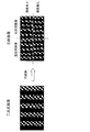
- FIG. 2 is a diagram illustrating an example of conversion from a two-dimensional image to a stereoscopic image by the mobile phone 1.
- FIG. 2 shows an example in which the two-dimensional image shown on the left side of the figure is converted into a stereoscopic image shown on the right side of the figure.
- the illustrated two-dimensional image is an image having a vertical stripe pattern in which black vertical lines and gray vertical lines are alternately arranged.
- the mobile phone 1 generates a left-eye image and a right-eye image from the two-dimensional image, and displays them side by side. At this time, the mobile phone 1 does not shift the image for the left eye and the image for the right eye in the left-right direction as in the past (see FIG. 11), but increases the width of a partial area of the image, Reduce the width of the region. Accordingly, a left-right image shift (parallax) is generated between the left-eye image and the right-eye image without generating an empty area between the left-eye image and the right-eye image, thereby giving the user a stereoscopic effect.
- the position of the line is shifted in the left-right direction, so that a stereoscopic effect can be given to the user. Further, since no empty area is generated between the left-eye image and the right-eye image, the empty area does not give the user a sense of incongruity, and the end portions of the left-eye image and the right-eye image are not lost.
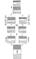
- FIG. 3 is a diagram illustrating another example of conversion from a two-dimensional image to a stereoscopic image by the mobile phone 1.
- FIG. 3 shows an example of converting the two-dimensional image shown at the left end of FIG.
- the illustrated two-dimensional image is an image having a vertical stripe pattern in which vertical lines of dots, white vertical lines, and diagonal vertical lines are arranged.
- the image size adjustment unit 21 of the mobile phone 1 generates a left-eye image and a right-eye image from the two-dimensional image.
- the left-eye image and the right-eye image are both images in which the resolution in the width direction of the original two-dimensional image is halved.
- the image size adjusting unit 21 divides each of the left eye image and the right eye image into a plurality of regions in the width direction.
- each of the left-eye image and the right-eye image is divided into nine parts in the width direction to form nine regions.
- the division of the area means setting an area in the image.
- the image size adjustment unit 21 divides the divided area into a plurality of groups, and increases or decreases the width of the divided area for each group.
- the nine divided areas are divided into three groups each including three divided areas.
- the width of the divided region of the leftmost group is reduced, the width of the divided region of the central group is not changed (equal magnification), and the width of the divided region of the rightmost group is increased.
- the width of the divided region of the leftmost group is enlarged, the width of the divided region of the central group is not changed, and the width of the divided region of the rightmost group is reduced. Note that the enlargement and reduction of the area can be performed by shifting the coordinates of the area.
- the image size adjustment unit 21 sets a plurality of regions having a certain width that are line-symmetric with respect to the boundary line between the images when the right-eye image and the left-eye image are arranged in the width direction. Then, the same image processing (enlargement or reduction processing) is performed on an area located in a line-symmetric position with respect to the boundary line.
- the image size adjustment unit 21 writes the left-eye image and the right-eye image in which the widths of the divided areas are changed in this manner, with the right-eye image positioned on the right side with respect to the left-eye image, and writes the image to the display memory 30.
- the original two-dimensional image an image with a vertical stripe pattern in which vertical lines of dots, white vertical lines, and diagonal vertical lines are arranged
- the original two-dimensional image is viewed in three dimensions.
- FIG. 4 shows an example of an image obtained by enlarging / reducing the width of the divided area generated by the division in the height direction and the width direction.
- the image (right-eye image or left-eye image) is divided into nine equal parts in the height direction, and is divided into nine equal parts in the width direction to form 81 divided regions.
- This divided area is divided into nine groups, each including nine divided areas, upper left, upper, upper right, center left, center, center right, lower left, lower, and lower right.
- the image size adjustment unit 21 sets a group arranged in the width direction among these groups as one group group, and performs enlargement and reduction independently for each group group.
- Each of the three groups is a group group.
- the upper left group is enlarged, the upper group is made the same size, and the upper right group is reduced.
- the central group all groups are set to the same magnification, and for the lower group, the lower left group is reduced, the lower group is set to the same size, and the lower right group is expanded.
- a plurality of group groups are set by dividing in the height direction, and each group of groups is subjected to enlargement / reduction processing independently, so that the stereoscopic effect varies depending on the position in the height direction.
- An image can be generated.
- the mobile phone 1 (specifically, the image size adjustment unit 21) enlarges the width of some divided areas and reduces the width of other divided areas without changing the width of the entire image.
- a parallax is generated between the right-eye image and the left-eye image.
- the region segmentation method and the enlargement / reduction / same size pattern of each segment region cause a parallax between the right-eye image and the left-eye image, and the width of the right-eye image and the left-eye image does not increase or decrease. Any material may be used as long as the above condition is satisfied.
- the stereoscopic image generated by the mobile phone 1 may be as shown in FIG.
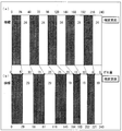
- FIG. 5 is a diagram illustrating an example of a stereoscopic image generated by the mobile phone 1, and illustrates an example of a stereoscopic image in which the parallax at the center is maximized. In the figure, only the right-eye image is shown.
- (A) in the figure shows the image for the right eye before the width change.
- the image for the right eye before the width change is a black and white vertical stripe pattern image having a horizontal width of 24 dots.
- Each white or black line constitutes one divided area. That is, in the illustrated example, the 240-dot width, which is the display area for the right-eye image, is divided into 10 to provide 10 divided areas with a 24-dot width.
- the ten divided areas are divided into two groups, five on the right side and five on the left side.
- the width of each divided region is reduced by 5 dots
- the width of each divided region is increased by 5 dots.
- the right five divided areas have a width of 19 dots
- the left five divided areas have a width of 29 dots.
- the right-eye image that has become a three-dimensional image by changing the width in this way is shifted to the right as compared to before the width change except for both ends.
- the amount of deviation is 5 dots at the boundary between the rightmost white line and the adjacent black line, and is 10 dots at the boundary between the black line and the next white line.
- the deviation amount is 25 dots at the maximum at the boundary line between the 19-dot white line and the 29-dot black line, and decreases as it approaches the left end, and becomes 0 at the left end.
- the shift amount increases by 5 dots, which is a difference from the original width (24 dots), for each divided area. For this reason, in the region corresponding to this group in the right-eye image, the shift amount is accumulated and becomes larger as it approaches the center of the image.
- the shift amount is reduced by 5 dots, which is the difference from the original width (24 dots), for each divided area. For this reason, in the area corresponding to this group in the image for the right eye, the shift amount decreases as it approaches the left end of the image.
- the stereoscopic effect at the position of the boundary line between the 19-dot white line and the 29-dot black line becomes the largest. Then, with the boundary line as the center, the closer to the edge of the screen, the smaller the stereoscopic effect.
- FIG. 6 is a diagram illustrating parallax when the stereoscopic image of FIG. 5 is displayed.
- the right-eye image shown in FIG. 5B is displayed in 240 to 480 dots out of the display width of 480 dots.
- a straight line that divides the display area into two equal parts in the width direction (a straight line that divides the display area with a width of 240 dots) is divided and enlarged symmetrically with the right-eye image.
- a left-eye image that has been subjected to reduction processing is displayed.
- the 240-dot width is divided into 10 to provide 10 divided areas with a 24-dot width, and these 10 divided areas are divided into two groups, five on the right side and five on the left side. ing. For the right group, the width of each divided area is enlarged by 5 dots to 29 dots, and for the left group, the width of each divided area is reduced by 5 dots to 19 dots.
- the parallax barrier allows the right-eye image to be recognized only by the right eye and the left-eye image only by the left eye, so that the image shown in FIG. One such image is recognized three-dimensionally.
- the degree of stereoscopic effect felt by the user at this time is specified by the difference between the right-eye image and the left-eye image, that is, parallax.
- the boundary position (the 211 dot position) between the white line at the right end of the image for the left eye and the black line adjacent thereto is shifted 5 dots to the left. Further, the boundary position (461 dot position) between the white line at the right end of the right-eye image and the black line adjacent thereto is shifted by 5 dots to the right. For this reason, the parallax at the position corresponding to these positions of the image viewed stereoscopically (the boundary position between the white line at the right end and the black line adjacent thereto) is 10, and a stereoscopic effect is generated.
- the parallax is 20 at the boundary position between the next white line and the black line. Also, the closer to the center of the image, the larger the parallax, and the parallax is 50 at the maximum. Then, the closer to the left end of the image from the center of the image, the smaller the parallax, and 0 at the left end of the image.
- the graph is a line graph connecting 0 at the left end of the image, 50 at the center of the image, and 0 at the right end of the image.
- the direction in which the right-eye image and the left-eye image are shifted is reversed, so that the parallax between the two images can be increased.
- the parallax at the center of the image is maximized.
- a stereoscopic image in which a plurality of boundaries between the group to be enlarged and the group to be reduced may be generated. In this case, the parallax at each boundary is maximized.
- the stereoscopic image generated by the mobile phone 1 may be, for example, as shown in FIG.
- FIG. 7 is a diagram illustrating another example of a stereoscopic image generated by the mobile phone 1, and illustrates an example of a stereoscopic image in which the parallax near the end is maximized. In the figure, only the right-eye image is shown. Moreover, (a) of the figure is the same as (a) of FIG.
- the width of each divided area is reduced by 1 dot, and for the left group, the width of the divided area is increased by 9 dots.
- the right nine divided areas have a width of 23 dots, and the leftmost divided area has a width of 33 dots.
- the right-side image is shifted to the right as compared to before the width change except for both ends.
- the amount of deviation is 1 dot at the boundary between the rightmost white line and the adjacent black line, and 2 dots at the boundary between the black line and the next white line. .
- the amount of deviation increases as it approaches the left end, and reaches a maximum of 9 dots at the boundary line between the 23-dot white line and the 33-dot black line. The deviation amount returns to 0 at the left end.
- the amount of deviation increases by one dot, which is the difference from the original width (24 dots), for each divided area. For this reason, in the region corresponding to this group in the image for the right eye, the amount of rightward misalignment increases as it approaches the left end of the image.
- the black line at the left end is enlarged 9 dots from the original width (24 dots), the right end of this black line is shifted 9 dots to the right, and the shift amount at the left end is zero. That is, in the black line area at the left end, the right end shift is the maximum at 9 dots, and the shift becomes smaller as it approaches the left end, and the shift becomes 0 at the left end.
- the position corresponding to the position of the boundary line between the 23-dot white line and the 33-dot black line is 18. This is because the rightward shift amount of the right-eye image is 9, and the leftward shift amount of the left-eye image is 9.
- the parallax is 16 at the boundary position on the right side of the boundary position, and the parallax becomes smaller as it approaches the right end, and becomes 0 at the right end.
- the parallax at the left end is also zero.
- a stereoscopic image with a different stereoscopic effect can be generated by changing a conversion pattern from a two-dimensional image to a stereoscopic image, in particular, a setting pattern of divided areas and an enlargement / reduction pattern.
- a plurality of conversion patterns are prepared in advance, and a stereoscopic image is generated with the conversion pattern selected by the user.
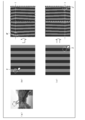
- FIG. 8 is a diagram illustrating an example of conversion patterns that can be selected in the mobile phone 1.
- FIG. 4A shows a conversion pattern in which a stereoscopic effect is generated in the depth direction with respect to the display surface
- FIG. 4B shows a conversion pattern in which a stereoscopic effect is generated in the near direction with respect to the display surface.
- FIG. 4C shows a conversion pattern with a greater sense of depth toward the lower side of the image
- FIG. 4D shows a conversion pattern with a greater sense of depth toward the upper side of the image.
- the line width at the left end of the image for the right eye is enlarged and the line width at the right end is reduced.
- the width of other lines is not changed.
- the eight lines whose widths are not changed are shifted to the right due to the expansion / reduction of the line widths at both ends.
- the right-end line width of the left-eye image is enlarged and the left-end line width is reduced.
- the width of other lines is not changed.
- the eight lines whose widths are not changed are shifted leftward due to the expansion / reduction of the line widths at both ends.
- This conversion pattern is suitable for an image for which it is desirable to generate a three-dimensional effect in the depth direction, such as a landscape photograph shown in the figure.
- the line width at the right end of the image for the right eye is enlarged and the line width at the left end is reduced.
- the width of other lines is not changed.
- the eight lines whose widths are not changed are shifted leftward due to the expansion / reduction of the line widths at both ends.
- the line width at the left end of the image for the left eye is enlarged and the line width at the right end is reduced.
- the width of other lines is not changed.
- the eight lines whose widths are not changed are shifted to the right due to the expansion / reduction of the line widths at both ends.
- This conversion pattern is suitable for an image (such as an image having one main subject) that desirably generates a three-dimensional effect that causes a specific object to pop out, such as the illustrated insect photograph.
- the line width at the right end of the right eye image is reduced toward the lower side of the image, and the line width at the left end is increased toward the lower side of the image.
- the width of other lines is not changed.
- the eight lines whose widths are not changed are tilted to the right by the enlargement / reduction of the line widths at both ends, and are shifted to the right as the lower side of the image.
- the line width at the right end of the image for the left eye is enlarged toward the lower side of the image, and the line width at the left end is reduced toward the lower side of the image.
- the width of other lines is not changed.
- the eight lines whose widths are not changed are tilted to the right by the enlargement / reduction of the line width at both ends, and are shifted to the left as the lower side of the image.
- a partial area of the right-eye image is shifted to the right, and a partial area of the left-eye image is shifted to the left. Therefore, a stereoscopic image in which a stereoscopic effect is generated in the depth direction in this region is obtained. Further, since the shift amount increases toward the lower side of the image, the sense of depth also increases toward the lower side of the image.
- This conversion pattern is an image that is desirable to generate a stereoscopic effect that allows the user to recognize that the lower part is farther away, such as a landscape photograph shown in the figure (an image closer to the user as it appears in the upper part). It is suitable for.
- the line width at the right end of the right-eye image is reduced toward the upper side of the image, and the line width at the left end is increased toward the upper side of the image.
- the width of other lines is not changed.
- the eight lines whose widths are not changed are tilted to the right by the enlargement / reduction of the line widths at both ends, and are shifted to the right as the upper side of the image is increased.
- the line width at the right end of the image for the left eye is enlarged toward the upper side of the image, and the line width at the left end is reduced toward the upper side of the image.
- the width of other lines is not changed.
- the eight lines whose widths are not changed are inclined to the lower right by the enlargement / reduction of the line width at both ends, and are shifted to the left as the upper side of the image.
- a partial area of the right-eye image is shifted to the right, and a partial area of the left-eye image is shifted to the left. Therefore, a stereoscopic image in which a stereoscopic effect is generated in the depth direction in this region is obtained. Further, since the deviation amount increases toward the upper side of the image, the sense of depth also increases toward the upper side of the image.
- This conversion pattern is suitable for an image that is desired to generate a stereoscopic effect that allows the user to recognize that it is farther from the upper part, such as a landscape photograph shown in the figure (an image that is closer to the user as it appears in the lower part). It is.
- the mobile phone 1 may recognize a two-dimensional image that is a source of a stereoscopic image, determine which conversion pattern is suitable, and automatically select the conversion pattern. For example, when a person's face is detected, a conversion pattern that makes the person appear to pop out may be automatically selected.
- FIG. 9 is a diagram showing an example of pattern management information.
- the width direction division number N, the group number M, the height direction division number N ′, and the parallax parameter P are associated with each pattern. Note that these are parameters for generating the right-eye image.
- a conversion pattern that produces a “stereoscopic effect in the depth direction” a conversion pattern that produces a “stereoscopic effect in the front direction”
- a conversion pattern that produces “a large sense of depth on the lower side” a conversion pattern that produces “a large sense of depth on the lower side”
- the conversion pattern in which “three-dimensional effect in the depth direction” is generated has a width direction division number N of 10 and a group number M of 3 (grouping is 1, 8, 1 from the left).
- the number N ′ is zero.
- the parallax parameter P is set to (10, 0, ⁇ 10).
- the right-eye image is divided into 10 in the width direction, and the divided area is divided into three groups. Since the grouping is 1, 8, and 1 from the left, the leftmost divided region and the rightmost divided region are each one group, and the other eight divided regions are the remaining one group. Since the height direction division number N ′ is 0, no division in the height direction is performed.
- the divided area is enlarged or reduced in units of groups. That is, for the leftmost group (group including only the leftmost divided area), the divided area is enlarged so that the width increases by 10, and for the rightmost group (group including only the rightmost divided area), the width is 10 The divided area is reduced so as to decrease.
- the divided areas of the central group (groups including eight divided areas) are not enlarged or reduced, and the positions are shifted in accordance with the enlargement / reduction of the divided areas of the right end group and the left end group.
- a right-eye image that produces a “three-dimensional effect in the depth direction” based on the pattern management information is generated.
- the left-eye image is also generated by the same process, but the parameters are changed so that the right-eye image and the left-eye image are symmetric. Specifically, enlargement / reduction is performed with the parallax parameter P set to ( ⁇ 10, 0, 10). In this example, it is not necessary to change the grouping. However, if necessary, the grouping is changed so that the right-eye image and the left-eye image are symmetrical.
- the parameters for the left-eye image may be included in the pattern management information in advance.
- a right eye image and a left eye image are generated in the same manner as the conversion pattern in which “stereoscopic effect in the depth direction” occurs. That is, in the conversion pattern in which “stereoscopic effect in the front direction” is generated, the divided region is enlarged so that the width of the leftmost group (a group including only the divided region at the leftmost) is reduced by 10. For the rightmost group (a group including only the rightmost divided area), the divided area is reduced so that the width increases by 10.
- the divided areas of the central group are not enlarged or reduced, and the positions are shifted in accordance with the enlargement / reduction of the divided areas of the right end group and the left end group. Similarly, a left-eye image is generated.
- the parallax parameter P is also set for each of the nine groups. Specifically, the parallax parameter P ( ⁇ 5, 0, 5) is set for the three upper groups, and the parallax parameter P (5, 0, ⁇ 5) is set for the three lower groups. ing. In addition, the parallax parameters P (0, 0, 0) are set for the three central groups.
- the right-eye image is divided into 10 in the width direction, and the divided area is divided into three groups. Since the grouping is 1, 8, and 1 from the left, the leftmost divided region and the rightmost divided region are each one group, and the other eight divided regions are the remaining one group.
- the right-eye image is divided into three equal parts in the height direction.
- the above-mentioned three groups are further divided into three groups in the height direction, and a total of nine groups are generated.
- the divided areas may be grouped after the area is divided, as in the width direction.
- the divided area is reduced so that the width at the left end group is reduced by 5, and the width at the right end group is reduced.
- the divided area is expanded so as to increase by five.
- the divided area of the central group is not enlarged or reduced, and the position is shifted in accordance with the enlargement / reduction of the divided areas of the right end group and the left end group.
- the divided region is enlarged so that the width is increased by 5 for the left end group, and for the right end group
- the divided area is reduced so that the width is reduced by 5.
- the divided area of the central group is not enlarged or reduced, and the position is shifted in accordance with the enlargement / reduction of the divided areas of the right end group and the left end group.
- an image for the right eye with a “large depth feeling on the lower side” based on the pattern management information is generated.
- the left-eye image is also generated by the same processing, but enlargement / reduction is performed by reversing the sign of the parallax parameter P so that the right-eye image and the left-eye image are symmetric.
- a right eye image and a left eye image are generated in the same manner as a conversion pattern in which “lower depth feeling is large”.
- Such pattern management information may be editable by the user via the stereoscopic display control unit 20, for example.
- the user can include a desired conversion pattern in the pattern management information, and can display a stereoscopic image corresponding to the conversion pattern on the mobile phone 1.
- FIG. 10 is a diagram illustrating a method for generating a stereoscopic image in which the stereoscopic effect at the specified position is increased.
- the figure (a) has shown the mode of the position selection on a two-dimensional image.
- FIG. 5B shows an example of a stereoscopic image generated when a position near the upper left is selected
- FIG. 10C shows a stereoscopic image generated when a position near the lower right is selected. An example is shown.
- the two-dimensional image is first displayed.
- the position designation in the two-dimensional image may be performed by a touch operation on the displayed image. If the touch panel method is not used, a pointer or the like may be displayed and selected using this pointer, and the position designation receiving method is not particularly limited.
- the stereoscopic display control unit 20 specifies the position received by the input unit 4 as the position that maximizes the stereoscopic effect in the right-eye image or the left-eye image. . In addition, you may specify this position as a coordinate on the display surface of the display part 5, for example.
- the image is enlarged / reduced with a conversion pattern that maximizes the parallax at p ′.
- a conversion pattern as shown in FIG. 7B, the divided region on the left side of p ′ is reduced, and the divided region on the right side of p ′ is evenly enlarged so as to fill this reduced portion. Good. This maximizes the parallax of p ′ in the width direction.
- the image is enlarged / reduced with a conversion pattern in which the parallax becomes smaller as the distance from the straight line l increases so that the parallax of the p ′ is maximized also in the height direction.
- a conversion pattern as shown in FIG. 8C is applied to the upper side of the straight line l
- a conversion pattern as shown in FIG. 8D is applied to the lower side of the straight line l. That is, the image is divided in the height direction, divided region groups arranged in the width direction at the same height are set, and the parallax parameter of each divided region group is set smaller as the distance from the straight line l increases. Then, a right-eye image symmetric with the left-eye image generated in this way is generated, and these are displayed side by side.
- the divided region on the right side of p ′ is reduced (in the case of the image for the right eye), and the divided region on the left side of p ′ is evenly arranged so as to fill this reduced portion. It is expanding. Further, the conversion pattern as shown in FIG. 8C is applied to the upper side of the straight line l, and the conversion pattern as shown in FIG. Is adjusted. Then, a left-eye image symmetric with the right-eye image generated in this way is generated, and these are displayed side by side.
- the generation of the stereoscopic image is performed by the image size adjusting unit 21 notified of the position where the stereoscopic effect is maximized from the stereoscopic display control unit 20. Then, the generation of the stereoscopic image includes processing for dividing and grouping images (right-eye image or left-eye image), and enlarging / reducing a divided region for each group.
- an image is divided into N parts in the width direction to define divided areas.
- division in the height direction is performed. Specifically, a divided region having a predetermined height is set around a straight line l (a horizontal straight line passing through a point p ′ corresponding to a designated position p). Note that the divided region through which the straight line l passes is called a central region, and the height of the central region is represented as h.
- the central region is divided into a group on the right side of p ′ and a group on the left side of p ′. Note that the divided region including p ′ may be included in any group or another group.
- the divided regions of each group are enlarged or reduced.
- the divided group of the right group is expanded (or reduced) by P / n dots, respectively.
- the divided area of the left group is reduced (or expanded) by P / m dots, respectively.
- this divided area is set to the same magnification.
- the remaining dots may be offset on both the expansion side and the reduction side.
- the remaining 1 dot may be canceled out
- the divided area of the right group may be expanded by 3 dots
- 5 divided areas of the left group may be reduced by 1 dot
- 2 may be reduced by 2 dots.
- the parallax parameter of p ′ is 9, but the number of divided areas whose width is adjusted can be reduced.
- the parallax parameter may be determined from the common multiple of the number of divided areas included in each group. This eliminates the need for adjusting the remaining dots as described above. For example, when the right group is composed of two divided regions and the left group is composed of eight divided regions, 8 which is a common multiple of 2 and 8 may be used as the parallax parameter P. In this case, each divided region included in the right group is expanded (or reduced) by 4 dots, and each divided region included in the left group is reduced (or expanded) by 1 dot.
- the parallax parameter in the region above the straight line l is determined.
- the parallax parameter of the uppermost divided area of the image farthest from the straight line l is set to zero. That is, neither enlargement nor reduction is performed for this area.
- the divided area closer to the central area is closer to 0, and the divided area closer to the upper edge is closer to the central area.
- the parallax parameter is determined.
- the upper divided region is separated from the central region by one (parallax parameter of the central region) / A parallax parameter that is smaller by x may be determined.
- a parallax parameter that is smaller by (parallax parameter of the central region) / y may be determined every time one is separated from the central region.
- the parallax parameter of the divided area immediately above the central area is 5, and the upper divided area (the upper division of the image)
- the (region) parallax parameter is determined to be 0.
- the parallax parameters may be determined as 8, 6, 4, 3, 2, 1, 0, for example, in order from the divided region immediately below the central region.
- the parallax parameters may be determined as 9, 8, 7, 6, 5, 4, 3 in order from the divided area immediately below the central area.
- the parallax parameter in the region below the straight line l is also determined. Then, according to the parallax parameter determined in this way, each divided region is enlarged / reduced, thereby generating a stereoscopic image in which the stereoscopic effect at p ′ is maximized in the image.
- the parallax parameters of the divided regions at the upper end and the lower end of the image are set to 0 is shown.
- the parallax increases from the upper end and the lower end of the image toward p ′ in the height direction.
- the parallax parameters of these divided areas are not limited to zero.
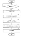
- FIG. 11 is a flowchart illustrating an example of processing (image generation method) executed by the mobile phone 1.
- the stereoscopic display control unit 20 determines whether or not to perform 3D display (stereoscopic display) (S1).
- the trigger for performing the stereoscopic display is not particularly limited, it is determined here that the stereoscopic display control unit 20 performs the stereoscopic display when the user performs an input operation for performing the stereoscopic display on the input unit 4.
- An example will be described.
- the image that is the target of the stereoscopic display is not particularly limited, here, among the images stored in the image storage unit 11, an image set for standby (an image displayed when waiting for an incoming call or the like) is stereoscopically displayed. An example of a display target will be described.
- the stereoscopic display control unit 20 selects a conversion pattern used for generating a stereoscopic image (S2).
- the selection method of this conversion pattern is not specifically limited, either, Here, the three-dimensional display control part 20 presents the four conversion patterns shown in FIG. 8, FIG. And the conversion pattern which the user selected from the input operation which the input part 4 received is specified, and this conversion pattern is selected.
- the stereoscopic display control unit 20 that has selected the conversion pattern notifies the image size adjustment unit 21 of the selected conversion pattern.
- the stereoscopic display control unit 20 turns on the parallax barrier of the display unit 5. Note that the timing for turning on the parallax barrier is not limited to this, and may be, for example, when the generation of the stereoscopic image is completed. Then, the image size adjustment unit 21 reads various parameters of the notified conversion pattern from the pattern management information in the management information storage unit 10.
- the image size adjustment unit 21 reads out a standby image to be stereoscopically displayed from the image storage unit 11, generates a right-eye image and a left-eye image, and sets the generated right-eye image and left-eye image to N.
- Divide (S3) Note that N is a parameter read from the pattern management information.
- the image size adjusting unit 21 divides the right-eye image and the left-eye image into N groups each divided into N groups (S4, area setting step).
- This M is also a parameter read from the pattern management information. Further, the breakdown of the M group (how many divided regions are included in which group) is also specified from the pattern management information.
- the image size adjustment unit 21 generates a stereoscopic image by enlarging or reducing the image of the divided region for each group (S5, image generation step). Note that how much of each group is enlarged or reduced, and the same magnification, are specified from the parallax parameter P of each group described in the pattern management information.
- the image size adjustment unit 21 writes the generated stereoscopic image in the display memory 30 so that the right-eye image is on the right side and the left-eye image is on the left side.
- a stereoscopic image corresponding to the conversion pattern selected in S2 is displayed as a standby image (S6).
- the mobile phone 1 has been described as an example.
- the present invention can be applied to any device that displays a stereoscopic image by a parallax barrier type.
- the present invention can be applied to a smartphone, a tablet terminal, a PDA (Personal Digital Assistance), a portable game machine, and the like.
- the above-described mobile phone 1 displays the generated stereoscopic image on its own device
- the stereoscopic image may be displayed on another device.
- the present invention can also be understood as an image generation device that generates a stereoscopic image.
- the above-described image generation method may be executed by a device (image generation device) that can communicate with a display device having a stereoscopic image display function using a parallax barrier method. Then, the generated stereoscopic image may be transmitted to the display device and displayed.
- an example is shown in which an image is grouped after being divided into N, but a group may be set without being divided into N.
- a group having a width of 10%, a group having a width of 80%, and a group having a width of 10% are set. Good.
- each block of the mobile phone 1, in particular, the stereoscopic display control unit 20 and the image size adjustment unit 21 may be realized in hardware by a logic circuit formed on an integrated circuit (IC chip), or a CPU (Central Processing Unit) may be used for software implementation.
- IC chip integrated circuit
- CPU Central Processing Unit
- the mobile phone 1 includes a CPU that executes instructions of a program that realizes each function, a ROM (Read Memory) that stores the program, a RAM (Random Memory) that develops the program, the program, and various types
- a storage device such as a memory for storing data is provided.
- An object of the present invention is to provide a recording medium on which a program code (execution format program, intermediate code program, source program) of a control program for the mobile phone 1 which is software for realizing the above-described functions is recorded so as to be readable by a computer. This can also be achieved by supplying the mobile phone 1 and reading and executing the program code recorded on the recording medium by the computer (or CPU or MPU).
- Examples of the recording medium include tapes such as magnetic tapes and cassette tapes, magnetic disks such as floppy (registered trademark) disks / hard disks, and disks including optical disks such as CD-ROM / MO / MD / DVD / CD-R.
- IC cards including memory cards
- semiconductor memories such as mask ROM / EPROM / EEPROM / flash ROM, or PLD (Programmable logic device) or FPGA (Field Programmable Gate Array) Logic circuits can be used.
- the mobile phone 1 may be configured to be connectable to a communication network, and the program code may be supplied via the communication network.
- the communication network is not particularly limited as long as it can transmit the program code.
- the Internet intranet, extranet, LAN, ISDN, VAN, CATV communication network, virtual private network, telephone line network, mobile communication network, satellite communication network, and the like can be used.
- the transmission medium constituting the communication network may be any medium that can transmit the program code, and is not limited to a specific configuration or type.
- wired lines such as IEEE 1394, USB, power line carrier, cable TV line, telephone line, ADSL (Asymmetric Digital Subscriber Line) line, infrared rays such as IrDA and remote control, Bluetooth (registered trademark), IEEE 802.11 wireless, HDR ( It can also be used by radio such as High Data Rate (NFC), Near Field Communication (NFC), Digital Living Network Alliance (DLNA), mobile phone network, satellite line, and digital terrestrial network.
- the present invention can also be realized in the form of a computer data signal embedded in a carrier wave in which the program code is embodied by electronic transmission.
- the image generating apparatus of the present invention includes a region setting unit that sets a plurality of regions having a certain width by dividing at least one of the right-eye image and the left-eye image in the width direction, and the region setting unit.
- Image generating means for reducing at least one of the set areas in the width direction and generating a stereoscopic image in which the width of at least one other area is enlarged by the reduced width.
- the region setting unit may divide each of the right-eye image and the left-eye image in the width direction and arrange the right-eye image and the left-eye image in the width direction.
- a plurality of regions having a certain width that are line-symmetric with respect to the boundary line between the two images are set, and the image generation means is symmetric with at least one of the regions set in the right-eye image and the region.
- An area set in the left eye image is reduced in the width direction, and at least one other area set in the right eye image by the reduced width and an area set in the left eye image symmetrical to the area It is preferable to increase the width.
- a symmetric area is set for the right-eye image and the left-eye image, and the symmetric area is similarly reduced and enlarged.
- the stereoscopic image generated in this way becomes larger by adding the shift amount in the width direction of the right-eye image and the left-eye image in both images.
- the portion from the area A to the area B is shifted to the right side.
- the region A ′ that is symmetrical to the region A is reduced, and the region B ′ that is symmetrical to the region B and located on the right side of the region A ′ is enlarged.
- the part up to B ' is shifted to the left.
- the image generating means may be configured to reduce one of adjacent regions in the width direction and expand the other in the width direction.
- one of the adjacent regions is reduced in the width direction and the other is enlarged in the width direction.
- the amount of deviation increases in the reduced region as it approaches the enlarged region, and the amount of deviation increases in the enlarged region as it approaches the reduced region.
- the shift amount that is, the parallax is maximized at a portion where the reduced region and the enlarged region are in contact, and the parallax decreases as the distance from the portion increases. Therefore, according to the above configuration, it is possible to generate a stereoscopic image in which the parallax becomes maximum at a certain point in the width direction, and the parallax decreases as the distance from the point in the width direction increases.
- the region setting unit sets three regions that are continuous in the width direction in at least one of the right-eye image and the left-eye image, and the image generation unit Of these, the region located in the center may be configured such that the width is not changed, one region adjacent to the region is reduced in the width direction, and the other region is expanded in the width direction.
- three regions that are continuous in the width direction are set in one image, and the region located in the center of the three regions is not changed in width, and is one region adjacent to the region. Decreases in the width direction, and the other region expands in the width direction.
- the center area is shifted in the width direction due to the enlargement / reduction of both adjacent areas, but the shift amount does not increase or decrease in the center area. That is, according to the above configuration, it is possible to generate a stereoscopic image in which the parallax is constant within the central region.
- the above configuration includes the case where four or more areas are set.
- the area other than the three consecutive areas may be changed or not changed as long as there is no increase / decrease in the width as a whole.
- the region setting means sets a plurality of region groups having a certain height by dividing at least one of the right-eye image and the left-eye image in the height direction, It is preferable that the image generation means independently performs area enlargement and reduction for each area group set by the area setting means.
- a plurality of area groups having a certain height are set by dividing the image in the height direction, and the area is expanded and reduced independently for each set area group.
- different parallax may be generated depending on the position in the height direction.
- a stereoscopic image in which different parallax occurs depending on the position in the height direction. For example, it is possible to generate a stereoscopic image having a greater stereoscopic effect on the upper side and a stereoscopic image having a greater stereoscopic effect on the lower side than the upper side.
- the image generation device is configured to specify a position in the right-eye image or the left-eye image specified by the user from an input unit that receives the user's input operation and the input operation that is received by the input unit.
- the area setting means sets an adjacent area at the position specified by the position specifying means according to the division in the width direction, and the image generation means reduces one of the adjacent areas in the width direction. However, it is preferable to enlarge the other in the width direction.
- an adjacent area is set at the position specified by the position specifying means, one of the adjacent areas is reduced in the width direction, and the other is enlarged in the width direction. For this reason, in the generated stereoscopic image, the parallax at the position specified by the position specifying unit is maximized in the width direction.
- the position specified by the position specifying means is a position specified by the user.
- a stereoscopic image in which the parallax at the position specified by the user is maximized in the width direction is generated. Therefore, according to the above configuration, the user can specify an arbitrary position in the image via the input unit and generate a stereoscopic image in which the parallax at this position is maximized in the width direction.
- the image generation device is configured to specify a position in the right-eye image or the left-eye image specified by the user from an input unit that receives the user's input operation and the input operation that is received by the input unit.
- the region setting unit sets a specific region group that is a region group including the position specified by the position specifying unit according to the height direction division, and the image generation unit includes the specific region group.
- the area is expanded and contracted, and the area group other than the specific area group set by the height direction division is set so that the parallax at the position specified by the position specifying unit is maximized in the height direction. It is preferable to perform reduction and enlargement in the width direction.
- the specific area group that is the area group including the position specified by the position specifying means is set by the division in the height direction. Then, the area of the specific area group is enlarged and reduced, and the parallax at the position specified by the position specifying means is maximized in the height direction for the area group other than the specific area group set by the height direction division. As described above, reduction and enlargement in the width direction of the region are performed. For this reason, in the generated stereoscopic image, the parallax at the position specified by the position specifying means is maximized in the height direction.
- the position specified by the position specifying means is a position specified by the user.
- a stereoscopic image in which the parallax at the position specified by the user is maximized in the height direction is generated. Therefore, according to the above configuration, the user can specify an arbitrary position in the image via the input unit and generate a stereoscopic image in which the parallax at this position is maximum in the height direction.
- the image generation apparatus may be realized by a computer.
- an image generation program for realizing the image generation apparatus by a computer by causing the computer to operate as each unit of the image generation apparatus In addition, a computer-readable recording medium on which it is recorded also falls within the scope of the present invention.
- the present invention can be used for an apparatus that generates a stereoscopic image and an apparatus that generates and displays a stereoscopic image.
Landscapes
- Engineering & Computer Science (AREA)
- Multimedia (AREA)
- Signal Processing (AREA)
- Physics & Mathematics (AREA)
- Computer Hardware Design (AREA)
- General Physics & Mathematics (AREA)
- Theoretical Computer Science (AREA)
- Testing, Inspecting, Measuring Of Stereoscopic Televisions And Televisions (AREA)
Abstract
携帯電話機(1)は、右目用画像及び左目用画像を幅方向に区分して一定の幅を有する複数の領域を設定し、設定した領域の少なくとも1つを幅方向に縮小し、縮小した幅だけ他の少なくとも1つの領域の幅を拡大した立体画像を生成する画像サイズ調整部(21)を備えている。
Description
本発明は、二次元画像から、視差バリア式の表示装置で立体視が可能な立体画像を生成する画像生成装置等に関する。
近年、立体画像(立体視が可能な画像)を表示する装置に注目が集まっている。立体画像を表示する装置としては、様々なものが知られているが、多くの装置は視聴者の右目に見える画像と、左目に見える画像とに視差をつけることによって立体視を可能にする。例えば、二眼のカメラを用いて撮影した、右目用の画像を視聴者の右目のみで視認させ、左目用の画像を視聴者の左目のみで視認させることによって、立体感を与えるテレビ等が市販されている。
その一方で、例えば、下記特許文献1、2に記載のように、通常の(二眼ではない)カメラなどで撮影した二次元画像を立体画像に変換することによって、簡易な立体視を可能にする方法も知られている。
具体的には、特許文献1には、二次元画像のデータを解析することで視差をつける位置・大きさを解析し、この解析結果に応じて距離情報を付与することによって、二次元画像に立体感を付与することが記載されている。
また、特許文献2には、カメラ撮影時の情報を元に視差をつける位置・大きさを解析し、この解析結果に応じて視差情報を付与することによって、二次元画像に立体感を付与することが記載されている。
さらに、1つの二次元画像から、左目用画像と右目用画像からなる立体画像を生成する方法も知られている。これについて、図12に基づいて説明する。図12は、1つの二次元画像から、左目用画像と右目用画像からなる立体画像を生成する方法を説明する図である。
この方法では、まず、元の二次元画像から、水平方向の解像度が元の二次元画像の1/2である2つの画像を生成し、この一方を左目用画像とし、他方を右目用画像とする。この左目用画像と、右目用画像は、元の二次元画像を水平方向(画像の幅方向)に1/2に縮小した画像である。
これらの画像を、表示面の右半分をユーザの右目のみに視認させ、左半分をユーザの左目のみに視認させる視差バリアを介して見れば、左目用画像はユーザの左目のみに認識され、右目用画像はユーザの右目のみに認識される。つまり、この左目用画像と右目用画像を並べて、視差バリア式の表示装置に表示した場合の見え方は、図示のように元の二次元画像と同じとなる。
このような右目用画像と左目用画像を用いてユーザに立体視させるためには、右目用画像と左目用画像とに視差を生じさせる必要がある。そこで、図示のように、左目用画像は水平方向(画像の幅方向)左向きにずらし、右目用画像は水平方向右向きにずらした画像を立体画像として表示する。
そして、このような立体画像(水平方向にずらした左目用画像と右目用画像)を、視差バリアを介して見れば、図示のような奥行き感を感じる。なお、左目用画像を水平方向右向きにずらし、右目用画像を水平方向左向きにずらしてもよく、この場合、画像は表示面よりも手前側に飛び出して認識される。
しかしながら、上述のような従来技術では、左目用画像と右目用画像をずらしているため、図12に示すように、立体画像の中央(左目用画像の右端及び右目用画像の左端)に空き領域が生じる。そして、これにより、ユーザに認識される立体像の両端にも空き領域(画像が表示されない領域)が生じ、立体視するユーザに違和感を与えてしまうという問題がある。この空き領域に基づく違和感は、表示面の全面に画像を表示する場合に特に大きい。表示面の両端部と画像の両端部が一致しないためである。
また、右目用画像を右にずらしたことによって、右目用画像の右端部分は表示されず、同様に、左目用画像を左にずらしたことによって、左目用画像の左端部分は表示されなくなってしまう。つまり、図12のようにして生成した立体画像では、ずらす前の左目用画像及び右目用画像の両端部が欠けてしまう。
これは、左目用画像を水平方向右向きにずらし、右目用画像を水平方向左向きにずらした場合(手前方向に立体感を出す場合)にも生じる問題である。この場合には、右目用画像の右側と、左目用画像の左側に空き領域が生じ、右目用画像の左端と、左目用画像の右端が欠けてしまう。
ここで、例えば、右目用画像と左目用画像とを拡大することによって、上記の空白領域を埋めることも考えられるが、この方法では自然な立体感が得られない場合がある。例えば、奥行き方向に立体感を出すように画像をずらすと共に、画像の拡大を行った場合に、所望の奥行き感が感じられないおそれがある。画像の拡大はユーザに画像が近付いたような認識を与えるためである。また、画像を拡大する方法では、画像の端部が欠ける問題が解決されない。
本発明は、上記の問題点に鑑みてなされたものであり、その目的は、空白領域を発生させず、また画像の欠けを発生させずに立体画像を生成する画像生成装置等を提供することにある。
上記の課題を解決するために、本発明の画像生成装置は、ユーザの右目のみに視認させる右目用画像と、左目のみに視認させる左目用画像とからなり、視差バリア式の表示装置に表示させることによって、上記ユーザに立体感を与える立体画像を生成する画像生成装置であって、上記右目用画像及び上記左目用画像の少なくとも一方を幅方向に区分して一定の幅を有する複数の領域を設定する領域設定手段と、上記領域設定手段が設定した領域の少なくとも1つを幅方向に縮小し、縮小した幅だけ他の少なくとも1つの領域の幅を拡大した立体画像を生成する画像生成手段とを備えていることを特徴としている。
また、本発明の画像生成方法は、上記の課題を解決するために、ユーザの右目のみに視認させる右目用画像と、左目のみに視認させる左目用画像とからなり、視差バリア式の表示装置に表示させることによって、上記ユーザに立体感を与える立体画像を生成する画像生成装置による画像生成方法であって、上記右目用画像及び上記左目用画像の少なくとも一方を幅方向に区分して一定の幅を有する複数の領域を設定する領域設定ステップと、上記領域設定ステップで設定した領域の少なくとも1つを幅方向に縮小し、縮小した幅だけ他の少なくとも1つの領域の幅を拡大した立体画像を生成する画像生成ステップとを含むことを特徴としている。
上記の構成によれば、画像を幅方向に区分して一定の幅を有する複数の領域を設定する。そして、設定した領域の少なくとも1つを幅方向に縮小し、縮小した幅だけ他の少なくとも1つの領域の幅を拡大した立体画像を生成する。
このようにして生成された立体画像は、拡大・縮小前の画像に対して幅方向にずれた画像となる。例えば、右目用画像のある領域を縮小し、この領域に対して左側に位置する領域を拡大した場合、縮小した領域から拡大した領域までの部分は右側にずれる。なお、幅方向とは、視差バリアのスリットが延在する方向に対して垂直な方向である。
したがって、このずれた部分については、右目用画像と左目用画像とで視差が生じる。よって、視差バリアを介してこの立体画像を見るユーザには、この部分が立体的に認識される。また、上記の構成によれば、ある領域を縮小した幅だけ他の領域の幅を拡大するので、画像全体の幅は変わらない。
したがって、上記の構成によれば、空白領域を発生させず、また画像の欠けを発生させずに立体画像を生成することができる。
以上のように、本発明の画像生成装置は、右目用画像及び左目用画像の少なくとも一方を幅方向に区分して一定の幅を有する複数の領域を設定する領域設定手段と、上記領域設定手段が設定した領域の少なくとも1つを幅方向に縮小し、縮小した幅だけ他の少なくとも1つの領域の幅を拡大した立体画像を生成する画像生成手段とを備えている構成である。
また、本発明の画像生成方法は、右目用画像及び左目用画像の少なくとも一方を幅方向に区分して一定の幅を有する複数の領域を設定する領域設定ステップと、上記領域設定ステップで設定した領域の少なくとも1つを幅方向に縮小し、縮小した幅だけ他の少なくとも1つの領域の幅を拡大した立体画像を生成する画像生成ステップとを含む構成である。
したがって、空白領域を発生させず、また画像の欠けを発生させずに立体画像を生成することができる。
以下、本発明の実施の形態について、図1~図11に基づいて詳細に説明する。
〔携帯電話機の要部構成〕
まず、本実施形態の携帯電話機の要部構成を図1に基づいて説明する。図1は、携帯電話機(画像生成装置)1の要部構成の一例を示すブロック図である。
まず、本実施形態の携帯電話機の要部構成を図1に基づいて説明する。図1は、携帯電話機(画像生成装置)1の要部構成の一例を示すブロック図である。
携帯電話機1は、立体画像を表示することのできる携帯電話機であり、記憶部2、制御部3、入力部4、及び表示部(表示装置)5を備えている。なお、携帯電話機1は、図示した構成の他にも、通話や電子メールの送受信等のための構成を備えているが、これらの構成については省略している。
記憶部2は、携帯電話機1で使用するデータを記憶するものであり、管理情報格納部10と画像格納部11を含む。
管理情報格納部10には、表示部5の視差バリアを介して見るユーザに立体感を与える立体画像を生成するための各種パラメータを含むパターン管理情報が格納される。なお、パターン管理情報の詳細については後述する。
画像格納部11には、表示部5に表示する画像が格納される。なお、画像格納部11に格納される画像は二次元画像であり、携帯電話機1はこの二次元画像から立体画像を生成する。つまり、携帯電話機1では、立体視のために、特別な画像を用意する必要はなく、一眼のカメラで撮影した通常の二次元画像等を用意すればよい。なお、格納する画像は写真でなくともよい。
制御部3は、携帯電話機1の動作を統括して制御するものであり、立体表示制御部20(位置特定手段)と画像サイズ調整部(領域設定手段、画像生成手段)21を含む。
立体表示制御部20は、入力部4が受け付けた入力操作に応じて、立体画像を表示するための制御を行う。また、管理情報格納部10に格納されているパターン管理情報から、立体画像の生成に用いる変換パターンを指定する。さらに、入力部4が受け付けた入力操作に基づき、立体画像中で視差を大きく設定する位置を特定し、この位置を画像サイズ調整部21に通知する。
画像サイズ調整部21は、二次元画像に画像処理を施して立体画像を生成する。具体的には、まず、立体画像の元になる二次元画像を画像格納部11から読み出し、この二次元画像から、左目用画像と右目用画像を生成する。つまり、サイドバイサイド(Side by Side)方式の立体画像を生成する。
次に、画像サイズ調整部21は、立体表示制御部20に指定された変換パターンに従って、この右目用画像及び左目用画像を幅方向に区分して一定の幅を有する複数の領域を設定する。そして、設定した領域の少なくとも1つを幅方向に縮小し、縮小した幅だけ他の少なくとも1つの領域の幅を拡大した立体画像を生成する。
詳細については後述するが、これにより、右目用画像及び左目用画像の幅を全体としては変えることなく、右目用画像と左目用画像で視差のある、つまり立体的に認識される立体画像が生成される。
なお、制御部3の機能を実現する処理ブロックは、図1の例に限られない。例えば、ここでは、領域の設定及び領域の拡大・縮小の処理を画像サイズ調整部21が行う例を説明するが、これらの処理は別のブロックで行うようにしてもよい。立体表示制御部20についても同様であり、立体表示制御部20の実行する処理の一部を他のブロックが実行する構成としてもよい。
入力部4は、ユーザの入力操作を受け付けるものである。入力部4は、表示部5と独立した入力ボタン等で構成してもよいし、表示部5の表示面に対する入力操作を受け付けるタッチパネル等で構成してもよい。
表示部5は、視差バリア式の表示部、すなわち視差バリアを有する表示部であり、表示対象となる画像を格納する表示メモリ30を含む。ここでは、表示部5は、立体表示制御部20の制御に従って、視差バリアのON/OFFを切り替える機能を有している例を説明する。つまり、表示部5は、二次元画像を表示するときには、視差バリアOFFにされ、立体画像を表示するときには視差バリアONにされる。
なお、視差バリアとは、表示した画像のうち、表示面の正面から画像を見るユーザの右目には右目のみで認識させる部分(右目用画像)が視認されるようにし、左目には左目のみで認識させる部分(左目用画像)が視認されるようにするものである。ここでは、画面中央を境界として、左目用画像をその左に、右目用画像をその右に表示することを想定している。このため、視差バリアはユーザの右目には画面中央より右側のみが視認され、左目には画面中央より左側のみが視認されるように、ユーザの視線を遮るものとなる。
〔二次元画像から立体画像への変換の概要〕
次に、携帯電話機1による二次元画像から立体画像への変換の概要を図2に基づいて説明する。図2は、携帯電話機1による二次元画像から立体画像への変換の一例を示す図である。
次に、携帯電話機1による二次元画像から立体画像への変換の概要を図2に基づいて説明する。図2は、携帯電話機1による二次元画像から立体画像への変換の一例を示す図である。
図2では、同図の左側に示す二次元画像を、同図の右側に示す立体画像に変換する例を示している。図示の二次元画像は、黒の縦ラインとグレーの縦ラインが交互に並ぶ縦縞模様の画像である。
携帯電話機1は、この二次元画像から左目用画像と右目用画像を生成し、これらを並べて表示する。この際、携帯電話機1は、従来のように左目用画像と右目用画像を左右方向にずらすのではなく(図11参照)、画像の一部の領域についてその幅を増加させ、他の一部の領域についてその幅を減少させる。これにより、左目用画像と右目用画像の間に空き領域を生じさせることなく、左目用画像と右目用画像の間に左右方向のずれ(視差)を生じさせて、ユーザに立体感を与える。
図2の例では、画像の下半分にはずれを生じさせていない。つまり、画像の下半分は、図12に示したように、ユーザには二次元画像として認識される。一方、画像の上半分には、左右方向のずれを生じさせている。より詳細には、左目用画像の左端のライン幅を減少させ、右端のライン幅を増加させることにより、他のラインを左側にずらしている。同様に、右目用画像の左端のライン幅を増加させ、右端のライン幅を減少させることにより、他のラインを右側にずらしている。
このように、3D変換で生成された立体画像では、ラインの位置が左右方向にずれているので、ユーザに立体感を与えることができる。また、左目用画像と右目用画像の間に空き領域を生じさせないので、空き領域がユーザに違和感を与えることもなく、左目用画像と右目用画像の端部が欠けることもない。
〔二次元画像から立体画像への変換の詳細〕
続いて、携帯電話機1による二次元画像から立体画像への変換の詳細を図3に基づいて説明する。図3は、携帯電話機1による二次元画像から立体画像への変換の他の例を示す図である。
続いて、携帯電話機1による二次元画像から立体画像への変換の詳細を図3に基づいて説明する。図3は、携帯電話機1による二次元画像から立体画像への変換の他の例を示す図である。
図3では、同図の左端に示す二次元画像を立体画像に変換する例を示している。図示の二次元画像は、ドットの縦ライン、白の縦ライン、及び斜線の縦ラインが並ぶ縦縞模様の画像である。
まず、携帯電話機1の画像サイズ調整部21は、この二次元画像から左目用画像と右目用画像を生成する。ここでは、サイドバイサイド方式の立体画像を生成することを想定しているので、左目用画像及び右目用画像は、何れも元の二次元画像の幅方向の解像度を1/2にした画像となる。
続いて、画像サイズ調整部21は、左目用画像及び右目用画像のそれぞれを、幅方向に複数の領域に分割する。図示の例では、左目用画像及び右目用画像のそれぞれを幅方向に9等分して9つの領域としている。なお、領域の分割とは、画像中に領域を設定することを意味する。また、同図では二次元画像の柄の変わり目と分割線が一致しているが、必ずしもこれらを一致させる必要はない。
次に、画像サイズ調整部21は、分割領域を複数のグループに分け、グループ毎に分割領域の幅を増加または減少させる。図示の例では、9つの分割領域を、それぞれが3つの分割領域を含む3つのグループに分けている。そして、左目用画像では、左端のグループの分割領域の幅を縮小し、中央のグループの分割領域の幅は変えず(等倍)、右端のグループの分割領域の幅を拡大している。一方、右目用画像では、左端のグループの分割領域の幅を拡大し、中央のグループの分割領域の幅は変えず、右端のグループの分割領域の幅を縮小している。なお、領域の拡大及び縮小は、領域の座標をシフトさせることによって行うことができる。
つまり、画像サイズ調整部21は、右目用画像及び該左目用画像を幅方向に並べたときの両画像の境界線に対して線対称となる、一定の幅を有する複数の領域を設定する。そして、この境界線に対して線対称の位置にある領域には、同じ画像処理(拡大または縮小処理)を施す。
そして、画像サイズ調整部21は、分割領域の幅をこのように変更した左目用画像及び右目用画像を、左目用画像に対して右目用画像が右側に位置するように並べて表示メモリ30に書き込み、表示部5に表示させる。この画像を表示部5の視差バリアを介して見ることにより、元の二次元画像(ドットの縦ライン、白の縦ライン、及び斜線の縦ラインが並ぶ縦縞模様の画像)が立体的に視認される。
〔高さ方向の分割について〕
上記では、画像を幅方向にのみ分割する例を説明したが、高さ方向(垂直方向)にも分割してもよい。これについて、図4に基づいて説明する。図4は、高さ方向及び幅方向への分割によって生じた分割領域の幅を拡大・縮小した画像の例を示している。
上記では、画像を幅方向にのみ分割する例を説明したが、高さ方向(垂直方向)にも分割してもよい。これについて、図4に基づいて説明する。図4は、高さ方向及び幅方向への分割によって生じた分割領域の幅を拡大・縮小した画像の例を示している。
図示の例では、画像(右目用画像または左目用画像)を高さ方向に9等分すると共に、幅方向にも9等分して81個の分割領域としている。そして、この分割領域を、それぞれが9つの分割領域を含む、左上、上、右上、中央左、中央、中央右、左下、下、右下の9つのグループに分けている。
画像サイズ調整部21は、これらのグループのうち、幅方向に並ぶグループを1つのグループ群とし、グループ群ごとに拡大及び縮小を独立に行う。図示の例では、左上、上、右上の3つのグループ(上グループ群)、中央左、中央、中央右の3つのグループ(中央グループ群)、及び左下、下、右下(下グループ群)の3つのグループをそれぞれグループ群としている。
そして、上グループ群については、左上のグループを拡大し、上のグループを等倍とし、右上のグループを縮小している。また、中央グループ群については、何れのグループも等倍とし、下グループ群については、左下のグループを縮小し、下のグループを等倍とし、右下のグループを拡大している。
これにより、上グループ群の画像は右にずれ、中央グループ群の画像はずれがなく、下グループ群の画像は左にずれる。したがって、この画像が右目用画像であった場合、上グループ群の部分は表示面よりも奥側に、中央グループ群の部分は表示面上に、下グループ群の部分は表示面から飛び出して認識される。
すなわち、高さ方向にも分割を行って複数のグループ群を設定し、各グループ群のグループに対して、独立に拡大・縮小処理を行うことにより、高さ方向の位置によって立体感が異なる立体画像を生成することができる。
〔生成する立体画像の例:中央の視差が最大〕
上述のように、携帯電話機1(詳細には画像サイズ調整部21)は、画像全体としての幅は変えずに、一部の分割領域の幅を拡大し、他の分割領域の幅を縮小することによって、右目用画像と左目用画像との視差を生じさせている。このため、領域分割の方法、及び各分割領域の拡大・縮小・等倍のパターンは、右目用画像と左目用画像との視差を生じさせ、かつ右目用画像及び左目用画像の幅が増減しないという条件を満たすものであれば、どのようなものであってもよい。
上述のように、携帯電話機1(詳細には画像サイズ調整部21)は、画像全体としての幅は変えずに、一部の分割領域の幅を拡大し、他の分割領域の幅を縮小することによって、右目用画像と左目用画像との視差を生じさせている。このため、領域分割の方法、及び各分割領域の拡大・縮小・等倍のパターンは、右目用画像と左目用画像との視差を生じさせ、かつ右目用画像及び左目用画像の幅が増減しないという条件を満たすものであれば、どのようなものであってもよい。
例えば、携帯電話機1が生成する立体画像は、図5に示すようなものであってもよい。図5は、携帯電話機1が生成する立体画像の一例を示す図であり、中央部の視差が最大となる立体画像の例を示している。なお、同図では、右目用画像のみを図示している。
同図の(a)は、幅変更前の右目用画像を示している。図示のように、幅変更前の右目用画像は、横幅が24ドットの白黒の縦縞模様の画像である。そして、白または黒の各ラインが、それぞれ1つの分割領域を構成している。つまり、図示の例では、右目用画像の表示領域である240ドットの幅を10分割して、24ドット幅の10個の分割領域を設けている。
同図の例では、この10個の分割領域を、右側5つ、左側5つの2つのグループに分けている。そして、右側のグループについては各分割領域の幅を5ドット縮小し、左側のグループについては各分割領域の幅を5ドット拡大している。これにより、同図の(b)に示すように、右側5つの分割領域は幅が19ドットとなり、左側5つの分割領域は幅が29ドットとなっている。
このように幅を変更されることによって立体画像となった右目用画像は、その両端部を除いて、幅変更前と比べて右側にずれる。このずれ量は、図示のように、右端の白ラインとその隣の黒ラインとの境界線の位置で5ドットとなり、この黒ラインと次の白ラインとの境界線の位置で10ドットとなる。そして、このずれ量は、19ドットの白ラインと29ドットの黒ラインとの境界線の位置で最大の25ドットとなり、左端に近付くにつれて小さくなって、左端で0となる。
つまり、分割領域の幅を19ドットとしたグループでは、1つの分割領域毎に、元の幅(24ドット)との差である5ドットずつずれ量が大きくなる。このため、右目用画像におけるこのグループに対応する領域では、画像の中央に近付くほどずれ量が累積されて大きくなる。
一方、分割領域の幅を29ドットとしたグループでは、1つの分割領域毎に、元の幅(24ドット)との差である5ドットずつずれ量が小さくなる。このため、右目用画像におけるこのグループに対応する領域では、画像の左端に近付くほどずれ量が減少する。
したがって、この画像を同様にして生成した左目用画像と並べて表示し、これを立体視した場合、19ドットの白ラインと29ドットの黒ラインとの境界線の位置の立体感が最も大きくなる。そして、この境界線の位置を中心として、画面の端に近付くほど立体感が小さくなる。
これについて、図6に基づいて説明する。図6は、図5の立体画像を表示したときの視差を説明する図である。
図6の(b)に示すように、480ドットの表示幅のうち、240ドットから480ドットには、図5の(b)に示した右目用画像が表示されている。また、0ドットから240ドットまでの領域には、表示領域を幅方向に2等分する直線(幅240ドットで表示領域を分割する直線)に対して、右目用画像と対称に分割及び拡大・縮小処理が施された左目用画像が表示されている。
つまり、左目用画像においても、240ドットの幅を10分割して、24ドット幅の10個の分割領域を設け、この10個の分割領域を、右側5つ、左側5つの2つのグループに分けている。そして、右側のグループについては各分割領域の幅を5ドット拡大して29ドットとし、左側のグループについては各分割領域の幅を5ドット縮小して19ドットとしている。
図6の(b)に示す画像を表示部5に表示した場合、視差バリアによって右目用画像が右目のみに、左目用画像が左目のみに視認されることによって、同図の(a)に示すような1つの画像が立体的に認識される。そして、このときにユーザが感じる立体感の程度は、右目用画像と左目用画像とのずれ、すなわち視差によって特定される。
具体的には、左目用画像の右端の位置(240ドットの位置)と、右目用画像の右端の位置(480ドットの位置)は、何れも幅方向のずれがない。このため、立体的に視認される画像のこれらの位置に対応する位置(右端)の視差は0となり、この位置の画像から立体感は生じない。
一方、左目用画像の右端の白ラインと、これに隣接する黒ラインとの境界位置(211ドットの位置)は、左向きに5ドットずれている。また、右目用画像の右端の白ラインとこれに隣接する黒ラインとの境界位置(461ドットの位置)は、右向きに5ドットずれている。このため、立体的に視認される画像のこれらの位置に対応する位置(右端の白ラインとこれに隣接する黒ラインとの境界位置)の視差は10となって立体感が生じる。
同様に、次の白ラインと黒ラインの境界位置では視差が20となる。また、画像の中央部に近付くほど視差は大きくなり、視差は最大で50となる。そして、画像の中央部から画像の左端に近付くほど視差は小さくなり、画像の左端で0となる。なお、視差をグラフ化した場合、画像左端の0、画像中央の50、画像右端の0を結ぶ折れ線状のグラフとなる。
このように、右目用画像と左目用画像を対称に拡大・縮小することによって、右目用画像と左目用画像がずれる向きが逆向きとなるので、両画像間の視差を大きくすることができる。また、以上のように、拡大するグループと、縮小するグループとを画像の中央部で隣接させた場合、画像の中央部の視差が最大となる。なお、1つの画像(左目用画像または右目用画像)において、拡大するグループと縮小するグループの境界が複数生じるような立体画像を生成してもよく、この場合は各境界における視差が極大となる。
〔生成する立体画像の例:端部付近の視差が最大〕
また、携帯電話機1が生成する立体画像は、例えば図7に示すようなものであってもよい。図7は、携帯電話機1が生成する立体画像の他の例を示す図であり、端部付近の視差が最大となる立体画像の例を示している。なお、同図では、右目用画像のみを図示している。また、同図の(a)は、図5の(a)と同じである。
また、携帯電話機1が生成する立体画像は、例えば図7に示すようなものであってもよい。図7は、携帯電話機1が生成する立体画像の他の例を示す図であり、端部付近の視差が最大となる立体画像の例を示している。なお、同図では、右目用画像のみを図示している。また、同図の(a)は、図5の(a)と同じである。
同図の例では、右側9つ、左端1つの2つのグループに分けている。そして、右側のグループについては各分割領域の幅を1ドット縮小し、左側のグループについては分割領域の幅を9ドット拡大している。これにより、同図の(b)に示すように、右側9つの分割領域は幅が23ドットとなり、左端の分割領域は幅が33ドットとなっている。
このように幅を変更されることによって立体視画像となった右目用画像でも、その両端部を除いて、幅変更前と比べて右側にずれる。このずれ量は、図示のように、右端の白ラインとその隣の黒ラインとの境界線の位置で1ドットとなり、この黒ラインと次の白ラインとの境界線の位置で2ドットとなる。そして、このずれ量は、左端に近付くにつれて累積されて大きくなり、23ドットの白ラインと33ドットの黒ラインとの境界線の位置で最大の9ドットとなる。また、ずれ量は左端で0に戻る。
つまり、分割領域の幅を23ドットとしたグループでは、1つの分割領域毎に、元の幅(24ドット)との差である1ドットずつずれ量が大きくなる。このため、右目用画像におけるこのグループに対応する領域では、画像の左端に近付くほど右向きのずれ量が累積されて大きくなる。
一方、左端の黒ラインは、元の幅(24ドット)から9ドット拡大されており、この黒ラインの右端は、右向きに9ドットずれており、左端はずれ量が0である。つまり、左端の黒ラインの領域では、右端のずれが9ドットで最大となり、左端に近付くほどこのずれが小さくなって、左端ではずれは0となる。
したがって、この画像を同様にして生成した左目用画像と並べて表示し、これを立体視した場合、23ドットの白ラインと33ドットの黒ラインとの境界線の位置、すなわち画像の左端付近の立体感が最も大きくなる。そして、この境界線の位置を中心として、画像の端に近付くほど立体感が小さくなり、画像の端では立体感がなくなる。
なお、この右目用画像と、これと対称の左目用画像とを表示した場合、23ドットの白ラインと33ドットの黒ラインとの境界線の位置に対応する位置(左端の黒ラインとこれに隣接する白ラインとの境界位置)の視差は18となる。右目用画像の右向きのずれ量は9であり、左目用画像の左向きのずれ量は9となるからである。そして、この境界位置の右隣の境界位置では視差は16となり、右端に近付くにつれて視差は小さくなり、右端で0となる。また左端の視差も0となる。
〔変換パターンの選択〕
上述のように、二次元画像から立体画像への変換パターン、特に分割領域の設定パターン、及び拡大・縮小のパターンを変化させることによって、立体感の異なる立体画像を生成することができる。携帯電話機1では、複数の変換パターンを予め用意しておき、ユーザが選択した変換パターンで立体画像を生成する。
上述のように、二次元画像から立体画像への変換パターン、特に分割領域の設定パターン、及び拡大・縮小のパターンを変化させることによって、立体感の異なる立体画像を生成することができる。携帯電話機1では、複数の変換パターンを予め用意しておき、ユーザが選択した変換パターンで立体画像を生成する。
これについて、図8に基づいて説明する。図8は、携帯電話機1において選択可能な変換パターンの一例を示す図である。同図(a)は、表示面に対して奥行き方向に立体感が生じる変換パターンを示し、同図(b)は、表示面に対して手前方向に立体感が生じる変換パターンを示している。また、同図(c)は、画像の下側ほど奥行き感が大きい変換パターンを示し、同図(d)は、画像の上側ほど奥行き感が大きい変換パターンを示している。
同図(a)の変換パターンでは、右目用画像の左端のライン幅を拡大し、右端のライン幅を縮小している。一方、他のラインについては幅を変更していない。これにより、右目用画像において、幅を変更していない8つのラインは、両端のライン幅の拡大・縮小によって、右向きにずれている。
同様に、同図(a)の変換パターンでは、左目用画像の右端のライン幅を拡大し、左端のライン幅を縮小している。一方、他のラインについては幅を変更していない。これにより、左目用画像において、幅を変更していない8つのラインは、両端のライン幅の拡大・縮小によって、左向きにずれている。
このように、同図(a)の変換パターンによれば、右目用画像の一部領域が右向きにずれ、左目用画像の一部領域が左向きにずれるので、この領域について奥行き方向に立体感が生じる立体画像となる。なお、この変換パターンでは、中央の8つのラインについては幅を変更していないので、この8つのラインの領域では視差が一定である。
この変換パターンは、例えば図示の風景写真のように、奥行き方向に立体感を生じさせることが望ましい画像に好適である。
一方、同図(b)の変換パターンでは、右目用画像の右端のライン幅を拡大し、左端のライン幅を縮小している。一方、他のラインについては幅を変更していない。これにより、右目用画像において、幅を変更していない8つのラインは、両端のライン幅の拡大・縮小によって、左向きにずれている。
同様に、同図(b)の変換パターンでは、左目用画像の左端のライン幅を拡大し、右端のライン幅を縮小している。一方、他のラインについては幅を変更していない。これにより、左目用画像において、幅を変更していない8つのラインは、両端のライン幅の拡大・縮小によって、右向きにずれている。
このように、同図(b)の変換パターンによれば、右目用画像の一部領域が左向きにずれ、左目用画像の一部領域が右向きにずれる。したがって、この領域について手前方向に立体感が生じる(この領域が表示面から飛び出しているように認識される)立体画像となる。なお、この変換パターンでは、中央の8つのラインについては幅を変更していないので、この8つのラインの領域では視差が一定である。
この変換パターンは、例えば図示の昆虫写真のように、特定の対象物を飛び出させるような立体感を生じさせることが望ましい画像(主被写体が1つ存在する画像等)に好適である。
また、同図(c)の変換パターンでは、右目用画像の右端のライン幅を画像の下側ほど縮小し、左端のライン幅を画像の下側ほど拡大している。一方、他のラインについては幅を変更していない。これにより、右目用画像において、幅を変更していない8つのラインは、両端のライン幅の拡大・縮小によって、右下がりに傾き、画像の下側ほど右向きにずれる。
同様に、同図(c)の変換パターンでは、左目用画像の右端のライン幅を画像の下側ほど拡大し、左端のライン幅を画像の下側ほど縮小している。一方、他のラインについては幅を変更していない。これにより、左目用画像において、幅を変更していない8つのラインは、両端のライン幅の拡大・縮小によって、右上がりに傾き、画像の下側ほど左向きにずれる。
このように、同図(c)の変換パターンによれば、右目用画像の一部領域が右向きにずれ、左目用画像の一部領域が左向きにずれる。したがって、この領域について奥行き方向に立体感が生じる立体画像となる。また、ずれ量は、画像の下側ほど大きくなるので、奥行き感も画像の下側ほど大きくなる。
この変換パターンは、例えば図示の風景写真のように、下側部分がより遠くにあるとユーザに認識させる立体感を生じさせることが望ましい画像(上側部分に写っているものほどユーザに近い画像)に好適である。
一方、同図(d)の変換パターンでは、右目用画像の右端のライン幅を画像の上側ほど縮小し、左端のライン幅を画像の上側ほど拡大している。一方、他のラインについては幅を変更していない。これにより、右目用画像において、幅を変更していない8つのラインは、両端のライン幅の拡大・縮小によって、右上がりに傾き、画像の上側ほど右向きにずれる。
同様に、同図(d)の変換パターンでは、左目用画像の右端のライン幅を画像の上側ほど拡大し、左端のライン幅を画像の上側ほど縮小している。一方、他のラインについては幅を変更していない。これにより、左目用画像において、幅を変更していない8つのラインは、両端のライン幅の拡大・縮小によって、右下がりに傾き、画像の上側ほど左向きにずれる。
このように、同図(d)の変換パターンによれば、右目用画像の一部領域が右向きにずれ、左目用画像の一部領域が左向きにずれる。したがって、この領域について奥行き方向に立体感が生じる立体画像となる。また、ずれ量は、画像の上側ほど大きくなるので、奥行き感も画像の上側ほど大きくなる。
この変換パターンは、例えば図示の風景写真のように、上側部分ほど遠くにあるとユーザに認識させる立体感を生じさせることが望ましい画像(下側部分に写っているものほどユーザに近い画像)に好適である。
なお、ここでは、これらの変換パターンの何れかをユーザに選択させる例を説明するが、選択対象となる変換パターンはこれらの例に限られない。また、携帯電話機1が、立体画像の元となる二次元画像を画像認識して、何れの変換パターンが好適か判断し、変換パターンを自動で選択するようにしてもよい。例えば、人物の顔が検出されたときに、その人物が飛び出して見えるような変換パターンを自動的に選択するようにしてもよい。
〔パターン管理情報〕
以上のような変換パターンを、パターン管理情報として管理情報格納部10に格納しておくことにより、任意の二次元画像に対して、これらの変換パターンの何れかを適用して立体画像を生成することができる。これについて、図9に基づいて説明する。
以上のような変換パターンを、パターン管理情報として管理情報格納部10に格納しておくことにより、任意の二次元画像に対して、これらの変換パターンの何れかを適用して立体画像を生成することができる。これについて、図9に基づいて説明する。
図9は、パターン管理情報の一例を示す図である。図示のパターン管理情報では、各パターンに対して、幅方向分割数N、グループ数M、高さ方向分割数N’、及び視差パラメータPが対応付けられている。なお、これらは右目用画像の生成用のパラメータである。
具体的には、図示の例では、「奥行き方向に立体感」が出る変換パターン、「手前方向に立体感」が出る変換パターン、「下側の奥行き感が大きい」変換パターン、及び「上側の奥行き感が大きい」変換パターンが含まれている。
このうち、「奥行き方向に立体感」が出る変換パターンは、幅方向分割数Nが10であり、グループ数Mが3(グループ分けは左から1,8,1)であり、高さ方向分割数N’は0である。また、各グループ(1,8,1)について、視差パラメータPが(10,0,-10)と設定されている。
このパターン管理情報を用いて立体画像を生成する場合、右目用画像を幅方向に10分割し、分割領域を3つのグループに分ける。グループ分けは左から1,8,1であるから、左端の分割領域と、右端の分割領域がそれぞれ1つのグループとなり、他の8つの分割領域が残り1つのグループとなる。なお、高さ方向分割数N’は0であるから高さ方向の分割は行わない。
そして、視差パラメータP(10,0,-10)に従って、グループ単位で分割領域を拡大または縮小する。すなわち、左端のグループ(左端の分割領域のみを含むグループ)については、幅が10増加するように分割領域を拡大し、右端のグループ(右端の分割領域のみを含むグループ)については、幅が10減少するように分割領域を縮小する。一方、中央のグループ(8つの分割領域を含むグループ)の分割領域については、拡大も縮小も行わず、右端及び左端のグループの分割領域の拡大縮小に合わせて位置をずらす。
以上のような処理により、パターン管理情報に基づいた「奥行き方向に立体感」が出る右目用画像が生成される。なお、左目用画像についても同様の処理で生成されるが、右目用画像と左目用画像が対称となるようにパラメータを変更する。具体的には、視差パラメータPを、(-10,0,10)として拡大・縮小を行う。また、この例ではグループ分けの変更は必要ないが、必要であればグループ分けについても右目用画像と左目用画像が対称となるように変更する。無論、左目用画像のパラメータを右目用画像のパラメータから求める代わりに、左目用画像のパラメータについても予めパターン管理情報に含めておいてもよい。
また、「手前方向に立体感」が出る変換パターンについても、「奥行き方向に立体感」が出る変換パターンと同様にして、右目用画像と左目用画像が生成される。すなわち、「手前方向に立体感」が出る変換パターンでは、左端のグループ(左端の分割領域のみを含むグループ)については、幅が10減少するように分割領域を拡大する。また、右端のグループ(右端の分割領域のみを含むグループ)については、幅が10増加するように分割領域を縮小する。一方、中央のグループ(8つの分割領域を含むグループ)の分割領域については、拡大も縮小も行わず、右端及び左端のグループの分割領域の拡大縮小に合わせて位置をずらす。そして、同様にして左目用画像を生成する。
一方、「下側の奥行き感が大きい」変換パターンでは、高さ方向分割数N’が3であるため、高さ方向にも領域分割を行う。この場合、幅方向の分割に基づく3つのグループが、高さ方向に3つに分割されるため、合計で9つのグループが生じる。
このため、視差パラメータPも9つのグループのそれぞれについて設定されている。具体的には、上端の3つのグループについては、視差パラメータP(-5,0,5)が設定され、下端の3つのグループについては、視差パラメータP(5,0,-5)が設定されている。また、中央の3つのグループについては、視差パラメータP(0,0,0)が設定されている。
したがって、このパターン管理情報を用いて立体画像を生成する場合、右目用画像を幅方向に10分割し、分割領域を3つのグループに分ける。グループ分けは左から1,8,1であるから、左端の分割領域と、右端の分割領域がそれぞれ1つのグループとなり、他の8つの分割領域が残り1つのグループとなる。
また、高さ方向分割数N’は3であるから右目用画像を高さ方向に3等分する。これにより、上述の3つのグループは、高さ方向にさらに3つのグループに分かれ、合計で9つのグループが生じる。なお、高さ方向についても、幅方向と同様に、領域分割を行った後で分割領域をグループ化してもよい。
そして、高さ方向上端の3つのグループにおいては、視差パラメータP(-5,0,5)に従って、左端のグループについては幅が5減少するように分割領域を縮小し、右端のグループについては幅が5増加するように分割領域を拡大する。中央のグループの分割領域については、拡大も縮小も行わず、右端及び左端のグループの分割領域の拡大縮小に合わせて位置をずらす。
同様に、高さ方向下端の3つのグループにおいては、視差パラメータP(5,0,-5)に従って、左端のグループについては幅が5増加するように分割領域を拡大し、右端のグループについては幅が5減少するように分割領域を縮小する。中央のグループの分割領域については、拡大も縮小も行わず、右端及び左端のグループの分割領域の拡大縮小に合わせて位置をずらす。
一方、高さ方向中央のグループにおいては、視差パラメータPが(0,0,0)であるから、拡大も縮小も行わない。
以上のような処理により、パターン管理情報に基づいた「下側の奥行き感が大きい」右目用画像が生成される。なお、左目用画像についても同様の処理で生成されるが、右目用画像と左目用画像が対称となるように、視差パラメータPの符号を逆転させて拡大・縮小を行う。
また、「上側の奥行き感が大きい」が出る変換パターンについても、「下側の奥行き感が大きい」が出る変換パターンと同様にして、右目用画像と左目用画像が生成される。
このようなパターン管理情報は、例えば立体表示制御部20を介してユーザが編集できるようにしてもよい。これにより、ユーザは、所望の変換パターンをパターン管理情報に含めることができ、その変換パターンに応じた立体画像を携帯電話機1に表示させることができる。
〔立体感を大きくする位置の指定〕
携帯電話機1は、二次元画像中の位置の指定を受け付けて、その位置の立体感が大きくなる立体画像を生成することもできる。これについて、図10に基づいて説明する。図10は、指定された位置の立体感が大きくなる立体画像の生成方法を説明する図である。なお、同図(a)は二次元画像上の位置選択の様子を示している。また、同図(b)は左上付近の位置が選択されたときに生成される立体画像の一例を示し、同図(c)は右下付近の位置が選択されたときに生成される立体画像の一例を示している。
携帯電話機1は、二次元画像中の位置の指定を受け付けて、その位置の立体感が大きくなる立体画像を生成することもできる。これについて、図10に基づいて説明する。図10は、指定された位置の立体感が大きくなる立体画像の生成方法を説明する図である。なお、同図(a)は二次元画像上の位置選択の様子を示している。また、同図(b)は左上付近の位置が選択されたときに生成される立体画像の一例を示し、同図(c)は右下付近の位置が選択されたときに生成される立体画像の一例を示している。
同図(a)に示すように、二次元画像中の位置を指定して、その位置の立体感が大きくなる立体画像を生成する場合には、まず二次元画像を表示する。この二次元画像における位置指定は、入力部4がタッチパネルで構成される場合、表示した画像に対するタッチ操作で行うようにしてもよい。また、タッチパネル方式でない場合には、ポインタ等を表示して、このポインタで選択させるようにしてもよく、位置指定の受け付け方法は特に限定されない。
そして、入力部4が位置の指定を受け付けたときには、立体表示制御部20は、入力部4が受け付けた位置を、右目用画像または左目用画像中において、立体感を最大とする位置として特定する。なお、この位置は、例えば表示部5の表示面上における座標として特定してもよい。
ここで、同図(b)に示すような画像において、二次元画像の左上付近の位置pが選択されたときには、この位置pの視差が画像中で最も大きくなり、pから離れるほど視差が小さくなる立体画像を生成する。
具体的には、pに対応する左目用画像上の点p’を通る水平方向(幅方向)の直線l上において、p’における視差が最大となるような変換パターンで画像を拡大・縮小する。例えば、図7の(b)のような変換パターンを適用して、p’の左側の分割領域を縮小し、この縮小分を埋めるようにp’の右側の分割領域を均等に拡大してもよい。これにより、幅方向において、p’の視差が最大となる。
また、高さ方向においてもp’の視差が最大となるように、直線lからの距離が離れるほど視差が小さくなるような変換パターンで画像を拡大・縮小する。具体的には、直線lの上側には図8の(c)のような変換パターンを適用し、直線lの下側には図8の(d)のような変換パターンを適用する。つまり、画像を高さ方向に分割して、同じ高さで幅方向に並ぶ分割領域群を設定し、各分割領域群の視差パラメータを、直線lから離れるほど小さく設定する。そして、このようにして生成された左目用画像と対称な右目用画像を生成し、これらを並べて表示する。
同様に、図10(c)に示すような画像において、二次元画像の右下付近の位置pが選択されたときには、このpに対応する右目用画像上の点p’の視差が画像中で最も大きくなり、p’から離れるほど視差が小さくなる立体画像を生成する。
この場合も、同図(b)の例と同様に、p’の右側の分割領域を縮小(右目用画像の場合)し、この縮小分を埋めるようにp’の左側の分割領域を均等に拡大している。また、直線lの上側には図8の(c)のような変換パターンを適用し、直線lの下側には図8の(d)のような変換パターンを適用して、分割領域の幅を調整している。そして、このようにして生成した右目用画像と対称な左目用画像を生成し、これらを並べて表示する。
〔指定位置の立体感が大きくなる立体画像の生成方法の詳細〕
続いて、指定位置の立体感が大きくなる立体画像の生成方法をさらに詳細に説明する。立体画像の生成は、立体表示制御部20から、立体感を最大とする位置を通知された画像サイズ調整部21によって行われる。そして、この立体画像の生成は、画像(右目用画像または左目用画像)の分割、グループ化、及びグループ毎の分割領域の拡大・縮小の処理を含む。
続いて、指定位置の立体感が大きくなる立体画像の生成方法をさらに詳細に説明する。立体画像の生成は、立体表示制御部20から、立体感を最大とする位置を通知された画像サイズ調整部21によって行われる。そして、この立体画像の生成は、画像(右目用画像または左目用画像)の分割、グループ化、及びグループ毎の分割領域の拡大・縮小の処理を含む。
(画像の分割)
まず、画像を幅方向にN分割して分割領域を規定する。また、高さ方向の分割を行う。具体的には、直線l(指定された位置pに対応する点p’を通る水平方向の直線)を中心として所定の高さを有する分割領域を設定する。なお、直線lが通る分割領域を中央領域と呼び、中央領域の高さをhと表す。
まず、画像を幅方向にN分割して分割領域を規定する。また、高さ方向の分割を行う。具体的には、直線l(指定された位置pに対応する点p’を通る水平方向の直線)を中心として所定の高さを有する分割領域を設定する。なお、直線lが通る分割領域を中央領域と呼び、中央領域の高さをhと表す。
そして、中央領域よりも上側の領域に、高さhの分割領域を設定できるだけ設定する。中央領域よりも下側の領域についても同様に高さhの分割領域を設定する。なお、高さがhに満たない領域が生じた場合には、この領域も分割領域としてもよいし、この領域に隣接する分割領域に併合してもよい。また、分割数については、分割数が多いほど、滑らかな画像が生成されるが、処理の負荷も大きくなるので、この点を考慮して適宜決定すればよい。
(幅方向におけるグループ化と拡大・縮小)
まず、中央領域を、p’の右側のグループと、p’の左側のグループとにグループ分けする。なお、p’を含む分割領域は、何れかのグループに含めてもよいし、別のグループとしてもよい。
まず、中央領域を、p’の右側のグループと、p’の左側のグループとにグループ分けする。なお、p’を含む分割領域は、何れかのグループに含めてもよいし、別のグループとしてもよい。
続いて、予め定めたp’の視差パラメータPに基づいて、上記の各グループの分割領域を拡大または縮小する。具体的には、p’の右側のグループがn個、左側のグループがm個の分割領域を含むとした場合、右側のグループの分割領域は、それぞれP/nドット拡張(または縮小)する。また、左側のグループの分割領域は、それぞれP/mドット縮小(または拡張)する。なお、p’を含む分割領域をグループとした場合には、この分割領域は等倍とする。
ここで、P/n、P/mが整数とならない場合には、生成された立体画像における横幅が増減しないように調整する。例えば、P/n=10/3、P/m=10/7の場合を考える。この場合に、右側のグループの分割領域をそれぞれ3、3、3ドット拡張(または縮小)すれば、1ドット余るので、4ドット拡張する分割領域を1つ設定する。また、左側のグループの分割領域をそれぞれ1ドット縮小(または拡張)すると、3ドット余るので、2ドット縮小(または拡張)する分割領域を3つ設定する。なお、何れの分割領域を4ドット(2ドット)とするかは任意である。また、2ドット縮小(または拡張)する分割領域を3つ設定する代わりに、4ドット縮小(または拡張)する分割領域を1つ設定する等、余ったドットの配分は任意である。
さらに、予め設定された視差パラメータに対して、p’の視差パラメータが多少変化することが許容される場合、拡張側と縮小側で共に余ったドットを相殺してもよい。例えば、上記の例では、右側のグループで1ドット余り、左側のグループでは3ドット余る。そこで、余りの1ドットを相殺して、右側のグループの分割領域をそれぞれ3ドット拡張し、左側のグループの分割領域の5つを1ドット縮小し、2つを2ドット縮小してもよい。この場合、p’の視差パラメータは9となるが、幅を調整する分割領域数を減らすことができる。
また、各グループに含まれる分割領域数の公倍数から視差パラメータを決定してもよい。これにより、上記のような余りドットの調整が不要になる。例えば、右側のグループが2個の分割領域からなり、左側のグループが8個の分割領域からなる場合、2と8の公倍数である8を視差パラメータPとしてもよい。この場合、右側のグループに含まれる分割領域は、それぞれ幅を4ドット拡張(または縮小)し、左側のグループに含まれる分割領域は、それぞれ幅を1ドット縮小(または拡張)する。
(高さ方向におけるグループ化と拡大・縮小)
高さ方向の調整では、中央領域と同様のグループ化を行う。すなわち、p’に対して垂直方向(画像の高さ方向)に位置する分割領域を基準として、右側のグループと左側のグループとにグループ分けする。また、p’を含む分割領域を独立のグループとした場合、これに合わせてp’に対して垂直方向に位置する分割領域も独立のグループとする。
高さ方向の調整では、中央領域と同様のグループ化を行う。すなわち、p’に対して垂直方向(画像の高さ方向)に位置する分割領域を基準として、右側のグループと左側のグループとにグループ分けする。また、p’を含む分割領域を独立のグループとした場合、これに合わせてp’に対して垂直方向に位置する分割領域も独立のグループとする。
次に、直線lよりも上側の領域における視差パラメータを決定する。まず、直線lから最も離れた画像の上端の分割領域の視差パラメータを0に設定する。つまり、この領域については拡大も縮小も行わない。続いて、上端の分割領域と、中央領域との間の分割領域について、中央領域に近い分割領域ほど視差パラメータが0に近付くように、また上端に近い分割領域ほど視差パラメータが中央領域に近付くように視差パラメータを決定する。
例えば、中央領域の上側にx個、中央領域の下側にy個の分割領域が存在するとした場合、上側の分割領域については、中央領域から1つ離れる毎に(中央領域の視差パラメータ)/xだけ小さい視差パラメータを決定してもよい。同様に、pの下側の分割領域については、中央領域から1つ離れる毎に(中央領域の視差パラメータ)/yだけ小さい視差パラメータを決定してもよい。
具体例を挙げれば、(中央領域の視差パラメータ)=10、x=2、y=7の場合、中央領域の直上の分割領域の視差パラメータは5、その上の分割領域(画像の上端の分割領域)の視差パラメータは0と決定される。一方、中央領域の下側の分割領域については、(中央領域の視差パラメータ)/y=10/7=1余り3となる。この余りの3は分割領域に割り振ってもよいし、割り振らなくてもよい。割り振る場合、例えば中央領域の直下の分割領域から順に、8、6、4、3、2、1、0のように視差パラメータを決定してもよい。割り振らない場合、中央領域の直下の分割領域から順に、9、8、7、6、5、4、3のように視差パラメータを決定してもよい。
同様に、直線lよりも下側の領域における視差パラメータも決定する。そして、このようにして決定した視差パラメータに従って、各分割領域の拡大・縮小を行い、これによりp’における立体感が画像中で最大となる立体画像が生成される。
なお、上記の例では、画像の上端及び下端の分割領域の視差パラメータを0に設定する例を示したが、高さ方向において、画像の上端及び下端からp’に向かって視差が大きくなればよく、これらの分割領域の視差パラメータは0に限られない。
〔処理の流れ〕
続いて、携帯電話機1が実行する処理の流れを図11に基づいて説明する。図11は、携帯電話機1が実行する処理(画像生成方法)の一例を示すフローチャートである。
続いて、携帯電話機1が実行する処理の流れを図11に基づいて説明する。図11は、携帯電話機1が実行する処理(画像生成方法)の一例を示すフローチャートである。
まず、立体表示制御部20は、3D表示(立体表示)を行うか否かを判断する(S1)。なお、立体表示を行う契機は特に限定されないが、ここでは、ユーザが入力部4に対して立体表示を行う旨の入力操作を行ったときに、立体表示制御部20が立体表示を行うと判断する例を説明する。また、立体表示の対象となる画像も特に限定されないが、ここでは画像格納部11に格納されている画像のうち、待ち受けに設定されている画像(着信等の待ち受け時に表示される画像)を立体表示の対象とする例を説明する。
入力部4に対する入力操作から、立体表示を行うと判断した場合(S1でYES)、立体表示制御部20は、立体画像の生成に用いる変換パターンを選択する(S2)。なお、この変換パターンの選択方法も特に限定されないが、ここでは、立体表示制御部20は、図8、図9に示した4つの変換パターンを表示部5に提示する。そして、入力部4が受け付けた入力操作からユーザの選択した変換パターンを特定し、この変換パターンを選択する。
変換パターンを選択した立体表示制御部20は、選択した変換パターンを画像サイズ調整部21に通知する。また、立体表示制御部20は、表示部5の視差バリアをONにする。なお、視差バリアをONにするタイミングはこれに限られず、例えば立体画像の生成完了時でもよい。そして、画像サイズ調整部21は、通知された変換パターンの各種パラメータを管理情報格納部10のパターン管理情報から読み出す。
次に、画像サイズ調整部21は、立体表示の対象となる待ち受け画像を画像格納部11から読み出して、右目用画像と左目用画像を生成し、生成した右目用画像と左目用画像をそれぞれN分割する(S3)。なお、このNは、パターン管理情報から読み出したパラメータである。
続いて、画像サイズ調整部21は、N分割した右目用画像と左目用画像を、それぞれM個のグループに分ける(S4、領域設定ステップ)。このMもパターン管理情報から読み出したパラメータである。また、Mグループの内訳(何れのグループにいくつの分割領域が含まれるか)についてもパターン管理情報から特定する。
そして、画像サイズ調整部21は、グループ毎に分割領域の画像を拡大または縮小して、立体画像を生成する(S5、画像生成ステップ)。なお、何れのグループをどれだけ拡大または縮小するか、また等倍とするかについては、パターン管理情報に記述されている、各グループの視差パラメータPから特定する。
最後に、画像サイズ調整部21は、生成した立体画像を、右目用画像が右側に左目用画像が左側になるように並べて表示メモリ30に書き込む。これにより、S2で選択した変換パターンに応じた立体画像が、待ち受け画像として表示される(S6)。
〔他の機器への適用〕
上記実施形態では、携帯電話機1を例に説明を行ったが、本発明は、視差バリア式で立体画像を表示する任意の装置に適用することができる。例えば、スマートフォン、タブレット端末、PDA(Personal Digital Assistance)、携帯型ゲーム機等に適用することも可能である。
上記実施形態では、携帯電話機1を例に説明を行ったが、本発明は、視差バリア式で立体画像を表示する任意の装置に適用することができる。例えば、スマートフォン、タブレット端末、PDA(Personal Digital Assistance)、携帯型ゲーム機等に適用することも可能である。
また、上述の携帯電話機1は、生成した立体画像を自機で表示するが、立体画像の表示は他の機器に行わせてもよい。つまり、本発明は、立体画像を生成する画像生成装置として捉えることもできる。例えば、視差バリア式による立体画像の表示機能を有する表示機器と通信可能な機器(画像生成装置)に、上述の画像生成方法を実行させてもよい。そして、生成された立体画像を表示機器に送信して表示させるようにしてもよい。
〔変形例〕
上記実施形態では、左目用画像と右目用画像の両方を拡大・縮小する例を示したが、何れか一方のみを拡大・縮小する構成としても、立体画像を生成することができる。ただし、上記実施形態のように、左目用画像と右目用画像の両方を対称に拡大・縮小する方が視差を大きくすることができるので好ましい。
上記実施形態では、左目用画像と右目用画像の両方を拡大・縮小する例を示したが、何れか一方のみを拡大・縮小する構成としても、立体画像を生成することができる。ただし、上記実施形態のように、左目用画像と右目用画像の両方を対称に拡大・縮小する方が視差を大きくすることができるので好ましい。
また、上記実施形態では、画像をN分割した後でグループ化する例を示したが、N分割せずにグループを設定してもよい。例えば、図9のパターン管理情報のように、3つのグループに分割する場合、画像の横幅の10%の幅のグループ、80%の幅のグループ、及び10%の幅のグループを設定してもよい。
〔実施形態の変更について〕
本発明は上述した実施形態に限定されるものではなく、請求項に示した範囲で種々の変更が可能である。すなわち、請求項に示した範囲で適宜変更した技術的手段を組み合わせて得られる実施形態についても本発明の技術的範囲に含まれる。
本発明は上述した実施形態に限定されるものではなく、請求項に示した範囲で種々の変更が可能である。すなわち、請求項に示した範囲で適宜変更した技術的手段を組み合わせて得られる実施形態についても本発明の技術的範囲に含まれる。
〔ソフトウェアによる実現例〕
最後に、携帯電話機1の各ブロック、特に立体表示制御部20及び画像サイズ調整部21は、集積回路(ICチップ)上に形成された論理回路によってハードウェア的に実現してもよいし、CPU(Central Processing Unit)を用いてソフトウェア的に実現してもよい。
最後に、携帯電話機1の各ブロック、特に立体表示制御部20及び画像サイズ調整部21は、集積回路(ICチップ)上に形成された論理回路によってハードウェア的に実現してもよいし、CPU(Central Processing Unit)を用いてソフトウェア的に実現してもよい。
後者の場合、携帯電話機1は、各機能を実現するプログラムの命令を実行するCPU、上記プログラムを格納したROM(Read Only Memory)、上記プログラムを展開するRAM(Random Access Memory)、上記プログラムおよび各種データを格納するメモリ等の記憶装置(記録媒体)などを備えている。そして、本発明の目的は、上述した機能を実現するソフトウェアである携帯電話機1の制御プログラムのプログラムコード(実行形式プログラム、中間コードプログラム、ソースプログラム)をコンピュータで読み取り可能に記録した記録媒体を、携帯電話機1に供給し、そのコンピュータ(またはCPUやMPU)が記録媒体に記録されているプログラムコードを読み出し実行することによっても、達成可能である。
上記記録媒体としては、例えば、磁気テープやカセットテープ等のテープ類、フロッピー(登録商標)ディスク/ハードディスク等の磁気ディスクやCD-ROM/MO/MD/DVD/CD-R等の光ディスクを含むディスク類、ICカード(メモリカードを含む)/光カード等のカード類、マスクROM/EPROM/EEPROM/フラッシュROM等の半導体メモリ類、あるいはPLD(Programmable logic device)やFPGA(Field Programmable Gate Array)等の論理回路類などを用いることができる。
また、携帯電話機1を通信ネットワークと接続可能に構成し、上記プログラムコードを通信ネットワークを介して供給してもよい。この通信ネットワークは、プログラムコードを伝送可能であればよく、特に限定されない。例えば、インターネット、イントラネット、エキストラネット、LAN、ISDN、VAN、CATV通信網、仮想専用網(Virtual Private Network)、電話回線網、移動体通信網、衛星通信網等が利用可能である。また、この通信ネットワークを構成する伝送媒体も、プログラムコードを伝送可能な媒体であればよく、特定の構成または種類のものに限定されない。例えば、IEEE1394、USB、電力線搬送、ケーブルTV回線、電話線、ADSL(Asymmetric Digital Subscriber Line)回線等の有線でも、IrDAやリモコンのような赤外線、Bluetooth(登録商標)、IEEE802.11無線、HDR(High Data Rate)、NFC(NearField Communication)、DLNA(Digital Living Network Alliance)、携帯電話網
、衛星回線、地上波デジタル網等の無線でも利用可能である。なお、本発明は、上記プログラムコードが電子的な伝送で具現化された、搬送波に埋め込まれたコンピュータデータ信号の形態でも実現され得る。
、衛星回線、地上波デジタル網等の無線でも利用可能である。なお、本発明は、上記プログラムコードが電子的な伝送で具現化された、搬送波に埋め込まれたコンピュータデータ信号の形態でも実現され得る。
〔発明の要点について〕
以上のように、本発明の画像生成装置は、右目用画像及び左目用画像の少なくとも一方を幅方向に区分して一定の幅を有する複数の領域を設定する領域設定手段と、上記領域設定手段が設定した領域の少なくとも1つを幅方向に縮小し、縮小した幅だけ他の少なくとも1つの領域の幅を拡大した立体画像を生成する画像生成手段とを備えている構成である。
以上のように、本発明の画像生成装置は、右目用画像及び左目用画像の少なくとも一方を幅方向に区分して一定の幅を有する複数の領域を設定する領域設定手段と、上記領域設定手段が設定した領域の少なくとも1つを幅方向に縮小し、縮小した幅だけ他の少なくとも1つの領域の幅を拡大した立体画像を生成する画像生成手段とを備えている構成である。
したがって、空白領域を発生させず、また画像の欠けを発生させずに立体画像を生成することができる。
また、上記画像生成装置では、上記領域設定手段は、上記右目用画像及び上記左目用画像のそれぞれを幅方向に区分して、該右目用画像及び該左目用画像を幅方向に並べたときの両画像の境界線に対して線対称となる、一定の幅を有する複数の領域を設定し、上記画像生成手段は、上記右目用画像に設定された領域の少なくとも1つ、及び該領域と対称な左目用画像に設定された領域を幅方向に縮小し、縮小した幅だけ上記右目用画像に設定された他の少なくとも1つの領域、及び該領域と対称な左目用画像に設定された領域の幅を拡大することが好ましい。
上記の構成によれば、右目用画像と左目用画像に対称な領域を設定し、対称な領域については同様に縮小し、また拡大する。このようにして生成された立体画像は、右目用画像と左目用画像の幅方向のずれ量が両画像で加算されて大きくなる。
例えば、右目用画像のある領域Aを縮小し、この領域Aに対して左側に位置する領域Bを拡大した場合、領域Aから領域Bまでの部分は右側にずれる。そして、この場合、左目用画像において、領域Aと対称な領域A’は縮小し、領域Bと対称で領域A’に対して右側に位置する領域B’は拡大するので、領域A’から領域B’までの部分は左側にずれる。
このように、対称な領域については両画像で同様に縮小または拡大を行うことにより、右目用画像のずれる向きと左目用画像のずれる向きが逆になる。そして、右目用画像と左目用画像の相対的なずれ量、すなわち両画像のずれ量の和は、両画像の視差である。
つまり、上記の構成によれば、右目用画像及び左目用画像の何れかのみに拡大・縮小の処理を施す場合や、右目用画像及び左目用画像に非対称の領域を設定する場合と比べて、視差の大きい立体画像を生成することができる。
また、上記画像生成装置では、上記画像生成手段は、隣接する領域の一方を幅方向に縮小し、他方を幅方向に拡大する構成であってもよい。
上記の構成によれば、隣接する領域の一方を幅方向に縮小し、他方を幅方向に拡大する。このようにして生成された立体画像において、縮小した領域では拡大した領域に近付くほどずれ量が大きくなり、拡大した領域でも縮小した領域に近付くほどずれ量が大きくなる。
つまり、上記の構成によれば、縮小した領域と拡大した領域の接する部分でずれ量、すなわち視差が極大となり、この部分から離れるほど視差が小さくなる。したがって、上記の構成によれば、幅方向のある点で視差が極大となり、この点から幅方向に離れるほど視差の小さくなる立体画像を生成することができる。
また、上記画像生成装置では、上記領域設定手段は、上記右目用画像及び上記左目用画像の少なくとも一方に幅方向に連続する3つの領域を設定し、上記画像生成手段は、上記3つの領域のうち、中央に位置する領域については幅を変更せず、該領域に隣接する一方の領域は幅方向に縮小し、他方の領域は幅方向に拡大する構成であってもよい。
上記の構成によれば、1つの画像に幅方向に連続する3つの領域を設定し、3つの領域のうち、中央に位置する領域については幅を変更せず、該領域に隣接する一方の領域は幅方向に縮小し、他方の領域は幅方向に拡大する。
したがって、上記の構成によって生成される立体画像では、中央の領域は、その両隣の領域の拡大・縮小によって幅方向にずれているが、中央の領域内ではずれ量の増減がない。つまり、上記の構成によれば、中央の領域内で視差が一定となる立体画像を生成することができる。
なお、上記の構成には、4つ以上の領域を設定する場合も含まれる。この場合には、上記連続する3つの領域以外の領域については、全体として幅の増減がなければ、幅を変更してもよいし、変更しなくともよい。
また、上記画像生成装置では、上記領域設定手段は、上記右目用画像及び上記左目用画像の少なくとも一方を、高さ方向にも区分して一定の高さを有する複数の領域群を設定し、上記画像生成手段は、上記領域設定手段が設定した各領域群について、領域の拡大及び縮小を独立に行うことが好ましい。
上記の構成によれば、画像を高さ方向にも区分して一定の高さを有する複数の領域群を設定し、設定した各領域群について、領域の拡大及び縮小を独立に行うので、生成される立体画像では、高さ方向の位置によって、異なる視差が生じ得る。
すなわち、上記の構成によれば、高さ方向の位置によって、異なる視差が生じる立体画像を生成することが可能になる。例えば、上側の方が下側よりも立体感の大きい立体画像や、下側の方が上側よりも立体感の大きい立体画像を生成することも可能になる。
また、上記画像生成装置は、上記ユーザの入力操作を受け付ける入力部と、上記入力部が受け付けた入力操作から、ユーザの指定する上記右目用画像または上記左目用画像中の位置を特定する位置特定手段とを備え、上記領域設定手段は、幅方向の区分によって、上記位置特定手段が特定した位置で隣接する領域を設定し、上記画像生成手段は、当該隣接する領域の一方を幅方向に縮小し、他方を幅方向に拡大することが好ましい。
上記の構成によれば、位置特定手段が特定した位置で隣接する領域を設定し、この隣接する領域の一方を幅方向に縮小し、他方を幅方向に拡大する。このため、生成される立体画像では、位置特定手段が特定した位置の視差が幅方向で極大となる。そして、位置特定手段が特定した位置は、ユーザの指定する位置である。
つまり、上記の構成によれば、ユーザの指定する位置の視差が幅方向で極大となる立体画像を生成する。したがって、上記の構成によれば、ユーザは、入力部を介して画像中の任意の位置を指定して、この位置の視差が幅方向で極大となる立体画像を生成することができる。
また、上記画像生成装置は、上記ユーザの入力操作を受け付ける入力部と、上記入力部が受け付けた入力操作から、ユーザの指定する上記右目用画像または上記左目用画像中の位置を特定する位置特定手段とを備え、上記領域設定手段は、高さ方向の区分によって、上記位置特定手段が特定した位置を含む領域群である特定領域群を設定し、上記画像生成手段は、上記特定領域群の領域の拡大及び縮小を行うと共に、高さ方向の区分によって設定された上記特定領域群以外の領域群について、上記位置特定手段が特定した位置の視差が高さ方向において最大となるように、領域の幅方向の縮小及び拡大を行うことが好ましい。
上記の構成によれば、高さ方向の区分によって、位置特定手段が特定した位置を含む領域群である特定領域群を設定する。そして、特定領域群の領域の拡大及び縮小を行うと共に、高さ方向の区分によって設定された特定領域群以外の領域群について、位置特定手段が特定した位置の視差が高さ方向において最大となるように、領域の幅方向の縮小及び拡大を行う。このため、生成される立体画像では、位置特定手段が特定した位置の視差が高さ方向で最大となる。そして、位置特定手段が特定した位置は、ユーザの指定する位置である。
つまり、上記の構成によれば、ユーザの指定する位置の視差が高さ方向で最大となる立体画像を生成する。したがって、上記の構成によれば、ユーザは、入力部を介して画像中の任意の位置を指定して、この位置の視差が高さ方向で最大となる立体画像を生成することができる。
なお、上記画像生成装置は、コンピュータによって実現してもよく、この場合には、コンピュータを上記画像生成装置の各手段として動作させることにより、上記画像生成装置をコンピュータにて実現させる画像生成プログラム、及びそれを記録したコンピュータ読み取り可能な記録媒体も本発明の範疇に入る。
本発明は、立体画像を生成する装置及び立体画像の生成及び表示を行う装置に利用することができる。
1 携帯電話機(画像生成装置)
4 入力部
5 表示部(表示装置)
20 立体表示制御部(位置特定手段)
21 画像サイズ調整部(領域設定手段、画像生成手段)
4 入力部
5 表示部(表示装置)
20 立体表示制御部(位置特定手段)
21 画像サイズ調整部(領域設定手段、画像生成手段)
Claims (10)
- ユーザの右目のみに視認させる右目用画像と、左目のみに視認させる左目用画像とからなり、視差バリア式の表示装置に表示させることによって、上記ユーザに立体感を与える立体画像を生成する画像生成装置であって、
上記右目用画像及び上記左目用画像の少なくとも一方を幅方向に区分して一定の幅を有する複数の領域を設定する領域設定手段と、
上記領域設定手段が設定した領域の少なくとも1つを幅方向に縮小し、縮小した幅だけ他の少なくとも1つの領域の幅を拡大した立体画像を生成する画像生成手段とを備えていることを特徴とする画像生成装置。 - 上記領域設定手段は、上記右目用画像及び上記左目用画像のそれぞれを幅方向に区分して、該右目用画像及び該左目用画像を幅方向に並べたときの両画像の境界線に対して線対称となる、一定の幅を有する複数の領域を設定し、
上記画像生成手段は、上記右目用画像に設定された領域の少なくとも1つ、及び該領域と対称な左目用画像に設定された領域を幅方向に縮小し、縮小した幅だけ上記右目用画像に設定された他の少なくとも1つの領域、及び該領域と対称な左目用画像に設定された領域の幅を拡大することを特徴とする請求項1に記載の画像生成装置。 - 上記画像生成手段は、隣接する領域の一方を幅方向に縮小し、他方を幅方向に拡大することを特徴とする請求項1または2に記載の画像生成装置。
- 上記領域設定手段は、上記右目用画像及び上記左目用画像の少なくとも一方に幅方向に連続する3つの領域を設定し、
上記画像生成手段は、上記3つの領域のうち、中央に位置する領域については幅を変更せず、該領域に隣接する一方の領域は幅方向に縮小し、他方の領域は幅方向に拡大することを特徴とする請求項1または2に記載の画像生成装置。 - 上記領域設定手段は、上記右目用画像及び上記左目用画像の少なくとも一方を、高さ方向にも区分して一定の高さを有する複数の領域群を設定し、
上記画像生成手段は、上記領域設定手段が設定した各領域群について、領域の拡大及び縮小を独立に行うことを特徴とする請求項1から4の何れか1項に記載の画像生成装置。 - 上記ユーザの入力操作を受け付ける入力部と、
上記入力部が受け付けた入力操作から、ユーザの指定する上記右目用画像または上記左目用画像中の位置を特定する位置特定手段とを備え、
上記領域設定手段は、幅方向の区分によって、上記位置特定手段が特定した位置で隣接する領域を設定し、
上記画像生成手段は、当該隣接する領域の一方を幅方向に縮小し、他方を幅方向に拡大することを特徴とする請求項1から5の何れか1項に記載の画像生成装置。 - 上記ユーザの入力操作を受け付ける入力部と、
上記入力部が受け付けた入力操作から、ユーザの指定する上記右目用画像または上記左目用画像中の位置を特定する位置特定手段とを備え、
上記領域設定手段は、高さ方向の区分によって、上記位置特定手段が特定した位置を含む領域群である特定領域群を設定し、
上記画像生成手段は、上記特定領域群の領域の拡大及び縮小を行うと共に、高さ方向の区分によって設定された上記特定領域群以外の領域群について、上記位置特定手段が特定した位置の視差が高さ方向において最大となるように、領域の幅方向の縮小及び拡大を行うことを特徴とする請求項1から6の何れか1項に記載の画像生成装置。 - ユーザの右目のみに視認させる右目用画像と、左目のみに視認させる左目用画像とからなり、視差バリア式の表示装置に表示させることによって、上記ユーザに立体感を与える立体画像を生成する画像生成装置による画像生成方法であって、
上記右目用画像及び上記左目用画像の少なくとも一方を幅方向に区分して一定の幅を有する複数の領域を設定する領域設定ステップと、
上記領域設定ステップで設定した領域の少なくとも1つを幅方向に縮小し、縮小した幅だけ他の少なくとも1つの領域の幅を拡大した立体画像を生成する画像生成ステップとを含むことを特徴とする画像生成方法。 - 請求項1から7の何れか1項に記載の画像生成装置を動作させるための画像生成プログラムであって、コンピュータを上記各手段として機能させるための画像生成プログラム。
- 請求項9に記載の画像生成プログラムを記録したコンピュータ読み取り可能な記録媒体。
Applications Claiming Priority (2)
| Application Number | Priority Date | Filing Date | Title |
|---|---|---|---|
| JP2011134480 | 2011-06-16 | ||
| JP2011-134480 | 2011-06-16 |
Publications (1)
| Publication Number | Publication Date |
|---|---|
| WO2012172888A1 true WO2012172888A1 (ja) | 2012-12-20 |
Family
ID=47356884
Family Applications (1)
| Application Number | Title | Priority Date | Filing Date |
|---|---|---|---|
| PCT/JP2012/061926 Ceased WO2012172888A1 (ja) | 2011-06-16 | 2012-05-09 | 画像生成装置、画像生成方法、画像生成プログラム、及び記録媒体 |
Country Status (2)
| Country | Link |
|---|---|
| JP (1) | JPWO2012172888A1 (ja) |
| WO (1) | WO2012172888A1 (ja) |
Citations (2)
| Publication number | Priority date | Publication date | Assignee | Title |
|---|---|---|---|---|
| JP2004343290A (ja) * | 2003-05-14 | 2004-12-02 | Sharp Corp | 立体画像表示装置 |
| JP2010130048A (ja) * | 2008-11-25 | 2010-06-10 | Sony Corp | 画像信号処理装置、画像信号処理方法および画像投射装置 |
Family Cites Families (3)
| Publication number | Priority date | Publication date | Assignee | Title |
|---|---|---|---|---|
| AU2003268677A1 (en) * | 2002-09-27 | 2004-04-19 | Sharp Kabushiki Kaisha | Three-dimensional image display device, recording method, and transmission method |
| JP2004248212A (ja) * | 2003-02-17 | 2004-09-02 | Kazunari Era | 立体視画像表示装置 |
| EP2712197B1 (en) * | 2011-05-16 | 2017-11-08 | FUJIFILM Corporation | Parallax image display device, parallax image generation method, parallax image print |
-
2012
- 2012-05-09 WO PCT/JP2012/061926 patent/WO2012172888A1/ja not_active Ceased
- 2012-05-09 JP JP2013520470A patent/JPWO2012172888A1/ja active Pending
Patent Citations (2)
| Publication number | Priority date | Publication date | Assignee | Title |
|---|---|---|---|---|
| JP2004343290A (ja) * | 2003-05-14 | 2004-12-02 | Sharp Corp | 立体画像表示装置 |
| JP2010130048A (ja) * | 2008-11-25 | 2010-06-10 | Sony Corp | 画像信号処理装置、画像信号処理方法および画像投射装置 |
Also Published As
| Publication number | Publication date |
|---|---|
| JPWO2012172888A1 (ja) | 2015-02-23 |
Similar Documents
| Publication | Publication Date | Title |
|---|---|---|
| JP6094863B2 (ja) | 画像処理装置、画像処理方法、プログラム、集積回路 | |
| JP4013989B2 (ja) | 映像信号処理装置、仮想現実感生成システム | |
| JP6147275B2 (ja) | 立体画像処理装置、立体画像処理方法、及びプログラム | |
| CN104081768B (zh) | 异视点图像生成装置以及异视点图像生成方法 | |
| US9791922B2 (en) | User interface control device, user interface control method, computer program and integrated circuit | |
| EP2357839A2 (en) | Method and apparatus for processing three-dimensional images | |
| JP2005353047A (ja) | 立体画像処理方法および立体画像処理装置 | |
| JP2005073013A (ja) | 立体画像表示装置、立体画像表示方法、その方法をコンピュータに実行させるためのプログラム及びそのプログラムを記録した記録媒体 | |
| JP5755571B2 (ja) | 仮想視点画像生成装置、仮想視点画像生成方法、制御プログラム、記録媒体、および立体表示装置 | |
| JP5178876B2 (ja) | 立体映像表示装置及び立体映像表示方法 | |
| JP2011199389A (ja) | 画像処理装置、画像変換方法、およびプログラム | |
| CN103856769A (zh) | 图像处理装置、图像处理方法和程序 | |
| JP5521608B2 (ja) | 画像処理装置、および画像処理方法、並びにプログラム | |
| JP6033625B2 (ja) | 多視点画像生成装置、画像生成方法、表示装置、プログラム、及び、記録媒体 | |
| JP2004356772A (ja) | 三次元立体画像表示装置およびコンピュータに三次元立体画像表示機能を付与するプログラム | |
| JP2013223008A (ja) | 画像処理装置及び方法 | |
| JP5624383B2 (ja) | 映像信号処理装置、仮想現実感生成システム | |
| KR20160073787A (ko) | 곡면 디스플레이에서 재생되는 3차원 영상을 생성하는 장치 및 방법 | |
| JP2012105172A (ja) | 画像生成装置、画像生成方法、コンピュータプログラムおよび記録媒体 | |
| KR101121979B1 (ko) | 입체 영상 변환 방법 및 입체 영상 변환 장치 | |
| WO2012172888A1 (ja) | 画像生成装置、画像生成方法、画像生成プログラム、及び記録媒体 | |
| JP2015037282A (ja) | 画像処理装置、画像処理方法及びプログラム | |
| CN102405485A (zh) | 立体显示系统 | |
| JP2011176822A (ja) | 画像処理装置、立体表示装置及び画像処理方法 | |
| JP4631878B2 (ja) | 映像信号処理装置、仮想現実感生成システム |
Legal Events
| Date | Code | Title | Description |
|---|---|---|---|
| 121 | Ep: the epo has been informed by wipo that ep was designated in this application |
Ref document number: 12800542 Country of ref document: EP Kind code of ref document: A1 |
|
| ENP | Entry into the national phase |
Ref document number: 2013520470 Country of ref document: JP Kind code of ref document: A |
|
| NENP | Non-entry into the national phase |
Ref country code: DE |
|
| 122 | Ep: pct application non-entry in european phase |
Ref document number: 12800542 Country of ref document: EP Kind code of ref document: A1 |