WO2012169594A1 - 情報表示器、制御装置、情報表示システム及び情報表示方法 - Google Patents
情報表示器、制御装置、情報表示システム及び情報表示方法 Download PDFInfo
- Publication number
- WO2012169594A1 WO2012169594A1 PCT/JP2012/064704 JP2012064704W WO2012169594A1 WO 2012169594 A1 WO2012169594 A1 WO 2012169594A1 JP 2012064704 W JP2012064704 W JP 2012064704W WO 2012169594 A1 WO2012169594 A1 WO 2012169594A1
- Authority
- WO
- WIPO (PCT)
- Prior art keywords
- information
- information display
- display
- control device
- displays
- Prior art date
- Legal status (The legal status is an assumption and is not a legal conclusion. Google has not performed a legal analysis and makes no representation as to the accuracy of the status listed.)
- Ceased
Links
Images





Classifications
-
- G—PHYSICS
- G09—EDUCATION; CRYPTOGRAPHY; DISPLAY; ADVERTISING; SEALS
- G09G—ARRANGEMENTS OR CIRCUITS FOR CONTROL OF INDICATING DEVICES USING STATIC MEANS TO PRESENT VARIABLE INFORMATION
- G09G3/00—Control arrangements or circuits, of interest only in connection with visual indicators other than cathode-ray tubes
- G09G3/20—Control arrangements or circuits, of interest only in connection with visual indicators other than cathode-ray tubes for presentation of an assembly of a number of characters, e.g. a page, by composing the assembly by combination of individual elements arranged in a matrix no fixed position being assigned to or needed to be assigned to the individual characters or partial characters
- G09G3/34—Control arrangements or circuits, of interest only in connection with visual indicators other than cathode-ray tubes for presentation of an assembly of a number of characters, e.g. a page, by composing the assembly by combination of individual elements arranged in a matrix no fixed position being assigned to or needed to be assigned to the individual characters or partial characters by control of light from an independent source
-
- G—PHYSICS
- G09—EDUCATION; CRYPTOGRAPHY; DISPLAY; ADVERTISING; SEALS
- G09G—ARRANGEMENTS OR CIRCUITS FOR CONTROL OF INDICATING DEVICES USING STATIC MEANS TO PRESENT VARIABLE INFORMATION
- G09G2300/00—Aspects of the constitution of display devices
- G09G2300/02—Composition of display devices
- G09G2300/023—Display panel composed of stacked panels
-
- G—PHYSICS
- G09—EDUCATION; CRYPTOGRAPHY; DISPLAY; ADVERTISING; SEALS
- G09G—ARRANGEMENTS OR CIRCUITS FOR CONTROL OF INDICATING DEVICES USING STATIC MEANS TO PRESENT VARIABLE INFORMATION
- G09G2380/00—Specific applications
- G09G2380/14—Electronic books and readers
Definitions
- the present invention relates to an information display device, a control device, and a plurality of display electrodes each having a plurality of display electrodes and a display medium that is arranged between the plurality of display electrodes and driven by a voltage applied between the display electrodes.
- the present invention relates to a booklet-type information display system and an information display method in which information displays are grouped together.
- an information display panel in which a display medium that can be electrically driven is arranged in a space formed by opposing two transparent substrates at least on the observation side is known as an information display.
- Patent Document 1 has the following problems. That is, unless each information display of the information display device is spread once, it is not recognized by the main body, and the information displayed on each information display cannot be rewritten.
- the present invention has been made in view of such a situation, and a plurality of information displays can be individually identified in a booklet form, and predetermined information is displayed on the corresponding information display. It is an object of the present invention to provide an information display device, a control device, an information display system, and an information display method that can be performed.
- an information display is arranged so that at least one of the two substrates includes a transparent information display region, and the two substrates are opposed to each other.
- An information display having a drive circuit for applying a voltage between the display electrodes so as to display information in the information display area according to a control signal transmitted from the control device, and a connection mechanism connected to the control device.
- the coupling mechanism includes a conductive portion electrically connected to the control device and an insulating portion electrically insulated from the control device, and the control signal is transmitted to the conductive portion.
- Control signal to be received Whether or not to rewrite the display information of the information display itself based on the arrangement pattern of the conductive portion and the insulating portion and the control signal received by the control signal receiving portion.
- the gist of the present invention is to have a determination circuit configured to determine the above.
- An information display system includes a plurality of information displays, and a control device that controls to display information on the plurality of information displays, each of the information displays. , At least one of the two substrates having a transparent information display area, a plurality of display electrodes disposed opposite to each other between the two substrates, and a plurality of the display electrodes. Information is displayed in the information display area by a display medium driven by a voltage applied between the display electrodes and a control signal electrically connected to the display electrodes and transmitted from a control device.
- a drive circuit for applying a voltage between the display electrodes, and the control device has a control device side connection mechanism connected to each of the information displays, and the control device side connection mechanism includes: Send the control signal
- Each of the information displays has an information display side connection mechanism connected to the control device, and the information display side connection mechanism is electrically connected to the control device.
- Each of the display units determines whether or not to rewrite the display information of the information display itself based on the arrangement pattern of the conductive portion and the insulating portion and the control signal received by the control signal receiving unit.
- the determination circuit is configured as described above, and the arrangement pattern of the conductive portion and the insulating portion in the information display side connection mechanism is different for each information display.
- a plurality of information indicators can be individually identified in a booklet-like state, and are not opened (a state where the bound booklet is closed). Even if it exists, the information display system which can display predetermined information on a corresponding information display, and the information display system comprised by several information display can be provided.
- An information display method includes a plurality of information displays, and a control device that is connected to the plurality of information displays and transmits information to be displayed on the plurality of information displays as a drawing data signal;
- the information display system includes a plurality of information displays.
- a table is created for each group, which is divided into groups of information having no amount of information, and assigned to each of the plurality of information displays, and a signal for selecting the group is input. In this case, based on the table of the selected group, a drawing data signal of information corresponding to each of the plurality of information displays is transmitted and information is displayed on each information display. .
- the information display system is a control for transmitting a plurality of information displays and information to be displayed on the plurality of information displays connected to the plurality of information displays as a drawing data signal.
- An information display system having a plurality of information displays bound in a booklet form to the control device, so that each of the information displays receives the drawing data signal transmitted from the control device.
- An information acquisition unit configured to form a determination circuit for determining whether or not the information is transmitted to itself, and the control device acquires information to be displayed on the information display, and the information
- a determination unit for determining whether the amount of information acquired by the acquisition unit is greater than the amount of information that can be displayed on the plurality of information displays; and the information acquired by the information acquisition unit
- a grouping unit that divides the information into information groups that do not exceed the amount of information that can be displayed on the information display, and assigns the information divided into the plurality of groups to each of the plurality of information displays.
- a table creation unit that creates a table in which the information associated with the identification number for identifying the information display is associated, and when the operation signal for selecting the group is input, the table corresponding to the operation signal is selected.
- a table selection unit and a display control unit that displays information on each of the plurality of information indicators based on the selected table, and is selected when a signal for selecting the group is input. Based on the table of the group, a drawing data signal of information corresponding to each of the plurality of information indicators is transmitted to send information to each information indicator. And summarized in that that presents.
- each information display is kept in a closed state. It is possible to provide an information display method and an information display system that can rewrite information to be displayed and enable a user to smoothly browse.
- a control device drives a display medium disposed between two substrates having at least one substrate having a transparent information display area, and outputs a predetermined image corresponding to an image signal.
- an information display system including a plurality of information displays to be displayed in an information display area, a control device that controls the plurality of information displays, and superimposing the plurality of information displays in a booklet shape and displaying a plurality of information displays
- An information display device is adapted to drive an image medium disposed between two substrates, at least one of which has a transparent information display area, and corresponds to an image signal received from a control device.
- An information display for displaying a predetermined image on the information display area, wherein the image signal receiving unit receives the image signal from the control device, and the information display itself displays a predetermined image corresponding to the image signal.
- An arrangement pattern of an identification signal receiving unit that receives an identification signal for identifying whether it is an information display to be displayed from the control device, and a device-side conductive portion and a device-side insulating portion provided in the control device
- a display-side conduction connection portion that is provided with identification information based on the arrangement pattern by being connected to the formed device-side conduction connection portion, and includes the identification signal and the arrangement
- An information display system is an information display system including the above-described control device and the above-described plurality of information displays, and the control device is provided for the plurality of information displays.
- a predetermined image Based on the identification signal and the identification information based on the arrangement pattern of the device-side conductive portion and the device-side insulating portion given by connection with the control device, a predetermined image based on the image signal is displayed on itself.
- the gist is to sequentially display a predetermined image to be displayed on itself.
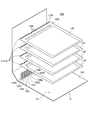
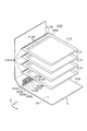
- FIG. 1 is a perspective view showing a schematic configuration of an information display system according to the first embodiment of the present invention.
- FIG. 2 is an exploded perspective view of the information display system according to the first embodiment of the present invention.
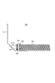
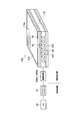
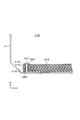
- FIG. 3 is a sectional view of the information display system according to the first embodiment of the present invention.
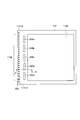
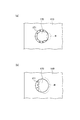
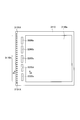
- FIG. 4 is a plan view for explaining the information display of the information display system according to the first embodiment of the present invention.
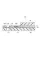
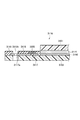
- FIG. 5 is a cross-sectional view taken along the line AA of the information display shown in FIG.
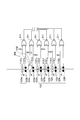
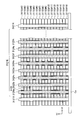
- FIG. 6 is a partially enlarged view in which the circuit configuration of the determination circuit of the information display device according to the first embodiment is partially enlarged.
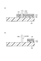
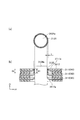
- 7A and 7B are sectional views of the information display device according to the first embodiment of the present invention.
- FIG. 1 is a perspective view showing a schematic configuration of an information display system according to the first embodiment of the present invention.
- FIG. 2 is an exploded perspective view of the information display system according to the first embodiment of the present invention
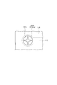
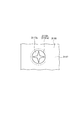
- FIG. 8 is an enlarged view of the hole of the information display device according to the first embodiment.
- FIG. 9 is a circuit diagram illustrating a determination circuit configuration of the identification signal receiving unit of the information display device according to the first embodiment.
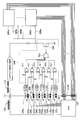
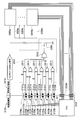
- FIG. 10 is a diagram illustrating a drive circuit arranged in the information display device according to the first embodiment and connection lines connected to the drive circuit.
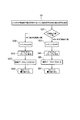
- FIG. 11 is a flowchart illustrating a process in which the control device according to the first embodiment displays information on a predetermined information display among a plurality of information displays.
- FIG. 12 is a diagram illustrating a modification of the control device side coupling mechanism.
- FIG. 13 is a diagram illustrating a modification of the control device side coupling mechanism.
- FIG. 14 is a diagram illustrating a modification of the control device side coupling mechanism.
- FIG. 15 is a diagram illustrating a modification of the structure for conducting electricity in the control device side coupling mechanism.
- 16 is a cross-sectional view taken along the line DD of FIG.
- FIG. 17A is a plan view illustrating a hole corresponding to the modification shown in FIGS. 15 and 16
- FIG. 17B is a plan view illustrating a modification of the hole.
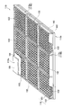
- FIG. 18 is a schematic perspective view for explaining an example of an information display applicable to the information display system according to the present embodiment.
- FIG. 19 is a functional block configuration diagram of the information display system.
- FIG. 20 is an exploded perspective view showing a part of a particle movement type information display which is an example of an information display applicable to the information display system.
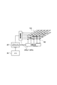
- FIG. 21 is a schematic diagram illustrating an example of an information processing system according to the second embodiment.
- FIG. 22 is a diagram illustrating a configuration of a control device that realizes a process of displaying information on a plurality of information displays in the second embodiment.
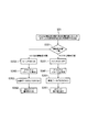
- FIG. 23 is a flowchart for describing processing for displaying information for 12 pages on an information display system including five information displays A to E in the second embodiment.
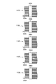
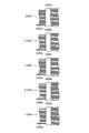
- 24A to 24C are diagrams for explaining the tables T1, T2, T3 created in the method 1.
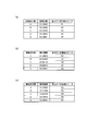
- FIGS. 25A to 25C are diagrams illustrating the tables T1, T2, and T3 created in the method 2.
- FIG. FIG. 26 is a perspective view showing a schematic configuration of an information display system according to the third embodiment of the present invention.
- FIG. 27 is an exploded perspective view of an information display system according to the third embodiment of the present invention.
- FIG. 28 is a sectional view taken along line XX of the information display system shown in FIG. 29 is a cross-sectional view taken along line YY of the information display system shown in FIG.
- FIG. 30A is a plan view of the conductive connection portion 124 formed in the protruding portion which is the device side coupling mechanism of the control device.
- FIG. 30B is an enlarged cross-sectional view of a connection portion of the information display system.
- FIG. 31 is a plan view for explaining an information display of the information display system according to the embodiment of the present invention.
- 32 is a cross-sectional view taken along line AA of the information display shown in FIG. FIG.
- FIG. 33 is an enlarged view of a hole serving as a conductive connection portion of the information display device according to the third embodiment of the present invention.
- FIG. 34 is a circuit diagram illustrating an example of a connection configuration and a determination circuit between a control device and an information display according to the third embodiment of the present invention.
- FIG. 35 is a diagram for explaining a drive circuit arranged in the information display device according to the third embodiment of the present invention and a connection line connected to the drive circuit.
- FIG. 36 is a flowchart for explaining processing of the information display system.
- FIG. 37A is a diagram for explaining an information display system according to a modification of the device-side coupling mechanism.
- FIG. 37B is a diagram illustrating an information display system according to another modification of the device-side coupling mechanism.
- FIG. 37A is a diagram for explaining an information display system according to a modification of the device-side coupling mechanism.
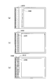
- FIG. 39A is a diagram for explaining another embodiment of the information display device according to the third embodiment.
- FIG. 39B is a diagram for explaining another embodiment of the information display device according to the third embodiment.
- FIG. 39C is a diagram for explaining another embodiment of the information display device according to the third embodiment.
- the determination circuit provided in the information display device is based on the arrangement pattern of the conductive portion and the insulating portion and the control signal received by the control signal receiving unit. Decide whether to rewrite display information on the display or not. For this reason, the control device can perform a process of displaying information on the specified predetermined information display device based on the arrangement pattern of the conductive portion and the insulating portion and the control signal transmitted by the control device.
- the control signal is transmitted toward the drive circuit of all the information displays connected with a control apparatus, and the information display which was to rewrite display information Can only be rewritten.
- the electrical connection part of a control apparatus and a some information indicator can be shared. Therefore, it is possible to form a booklet having a structure in which a plurality of information displays are bound by providing an electrical connection portion in a coupling mechanism that connects one control device and a plurality of information displays. Details will be described below.
- FIG. 1 is a perspective view showing a schematic configuration of the information display system 100.
- FIG. 2 is an exploded perspective view of the information display system 100.
- FIG. 3 is a cross-sectional view of the information display system 100.
- the information display system 100 includes a plurality of information displays 110 and a control device 120 that controls display of information on the plurality of information displays 110.
- the control device 120 constitutes the exterior body C.
- the control device 120 includes a CPU 20, a graphic controller 30, a memory, and the like, and controls display of information on the information display 110.
- the control device 120 is formed with a plurality of protrusions 121 protruding from the exterior body C, and the plurality of information displays 110 are formed with holes (through holes) 110h. Has been.
- the information display device 110 is attached to the control device 120 by the protrusion 121 passing through the hole 110h.
- the plurality of information displays 110 are spelled into the control device 120 in a booklet form.
- the control device 120 may be provided with a connection terminal (not shown) that can be connected to a personal computer (PC), other electronic devices, a storage device, and the like.
- the power supply required when executing information display is such that a power source such as a sheet battery or a coin-type battery is mounted on the exterior body C and connected to the control device 120, or the control device 120 provided on the exterior body C This can be done by connecting an external power supply to the connected connection terminal.
- a power source such as a sheet battery or a coin-type battery
- FIG. 1 shows a configuration in which the control device 120 is provided in the outer package C of the information display device bound in a booklet shape
- the control device 120 is separated from the information display device bound in a booklet shape.
- the information display system may be configured to display information by connecting to a connection terminal provided on the exterior body C.
- the protrusion 121 and the hole 110 h are engaged with each other to mechanically connect the information display 110 and the control device 120 and to electrically connect the information display 110 and the control device 120.
- the control device 120 spells a plurality of information displays 110 together and is electrically connected to the information display 110. That is, the protrusion 121 provided with the conductive member and the hole (through hole) 110h provided with the conductive member are portions where the information display 110 and the control device 120 are physically and mechanically connected. It is a part which is electrically connected.
- the projecting portion 121 that does not include a conductive member and the hole portion (through hole) 110 h that does not include a conductive member are a portion that connects the information display 110 and the control device 120 exclusively physically and mechanically.
- the protrusion 121 constitutes a control device side coupling mechanism
- the hole 110h constitutes an information display side coupling mechanism.
- the information display system 100 shown in FIG. 1 includes a fastener 130 having at least a surface formed of an insulating material.
- the information display 110 stacked by inserting the hole portion 110h into the protruding portion 121 is fixed by the insulating fastener 130 in a state where the protruding portions 121 in which the conductive portions are formed do not leak.
- FIG. 4 is a plan view for explaining the information display 110.
- the information display device 110 is a rectangular thin panel type, and can be used as electronic paper or the like.
- the rectangular shape referred to here is a shape generally known for notebook paper or the like, and includes a case where corners are cut round or a corner is cut slightly linearly.
- an information display area 110a for displaying information is formed.
- FIG. 5 is a cross-sectional view taken along line AA of the information display 110 shown in FIG.
- the information display 110 includes a pair of substrates (observation side substrate 181 and back side substrate 182).
- the observation side substrate 181 is transparent.
- the information display area 110a is formed on the observation side substrate 181.
- An observation side electrode (not shown in FIGS. 4 and 5) is formed on the observation side substrate 181.
- a back side electrode 192 is formed on the back side substrate 182.
- a predetermined gap (gap) is formed between a pair of substrates on which a pair of display electrodes (observation side electrode, back side electrode) is formed, and between the observation side electrode and the back side electrode,
- a display medium layer 115 is disposed.
- each information display device is aligned, that is, the display screen of each information display device is shown as being overlapped, but the back side of the two information display devices are bonded together, It is good also as an information indicator provided with a display screen on both sides. Also in this case, in the two information displays bonded together, the arrangement pattern of the insulating portion and the conductive portion determined by the arrangement position and the number of arrangement of the notch portions 300 provided as the insulating portion, for example, is different.
- the display medium layer 115 may be a gas layer (including a vacuum layer) or a liquid layer in which particles containing charged particles are arranged as a display medium, or a cholesteric liquid crystal layer. Both have display memory properties and can hold displayed information (images) even in a non-powered state.
- the display medium is at least two types of particle groups having charging characteristics and optical reflectance, for example, negatively charged white particles or positively charged black particles. These chargeable particles move in gas (including vacuum) or liquid toward the observation side electrode (or back side electrode) by an electric field formed by a voltage applied between the substrates.
- the back side substrate 182 is formed wider than the information display area 110 a and forms the skeleton of the information display device 110.
- a drive circuit 200 is disposed on the back side substrate 182 via the electrode 117. The electrode 117 and the drive circuit 200 are covered with an insulating film 118. An example of the information display device 110 applicable in the embodiment will be described later.
- the information display 110 includes a plurality of drive circuits 200a to 200e on the outside of the information display area 110a in a plane.
- the drive circuits 200a to 200e are also called driver ICs, and this driver IC has a function of invalidating OUTPUT (signal output to the panel), and is provided between an observation side electrode and a back side electrode, which will be described later.
- By controlling the voltage to be applied desired information is displayed in the information display area 110a.
- Cutout portions (insulating portions) 300 are formed at some positions of the hole 110 h outside the information display area 110 a so as to correspond to the page numbers of the information display 110.
- a control signal is transmitted from the CPU 20 provided on the control device side to the drive circuits provided in each of the plurality of information displays.
- the control signal includes an identification signal transmitted to a determination circuit described later and a drawing data signal including drawing data to be displayed on the information display 110.
- the plurality of protrusions 121 of the control device are engaged with the identification signal transmission units 123b, 123d, 123f, 123h, 123j, and 123l, the conduction connection units 124a, 124c, 124e, 124g, 124i, and 124k. Part 123X.
- the identification signal transmission units 123b, 123d, 123f, 123h, 123j, and 123l transmit the identification signal included in the control signal from the CPU 20 to all the information displays 110.
- Each information display 110 determines whether the transmitted identification signal is a control signal (drawing data signal) displayed by itself or a control signal (drawing data signal) that is not displayed by the determination circuit 310. This determination method will be described later in detail with reference to FIG.
- the conductive connection portions 124a, 124c, 124e, 124g, 124i, and 124k are electrically connected to a conductive connection portion, which will be described later, of the information display 110.
- the engaging portion 123X is inserted into a hole (through hole) 110h of the information display device 110 and has a function of bundling a plurality of information display devices 110.
- the projecting portions 121 at both ends are configured as engaging portions 123X, but the engaging portion 123X may be configured by another projecting portion 121. It may be one, or three or more.
- the protrusion part 121 does not need to be provided with the engaging part 123X.
- the plurality of hole portions (through holes) 110h of the information display device 110 include a conductive member and a conductive portion, and do not include a conductive member. And a hole.
- the holes constituting the conducting portions are identification signal receivers 1131b, 1131d, 1131f, 1131h, and 1131j that receive the identification signals corresponding to the identification signal transmitters 123b, 123d, 123f, 123h, 123j, and 123l of the protrusion 121.
- the hole portion that does not constitute the conduction portion is an engagement hole portion (through hole) 1131X for physically and mechanically connecting the control device and the information display 110 by inserting the engagement portion 123X of the control device. .
- the engagement hole portion 1131X is a hole portion used only for mechanical engagement, and can be a hole portion not provided with a conductive member, but of course, a hole portion provided with a conductive member. You can also.
- the engaging portion 123X is a protruding portion used only for mechanical engagement, and can be a protruding portion that does not include a conductive member, but of course, it can also be a protruding portion that includes a conductive member. .
- the hole portions at both ends corresponding to the engagement portion among the plurality of hole portions 110h are configured as the engagement hole portion 1131X, but the engagement hole portion 1131X is formed of a conductive member. You may comprise by another hole part provided, may be comprised by the hole part which is not provided with an electroconductive member, may be one, and may be three or more. Further, the information display 110 may not include the engagement hole portion 1131X.
- FIG. 6 shows identification signal receivers 1131b, 1131d, 1131f, 1131h, 1131j, and 1131l of the information display 110, and conductive connection parts 1131a and 1131c (not shown, insulating part 1132 (not shown) which are conductive parts other than the identification signal receiver. It is shown as a notch 300).
- FIG. 13B is a partially enlarged view showing the configuration of a determination circuit included in 1131e, 1131g, 1131i, 1131k and an information display.
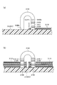
- FIG. 7A is a partial cross-sectional view of the information display device in a cross section passing through the identification signal transmitting unit 123h and the identification signal receiving unit 1131h
- FIG. 7B is a conductive connection unit 124c and an insulating portion 1132 (notched portion).
- 300) is a partial cross-sectional view of the information display in a cross section passing through 300).
- the conductive connection portions 1131a, 1131c, 1131e, 1131g, 1131i, and 1131k (in the drawing, except for the identification signal receiving portions 1131b, 1131d, 1131f, 1131h, 1131j, and 1131l (indicated by the mark ⁇ ).
- An insulating portion is formed in a portion marked with a circle.
- an insulating portion 1132 is formed as a notch portion 300 at a portion 1131c which is a conductive portion.
- the identification signal receiving units 1131b, 1131d, 1131f, 1131h, 1131j, 1131l and the conductive connection units 1131a, 1131c, 1131e, 1131g, 1131i, 1131k are arranged adjacent to each other to form a determination circuit.
- the arrangement pattern of the insulating portion and the conductive portion determined by the arrangement position and the number of arrangement of the notch portions 300 provided as the insulating portion, for each information display Different.
- the conductive connection portion 124 c of the protruding portion 121 including a conductive member is not electrically connected to the information display 110 at the cutout portion 300. That is, the notch 300 constitutes an insulating portion 1132.
- the conductive portions constituting the determination circuit of the information display 110 are the identification signal receiving units 1131b, 1131d, 1131f, 1131h, 1131j, and 1131l, and the conductive connection units 1131a, 1131c, 1131e, and 1131g. 1131i and 1131k. At least one insulating portion 1132 (for example, the notch portion 300) is provided in the conductive connection portions 1131a, 1131c, 1131e, 1131g, 1131i, and 1131k.
- the identification signal receivers 1131b, 1131d, 1131f, 1131h, 1131j, and 1131l are electrically connected to the identification signal transmitters 123b, 123d, 123f, 123h, 123j, and 123l of the control device 120 that transmits the identification signal.
- the conductive connection portions 1131a, 1131c, 1131e, 1131g, 1131i, and 1131k are electrically connected to the conductive connection portions 124a, 124c, 124e, 124g, 124i, and 124k of the control device 120. Since the portion 1131 c is an insulating portion 1132, it is electrically insulated from the conductive connection portion 124 c of the control device 120.
- the insulating portion 1132 in FIG. 6 is shown as a notch, it may be a hole (through hole) instead of a notch.
- the conductive member is not exposed at least inside the hole.
- the hole diameter is larger than the diameter of the conduction
- the hole diameter of the through hole is a through hole in which the conductive connection portions 1131a, 1131b, 1131d, 1131e, 1131f, 1131g, 1131h, 1131i, 1131j, 1131k, 1131l are formed. It is larger than the hole diameter of the hole.
- the insulating portion 1132 is a notch 300 in which the through hole is not circular but is cut into a rectangle having an area larger than the area of the through hole.
- the hole portion 110h formed by increasing the hole diameter in the hole portion 110h that becomes the conductive connection portion 1131c does not come into contact with the conductive connection portion 124c, and thus becomes an insulating portion 1132 that is electrically insulated.
- FIG. 6 shows an example in which the notch portion 300 is provided to form the insulating portion 1132.
- the conductive connection portions 1131a, 1131c, 1131e, 1131g, 1131i, and 1131k extend to the logic circuit side.
- the insulating portion 1132 may be formed by disconnecting the wiring.
- the hole 110h serving as the insulating portion 1132 can also be provided in the same manner as the hole 110h serving as the other conductive connection portions 1131a, 1131c, 1131e, 1131g, 1131i, and 1131k.
- FIG. 8 is an enlarged view of the hole 110h (hole in which the conductive connection portion 1131a is formed) provided with a conductive member in a plan view of the information display device 110.
- the hole 110h formed on the back side of the information display 110 (here, the back side substrate 182) is penetrated.
- the electrode 117 has an exposed portion 117a.
- the exposed portion 117a protrudes toward the center of the hole portion 110h and is exposed.
- the exposed portion 117a comes into contact with a protruding portion (121 in FIG. 2) provided with a conductive member, so that the information display device 110 and the control device 120 can be electrically connected.
- the hole 110 h is provided in the back side substrate of the information display.
- the hole 110 h may be a tape carrier package (TCP) or a flexible circuit board (FPC) mounted on one side of the information display. ).
- TCP tape carrier package
- FPC flexible circuit board
- FIG. 9 is a circuit diagram illustrating the circuit configuration of the determination circuit provided in the identification signal receiving units 1131b, 1131d, 1131f, 1131h, 1131j, and 1131l of the information display device 110 according to the embodiment. is there.
- FIG. 9 shows a part of the CPU 20 that transmits a control signal including an identification signal, the insulating portion 1132 shown as the notch 300, and the vicinity of the conductive portion on the control device 120 side and the information display 110 side.
- FIG. 10 is a diagram illustrating the drive circuits 200a to 200e disposed in the information display device 110 according to the embodiment and the connection lines connected to the drive circuits 200a to 200e.
- the identification signal receivers 1131b, 1131d, 1131f, 1131h, 1131j, and 1131l are electrically connected to the identification signal transmitters 123b, 123d, 123f, 123h, 123j, and 123l among the protrusions 121 that include the conductive member of the control device 120.
- Conductive connection portions 1131a, 1131c illustrated as notch portions 300 in FIG. 9) other than the identification signal receiving portion, 1131e, 1131g, 1131i, 1131k are conductive connection portions 124a, 124c, 124e, 124g, 124i, 124k of the control device 120. And electrically connected.
- At least one of the conductive connection portions 1131a, 1131c, 1131e, 1131g, 1131h, and 1131k is provided with an insulating portion 1132 (for example, the notch portion 300) that is not electrically connected to the control device 120 side.
- the insulating portion 1132 is cut out in the portion that becomes the conductive connection portion 1131c in the other information display of the information display 110 shown in the drawing.
- an arrangement pattern of one insulating portion and five conductive connection portions is formed and used as identification information of the information display.
- the information display device 110 having a configuration in which six conductive connection portions other than the identification signal receiving portion as shown in FIG. 6 are provided in the determination circuit one to six insulating portions can be provided. 1] Various arrangement patterns can be obtained.
- one insulating display part may be provided in one information display device 110, or a plurality of insulating parts may be provided.
- one information display device among the plurality of information display devices provided in the information display system may not be provided with an insulating portion. In other words, in an information display system in which a plurality of information displays are connected to the control device, it is only necessary that the arrangement patterns of the insulating portions are different from each other.
- the identification signal receiving units 1131b, 1131d, 1131f, 1131h, 1131j, 1131l, the conductive connection units 1131a, 1131e, 1131g, 1131i, 1131k, and the insulating portion 1132 are formed as shown in FIG.
- a determination circuit 310 including a NAND circuit 312 as a logic circuit is configured, and the identification signal received via the identification signal receivers 1131b, 1131d, 1131f, 1131h, 1131j, and 1131l, and an insulating portion in the information display Comparing the identification information determined by the arrangement pattern of the (insulating part formed in the conductive connection part) and the arrangement pattern of the conductive part (conductive part formed in the conductive connection part) to determine whether they match or not, Depending on the determination result, the drive circuits 200a-2 provided in the information display It is configured to be electrically connected to the driving circuits 200a ⁇ 200e so that it can be enabled or disabled the output enable (OUTPUT-ENABLE) of 0e.
- the circuit wiring different from the example shown in FIG. 9 can be connected to the chip select lines 320a to 320e of the drive circuits 200a to 200e.
- the circuit wiring constituting the determination circuit is shown in FIG. It is not limited to the example shown.
- the determination circuit needs identification information for specifying the information display.
- an arrangement pattern determined by the number and positions of insulating portions 1132 (notches 300) formed in the determination circuit is formed as the identification information.
- the identification number transmitted with the drawing data from the control device, and the page number stored in the memory, provided with an IC chip (memory) that stores information specifying the information display, for example, the page number, is not limited thereto It is also possible to make a configuration that compares information with each other to determine whether it matches or does not match.
- the information display device including the insulating portion 1132 (for example, the notch 300) has a simpler circuit configuration than the information display device including the IC chip memory, and the expensive IC. There is an advantage that it can be made inexpensive by not requiring a chip.
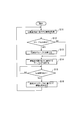
- FIG. 11 is a flowchart illustrating a process in which the control device 120 displays information on the plurality of information displays 110.
- a control signal drawn data signal
- the control signal including an identification signal for identifying the drawing data signal to be displayed on the second page is transmitted from the CPU 20 of the control device, and the second page is based on the drawing data signal. Display an image.
- step 1 the control device 120 transmits a control signal to the information display 110. Specifically, a drawing data signal for displaying desired information in the information display area 110a is transmitted to the information display 110 via the drawing data signal transmission unit 122, and the identification signal transmission units 123b, 123d, An identification signal for identifying the information display 110 in the determination circuit is transmitted to the information display 110 through 123f, 123h, 123j, and 123l.
- the drawing data signal from the drawing data signal transmission unit 122 is received by the drawing data signal receiving unit 1120 of the information display 110 and input to the drive circuits 200a to 200e.
- the identification signal and the drawing data signal are transmitted to all the information displays 110.
- the # 2 information display unit receives the identification signals received by the identification signal receiving units 1131b, 1131d, 1131f, 1131h, 1131j, and 1131l, the insulating portion 1132 (the notch portion 300), and the conductive connection portions 1131a, 1131e, and 1131g.
- the identification information determined by the arrangement patterns 1131h and 1131k is compared to determine whether they match or do not match.
- the identification signal to be displayed on the second page from the identification signal transmission units 123b, 123d, 123f, 123h, 123j, 123l of the control device 120 to the determination circuit on the information display device 110 side (for example, “010000”). ) Is transmitted to all 64 information displays 110.
- the outputs of the identification signal receivers 1131b, 1131f, 1131h, 1131j, and 1131l are “0”.
- the output of the identification signal receiving unit 1131d is “1”.
- the outputs of the conductive connection portions 1131a, 1131e, 1311, g, 1311, i, and 1311k are grounded via the conductive connection portions 124a, 124e, 124g, 124i, and 124k, and become “0”.
- the portion where the notch 300 is formed is not grounded, “1” is output. Therefore, in the # 2 information display 110, the truth value on the output side of the XNOR circuit 311 of the determination circuit 310 is “111111”.
- the outputs of all the XNOR circuits 311 are “1”, and the outputs of the NAND circuits 312 are “0”. That is, in the # 2 information display device, the identification information of the # 2 information display device matches the received identification signal (step 21: YES).
- the switch 350 is turned off (OFF) (step 31), the output enable (OUTPUT-ENABLE) of the drive circuits 200a to 200e is enabled (step 41), and the output signal from the CPU is received.
- Drawing data is output from the drive circuits 200a to 200e to the information display area 110a of the information display (step 51). Therefore, the # 2 information display is rewritten (step 61).
- Step 1 when the control device 120 transmits a control signal (drawing data displayed on the second page and an identification signal for identifying the second page) to the # 1 information display, the # 1 information display
- the # 1 information display The identification signals received by the identification signal receiving units 1131b, 1131d, 1131f, 1131h, 1131j, and 1131l, and the arrangement pattern of the insulating portions 1132 (notched portions 300) and the conductive connection portions 1131a, 1131e, 1131g, 1131h, and 1131k
- the determined identification information is compared to determine whether or not they match.
- the outputs of the identification signal receivers 1131b, 1131f, 1131h, 1131j, 1131l are “0”.
- the output of the identification signal receiving unit 1131d is “1”.
- the outputs of the conductive connection portions 1131c, 1131e, 1311, g, 1311, i, and 1311k are grounded via the conductive connection portions 124c, 124e, 124g, 124i, and 124k, and become “0”.
- the portion where the notch 300 is formed is not grounded, “1” is output. Therefore, in the # 1 information display 110, the truth value on the output side of the XNOR circuit 311 of the determination circuit 310 is “001111”.
- step 21: NO Since the outputs of all the XNOR circuits 311 are not “1”, the output of the NAND circuit 312 is “1”. That is, in the # 1 information display, the identification information of the # 1 information display and the received identification signal do not match (step 21: NO).
- the switch 350 is turned on (step 32), the output enable (OUTPUT-ENABLE) of the drive circuits 200a to 200e is invalidated (step 42), and the output signal from the CPU is received.
- Drawing data is not output from the drive circuits 200a to 200e to the information display area 110a of the information display (step 52). Therefore, rewriting of the # 1 information display (similar to other information displays other than the # 2 information display) is not executed (step 62).
- the # 1 information display corresponding to the first page is described as an example.
- the # 3 information display corresponding to the third page, the # 4 information display corresponding to the fourth page, and the # 5 information corresponding to the fifth page are described.
- the input identification signal and the arrangement pattern of the notch 300 do not match, as in the # 1 information display 110. , Rewriting is not performed.
- the information display device 110 includes a determination circuit 310 that compares the identification information determined by the arrangement patterns 1131h and 1131k to determine whether the identification information matches or does not match.
- Drawing data is output from the drive circuits 200a to 200e to the information display area 110a.
- the configuration of the determination circuit shown in the embodiment of the present invention is an example.
- the XNOR logic circuit compares the insulation portion (notch portion) and the input from each terminal of the CPU, but for example, a method of receiving the input from the CPU terminal once by the shift register is also conceivable.
- the information given as the arrangement pattern of the insulating portion (notch portion) and the information by the identification signal transmitted from the control device are compared, and a circuit for detecting whether or not they match is determined.
- the logic circuit (XNOR, NAND) described in the embodiment of the present invention and may be a commonly used electronic circuit such as another logic circuit or a memory circuit.
- the present invention is characterized in that the information display system of the present invention is configured by using an information display in which a determination circuit is configured by combining an arrangement pattern of insulating portions (notches) and an electronic circuit.
- the plurality of projecting portions 121 formed in the control device 120 constitutes a control device side connection mechanism.
- some of the protrusions 121 having conductive members among the protrusions 121 constitute a control signal transmission unit that transmits a control signal for controlling the drive circuits 200a to 200e.
- Some of the control signal transmission units constitute an identification signal transmission unit 123 that transmits an identification signal included in the control signal (a signal transmitted to identify the information display 110), and some of the other control signal transmission units.
- Some of the protrusions 121 can be used for merely making a mechanical connection without making an electrical connection. This protrusion does not need to be provided with a conductive member.
- a hole (through hole) 110h that constitutes the determination circuit 310 formed in the information display 110 and includes a conductive member used for electrical connection is an identification signal receiver connected to the identification signal transmitter And a conductive connection portion.
- the identification signal receiving portion and the conductive connection portion are arranged in pairs, and the insulating portion 1132 (for example, the notch portion 300) is formed in this conductive connection portion.
- One or a plurality of insulating portions 1132 provided in the conductive connection portion may be provided, and a plurality of arrangement patterns are formed by a combination of the arrangement number and the arrangement position.
- FIG. 9 shows an example in which one insulating portion is formed in the conductive connecting portion formed in the conductive connecting portion. However, a plurality of insulating portions (for example, six XNOR circuits are provided as shown in FIG. 9). 6 (in the determination circuit configuration), as shown in FIG. 9, at least an insulating portion formed in the conductive connection portion, and 63 (26-1) arrangement patterns of the conductive portion and the insulating portion are different.
- the identification signal received by the identification signal receivers 1131b, 1131d, 1131f, 1131h, 1131j, and 1131l, the insulating portion 1132 (the notch portion 300), the conductive connection portions 1131a, 1131e, 1131g, 1131h, and 1131k are compared with the identification information determined by the arrangement pattern, and it is determined whether or not they match, and the drive circuits 200a to 200e are only applied to the information display 110 where the identification signal and the identification information match.
- the output enable is enabled, and output based on the control signal (drawing data signal) becomes possible. And only the information display device in which this identification signal and this identification information correspond can display predetermined information (image) based on the control signal (drawing data signal) including this identification signal.
- predetermined information is displayed on the information display 110 that matches the identification signal transmitted from the control device 120.
- the information display system 100 does not depend on whether or not the plurality of information displays 110 constituting the “page” are in a spread state, that is, the booklet-shaped information display system 100 keeps the booklet closed and the predetermined information Predetermined information (image) can be displayed on the display device 110.
- the control device 120 transmits an identification signal to the determination circuits of all the linked information displays 110, and identifies the identification signal and the number of the information display.
- the output enable is valid only for the drive circuits 200a to 200e included in the information display 110 that matches the identification information.
- the identification information for identifying the number of the information display includes the arrangement position of the insulating part (notch part), the number of arrangements of the insulating part (notch part), and other conductive parts in the conductive part other than the identification signal receiving part. Is determined as a placement pattern determined by the combination of the control signal 120 and the logic circuit that constitutes the determination circuit is used to determine whether the identification signal matches or does not match, and when it matches, the switch 350 is turned off.
- the output enable of the drive circuits 200a to 200e is made effective with respect to the control signal from.
- the control device 120 it is possible to share an electrical connection with a plurality of information displays 110.
- the information indicator 110 can be made into a booklet shape by inserting the holes 110 h formed in the plurality of information indicators 110 into the protruding portion 121 of the control device 120.
- the information display 110 is flexible along the connection mechanism to view the information displayed on each information display as if turning the page.
- the information displayed on each information display can be viewed by turning the page without bending the information display 110 along the connecting mechanism. .
- FIG. 12 and 13 are diagrams for explaining a modification of the control device side coupling mechanism.
- the bending member 140 is attached to the exterior body C instead of providing the fastener 130.
- One end portion 140 a of the bending member 140 is attached to the exterior body C.
- the other end portion 140 b of the bending member 140 is in contact with an unfixed end portion 121 f of the protruding portion 121. That is, a closed annular structure is formed by the bending member 140 and the protruding portion 121.
- the bending member 140 is configured to be movable in a direction in which the end portion 140b and the end portion 121f of the projecting portion 121 are separated from each other, and the information display device 110 inserted through the projecting portion 121 includes a ring (projecting from the bending member 140 and the projecting portion 121). The ring structure closed by the part 121).
- the bending member 140 can be formed of a conductive material. As a result, the information display 110 is moved from the right side to the left side in FIG. 13 and the information display unit 110 located on the left side (that is, not viewed by the user) displays information. be able to.
- FIG. 14 is a diagram illustrating another modification of the control device side coupling mechanism. As shown in FIG. 14, one end portion 140 a of the bending member 140 is attached to the exterior body C via the rotation mechanism 150. The bending member 140 is rotated in the direction of the arrow in FIG. 14 by the rotation mechanism 150, whereby the end portion 140b and the end portion 121f are separated from each other.
- FIG. 15 is a diagram illustrating a modification of the structure for conducting electricity of the coupling mechanism in the control device side coupling mechanism.
- 16 is a cross-sectional view taken along the line DD shown in FIG.
- FIG. 15 shows a bending member 160 having a shape similar to that of the bending member 140 shown as the first modification.
- the bending member 160 is formed of an insulating material, and a conductive material 161 is disposed in part of the insulating material.
- the projecting portion 121 is also formed of an insulating material, and a conductive material 162 is disposed on a part of the projecting portion 121.
- the conductive materials 161 and 162 are disposed on a part of the inside of the annular structure formed by the bending member 160 and the protruding portion 121.
- a region R surrounded by a dotted line indicates a portion where the electrode is not exposed.
- the exposed electrode 171 is formed at a position corresponding to the conductive materials 161 and 162 disposed on the insulating protrusion 121 and the insulating bending member 160 shown in FIG.
- a process of displaying information on the information display 110 is performed by configuring a conductive structure in which the main part of the protrusion 121 on the control device side in the coupling mechanism is insulative and partly conductive. Even if the user touches adjacent protrusions 121 (or the bending members 140 shown as the first and second modifications 1 and 2) at the same time, the short circuit can be prevented and the process of displaying information is ensured. Can be executed.
- FIG. 18 is a schematic perspective view for explaining the configuration outline of the information display system 100 according to the present embodiment and the information display 110 applicable thereto.
- the information display device 110 includes a pair of electrodes (observation side electrode 191 and back side electrode 192) and a pair of substrates (observation side substrate 181 and back side substrate 182). Between the pair of substrates, a gap securing partition wall 119a and a particle uneven distribution suppressing partition wall 119b (both are not shown in FIG. 18. In FIG. 20, a partition serving as both a gap securing partition wall and a particle uneven distribution suppressing partition wall. Is shown).
- the information display device 110 includes a display medium layer 115 in which a display medium 116 having a display memory property that is electrically driven through electrodes is arranged.
- the information display device 110 further includes drive circuits 200a to 200e, and the information display area 110a of the information display device 110 has a desired display based on control by the drive circuits 200a to 200e (not shown in FIG. 23, see 200 in FIG. 2). Is displayed as an image.
- the observation side substrate 181 is a substrate in which at least the information display region 110a arranged on the information display region 110a side, that is, the observed side is transparent.
- the back side substrate 182 faces the observation side substrate 181 and is provided on the back side 110 b side of the information display 110.
- the observation side substrate 181 and the back side substrate 182 are provided outside the pair of electrodes (the observation side electrode 191 and the back side electrode 192).
- the thickness of the observation side substrate 181 and the back side substrate 182 is preferably 25 ⁇ m to 2,000 ⁇ m, more preferably 25 ⁇ m to 500 ⁇ m, and still more preferably 25 ⁇ m to 200 ⁇ m.
- plastic materials such as polyethylene terephthalate (PET), polyethylene naphthalate (PEN), polyethersulfone (PES), polyethylene, polycarbonate, polyimide, acrylic resin, and glass , Quartz, hard plastic, glass fiber reinforced plastic, carbon fiber reinforced and the like.
- the plastic materials described above including polyethylene terephthalate and polyethylene naphthalate, are flexible, when the information display device 110 is to be flexible, the materials for forming the observation side substrate 181 and the back side substrate 182 are used. preferable.
- the observation side substrate 181 and the back side substrate 182 are desired to be as thin as possible in order to make the entire information display system lightweight and thin. Considering this point, each thickness is set to 25 ⁇ m or more.
- the information display device 110 when glass is used as a material for forming the observation side substrate 181 and the back side substrate 182, if the thickness is 200 ⁇ m or less, the information display device 110 is flexible. Is preferred. Furthermore, since metal materials such as aluminum, copper, nickel, alloys thereof, and stainless steel are also flexible, the observation side substrate 181 and the back side substrate are used when the information display 110 is flexible. Although it can be used as a material of 182, it is necessary to cover the surface with an insulator film or sheet in order to prevent leakage between electrodes formed on the substrate.
- a non-transparent material can be selected and used from the materials described above.
- the observation side electrode 191 is a transparent electrode arranged on the information display area 110a side, that is, on the side to be observed.
- the back side electrode 192 faces the observation side electrode 191 and is provided on the back side 110 b side of the information display 110.
- the back side electrode 192 is not necessarily transparent.
- the conductive materials constituting the observation side electrode 191 and the back side electrode 192 include (i) indium tin oxide (ITO), indium oxide, zinc doped indium oxide (IZO), aluminum doped zinc oxide (AZO), antimony tin oxide.
- conductive metal oxides such as conductive tin oxide and conductive zinc oxide
- polymer compounds such as polyaniline, polypyrrole, and polythiophene (for example, PEDOT: PSS)
- metals such as gold, silver, copper, aluminum, nickel, chromium, and
- alloys containing these metals as main components
- a method for forming the observation side electrode 191 and the back side electrode 192 a method of forming the above-described conductive material into a thin film by sputtering, vacuum deposition, CVD (chemical vapor deposition), coating, or the like, metal foil ( For example, a method of laminating a rolled copper foil) and a method of applying a conductive agent mixed with a solvent or a synthetic resin binder can be used.
- the thicknesses of the observation side electrode 191 and the back side electrode 192 are only required to ensure conductivity, and are preferably 0.01 ⁇ m to 10 ⁇ m, more preferably 0.05 ⁇ m to 5 ⁇ m.
- the observation-side electrode 191 and the back-side electrode 192 are configured using these metal oxide-based conductive materials. In order to prevent disconnection, it is preferable to use in combination with fine metal wires such as copper, aluminum, nickel, and alloys thereof having excellent flexibility.
- a resist material can be used as a material for forming the gap securing partition wall 119a, and examples thereof include dry film resist materials such as Alfo NIT2 (manufactured by Nichigo Morton) and PDF300 (manufactured by Nippon Steel Chemical Co., Ltd.).
- the gap securing partition walls 119a are formed, for example, by laminating a dry film resist material on one substrate and then forming a lattice-shaped or honeycomb-shaped partition wall using a photolithography technique. Are bonded to both of the pair of substrates.
- the gap securing partition wall 119 a is formed on the observation side substrate 181 and then joined to the back side substrate 182. Note that the gap securing partition wall 119 a may be formed on the back side substrate 182 and then bonded to the observation side substrate 181.
- the gap securing partition wall 119a a sheet member having a thickness corresponding to the gap and having a recess for housing the display medium 116 or a sheet member having a hole penetrating the sheet is used. You can also. In this case, after the sheet is disposed so as to be sandwiched between the pair of substrates, the gap securing partition wall 119a is formed by bonding both surfaces of the sheet and the respective substrates.
- the display medium 116 is disposed between the observation side electrode 191 and the back side electrode 192, and is preferably sealed.
- the display medium 116 is electrically driven between the observation side electrode 191 and the back side electrode 192 via the electrodes.
- the display medium 116 is composed of a particle group including negatively charged white particles and a particle group including positively charged black particles, that is, particle groups having two types of charging polarity and optical reflectance.
- the display medium 116 moves to the opposite substrate side (electrode side) by an electric field formed through the electrodes. Details of the display medium 116 will be described later.
- FIG. 19 is a functional block configuration diagram of the information display system 100.
- the information display device 110 includes drive circuits 200a to 200e that have at least a function of disabling output and a function of driving the information display unit.
- the CPU 20 and the graphic controller 30 of the control device are connected.
- FIG. 20 is a partially exploded perspective view of the information display device 110.
- the gap securing partition wall 119 a forms a plurality of cells 132.
- a display medium 116 is disposed, preferably encapsulated.
- the gap securing partition wall 119a is disposed between the observation-side electrode 191 and the back-side electrode 192.
- the observation-side substrate 181 is provided on the outside of the space formed between the observation-side electrode 191 and the back-side electrode 192 provided separately, that is, on the information display area 110a side and the back surface 110b side of the gap securing partition wall 119a.
- a back substrate 182 are provided on the outside of the space formed between the observation-side electrode 191 and the back-side electrode 192 provided separately, that is, on the information display area 110a side and the back surface 110b side of the gap securing partition wall 119a.
- a back substrate 182 are provided. Specifically, the observation side substrate 181 is provided on the information display region 110a side of the gap securing partition wall 119a, and the back side substrate 182 is provided on the back surface 110b side.
- the cell 132 shown in FIG. 20 has a substantially rectangular shape in plan view of the information display 110, and is continuously formed in the vertical and horizontal directions of the gap securing partition wall 119a.
- the cells 132 are formed in a matrix by linear gap securing partitions 119a extending in the vertical and horizontal directions.
- the cells 132 may be hexagonal and arranged in a honeycomb structure.
- the display medium 116 includes a display medium 151 and a display medium 152.
- the display medium 151 is a particle group including black positively charged particles.
- the display medium 152 is a particle group including white negatively charged particles.
- Two types of display media, the display medium 151 and the display medium 152, are arranged in each cell 132.
- the black particle group used as the display medium 151 can be manufactured as follows. (I) 60 parts by mass of methyl methacrylate monomer (Kanto Chemical Reagent) and 40 parts by mass (about 25 mol%) of ethylene glycol dimethacrylate (Wako Pure Chemical Reagent) as a polyfunctional monomer having a plurality of polymerization reactive groups in one molecule Then, 3 parts by mass of a nigrosine compound (Ponttron No7: manufactured by Orient Chemical Co., Ltd.) as a positively charged charge control agent and 5 parts by mass of carbon black (special black: manufactured by Degussa) as a black pigment are dispersed by a sand mill (acrylic and methacrylic).
- Resin) -hydrocarbon resin block copolymer (Modiva F600: made by NOF Corporation) is dissolved.
- the product of (i) is suspended in purified water with added%, polymerized, filtered and dried.
- the product of (ii) is classified using a classifier (MDS-2: Nippon Pneumatic Industrial) to obtain positively charged black particles having an average particle size of about 10 ⁇ m.
- a black particle group as a black display medium is obtained by externally adding silica fine particles (W3050VP, manufactured by Wacker) to the black particles.
- the white particle group used as the display medium 152 can be manufactured as follows. (I) 100 parts by mass of polymethylpentene polymer (TPX-R18: manufactured by Mitsui Chemicals), 100 parts by mass of titanium dioxide (Taipaque CR-90: manufactured by Ishihara Sangyo Co., Ltd.) as a colorant, and as a negatively charged charge control agent 5 parts by mass of a phenol-based condensate (Pontron E89: manufactured by Orient Chemical Co., Ltd.) is melt-kneaded with a biaxial kneader.
- TPX-R18 manufactured by Mitsui Chemicals
- a negatively charged charge control agent 5 parts by mass of a phenol-based condensate (Pontron E89: manufactured by Orient Chemical Co., Ltd.) is melt-kneaded with a biaxial kneader.
- the product of (i) is finely pulverized by a jet mill (lab jet mill IDS-LJ type: manufactured by Nippon Pneumatic Industry) and classified using a classifier (MDS-2: manufactured by Nippon Pneumatic Industry). .
- the product of (ii) is melt spheronized using a melt spheronizer (MR-10: manufactured by Nippon Pneumatic Industry) and further classified to obtain a negatively charged white having an average particle size of about 10 ⁇ m. Get particles.
- a white particle group as a white display medium is obtained by externally adding silica fine particles (H3004 manufactured by Wacker) to the white particles.
- the protruding portion 121 has a substantially cylindrical shape and has a circular cross-sectional shape, but the cross section of the protruding portion 121 may not be circular. It may be oval or square. In order to secure a contact area between the protrusion 121 and the electrode formed in the hole 110h, a circular shape is preferable.
- the insulating portion is a notch
- the insulating portion is not limited to the notch portion 300 as long as it can ensure insulation when the control device 120 and the information display 110 are physically connected.
- an insulating portion may be formed by a disconnected portion provided in the conductive wire between the drive circuits 200a to 200e.
- one surface of the information display 110 is the observation side.
- the insulating portions (for example, the cutout portions) of the two information displays to be bonded are formed with arrangement patterns (identification information) having different arrangement positions and arrangement numbers.
- one page on the front side and one page on the back side constitute two pages.
- an electrophoretic information display device of a microcapsule type that drives a group of particles containing charged particles in a transparent insulating liquid may be used.
- a type in which particles containing charged particles are driven in a colored insulating liquid may be used.
- a white display medium composed of negatively charged white particles is enclosed in a cell formed of partition walls together with a colored insulating liquid such as blue paraffin oil.
- an information display there are a type that uses spherical particles that are configured in two colors and differently charged polarities as a display medium (for example, a twisting ball system that rotates in a microcapsule) or a type that drives a cholesteric liquid crystal.
- a display medium for example, a twisting ball system that rotates in a microcapsule
- a type that drives a cholesteric liquid crystal can be used.
- the method of driving the particle group in a gas is preferable because the drive response speed is high and the display memory property is excellent.
- the drive circuit and the information display are integrated, but the drive circuit and the information display may be configured to be detachable.
- connection means for electrically and physically connecting the driving circuit and the information display in a detachable manner.
- a concave connection terminal portion is provided in one of the information display and the drive circuit, a convex connection terminal portion meshing with the concave connection terminal portion is provided, and the concave connection terminal portion and the convex connection are provided.
- a configuration in which the drive circuit and the information display are detachably connected electrically and physically by fitting with the terminal portion can be exemplified.
- a convex terminal portion is provided on one of the information display and the drive circuit, a circular hole into which the convex terminal portion can be inserted, a slit hole having a cross shape, a circular hole,
- a hole having a combination of cross-shaped slit holes, a hole having a combination of a circular hole and a three-way slit hole, a hole in which a plurality of slit holes are gathered in a star shape, and a receiving portion having a star-shaped hole can be exemplified.
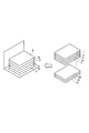
- FIG. 21 a case of an information display system in which a booklet in which five information displays are spelled as shown in FIG. 21 will be described.
- the information display system five information displays indicated by A, B, C, D, and E are prepared, and information for five pages can be displayed.
- the information acquisition unit 2211 acquires information to be displayed on the information displays A to E.
- the information is acquired from the data input unit of the information acquisition unit 2211 using a data transfer cable (USB, LAN) or an external memory (SD, USB memory, etc.).
- the acquired information data is sent to a data processing unit including a page number determination unit 2212, a grouping unit 2213, a table creation unit 2214, a table selection unit 2215, and a display control unit 2216.
- a storage unit may also be formed in the information acquisition unit 2220 to temporarily store the acquired information and send the information read from the storage unit to the data processing unit.
- Information (data) is sent by a method such as file transfer.
- the table selection unit 2215 selects a table corresponding to an operation signal based on an operation from the user.
- the display control unit 2216 controls each information display so as to display predetermined information on the information displays A, B, C, D, and E based on the selected table. That is, when data is read, the storage unit 2220 is accessed, data corresponding to the pages of the information displays A, B, C, D, and E is read from the storage unit 2220, and the information displays A, B, C, D, and Predetermined information is displayed on each E.
- Method 1 The method 1 is demonstrated using FIG. Method 1 is a method of replacing all pages.
- the control device 2120 divides the acquired information into information groups whose information amount does not exceed the information amount that can be displayed on the information display device in step S13. That is, the first page to the fifth page are set as the group G1, the sixth page to the tenth page are set as the group G2, and the eleventh page and the twelfth page are set as the group G3.
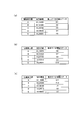
- FIGS. 24A to 24C are diagrams for explaining the tables T1, T2, and T3 created in the method 1.
- FIG. Specifically, the identification number (K1_10000) of the information display A is associated with the data D1 related to the first page.
- the identification number (K2 — 01000) of the information display B is associated with the data D2 related to the second page.
- the identification number (K3_00100) of the information display C is associated with the data D3 related to the third page.
- the identification number (K4_00010) of the information display D is associated with the data D4 related to the fourth page.
- the identification number (K5_00001) of the information display E is associated with the data D5 related to the fifth page.
- the control device 120 stores the association data regarding these groups G1 in the storage unit 220 as one table T1.
- the identification number (K1_10000) of the information display A is associated with the data D11 related to the 11th page.
- the identification number (K2 — 01000) of the information display B is associated with the data D12 related to the 12th page.
- the data of the first page to the third page may be assigned again to the information displays C, D, and E.
- control device 2120 waits for a predetermined operation in step S15. For example, when an operation related to page turning or an operation for specifying a page to be displayed is performed by the user, and the target page is a page not currently displayed on the information displays A to E, Select a table based on the operation.
- control device 2120 displays predetermined information (D1, D2, D3, D4, D5) on the predetermined information displays A, B, C, D, E in step S16. Control each information display.
- the table T2 is selected, and the information display is performed based on the table T2.
- Information (D6, D7, D8, D9, D10) is sequentially displayed on the devices A, B, C, D, E.
- the information (D6) on the sixth page is displayed on the information display A.
- the user can browse the information (D6) on the sixth page by returning to the information display A in the manner of turning the page of the book.
- the information display E displaying the information (D5) on the fifth page that is still being browsed is also subject to rewriting, but the timing for transmitting the drawing data signal for rewriting is set later.
- the display of the information display E is rewritten while browsing the information (D6) on the sixth page or after returning to the information display A in the manner of turning the page of the book, It is possible to avoid rewriting the display on the information display E during browsing the information (D5) on the fifth page.
- step S14 is executed without passing through step S13.
- the control device 2120 divides the acquired information into information groups having an information amount that does not exceed the information amount that can be displayed on the information display.
- the first to fifth pages are set in the group G1
- the second to sixth pages are set in the group G2
- the third to seventh pages are set in the group G3.
- 5 consecutive pages of the data to be displayed for 12 pages are set as a group.
- a plurality of groups are created so that the configuration of five pages is shifted by one page.
- the identification number (K1_10000) of the information display A is associated with the data D2 related to the second page.
- the identification number (K2 — 01000) of the information display B is associated with the data D3 related to the third page.
- the identification number (K3 — 00100) of the information display C is associated with the data D4 related to the fourth page.
- the identification number (K4_00010) of the information display D is associated with the data D5 related to the fifth page.
- the identification number (K5_00001) of the information display E is associated with the data D6 related to the sixth page.
- the control device 2120 stores the association data regarding these groups G2 as a table T2 in the storage unit.
- the identification number (K1_10000) of the information display A is associated with the data D3 related to the third page.
- the identification number (K2 — 01000) of the information display B is associated with the data D4 related to the fourth page.
- the identification number (K3 — 00100) of the information display C is associated with the data D5 related to the fifth page.
- the identification number (K4_00010) of the information display D is associated with the data D6 related to the sixth page.
- the identification number (K5_00001) of the information display E is associated with the data D7 related to the seventh page.
- the control device 2120 stores the association data regarding these groups G3 as a table T3 in the storage unit.
- the following display method is possible. For example, when the user browses the information (D5) on the fifth page displayed on the information display E, when the page turning operation is performed, the table T2 is selected, and the information display A based on the table T2 is selected. , B, C, D, and E display information (D2, D3, D4, D5, and D6), respectively. As a result, the information (D6) on the sixth page is displayed on the information display E being browsed. When the user returns to the information display D from the information display E in the manner of turning the page of the book, the user can browse the information (D5) on the fifth page.
- the page designated on the information display A can be displayed while the information display A is viewing the information (D1) on the first page.
- the information (D3) on the third page is displayed on the information display A
- the information (D4) on the fourth page is displayed on the information display B.
- the device C displays the fifth page information (D5)
- the information display D displays the sixth page information (D6)
- the information display E displays the seventh page information (D7).
- a control signal (drawing data signal for rewriting display information) transmitted from the control device to the information display is sequentially transmitted to each information display A, B, C, D, E.
- the display information is rewritten for each information display.
- a control signal including an identification signal for identifying the information display A in a drawing data signal for displaying the information D1 is displayed on each information display A, B, C, Transmitted to D and E.
- the transmitted identification signal in the determination circuit included in the information display A is the identification information of the information display A (in the embodiment, information determined by the arrangement pattern of the insulating portion and the conductive portion included in the determination circuit.
- Information D1 is displayed in the information display area 110a of the information display A itself.
- the transmitted identification signal is transmitted to the identification information of the information displays B to E (in the embodiment, the insulation included in the determination circuit).
- the information D1 is not displayed in the information display areas 110a of the information displays B to E. Display rewriting based on such determination is sequentially performed in the information displays B to E, and information (D1, D2, D3, D4, D5) for five pages is displayed on all the information displays A to E, respectively.
- the information display system 2100 according to the second embodiment has the following action / effect in addition to the action / effect of the information display system according to the first embodiment.
- the information display system 2100 divides the acquired information into groups of information having an amount of information that does not exceed the amount of information that can be displayed on the plurality of information displays A to E, and the information included in the plurality of groups is divided.
- a table assigned to each of the information indicators A to E is created for each group, and when a signal for selecting a group is input, information is sent to each of the information indicators A to E based on the table of the selected group.
- the control device includes a device-side connection mechanism that stacks a plurality of information displays and binds them to a plurality of information displays.
- the device-side coupling mechanism includes a device-side conducting portion and a device-side insulating portion.
- the control device includes an image signal transmission unit that transmits an image signal to a plurality of information displays, and an identification signal transmission unit that transmits an identification signal for identifying an information display to be rewritten to a predetermined image to the plurality of information displays. And have.
- the arrangement pattern of the device-side conductive portion and the device-side insulating portion is made different for each of the plurality of information indicators to be connected.
- the control device can designate an information display device whose display should be rewritten to a predetermined image based on the image signal, using the identification signal of the control signal transmitted as the control signal including the image signal and the identification signal or the identification signal transmitted together with the image signal.
- the identification signal corresponds to the arrangement pattern of the device-side conductive portion and the device-side insulating portion.
- the control device From the control signal identification signal transmitted as a control signal including the image signal and the identification signal, or the identification signal transmitted together with the image signal, and this identification information given to itself by connection with the control device, the control device It is determined whether or not the image signal transmitted from the device rewrites its own display. This determination is performed by an electronic circuit that performs a logical operation, provided on the information display side, and an identification signal of a control signal transmitted as a control signal including an image signal and an identification signal, or an identification signal transmitted together with the image signal By comparing the given identification information, the display is rewritten only in the information display that is determined to be the information display whose display should be rewritten to the predetermined image corresponding to the image signal.
- FIG. 26 is a perspective view showing a schematic configuration of the information display system 3100.
- FIG. 27 is an exploded perspective view of the information display system 3100.
- FIG. 28 is a cross-sectional view of the information display system 3100 taken along the line XX.
- the information display system 3100 includes a plurality of information displays 3110 and a control device 3120 that controls display of information on the plurality of information displays 3110.
- the control device 3120 is configured as an exterior body C.
- the control device 3120 includes a CPU 20, a graphic controller 30 (see FIG. 18), a memory, and the like.
- the control device 3120 transmits an image signal to the information display 3110 and controls the information display 3110 to display a predetermined image corresponding to the image signal.
- the power supply necessary for executing information display is connected to the control device 3120 by mounting a power source such as a sheet battery or a coin-type battery on the exterior body C, or connected to the control device 3120 provided on the exterior body C. This can be done by connecting an external power supply to the connected terminal.
- a power source such as a sheet battery or a coin-type battery
- the information display system 3100 has a configuration in which the control device 3120 is provided in the outer package C of the information display device bound in a booklet shape. However, the information display system 3100 is bound in a booklet shape. By providing the control device 3120 arranged separately from the exterior body C, the control device 3120 may be connected to a connection terminal provided in the exterior body C to control the information display.
- the protruding portion 3121 provided in the control device 3120 protrudes from the mounting portion Ca of the exterior body C on which the information display 3110 is stacked and is formed in parallel in one direction.
- Some of the protrusions 3121 are formed with a conductive member, and are electrically connected to an electronic device such as the CPU 20.
- a predetermined number of holes 3110h provided in the information display 3110 are formed in parallel with one side of the information display 3110. Some of the holes 3110h are formed with a conductive member, and are configured to be electrically connectable to the protruding portion 3121 having conductivity. The protrusion 3121 and the hole 3110h are configured to be engageable with each other.
- the protruding portion 3121 that does not include a conductive member and the hole (through hole) 3110h that includes a conductive member are portions that connect the information display 3110 and the control device 3120 exclusively physically and mechanically.
- the protrusion 3121 constitutes a device-side coupling mechanism that overlaps the information display 3110 and binds in a booklet shape
- the hole 3110h constitutes a display-side coupling mechanism that is coupled to the device-side coupling mechanism.
- Some of the protrusions 3121 and the holes 3110h can be formed independently of the electrical connection as structural members that exclusively form a physical and mechanical engagement structure.
- the protrusion 3121 provided with the conductive member constitutes a conductive connection part 3121E on the control device side, and the hole 3110h provided with the conductive member constitutes a conductive connection part on the information display side. Details of the conductive connection portion 3121E will be described later (see FIG. 29).
- the information display system 3100 shown in FIG. 26 includes a fastener 3130 having at least a surface formed of an insulating material.
- the information display 3110 stacked by inserting the hole 3110h into the protrusion 3121 is fixed by the insulating fastener 3130 in a state where the protrusions 3121 formed with the conductive portions do not leak.
- FIG. 29 is a sectional view taken along line YY of FIG.
- the conductive member sometimes referred to as an electrode
- each conductive connection portion hole portion 3110h provided with a conductive member
- the control device 3120 includes a plurality of protrusions 3121.
- a plurality of protrusions 312 also referred to as conductive connection portions 3121E
- a conductive member are used to control signals (image signals) to a plurality of information indicators 3110. And an identification signal).
- the plurality of protrusions 3121 of the control device 3120 include identification signal transmission units 3123b, 3123d, 3123f, and 3123h (hereinafter, appropriately referred to as identification signal transmission unit 3123) and conduction connection units 3124a, 3124c, 3124e, and 3124g. (Hereinafter, referred to as the conductive connection portion 3124 as appropriate) and the engagement portion 3121X that does not require the provision of a conductive member.
- the conductive connection portions 3121E of the plurality of protrusions 3121 of the control device 3120 also include an image signal transmission unit 3122 (see FIG. 34) that transmits image signals to the plurality of information indicators 3110.
- the identification signal transmission unit 3123 (in the example shown in FIG. 29, four projections 3123b, 3123d, 3123f, and 3123h) transmit identification signals output from the CPU to all the information indicators 3110. Specifically, the identification signal transmission unit 3123 transmits an identification signal for identifying the information display 3110 to be rewritten to a predetermined image corresponding to the image signal to all of the plurality of information displays 3110. The identification signal is transmitted corresponding to the image signal, for example, included in the image signal or transmitted together with the image signal.
- the arrangement pattern of the device-side conductive portion and the device-side insulating portion which will be described later, is formed in the horizontal direction of a plurality of conductive connection portions 3124 (four protrusions 3124a, 3124c, 3124e, and 3124g in the example shown in FIG. 29). Is done.
- FIG. 30A shows a horizontal sectional view (DX-DY plane) of the conductive connection portion 3124a
- FIG. 30B shows three information indicators on the conductive connection portion 3124a.
- An enlarged vertical sectional view (DY-DZ plane) of a portion where 3110 (# 1, # 2, # 3) are overlapped and connected is shown.
- the conductive connection portion 3124a is formed with an insulating portion at a position in the height direction connected to the information indicator # 1, and the information indicator # 2 and A conducting portion is formed at a position in the height direction connected to # 3.
- FIG. 30A shows a horizontal sectional view (DX-DY plane) of the conductive connection portion 3124a
- FIG. 30B shows three information indicators on the conductive connection portion 3124a.
- An enlarged vertical sectional view (DY-DZ plane) of a portion where 3110 (# 1, # 2, # 3) are overlapped and connected is shown.
- the conductive connection portion 3124a is formed with an insulating portion at a position in
- each of the plurality of conductive connection portions 3124 (3124a, 3124c, 3124e, 3124g) has a placement position (height direction) of each of the plurality of information indicators 3110 (# 1 to # 16). Insulating part 3125 is formed in correspondence with (the position).
- the arrangement pattern of the device-side conductive portion and the device-side insulating portion corresponding to each of the plurality of information indicators 3110 is the number of conductive connection portions 3124 (3124a, 3124c, 3124e, 3124g) arranged in a row. Each is formed in the horizontal direction at the same height position.
- the insulating portion 3125 is formed at a predetermined height position of each of the plurality of conductive connecting portions 3124, thereby arranging the device-side conductive portion and the device-side insulating portion corresponding to each information display 3110.
- the pattern is formed in the horizontal direction at the same position in the height direction.
- the arrangement pattern of the device-side conductive portion and the device-side insulating portion is formed to be different for each of the plurality of information indicators 3110. Specifically, the arrangement patterns are formed differently depending on the placement positions of the plurality of stacked information indicators 3110. Note that the placement position of the information display 3110 indicates the position of each of the plurality of stacked information displays 3110 in the direction in which the conductive connection portion 3124 extends (DZ direction), and can also be referred to as a page position.
- the arrangement pattern of the device-side conductive portion and the device-side insulating portion formed in the direction (DY direction) formed in parallel with the conductive connection portion 3124 is the direction in which the conductive connection portion 3124 extends ( In the DZ direction), a plurality (16 in the example shown in FIG. 29) are formed.
- the connection portion 3124a serves as a device-side conduction portion for the # 2 information display 3110 and the # 3 information display 3110.
- the arrangement patterns of the device-side conductive portion and the device insulating portion formed at the same horizontal position in the height direction when the respective conductive connection portions 3124 (3124a, 3124c, 3124e, 3124g) are arranged are all different. Composed. Therefore, the arrangement pattern of the device-side conductive portion and the device insulating portion is configured to be different depending on the placement position of each of the plurality of information indicators 3110, that is, the page position.
- the image signal transmission unit 3122 and the identification signal transmission unit 3123 are protrusions made of a conductive material.
- Each protrusion in the example of the identification signal transmitter shown in FIG. 29, the four protrusions 3123b, 3123d, 3123f, and 3123h, and the image signal transmitter 3122 (not shown)) are a plurality of superimposed information. It becomes a connection part which conduct
- the image signal transmission unit 3122 which is the conductive connection unit 3121E on the control device side is a projecting portion made of a conductive material, and is made of the same conductive material as the identification signal transmission unit 3123.
- the image signal transmission unit 3122 is a connection unit that conducts at all positions in the height direction corresponding to each of the plurality of information indicators 3110 that are overlaid.
- FIG. 31 is a plan view illustrating the information display 3110.
- the information display 3110 is a rectangular thin panel type, and can be used as electronic paper or the like.
- the rectangular shape referred to here is a shape generally known for notebook paper or the like, and includes a case where corners are cut round or a corner is cut slightly linearly.
- an information display area 3110a for displaying information is formed.
- the information display 3110 includes a pair of substrates (observation side substrate 3181, back side substrate 3182).
- the observation side substrate 3181 is transparent.
- the information display area 3110a is formed on the observation side substrate 3181.
- the observation side substrate 3181 is formed with observation side electrodes (not shown in FIGS. 31 and 32).
- a back side electrode 3192 is formed on the back side substrate 3182.
- a predetermined gap (gap) is formed between a pair of substrates on which a pair of display electrodes (observation side electrode, back side electrode) is formed, and between the observation side electrode and the back side electrode,
- a display medium layer 3115 is disposed.
- each information display device is aligned, that is, the display screen of each information display device is overlaid, but the back side of the two information display devices is pasted.
- an information display device having display screens on both the front and back sides may be used.
- the display medium layer 3115 may be a gas layer (including a vacuum layer) or a liquid layer in which particles containing charged particles are arranged as a display medium, or a cholesteric liquid crystal layer. Each has a display memory property and can hold a predetermined image displayed even in a non-powered state.
- the display medium is at least two kinds of particle groups having chargeability and optical reflectance, for example, negatively charged white particles or positively charged black particles. These chargeable particles move in gas (including vacuum) or liquid toward the observation side electrode (or back side electrode) by an electric field formed by a voltage applied between the substrates.
- the back side substrate 3182 is formed wider than the information display area 3110a and forms the skeleton of the information display 110.
- a drive circuit 3200 is disposed on the back side substrate 3182 with an electrode 3117 interposed therebetween. The electrode 3117 and the drive circuit 3200 are covered with an insulating film 3118.
- the information display 3110 includes a plurality of drive circuits 3200a to 3200e on the outside of the information display area 3110a on a plane.
- the drive circuits 3200a to 3200e are also called driver ICs, and this driver IC has a function of invalidating OUTPUT (signal output to the information display area 3110a) and is applied to the observation side electrode and the back side electrode.
- this driver IC has a function of invalidating OUTPUT (signal output to the information display area 3110a) and is applied to the observation side electrode and the back side electrode.
- the information display 3110 side is electrically connected to conductive connection portions 3124a, 3124c, 3124e, 3124g, 3124i, and 3124k (white circles in the drawing) which are conductive connection portions 3121E of the protruding portion 3121 on the control device 3120 side.
- Conductive connection portions 3131a, 3131c, 3131e, 3131g, 3131i, and 3131k (white circles in the figure) to be connected are formed.
- the plurality of holes 3110h constituting the conductive connection part on the information display 3110 side also includes an image signal receiving unit 1120A that receives an image signal transmitted from the image signal transmitting unit 3122 of the control device 3120 (See FIG. 34). Further, the plurality of holes 3110h of the information display 3110 have an engagement hole (through hole) 3131X that does not have a conductive portion. (See Figure 31)
- the identification signal receivers 3131b, 3131d, 3131f, 3131h, 3131j, 3131l can be electrically connected to the identification signal transmitters 3123b, 3123d, 3123f, 3123h, 3123j, 3123l of the control device 3120 that transmits the identification signal. .
- the conductive connection portions 3131a, 3131b, 3131c, 3131d, 3131e, 3131f, 3131g, 3131h, 3131i, 3131j, 3131k, and 3131l on the information display 110 side are connected to the conductive connection portion 3121E on the control device 3120 side. It is necessary to make it a connection part.
- the conductive connection portions 3131a to 3131l on the information display 3110 side may be conductive connection portions having the same structure, or may be conductive connection portions having different structures.
- FIG. 33 is an enlarged view of a hole 3110h (a hole in which a conductive connection portion 3131a is formed) provided with a conductive member in a plan view of the information display 3110.
- the hole 3110h formed on the back side of the information display 3110 (here, the back side substrate 182) is penetrated.
- the electrode 3117 has an exposed portion 3117a.
- the exposed portion 3117a protrudes toward the center of the hole 3110h and is exposed.
- the exposed portion 3117a comes into contact with the protruding portion 3121 (conductive connection portion 3121E) on the control device 3120 side provided with a conductive member, so that the information display 3110 and the control device 3120 can be electrically connected to each other.
- FIG. 34 is a circuit diagram for explaining a connection circuit configuration and determination circuit configuration between the information display 3110 and the control device 3120 according to this embodiment. is there.
- FIG. 34 shows a part of a circuit configuration of a connection portion between the control device 3120 and one information display 3110.
- FIG. 35 is a diagram for explaining drive circuits 3200a to 3200e arranged in the information display 3110 according to this embodiment and connection lines connected to the drive circuits 3200a to 3200e.
- the identification signal transmitting units 3123b, 3123d, 3123f, 3123h, 3123j, 3123l (black circles in the drawing) of the protrusions (conductive connection units 3121E) provided with the conductive members of the control device 3120 are the identification signal receiving unit 3131b.
- 3131d, 3131f, 3131h, 3131j, and 3131l (black circles in the drawing) are physically connected and electrically connected.
- the conductive connection portions 3124a, 3124c, 3124e, 3124g, 3124i, 3124k are the conductive connection portions 3131a, 3131c. 3131e, 3131g, 3131i, and 3131k (white circles in the drawing) are physically connected and electrically connected.
- the control device 3120 includes a conduction connection portion 3124 (a conduction connection portion 3124c in FIG. 34) in which the insulating portion 3125 is formed in the plurality of conduction connection portions 3124, so that one device side An arrangement pattern of the insulating portion and the five device-side conductive portions is configured.
- a conduction connection portion 3124 a conduction connection portion 3124c in FIG. 34
- the control device 3120 has six conductive connection portions 3124, one to six device-side insulating portions can be provided, and 26 arrangement patterns can be obtained. That is, the control device 3120 can provide 2N (2 to the Nth power) arrangement patterns when N conductive connection portions 3124 are provided.
- a determination circuit is formed between 3131k and the drive circuits 3200a to 3200e.
- an arrangement pattern of one device-side insulating portion (3124c) and five device-side conductive portions (3124a, 3124e, 3124g, 3124i, 3124k) is formed as identification information, and information display It becomes the identification information for identifying the information display 3110 in the judgment circuit 3310 of the device 3110.
- one device-side insulating portion formed in the horizontal direction at the same height position of the plurality of conductive connection portions 3124 on the control device 3120 side corresponding to each information display 3110 is one per information display 3110. You may provide, and you may provide two or more. Moreover, the insulating part does not need to be provided in the said horizontal direction corresponding to one information display among the some information displays with which an information display system is provided. That is, there are a plurality of arrangement patterns of the device-side insulating portion and the device-side conductive portion formed in the horizontal direction at the same height position of the plurality of conductive connection portions 3124 on the control device 3120 side corresponding to each information display 3110. It suffices if they are configured to be different from each other in the horizontal direction at the height position corresponding to each of the information displays.
- the identification information that can identify 26 (64) information displays 3110 is arranged in 26 (64) arrangements. Can be obtained in a pattern.
- the output line of the determination circuit 3310 is branched and connected to each of the drive circuits 3200a to 3200e.
- the determination circuit 3310 is connected to the drive circuits 3200a to 3200e via the output enable lines 3320a to 3320e of the drive circuits 3200a to 3200e.
- the determination circuit 3310 is electrically connected to the drive circuits 3200a to 3200e by enabling or disabling the output enable (OUTPUT-ENABLE) of the drive circuits 3200a to 3200e included in the information display according to the determination result described above. Configured to be connected.
- circuit wiring different from the example shown in FIG. 34 may be connected to the chip select lines 3320a to 3320e of the drive circuits 3200a to 3200e. It is not limited to.
- the determination circuit 3310 has a configuration including the XNOR circuit 3311 and the NAND circuit 3312. However, the determination circuit 3310 may be configured to include another logic circuit.
- the determination circuit 3310 provided in the information display 3110 includes an IC chip (memory) storing information for specifying the information display, for example, a page number, and an identification signal transmitted from the control device 3120 together with the image signal. And page number information stored in the IC chip can be compared to determine whether they match or not.
- IC chip memory
- the arrangement pattern of the device-side insulating portion and the device-side conductive portion included in the control device 3120 is not used as identification information for each information display 3110.
- An information display provided with an IC chip (memory) storing the page numbers as described above is complicated in configuration and requires an extra IC chip, resulting in high cost.
- the circuit configuration is simpler than that provided with a storage unit, and that an expensive IC chip is not required, so that the cost can be reduced.
- FIG. 36 is a flowchart illustrating processing in the information display system 3100.
- the processing operation of the information display system 3100 will be described with reference to FIG. Specifically, a process in which the control device 3120 displays an image on one information display 3110 of the plurality of information displays 3110 will be described.
- 64 information displays 3110 having the configuration shown in FIG. 34 are bound to one control device 3120, and the # 2 information display corresponding to the second page corresponds to the image signal.
- a case where a predetermined image is displayed will be described as an example. Therefore, a control signal including an identification signal for indicating that it is an image signal of image data to be displayed on the # 2 information display on the second page is transmitted from the CPU of the control device to the information display on the second page.
- the predetermined image corresponding to the image signal is displayed.
- the identification signal can also be transmitted together with the image signal.
- the control device 3120 transmits a control signal including an identification signal for indicating that the display of the # 2 information display is rewritten to all the information displays 3110 bound. Therefore, the control signal includes an identification signal and an image signal of image data to be displayed on the # 2 information display. An identification signal for identifying the # 2 information display may be transmitted together with the image signal of the image data to be displayed on the # 2 information display. Specifically, the control signal is transmitted from the conductive connection part 3121E on the control device side and received by the conductive connection part on the information display side. The image signal of the image data is transmitted from the image signal transmission unit 3122 to the information display 3110, and the identification signal is transmitted from the identification signal transmission unit 3123 to the information display 3110.
- the conductive connection portions 3124a, 3124e, 3124g, 3124i, and 3124k connected to the # 2 information display are conductive portions and are connected to the information display 3110.
- the conductive connection portion 3124c connected to the display device is an insulating portion by forming the insulating portion 3125, and is insulated from the information display device 3110.
- a control signal including an identification signal for indicating rewriting the display of # 2 information display is transmitted to all information displays 3110. That is, the identification signal for rewriting the display on the # 2 information display is transmitted to the other information displays other than the # 2 information display (3123b, 3123d, 3123f, 3123h, 3123j, 3123l).
- To the identification signal receiving unit (3131b, 3131d, 3131f, 3131h, 3131j, 3131l) and enters the determination circuit 310 included in each information display.
- the arrangement pattern of the insulating portion and the conductive portion in the conductive connection portions 3124a, 3124c, 3124e, 3124g, 3124i, and 3124k to which the information display other than the # 2 information display is connected is shown in # 2 in FIG.
- the arrangement pattern of the insulating portion and the conductive portion is different, and the identification corresponding to each information display Forming information. Therefore, the determination circuit 310 of each information display device connected to the control device has different identification information.
- each information display unit compares the identification signals received by the identification signal receiving units 3131b, 3131d, 3131f, 3131h, 3131j, and 3131l with the identification information given to each information display unit, so that they match. It is determined whether or not they match.
- the information display device 3110 of the second page whose display is to be rewritten is identified from the identification signal transmission units 3123b, 3123d, 3123f, 3123h, 3123j, 3123l of the control device 3120 to the determination circuit 3310 on the information display device 3110 side.
- the identification signal (for example, “010000”) is transmitted to all 64 information displays 3110.
- the outputs of the identification signal receivers 3131b, 3131f, 3131h, 3131j, 3131l are “0”.
- the output of the identification signal receiving unit 3131d is “1”.
- the outputs of the conductive connection portions 3131a, 3131e, 3131g, 3131i, and 3131k are grounded via the conductive portions 3124a, 3124e, 3124g, 3124i, and 3124k of the conductive connection portion, and become “0”.
- the conductive connection part 3131c connected to the conductive connection part 124c which is an insulating part is not grounded, “1” is output.
- the truth value on the output side of the XNOR circuit 3311 of the determination circuit 3310 is “111111”.
- the outputs of all the XNOR circuits 3311 are “1”, and the outputs of the NAND circuits 3312 are “0”. That is, in the # 2 information display, the identification information of the # 2 information display matches the received identification signal (step 321: YES).
- the switch 3350 is turned off (step 331), the output enable (OUTPUT-ENABLE) of the drive circuits 3200a to 3200e is enabled (step 341), and the # 2 information display from the drive circuits 3200a to 3200e is activated.
- the image data is output to the information display area 110a (step 351). In this way, the # 2 information display is rewritten (step 361).
- an insulating portion 3125 is formed in the conductive connection portion 3124a corresponding to the conductive connection portion 3131a.
- the control device 3120 displays the image signal of the image data to be displayed on the second page and the image data on the information display on the second page for the # 1 information display.
- the identification signal “010000” is also transmitted to the identification signal receivers 3131b, 3131d, 3131f, 3131h, 3131j, and 3131l of the # 1 information display.
- the # 1 information display compares this identification signal with the identification information given to the # 1 information display through the conductive connection parts 3131a, 3131c, 3131e, 3131g, 3131i, 3131k, and is it consistent? Determine whether or not.
- the image signal of the image data to be displayed on the second page from the identification signal transmitters 3123b, 3123d, 3123f, 3123h, 3123j, 3123j, 3123l of the control device 3120 to the determination circuit 3310 on the # 1 information display 3110 side.
- An identification signal (“010000”) indicating that is transmitted.
- the outputs of the identification signal receiving units 3131b, 3131f, 3131h, 3131j, and 3131l are “0”.
- the output of the identification signal receiving unit 3131d is “1”.
- the outputs of the conductive connection portions 3131c, 3131e, 3131g, 3131i, and 3131k are grounded via the conductive portions 3124c, 3124e, 3124g, 3124i, and 3124k of the conductive connection portion, and become “0”.
- the conductive connection part 3131a connected to the insulating part 3124a of the conductive connection part in which the insulating part 125 is formed is not grounded, “1” is output. Therefore, in the # 1 information display 3110, the truth value on the output side of the XNOR circuit 3311 of the determination circuit 3310 is “001111”. Since the outputs of all the XNOR circuits 3311 are not “1”, the output of the NAND circuit 3312 is “1”. That is, in the # 1 information display, the identification information of the # 1 information display and the identification signal do not match (step 321: NO).
- the switch 3350 is turned on (step 332), the output enable (OUTPUT-ENABLE) of the drive circuits 3200a to 3200e is disabled (step 342), and the information from the drive circuits 3200a to 3200e is displayed on the information display.
- Image data is not output to the display area 110a (step 352). That is, the rewriting of the # 1 information display is not executed (step 362).
- # 1 information display corresponding to the first page is described as an example, but other information displays other than the # 2 information display are similarly not rewritten.
- 3131k and the connection pattern 3124a, 3124c, 3124e, 3124g, 3124h, and 3124k on the control device 120 side are formed by the arrangement pattern of the device-side conductive portion and the device-side insulating portion.
- the control device 3120 has been described as an example in which a predetermined image displayed on one information display 3110 (# 2 information display) is rewritten.
- the system 3100 can also sequentially rewrite and display a predetermined image to be displayed on each of the plurality of information display devices 3110 by repeating the processes of steps S31 to S361 described above.
- an image signal corresponding to a predetermined image to be displayed on each information display 3110 is identified with respect to a plurality of information displays 3110, and an identification signal for identifying each information display And send sequentially.
- the control signal transmitted from the control device 3120 to the information display 3110 may be configured by an image signal and an identification signal, or may be configured as an image signal including the identification signal.
- each of the plurality of information indicators 3110 receives the image signal and the identification signal transmitted from the control device 3120, and identifies based on the arrangement pattern of the conductive portion and the insulating portion formed on the control device 3120 side. Information is given to a determination circuit included in each information display, and based on the identification information and the identification signal, it is determined whether or not to display an image corresponding to the image signal, and then determined to be displayed. In this case, image data corresponding to the image signal is output from the drive circuit 3200, and a predetermined image based on the image data is displayed. This operation is sequentially executed in each of the plurality of information displays 3110.
- the information display system 3100 can rewrite each of the plurality of information displays 3110 in order of page numbers (order of placement positions), or can rewrite at random.
- the configuration of the determination circuit shown in the above embodiment is an example.
- the XNOR and NAND logic circuits are used for comparison, but for example, a method of receiving an input from the CPU terminal once by a shift register is also conceivable.
- the identification signal received from the control device 3120 is compared with the identification information given to each information indicator 3110 by connection with the control device 3120, and it is detected whether they match or not.
- the circuit to be determined is not limited to the logic circuit (XNOR, NAND) described in the embodiment of the present invention, and may be a commonly used electronic circuit such as another logic circuit or a memory circuit.
- the plurality of protruding portions 3121 formed in the control device 3120 are stacked in a booklet shape by overlapping the plurality of information displays 3110 and the plurality of information displays.
- a device-side coupling mechanism coupled to each of 3110 is configured.
- some of the protrusions 3121 (conductive connection part 3121E) provided with a conductive member among the protrusions 3121 constitute a transmission part that transmits a control signal for controlling the information display 3110.
- some of the conductive connection units 3121E transmit an identification signal for identifying an image signal transmission unit 3122 for transmitting an image signal and an information display 3110 to be rewritten to a predetermined image corresponding to the image signal.
- a signal transmission unit 3123 and a conductive connection unit 3124 that forms an arrangement pattern of the device-side conductive portion and the device-side insulating portion, which is identification information for identifying the information display in the connected information display 3110 Constitute.
- the conduction connection portion 3124 includes a conduction connection portion 3124 in which an insulating portion 3125 is formed, and the conduction connection portion 3124 has a device-side conduction portion and a device-side insulation portion.
- Identification information is formed by the arrangement pattern of the device-side conductive portion and the device-side insulating portion formed when a plurality of the conductive connection portions 3124 are arranged, and this identification information is given to the information display 3110. Specifically, the identification information formed at the position when the plurality of information displays 3110 are overlapped is given to each of the information displays 3110 connected to the corresponding position.
- This arrangement pattern is formed so as to be different corresponding to the position where each of the plurality of information displays 3110 is connected, and is given to each of the plurality of information displays 3110 as different identification information. Therefore, the control device 3120 can specify the information display 3110 located at the position corresponding to the arrangement pattern using the identification signal.
- the determination circuit 3310 includes the identification signal received by the identification signal receiving units 3131b, 3131d, 3131f, 3131h, 3131j, and 3131l, and the conductive connection units 3131a, 3131c, 3131e, 3131g, 3131h, and 3131k. Is compared with the identification information provided through the control unit 3 to determine whether or not they match, and the output enable of the drive circuits 3200a to 3200e is valid only for the information display 3110 that matches the identification information. Image data corresponding to the signal is output to display a predetermined image.
- the control device 3120 transmits the identification signal to each of the plurality of information displays 3110, so that only the information display 3110 identified by the identification signal and the identification information has a predetermined image. Can be displayed.
- the control device 3120 has a plurality of information displays 3110 overlapped in a booklet shape regardless of whether or not the plurality of information displays 3110 constituting the “page” are in a spread state.
- Each information display device 3110 can be individually identified, and a predetermined image can be displayed on the information display device 3110 whose display should be rewritten to a predetermined image corresponding to the image signal.
- the control device 3120 since the device-side conductive portion and the device-side insulating portion are formed in the conductive connection portion 3124, in the information display 3110, all the conductive connection portions are formed as conductive portions. Identification information for identifying each of the plurality of information indicators 3110 connected to the control device 3120 can be given. Therefore, even if the configuration of the conductive connection portion 3121E of each information display device 3110 is the same, identification information for identifying each information display device 3110 can be taken into the determination circuit 3310 of each information display device 3110. The information display device 3110 can be shared.
- control device side connection mechanism (also referred to as device side connection mechanism) is the protrusion 3121
- information display side connection mechanism (also referred to as display side connection mechanism) is the hole 3110h.
- the configuration of the device-side coupling mechanism and the display-side coupling mechanism can be changed.
- FIGS. 37A and 37B are diagrams illustrating a modification of the device-side coupling mechanism.
- a bending member 3140 is attached to the exterior body C instead of providing the fastener 130.
- One end 3140 a of the bending member 3140 is attached to the exterior body C.
- the other end 3140 b of the bending member 3140 is in contact with the end 3121 f of the protruding portion 3121 that is not fixed. That is, a closed annular structure is formed by the bending member 3140 and the protruding portion 3121.
- An insulating portion 3135 is provided at a predetermined position of the protruding portion 3121 serving as the conductive connection portion 3124, and an arrangement pattern of the device-side conductive portion and the device-side insulating portion is formed.
- the bending member 3140 is configured to be movable in a direction in which the end 3140b and the end 3121f of the protrusion 3121 are separated from each other.
- the ring structure closed by the part 3121).
- the curved member 3140 can be formed of a conductive material.
- an insulating portion 3135 is provided only at a predetermined position of the protruding portion 3121 so as to form an arrangement pattern of the device-side conductive portion and the device-side insulating portion.
- the portion (3121_2) other than the curved portion of the bending member 3140 may be configured as a conductive connection portion 3124 having the same structure as the protruding portion 3121 (3121_1).
- the information display 3110 is moved from the right side to the left side in FIG. 37B, and information is displayed on the information display 3110 located on the left side.
- the formation position of the insulating portion 3135 can correspond to the protruding portions 3121_1 and 3121_2, or can be completely irrelevant, but is provided to a plurality of connected information indicators 3110.
- the arrangement pattern of the conductive portion and the insulating portion is made different.
- FIG. 38 is a diagram for explaining another modification of the device-side coupling mechanism.
- one end 3140a of the bending member 3140 is attached to the exterior body C via a rotation mechanism 3150.
- the bending member 3140 is rotated in the direction of the arrow in FIG. 38 by the rotation mechanism 3150, so that the end 3140b and the end 3121f are separated from each other.
- the portion (3121_2) other than the curved portion of the bending member 3140 is configured as a conductive connection portion 3124 having the same structure as the protruding portion 3121 (3121_1).
- FIG. 38 is a diagram for explaining another modification of the device-side coupling mechanism.
- one end 3140a of the bending member 3140 is attached to the exterior body C via a rotation mechanism 3150.
- the bending member 3140 is rotated in the direction of the arrow in FIG. 38 by the rotation mechanism 3150, so that the end 3140b and the end 3121f are separated from each other.
- only the protruding portion 3121 (3121_1) may be used as the conductive connection portion 3124.
- An insulating portion 3135 may be provided on all the surfaces of all the protruding portions 3121_2 so that no conductive connection is formed in the information display 3110 moved to the left side in FIG. In this case, the display can be rewritten by identifying the information display only from the information display on the right side, so the spare information display is held on the left side and is used for replacing the failed information display. It can be bound to an information display system.
- the information display 3110 is configured to provide the hole 3110h on the back side substrate of the information display, but is not limited thereto.
- the information display 3110 may be configured to provide a hole 3110h in a flexible circuit board (FPC) 3400 mounted on one side of the information display.
- the information display 3110 may be configured to include a hole 3110 h and a drive circuit 3200 in a flexible circuit board (FPC) 3400.
- FPC flexible circuit board
- the information display 3110 includes a tape carrier package (TCP) 3410 provided with a drive circuit 3200 on the substrate (observation side substrate 3181 or back side substrate 3182) of the information display 3110. And a flexible circuit board (FPC) 3400 provided with a hole 3110h may be connected to be mounted.
- TCP tape carrier package
- FPC flexible circuit board
- the protruding portion 3121 has a substantially cylindrical shape and the horizontal cross-sectional shape is circular.
- the horizontal portion of the protruding portion 3121 may not be circular. Good. It may be oval or square.
- a circular shape is preferable.
- one surface of the information display 3110 is the observation side.
- an information display having an observation surface on both sides may be configured by bonding and integrating the back side substrates 3182 of the two information displays 110 together.
- the information display 3110 having such a configuration two pages are constituted by one page on the front side and one page on the back side.
- each of the two integrated information displays includes a conductive connection portion (hole 3110h), and the conductive connection portion 3121E on the control device side includes each of the two integrated information displays. It is formed so as to correspond to the conductive connection part (hole part 3110h).
- the display medium 3116 is not limited to a white display medium and a black display medium, and may be a display medium of another color.
- the display medium may be any display medium that is driven by a voltage applied to the opposite electrode and has display memory characteristics that can retain displayed information even when power supply from the power source is cut off.
- an electrophoretic information display device of a microcapsule type that drives a group of particles containing charged particles in a transparent insulating liquid may be used.
- it may be an electrophoretic information display device of a type in which particles containing charged particles are driven in a colored insulating liquid.
- a white display medium composed of negatively charged white particles is enclosed in a cell formed of partition walls together with a colored insulating liquid such as blue paraffin oil.
- an information display there are a type that uses spherical particles that are configured in two colors and differently charged polarities as a display medium (for example, a twisting ball system that rotates in a microcapsule) or a type that drives a cholesteric liquid crystal.
- a display medium for example, a twisting ball system that rotates in a microcapsule
- a type that drives a cholesteric liquid crystal can be used.
- the method of driving the particle group in a gas is preferable because the drive response speed is high and the display memory property is excellent.
- the drive circuit 3200 and the information display 3110 are integrated, but the drive circuit 3200 and the information display 3110 may be configured to be detachable. Note that in the case where the drive circuit 3200 and the information display 3110 are not integrated, it is necessary to provide connection means for electrically and physically detachably connecting the drive circuit 3200 and the information display 3110.
- this connection means for example, a concave connection terminal portion is provided in one of the information display and the drive circuit, a convex connection terminal portion meshing with the concave connection terminal portion is provided, and the concave connection terminal portion and the convex connection are provided.
- a configuration in which the drive circuit and the information display are detachably connected electrically and physically by fitting with the terminal portion can be exemplified.
- a convex terminal portion is provided on one of the information display and the drive circuit, a circular hole into which the convex terminal portion can be inserted, a slit hole having a cross shape, a circular hole,
- a hole having a combination of cross-shaped slit holes, a hole having a combination of a circular hole and a three-way slit hole, a hole in which a plurality of slit holes are gathered in a star shape, and a receiving portion having a star-shaped hole can be exemplified.
- the present invention includes various embodiments that are not described herein.
- each of the above-described embodiments can be combined, or the above-described embodiment and a modification can be combined. Therefore, the technical scope of the present invention is determined only by the invention specifying matters according to the scope of claims reasonable from the above description.
- Japanese Patent Application No. 2011-130593 (filed on June 10, 2011), Japanese Patent Application No. 2011-136540 (filed on June 20, 2011), and Japanese Patent Application No. 2011-225787. No. (filed Oct. 13, 2011) is hereby incorporated by reference in its entirety.
- the information display device, the control device, the information display system, and the information display method according to the present invention can individually identify a plurality of information display devices in a booklet-like state and are not opened ( Even when the bound booklet is closed), it is useful because predetermined information can be displayed on the corresponding information display.
- the display unit (display screen) for displaying information is composed of a plurality of information displays. Display rewriting of the display unit of each information display is performed individually. Since the display medium arranged in the display unit of each information display device has a display memory property, the display is maintained while the rewriting process is not performed. Therefore, for example, in the case of a configuration in which 32 information display units are bound, information for one page is displayed on each of the 32 display units, and the information display unit is turned up sequentially from the first page. You can read books (books) as if you were reading up to the 32nd page.
- the information display can be made thin with a total thickness of about 100 ⁇ m to 500 ⁇ m. In this case, even if 32 sheets are stacked and bound, it becomes a book-type information display system with a thickness of about 15 mm. It will not be inferior to a book. In the case of such an information display system for reading, the size of characters to be displayed is about 10 to 11 points, and the page size (display screen size) is about A5 to A4. If it is divided, it will be easier to read.
- the information display system displays the information read from the storage unit on each page one page at a time, and then can be made like a book that allows each page to be browsed.
- the textbook can be stored in the department and the necessary textbook information is displayed on all pages.
- the textbooks can be used for all textbooks, and the number of textbooks carried around for classes can be reduced.
- the system when browsing the range of textbooks from page 20 to page 30 in a Japanese language class, the system reads the textbook data in Japanese language and displays 11 pages from page 20 to page 30. It can be used to browse and browse the necessary pages in class.
- the information display device, the control device, the information display system, and the information display method according to the present invention can individually identify a plurality of information display devices in a booklet-like state, and the identified corresponding information display device. This is useful because predetermined information can be displayed.
Landscapes
- Engineering & Computer Science (AREA)
- Physics & Mathematics (AREA)
- Computer Hardware Design (AREA)
- General Physics & Mathematics (AREA)
- Theoretical Computer Science (AREA)
- Control Of Indicators Other Than Cathode Ray Tubes (AREA)
- Electrochromic Elements, Electrophoresis, Or Variable Reflection Or Absorption Elements (AREA)
Abstract
情報表示器(110)は、制御装置と連結される連結機構とを有する。連結機構は、制御装置と電気的に接続される導通部分と、制御装置と電気的に絶縁された絶縁部分と、を有する。導通部分には、制御信号を受信する制御信号受信部が形成されている。導通部分と絶縁部分との配置パターンと、制御信号受信部によって受信した制御信号とに基づいて、情報表示器自身の表示情報を書き換えるか書き換えないかを決定するように構成された判定回路を有する。
Description
本発明は、複数の表示用電極と、複数の表示用電極の間に配置され、且つ表示用電極間に印加された電圧によって駆動される表示媒体とを有する情報表示器、制御装置、複数の情報表示器が一纏めに綴られた冊子型の情報表示システム及び情報表示方法に関する。
従来、少なくとも観察側となる基板が透明な2枚の基板を対向させて形成した空間に、電気的に駆動できる表示媒体を配置した情報表示パネルが情報表示器として知られている。
更に、紙と同様に、複数の情報表示器を見開き可能に綴った情報表示装置が開示されている(例えば、特許文献1参照)。このような情報表示装置によれば、情報表示器を冊子のように利用することができる。
ところが、特許文献1に記載された情報表示装置では、次のような問題点があった。すなわち、情報表示装置の各情報表示器を一度見開きにしなければ、本体に認識されず、各情報表示器に表示させる情報の書き換えを行うことができなかった。
そこで、本発明は、このような状況に鑑みてなされたものであり、複数の情報表示器を冊子状に綴った状態で個別に識別可能で、且つ該当する情報表示器に所定の情報を表示させることができる情報表示器、制御装置、情報表示システム及び情報表示方法を提供することを目的とする。
上述した課題を解決するため、本発明の第1の特徴に係る情報表示器は、少なくとも一方の基板が透明な情報表示領域を備える2つの基板と、前記2つの基板の間に対向して配置された複数の表示用電極と、複数の前記表示用電極間に配置されており前記表示用電極間に印加した電圧によって駆動される表示媒体と、前記表示用電極と電気的に接続されており制御装置から送信される制御信号によって前記情報表示領域に情報を表示するように前記表示用電極間に電圧を印加する駆動回路と、前記制御装置と連結される連結機構とを有する情報表示器であって、前記連結機構は、前記制御装置と電気的に接続される導通部分と、前記制御装置と電気的に絶縁された絶縁部分と、を有し、前記導通部分には、前記制御信号を受信する制御信号受信部が形成されており、前記導通部分と前記絶縁部分との配置パターンと、前記制御信号受信部によって受信した制御信号とに基づいて、当該情報表示器自身の表示情報を書き換えるか書き換えないかを決定するように構成された判定回路を有することを要旨とする。
本発明の第2の特徴に係る情報表示システムは、複数の情報表示器と、複数の前記情報表示器に情報を表示するように制御する制御装置と、を備え、前記情報表示器の各々は、少なくとも一方の基板が透明な情報表示領域を備える2つの基板と、前記2つの基板の間に対向して配置された複数の表示用電極と、複数の前記表示用電極間に配置されており前記表示用電極間に印加された電圧によって駆動される表示媒体と、前記表示用電極と電気的に接続されており制御装置から送信される制御信号によって前記情報表示領域に情報を表示するように前記表示用電極間に電圧を印加する駆動回路と、を備え、前記制御装置は、前記情報表示器の各々と連結される制御装置側連結機構を有し、前記制御装置側連結機構には、前記制御信号を送信する制御信号送信部が形成され、前記情報表示器の各々は、前記制御装置と連結される情報表示器側連結機構を有し、前記情報表示器側連結機構は、前記制御装置と電気的に接続される導通部分と、前記制御装置と電気的に絶縁された絶縁部分と、を有し、前記導通部分には、前記制御信号を受信する制御信号受信部が形成されており、前記情報表示器の各々は、前記導通部分と前記絶縁部分との配置パターンと、前記制御信号受信部によって受信した制御信号とに基づいて、当該情報表示器自身の表示情報を書き換えるか書き換えないかを決定するように構成された判定回路を有しており、前記情報表示器側連結機構における前記導通部分と前記絶縁部分の配置パターンは、前記情報表示器毎に異なっていることを要旨とする。
本発明の第1及び第2の特徴によれば、複数の情報表示器を冊子状に綴った状態で個別に識別可能にして、見開いていない状態(綴じられた冊子を閉じている状態)であっても該当する情報表示器に所定の情報を表示させることができる情報表示器および複数の情報表示器で構成される情報表示システムを提供できる。
本発明の第3の特徴に係る情報表示方法は、複数の情報表示器と、複数の前記情報表示器と接続され複数の前記情報表示器に表示する情報を描画データ信号として送信する制御装置と、を有する情報表示システムにおいて、複数の前記情報表示器に表示可能な情報量よりも多い情報量を有する情報を表示する情報表示方法であって、前記情報表示システムは、複数の前記情報表示器を前記制御装置に冊子状に綴じることで、前記情報表示器のそれぞれが、前記制御装置から送信された前記描画データ信号が自身に送信されたものであるか否かを判定する判定回路を形成するように構成されており、前記制御装置において、前記情報表示器に表示可能な情報量よりも多い情報量を有する情報を、複数の前記情報表示器が表示可能な情報量を超えない情報量を有する情報のグループに分割し、複数の前記情報表示器の各々に対して前記グループに分割した情報を割り当てたテーブルを前記グループ毎に作成し、前記グループを選択する信号が入力された際に、前記選択されたグループのテーブルに基づいて、複数の前記情報表示器の各々に対応した情報の描画データ信号を送信してそれぞれの情報表示器に情報を表示させることを要旨とする。
また、本発明の第4の特徴に係る情報表示システムは、複数の情報表示器と、複数の前記情報表示器と接続され複数の前記情報表示器に表示する情報を描画データ信号として送信する制御装置と、を有する情報表示システムであって、複数の前記情報表示器を前記制御装置に冊子状に綴じることで、前記情報表示器のそれぞれが、前記制御装置から送信された前記描画データ信号が自身に送信されたものであるか否かを判定する判定回路を形成するように構成されているとともに、前記制御装置が、前記情報表示器に表示する情報を取得する情報取得部と、前記情報取得部によって取得した情報量が複数の前記情報表示器において表示可能な情報量よりも多いか否かを判別する判別部と、前記情報取得部によって取得した情報を複数の前記情報表示器において表示可能な情報量を超えない情報量の情報を有するグループに分割するグルーピング部と、複数の前記グループに分割された情報を複数の前記情報表示器の各々に割り当てるとともに、当該割り当てた情報と前記情報表示器を識別する識別番号とを紐付けたテーブルを作成するテーブル作成部と、前記グループを選択する操作信号が入力された際に、前記操作信号に対応するテーブルを選択するテーブル選択部と、前記選択されたテーブルに基づいて複数の前記情報表示器の各々に情報を表示する表示制御部とを有し、前記グループを選択する信号が入力された際に、前記選択されたグループのテーブルに基づいて、複数の前記情報表示器の各々に対応した情報の描画データ信号を送信してそれぞれの情報表示器に情報を表示させることを要旨とする。
本発明の第3及び第4の特徴によれば、複数の情報表示器を冊子状に綴った情報表示システムにおいて、綴じられている各情報表示器を閉じた状態のままで各情報表示器に表示させる情報の書き換えを行うことができ、使用者にスムーズな閲覧を可能にする情報表示方法及び情報表示システムを提供することができる。
本発明の第5の特徴に係る制御装置は、少なくとも一方の基板が透明な情報表示領域を有する2つの基板の間に配置される表示媒体を駆動させて、画像信号に対応する所定画像を前記情報表示領域に表示する複数の情報表示器を備える情報表示システムにおいて、複数の情報表示器を制御する制御装置であって、複数の情報表示器を重ねて冊子状に綴るとともに、複数の情報表示器の各々と連結する装置側連結機構を備え、装置側連結機構には、前記情報表示器と電気的に接続される装置側導通部分と、前記情報表示器と電気的に絶縁される装置側絶縁部分とが形成されており、装置側導通部分と装置側絶縁部分との配置パターンは、接続される複数の情報表示器の各々に対して異なるように形成されており、画像信号を複数の情報表示器に送信する画像信号送信部と、前記画像信号に対応する所定画像を表示すべき情報表示器を識別するための識別信号を、前記複数の情報表示器に送信する識別信号送信部とを備え、前記識別信号は、装置側導通部分と装置側絶縁部分との前記配置パターンに対応することを要旨とする。
本発明の第6の特徴に係る情報表示器は、少なくとも一方の基板が透明な情報表示領域を有する2つの基板間に配置される表示媒体を駆動させて、制御装置から受信した画像信号に対応する所定画像を前記情報表示領域に表示する情報表示器であって、前記画像信号を前記制御装置から受信する画像信号受信部と、前記情報表示器自身が、前記画像信号に対応する所定画像を表示すべき情報表示器であるかを識別するための識別信号を、前記制御装置から受信する識別信号受信部と、前記制御装置が備える、装置側導通部分と装置側絶縁部分との配置パターンが形成された装置側導通接続部と接続されることによって、前記配置パターンに基づく識別情報が与えられる表示器側導通接続部と、を備えるとともに、前記識別信号と、前記配置パターンに基づく前記識別情報と、に基づいて、前記画像信号に対応する所定画像を前記情報表示器自身に表示するか否かを決定する判定回路を備えることを要旨とする。
本発明の第7の特徴に係る情報表示システムは、上述した制御装置と、上述した複数の情報表示器とを備える情報表示システムであって、前記制御装置は、前記複数の情報表示器に対して、それぞれの情報表示器に表示すべき所定画像に対応する画像信号およびそれぞれの情報表示器を識別するための識別信号を含んだ制御信号を順次送信し、前記複数の情報表示器のそれぞれは、前記識別信号と、制御装置との接続によって付与された、装置側導通部分と装置側絶縁部分との配置パターンに基づく識別情報と、に基づいて、前記画像信号による所定画像を自身に表示するか否かを決定後、自身に表示すべき所定画像を順次表示することを要旨とする。
本発明の第5乃至第7の特徴によれば、複数の情報表示器を冊子状に綴った状態で個別に識別可能にして、該当する情報表示器に所定の情報を表示させることができる制御装置、情報表示器及び情報表示システムを提供できる。
[第1実施形態]
次に、本発明の第1実施形態について説明する。初めに、第1実施形態に係る本発明の特徴について概要を説明する。
次に、本発明の第1実施形態について説明する。初めに、第1実施形態に係る本発明の特徴について概要を説明する。
第1実施形態に係る本発明の特徴によれば、情報表示器が備える判定回路が、導通部分と絶縁部分との配置パターンと、制御信号受信部によって受信した制御信号とに基づいて、その情報表示器の表示情報を書き換えるか書き換えないかを決定する。このため、制御装置は、導通部分と絶縁部分との配置パターンと、制御装置が送信した制御信号とに基づいて、特定した所定の情報表示器に情報を表示させる処理を行わせることができる。
また、第1実施形態に係る本発明の特徴によれば、制御装置に連結される全ての情報表示器の駆動回路に向けて制御信号を送信し、表示情報を書き換えることになった情報表示器のみにおいて書き換えを実行することができる。これにより、制御装置と複数の情報表示器との電気的な接続部を共通化できる。従って、1台の制御装置と複数の情報表示器とを連結する連結機構に電気的な接続部を設けて、複数の情報表示器を綴じた構造の冊子を形成することができる。以下に、詳細について説明する。
以下、本発明の第1実施形態に係る情報表示器の一例及び制御装置の一例について、図面を参照しながら説明する。具体的には、(1)情報表示システムの概略構成、(2)情報表示器の概略構成、(3)識別信号受信部の構成、(4)判定回路の回路構成、(5)情報表示器に情報を表示する処理、(6)作用・効果、(7)連結機構の変形例、(8)連結機構の導通構造の変形例、(9)情報表示器の概略構成、(10)第1実施形態に係る他の実施形態について説明する。
以下の図面の記載において、同一または類似の部分には、同一又は類似の符号を付している。図面は模式的なのものであり、各寸法の比率などは現実のものとは異なることを留意すべきである。具体的な寸法などは、以下の説明を参酌して判断すべきものである。図面相互間においても互いの寸法の関係や比率が異なる部分が含まれていることは勿論である。
(1)情報表示システムの概略構成
図1は、情報表示システム100の概略構成を示す斜視図である。図2は、情報表示システム100の分解斜視図である。図3は、情報表示システム100の断面図である。情報表示システム100は、複数の情報表示器110と、複数の情報表示器110に対する情報の表示を制御する制御装置120とを備える。実施形態では、制御装置120は、外装体Cを構成している。制御装置120は、CPU20、グラフィックコントローラ30、メモリなどを備えており、情報表示器110への情報の表示を制御する。
図1は、情報表示システム100の概略構成を示す斜視図である。図2は、情報表示システム100の分解斜視図である。図3は、情報表示システム100の断面図である。情報表示システム100は、複数の情報表示器110と、複数の情報表示器110に対する情報の表示を制御する制御装置120とを備える。実施形態では、制御装置120は、外装体Cを構成している。制御装置120は、CPU20、グラフィックコントローラ30、メモリなどを備えており、情報表示器110への情報の表示を制御する。
実施形態に係る情報表示システム100では、制御装置120には、外装体Cから突出した複数の突出部121が形成されており、複数の情報表示器110には孔部(貫通孔)110hが形成されている。孔部110hに突出部121が貫通されることにより、情報表示器110が制御装置120に取り付けられる。複数の情報表示器110は、制御装置120に冊子状に綴られている。また、制御装置120には、パーソナルコンピュータ(PC)、その他の電子機器、記憶装置などと接続可能な接続端子が設けられていてもよい(不図示)。
さらにまた、情報表示を実行する時に必要な電源供給は、外装体Cにシート電池やコイン型電池などの電源を搭載して制御装置120と接続させたり、外装体Cに設けた制御装置120と接続した接続端子に外部電源を接続させたりして行うことができる。
図1には、冊子状に綴じられた情報表示器の外装体Cに制御装置120を設けた構成を示したが、制御装置120を、冊子状に綴じられた情報表示器とは別体として、外装体Cに設けられた接続端子に接続して情報表示を実行する構成の情報表示システムとしてもよい。
実施形態では、突出部121は、情報表示器110が積層して載置される外装体Cの載置部Caから突出し、一方向に並列して形成されている。突出部121のうちのいくつかは、導電性の部材を備えて形成されており、CPU20などの電子デバイスと電気的に接続されている。また、孔部110hは、情報表示器110の一辺に並列して所定数形成されており、孔部110hのうちのいくつかは、導電性の部材を備えて形成されており、導電性を備えた突出部121と電気的に接続可能に構成されている。突出部121と孔部110hとは互いに係合可能に構成されている。
実施形態では、突出部121と孔部110hとは、互いに係合することによって、情報表示器110と制御装置120とを機械的に連結するとともに、情報表示器110と制御装置120とを電気的に接続する。制御装置120は、複数の情報表示器110を一纏めに綴るとともに、情報表示器110と電気的に接続されている。すなわち、導電性の部材を備えた突出部121と導電性の部材を備えた孔部(貫通孔)110hとは、情報表示器110と制御装置120との物理的、機械的に連結する部分であって、かつ電気的に接続する部分である。導電性の部材を備えない突出部121と導電性の部材を備えない孔部(貫通孔)110hとは、情報表示器110と制御装置120とを専ら、物理的、機械的に連結する部分となる。実施形態において、突出部121は、制御装置側連結機構を構成し、孔部110hは、情報表示器側連結機構を構成する。突出部121および孔部110hのいくつかを、専ら物理的、機械的係合構造を形成する構造部材として、電気的接続とは無関係に形成することができる。
図1に示す情報表示システム100は、少なくとも表面が絶縁性の材料で形成された留め具130を備える。突出部121に孔部110hが挿通されることによって積層された情報表示器110は、絶縁性の留め具130によって、導電部分が形成された突出部121同士がリークしない状態で固定されている。
(2)情報表示器の概略構成
図4は、情報表示器110を説明する平面図である。実施形態において、情報表示器110は、矩形状の薄いパネル型であって、電子ペーパーなどとして用いることができる。ここで言う矩形状は、ノート用紙などで一般的に知られている形状であり、角部が丸くカットされていたり、角部が少し直線的にカットされていたりすることを含む。情報表示器110には、情報が表示される情報表示領域110aが形成されている。
図4は、情報表示器110を説明する平面図である。実施形態において、情報表示器110は、矩形状の薄いパネル型であって、電子ペーパーなどとして用いることができる。ここで言う矩形状は、ノート用紙などで一般的に知られている形状であり、角部が丸くカットされていたり、角部が少し直線的にカットされていたりすることを含む。情報表示器110には、情報が表示される情報表示領域110aが形成されている。
図5は、図4に示す情報表示器110のA-A線における断面図である。情報表示器110は、一対の基板(観察側基板181,背面側基板182)を備える。観察側基板181は、透明である。情報表示領域110aは、観察側基板181に形成される。観察側基板181には、観察側電極(図4、図5には不図示)が形成されている。また、背面側基板182には、背面側電極192が形成されている。一対の表示用電極(観察側電極、背面側電極)が形成された一対の基板間には、所定の間隔(ギャップ)が形成されており、観察側電極と背面側電極との間には、表示媒体層115が配置されている。
図2では、各情報表示器の向きを揃えて、すなわち、各情報表示器の表示画面を上にして重ねている様子を示しているが、2枚の情報表示器の背面側を貼り合せ、表裏の両面に表示画面を備えた情報表示器としてもよい。この場合にも貼り合わされた2枚の情報表示器において、絶縁部分として例えば設ける切欠部300の配置位置および配置個数で決まる絶縁部分と導通部分との配置パターンは異なる。
表示媒体層115は、帯電性粒子を含んだ粒子群が表示媒体として配置されている気体層(真空層を含む)または液体層であったり、コレステリック液晶層であったりする。いずれも表示メモリ性を備え、無給電状態でも表示させた情報(画像)を保持できる。実施形態では、表示媒体は、帯電特性及び光学的反射率を有する少なくとも2種類の粒子群であり、例えば、負帯電性白色粒子又は正帯電性黒色粒子とされている。これらの帯電性粒子は、基板間に印加された電圧で形成された電界によって観察側電極に(または背面側電極)に向けて気体中(真空中を含む)または液体中を移動する。実施形態では、背面側基板182は、情報表示領域110aよりも広く形成されており、情報表示器110の骨格をなす。背面側基板182には、電極117を介して、駆動回路200が配置されている。電極117及び駆動回路200は、絶縁膜118によって被覆されている。実施形態で適用可能な情報表示器110の一例については、後述する。
情報表示器110は、平面において、情報表示領域110aの外側に複数の駆動回路200a~200eを備える。駆動回路200a~200eは、ドライバICとも呼ばれるものであり、このドライバICはOUTPUT(パネルへの信号出力)を無効にする機能を備えており、後述する観察側電極と背面側電極との間に印加する電圧を制御することによって、情報表示領域110aに所望の情報を表示させる。情報表示領域110aの外側の孔部110hのいくつかの箇所には、情報表示器110のページ番号と対応させるように切欠部(絶縁部分)300が形成されている。従って、情報表示システムが備える複数の情報表示器においてこの切欠部(絶縁部分)が設けられた孔部110hの配置位置および配置個数によるパターンはそれぞれ異なる。制御装置側に備えるCPU20から複数の情報表示器がそれぞれに備える駆動回路に対して制御信号が送信される。制御信号は、後述する判定回路に送信される識別信号と、情報表示器110に表示する描画データを含む描画データ信号とを含む。
本実施形態では、制御装置の複数の突出部121は、識別信号送信部123b、123d、123f、123h、123j、123lと、導通接続部124a、124c、124e、124g、124i、124kと、係合部123Xと、を有する。識別信号送信部123b、123d、123f、123h、123j、123lは、CPU20からの制御信号に含まれる識別信号をすべての情報表示器110に対して送信する。各情報表示器110は、送信された識別信号について判定回路310によって、自身が表示する制御信号(描画データ信号)であるか、そうでない制御信号(描画データ信号)であるかを判定する。この判定方法については、図9等を用いて詳細に後述する。
導通接続部124a、124c、124e、124g、124i、124kは、情報表示器110の後述する導通接続部と電気的に接続される。係合部123Xは、情報表示器110の孔部(貫通孔)110hに挿入されて、複数の情報表示器110を束ねる機能を有する。なお、本実施の形態では、複数の突出部121のうち、両端の突出部121を係合部123Xとして構成しているが、係合部123Xは、別の突出部121によって構成してもよいし、1個であってもよいし、3個以上であってもよい。また、突出部121は、係合部123Xを備えていなくてもよい。
本実施形態では、情報表示器110の複数の孔部(貫通孔)110hは、導電性の部材を備えて導通部分を構成する孔部と、導電性の部材を備えずに導通部分を構成しない孔部とを有する。導通部分を構成する孔部は、突出部121の識別信号送信部123b、123d、123f、123h、123j、123lに対応して識別信号を受信する識別信号受信部1131b、1131d、1131f、1131h、1131j、1131lと、制御装置の導通接続部124a、124c、124e、124g、124i、124kと電気的に接続される導通接続部1131a、1131c、1131e、1131g、1131i、1131kとを有する。導通部分を構成しない孔部は、制御装置の係合部123Xが挿入され、制御装置と情報表示器110とを物理的、機械的に接続するための係合孔部(貫通孔)1131Xである。
係合孔部1131Xは、機械的係合にのみ用いる孔部であり、導電性の部材を備えていない孔部とすることができるが、もちろん、導電性の部材を備えた孔部とすることもできる。係合部123Xは機械的係合にのみ用いる突出部であり、導電性の部材を備えていない突出部とすることができるが、もちろん、導電性の部材を備えた突出部とすることもできる。なお、本実施の形態では、複数の孔部110hのうち係合部に対応する両端の孔部を係合孔部1131Xとして構成しているが、係合孔部1131Xは、導電性の部材を備える別の孔部よって構成してもよいし、導電性の部材を備えない孔部によって構成してもよいし、1個であってもよいし、3個以上であってもよい。また、情報表示器110は、係合孔部1131Xを備えていなくてもよい。
図6は、情報表示器110の識別信号受信部1131b、1131d、1131f、1131h、1131j、1131lと、識別信号受信部以外の導通部分である導通接続部1131a、1131c(不図示、絶縁部分1132(切欠部300)として図示)、1131e、1131g、1131i、1131kおよび情報表示器が備える判定回路の構成を示した部分拡大図である。図7(a)は、識別信号送信部123h及び識別信号受信部1131hを通る断面における情報表示器の部分断面図であり、図7(b)は、導通接続部124c及び絶縁部分1132(切欠部300)を通る断面における情報表示器の部分断面図である。
情報表示器110において、識別信号受信部1131b、1131d、1131f、1131h、1131j、1131l(図中、●印の部分)以外の導通接続部1131a、1131c、1131e、1131g、1131i、1131k(図中、○印の部分)において絶縁部分が形成される。ここでは、別の情報表示器においては導通部分となる1131cの部分に、切欠部300として絶縁部分1132が形成されている。識別信号受信部1131b、1131d、1131f、1131h、1131j、1131l及び導通接続部1131a、1131c、1131e、1131g、1131i、1131kは、互いに隣接配置されて判定回路を構成している。
この判定回路を構成している識別信号受信部以外の導通部分において、絶縁部分として例えば設ける切欠部300の配置位置および配置個数で決まる絶縁部分と導通部分との配置パターンは、情報表示器ごとに異なる。導電性の部材を備えた突出部121のうち導通接続部124cは、切欠部300において、情報表示器110と電気的に接続されない。すなわち、切欠部300は絶縁部分1132を構成する。
(3)識別信号受信部の構成
情報表示器110の判定回路を構成する導通部分は、識別信号受信部1131b、1131d、1131f、1131h、1131j、1131lと、導通接続部1131a、1131c、1131e、1131g、1131i、1131kとで構成される。導通接続部1131a、1131c、1131e、1131g、1131i、1131kには、絶縁部分1132(例えば切欠部300)が少なくとも一つ設けられる。識別信号受信部1131b、1131d、1131f、1131h、1131j、1131lは、識別信号を送信する制御装置120の識別信号送信部123b、123d、123f、123h、123j、123lと電気的に接続される。導通接続部1131a、1131c、1131e、1131g、1131i、1131kは、制御装置120の導通接続部124a、124c、124e、124g、124i、124kと電気的に接続されるが、この情報表示器110において導電部分1131cは、絶縁部分1132とされるので、制御装置120の導通接続部124cと電気的に絶縁される。
情報表示器110の判定回路を構成する導通部分は、識別信号受信部1131b、1131d、1131f、1131h、1131j、1131lと、導通接続部1131a、1131c、1131e、1131g、1131i、1131kとで構成される。導通接続部1131a、1131c、1131e、1131g、1131i、1131kには、絶縁部分1132(例えば切欠部300)が少なくとも一つ設けられる。識別信号受信部1131b、1131d、1131f、1131h、1131j、1131lは、識別信号を送信する制御装置120の識別信号送信部123b、123d、123f、123h、123j、123lと電気的に接続される。導通接続部1131a、1131c、1131e、1131g、1131i、1131kは、制御装置120の導通接続部124a、124c、124e、124g、124i、124kと電気的に接続されるが、この情報表示器110において導電部分1131cは、絶縁部分1132とされるので、制御装置120の導通接続部124cと電気的に絶縁される。
図6の絶縁部分1132は切欠部として示しているが、切り欠きではなく孔部(貫通孔)とすることもできる。絶縁部分1132が切り欠きではなく孔部(貫通孔)として形成される孔部110hにおいては導電性部材を少なくとも孔の内側に露出させない。そしてその孔径は、対応する位置にある制御装置側の導電性の部材を備えた突出部である導通接続部124cの直径よりも大きい。
絶縁部分1132を孔部(貫通孔)として形成する場合、貫通孔の孔径は、導通接続部1131a、1131b、1131d、1131e、1131f、1131g、1131h、1131i、1131j、1131k、1131lが形成された貫通孔の孔径よりも大きくする。実施形態では、絶縁部分1132は、貫通孔を円形ではなく貫通孔の面積よりも大きな面積の矩形に切り欠いた切欠部300としている。導通接続部1131cとなる孔部110hにおいて孔径を大きくして形成した孔部110hは、導通接続部124cに接触しないので電気的に絶縁される絶縁部分1132となる。
なお、図6では切欠部300を設けて絶縁部分1132を形成している例を示しているが、図6において、導通接続部1131a、1131c、1131e、1131g、1131i、1131kから論理回路側に延びる配線を断線させて絶縁部分1132を形成してもよい。この場合には、絶縁部分1132とする孔部110hも他の導通接続部1131a、1131c、1131e、1131g、1131i、1131kとする孔部110hと同様に設けておくことができる。
図8は、情報表示器110の平面視において導電性の部材を備えた孔部110h(導通接続部1131aが形成された孔部)を拡大した拡大図である。情報表示器110の背面側(ここでは背面側基板182)に形成された孔部110hは、貫通されている。図8に示すように、電極117は、露出部117aを有する。露出部117aは、孔部110hの中心に向けて突出し、露出している。露出部117aは、導電性の部材を備えた突出部(図2では121)と接触することにより、情報表示器110と制御装置120とが電気的に導通可能になる。図5に示す例では、孔部110hを情報表示器の背面側基板に設けているが、孔部110hは、情報表示器の一辺に実装されたテープキャリアパッケージ(TCP)やフレキシブル回路基板(FPC)に設けることもできる。
(4)判定回路の回路構成
図9は、実施形態に係る情報表示器110の識別信号受信部1131b、1131d、1131f、1131h、1131j、1131lに設けられる判定回路の回路構成を説明する回路図である。図9には、識別信号を含む制御信号を送信するCPU20及び、切欠部300として示した絶縁部分1132、制御装置120側および情報表示器110側の導通部分の近傍の一部が示されている。図10は、実施形態に係る情報表示器110に配置される駆動回路200a~200eと、駆動回路200a~200eに接続される接続線を説明する図である。
図9は、実施形態に係る情報表示器110の識別信号受信部1131b、1131d、1131f、1131h、1131j、1131lに設けられる判定回路の回路構成を説明する回路図である。図9には、識別信号を含む制御信号を送信するCPU20及び、切欠部300として示した絶縁部分1132、制御装置120側および情報表示器110側の導通部分の近傍の一部が示されている。図10は、実施形態に係る情報表示器110に配置される駆動回路200a~200eと、駆動回路200a~200eに接続される接続線を説明する図である。
識別信号受信部1131b、1131d、1131f、1131h、1131j、1131lは、制御装置120の導電性の部材を備えた突出部121のうち識別信号送信部123b、123d、123f、123h、123j、123lと電気的に接続される。識別信号受信部以外の導通接続部1131a、1131c(図9では切欠部300として図示)、1131e、1131g、1131i、1131kは、制御装置120の導通接続部124a、124c、124e、124g、124i、124kと電気的に接続される。この導通接続部1131a、1131c、1131e、1131g、1131h、1131kの少なくとも一つに、制御装置120側と電気的に接続されない絶縁部分1132(例えば切欠部300)を設ける。
図9に示す情報表示器110と制御装置120とを接続した情報表示システムでは、図示している情報表示機110の他の情報表示器において導通接続部1131cとなる部分に絶縁部分1132を切欠部300として形成することによって、1個の絶縁部分と5個の導通接続部との配置パターンを構成して、当該情報表示器の識別情報としている。図6に示すような識別信号受信部以外の導通接続部を6個、判定回路に設けた構成の情報表示器110においては、1個から6個まで絶縁部分を設けることができ、〔26-1〕通りの配置パターンを得ることができる。
なお、絶縁部分は、1つの情報表示器110において、1個設けてもよいし、複数個設けてもよい。また、情報表示システムが備える複数の情報表示器のうち1つの情報表示器は、絶縁部分が設けられていなくもよい。すなわち、複数の情報表示器が制御装置に接続された情報表示システムにおいて、絶縁部分の配置パターンが互いに異なるように構成されていればよい。
なお、識別信号受信部1131b、1131d、1131f、1131h、1131j、1131l、導通接続部1131a、1131e、1131g、1131i、1131k、及び絶縁部分1132は、例えば図9に示すように形成されて、XNOR回路311、NAND回路312を論理回路として備えた判定回路310を構成して、識別信号受信部1131b、1131d、1131f、1131h、1131j、1131lを介して受信した識別信号と、当該情報表示器における絶縁部分(導通接続部に形成される絶縁部分)と導通部分(導通接続部に形成される導通部分)との配置パターンで決められた識別情報とを比較して一致するか一致しないかを判定し、判定結果に応じて当該情報表示器が備える駆動回路200a~200eのアウトプットイネーブル(OUTPUT-ENABLE)を有効にしたり無効にしたりできるように駆動回路200a~200eと電気的に接続されるように構成されている。
判定回路310の出力線は分岐されており、駆動回路200a~200eの各々に接続されている。ここでは、駆動回路200a~200eのアウトプットイネーブル用ライン320a~320eに接続している。
図9に示す例とは異なる回路配線にして、駆動回路200a~200eのチップセレクト用ライン320a~320eに接続するような構成にすることもでき、判定回路を構成する回路配線は、図9に示す例に限定されるものではない。
判定回路には、当該情報表示器を特定するための識別情報が必要である。上述の図9に示した実施形態では、判定回路内に形成した絶縁部分1132(切欠部300)の個数と位置とで決められる配置パターンが上記識別情報として形成されているが、識別情報はこれに限られず、当該情報表示器を特定する情報、例えばページ番号を記憶させたICチップ(メモリ)を設けて、制御装置から描画データとともに送信された識別信号と、メモリに記憶させてあるページ番号情報とを比較して、一致か不一致かを判定するような構成にすることもできる。
図9に示したように、絶縁部分1132(例えば、切欠部300)を備えた情報表示器の方が、ICチップメモリを備えた情報表示器よりも回路構成が簡単であるとともに、高価なICチップを要しないことで安価にできるという利点がある。
(5)情報表示器に情報を表示する処理
次いで、図11に基づいて、判定回路の具体的な判定態様、及び制御装置120が複数の情報表示器110に情報を表示する処理について説明する。図11は、制御装置120が複数の情報表示器110に情報を表示する処理を説明するフローチャートである。以下に示す具体例では、1つの制御装置に64枚の情報表示器110が綴じられており、2頁目にあたる#2情報表示器に2ページ目のデータを表示する場合を説明する。よって、制御装置のCPU20から2ページ目に表示すべき描画データ信号であることを識別するための識別信号を含んだ制御信号(描画データ信号)を送信し、2ページ目に描画データ信号に基づく画像を表示させる。
次いで、図11に基づいて、判定回路の具体的な判定態様、及び制御装置120が複数の情報表示器110に情報を表示する処理について説明する。図11は、制御装置120が複数の情報表示器110に情報を表示する処理を説明するフローチャートである。以下に示す具体例では、1つの制御装置に64枚の情報表示器110が綴じられており、2頁目にあたる#2情報表示器に2ページ目のデータを表示する場合を説明する。よって、制御装置のCPU20から2ページ目に表示すべき描画データ信号であることを識別するための識別信号を含んだ制御信号(描画データ信号)を送信し、2ページ目に描画データ信号に基づく画像を表示させる。
ステップ1において、制御装置120は、制御信号を情報表示器110に対して送信する。具体的には、描画データ信号送信部122を介して、情報表示領域110aに所望の情報を表示させるための描画データ信号を情報表示器110に対して送信し、識別信号送信部123b、123d、123f、123h、123j、123lを介して、判定回路において情報表示器110を識別するための識別信号を情報表示器110に対して送信する。
描画データ信号送信部122からの描画データ信号は、情報表示器110の描画データ信号受信部1120によって受信し、駆動回路200a~200eに入力される。なお、識別信号および描画データ信号は、全ての情報表示器110に対して送信される。
ステップ21において、#2情報表示器は、識別信号受信部1131b、1131d、1131f、1131h、1131j、1131lで受信した識別信号と、絶縁部分1132(切欠部300)と導通接続部1131a、1131e、1131g、1131h、1131kとの配置パターンとで決まる識別情報と、を比較して一致しているか一致していないかを判定する。
具体的には、制御装置120の識別信号送信部123b、123d、123f、123h、123j、123lから情報表示器110側の判定回路に、2ページ目に表示すべき識別信号(例えば、「010000」)が64枚全ての情報表示器110に対して送信される。#2情報表示器は、識別信号受信部1131b、1131f、1131h、1131j、1131lの出力が「0」となる。一方、識別信号受信部1131dの出力が「1」となる。また、導通接続部1131a、1131e、1131g、1131i、1131kの出力は、導通接続部124a、124e、124g、124i、124kを介して接地されて、「0」となる。一方、切欠部300が形成された部分は、接地されないため「1」が出力される。よって、#2情報表示器110では、判定回路310のXNOR回路311の出力側の真理値は、「111111」となる。全てのXNOR回路311の出力が「1」となり、NAND回路312の出力は「0」となる。すなわち、#2情報表示器においては、#2情報表示器の識別情報と受信した識別信号とが一致する(ステップ21:YES)。
よって、スイッチ350がオフ(OFF)となって(ステップ31)、駆動回路200a~200eのアウトプットイネーブル(OUTPUT-ENABLE)が有効となり(ステップ41)、CPUからの出力信号を受信した際に、駆動回路200a~200eから情報表示器の情報表示領域110aへ描画データが出力される(ステップ51)。よって、#2情報表示器の書き換えが実行される(ステップ61)。
一方、他のページ、例えば、1ページ目にあたる#1情報表示器は、導通接続部1131aに対応する部分に切り欠きが形成されている。ステップ1において、制御装置120が、#1情報表示器に対して制御信号(2ページ目に表示する描画データと2ページ目を識別するための識別信号)を送信すると、#1情報表示器は、識別信号受信部1131b、1131d、1131f、1131h、1131j、1131lで受信した識別信号と、絶縁部分1132(切欠部300)と導通接続部1131a、1131e、1131g、1131h、1131kとの配置パターンとで決まる識別情報と、を比較して一致しているか一致していないかを判定する。
具体的には、制御装置120の識別信号送信部123b、123d、123f、123h、123j、123lから#1情報表示器110側の判定回路に、2ページ目に表示すべき描画データであることを識別するための識別信号(例えば、「010000」)が送信される。
識別信号受信部1131b、1131f、1131h、1131j、1131lの出力は、「0」となる。一方、識別信号受信部1131dの出力は、「1」となる。また、導通接続部1131c、1131e、1131g、1131i、1131kの出力は、導通接続部124c、124e、124g、124i、124kを介して接地されて、「0」となる。一方、切欠部300が形成された部分は、接地されないため「1」が出力される。よって、#1情報表示器110では、判定回路310のXNOR回路311の出力側の真理値は、「001111」となる。全てのXNOR回路311の出力が「1」とならないため、NAND回路312の出力は「1」となる。すなわち、#1情報表示器においては、#1情報表示器の識別情報と受信した識別信号とが一致しない(ステップ21:NO)。
よって、スイッチ350がオン(ON)となって(ステップ32)、駆動回路200a~200eのアウトプットイネーブル(OUTPUT-ENABLE)が無効となり(ステップ42)、CPUからの出力信号を受信しても、駆動回路200a~200eから情報表示器の情報表示領域110aへ描画データが出力されない(ステップ52)。よって、#1情報表示器(#2情報表示器以外の他の情報表示器も同様)の書き換えが実行されない(ステップ62)。
なお、ここでは、1ページ目にあたる#1情報表示器を例に挙げて説明しているが、3ページ目にあたる#3情報表示器、4ページ目にあたる#4情報表示器、5ページ目にあたる#5情報表示器のほか64ページ目にあたる#64情報表示器までの他の情報表示器については、#1情報表示器110同様に、入力された識別信号と切欠部300の配置パターンが一致せず、書き換えが実行されない。
このように、情報表示システム100では、識別信号受信部1131b、1131d、1131f、1131h、1131j、1131lで受信した識別信号と、絶縁部分1132(切欠部300)と導通接続部1131a、1131e、1131g、1131h、1131kとの配置パターンで決まる識別情報とを比較して一致しているか一致していないかを判定する判定回路310を備えており、識別信号と識別情報とが一致した情報表示器110の情報表示領域110aに、駆動回路200a~200eから描画データが出力される。これにより、制御装置120から送信された識別信号に一致した情報表示器110にだけ、この識別信号を含んだ制御信号に基づいた所定の描画データに基づいた情報(表示させたい情報)が表示される。
また、上記本発明の実施形態で示した判定回路の構成は一例である。上記実施形態では絶縁部分(切欠部)と、CPUの各端子からの入力をXNOR論理回路で比較しているが、例えば、CPU端子からの入力を一度シフトレジスタで受ける方法等も考えられる。このように、絶縁部分(切欠部)の配置パターンとして与えられる情報と、制御装置から送信される識別信号による情報を比較して、一致しているか一致していないかを検出して判定する回路は、本発明の実施形態に記載した論理回路(XNOR、NAND)に限定されるものではなく、他の論理回路やメモリ回路など一般的に用いられる電子回路とすることもできる。絶縁部分(切欠部)の配置パターンと、電子回路とを組み合せて判定回路を構成した情報表示器を用いて本発明の情報表示システムを構成している点に特徴がある。
(6)作用・効果
実施形態として示す情報表示システム100では、制御装置120に形成される複数の突出部121は、制御装置側連結機構を構成している。また、突出部121のうち導電性の部材を備えた突出部121のいくつかは、駆動回路200a~200eを制御する制御信号を送信する制御信号送信部を構成している。制御信号送信部のいくつかは、制御信号に含まれる識別信号(情報表示器110を識別するために送信する信号)を送信する識別信号送信部123を構成し、他の制御信号送信部のいくつかは、描画データを含む描画データ信号を送信する描画データ信号送信部122を構成している。突出部121のいくつかは、電気的接続を行わずに、単に機械的接続を行うために用いることができる。この突出部は、導電性の部材を備えていなくてもよい。
実施形態として示す情報表示システム100では、制御装置120に形成される複数の突出部121は、制御装置側連結機構を構成している。また、突出部121のうち導電性の部材を備えた突出部121のいくつかは、駆動回路200a~200eを制御する制御信号を送信する制御信号送信部を構成している。制御信号送信部のいくつかは、制御信号に含まれる識別信号(情報表示器110を識別するために送信する信号)を送信する識別信号送信部123を構成し、他の制御信号送信部のいくつかは、描画データを含む描画データ信号を送信する描画データ信号送信部122を構成している。突出部121のいくつかは、電気的接続を行わずに、単に機械的接続を行うために用いることができる。この突出部は、導電性の部材を備えていなくてもよい。
情報表示器110に形成される判定回路310を構成し、電気的接続に供される導電性の部材を備えた孔部(貫通孔)110hは、識別信号送信部と接続される識別信号受信部と、導通接続部とで構成され、ている。識別信号受信部と、導通接続部とはペアとなって配置され、絶縁部分1132(例えば切欠部300)は、この導通接続部において形成される。この導通接続部において設ける絶縁部分1132は、1個でも複数個でもよく、配置個数と配置位置との組み合わせによって複数の配置パターンが形成される。識別信号受信部113となる導通部分(導通接続部)と、それ以外の導通部分(導通接続部)とのペアがN個ある判定回路では、〔2N(2のN乗)-1〕個の配置パターンが形成できる。図9に一例として導通接続部において形成される導通接続部において形成される絶縁部分が1個の例を示したが、絶縁部分を複数(図9のように、例えば6個のXNOR回路を備える判定回路構成では6個まで)形成することができ、図9のように、導通接続部において形成される絶縁部分を少なくとも備え、導通部分と絶縁部分の配置パターンが異なる63(26-1)個の情報表示器と、絶縁部分(切欠部)がない情報表示器を1個加えた64個(26)個、すなわち、N個のXNOR回路を備える情報表示器においては、2N〔(2のN乗)〕個の情報表示器を備えた情報表示システムとすることができる。
情報表示システム100では、識別信号受信部1131b、1131d、1131f、1131h、1131j、1131lで受信した識別信号と、絶縁部分1132(切欠部300)と導通接続部1131a、1131e、1131g、1131h、1131kとの配置パターンによって決まる識別情報と、を比較して一致しているか一致していないかを判定し、この識別信号とこの識別情報とが一致した情報表示器110に対してだけ駆動回路200a~200eのアウトプットイネーブルが有効になり、制御信号(描画データ信号)に基づく出力が可能となる。そして、この識別信号とこの識別情報とが一致した情報表示器にだけ、この識別信号を含んだ制御信号(描画データ信号)に基づいた所定の情報(画像)を表示させることができる。
従って、制御装置120から送信された識別信号と一致した情報表示器110に所定の情報(画像)が表示される。また、情報表示システム100は、「ページ」を構成する複数の情報表示器110が見開き状態か否かによらず、すなわち、冊子状の情報表示システム100では、冊子を閉じたままで、所定の情報表示器110に対して、所定の情報(画像)を表示させることができる。
本実施形態に係る情報表示システム100では、制御装置120は、連結された全ての情報表示器110の判定回路に識別信号を送信し、この識別信号と、情報表示器の番号を識別するための識別情報とが一致した情報表示器110が備える駆動回路200a~200eのみアウトプットイネーブルが有効になる。この情報表示器の番号を識別するための識別情報は、識別信号受信部以外の導通部分において、絶縁部分(切欠部)の配置位置および絶縁部分(切欠部)の配置個数と、他の導通部分との組み合わせで決まる配置パターンとして与えられ、判定回路を構成する論理回路を使って、識別信号との一致または不一致を判定し、一致した場合にスイッチ350をオフ(OFF)にして、制御装置120からの制御信号に対して、駆動回路200a~200eのアウトプットイネーブルが有効になるように構成されている。
従って、制御装置120において、複数の情報表示器110との電気的な接続部を共通化することができる。これにより、制御装置120の突出部121に複数の情報表示器110に形成された孔部110hを挿通することによって情報表示器110を冊子状にすることができる。
(7)連結機構の変形例
(7-1)変形例1
実施形態では、制御装置側連結機構は、突出部121であり、情報表示器側連結機構は、孔部110hであると説明した。制御装置側連結機構と情報表示器側連結機構との形態は変更可能である。
(7-1)変形例1
実施形態では、制御装置側連結機構は、突出部121であり、情報表示器側連結機構は、孔部110hであると説明した。制御装置側連結機構と情報表示器側連結機構との形態は変更可能である。
図1~図3に示す構成では、ページを捲るようにして各情報表示器に表示された情報を閲覧するために、情報表示器110は、連結機構に沿って曲げられる、可撓性のあるものとするが、図17~図20に示す構成では、情報表示器110を連結機構に沿って曲げなくてもページを捲るようにして各情報表示器に表示された情報を閲覧することができる。
図12,13は、制御装置側連結機構の変形例を説明する図である。図12に示すように、留め具130が設けられる替わりに、外装体Cに湾曲部材140が取り付けられている。湾曲部材140の一方の端部140aは、外装体Cに取り付けられている。また、湾曲部材140の他方の端部140bは、突出部121の固定されていない端部121fに当接されている。すなわち、湾曲部材140と突出部121とによって閉じられた環状構造が形成される。
湾曲部材140は、端部140bと突出部121の端部121fとが離間する方向に可動自在に構成されており、突出部121に挿通された情報表示器110は、リング(湾曲部材140と突出部121とによって閉じられた環状構造)から取り外すことができる。
湾曲部材140は、導電性の材料で形成することができる。これにより、情報表示器110を、図13における右側から左側に移動させた状態で、左側に位置する(すなわち、ユーザが見ていない)情報表示器110に対しても情報を表示させる処理を行うことができる。
(7-2)変形例2
図14は、制御装置側連結機構の別の変形例を説明する図である。図14に示すように、湾曲部材140の一方の端部140aは、回動機構150を介して外装体Cに取り付けられている。湾曲部材140は、回動機構150によって、図14の矢印方向に回動することにより、端部140bと端部121fとが離間する。
図14は、制御装置側連結機構の別の変形例を説明する図である。図14に示すように、湾曲部材140の一方の端部140aは、回動機構150を介して外装体Cに取り付けられている。湾曲部材140は、回動機構150によって、図14の矢印方向に回動することにより、端部140bと端部121fとが離間する。
(8)連結機構の導通構造の変形例
情報表示システム100では、突出部121(或いは変形例1,2として示した湾曲部材140)の一部分に電気を導通する構造が形成されていてもよい。図15は、制御装置側連結機構において、連結機構の電気を導通するための構造の変形例を説明する図である。図16は、図15に示すD-D線における断面図である。
情報表示システム100では、突出部121(或いは変形例1,2として示した湾曲部材140)の一部分に電気を導通する構造が形成されていてもよい。図15は、制御装置側連結機構において、連結機構の電気を導通するための構造の変形例を説明する図である。図16は、図15に示すD-D線における断面図である。
図15には、変形例1として示した湾曲部材140と類似の形状を有する湾曲部材160が示されている。湾曲部材160は、絶縁性の材料で形成されており、絶縁性の材料の一部に導電性の材料161が配置されている。また、この変形例では、突出部121も絶縁性の材料で形成されており、突出部121の一部に導電性の材料162が配置されている。
湾曲部材160及び突出部121において、導電性の材料161,162は、湾曲部材160と突出部121とによって形成される環状構造の内側の一部に配置される。
図17(a)、(b)は、図1~図3、図12~図15に示す連結機構における情報表示器の孔部110hの構造として図8に示した孔部の変形例である孔部170を説明する平面図である。孔部170には、孔部170の中心に向けて電極の一部が突出している。孔部170の中心に向けて突出した電極(露出電極171という)は、制御装置側の突出部に配置された導電性の材料(図16で示される例では、161,162)に対応する位置に形成されている。
図17(a)、図17(b)に示す点線で囲まれた領域Rは、電極が露出していない部分を示している。露出電極171は、図21に示す絶縁性の突出部121及び絶縁性の湾曲部材160に配置された導電性の材料161,162に対応する位置に形成されている。
以上説明したように連結機構における制御装置側の突出部121の主たる部分を絶縁性とし一部を導電性にした導通構造を構成することにより、情報表示器110に情報を表示する処理を実行している時などに、ユーザが隣接する突出部121(或いは変形例1,2として示した湾曲部材140)同士を同時に触れてしまったとしても、ショートを防止でき、情報を表示する処理を確実に実行することができる。
(9)情報表示器の概略構成
図18は、本実施形態に係る情報表示システム100及びこれに適用可能な情報表示器110の構成概要を説明する概略斜視図である。
図18は、本実施形態に係る情報表示システム100及びこれに適用可能な情報表示器110の構成概要を説明する概略斜視図である。
図18に示すように、情報表示器110は、一対の電極(観察側電極191,背面側電極192)と、一対の基板(観察側基板181,背面側基板182)とを備える。一対の基板間には、ギャップ確保用隔壁119a及び粒子偏在抑制用隔壁119b(図18においては、いずれも不図示。図20においては、ギャップ確保用隔壁と粒子偏在抑制用隔壁とを兼用する隔壁としてギャップ確保用隔壁を示している)とが設けられる。
また、情報表示器110は、電極を介して、電気的に駆動する表示メモリ性を有する表示媒体116を配置した表示媒体層115を備える。情報表示器110は、さらに駆動回路200a~200eを備え、駆動回路200a~200e(図23において不図示、図2の200参照)による制御に基づいて、情報表示器110の情報表示領域110aに所望の情報を画像として表示する。
観察側基板181は、情報表示領域110a側、つまり、観察される側に配置される少なくとも情報表示領域110aが透明な基板である。背面側基板182は、観察側基板181と対向し、情報表示器110の背面110b側に設けられる。観察側基板181及び背面側基板182は、一対の電極(観察側電極191,背面側電極192)の外側に設けられる。なお、観察側基板181及び背面側基板182の厚みは、25μm~2,000μmが好ましく、より好ましくは、25μm~500μmであり、さらに好ましくは、25μm~200μmである。
観察側基板181及び背面側基板182の材料としては、ポリエチレンテレフタレート(PET)、ポリエチレンナフタレート(PEN)、ポリエーテルサルフォン(PES)、ポリエチレン、ポリカーボネート、ポリイミド、アクリル樹脂などのプラスチック材料や、ガラス、石英、硬質プラスチック、ガラス繊維補強プラスチック、カーボン繊維補強などが挙げられる。
ポリエチレンテレフタレート、ポリエチレンナフタレートをはじめ、上述したプラスチック材料は可撓性を有するため、情報表示器110に可撓性を持たせる場合には、観察側基板181及び背面側基板182を形成する材料として好ましい。ここで、本発明に係る情報表示器110の情報表示領域110aにおいては、観察側基板181及び背面側基板182は、情報表示システム全体を軽量で薄型にするためできるだけ薄くしたいが、製造時のハンドリングの点を考慮して、それぞれの厚みは25μm以上とされている。
また、観察側基板181及び背面側基板182を形成する材料としてガラスを使用した場合には、200μm以下の厚みとすれば可撓性を有するため、情報表示器110に可撓性を持たせる場合には好ましい。さらには、アルミニウム、銅、ニッケルや、これらの合金、ステンレスなどの金属材料も可撓性を有するため、情報表示器110に可撓性を持たせる場合には、観察側基板181及び背面側基板182の材料として使用することができるが、基板に形成する電極間で漏電することを防ぐために表面を絶縁体の膜やシートで被覆する必要がある。
背面側基板182は、必ずしも透明でなくてもよいため、上述した材料のなかから透明でないものを選択して用いることができる。
観察側電極191は、情報表示領域110a側、つまり、観察される側に配置される透明な電極である。背面側電極192は、観察側電極191と対向し、情報表示器110の背面110b側に設けられる。背面側電極192は、必ずしも透明でなくてもよい。観察側電極191及び背面側電極192を構成する導電性材料としては、(i)酸化インジウム錫(ITO)、酸化インジウム、亜鉛ドープ酸化インジウム(IZO)、アルミニウムドープ酸化亜鉛(AZO)、アンチモン錫酸化物(ATO)、導電性酸化錫、導電性酸化亜鉛などの導電金属酸化物類、(ii)ポリアニリン、ポリビロール、ポリチオフェン(例えば、PEDOT:PSS)などの高分子化合物類(導電性ポリマー)、(iii)金、銀、銅、アルミニウム、ニッケル、クロムなどの金属、(iv)これらの金属を主成分とする合金が挙げられる。
観察側電極191及び背面側電極192の形成方法としては、上述した導電性材料をスパッタリング法、真空蒸着法、CVD(化学蒸着)法、塗布法などで薄膜状に形成する方法や、金属箔(例えば、圧延銅箔)をラミネートする方法、導電剤を溶媒や合成樹脂バインダーに混合して塗布する方法を用いることができる。なお、観察側電極191及び背面側電極192の厚みは、導電性が確保できればよく、0.01μm~10μmが好ましく、0.05μm~5μmがより好ましい。なお、ITOなどの金属酸化物系の導電性材料は、金属材料に比べて可撓性が小さいため、これら金属酸化物系の導電性材料を用いて観察側電極191及び背面側電極192を構成する場合には、断線防止のため、可撓性に優れる銅、アルミニウム、ニッケルや、これらの合金などの金属細線を併用することが好ましい。
ギャップ確保用隔壁119aは、一対の基板間に設けられ、一対の基板間のギャップを確保するために設けられる。また、ギャップ確保用隔壁119aは、情報表示領域110aにおいては、一対の基板間に配置した表示媒体116が後述するセル132内において偏ることを抑制する粒子偏在抑制用隔壁119bとしても機能する。従って、以下の説明において、ギャップ確保用隔壁が粒子偏在抑制用隔壁も兼ねる場合、すなわち同一の構成である場合には、ギャップ確保用隔壁と表現する。隔壁がギャップ確保機能を有しないで粒子偏在抑制機能だけを有し、ギャップ確保用隔壁と異なる構成の場合は、粒子偏在抑制用隔壁と表現する(図20参照)。
ギャップ確保用隔壁119aの形成材料としては、レジスト材を用いることができ、例えば、アルフォNIT2(ニチゴーモートン社製)やPDF300(新日鐵化学社製)などのドライフィルムレジスト材が挙げられる。また、ギャップ確保用隔壁119aは、例えば、一方の基板上にドライフィルムレジスト材を積層した後、フォトリソグラフィー技術を用いて格子状またはハニカム状の隔壁に形成され、全ての隔壁上面と他方の基板とが接合されることによって、一対の基板の双方に接合されている。本実施形態では、ギャップ確保用隔壁119aは、観察側基板181に形成された後、背面側基板182に接合されている。なお、ギャップ確保用隔壁119aを、背面側基板182に形成した後、観察側基板181に接合することもできる。
ギャップ確保用隔壁119aは、ギャップに対応する厚みを有するとともに、表示媒体116を収納するための凹部が形成されているシート部材、またはシートを貫通する孔部が形成されているシート部材を用いることもできる。この場合、シートを一対の基板間に挟むように配置した後、シートの両面とそれぞれの基板とを接合することによって、ギャップ確保用隔壁119aは形成される。
表示媒体116は、観察側電極191と背面側電極192との間に配置され、好ましくは封入される。表示媒体116は、電極を介して電気的に観察側電極191と背面側電極192との間で駆動する。本実施形態では、表示媒体116は、負帯電性白色粒子を含んだ粒子群と正帯電性黒色粒子を含んだ粒子群、すなわち二種類の帯電極性及び光学的反射率を有する粒子群で構成される。表示媒体116は、電極を介して形成される電界によってそれぞれ反対の基板側(電極側)に移動する。表示媒体116の詳細については、後述する。
図19は、情報表示システム100の機能ブロック構成図である。図19に示すように、情報表示器110は、少なくともアウトプットを無効にする機能を有するとともに情報表示部を駆動させる機能を有する駆動回路200a~200eを備えており、情報表示器110には、制御装置のCPU20、グラフィックコントローラ30が接続される。
CPU20は、所定のフォーマットに従った情報の画像データをグラフィックコントローラ30に出力する。グラフィックコントローラ30は、CPU20から出力された描画データ信号(制御信号)に基づいて駆動回路200a~200eを制御する。駆動回路200a~200eは、グラフィックコントローラ30による制御に基づいた制御信号に従って観察側電極191及び背面側電極192に所定の電圧を印加する。
本実施形態では、観察側電極191及び背面側電極192は、複数のストライプ電極によって構成される。観察側電極191と背面側電極192とは、互いに直交するように設けられる。なお、観察側電極191と背面側電極192とは交差していればよく、直交することに限られない。このようなストライプ電極を用いた観察側電極191と背面側電極192の制御方法としては、公知の方法(例えば、特開2008-268650号公報参照)を用いることができる。なお、図19では、観察側基板181、背面側基板182及び表示媒体116は省略されている。
図20は、情報表示器110の一部分解斜視図である。図20に示すように、ギャップ確保用隔壁119aは、複数のセル132を形成する。セル132のそれぞれには、表示媒体116が配置、好ましくは、封入される。ギャップ確保用隔壁119aは、上述したように、観察側電極191と背面側電極192との間に配置される。
離隔して設けられた観察側電極191と背面側電極192との間に形成された空間の外側、つまり、ギャップ確保用隔壁119aの情報表示領域110a側及び背面110b側には、観察側基板181と背面側基板182とが設けられる。具体的には、ギャップ確保用隔壁119aの情報表示領域110a側には観察側基板181が設けられ、背面110b側には背面側基板182が設けられる。
図20に示すセル132は、情報表示器110の平面視において、略四角形であり、ギャップ確保用隔壁119aの縦方向及び横方向に連続して形成される。本実施形態では、セル132は、縦方向及び横方向に延在する直線状のギャップ確保用隔壁119aによってマトリックス状に形成される。セル132は、六角形にしてハニカム構造で配置することもできる。
実施形態では、図20に示すように、表示媒体116は、表示媒体151と表示媒体152とを含む。表示媒体151は、黒色の正帯電性粒子を含む粒子群である。表示媒体152は、白色の負帯電性粒子を含む粒子群である。表示媒体151及び表示媒体152の二種類の表示媒体が、それぞれのセル132に配置される。
表示媒体151とする黒色粒子群は、次のように製造することができる。(i)メチルメタクリレートモノマー(関東化学試薬)60質量部、及び1分子中に重合反応基を複数持つ多官能性モノマーとしてエチレングリコールジメタクリレート(和光純薬試薬)40質量部(約25mol%)に、正帯電の荷電制御剤としてニグロシン化合物(ポントロンNo7:オリエント化学製)3質量部、及び黒色顔料として、カーボンブラック(スペシャルブラック:デグッサ製)5質量部をサンドミルにより分散させ、(アクリル系及びメタクリル系樹脂)-炭化水素系樹脂ブロックコポリマー(モディバーF600:日本油脂製)5質量部を溶解させる。(ii)2重量部のラウリルパーオキサイド(パーロイルL:日本油脂製)を溶解させた液を、界面活性剤としてポリオキシエチレンアルキルエーテル硫酸ナトリウム(ラテムルE-118B:花王製)を0.5質量%添加した精製水に(i)の生成物を懸濁、重合させ、濾過、乾燥させる。(iii)分級機(MDS-2:日本ニューマチック工業性)を用いて(ii)の生成物を分級して平均粒子径10μm程度の正帯電性の黒色粒子を得る。この黒色粒子にシリカ微小粒子(Wacker社製 H3050VP)を外添して付着させることによって、黒色表示媒体とする黒色粒子群を得る。
また、表示媒体152とする白色粒子群は、次のように製造することができる。(i)ポリメチルペンテンポリマー(TPX-R18:三井化学社製)100質量部と、着色剤として二酸化チタン(タイペークCR-90:石原産業社製)100質量部と、負帯電の荷電制御剤としてフェノール系縮合物(ポントロンE89:オリエント化学製)5質量部とを、二軸混練機により溶融混練する。(ii)ジェットミル(ラボジェットミルIDS-LJ型:日本ニューマチック工業製)で(i)の生成物を細かく粉砕し、分級機(MDS-2:日本ニューマチック工業製)を用いて分級する。(iii)溶融球状化装置(MR-10:日本ニューマチック工業製)を用いて(ii)の生成物を溶融球状化した後さらに分級して、平均粒子径が10μm程度の負帯電性の白色粒子を得る。この白色粒子にシリカ微小粒子(Wacker社製 H3004)を外添して付着させることによって、白色表示媒体とする白色粒子群を得る。
(10)第1実施形態に係る他の実施形態
上述したように、本発明の第1実施形態を通じて本発明の内容を開示したが、この開示の一部をなす論述及び図面は、本発明を限定するものであると理解すべきではない。この開示から当業者には様々な代替実施の形態、実施例が明らかとなる。例えば、本発明の実施形態は、次のように変更することができる。
上述したように、本発明の第1実施形態を通じて本発明の内容を開示したが、この開示の一部をなす論述及び図面は、本発明を限定するものであると理解すべきではない。この開示から当業者には様々な代替実施の形態、実施例が明らかとなる。例えば、本発明の実施形態は、次のように変更することができる。
実施形態では、突出部121は、略円柱形状であって、断面形状が円形であると説明しているが、突出部121の断面は円形でなくてもよい。楕円、角形であってもよい。突出部121と孔部110hに形成された電極との接触面積を確保するためには、円形であることが好ましい。
絶縁部分は、切り欠きであると説明したが、制御装置120と情報表示器110とが物理的に連結された際に、絶縁が確保できる構成であればよく、切欠部300に限定されない。情報表示器110の判定回路310において駆動回路200a~200eまでの間の導線に設けた断線部分によって絶縁部分が形成されていてもよい。
実施形態では、情報表示器110の一方の面が観察側であると説明した。しかし、2枚の情報表示器110の背面側基板182同士を貼り合わせて一体化することによって、表裏に観察面を有する情報表示器を構成してもよい。この場合、貼り合わされる2枚の情報表示器の絶縁部分(例えば、切欠部)は配置位置や配置個数を異なるようにした配置パターン(識別情報)で形成されることは上述の通りである。このような構成の情報表示器110では、表側の1ページと裏側の1ページとで2ページを構成することになる。
表示媒体116は、白色表示媒体及び黒色表示媒体に限られず、他の色の表示媒体であってもよい。また、表示媒体は、対向する電極間に印加した電圧で駆動し、電源からの給電を切断しても表示した情報が保持できる表示メモリ性があるものであればよい。
例えば、帯電性粒子を含んだ粒子群を透明な絶縁液体中で駆動させる、マイクロカプセル型の電気泳動方式の情報表示器であってもよい。
また、帯電性粒子を含んだ粒子群を有色の絶縁液体中で駆動させるタイプであってもよい。このタイプは、例えば、負帯電性白色粒子で構成した白色表示媒体が、青色のパラフィンオイルなどの有色の絶縁液体とともに隔壁で形成したセル内に封入されている。
更に、情報表示器としては、半分ずつ2色かつ異帯電極性に構成した球状粒子を表示媒体として使用するタイプ(例えば、マイクロカプセル内で回転駆動させるツイストボール方式)やコレステリック液晶を駆動させるタイプを使用することができる。なかでも、粒子群を気体中(真空中を含む)で駆動させる方式は、駆動応答速度が速く、表示メモリ性にも優れているので好ましい。
また、本実施の形態では、駆動回路と情報表示器とを一体化しているが、駆動回路と情報表示器とを着脱自在に構成してもよい。なお、駆動回路と情報表示器とを一体化しない場合においては、駆動回路と情報表示器を電気的かつ物理的に着脱自在に接続する接続手段を設ける必要がある。この接続手段の構成としては、例えば、情報表示器と駆動回路のうち一方に凹型接続端子部を設け、この凹型接続端子部と噛み合う凸型接続端子部を設け、凹型接続端子部と凸型接続端子部との嵌合によって駆動回路と情報表示器を電気的かつ物理的に着脱自在に接続する構成を例示できる。また、他の接続手段の構成としては、情報表示器と駆動回路のうち一方に凸型端子部を設け、この凸型端子部が挿入可能な円形孔、十文字形状をしたスリット孔、円形孔と十文字スリット孔を組合せた孔、円形孔と三方スリット孔を組合せた孔、複数のスリット孔を星型に集合させた孔、星型の孔を有する受け部を設ける構成を例示できる。更に、接続手段を合わせて、情報表示器に駆動回路を装着する際のガイドとなるガイド部材や、互いの位置決めを行うための位置決め部材を設けることが望ましい。
[第2実施形態]
次に、本発明の第2実施形態について説明する。初めに、第2実施形態に係る本発明の特徴について概要を説明する。
次に、本発明の第2実施形態について説明する。初めに、第2実施形態に係る本発明の特徴について概要を説明する。
本発明の第2実施形態に係る特徴では、情報表示システムは、情報表示器に表示可能な情報量よりも多い情報量を有する情報を複数の情報表示器A~Eにおいて表示可能な情報量を超えない情報量を有する情報のグループに分割し、複数のグループに含まれる情報を情報表示器の各々に割り当てたテーブルをグループ毎に作成し、グループを選択する操作信号が入力された際に、選択されたグループのテーブルに基づいて情報表示器の各々に情報を表示することにより、情報表示システムに表示しようとする情報量がシステムに用意された情報表示器に表示可能な情報量より多い場合であっても、全ての情報を効率よく、ユーザに閲覧可能にすることができる。
ここで、従来技術では、表示しようとする情報のページ数がシステムに用意された情報表示装置のページ数よりも多い場合に、全ての情報を効率よく閲覧可能にすることが考慮されていないという問題もあった。本発明の第2実施形態に係る特徴によれば、このような場合であっても、使用者にスムーズに閲覧させることが可能になる。以下に、第1実施形態との相違点に着目して詳細について説明する。
以下、本発明の第2実施形態に係る情報表示器の一例及び制御装置の一例について、図面を参照しながら説明する。具体的には、(1)複数の情報表示器に情報を表示する処理、(2)作用・効果について説明する。
以下の図面の記載において、同一または類似の部分には、同一又は類似の符号を付している。図面は模式的なのものであり、各寸法の比率などは現実のものとは異なることを留意すべきである。具体的な寸法などは、以下の説明を参酌して判断すべきものである。図面相互間においても互いの寸法の関係や比率が異なる部分が含まれていることは勿論である。
(1)複数の情報表示器に情報を表示する処理
本実施形態に係る情報表示システム2100において、複数の情報表示器に表示可能な情報量よりも多い情報量を有する情報を表示するときの情報表示処理について図21~図25を用いて説明する。
本実施形態に係る情報表示システム2100において、複数の情報表示器に表示可能な情報量よりも多い情報量を有する情報を表示するときの情報表示処理について図21~図25を用いて説明する。
一例として、図21に示すように、5つの情報表示器が綴られた冊子になっている情報表示システムの場合について説明する。情報表示システムには、A,B,C,D,Eで示す5つの情報表示器が用意されており、5ページ分の情報が表示できるようになっている。
図22は、複数の情報表示器に情報を表示する処理を実現する制御装置2120の機能構成を示す。実施形態に係る制御装置2120は、情報取得部2211と、ページ数判別部2212と、グルーピング部2213と、テーブル作成部2214と、テーブル選択部2215と、表示制御部2216と、記憶部2220とを有する。
情報取得部2211は、情報表示器A~Eに表示する情報を取得する。情報を取得する方法としては、データ転送ケーブル(USB、LAN)や外部メモリ(SD、USBメモリなど)を用いて、情報取得部2211のデータ入力部から取得する。取得した情報のデータは、ページ数判別部2212、グルーピング部2213、テーブル作成部2214、テーブル選択部2215、表示制御部2216を含むデータ処理部へ送られる。情報取得部2220にも記憶部を形成し、取得した情報を一旦記憶し、この記憶部から読み出した情報を、データ処理部に送るようにしてもよい。情報(データ)はファイル転送などの方法で送られる。ページ数判別部2212は、情報表示器A~Eに表示する情報の全ページ数が5ページ以上あるか判別する。グルーピング部2213は、取得した情報を、情報表示器A~Eで表示可能な情報量を超えない情報量を有する情報のグループGに分割する。テーブル作成部2214は、グループG1,G2,G3に含まれる情報を情報表示器A,B,C,D,Eの各々に割り当てるとともに、割当て結果と情報表示器A~Eを識別する識別番号とを紐付けたテーブルをグループ毎に作成し、記憶部2220に記憶する。
テーブル選択部2215は、ユーザからの操作に基づく操作信号に対応するテーブルを選択する。表示制御部2216は、選択されたテーブルに基づいて、情報表示器A,B,C,D,Eに所定の情報を表示するように各情報表示器を制御する。すなわち、データを読み出すときには、記憶部2220にアクセスし、情報表示器A,B,C,D,Eのページに対応するデータを記憶部2220から読み出し、情報表示器A,B,C,D,Eのそれぞれに所定の情報を表示する。このとき、情報表示器A,B,C,D,Eのそれぞれに送られる制御信号は、ページを識別するための識別信号を含んでおり、情報表示器A,B,C,D,Eのそれぞれが制御装置に接続された構成で形成される判定回路における判定に基づいて、情報表示器A,B,C,D,Eのそれぞれに所定の情報を表示することができる。
上述したように、5つの情報表示器A~Eを備える情報表示システムに12ページ分の情報を表示する場合について説明する。この場合の実施形態として、以下の2通りの方法が挙げられる。いずれの方法においても、各ページに割り当てられた1ページ分の情報を、各ページに対応する情報表示器毎に表示させ、5つの情報表示器A~Eに12ページ分の情報のうち5ページ分の情報を、情報表示器毎に、言い換えれば、各ページ毎に順次表示させる。
(1-1)方法1
図23を用いて、方法1について説明する。方法1は、全ページを入れ替える方法である。
図23を用いて、方法1について説明する。方法1は、全ページを入れ替える方法である。
ステップS11において、制御装置2120は、情報表示器に表示する情報を取得する。ステップS12において、制御装置2120は、表示すべき情報の全ページ数が5ページ以上あるか判別する。
5ページ以上の場合(ステップS12;YES)には、制御装置2120は、取得した情報を、ステップS13において情報表示器で表示可能な情報量を超えない情報量の情報のグループに分割する。すなわち、第1ページから第5ページをグループG1に設定し、第6ページから第10ページをグループG2に設定し、第11ページと第12ページとをグループG3に設定する。
ステップS14において、グループG1,G2,G3に含まれる情報を情報表示器A,B,C,D,Eの各々に割り当てたテーブルをグループ毎に作成する。制御装置2120は、情報表示器Aに第1ページを割当て、情報表示器Bに第2ページを割当て、情報表示器Cに第3ページを割当て、情報表示器Dに第4ページを割当て、情報表示器Eに第5ページを割当てる。
図24(a)~(c)は、方法1において作成されるテーブルT1,T2,T3を説明する図である。具体的には、情報表示器Aの識別番号(K1_10000)と、第1ページに関するデータD1とを紐付ける。情報表示器Bの識別番号(K2_01000)と、第2ページに関するデータD2とを紐付ける。情報表示器Cの識別番号(K3_00100)と、第3ページに関するデータD3とを紐付ける。情報表示器Dの識別番号(K4_00010)と、第4ページに関するデータD4とを紐付ける。情報表示器Eの識別番号(K5_00001)と、第5ページに関するデータD5とを紐付ける。制御装置120は、これらグループG1に関する紐付けデータを1つのテーブルT1として記憶部220に記憶する。
グループG2、G3についても同様にして、テーブルT2,T3を作成する。すなわち、情報表示器Aの識別番号(K1_10000)と、第6ページに関するデータD6とを紐付ける。情報表示器Bの識別番号(K2_01000)と、第7ページに関するデータD7とを紐付ける。情報表示器Cの識別番号(K3_00100)と、第8ページに関するデータD8とを紐付ける。情報表示器Dの識別番号(K4_00010)と、第9ページに関するデータD9とを紐付ける。情報表示器Eの識別番号(K5_00001)と、第10ページに関するデータD10とを紐付ける。
また、情報表示器Aの識別番号(K1_10000)と、第11ページに関するデータD11とを紐付ける。情報表示器Bの識別番号(K2_01000)と、第12ページに関するデータD12とを紐付ける。図24(c)に示すように、情報表示器C,D,Eに対して、再び、第1ページ~第3ページのデータを割り当ててもよい。
次に、制御装置2120は、ステップS15において、所定の操作を待機する。例えば、ユーザによって、ページ捲りに関連する操作或いは表示するページを指定する操作がなされた場合であって、対象となるページが情報表示器A~Eに現在表示されていないページであったときには、操作に基づいてテーブルを選択する。
制御装置2120は、選択されたテーブルに基づいて、ステップS16において、所定の情報表示器A,B,C,D,Eに所定の情報(D1、D2、D3、D4、D5)を表示するように各情報表示器を制御する。
例えば、ユーザが情報表示器Eに表示された第5ページの情報(D5)を閲覧しているとき、スイッチによるページ送り操作を行うと、テーブルT2が選択されて、テーブルT2に基づいて情報表示器A,B,C,D,Eに順次情報(D6、D7、D8、D9、D10)が表示される。その結果、情報表示器Aに第6ページ目の情報(D6)が表示される。ユーザは、書籍のページを捲る要領で情報表示器Aに戻ることによって、第6ページ目の情報(D6)を閲覧することができる。このとき、まだ閲覧途中の第5ページ目の情報(D5)を表示している情報表示器Eも書き換える対象となるが、書き換えるための描画データ信号を送信するタイミングを後の方に設定しておけば、書籍のページを捲る要領で情報表示器Aに戻って、第6ページ目の情報(D6)を閲覧している間またはそれよりも後で情報表示器Eの表示が書き換わるので、第5ページ目の情報(D5)を閲覧途中で情報表示器Eの表示が書き換わることは避けられる。
また、第5ページ目の情報(D5)を閲覧途中で、第3ページ目の情報(D3)を閲覧したい場合は、書籍のページを捲る要領で情報表示器Cに戻って、第3ページ目の情報(D3)を閲覧することができる。
また、ユーザが情報表示器Aに表示された第11ページを閲覧しているとき、スイッチによるページを戻す操作を行うと、テーブルT2が選択されて、テーブルT2に基づいて情報表示器A,B,C,D,Eに情報(D6、D7、D8、D9、D10)が表示される。その結果、情報表示器Eには、第10ページ目の情報(D10)が表示される。
なお、ステップS12において、5ページ以下と判定された場合(ステップS12;NO)には、ステップS13を経ることなく、ステップS14が実行される。
(1-2)方法2
次に、方法2について説明する。方法2は、表示すべき情報を情報表示器A~Eに1ページ毎にずらして表示する。この方法では、情報表示器の各々に表示していた情報を1ページずつ入れ替えて表示する。この方法も、図23を用いて説明した処理と同様の処理を適用できる。
次に、方法2について説明する。方法2は、表示すべき情報を情報表示器A~Eに1ページ毎にずらして表示する。この方法では、情報表示器の各々に表示していた情報を1ページずつ入れ替えて表示する。この方法も、図23を用いて説明した処理と同様の処理を適用できる。
制御装置2120は、取得された情報を情報表示器において表示可能な情報量を超えない情報量を有する情報のグループに分割する。この方法では、第1ページから第5ページをグループG1に設定し、第2ページから第6ページをグループG2に設定し、第3ページから第7ページをグループG3に設定する。このように、12ページ分の表示すべきデータのうち連続する5ページをひと纏まりとするグループに設定する。5ページの構成が1ページずつずれているように、複数のグループを作成する。
図25(a)~(c)は、それぞれ方法2において作成されるテーブルT1,T2,T3を説明する図である。具体的には、情報表示器Aの識別番号(K1_10000)と、第1ページに関するデータD1とを紐付ける。情報表示器Bの識別番号(K2_01000)と、第2ページに関するデータD2とを紐付ける。情報表示器Cの識別番号(K3_00100)と、第3ページに関するデータD3とを紐付ける。情報表示器Dの識別番号(K4_00010)と、第4ページに関するデータD4とを紐付ける。情報表示器Eの識別番号(K5_00001)と、第5ページに関するデータD5とを紐付ける。制御装置120は、これらグループG1に関する紐付けデータを1つのテーブルT1として記憶部に記憶する。
また、情報表示器Aの識別番号(K1_10000)と、第2ページに関するデータD2とを紐付ける。情報表示器Bの識別番号(K2_01000)と、第3ページに関するデータD3とを紐付ける。情報表示器Cの識別番号(K3_00100)と、第4ページに関するデータD4とを紐付ける。情報表示器Dの識別番号(K4_00010)と、第5ページに関するデータD5とを紐付ける。情報表示器Eの識別番号(K5_00001)と、第6ページに関するデータD6とを紐付ける。制御装置2120は、これらグループG2に関する紐付けデータをテーブルT2として記憶部に記憶する。
また、情報表示器Aの識別番号(K1_10000)と、第3ページに関するデータD3とを紐付ける。情報表示器Bの識別番号(K2_01000)と、第4ページに関するデータD4とを紐付ける。情報表示器Cの識別番号(K3_00100)と、第5ページに関するデータD5とを紐付ける。情報表示器Dの識別番号(K4_00010)と、第6ページに関するデータD6とを紐付ける。情報表示器Eの識別番号(K5_00001)と、第7ページに関するデータD7とを紐付ける。制御装置2120は、これらグループG3に関する紐付けデータをテーブルT3として記憶部に記憶する。
上述のようにして、ページを1つずつずらした全てのページのテーブルを作成する。この場合には、次のような表示方法が可能になる。例えば、ユーザが情報表示器Eに表示された第5ページの情報(D5)を閲覧しているとき、ページ送り操作を行うと、テーブルT2が選択されて、テーブルT2に基づいて情報表示器A,B,C,D,Eに情報(D2、D3、D4、D5、D6)がそれぞれ表示される。その結果、閲覧中の情報表示器Eに第6ページ目の情報(D6)が表示される。ユーザは、書籍のページを捲る要領で情報表示器Eから情報表示器Dに戻ると、第5ページの情報(D5)を閲覧することができる。
また、例えば、情報表示器Aにおいて第1ページの情報(D1)を見ている状態で、情報表示器Aに指定したページを表示できる。ユーザが情報表示器Aに第3ページを指定すると、情報表示器Aに第3ページの情報(D3)が表示されて、情報表示器Bには第4ページの情報(D4)が、情報表示器Cには第5ページの情報(D5)が、情報表示器Dには第6ページの情報(D6)が、情報表示器Eには第7ページの情報(D7)がそれぞれ表示される。
このとき、ユーザが実行する、情報表示器Aに第3ページを指定する操作入力にしたがって、制御装置120によって、テーブルT3(図25(c)参照)が選択される。制御装置2120は、選択されたテーブルT3に基づいて、情報表示器A,B,C,D,Eそれぞれに情報(D3、D4、D5、D6、D7)を表示する。
上述したいずれの方法においても、制御装置から情報表示器に送信される制御信号(表示情報を書換えるための描画データ信号)は、各情報表示器A、B、C、D、Eへ順次送信され、情報表示器毎に表示情報が書換えられる。
例えば、情報表示器Aに情報D1を表示させる場合、情報D1を表示させる描画データ信号に情報表示器Aを識別する識別信号を含ませた制御信号が、各情報表示器A、B、C、D、Eに送信される。情報表示器Aでは、自身が備える判定回路において、送信された識別信号が、情報表示器Aの識別情報(実施形態では、判定回路が備える絶縁部分と導通部分の配置パターンで決められている情報表示器Aを特定する情報)と一致すると判定され、情報表示器A自身の情報表示領域110aに情報D1が表示される。情報表示器A以外の他の情報表示器B~Eでは、それぞれが備える判定回路において、送信された識別信号が、情報表示器B~Eそれぞれの識別情報(実施形態では、判定回路が備える絶縁部分と導通部分の配置パターンで決められている情報表示器B~Eを特定する情報)と一致しない判定され、情報表示器B~Eの情報表示領域110aには情報D1が表示されない。このような判定に基づく表示書換えが、情報表示器B~Eにおいても順次なされて、全情報表示器A~Eに5ページ分の情報(D1、D2、D3、D4、D5)がそれぞれ表示される。
(2)作用・効果
第2実施形態に係る情報表示システム2100によれば、第1実施形態に係る情報表示システムの作用・効果に加え、次の作用・効果を有する。
第2実施形態に係る情報表示システム2100によれば、第1実施形態に係る情報表示システムの作用・効果に加え、次の作用・効果を有する。
具体的に、情報表示システム2100は、取得した情報を複数の情報表示器A~Eにおいて表示可能な情報量を超えない情報量を有する情報のグループに分割し、複数のグループに含まれる情報を情報表示器A~Eの各々に割り当てたテーブルをグループ毎に作成し、グループを選択する信号が入力された際に、選択されたグループのテーブルに基づいて情報表示器A~Eの各々に情報を表示することにより、情報表示システム2100に表示しようとする情報のページ数がシステムに用意された情報表示器のページ数よりも多い場合であっても、全ての情報を効率よく、ユーザに閲覧可能にすることができる。
[第3実施形態]
次に、本発明の第3実施形態について説明する。初めに、第3実施形態に係る本発明の特徴について概要を説明する。
次に、本発明の第3実施形態について説明する。初めに、第3実施形態に係る本発明の特徴について概要を説明する。
本発明の第3実施形態に係る特徴では、制御装置は、複数の情報表示器を重ねて冊子状に綴り、複数の情報表示器に連結する装置側連結機構を備える。装置側連結機構は、装置側導通部分と装置側絶縁部分とを有する。また、制御装置は、画像信号を複数の情報表示器に送信する画像信号送信部と、所定画像に書き換えるべき情報表示器を識別する識別信号を、複数の情報表示器に送信する識別信号送信部とを有する。装置側導通部分と装置側絶縁部分との配置パターンは、接続される複数の情報表示器の各々に対して異なるようにしてある。制御装置は、画像信号および識別信号を含む制御信号として送信する制御信号の識別信号あるいは画像信号とともに送信する識別信号を用いて、画像信号による所定画像に表示を書き換えるべき情報表示器を指定できる。識別信号は、装置側導通部分と装置側絶縁部分との配置パターンに対応する。各情報表示器は、制御装置と接続されることによって、自身が接続された位置にある装置側導通部分と装置側絶縁部分との配置パターンに基づく識別情報を付与されることになり、制御装置から、画像信号および識別信号を含む制御信号として送信された制御信号の識別信号あるいは画像信号とともに送信された識別信号と、制御装置との接続によって自身に付与されたこの識別情報に基づき、制御装置から送信された画像信号が、自身の表示を書き換えるものであるかどうかを判定する。この判定は、情報表示器側が備える、論理演算を行う電子回路によって実行され、画像信号および識別信号を含む制御信号として送信された制御信号の識別信号と、あるいは画像信号とともに送信された識別信号と、付与された識別情報とを比較することによって、画像信号に対応する所定画像に表示を書き換えるべき情報表示器と判定された情報表示器においてだけその表示が書き換えられる。
このように、本発明の第3実施形態に係る制御装置によれば、複数の情報表示器を冊子状に綴った状態であっても、複数の情報表示器の各々を個別に識別して、画像信号に応じた所定画像に書き換えるべき情報表示器に所定画像を表示させることができる。
また、本発明の第3実施形態に係る制御装置では、各情報表示器に対して識別情報を与える導通部分と絶縁部分との配置パターンが、制御装置側の連結機構に装置側導通部分と装置側絶縁部分として、接続される各情報表示器に対応する位置に形成されている。したがって、本発明の第3実施形態に係る制御装置によれば、情報表示器には導通部分と絶縁部分とを形成せずに、全てを導通部分とした導通接続部としておくだけでよいので、情報表示器の共通化を図ることが可能になる。以下に、本発明について、第1実施形態との相違点に着目して詳細を説明する。
以下、本発明の第3実施形態に係る情報表示器の一例及び制御装置の一例について、図面を参照しながら説明する。具体的には、(1)情報表示システムの概略構成、(2)制御装置の構成、(3)情報表示器の概略構成、(4)制御装置と情報表示器との接続回路構成および判定回路構成、(5)情報表示システムの処理、(6)作用・効果、(7)連結機構の変形例、(8)第3実施形態に係る他の実施形態について説明する。
以下の図面の記載において、同一または類似の部分には、同一又は類似の符号を付している。図面は模式的なのものであり、各寸法の比率などは現実のものとは異なることを留意すべきである。具体的な寸法などは、以下の説明を参酌して判断すべきものである。図面相互間においても互いの寸法の関係や比率が異なる部分が含まれていることは勿論である。
(1)情報表示システムの概略構成
図26は、情報表示システム3100の概略構成を示す斜視図である。図27は、情報表示システム3100の分解斜視図である。図28は、情報表示システム3100のX-X線における断面図である。
図26は、情報表示システム3100の概略構成を示す斜視図である。図27は、情報表示システム3100の分解斜視図である。図28は、情報表示システム3100のX-X線における断面図である。
図26乃至28に示すように、情報表示システム3100は、複数の情報表示器3110と、複数の情報表示器3110に対する情報の表示を制御する制御装置3120とを備える。本実施形態では、制御装置3120は、外装体Cとして構成されている。制御装置3120は、CPU20、グラフィックコントローラ30(図18参照)、メモリなどを備えている。制御装置3120は、情報表示器3110に画像信号を送信するとともに、画像信号に対応する所定画像を表示するように情報表示器3110を制御する。
本実施形態に係る情報表示システム3100において、制御装置3120には、外装体Cから突出した複数の突出部3121が形成されており、複数の情報表示器3110には孔部(貫通孔)3110hが形成されている。孔部3110hに突出部3121が貫通されることにより、複数の情報表示器3110が制御装置3120に取り付けられる。具体的には、制御装置3120は、突出部3121によって、複数の情報表示器3110を重ねて冊子状に綴ることができる。また、制御装置3120には、パーソナルコンピュータ(PC)、その他の電子機器、記憶装置などと接続可能な接続端子が設けられていてもよい(不図示)。
さらに、情報表示を実行する時に必要な電源供給は、外装体Cにシート電池やコイン型電池などの電源を搭載して制御装置3120と接続させたり、外装体Cに設けた制御装置3120と接続した接続端子に外部電源を接続させたりして行うことができる。
図26の例では、情報表示システム3100は、冊子状に綴じられた情報表示器の外装体Cに制御装置3120を設けた構成を示したが、情報表示システム3100は、冊子状に綴じられた外装体Cとは別体として配置された制御装置3120を備えることで、制御装置3120が、外装体Cに設けられた接続端子に接続して情報表示器を制御する構成としてもよい。
本実施形態において、制御装置3120に設けられる突出部3121は、情報表示器3110を重ねて載置する外装体Cの載置部Caから突出し、一方向に並列して形成されている。突出部3121のうちのいくつかは、導電性の部材を備えて形成されており、CPU20などの電子デバイスと電気的に接続されている。
また、情報表示器3110に設けられる孔部3110hは、情報表示器3110の一辺に並列して所定数形成されている。孔部3110hのうちのいくつかは、導電性の部材を備えて形成されており、導電性を備えた突出部3121と電気的に接続可能に構成されている。突出部3121と孔部3110hとは互いに係合可能に構成されている。
本実施形態では、突出部3121と孔部3110hとは、互いに係合することによって、情報表示器3110と制御装置3120とを機械的に連結するとともに、情報表示器3110と制御装置3120とを電気的に接続する。制御装置3120は、複数の情報表示器3110を重ねて一纏めに綴るとともに、情報表示器3110と電気的に接続されている。すなわち、導電性の部材を備えた突出部3121と導電性の部材を備えた孔部(貫通孔)3110hとは、情報表示器3110と制御装置3120との物理的、機械的に連結する部分であって、かつ電気的に接続する部分である。導電性の部材を備えない突出部3121と導電性の部材を備える孔部(貫通孔)3110hとは、情報表示器3110と制御装置3120とを専ら、物理的、機械的に連結する部分となる。本実施形態において、突出部3121は、情報表示器3110を重ねて冊子状に綴る装置側連結機構を構成し、孔部3110hは、装置側連結機構に連結する表示器側連結機構を構成する。突出部3121および孔部3110hのいくつかを、専ら物理的、機械的係合構造を形成する構造部材として、電気的接続とは無関係に形成することもできる。導電性の部材を備えた突出部3121は、制御装置側の導電接続部3121Eを構成し、導電性の部材を備えた孔部3110hは、情報表示器側の導通接続部を構成する。導電接続部3121Eについては、詳細を後述する(図29参照)。
なお、図26に示す情報表示システム3100は、少なくとも表面が絶縁性の材料で形成された留め具3130を備える。突出部3121に孔部3110hが挿通されることによって積層された情報表示器3110は、絶縁性の留め具3130によって、導電部分が形成された突出部3121同士がリークしない状態で固定されている。
(2)制御装置の構成
図29には、図26のY-Y線における断面図が示されている。なお、図29の例では、情報表示器3110の各々の導通接続部(導電性の部材を備えた孔部3110h)が有する導電性の部材(電極ということもある)については省略されている点に留意すべきである。制御装置3120は、複数の突出部3121を備え、このうち導電性の部材を備えた複数の突出部(導電接続部3121Eともいう)を介して、複数の情報表示器3110に制御信号(画像信号および識別信号)を送信する。具体的に、制御装置3120の複数の突出部3121は、識別信号送信部3123b、3123d、3123f、3123h(以下、適宜、識別信号送信部3123と示す)および導通接続部3124a、3124c、3124e、3124g(以下、適宜、導通接続部3124と示す)とで構成される導電接続部3121Eと、導電性の部材を備えることを要しない係合部3121Xと、を有する。なお、制御装置3120の複数の突出部3121の導電接続部3121Eは、複数の情報表示器3110に画像信号を送信する画像信号送信部3122(図34参照)も有している。
図29には、図26のY-Y線における断面図が示されている。なお、図29の例では、情報表示器3110の各々の導通接続部(導電性の部材を備えた孔部3110h)が有する導電性の部材(電極ということもある)については省略されている点に留意すべきである。制御装置3120は、複数の突出部3121を備え、このうち導電性の部材を備えた複数の突出部(導電接続部3121Eともいう)を介して、複数の情報表示器3110に制御信号(画像信号および識別信号)を送信する。具体的に、制御装置3120の複数の突出部3121は、識別信号送信部3123b、3123d、3123f、3123h(以下、適宜、識別信号送信部3123と示す)および導通接続部3124a、3124c、3124e、3124g(以下、適宜、導通接続部3124と示す)とで構成される導電接続部3121Eと、導電性の部材を備えることを要しない係合部3121Xと、を有する。なお、制御装置3120の複数の突出部3121の導電接続部3121Eは、複数の情報表示器3110に画像信号を送信する画像信号送信部3122(図34参照)も有している。
識別信号送信部3123(図29に示す例では、3123b、3123d、3123f、3123hの4つの突出部)は、CPUから出力される識別信号をすべての情報表示器3110に対して送信する。具体的に、識別信号送信部3123は、画像信号に対応する所定画像に書き換えるべき情報表示器3110を識別する識別信号を、複数の情報表示器3110の全てに送信する。識別信号は、画像信号に対応して送信され、例えば、画像信号に含ませて、あるいは、画像信号とともに送信される。後述する装置側導通部分および装置側絶縁部分の配置パターンは、複数並んでいる導通接続部3124(図29に示す例では、3124a、3124c、3124e、3124gの4つの突出部)の水平方向に形成される。
複数の導通接続部3124のそれぞれには、情報表示器3110の各々と電気的に接続される装置側導通部分と、電気的に絶縁する装置側絶縁部分とが、重ねられた各情報表示器3110に対応する位置に形成されている。具体的に、複数の導通接続部3124のそれぞれには、装置側絶縁部分として、絶縁部3125が形成されている。
ここで、図30(a)には、導通接続部3124aの水平断面図(DX-DY平面)が示されており、図30(b)には、導通接続部3124aに3枚の情報表示器3110(#1、#2、#3)が重ねられて接続された部分の垂直断面拡大図(DY-DZ平面)が示されている。図30(a)、(b)に示すように、導電接続部3124aには、情報表示器#1と接続される高さ方向の位置に絶縁部分が形成されるとともに、情報表示器#2および#3と接続される高さ方向の位置に導通部分が形成されている。図29に示すように、複数の導通接続部3124(3124a、3124c、3124e、3124g)のそれぞれには、複数の情報表示器3110(#1~#16)の各々の載置位置(高さ方向の位置)に対応付けられた絶縁部3125が形成されている。
複数の情報表示器3110(#1~#16)の各々に対応する装置側導通部分および装置側絶縁部分の配置パターンは、複数並んでいる導通接続部3124(3124a、3124c、3124e、3124g)のそれぞれにおいて同じ高さ方向の位置で水平方向に形成される。
絶縁部3125が形成されている部分では、制御装置側の導通接続部3124と情報表示器3110側の導通接続部である孔部3110hとは、電気的に非導通(絶縁)となる。一方、絶縁部3125が形成されていない部分では、情報表示器3110側の導通接続部である孔部3110hと、制御装置3120側の導通接続部3124とが、導通接続部3124の外周部で接触して、電気的に導通となる。このように、複数の導通接続部3124それぞれの所定の高さ方向の位置に絶縁部3125が形成されることによって、各情報表示器3110に対応する装置側導通部分と装置側絶縁部分との配置パターンが、高さ方向の同じ位置の水平方向に形成されている。
本実施形態では、装置側導通部分と装置側絶縁部分との配置パターンは、複数の情報表示器3110の各々で異なるように形成されている。具体的には、重ねた複数の情報表示器3110の載置位置に応じて、配置パターンが異なるように形成されている。なお、情報表示器3110の載置位置とは、導通接続部3124の延びる方向(DZ方向)において、重ねられた複数の情報表示器3110の各々の位置を示し、ページ位置と言い換えることもできる。また、導通接続部3124では、導通接続部3124の並列に形成される方向(DY方向)に形成される装置側導通部分と装置側絶縁部分との配置パターンが、導通接続部3124の延びる方向(DZ方向)において、複数(図29に示す例では、16個)形成されている。
例えば、図29に示す装置側導電接続部3124のうち導電接続部3124aにおいては、図30(b)に示すように、重ねられた複数の情報表示器3110の内、1ページ目に当たる#1情報表示器3110の導電接続部(孔部)の電極3117の露出部3117aが絶縁部3125に接触するため、導通接続部3124aは、#1情報表示器3110に対しては装置側絶縁部分となる。一方、他の情報表示器3110(#2、#3)の導電接続部(孔部)の電極3117の露出部3117aは、絶縁部3125が形成されていない導通接続部3124aに接触するため、導通接続部3124aは、#2情報表示器3110、#3情報表示器3110に対しては装置側導通部分となる。
このように、制御装置側の導電接続部3121Eを構成する、画像信号送信部3122、識別信号送信部3123、導通接続部3124のうち、導通接続部3124では、装置側導通部分と装置絶縁部分とが形成されている。各導通接続部3124(図29に示す例では、3124a、3124c、3124e、3124gの4つの突出部)において、絶縁部分が形成されている高さ方向の位置および絶縁部分の数は異なる。また、各導通接続部3124(3124a、3124c、3124e、3124g)が並んだときに高さ方向の同じ水平位置で形成される、装置側導通部分と装置絶縁部分の配置パターンが、すべて異なるように構成される。したがって、複数の情報表示器3110の各々の載置位置、すなわち、ページ位置に応じて、装置側導通部分と装置絶縁部分の配置パターンが異なるように構成されている。
また、制御装置側の導電接続部3121Eである識別信号送信部3123は、上述した構成の配置パターンで配置した導電接続部3124に隣接するように形成すると、接続される情報表示器における判定回路の形成領域をコンパクトにまとめられ、情報表示器の非表示領域(いわゆる額縁部分)を少なくできるので好ましい。制御装置側の導電接続部3121Eに形成された識別信号送信部3123は、重ねられた複数の情報表示器3110のうち、所定画像を表示すべき情報表示器を識別する信号をすべての情報表示器3110(図29に示す例では、#1情報表示器~#16情報表示器の16個)に送信する。
制御装置側の導電接続部3121Eを構成する、画像信号送信部3122、識別信号送信部3123、導通接続部3124のうち、画像信号送信部3122および識別信号送信部3123は、導電性材料製の突出部であり、各突出部(図29に示す識別信号送信部の例では、3123b、3123d、3123f、3123hの4つの突出部および不図示の画像信号送信部3122)は、重ねられた複数の情報表示器3110の各々に対応する高さ方向の位置すべてにおいて導通する接続部となる。上記したように、識別信号送信部3123は、装置側導通部分と装置絶縁部分の配置パターンが形成された導通接続部3124と隣接配置され、互いにペアとなるようにするのが好ましい。
制御装置側の導電接続部3121Eである画像信号送信部3122は、導電性材料製の突出部であり、上記識別信号送信部3123と同様の導電性材料製とする。画像信号送信部3122は、重ねられた複数の情報表示器3110の各々に対応する高さ方向の位置すべてにおいて導通する接続部となる。
なお、制御装置側の導電接続部3121Eを構成する、画像信号送信部3122、識別信号送信部3123、導通接続部3124は、導電性材料で被覆された非導電性材料製の突出部であってもよい。この場合には、非導電性材料製の突出部の表面を被覆している導電性材料と、情報表示器側の孔部3110h(導通接続部)が備える導電性部材とで導通が取れるようになっていればよい。
また、制御装置側の導通接続部3124に絶縁部3125を形成する方法としては、導電材料製のピンの表面に絶縁膜コートを施した後、所定の領域の絶縁膜を研磨やエッチングなどの手法を用いて除去する方法や、所定の領域をマスクした後、絶縁材をスパッタリング、塗布、転写などの手法を用いて形成する方法などを用いることができる。
制御装置側の導通接続部3124を、導電性材料で被覆された非導電性材料製の突出部とした場合には、被覆してある導電性材料を研磨やエッチングなどの手法を用いて除去する方法で絶縁部3125を形成して、導通部分と絶縁部分とを備えた導通接続部3124とすることもできる。
絶縁部3125の厚さtは、絶縁性が発揮されればよく、0.1μm~100μmが好ましい。0.1μmより薄いと破損して絶縁性が損なわれる虞があり、100μmより厚いと、制御装置3120側の導通接続部3124の導電部材に接触させたい情報表示器3110側の導電接続部(孔部3110h)の電極露出部3117aが、制御装置3120側の導通接続部3124の導電部材に接触できなくなる虞があるためである。
制御装置側の導通接続部3124を、導電性材料で被覆された非導電性材料製の突出部とした場合には、被覆してある導電性材料の厚さが、上記絶縁部3125の厚さtに対応することになるので、非導電性材料製の突出部を被覆してある導電性材料の厚さについても、上記絶縁部3125の厚さtと同様なことがいえる。
また、絶縁部3125の幅W1は、複数の情報表示器3110が冊子状に綴られた状態を考慮すると、情報表示器3110の厚みW2と同等程度であることが好ましい。例えば、情報表示器3110の厚みW2が700μmである場合には、絶縁部3125の幅W1は、700μm程度であることが好ましい。なお、絶縁部3125の幅W1は、情報表示器3110を構成する2つの基板、基板間のギャップ、ICドライバ等のサイズを考慮して、適宜、最適な幅を決定すればよい。
係合部3121Xは、情報表示器3110の孔部(貫通孔)3131Xに挿入されて、複数の情報表示器3110を束ねる機能を有する。なお、本実施形態では、複数の突出部3121のうち、両端の突出部3121を係合部3121Xとして構成しているが、係合部3121Xは、別の突出部3121によって構成してもよいし、1個であってもよいし、3個以上であってもよい。また、突出部3121は、係合部3121Xを備えていなくてもよい。
(3)情報表示器の概略構成
図31は、情報表示器3110を説明する平面図である。実施形態において、情報表示器3110は、矩形状の薄いパネル型であって、電子ペーパーなどとして用いることができる。ここで言う矩形状は、ノート用紙などで一般的に知られている形状であり、角部が丸くカットされていたり、角部が少し直線的にカットされていたりすることを含む。情報表示器3110には、情報が表示される情報表示領域3110aが形成されている。
図31は、情報表示器3110を説明する平面図である。実施形態において、情報表示器3110は、矩形状の薄いパネル型であって、電子ペーパーなどとして用いることができる。ここで言う矩形状は、ノート用紙などで一般的に知られている形状であり、角部が丸くカットされていたり、角部が少し直線的にカットされていたりすることを含む。情報表示器3110には、情報が表示される情報表示領域3110aが形成されている。
図32は、図31に示す情報表示器3110のA-A線における断面図である。情報表示器3110は、一対の基板(観察側基板3181,背面側基板3182)を備える。観察側基板3181は、透明である。情報表示領域3110aは、観察側基板3181に形成される。観察側基板3181には、観察側電極(図31、図32には不図示)が形成されている。また、背面側基板3182には、背面側電極3192が形成されている。一対の表示用電極(観察側電極、背面側電極)が形成された一対の基板間には、所定の間隔(ギャップ)が形成されており、観察側電極と背面側電極との間には、表示媒体層3115が配置されている。
図27の例では、各情報表示器の向きを揃えて、すなわち、各情報表示器の表示画面を上にして重ねている様子を示しているが、2枚の情報表示器の背面側を貼り合せ、表裏の両面に表示画面を備えた情報表示器としてもよい。
表示媒体層3115は、帯電性粒子を含んだ粒子群が表示媒体として配置されている気体層(真空層を含む)または液体層であったり、コレステリック液晶層であったりする。いずれも表示メモリ性を備え、無給電状態でも表示させた所定画像を保持できる。実施形態では、表示媒体は、帯電性及び光学的反射率を有する少なくとも2種類の粒子群であり、例えば、負帯電性白色粒子又は正帯電性黒色粒子とされている。これらの帯電性粒子は、基板間に印加された電圧で形成された電界によって観察側電極に(または背面側電極)に向けて気体中(真空中を含む)または液体中を移動する。本実施形態では、背面側基板3182は、情報表示領域3110aよりも広く形成されており、情報表示器110の骨格をなす。背面側基板3182には、電極3117を介して、駆動回路3200が配置されている。電極3117及び駆動回路3200は、絶縁膜3118によって被覆されている。
情報表示器3110は、平面において、情報表示領域3110aの外側に複数の駆動回路3200a~3200eを備える。駆動回路3200a~3200eは、ドライバICとも呼ばれるものであり、このドライバICはOUTPUT(情報表示領域3110aへの信号出力)を無効にする機能を備えており、観察側電極と背面側電極とに印加する電圧を制御することによって、情報表示領域3110aに所望の画像等の情報を表示させる。
本実施形態では、情報表示器3110の複数の孔部(貫通孔)3110hは、制御装置側の突出部3121に係合する。制御装置側の突出部3121のうち、導電接続部3121E(画像信号送信部3122、識別信号送信部3123、導電接続部3124)に対応する孔部3110hは情報表示器3110側の導電接続部を構成する。情報表示器3110側の導電接続部は、駆動回路3200に接続する電極3117の先端部において、孔の内部に露出した露出部3117aとして形成されている。制御装置側の識別信号送信部3123に対応して、情報表示器3110側には、識別信号を受信する識別信号受信部が形成される。この構成について、図34を用いて説明する。図34に示すように、情報表示器3110側には、制御装置3120側の突出部3121の導電接続部3121Eである識別信号送信部3123b、3123d、3123f、3123h、3123j、3123l(図中の黒丸印)に対応して識別信号を受信する識別信号受信部3131b、3131d、3131f、3131h、3131j、3131l(図中の黒丸印)が形成されている。また、情報表示器3110側には、制御装置3120側の突出部3121の導電接続部3121Eである導通接続部3124a、3124c、3124e、3124g、3124i、3124k(図中の白丸印)と電気的に接続される導通接続部3131a、3131c、3131e、3131g、3131i、3131k(図中の白丸印)が形成されている。
なお、情報表示器3110側の導電接続部を構成する複数の孔部3110hは、制御装置3120の画像信号送信部3122から送信される画像信号を受信する画像信号受信部1120Aも有している(図34参照)。また、情報表示器3110の複数の孔部3110hは、導通部分を有していない係合孔部(貫通孔)3131Xを、有する。(図31参照)
識別信号受信部3131b、3131d、3131f、3131h、3131j、3131lは、識別信号を送信する制御装置3120の識別信号送信部3123b、3123d、3123f、3123h、3123j、3123lと電気的に接続することができる。
ここで、情報表示器110側の導通接続部3131a、3131b、3131c、3131d、3131e、3131f、3131g、3131h、3131i、3131j、3131k、3131lは、制御装置3120側の導電接続部3121Eに対応した導通接続部とする必要がある。情報表示器3110側の導通接続部3131a~3131lは同じ構造の導通接続部としてもよいし、異なる構造の導通接続部としてもよい。
図33は、情報表示器3110の平面視において導電性の部材を備えた孔部3110h(導通接続部3131aが形成された孔部)を拡大した拡大図である。情報表示器3110の背面側(ここでは背面側基板182)に形成された孔部3110hは、貫通されている。図33に示すように、電極3117は、露出部3117aを有する。露出部3117aは、孔部3110hの中心に向けて突出し、露出している。露出部3117aは、導電性の部材を備えた制御装置3120側の突出部3121(導電接続部3121E)と接触することにより、情報表示器3110と制御装置3120とが電気的に導通可能になる。
導通部分を構成しない係合孔部3131Xは、制御装置の係合部3121Xが挿入され、制御装置と情報表示器3110とを物理的、機械的に接続するためのものである。なお、係合孔部3131Xは、導電性の部材を備えていない孔部とすることができるが、導電性の部材を備えた孔部とすることもできる。制御装置3120の係合部3121Xは、機械的係合にのみ用いる突出部であり、導電性の部材を備えていない突出部とすることができるが、導電性の部材を備えた突出部とすることもできる。なお、本実施形態では、複数の孔部3110hのうち係合部に対応する両端の2つの孔部を係合孔部3131Xとするが、その位置及び数はこれに限定されない。
孔部の内側に露出した電極の露出部3117aは、制御装置側の導電接続部3121Eとの接続部となる。この電極の露出部3117aは、制御装置側の導電接続部3121Eである突出部3121が挿入可能な円形孔、十文字形状をしたスリット孔、円形孔と十文字スリット孔を組合せた孔、円形孔と三方スリット孔を組合せた孔、複数のスリット孔を星型に集合させた孔、星型の孔を有する形状とする構成を例示できる。図33には、十字星形の孔を有する電極の露出部3117aが示されており、突出部3121がこの孔に挿入されると電極の露出部3117aが撓み、突出部の挿入がなされるとともに、露出部3117aと突出部3121の導電接続部3121Eとの電気的接続がなされる。
(4)制御装置と情報表示器との接続回路構成および判定回路構成
図34は、本実施形態に係る情報表示器3110と制御装置3120との接続回路構成および判定回路構成を説明する回路図である。図34には、制御装置3120と一つの情報表示器3110との連結部分の回路構成の一部が示されている。図35は、本実施形態に係る情報表示器3110に配置される駆動回路3200a~3200eと、駆動回路3200a~3200eに接続される接続線を説明する図である。
図34は、本実施形態に係る情報表示器3110と制御装置3120との接続回路構成および判定回路構成を説明する回路図である。図34には、制御装置3120と一つの情報表示器3110との連結部分の回路構成の一部が示されている。図35は、本実施形態に係る情報表示器3110に配置される駆動回路3200a~3200eと、駆動回路3200a~3200eに接続される接続線を説明する図である。
制御装置3120の導電性の部材を備えた突出部(導電接続部3121E)のうち識別信号送信部3123b、3123d、3123f、3123h、3123j、3123l(図中の黒丸印)は、識別信号受信部3131b、3131d、3131f、3131h、3131j、3131l(図中の黒丸印)に物理的に接続するとともに、電気的に接続する。
制御装置3120の導電性の部材を備えた突出部(導電接続部3121E)のうち導通接続部3124a、3124c、3124e、3124g、3124i、3124k(図中の白丸印)は、導通接続部3131a、3131c、3131e、3131g、3131i、3131k(図中の白丸印)に物理的に接続するとともに、電気的に接続する。
但し、本実施形態では、制御装置3120には、複数の導通接続部3124において、絶縁部3125を形成した導通接続部3124(図34では導通接続部3124c)を有することで、1個の装置側絶縁部分と5個の装置側導通部分との配置パターンが構成される。例えば、制御装置3120が導通接続部3124を6個有する場合、1個から6個まで装置側絶縁部分を設けることができ、26通りの配置パターンを得ることができる。つまり、制御装置3120は、導通接続部3124をN個有する場合、2N(2のN乗)通りの配置パターンを設けることができる。
この場合、情報表示器3110では、制御装置3120の導通接続部3124a、3124c、3124e、3124g、3124i、3124kに接続される情報表示器3110側の導通接続部3131a、3131c、3131e、3131g、3131h、3131kと、駆動回路3200a~3200eとの間に判定回路が形成される。図34に示した例では、1個の装置側絶縁部分(3124c)と5個の装置側導通部分(3124a、3124e、3124g、3124i、3124k)との配置パターンが識別情報として形成され、情報表示器3110の判定回路3310において当該情報表示器3110を識別するための識別情報となる。
なお、各情報表示器3110に対応して制御装置3120側の複数の導通接続部3124の同じ高さ位置において水平方向に形成される装置側絶縁部分は、1つの情報表示器3110あたり、1個設けてもよいし、複数個設けてもよい。また、情報表示システムが備える複数の情報表示器のうち1つの情報表示器に対応する前記水平方向には、絶縁部分が設けられていなくもよい。すなわち、各情報表示器3110に対応して制御装置3120側の複数の導通接続部3124の同じ高さ位置において水平方向に形成される装置側絶縁部分と装置側導通部分との配置パターンは、複数の情報表示器の各々に対応する高さ位置における水平方向において、互いに異なるように構成されていればよい。
したがって、図34に示した情報表示器3110と制御装置3120とで構成する情報表示システムでは、26枚(64枚)の情報表示器3110を識別できる識別情報を、26通り(64通り)の配置パターンで得ることができる。
情報表示器3110が備える判定回路は、図34に示すように、識別信号受信部(3131b、3131d、3131f、3131h、3131j、3131l)および導通接続部(3131a、3131e、3131g、3131h、3131k)と、駆動回路3200a~3200eとの間に、例えば、XNOR回路3311、NAND回路3312を論理回路(この場合は一致回路となる)として備えた判定回路3310として構成する。
判定回路3310は、識別信号受信部3131b、3131d、3131f、3131h、3131j、3131lを介して受信した識別信号と、制御装置3120が有する装置側絶縁部分と装置側導通部分との配置パターンとの接続によって各情報表示器3110に与えられる識別情報とを比較して一致するか一致しないかを判定する。
判定回路3310の出力線は分岐されており、駆動回路3200a~3200eの各々に接続されている。ここでは、判定回路3310は、駆動回路3200a~3200eのアウトプットイネーブル用ライン3320a~3320eを介して、駆動回路3200a~3200eに接続している。判定回路3310は、上述した判定結果に応じて当該情報表示器が備える駆動回路3200a~3200eのアウトプットイネーブル(OUTPUT-ENABLE)を有効又は無効にすることによって、駆動回路3200a~3200eと電気的に接続されるように構成されている。
なお、図34に示す例とは異なる回路配線にして、駆動回路3200a~3200eのチップセレクト用ライン3320a~3320eに接続するような構成にすることもでき、判定回路を構成する回路配線は、これに限定されるものではない。
なお、図34の例において、情報表示器3110では、判定回路3310は、XNOR回路3311、NAND回路3312を備える構成を示しているが、別の論理回路を備える構成にすることもできる。また、情報表示器3110が備える判定回路3310は、当該情報表示器を特定する情報、例えばページ番号を記憶させたICチップ(メモリ)を設けて、制御装置3120から画像信号とともに送信された識別信号と、ICチップに記憶されるページ番号情報とを比較して、一致か不一致かを判定するような構成にすることもできる。
この場合、制御装置3120が有する装置側絶縁部分と装置側導通部分との配置パターンを、各情報表示器3110の識別情報として利用しないことになる。上記したようなページ番号を記憶させたICチップ(メモリ)を設けた情報表示器は、構成が複雑になるとともに余分なICチップが必要となるためコスト高になる。
それに対して、本発明に係る制御装置3120が有する装置側絶縁部分と装置側導通部分との配置パターンを、各情報表示器の識別情報として情報表示器の判定回路に取り込む情報表示システムでは、図34に示したように、記憶部を備えるよりも回路構成が簡単であるとともに、高価なICチップを要しないことで安価にできるという利点がある。
(5)情報表示システムの処理
図36は、情報表示システム3100における処理を説明するフローチャートである。図11を参照して、情報表示システム3100の処理動作について説明する。具体的には、制御装置3120が複数の情報表示器3110の内の一の情報表示器3110に画像を表示する処理について説明する。
図36は、情報表示システム3100における処理を説明するフローチャートである。図11を参照して、情報表示システム3100の処理動作について説明する。具体的には、制御装置3120が複数の情報表示器3110の内の一の情報表示器3110に画像を表示する処理について説明する。
なお、以下に示す具体例では、1つの制御装置3120に、図34に示した構成の情報表示器3110が64枚綴じられており、2ページ目にあたる#2情報表示器に画像信号に対応した所定の画像を表示する場合を例に挙げて説明する。よって、制御装置のCPUから2ページ目の#2情報表示器に表示する画像データの画像信号であることを示すための識別信号を含む制御信号を送信し、2ページ目の情報表示器に対して画像信号に対応する所定画像を表示させる。識別信号は、画像信号とともに送信することもできる。
ステップ31において、制御装置3120は、#2情報表示器の表示を書き換えることを示すための識別信号を含む制御信号を綴じられたすべての情報表示器3110に対して送信する。したがって、上記制御信号は、識別信号と#2情報表示器に表示すべき画像データの画像信号とを含む。#2情報表示器に表示すべき画像データの画像信号とともに、#2情報表示器を識別するための識別信号を送信するようにしてもよい。具体的には、上記制御信号は、制御装置側の導電接続部3121Eから送信され、情報表示器側の導通接続部で受信される。画像データの画像信号は、画像信号送信部3122から情報表示器3110に対して送信され、識別信号は、識別信号送信部3123から情報表示器3110に対して送信される。
ここで、制御装置3120では、#2情報表示器に接続する導通接続部3124a、3124e、3124g、3124i、3124kは導通部分となっており、情報表示器3110と導通しているが、#2情報表示器に接続する導通接続部3124cは、絶縁部3125が形成されることによって絶縁部分となっており、情報表示器3110と絶縁している。#2情報表示器の表示を書き換えることを示すための識別信号を含む制御信号は、すべての情報表示器3110に送信される。つまり、#2情報表示器の表示を書き換えることを示すための識別信号は、#2情報表示器以外の他の情報表示器にも識別信号送信部(3123b、3123d、3123f、3123h、3123j、3123l)から識別信号受信部(3131b、3131d、3131f、3131h、3131j、3131l)に送信され、各情報表示器が備える判定回路310に入る。
また、#2情報表示器以外の情報表示器が接続している導通接続部3124a、3124c、3124e、3124g、3124i、3124kにおける絶縁部分と導通部分との配置パターンは、図34に示した#2情報表示器が接続している導通接続部3124a、3124c、3124e、3124g、3124i、3124kにおける絶縁部分と導通部分との配置パターンとは異なる配置パターンとなっており、各情報表示器に対応する識別情報を形成している。したがって、制御装置に接続された各情報表示器の判定回路310は、それぞれ異なる識別情報を持つことになる。
ステップ321において、各情報表示器は、識別信号受信部3131b、3131d、3131f、3131h、3131j、3131lで受信した識別信号と、各情報表示器に与えられた識別情報とを比較して、一致しているか一致していないかを判定する。
具体的には、制御装置3120の識別信号送信部3123b、3123d、3123f、3123h、3123j、3123lから情報表示器3110側の判定回路3310に、表示を書き換えるべき2ページ目の情報表示器3110を識別する識別信号(例えば、「010000」)が64枚全ての情報表示器3110に対して送信される。#2情報表示器は、識別信号受信部3131b、3131f、3131h、3131j、3131lの出力が「0」となる。一方、識別信号受信部3131dの出力が「1」となる。
また、導通接続部3131a、3131e、3131g、3131i、3131kの出力は、導通接続部の導通部分3124a、3124e、3124g、3124i、3124kを介して接地されて、「0」となる。一方、絶縁部分である導通接続部124cに接続する導通接続部3131cは、接地されないため「1」が出力される。
また、#2情報表示器3110では、判定回路3310のXNOR回路3311の出力側の真理値は、「111111」となる。全てのXNOR回路3311の出力が「1」となり、NAND回路3312の出力は「0」となる。すなわち、#2情報表示器においては、#2情報表示器の識別情報と受信した識別信号とが一致する(ステップ321:YES)。
よって、スイッチ3350がオフ(OFF)となって(ステップ331)、駆動回路3200a~3200eのアウトプットイネーブル(OUTPUT-ENABLE)が有効となり(ステップ341)、駆動回路3200a~3200eから#2情報表示器の情報表示領域110aへ画像データが出力される(ステップ351)。このようして、#2情報表示器の書き換えが実行される(ステップ361)。
一方、他のページである情報表示器、例えば、1ページ目にあたる#1情報表示器は、導通接続部3131aに対応する導通接続部3124aに絶縁部3125が形成されている。ステップ31において、制御装置3120が、#1情報表示器に対して、2ページ目に表示する画像データの画像信号と、その画像データが、2ページ目の情報表示器に表示するものであることを示すための識別信号とを送信しているので、#1情報表示器の識別信号受信部3131b、3131d、3131f、3131h、3131j、3131lにも識別信号「010000」が送信される。#1情報表示器は、この識別信号と、導通接続部3131a、3131c、3131e、3131g、3131i、3131kを介して#1情報表示器に与えられた識別情報とを比較して、一致しているか否かを判定する。
具体的には、制御装置3120の識別信号送信部3123b、3123d、3123f、3123h、3123j、3123lから#1情報表示器3110側の判定回路3310に、2ページ目に表示すべき画像データの画像信号であることを示す識別信号(「010000」)が送信される。#1情報表示器でも、識別信号受信部3131b、3131f、3131h、3131j、3131lの出力は、「0」となる。一方、識別信号受信部3131dの出力は、「1」となる。
また、導通接続部3131c、3131e、3131g、3131i、3131kの出力は、導通接続部の導通部分3124c、3124e、3124g、3124i、3124kを介して接地されて、「0」となる。一方、絶縁部125が形成された導通接続部の絶縁部分3124aに接続する導通接続部3131aは、接地されないため「1」が出力される。よって、#1情報表示器3110では、判定回路3310のXNOR回路3311の出力側の真理値は、「001111」となる。全てのXNOR回路3311の出力が「1」とならないため、NAND回路3312の出力は「1」となる。すなわち、#1情報表示器においては、#1情報表示器の識別情報と識別信号とが一致しない(ステップ321:NO)。
よって、スイッチ3350がオン(ON)となって(ステップ332)、駆動回路3200a~3200eのアウトプットイネーブル(OUTPUT-ENABLE)が無効となり(ステップ342)、駆動回路3200a~3200eから情報表示器の情報表示領域110aへ画像データが出力されない(ステップ352)。つまり、#1情報表示器の書き換えが実行されない(ステップ362)。
なお、ここでは、1ページ目にあたる#1情報表示器を例に挙げて説明しているが、#2情報表示器以外の他の情報表示器も同様に書き換えが実行されない。
このように、情報表示システム3100では、識別信号受信部3131b、3131d、3131f、3131h、3131j、3131lで受信した識別信号と、情報表示器110側の導通接続部3131a、3131c、3131e、3131g、3131h、3131kと制御装置120側の導通接続部3124a、3124c、3124e、3124g、3124h、3124kとの接続によって形成される装置側導通部分と装置側絶縁部分との配置パターンで形成され、情報表示器ごとに与えられた識別情報とを比較して一致しているか一致していないかを判定する判定回路3310を備えており、識別情報と識別信号とが一致した情報表示器3110の情報表示領域3110aに、駆動回路3200a~3200eから画像データが出力される。つまり、所定画像に書き換えるべき情報表示器3110を特定して、制御信号が含む識別信号、すなわち、画像信号とともに送信した識別信号に一致した情報表示器3110にだけ、この画像信号に対応する画像データが出力されて、画像データに基づいた所定画像が表示される。
なお、上述の例では、情報表示システム3100において、制御装置3120が、一つの情報表示器3110(#2情報表示器)に表示する所定画像を書き換える場合を例に挙げて説明したが、情報表示システム3100は、上述したステップS31乃至361の処理を繰り返すことによって、複数の情報表示器3110のそれぞれに表示すべき所定画像を順次書き換えて表示することも可能である。具体的に、制御装置3120では、複数の情報表示器3110に対して、それぞれの情報表示器3110に表示すべき所定画像に対応する画像信号を、それぞれの情報表示器を識別するための識別信号とともに順次送信する。制御装置3120から情報表示器3110に送信する制御信号は、画像信号と識別信号とで構成されていてもよいし、識別信号を含む画像信号として構成されていてもよい。一方、複数の情報表示器3110のそれぞれは、制御装置3120から送信された画像信号と識別信号とを受信するとともに、制御装置3120側に形成された導通部分と絶縁部分との配置パターンに基づく識別情報が、各情報表示器が備える判定回路に与えられ、この識別情報と識別信号とに基づいて、当該画像信号に対応する画像を自身に表示するか否かを決定した後、表示すると決定した場合には、当該画像信号に対応する画像データが駆動回路3200から出力されて、当該画像データに基づく所定画像を表示する。この動作は、複数の情報表示器3110のそれぞれにおいて順次実行される。
なお、情報表示システム3100は、複数の情報表示器3110のそれぞれを書き換える際、ページ番号順(載置位置の順番)に書き換えることも可能であるし、ランダムに書き換えることも可能である。
また、上記実施形態で示した判定回路の構成は一例である。上記実施形態ではXNORおよびNANDの論理回路で比較するように構成されているが、例えば、CPU端子からの入力を一度シフトレジスタで受ける方法等も考えられる。このように、制御装置3120から受信した識別信号と、制御装置3120との接続によって各情報表示器3110に与えられた識別情報とを比較して、一致しているか一致していないかを検出して判定する回路は、本発明の実施形態に記載した論理回路(XNOR、NAND)に限定されるものではなく、他の論理回路やメモリ回路など一般的に用いられる電子回路とすることもできる。
(6)作用・効果
実施形態として示す情報表示システム3100では、制御装置3120に形成される複数の突出部3121は、複数の情報表示器3110を重ねて冊子状に綴るとともに、複数の情報表示器3110の各々と連結する装置側連結機構を構成する。
実施形態として示す情報表示システム3100では、制御装置3120に形成される複数の突出部3121は、複数の情報表示器3110を重ねて冊子状に綴るとともに、複数の情報表示器3110の各々と連結する装置側連結機構を構成する。
また、突出部3121のうち導電性の部材を備えた突出部3121(導電接続部3121E)のいくつかは、情報表示器3110を制御する制御信号を送信する送信部を構成している。具体的には、導電接続部3121Eのいくつかは、画像信号を送信する画像信号送信部3122と、当該画像信号に対応する所定画像に書き換えるべき情報表示器3110を識別する識別信号を送信する識別信号送信部3123と、接続された情報表示器3110において当該情報表示器を特定するための識別情報となる、装置側導通部分と装置側絶縁部分との配置パターンを形成する導通接続部3124とを構成する。
ここで、導通接続部3124の中には、絶縁部3125が形成された導通接続部3124が含まれており、導通接続部3124は、装置側導通部分と装置側絶縁部分とを有する。この導通接続部3124が複数並べられたときに形成される装置側導通部分と装置側絶縁部分との配置パターンによって識別情報が形成され、この識別情報が情報表示器3110に与えられる。具体的に、複数の情報表示器3110が重ねられたときの位置に形成された識別情報が、対応する位置に接続された情報表示器3110の各々に対して与えられる。この配置パターンは、複数の情報表示器3110の各々が接続された位置に対応して異なるように形成され、複数の情報表示器3110の各々に対して、それぞれ異なる識別情報として与えられる。よって、制御装置3120は、配置パターンに対応する位置にある情報表示器3110を、識別信号を用いて指定できる。
また、情報表示器3110では、判定回路3310は、識別信号受信部3131b、3131d、3131f、3131h、3131j、3131lで受信した識別信号と、導通接続部3131a、3131c、3131e、3131g、3131h、3131kを介して与えられた識別情報とを比較して、一致しているか否かを判定し、これらが一致した情報表示器3110に対してだけ駆動回路3200a~3200eのアウトプットイネーブルが有効になり、画像信号に対応する画像データを出力して所定画像の表示を実行する。
このように、情報表示システム3100では、制御装置3120が、識別信号を複数の情報表示器3110の各々に送信することで、識別信号および識別情報によって識別される情報表示器3110にだけ、所定画像を表示させることができる。つまり、制御装置3120は、「ページ」を構成する複数の情報表示器3110が見開き状態か否かに関わらず、複数の情報表示器3110を重ねて冊子状に綴った状態であっても、複数の情報表示器3110の各々を個別に識別できるとともに、画像信号に応じた所定画像に表示を書き換えるべき情報表示器3110に所定画像を表示させることができる。
更に、制御装置3120では、導通接続部3124に装置側導通部分と装置側絶縁部分とが形成されているので、情報表示器3110では、導通接続部の全てを導通部分として形成しておくだけで、制御装置3120に接続された複数の情報表示器3110のそれぞれに対して、それぞれを特定する識別情報を与えることができる。したがって、各情報表示器3110の導電接続部3121Eの構成は同じであっても、各情報表示器3110の判定回路3310には、各情報表示器3110を特定する識別情報を取り込むことができるので、情報表示器3110の共通化を図ることが可能になる。
(7)連結機構の変形例
(7-1)変形例1
上述した実施形態では、制御装置側連結機構(装置側連結機構ともいう)は、突出部3121であり、情報表示器側連結機構(表示器側連結機構ともいう)は、孔部3110hである場合を例に挙げて説明したが、装置側連結機構と表示器側連結機構との形態は変更可能である。
(7-1)変形例1
上述した実施形態では、制御装置側連結機構(装置側連結機構ともいう)は、突出部3121であり、情報表示器側連結機構(表示器側連結機構ともいう)は、孔部3110hである場合を例に挙げて説明したが、装置側連結機構と表示器側連結機構との形態は変更可能である。
図37(a)乃至(b)は、装置側連結機構の変形例を説明する図である。図37(a)乃至(b)に示すように、留め具130が設けられる替わりに、外装体Cに湾曲部材3140が取り付けられている。湾曲部材3140の一方の端部3140aは、外装体Cに取り付けられている。また、湾曲部材3140の他方の端部3140bは、突出部3121の固定されていない端部3121fに当接されている。すなわち、湾曲部材3140と突出部3121とによって閉じられた環状構造が形成される。
導通接続部3124とする突出部3121の所定の位置に絶縁部3135を設けて、装置側導通部分と装置側絶縁部分との配置パターンを形成する。
湾曲部材3140は、端部3140bと突出部3121の端部3121fとが離間する方向に可動自在に構成されており、突出部3121に挿通された情報表示器3110は、リング(湾曲部材3140と突出部3121とによって閉じられた環状構造)から取り外すことができる。
湾曲部材3140は、導電性の材料で形成することができる。これにより、図37(a)に示すように、突出部3121の所定の位置にだけ絶縁部3135を設けて、装置側導通部分と装置側絶縁部分との配置パターンを形成するようにしたり、図37(b)に示すように、湾曲部材3140の湾曲部分以外の部分(3121_2)を、突出部3121(3121_1)と同構造の導通接続部3124とした構成にしたりする。図37(b)に示した例では、情報表示器3110を、図37(b)における右側から左側に移動させた状態で、左側に位置する情報表示器3110に情報を表示させる処理を行うこともできるし、図37(b)における左側から右側に移動させた状態で、右側に位置する情報表示器3110に情報を表示させる処理を行うこともできる。絶縁部3135の形成位置は、突出部3121_1と3121_2とで対応するようにすることもできるし、全く無関係にすることもできるが、接続された複数の情報表示器3110に対して付与される、導通部分と絶縁部分との配置パターンが異なるようにする。
(7-2)変形例2
図38は、装置側連結機構の別の変形例を説明する図である。図38に示すように、湾曲部材3140の一方の端部3140aは、回動機構3150を介して外装体Cに取り付けられている。湾曲部材3140は、回動機構3150によって、図38の矢印方向に回動することにより、端部3140bと端部3121fとが離間する。図37(b)に示した例と同じように、湾曲部材3140の湾曲部分以外の部分(3121_2)を、突出部3121(3121_1)と同構造の導通接続部3124とした構成にしているが、図37(a)に示した例と同じように、突出部3121(3121_1)だけを導通接続部3124としてもよい。すべての突出部3121_2の表面すべてに絶縁部3135を設けて、図38の左側に移動させた情報表示器3110には導通接続が形成されないようにすることもできる。この場合、右側にある情報表示器の中からだけ情報表示器を特定して表示を書き換えることができるので、予備の情報表示器を、左側に保持して故障した情報表示器の交換用として同じ情報表示システムに綴じておくことができる。
図38は、装置側連結機構の別の変形例を説明する図である。図38に示すように、湾曲部材3140の一方の端部3140aは、回動機構3150を介して外装体Cに取り付けられている。湾曲部材3140は、回動機構3150によって、図38の矢印方向に回動することにより、端部3140bと端部3121fとが離間する。図37(b)に示した例と同じように、湾曲部材3140の湾曲部分以外の部分(3121_2)を、突出部3121(3121_1)と同構造の導通接続部3124とした構成にしているが、図37(a)に示した例と同じように、突出部3121(3121_1)だけを導通接続部3124としてもよい。すべての突出部3121_2の表面すべてに絶縁部3135を設けて、図38の左側に移動させた情報表示器3110には導通接続が形成されないようにすることもできる。この場合、右側にある情報表示器の中からだけ情報表示器を特定して表示を書き換えることができるので、予備の情報表示器を、左側に保持して故障した情報表示器の交換用として同じ情報表示システムに綴じておくことができる。
(8)第3実施形態に係る他の実施形態
上述したように、本発明の第3実施形態を通じて本発明の内容を開示したが、この開示の一部をなす論述及び図面は、本発明を限定するものであると理解すべきではない。この開示から当業者には様々な代替実施の形態、実施例が明らかとなる。例えば、本発明の実施形態は、次のように変更することができる。
上述したように、本発明の第3実施形態を通じて本発明の内容を開示したが、この開示の一部をなす論述及び図面は、本発明を限定するものであると理解すべきではない。この開示から当業者には様々な代替実施の形態、実施例が明らかとなる。例えば、本発明の実施形態は、次のように変更することができる。
上述した実施形態では、情報表示器3110は、孔部3110hを情報表示器の背面側基板に設けるように構成されているが、これに限定されるものではない。例えば、情報表示器3110は、図39(a)に示すように、情報表示器の一辺に実装されたフレキシブル回路基板(FPC)3400に孔部3110hを設けるように構成されていてもよい。或いは、図39(b)に示すように、情報表示器3110は、フレキシブル回路基板(FPC)3400において、孔部3110hと駆動回路3200とを設けるように構成されていてもよい。或いは、図39(c)に示すように、情報表示器3110は、情報表示器3110の基板(観察側基板3181または背面側基板3182)に、駆動回路3200を備えたテープキャリアパッケージ(TCP)3410と、孔部3110hを備えたフレキシブル回路基板(FPC)3400とが接続されて構成された回路基板が実装されるように構成されていてもよい。
また、上述した実施形態では、突出部3121は、略円柱形状であって、水平方向の断面形状が円形であると説明しているが、突出部3121の水平方向の断面は円形でなくてもよい。楕円、角形であってもよい。突出部3121に形成された接続部と孔部3110hに形成された接続部(電極の露出部3117a)との接触面積を確保するためには、円形であることが好ましい。
上述した実施形態では、情報表示器3110の一方の面が観察側であると説明した。しかし、2枚の情報表示器110の背面側基板3182同士を貼り合わせて一体化することによって、表裏に観察面を有する情報表示器を構成してもよい。このような構成の情報表示器3110では、表側の1ページと裏側の1ページとで2ページを構成することになる。この場合、一体化された2枚の情報表示器のそれぞれが導通接続部(孔部3110h)を備え、制御装置側の導電接続部3121Eは、一体化された2枚の情報表示器のそれぞれの導通接続部(孔部3110h)に対応するように形成される。
表示媒体3116は、白色表示媒体及び黒色表示媒体に限られず、他の色の表示媒体であってもよい。また、表示媒体は、対向する電極に印加した電圧で駆動し、電源からの給電を切断しても表示した情報が保持できる表示メモリ性があるものであればよい。
例えば、帯電性粒子を含んだ粒子群を透明な絶縁液体中で駆動させる、マイクロカプセル型の電気泳動方式の情報表示器であってもよい。
また、帯電性粒子を含んだ粒子群を有色の絶縁液体中で駆動させるタイプの電気泳動方式の情報表示器であってもよい。このタイプは、例えば、負帯電性白色粒子で構成した白色表示媒体が、青色のパラフィンオイルなどの有色の絶縁液体とともに隔壁で形成したセル内に封入されている。
更に、情報表示器としては、半分ずつ2色かつ異帯電極性に構成した球状粒子を表示媒体として使用するタイプ(例えば、マイクロカプセル内で回転駆動させるツイストボール方式)やコレステリック液晶を駆動させるタイプを使用することができる。なかでも、粒子群を気体中(真空中を含む)で駆動させる方式は、駆動応答速度が速く、表示メモリ性にも優れているので好ましい。
また、上述した実施形態では、駆動回路3200と情報表示器3110とを一体化しているが、駆動回路3200と情報表示器3110とを着脱自在に構成してもよい。なお、駆動回路3200と情報表示器3110とを一体化しない場合においては、駆動回路3200と情報表示器3110を電気的かつ物理的に着脱自在に接続する接続手段を設ける必要がある。この接続手段の構成としては、例えば、情報表示器と駆動回路のうち一方に凹型接続端子部を設け、この凹型接続端子部と噛み合う凸型接続端子部を設け、凹型接続端子部と凸型接続端子部との嵌合によって駆動回路と情報表示器を電気的かつ物理的に着脱自在に接続する構成を例示できる。また、他の接続手段の構成としては、情報表示器と駆動回路のうち一方に凸型端子部を設け、この凸型端子部が挿入可能な円形孔、十文字形状をしたスリット孔、円形孔と十文字スリット孔を組合せた孔、円形孔と三方スリット孔を組合せた孔、複数のスリット孔を星型に集合させた孔、星型の孔を有する受け部を設ける構成を例示できる。更に、接続手段を合わせて、情報表示器に駆動回路を装着する際のガイドとなるガイド部材や、互いの位置決めを行うための位置決め部材を設けることが望ましい。
このように、本発明は、ここでは記載していない様々な実施の形態などを含むことは勿論である。例えば、上述した実施形態のそれぞれを組み合わせることも可能であるし、上述した実施形態と変形例とを組み合わせることも可能である。したがって、本発明の技術的範囲は、上述の説明から妥当な特許請求の範囲に係る発明特定事項によってのみ定められる。
なお、日本国特許出願第2011-130592号(2011年6月10日出願)、日本国特許出願第2011-136540号(2011年6月20日出願)、及び、日本国特許出願第2011-225787号(2011年10月13日出願)の全内容が、参照により、本願明細書に組み込まれている。
以上のように、本発明に係る情報表示器、制御装置、情報表示システム及び情報表示方法は、複数の情報表示器を冊子状に綴った状態で個別に識別可能にして、見開いていない状態(綴じられた冊子を閉じている状態)であっても該当する情報表示器に所定の情報を表示させることができるため有用である。
また、本発明の対象となる情報表示システムは、情報を表示する表示部(表示画面)が複数の情報表示器によって構成される。各情報表示器の表示部の表示書き換えは個別になされる。各情報表示器の表示部に配置した表示媒体は表示メモリ性を有するので、書き換えの処理をしない間は、その表示が維持される。よって、例えば32枚の情報表示器を綴じた構成にした場合に、32個の表示部それぞれに1ページ分の情報を表示させておき、1ページ目から順次ページを捲る要領で情報表示器を捲って、32ページ目まで読んでいくような、これまでの読書と変わらない感覚で書籍(本)を読むことができる。32ページ目まで読んだら表示を書き換えて、次の33ページ目から64ページ目までを表示させて、33ページ目から順次ページを捲る要領で情報表示器を捲って、64ページ目まで読んでいくという動作を最後のページまで繰り返すだけでよい。
情報表示器を総厚で100μm~500μm程度の薄型にすることもでき、この場合には32枚重ねて綴じても15mm程度の厚さの書籍型の情報表示システムとなり、携帯性においても従来の書籍と遜色がないものとなる。このような読書用の情報表示システムとする場合は、表示する文字の大きさを10~11ポイント程度とし、ページサイズ(表示画面サイズ)をA5判~A4判程度とし、1ページ分の情報として分割するようにしておくと読みやすくなる。
このように、本発明に係る情報表示システムは、記憶部から読み出した情報を1ページ分ずつ各ページに表示させた後、各ページを閲覧できる書籍のようにできるため、各教科の情報を記憶部に収納しておき、必要な教科の情報を全ページに表示させた教科書とすることができる。この場合、1冊の教科書用情報表示システムがあれば、全教科の教科書とすることができ、授業のために持ち歩く教科書の数を減らすことができる。例えば、国語の授業で、教科書の20ページから30ページまでの範囲を閲覧する場合には、本システムにおいて、国語の教科書のデータを呼び出して、20ページから30ページまでの11ページ分表示させ、授業で必要なページを捲って閲覧するような使い方ができる。
また、本発明に係る情報表示器、制御装置、情報表示システム及び情報表示方法は、複数の情報表示器を冊子状に綴った状態で個別に識別可能で、且つ識別した該当する情報表示器に所定の情報を表示させることができるため有用である。
Claims (12)
- 少なくとも一方の基板が透明な情報表示領域を備える2つの基板と、
前記2つの基板の間に対向して配置された複数の表示用電極と、
複数の前記表示用電極間に配置されており前記表示用電極間に印加した電圧によって駆動される表示媒体と、
前記表示用電極と電気的に接続されており制御装置から送信される制御信号によって前記情報表示領域に情報を表示するように前記表示用電極間に電圧を印加する駆動回路と、
前記制御装置と連結される連結機構とを有する情報表示器であって、
前記連結機構は、前記制御装置と電気的に接続される導通部分と、前記制御装置と電気的に絶縁された絶縁部分と、を有し、
前記導通部分には、前記制御信号を受信する制御信号受信部が形成されており、
前記導通部分と前記絶縁部分との配置パターンと、前記制御信号受信部によって受信した制御信号とに基づいて、当該情報表示器自身の表示情報を書き換えるか書き換えないかを決定するように構成された判定回路を有することを特徴とする情報表示器。 - 前記導通部分には、前記制御装置と電気的に接続され、かつ前記制御信号を受信しない導通接続部が形成されており、
前記判定回路は、前記導通接続部と前記絶縁部分の配置パターンと、前記制御信号受信部によって受信した制御信号とに基づいて、当該情報表示器自身の表示情報を書き換えるか書き換えないかを決定する、ことを特徴とする請求項1に記載の情報表示器。 - 複数の情報表示器と、
複数の前記情報表示器に情報を表示するように制御する制御装置と、を備え、
前記情報表示器の各々は、
少なくとも一方の基板が透明な情報表示領域を備える2つの基板と、
前記2つの基板の間に対向して配置された複数の表示用電極と、
複数の前記表示用電極間に配置されており前記表示用電極間に印加された電圧によって駆動される表示媒体と、
前記表示用電極と電気的に接続されており制御装置から送信される制御信号によって前記情報表示領域に情報を表示するように前記表示用電極間に電圧を印加する駆動回路と、を備える情報表示システムであって、
前記制御装置は、前記情報表示器の各々と連結される制御装置側連結機構を有し、
前記制御装置側連結機構には、前記制御信号を送信する制御信号送信部が形成され、
前記情報表示器の各々は、前記制御装置と連結される情報表示器側連結機構を有し、
前記情報表示器側連結機構は、前記制御装置と電気的に接続される導通部分と、前記制御装置と電気的に絶縁された絶縁部分と、を有し、
前記導通部分には、前記制御信号を受信する制御信号受信部が形成されており、
前記情報表示器の各々は、前記導通部分と前記絶縁部分との配置パターンと、前記制御信号受信部によって受信した制御信号とに基づいて、当該情報表示器自身の表示情報を書き換えるか書き換えないかを決定するように構成された判定回路を有しており、
前記情報表示器側連結機構における前記導通部分と前記絶縁部分の配置パターンは、前記情報表示器毎に異なっていることを特徴とする情報表示システム。 - 前記制御装置側連結機構は、
前記情報表示器が載置される載置部と、
前記載置部の平面から突出し一方向に並列して形成された突出部と、を有し、
前記情報表示器の平面形状は、矩形状であり、
前記情報表示器側連結機構は、
前記突出部に対応して前記情報表示器の一辺に並列された複数の貫通孔を有し、
前記複数の貫通孔の少なくとも1の貫通孔は、前記絶縁部分を構成し、
前記絶縁部分を構成する貫通孔は、前記突出部に接しないことを特徴とする請求項3に記載の情報表示システム。 - 複数の情報表示器と、複数の前記情報表示器と接続され複数の前記情報表示器に表示する情報を描画データ信号として送信する制御装置と、を有する情報表示システムにおいて、複数の前記情報表示器に表示可能な情報量よりも多い情報量を有する情報を表示する情報表示方法であって、
前記情報表示システムは、複数の前記情報表示器を前記制御装置に冊子状に綴じることで、前記情報表示器のそれぞれが、前記制御装置から送信された前記描画データ信号が自身に送信されたものであるか否かを判定する判定回路を形成するように構成されており、
前記制御装置において、
前記情報表示器に表示可能な情報量よりも多い情報量を有する情報を、複数の前記情報表示器が表示可能な情報量を超えない情報量を有する情報のグループに分割し、
複数の前記情報表示器の各々に対して前記グループに分割した情報を割り当てたテーブルを前記グループ毎に作成し、
前記グループを選択する信号が入力された際に、前記選択されたグループのテーブルに基づいて、複数の前記情報表示器の各々に対応した情報の描画データ信号を送信してそれぞれの情報表示器に情報を表示させることを特徴とする情報表示方法。 - 前記情報表示システムの前記判定回路は、
前記制御装置と複数の前記情報表示器との接続部分に形成された、電気的に接続される導通部分と電気的に絶縁された絶縁部分とを含んで構成され、かつ前記導通部分と前記絶縁部分との配置パターンと、前記制御装置から送信された前記描画データ信号に含まれる情報表示器の識別信号とに基づいて、当該情報表示器に表示させる描画データであるか否かを決定するように構成されていることを特徴とする請求項5に記載の情報表示方法。 - 複数の情報表示器と、複数の前記情報表示器と接続され複数の前記情報表示器に表示する情報を描画データ信号として送信する制御装置と、を有する情報表示システムであって、
複数の前記情報表示器を前記制御装置に冊子状に綴じることで、前記情報表示器のそれぞれが、前記制御装置から送信された前記描画データ信号が自身に送信されたものであるか否かを判定する判定回路を形成するように構成されているとともに、
前記制御装置が、
前記情報表示器に表示する情報を取得する情報取得部と、
前記情報取得部によって取得した情報量が複数の前記情報表示器において表示可能な情報量よりも多いか否かを判別する判別部と、
前記情報取得部によって取得した情報を複数の前記情報表示器において表示可能な情報量を超えない情報量の情報を有するグループに分割するグルーピング部と、
複数の前記グループに分割された情報を複数の前記情報表示器の各々に割り当てるとともに、当該割り当てた情報と前記情報表示器を識別する識別番号とを紐付けたテーブルを作成するテーブル作成部と、
前記グループを選択する操作信号が入力された際に、前記操作信号に対応するテーブルを選択するテーブル選択部と、
前記選択されたテーブルに基づいて複数の前記情報表示器の各々に情報を表示する表示制御部とを有し、
前記グループを選択する信号が入力された際に、前記選択されたグループのテーブルに基づいて、複数の前記情報表示器の各々に対応した情報の描画データ信号を送信してそれぞれの情報表示器に情報を表示させることを特徴とする情報表示システム。 - 前記判定回路が、前記制御装置と複数の前記情報表示器との接続部分に形成された、電気的に接続される導通部分と電気的に絶縁された絶縁部分とを含んで構成され、かつ前記導通部分と前記絶縁部分との配置パターンと、前記制御装置から送信された前記描画データ信号に含まれる情報表示器の識別信号とに基づいて、当該情報表示器に表示させる描画データであるか否かを決定するように構成されていることを特徴とする請求項7に記載の情報表示システム。
- 少なくとも一方の基板が透明な情報表示領域を有する2つの基板の間に配置される表示媒体を駆動させて、画像信号に対応する所定画像を前記情報表示領域に表示する複数の情報表示器を備える情報表示システムにおいて、複数の情報表示器を制御する制御装置であって、
前記複数の情報表示器を重ねて冊子状に綴るとともに、前記複数の情報表示器の各々と連結する装置側連結機構を備え、
前記装置側連結機構には、前記情報表示器と電気的に接続される装置側導通部分と、前記情報表示器と電気的に絶縁される装置側絶縁部分とが形成されており、
前記装置側導通部分と前記装置側絶縁部分との配置パターンは、前記複数の情報表示器の各々で異なり、
画像信号を複数の情報表示器に送信する画像信号送信部と、
前記画像信号に対応する所定画像を表示すべき情報表示器を識別するための識別信号を、前記複数の情報表示器に送信する識別信号送信部とを備え、
前記識別信号は、前記装置側導通部分と前記装置側絶縁部分との配置パターンに対応する
ことを特徴とする制御装置。 - 前記装置側連結機構は、
前記複数の情報表示器を重ねて載置する載置部と、
前記載置部から突出し、前記複数の情報表示器の孔部に貫通する突出部とを有し、
前記装置側導通部分と前記装置側絶縁部分とは、前記突出部に形成されており、
前記装置側導通部分と前記装置側絶縁部分との前記配置パターンは、前記複数の情報表示器の各々の載置位置に応じて異なる
ことを特徴とする請求項9に記載の制御装置。 - 少なくとも一方の基板が透明な情報表示領域を有する2つの基板間に配置される表示媒体を駆動させて、制御装置から受信した画像信号に対応する所定画像を前記情報表示領域に表示する情報表示器であって、
前記画像信号を前記制御装置から受信する画像信号受信部と、
自身が、前記画像信号に対応する所定画像を表示すべき情報表示器であるかを識別するための識別信号を、前記制御装置から受信する識別信号受信部と、
前記制御装置が備える、装置側導通部分と装置側絶縁部分との配置パターンが形成された装置側導通接続部と接続されることによって、前記配置パターンに基づく識別情報が与えられる表示器側導通接続部と、
を備えるとともに、
前記識別信号と、前記配置パターンに基づく前記識別情報と、に基づいて、前記画像信号に対応する所定画像を自身に表示するか否かを決定する判定回路を備える
ことを特徴とする情報表示器。 - 請求項9又は10に記載の制御装置と、前記制御装置に接続される複数の請求項11に記載の情報表示器とを備える情報表示システムであって、
前記制御装置は、
前記複数の情報表示器に対して、それぞれの情報表示器に表示すべき所定画像に対応する画像信号およびそれぞれの情報表示器を識別するための識別信号を含んだ制御信号を順次送信し、
前記複数の情報表示器のそれぞれは、
前記識別信号と、前記制御装置との接続により付与された装置側導通部分と装置側絶縁部分との配置パターンに基づく識別情報と、に基づいて、前記画像信号に対応する所定画像を自身に表示するか否かを前記判定回路によって決定後、自身に表示すべき所定画像を順次表示する
ことを特徴とする情報表示システム。
Applications Claiming Priority (6)
| Application Number | Priority Date | Filing Date | Title |
|---|---|---|---|
| JP2011-130592 | 2011-06-10 | ||
| JP2011130592A JP2013003166A (ja) | 2011-06-10 | 2011-06-10 | 情報表示器、及び情報表示システム |
| JP2011-136540 | 2011-06-20 | ||
| JP2011136540A JP2013003464A (ja) | 2011-06-20 | 2011-06-20 | 情報表示方法及び情報表示システム |
| JP2011-225787 | 2011-10-13 | ||
| JP2011225787A JP2013088463A (ja) | 2011-10-13 | 2011-10-13 | 制御装置、情報表示器及び情報表示システム |
Publications (1)
| Publication Number | Publication Date |
|---|---|
| WO2012169594A1 true WO2012169594A1 (ja) | 2012-12-13 |
Family
ID=47296149
Family Applications (1)
| Application Number | Title | Priority Date | Filing Date |
|---|---|---|---|
| PCT/JP2012/064704 Ceased WO2012169594A1 (ja) | 2011-06-10 | 2012-06-07 | 情報表示器、制御装置、情報表示システム及び情報表示方法 |
Country Status (1)
| Country | Link |
|---|---|
| WO (1) | WO2012169594A1 (ja) |
Citations (4)
| Publication number | Priority date | Publication date | Assignee | Title |
|---|---|---|---|---|
| JP2002297089A (ja) * | 2001-03-30 | 2002-10-09 | Matsushita Electric Ind Co Ltd | 表示装置及び入力システム |
| JP2004045976A (ja) * | 2002-07-15 | 2004-02-12 | Toshiba Corp | 電子ペーパーおよびその制御装置 |
| WO2008047408A1 (fr) * | 2006-10-17 | 2008-04-24 | Fujitsu Limited | Dossier de papiers électroniques |
| JP2008180748A (ja) * | 2007-01-23 | 2008-08-07 | Brother Ind Ltd | 表示装置、出力装置、表示プログラム及び出力プログラム |
-
2012
- 2012-06-07 WO PCT/JP2012/064704 patent/WO2012169594A1/ja not_active Ceased
Patent Citations (4)
| Publication number | Priority date | Publication date | Assignee | Title |
|---|---|---|---|---|
| JP2002297089A (ja) * | 2001-03-30 | 2002-10-09 | Matsushita Electric Ind Co Ltd | 表示装置及び入力システム |
| JP2004045976A (ja) * | 2002-07-15 | 2004-02-12 | Toshiba Corp | 電子ペーパーおよびその制御装置 |
| WO2008047408A1 (fr) * | 2006-10-17 | 2008-04-24 | Fujitsu Limited | Dossier de papiers électroniques |
| JP2008180748A (ja) * | 2007-01-23 | 2008-08-07 | Brother Ind Ltd | 表示装置、出力装置、表示プログラム及び出力プログラム |
Similar Documents
| Publication | Publication Date | Title |
|---|---|---|
| TWI917798B (zh) | 資料處理裝置 | |
| KR102693850B1 (ko) | 폴더블 표시 장치 | |
| KR20200113073A (ko) | 표시 장치 및 이의 제조 방법 | |
| JP5360687B2 (ja) | 電子機器 | |
| US20110279423A1 (en) | Information display panel | |
| KR20120034202A (ko) | 정보 표시용 패널 | |
| JP2008233779A (ja) | フレキシブル電子デバイス | |
| US20130114125A1 (en) | Multi-color electrophoretic display device, image sheet, and manufacturing method thereof | |
| CN108447406B (zh) | 一种折叠显示器及其制备方法 | |
| US20110261434A1 (en) | Information display panel | |
| JP2008165219A (ja) | フレキシブルドライバic | |
| JP2013003464A (ja) | 情報表示方法及び情報表示システム | |
| JP2013088460A (ja) | 制御装置、情報表示器及びその情報表示システム | |
| JP2013011770A (ja) | 情報表示パネルモジュール | |
| CN110703936B (zh) | 显示装置 | |
| JP5648721B2 (ja) | 電子機器 | |
| JP2011095339A (ja) | カラー表示型情報表示用パネル | |
| JP2013088463A (ja) | 制御装置、情報表示器及び情報表示システム | |
| JP2013003166A (ja) | 情報表示器、及び情報表示システム | |
| JP2010145528A (ja) | カラー情報表示用パネルの製造方法およびカラー情報表示用パネル | |
| JP2012103438A (ja) | 電子ペーパー | |
| JP2011237544A (ja) | カラーフィルター基板、その製造方法およびカラー表示型情報表示用パネル | |
| JP2013019999A (ja) | 電子ペーパー装置 | |
| CN114356129B (zh) | 触控电极结构和显示装置 | |
| WO2011089919A1 (ja) | 音響発生機能付き画像表示装置 |
Legal Events
| Date | Code | Title | Description |
|---|---|---|---|
| 121 | Ep: the epo has been informed by wipo that ep was designated in this application |
Ref document number: 12797303 Country of ref document: EP Kind code of ref document: A1 |
|
| NENP | Non-entry into the national phase |
Ref country code: DE |
|
| 122 | Ep: pct application non-entry in european phase |
Ref document number: 12797303 Country of ref document: EP Kind code of ref document: A1 |