WO2012169438A1 - 光終端フィルム - Google Patents
光終端フィルム Download PDFInfo
- Publication number
- WO2012169438A1 WO2012169438A1 PCT/JP2012/064255 JP2012064255W WO2012169438A1 WO 2012169438 A1 WO2012169438 A1 WO 2012169438A1 JP 2012064255 W JP2012064255 W JP 2012064255W WO 2012169438 A1 WO2012169438 A1 WO 2012169438A1
- Authority
- WO
- WIPO (PCT)
- Prior art keywords
- light
- layer
- refractive index
- absorption layer
- resin
- Prior art date
- Legal status (The legal status is an assumption and is not a legal conclusion. Google has not performed a legal analysis and makes no representation as to the accuracy of the status listed.)
- Ceased
Links
Images


Classifications
-
- G—PHYSICS
- G02—OPTICS
- G02B—OPTICAL ELEMENTS, SYSTEMS OR APPARATUS
- G02B6/00—Light guides; Structural details of arrangements comprising light guides and other optical elements, e.g. couplings
- G02B6/24—Coupling light guides
- G02B6/26—Optical coupling means
- G02B6/264—Optical coupling means with optical elements between opposed fibre ends which perform a function other than beam splitting
- G02B6/266—Optical coupling means with optical elements between opposed fibre ends which perform a function other than beam splitting the optical element being an attenuator
Definitions
- the present invention relates to an optical termination material that attenuates light by connecting to an optical fiber, and more particularly to an optical termination material used for reflection measurement.
- the return loss is measured for the purpose of confirming the processed state or the connected state.
- press the matching block against the end of the optical connector, etc. to release the light in the optical fiber from the end to make it almost non-reflective, and measure the return loss of the connection I do.
- a matching block to be used a cylindrical shallow container is filled with a resin whose refractive index is matched with the core of the optical fiber, and the incident light is directed to a direction different from the incident direction. What is provided with the inclination for making it reflect is used (for example, Sanwa Denki Kogyo Co., Ltd. product name: Matching block for reflection measurement).
- Patent Document 1 discloses an optical terminator made of only an adhesive refractive index matching agent.
- Patent Document 2 describes that a polymer film in which carbon black is dispersed is used as a light absorbing film for optical communication.
- Patent Document 3 discloses a terminator in which a light absorption layer is provided around a light diffusing member.
- the resin container in the liquid state is filled in the cylindrical container, so that the contact portion between the resin container and the liquid rises due to the interfacial tension, and the surface has a gentle concave curved surface (meniscus). End up.
- the ferrule end face of the connecting end that is convexly curved, such as an LC (IEC 61754-20) or MU (JIS C 5983 (F14) / IEC 61754-6) connector. Is unlikely to occur.
- connection end face is flat, such as MT connector (JIS C 5981 (F12) / IEC 61754-5), MPO connector (JIS C5982 (F13) / IEC 61754-7), the surface of the matching block is If it is curved, an air layer is formed at a part of the contact interface between the connector end face and the matching block, resulting in connection loss.
- MT connector JIS C 5981 (F12) / IEC 61754-5
- MPO connector JIS C5982 (F13) / IEC 61754-7
- an object of the present invention is to provide an optical termination material with low connection loss even if the contact end face is a flat connector.
- connection loss with a connector having a flat end surface can be reduced by making the surface a flat film shape. It has been found that a high light attenuation can be realized by having a two-layer structure of a light diffusion layer and a light absorption layer.
- the present invention (1) is a light for diffusing light, which has a connector pressing surface that includes a resin having a refractive index of 1.35 to 1.55, is located on the outermost layer, and has a flat surface.
- a diffusion layer A light absorption layer comprising a resin having a refractive index of 1.35 to 1.55 and a colorant for absorbing light;
- the difference between the refractive index of the resin forming the light diffusion layer and the refractive index of the resin of the light absorption layer is within a range of ⁇ 0.1.
- the present invention (2) is the light termination film of the invention (1), wherein the light diffusion layer has a thickness of 10 ⁇ m or more.
- the present invention (3) is the light termination film of the invention (1) or (2), wherein the light transmittance of the light absorption layer is 10% or less.
- the present invention (4) is the light termination film according to any one of the inventions (1) to (3), wherein the content of the colorant in the light absorption layer is 0.1 to 10% by weight.
- the present invention (5) is the light termination film according to any one of the inventions (1) to (4), wherein the light diffusion layer has weak adhesiveness of 1 to 100 gf / 25 mm.
- the present invention (6) is a reflection measurement matching film comprising the optical termination film of any one of the inventions (1) to (5).
- the present invention (7) includes a light termination film having a light diffusion layer (for example, the light diffusion layer 11) for diffusing light and a light absorption layer (for example, the light absorption layer 13) for absorbing light.
- a light termination film having a light diffusion layer (for example, the light diffusion layer 11) for diffusing light and a light absorption layer (for example, the light absorption layer 13) for absorbing light.
- optical termination film 1 A base substrate (e.g., base substrate 2) on which the optical termination film is attached;
- a reflection measurement jig having a connector guide (for example, a connector guide 3) for contacting the optical termination film and the optical connector.
- connection loss there is little connection loss with a connector having a flat contact end surface, and further, an optical termination material that can obtain a high light attenuation is obtained.
- light is diffused in the light diffusion layer by bringing the connector and the film into contact and allowing light to enter from the light diffusion layer.
- the diffused light enters the light absorption layer and is absorbed.
- the difference in refractive index between the light diffusion layer and the light absorption layer is within a range of ⁇ 0.1, reflection at the interface between these layers is reduced, and return light can be prevented.
- the optical termination film according to the present invention can be applied to both single mode and multimode optical transmission media.
- FIG. 1 is a schematic configuration diagram of the optical termination film of the present invention.
- FIG. 2 is a schematic configuration diagram of the reflection measurement jig.
- FIG. 3 is an exploded view of the reflection measurement jig.
- FIG. 4 is a plot of the relationship between the thickness of the light diffusion layer and the return loss.
- FIG. 5 is a plot of the relationship between the thickness of the light absorption layer and the return loss.
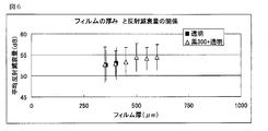
- FIG. 6 is a plot of the relationship between film thickness and return loss.
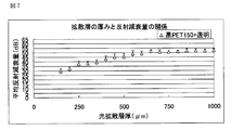
- FIG. 7 is a plot of the relationship between the thickness of the light diffusion layer and the return loss.
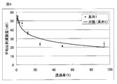
- FIG. 8 is a plot of the relationship between transmittance and return loss.
- FIG. 1 shows a schematic configuration diagram of the optical termination film of the present invention.
- the light termination film 1 of the present invention has a light diffusion layer 11 for diffusing light and a light absorption layer 13 for absorbing light.
- the optical termination film which concerns on this invention has the structure which concerns on the combination of two layers of a light-diffusion layer and a light absorption layer, and can obtain the optical termination film which shows a high amount of return loss.
- the optical termination film of the present invention can be used as a matching film for reflection measurement used in reflection attenuation measurement.
- the light diffusion layer 11 is made of a transparent resin and is used in contact with the optical connector, and has a role of taking in and diffusing light into the layer.
- the said light-diffusion layer 11 is located in the outermost layer in the optical termination film of this invention, and has the optical connector pressing surface 111 by which the surface was formed in the plane. Since the pressing surface is formed as a flat surface, connection loss is reduced even when the connector end surface is a flat surface.
- the light diffusion layer is made of a resin having a refractive index of 1.35 to 1.55.
- the refractive index is more preferably 1.40 to 1.50.
- the refractive index preferably has a refractive index matching with the core of the optical fiber.
- the refractive index can be adjusted based on well-known techniques such as resin blending.
- the refractive index is measured according to JIS K7142.
- the resin is a polymer material such as acrylic, epoxy, vinyl, silicone, rubber, urethane, methacryl, nylon, bisphenol, diol, polyimide, fluorinated epoxy, fluorine
- polymers such as fluorinated acrylics.
- acrylic polymers and silicone polymers are particularly preferably used.
- the resin used has adhesiveness.
- the adhesive strength is preferably 1 to 100 gf / 25 mm, more preferably 5 to 50 gf / 25 mm, and further preferably 10 to 30 gf / 25 mm.
- adhesive force can be suitably adjusted with the combination, compounding quantity, etc. of an adhesive and a hardening
- said adhesive force is the value measured based on 180 degree peeling adhesive force of JISZ0237.
- a known light diffusing agent can be added to the light diffusing layer as long as it does not cause return light.
- translucent fine particles such as an acrylic resin filler and a silica filler may be contained.
- the thickness of the light diffusion layer is preferably 10 ⁇ m or more, more preferably 50 ⁇ m or more, and further preferably 100 ⁇ m or more. If it is 10 ⁇ m or more, it is possible to secure a sufficient optical path for diffusing light in the light diffusion layer of the present invention. Further, since the reflection attenuation amount increases by increasing the thickness of the light diffusion layer, the thickness can be changed as appropriate. In particular, when the thickness is 700 ⁇ m or more, the effect of light diffusion can be maximized, so that a film having a particularly high return loss can be obtained. Further, as the thickness is increased, the variation in the return loss is reduced because the structure is stable. Although an upper limit is not specifically limited, Since the return loss amount by light diffusion is saturated, 750 micrometers is mentioned from a viewpoint of manufacturing cost, for example.
- the light absorption layer 13 absorbs the light that has entered and diffused into the light diffusion layer.
- the light absorption layer 13 is preferably provided adjacent to the light diffusion layer 11.
- the light absorption layer includes a resin and a colorant that absorbs light. That is, light that has passed through the light diffusion layer enters the light absorption layer and is absorbed by the colored substance.
- the light absorption layer is made of a resin having a refractive index of 1.35 to 1.55.
- the refractive index is more preferably 1.40 to 1.50. It is preferable that the refractive index of the light absorption layer has consistency with the refractive index of the resin of the light diffusion layer, the refractive index of the resin forming the light diffusion layer, and the refraction of the resin of the light absorption layer.
- the difference in rate is preferably within a range of ⁇ 0.1, and more preferably within a range of ⁇ 0.05. In this manner, by matching the refractive index of the resin at the interface between the light diffusion layer and the light absorption layer, reflection at these interfaces can be prevented, so that a high light attenuation can be obtained.
- the refractive index of the light absorption layer is also measured according to JIS K 7142, and the measurement is performed with a resin that does not contain the colorant of the light absorption layer.
- the resin for the light absorption layer those exemplified as the resin for the light diffusion layer can be used. However, it is preferable to select the same resin as that used for the light diffusion layer from the viewpoint of increasing the light attenuation.
- the light transmittance of the light absorbing layer is preferably 10% or less, more preferably 5% or less, and even more preferably 2% or less.
- the lower limit of the light transmittance is not particularly limited, but is, for example, 0.1%. By setting the transmittance in such a range, a high return loss can be obtained.
- the range of the light transmittance can be adjusted by selecting the type and content of the colorant, the thickness of the light absorption layer, and the like.
- the light transmittance means the light transmittance of 1310 nm, and details are shown in the Examples.
- the colorant is not particularly limited as long as it can absorb light passing through the optical fiber, and may be a pigment or a dye.
- the colorant is preferably a black colorant considering the ease of light absorption. More specifically, examples of the colorant include carbon black and phthalocyanine blue.
- the content of the colorant is not particularly limited, but is preferably 0.1 to 10% by weight and more preferably 0.1 to 5% by weight with respect to the resin of the light absorption layer.
- the thickness of the light absorption layer can be appropriately changed according to the light absorption performance such as the content of the colorant and the ease of handling of the photo-termination film. For example, it is preferably 10 ⁇ m or more. 50 ⁇ m or more is more preferable, and 100 ⁇ m or more is more preferable. In particular, when the thickness is 200 ⁇ m or more, the light absorption effect can be maximized, so that a film exhibiting a particularly high return loss can be obtained. Although an upper limit is not specifically limited, Since the return loss amount by light absorption is saturated, 300 micrometers is mentioned from a viewpoint of manufacturing cost, for example.
- the light termination film of the present invention can be produced by a known method.
- the light termination film can be formed by applying a paint for forming the light absorption layer on the layer. .
- the minimum return loss of the optical termination film of the present invention is preferably 40 dB or more and more preferably 50 dB or more when the wavelength is 1310 nm in the single mode. Although an upper limit is not specifically limited, For example, it is 65 dB.
- the return loss can be adjusted by changing the transmittance of the light absorption layer and the thickness ratio between the light diffusion layer and the light absorption layer.
- the minimum return loss means the lowest value among the values measured a plurality of times by a return loss measurement device (reflection meter RM3750 + 1FA7 manufactured by JDS Uniphase).
- the total thickness of the optical termination film of the present invention is not particularly limited, but is preferably 20 to 1500 ⁇ m, more preferably 200 to 1000 ⁇ m, and still more preferably 300 to 700 ⁇ m. By setting it as the thickness of the said range, it becomes easy to handle as a film.
- the optical termination film of the present invention may be used as it is in contact with the end face of the optical connector, but it is preferable to use a reflection measuring jig to facilitate contact with the optical connector.
- FIG. 2 is a schematic configuration diagram of the reflection measurement jig.
- FIG. 3 is an exploded view of the reflection measurement jig.
- the reflection measuring jig includes a light termination film 1 according to the present invention, a base substrate 2 on which the light termination film is attached, a connector guide plate 3 for contacting the light termination film and the optical connector, Have
- the optical termination film 1 is disposed on the upper surface of the base substrate 2.
- the film is attached to the substrate via an adhesive so that the light diffusion layer 11 is the upper surface and the light absorption layer 13 is the lower surface.
- a plurality of optical termination films may be provided.
- the connector guide plate 3 has a guide hole 31 in which the optical termination film 1 provided on the base substrate 2 is accommodated and has a width that matches at least one side of the optical connector.
- the optical connector include an MT connector (JIS C 5981 / IEC 61754-5), an MPO connector (JIS C5982 / IEC 61754-7), and other multi-fiber connectors having a flat end surface.
- the base substrate 2 and the connector guide plate 3 are bonded together, and the optical termination film 1 and the base substrate 2 are bonded together in the guide hole 31 of the connector guide plate 3 to constitute a reflection measurement jig.
- the guide hole 31 is provided in a number corresponding to the number of films 1 provided on the base substrate.
- the reflection attenuation can be measured by pressing the optical connector against the film 1 from the guide hole of the reflection measurement jig. At this time, by pressing through the guide hole, the optical connector and the film are optically well connected, and a high light attenuation can be obtained.
- Refractive index is a value measured with an Abbe refractometer 2T type (manufactured by Atago Co., Ltd.) according to JIS K 7142 (hereinafter referred to as other materials). Refractive index is also measured in the same way)).
- Material X Acrylic adhesive ⁇ (100 parts by weight) + epoxy curing agent (4 parts by weight), adhesive strength 30 gf / 25 mm, refractive index 1.468 at 20 ° C.
- Black PET film A light-shielding optical inspection film comprising a PET resin substrate, a refractive index of 1.58 at 20 ° C. of PET resin
- the black PET film having a thickness of 50 ⁇ m was laid, the material X was applied thereon, and a light diffusing layer having a thickness of 50 ⁇ m shown in Table 1 was laminated to produce a photo-termination film.
- a light-termination film was prepared by laminating a light-absorbing layer of 100 ⁇ m composed of material X mixed with black pigment on a light-diffusing layer of 1000 ⁇ m composed of material X.
- a 12-core quartz single-mode optical fiber ribbon manufactured by Sumitomo Electric Co., Ltd., outer diameter 0.25 mm ⁇ , refractive index 1.452 at 20 ° C.
- An SC connector was attached and the other end was subjected to MT connector processing.
- the SC connector side was connected to a reflection attenuation measuring device (reflection meter RM3750 + 1FA7 manufactured by JDS Uniphase), the MT connector was pressed against the above-mentioned optical termination film, and the reflection attenuation was measured at a single mode wavelength of 1310 nm.
- the numerical values of the 12 cores are equal to each other below, the numerical value of the 6th core wire is described as a representative value.
- Table 1 shows the measurement results of the return loss.
- FIG. 4 shows a plot of the relationship between the thickness of the light diffusion layer and the return loss. From these results, it was found that the return loss tends to increase as the thickness of the light diffusion layer increases. However, the maximum return loss hardly increased when the thickness of the light diffusion layer was 700 ⁇ m or more. Even when the thickness was 700 ⁇ m or more, it was found that the minimum return loss gradually increased as the thickness increased. However, even when the thickness was 1000 ⁇ m, the minimum value was 42.2 dB, and the minimum value was 50 dB. I knew it would not reach. In Example 1, by providing a light absorption layer obtained by adding a black pigment to a resin having the same composition as the resin of the light diffusion layer, the minimum return loss is 52.2 dB, which is a value much higher than the above reference example. showed that.
- a light termination film having only a light absorbing layer was prepared.
- the above PET film having a thickness of 50 ⁇ m is laid, and a material Y obtained by adding 0.39% by weight of a black pigment (carbon black) to the material X used in Reference Examples 1 to 20 is applied as a resin for the light absorption layer.
- a light-termination film was prepared by laminating a light absorption layer having a film thickness shown in Table 2 (the refractive index of the resin of the material X and the material Y is the same value).
- Example 2 Reference Example 30
- a light termination film having a film thickness according to Table 3 was prepared (Example 2).
- a photo-termination film was prepared using only the material Y (Reference Example 30).
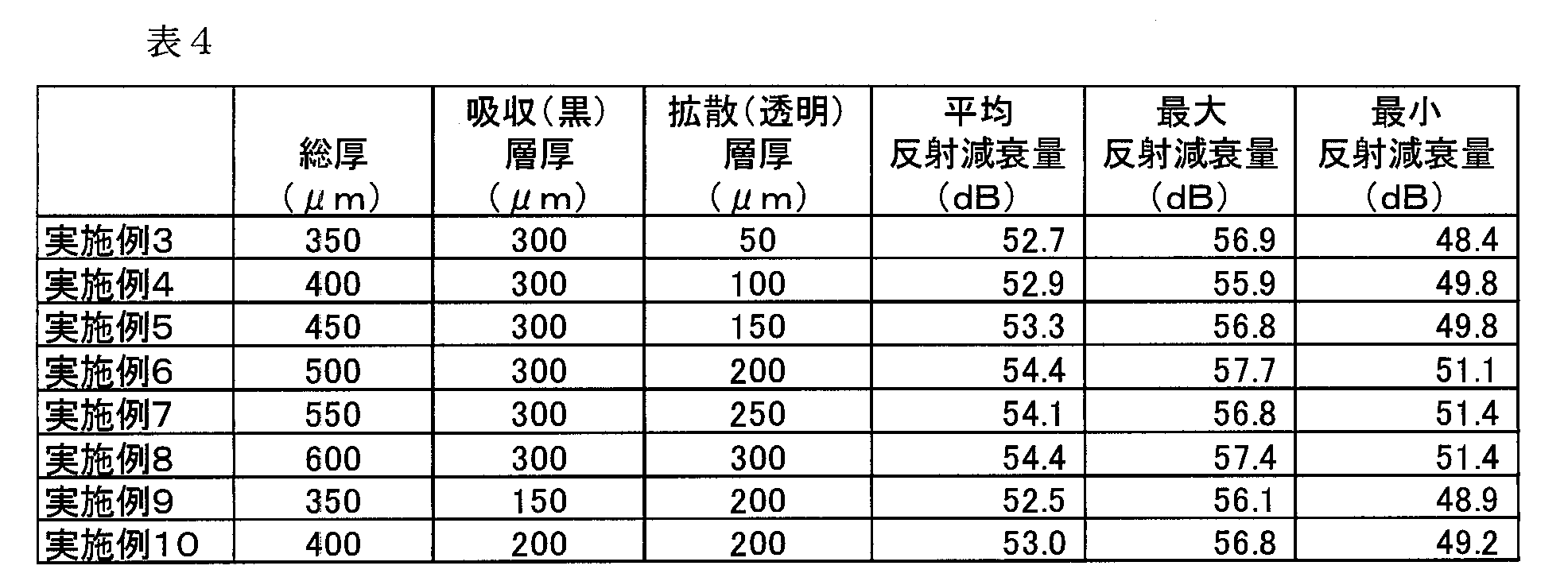
- Examples 3 to 10 A phototermination film was prepared in the same manner as in Example 2 except that the thickness of each layer was changed to the thickness shown in Table 4. The reflection loss was measured for these optical termination films, and the results are shown in Table 4.
- FIG. 6 shows the relationship between the thickness of the film and the return loss (Examples 3 to 8 are “black 300 + transparent”, and “transparent” is a reference example). From the results, it was found that a high return loss can be obtained by matching the refractive indexes of the light diffusion layer and the light absorption layer in the combination of the light diffusion layer and the light absorption layer.
- Acrylic adhesive for optical use product name: KP-2254B, manufactured by Nippon Carbide Co., Ltd., refractive index: 1.478
- black dye product name: Black S-BL, manufactured by Sumika Chemtex Co., Ltd.
- a black pressure-sensitive adhesive was prepared by adding 4.5 parts by mass to 100 parts by mass and agitating with a disper (stirrer) for 20 minutes.
- a light termination film having a light diffusion layer was prepared.
- FIG. 8 is a graph plotting the relationship between transmittance and return loss. The transmittance was measured with 1310 nm light using UV-3100 manufactured by Shimadzu Corporation under the conditions shown in Table 7. From this experiment, it was found that there is a relationship between transmittance and return loss.
- ABS resin ABS resin (refractive index 1.51 at 20 ° C.) and carbon black are mixed.
- SUS Stainless steel
- the present invention is used as a termination material in the measurement of return loss.
- Light termination film 11 Light diffusion layer 13: Light absorption layer 2: Base substrate 3: Connector guide plate 31: Guide hole
Landscapes
- Physics & Mathematics (AREA)
- General Physics & Mathematics (AREA)
- Optics & Photonics (AREA)
- Optical Elements Other Than Lenses (AREA)
- Testing Of Optical Devices Or Fibers (AREA)
- Mechanical Coupling Of Light Guides (AREA)
Abstract
【課題】 接触端面が平面のコネクタであっても、接続損失が少ない光終端材料の提供。 【解決手段】 屈折率1.35~1.55の樹脂を含み、最表層に位置し、その表面が平面に形成されたコネクタ押当面を有する、光を拡散させるための光拡散層と、屈折率1.35~1.55の樹脂と、光を吸収ための着色料とを含む、光吸収層と、を有し、前記光拡散層を形成する樹脂の屈折率と、前記光吸収層の樹脂の屈折率の差が、±0.1の範囲内である、光終端フィルム。
Description
本発明は、光ファイバと接続して光を減衰させる光終端材料に関し、特に反射測定に用いられる光終端材料に関する。
光ファイバ先端にコネクタ加工を施した場合や、融着などによってファイバ同士を接続した後に、その加工状態や接続状態を確認するため等の目的で反射減衰量の測定が行なわれる。反射減衰量を測定する際に、光コネクタ等の終端にマッチングブロックを押し当てて、光ファイバ内の光を終端から外に放出して、無反射に近い状態にし、接続部の反射減衰量測定を行う。この際、使用されるマッチングブロックとしては、円柱状の浅底容器に光ファイバのコアと屈折率を整合させた樹脂が充填され、その底部には入射した光を入射方向とは異なる方向へと反射させるための傾斜が設けられたものが使用されている(例えば、三和電気工業社製、製品名:反射測定用マッチングブロック)。このようなマッチングブロックを使用することによって、終端に高い反射減衰量が得られる。
反射測定用マッチングブロックに関しては、ほとんど技術報告がなされていないが、光ファイバの末端と接続して高い減衰量を得るための光終端器や、光減衰器に関する報告がされている。特許文献1には、粘着性屈折率整合剤のみからなる光終端器が開示されている。特許文献2には、光通信用光吸収膜としてカーボンブラックが分散された高分子膜が用いられることが記載されている。特許文献3には、光吸収層を光拡散部材の周囲に設けた終端器が開示されている。
上記のマッチングブロックにおいては、円柱状の容器の中に液体の状態の樹脂を充填するため、その界面張力によって樹脂容器と液との接触部分が盛り上がり、その表面がなだらかな凹状の曲面(メニスカス)となってしまう。この場合、LC(IEC 61754‐20)やMU(JIS C 5983(F14)/IEC 61754‐6)コネクタ等のように接続端部のフェルール端面が凸状湾曲しているものとの接触においては問題が発生しにくい。しかし、MTコネクタ(JIS C 5981(F12)/IEC 61754-5)や、MPOコネクタ(JIS C5982(F13)/IEC61754-7)等のように接続端面が平面の場合には、マッチングブロックの表面が曲面状であるとコネクタ端面とマッチングブロックの接触界面の一部に空気層ができ、接続損失が発生してしまう。特に多心タイプのコネクタを使用する場合には、マッチングブロックと確実に接触させることは困難である。そして、計測の都度、接続端面をマッチングブロックのコネクタ接触端面に押付ける必要があり、押付け方によって各心線の光減衰量測定値に差がでる可能性がある。また、上記マッチングブロックや屈折率整合粘着剤、接着剤等に黒色顔料等の光学吸収特性を有する材料を添加させて、吸収層としてコネクタ端面と直接接触させて使用した場合は、そのファイバとの屈折率差や、高分子フィラーの介在で戻り光が起きる可能性があり、高い光終端特性や、光学反射安定性は得られない。
本発明は、このような課題を解決するため、接触端面が平面のコネクタであっても、接続損失が少ない光終端材料を提供することを目的とする。
本発明は上記の課題の下、鋭意研究の結果、表面が平面となるフィルム形状とすることによって、平面の端面を有するコネクタとの接続損失を低減させることができることに着目し、更に、フィルムの構成を光拡散層と、光吸収層の二層の構成を有することによって高い光減衰量を実現することができることを見出した。
すなわち、本発明(1)は、屈折率1.35~1.55の樹脂を含み、最表層に位置し、その表面が平面に形成されたコネクタ押当面を有する、光を拡散させるための光拡散層と、
屈折率1.35~1.55の樹脂と、光を吸収するための着色料とを含む、光吸収層と、
を有し、前記光拡散層を形成する樹脂の屈折率と、前記光吸収層の樹脂の屈折率の差が、±0.1の範囲内である、光終端フィルムである。
屈折率1.35~1.55の樹脂と、光を吸収するための着色料とを含む、光吸収層と、
を有し、前記光拡散層を形成する樹脂の屈折率と、前記光吸収層の樹脂の屈折率の差が、±0.1の範囲内である、光終端フィルムである。
本発明(2)は、前記光拡散層の厚みが、10μm以上である、前記発明(1)の光終端フィルムである。
本発明(3)は、前記光吸収層の光透過率が、10%以下である、前記発明(1)又は(2)の光終端フィルムである。
本発明(4)は、前記光吸収層の着色料の含有量が、0.1~10重量%である、前記発明(1)~(3)のいずれか一つの光終端フィルムである。
本発明(5)は、前記光拡散層が、1~100gf/25mmの弱粘着性を有する、前記発明(1)~(4)のいずれか一つの光終端フィルムである。
本発明(6)は、前記発明(1)~(5)のいずれか一つの光終端フィルムからなる、反射測定用マッチングフィルムである。
本発明(7)は、光を拡散させるための光拡散層(例えば、光拡散層11)と、光を吸収するための光吸収層(例えば、光吸収層13)とを有する、光終端フィルム(例えば、光終端フィルム1)と、
前記光終端フィルムが表面に取り付けられたベース基板(例えば、ベース基板2)と、
前記光終端フィルムと光コネクタとを当接するためのコネクタガイド(例えば、コネクタガイド3)と、を有する反射測定用治具である。
前記光終端フィルムが表面に取り付けられたベース基板(例えば、ベース基板2)と、
前記光終端フィルムと光コネクタとを当接するためのコネクタガイド(例えば、コネクタガイド3)と、を有する反射測定用治具である。
本発明によれば、接触端面が平面のコネクタとの接続損失が少なく、更に、高い光減衰量が得られる光終端材料となる。またコネクタとフィルムを接触させて光拡散層から光を入射させることによって光拡散層中で光が拡散される。拡散された光は、光吸収層へと入射して吸収される。更に、光拡散層と光吸収層の屈折率の差を±0.1の範囲内とすることでこれらの層の界面における反射が少なくなり、戻り光を防止することができる。このように光拡散層と光吸収層とを組み合わせて使用すること、更には、これらの層の屈折率を整合させることによって、フィルム形状のように長い拡散光路を確保できないような形状であっても高い反射減衰量が得られる。尚、本発明に係る光終端フィルムは、シングルモード及びマルチモードの光伝送媒体いずれにも適用できる。
図1は、本発明の光終端フィルムの概略構成図を示す。本発明の光終端フィルム1は、光を拡散させるための光拡散層11と、光を吸収するための光吸収層13とを有する。このように本発明に係る光終端フィルムは、光拡散層と、光吸収層との二層の組合せに係る構成を有することによって、高い反射減衰量を示す光終端フィルムが得られる。本発明の光終端フィルムは、反射減衰測定において用いられる反射測定用マッチングフィルムとして使用することができる。
(光拡散層)
光拡散層11は、透明性の樹脂からなり、光コネクタと当接して使用されて当該層内に光を取り込み拡散させる役割を有する。当該光拡散層11は、本発明の光終端フィルム中、最表層に位置し、その表面が平面に形成された光コネクタ押当面111を有する。当該押当面は、平面に形成されていることによって、コネクタ端面が平面であるものを用いた場合であっても接続損失が少なくなる。
光拡散層11は、透明性の樹脂からなり、光コネクタと当接して使用されて当該層内に光を取り込み拡散させる役割を有する。当該光拡散層11は、本発明の光終端フィルム中、最表層に位置し、その表面が平面に形成された光コネクタ押当面111を有する。当該押当面は、平面に形成されていることによって、コネクタ端面が平面であるものを用いた場合であっても接続損失が少なくなる。
光拡散層は、屈折率1.35~1.55の樹脂からなる。当該屈折率は、1.40~1.50がより好適である。屈折率は、光ファイバのコアとの屈折率の整合性を有していることが好適である。屈折率は樹脂の配合等、周知技術に基づいて調節可能である。屈折率は、JIS K 7142に準じて測定する。
ここで、樹脂は、高分子材料、例えばアクリル系、エポキシ系、ビニル系、シリコーン系、ゴム系、ウレタン系、メタクリル系、ナイロン系、ビスフェノール系、ジオール系、ポリイミド系、フッ素化エポキシ系、フッ素化アクリル系等のポリマーを含む。また必要に応じてこれらを混合したり、フッ素樹脂や硬化剤を加えたりして用いることができる。これらの樹脂の中でも、アクリル系ポリマーとシリコーン系ポリマーが特に好ましく使用される。
尚、使用される樹脂は、粘着性を有することが好適である。その際、粘着力は1~100gf/25mmが好適であり、5~50gf/25mmがより好適であり、10~30gf/25mmが更に好適である。このような範囲の粘着力を有することによって、光コネクタとの接続が安定し、剥離が容易になる。そして、粘着力は、粘着剤と硬化剤の組み合わせや配合量等によって適宜調節することができる。なお、上記の粘着力は、JIS Z 0237の180度引きはがし粘着力に準拠して測定した値である。
また、光拡散層には、戻り光の要因とならなければ公知の光拡散剤を添加することができ、例えば、アクリル樹脂フィラー、シリカフィラーなどの透光性微粒子を含有させてもよい。
光拡散層の厚みは、10μm以上が好適であり、50μm以上がより好適であり、100μm以上が更に好適である。10μm以上であれば、本発明の光拡散層において光を拡散するのに十分な光路を確保することができる。また、光拡散層の厚みを増すことによって、反射減衰量が増加するため、当該厚さを適宜変更することができる。特に700μm以上であることによって、光拡散の効果を最大限に発揮することができるため、特に高い反射減衰量を示すフィルムが得られる。また厚みが増すと構造上安定するために、反射減衰量のばらつきが小さくなる。上限は特に限定されないが、光拡散による反射減衰量が飽和するため、製造コストの観点から例えば750μmが挙げられる。
(光吸収層)
光吸収層13は、光拡散層に入射されて拡散された光を吸収する。光吸収層13は、当該光拡散層11と隣接して設けられることが好適である。光吸収層は、樹脂と光を吸収する着色料とを含む。すなわち、光拡散層を通過した光が光吸収層に入射して、着色した物質によって光を吸収する。
光吸収層13は、光拡散層に入射されて拡散された光を吸収する。光吸収層13は、当該光拡散層11と隣接して設けられることが好適である。光吸収層は、樹脂と光を吸収する着色料とを含む。すなわち、光拡散層を通過した光が光吸収層に入射して、着色した物質によって光を吸収する。
光吸収層は、屈折率1.35~1.55の樹脂からなる。当該屈折率は、1.40~1.50がより好適である。光吸収層の屈折率は、光拡散層の樹脂との屈折率の整合性を有していることが好適であり、光拡散層を形成する樹脂の屈折率と、光吸収層の樹脂の屈折率の差が、±0.1の範囲内であることが好適であり、±0.05の範囲内であることがより好適である。このようにして、光拡散層と光吸収層の界面における樹脂の屈折率を整合させることで、これらの界面での反射を防ぐことができるため、高い光減衰量を得ることができる。光吸収層の屈折率もJIS K 7142に準じて測定し、光吸収層の着色料を含まない樹脂で測定を行う。
光吸収層の樹脂は、光拡散層の樹脂として例示したものが使用できるが、光拡散層で用いた樹脂と同一の樹脂を選択することが、光減衰量を高める観点から好適である。
光吸収層の光透過率は、10%以下であることが好適であり、より好適には5%以下であり、更に好適には2%以下である。光透過率の下限値は、特に限定されないが、例えば、0.1%である。このような範囲の透過率とすることによって、高い反射減衰量を得ることができる。なお、光透過率の範囲は、着色料の種類、含有量や、光吸収層の厚み等の選択によって調整可能である。光透過率は、1310nmの光の透過率を意味し、詳細は実施例に示す。
着色料は、光ファイバから通過する光を吸収可能であれば特に限定されず、顔料であっても染料であってもよい。着色料としては、光の吸収のし易さを考慮すると黒色の着色料であることが好適である。より具体的に着色料としては、例えば、カーボンブラック、フタロシアニンブルーが挙げられる。
着色料の含有量は、特に限定されないが、光吸収層の樹脂に対して、0.1~10重量%が好適であり、0.1~5重量%がより好適である。
光吸収層の厚みは、着色料の含有量等の光吸収性能や、光終端フィルムの取扱のし易さに応じて、適宜変更することが可能であるが、例えば、10μm以上が好適であり、50μm以上がより好適であり、100μm以上が更に好適である。特に200μm以上であることによって、光吸収効果を最大限に発揮することができるため、特に高い反射減衰量を示すフィルムが得られる。上限は特に限定されないが、光吸収による反射減衰量が飽和するため、製造コストの観点から例えば、300μmが挙げられる。
本発明の光終端フィルムは、公知の方法により製造することができるが、例えば、光吸収層を形成した後に、当該層の上に光吸収層を形成する塗料を塗布して形成することができる。
本発明の光終端フィルムの最小反射減衰量は、シングルモードで波長1310nmのときに40dB以上が好適であり、50dB以上がより好適である。上限は特に限定されないが例えば、65dBである。反射減衰量は、光吸収層の透過率と、光拡散層と光吸収層の厚み比を変更することによって調整可能である。ここで、最小反射減衰量は、反射減衰量測定装置(JDSUniphase製 リフレクションメータ RM3750+1FA7)により複数回測定した値のうち最も低い値を意味する。
本発明の光終端フィルムの総厚は、特に限定されないが、20~1500μmが好適であり、200~1000μmがより好適であり、300~700μmが更に好適である。当該範囲の厚みとすることにより、フィルムとして取扱がし易くなる。
本発明の光終端フィルムは、そのまま光コネクタの端面と当接して使用してもよいが、反射測定用治具を用いて光コネクタとの当接をし易くすることが好適である。図2は、反射測定用治具の概略構成図である。図3は、反射測定用治具の分解図である。反射測定治具は、本発明に係る光終端フィルム1と、当該光終端フィルムが表面に取り付けられたベース基板2と、前記光終端フィルムと光コネクタとを当接するためのコネクタガイド板3と、を有する。
図3に示すように、ベース基板2の上面に光終端フィルム1が配される。当該フィルムは、光拡散層11が上面、光吸収層13が下面になるようにして、当該基板上に接着剤を介して貼り付けられる。光終端フィルムは、複数設けられていてもよい。
コネクタガイド板3は、ベース基板2の上に設けた光終端フィルム1が収まり、光コネクタの少なくとも一辺と合致する幅を有するガイド孔31を有している。ここで、光コネクタとしては、MTコネクタ(JIS C 5981/IEC 61754-5)や、MPOコネクタ(JIS C5982/IEC61754-7)等の端面が平面である多心コネクタが挙げられる。
ベース基板2と、コネクタガイド板3を張り合わせて、コネクタガイド板3のガイド孔31内で、光終端フィルム1とベース基板2とを張り合わせて、反射測定用治具が構成される。ガイド孔31は、ベース基板上に設けるフィルム1の枚数に対応する数が設けられる。
反射測定用治具のガイド孔から、光コネクタをフィルム1に押し当てて、反射減衰量を測定することができる。この際、ガイド孔を介して押し当てることによって、光コネクタとフィルムが光学的に良好に接続された状態となり、高い光減衰量を得ることができる。
<参考例1~20>
光終端フィルムを作成した。
光拡散層の樹脂として、以下の材料Xを用意した(屈折率は、JIS K 7142に準じて、アッベ屈折率計2T型(株式会社アタゴ製)にて測定した値である(以下、その他の屈折率も同様の測定方法)。)。
光終端フィルムを作成した。
光拡散層の樹脂として、以下の材料Xを用意した(屈折率は、JIS K 7142に準じて、アッベ屈折率計2T型(株式会社アタゴ製)にて測定した値である(以下、その他の屈折率も同様の測定方法)。)。
材料X:
アクリル系粘着剤α(100重量部)+エポキシ系硬化剤(4重量部)、粘着力30gf/25mm、20℃での屈折率1.468
アクリル系粘着剤α(100重量部)+エポキシ系硬化剤(4重量部)、粘着力30gf/25mm、20℃での屈折率1.468
また、光吸収層として以下の黒色のPETフィルムを用いた。
黒色PETフィルム:
PET樹脂基材からなる遮光性の光学用検査フィルム、PET樹脂の20℃での屈折率1.58
PET樹脂基材からなる遮光性の光学用検査フィルム、PET樹脂の20℃での屈折率1.58
厚さ50μmの上記黒色PETフィルムを敷き、その上に材料Xを塗布して、表1記載の50μmの厚みの光拡散層を積層して光終端フィルムを作成した。
<実施例1>
材料Xから構成される1000μmの光拡散層に対して、黒色顔料を混合した材料Xから構成される100μmの光吸収層を積層して光終端フィルムを作成した。
材料Xから構成される1000μmの光拡散層に対して、黒色顔料を混合した材料Xから構成される100μmの光吸収層を積層して光終端フィルムを作成した。
(反射減衰量の測定方法)
光反射測定には、12心石英系シングルモードの光ファイバテープ心線(住友電工社製、外径0.25mmφ、20℃での屈折率1.452)に片端ファンアウト配線にして8本のSCコネクタを取付、他端にMTコネクタ加工を施したものを用いた。SCコネクタ側は反射減衰量測定装置(JDSUniphase製 リフレクションメータ RM3750+1FA7)に接続し、MTコネクタを上記の光終端フィルムに押し当てて、シングルモードの波長1310nmにて反射減衰量を測定した。なお、以下測定数値は12心各数値が同等であったため、代表値として6番心線の数値を記載することとする。
光反射測定には、12心石英系シングルモードの光ファイバテープ心線(住友電工社製、外径0.25mmφ、20℃での屈折率1.452)に片端ファンアウト配線にして8本のSCコネクタを取付、他端にMTコネクタ加工を施したものを用いた。SCコネクタ側は反射減衰量測定装置(JDSUniphase製 リフレクションメータ RM3750+1FA7)に接続し、MTコネクタを上記の光終端フィルムに押し当てて、シングルモードの波長1310nmにて反射減衰量を測定した。なお、以下測定数値は12心各数値が同等であったため、代表値として6番心線の数値を記載することとする。
反射減衰量の測定結果を表1に示す。また、光拡散層の厚みと反射減衰量の関係をプロットして図4に示す。これらの結果より、光拡散層の厚さが増すと、反射減衰量が高くなる傾向にあることがわかった。但し、光拡散層の厚さが700μm以上となると最大反射減衰量は、ほとんど上昇しなかった。尚、700μm以上であっても、厚みが増すことによって、最小反射減衰量は徐々に高い値を示すことがわかったが、厚さ1000μmでも最低値42.2dBとなり、当該最低値が50dBには到達しないことがわかった。実施例1において、光拡散層の樹脂と同組成の樹脂に黒色顔料を添加した光吸収層を設けることによって、最小反射減衰量が52.2dBを示し、上記の参考例よりもはるかに高い値を示した。

(参考例21~29)
光吸収層のみを有する光終端フィルムを作成した。
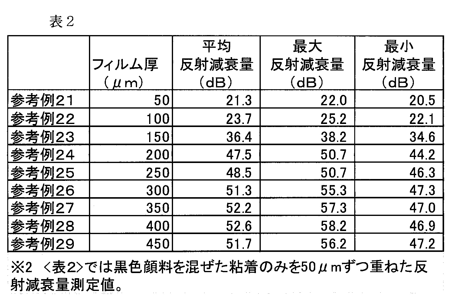
厚さ50μmの上記PETフィルムを敷き、光吸収層の樹脂として、上記参考例1~参考例20において使用した材料Xに、黒色顔料(カーボンブラック)を0.39重量%添加した材料Yを塗布して、表2記載のフィルム厚の光吸収層を積層して光終端フィルムを作成した(材料Xと、材料Yの樹脂の屈折率は同じ値)。
光吸収層のみを有する光終端フィルムを作成した。
厚さ50μmの上記PETフィルムを敷き、光吸収層の樹脂として、上記参考例1~参考例20において使用した材料Xに、黒色顔料(カーボンブラック)を0.39重量%添加した材料Yを塗布して、表2記載のフィルム厚の光吸収層を積層して光終端フィルムを作成した(材料Xと、材料Yの樹脂の屈折率は同じ値)。
上記と同様に反射減衰量を測定した結果を表2に示した。光吸収層の厚みと、反射減衰量の関係をプロットして図5に示した。これらの結果より、光吸収層の厚さが増すと、反射減衰量が高くなる傾向にあることがわかった。但し、光拡散層の厚さが200μm以上となると最大反射減衰量及び最小反射減衰量の上昇率は鈍化した(プロット「黒色」)。なお、上記参考例1~20のうち500μmまでのプロットを「透明」として示し、後述の実施例3~8までのプロットを「黒300+透明」として示した。
(実施例2、参考例30)
光拡散層として上記材料Xを用い、光吸収層として上記材料Y(材料X+黒色顔料)を用いて、表3に係る膜厚の光終端フィルムを作成した(実施例2)。なお、比較として材料Yのみで光終端フィルムを作成した(参考例30)。
光拡散層として上記材料Xを用い、光吸収層として上記材料Y(材料X+黒色顔料)を用いて、表3に係る膜厚の光終端フィルムを作成した(実施例2)。なお、比較として材料Yのみで光終端フィルムを作成した(参考例30)。
これらの光終端フィルムについて反射減衰量を測定し、結果を表3に示した。当該結果より、同じフィルム厚において、光拡散層と、光吸収層を組み合わせることによって、高い反射減衰量が得られることがわかった(特に最小反射減衰量)。

(実施例3~10)
各層の厚みを表4に示した厚みに変更した以外は実施例2と同様にして、光終端フィルムを作成した。これらの光終端フィルムについて反射減衰量を測定し、結果を表4に示した。図6にフィルムの厚みと反射減衰量の関係を示した(実施例3~8は「黒300+透明」、「透明」は参考例)。当該結果より、光拡散層と、光吸収層を組み合わせにおいて、光拡散層と光吸収層の屈折率を整合させることによって、高い反射減衰量が得られることがわかった。
各層の厚みを表4に示した厚みに変更した以外は実施例2と同様にして、光終端フィルムを作成した。これらの光終端フィルムについて反射減衰量を測定し、結果を表4に示した。図6にフィルムの厚みと反射減衰量の関係を示した(実施例3~8は「黒300+透明」、「透明」は参考例)。当該結果より、光拡散層と、光吸収層を組み合わせにおいて、光拡散層と光吸収層の屈折率を整合させることによって、高い反射減衰量が得られることがわかった。
(参考例31~49)
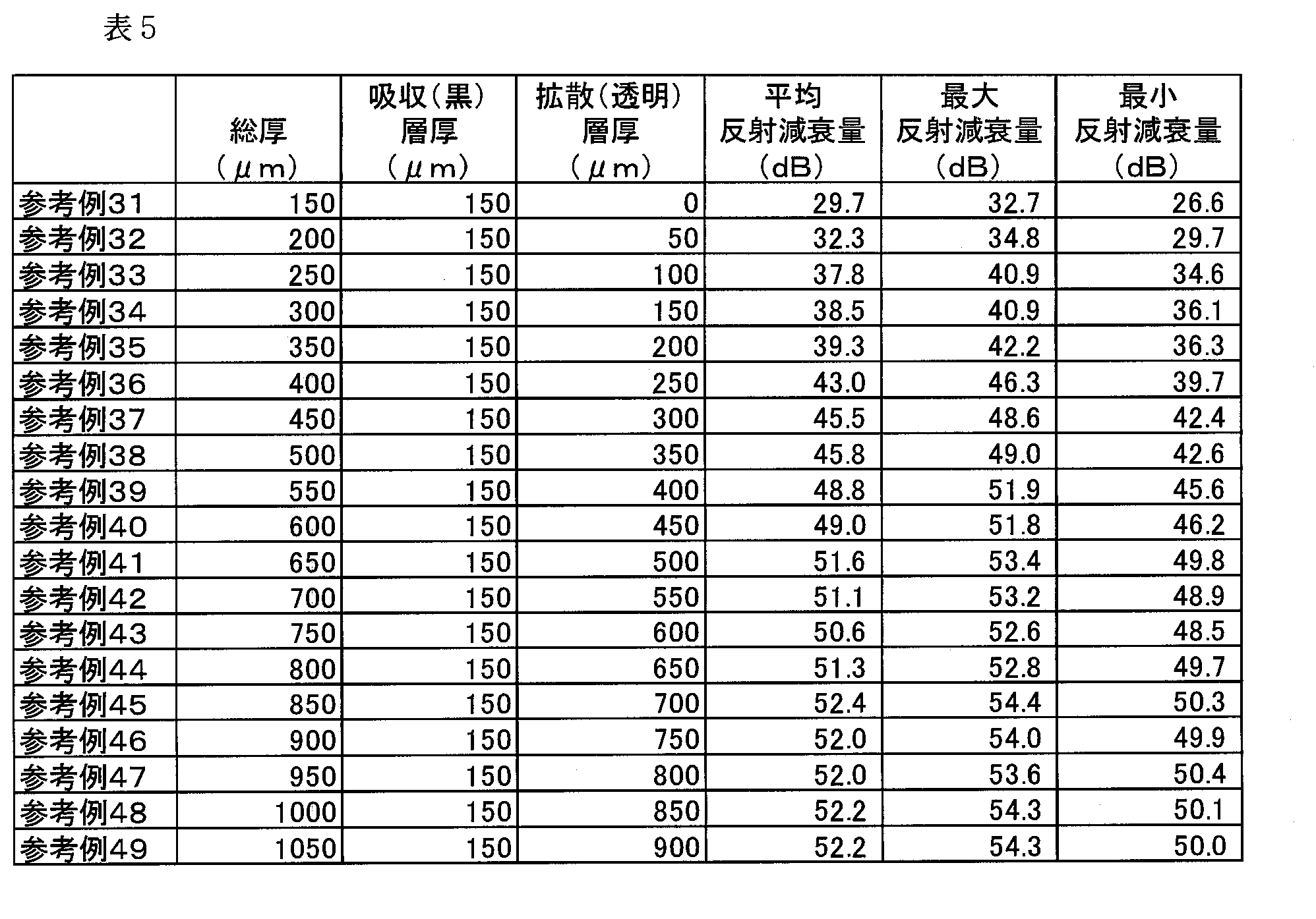
光学用途アクリル系粘着剤(製品名:KP-2254B、日本カーバイト社製、屈折率1.48)に、黒色染料(製品名:Black S-BL、住化ケムテックス社製)を、粘着剤固形分100質量部に対し4.5質量部添加し、ディスパー(撹拌機)で20分攪拌することにより黒色粘着剤を作製した。光吸収層を130μmの黒色PET11の上に、前記黒色粘着剤により形成した20μmの粘着層(合計150μmのPETフィルム)とした以外は参考例1と同様の条件で以下の表5に記載の厚みの光拡散層を有する光終端フィルムを作成した。
光学用途アクリル系粘着剤(製品名:KP-2254B、日本カーバイト社製、屈折率1.48)に、黒色染料(製品名:Black S-BL、住化ケムテックス社製)を、粘着剤固形分100質量部に対し4.5質量部添加し、ディスパー(撹拌機)で20分攪拌することにより黒色粘着剤を作製した。光吸収層を130μmの黒色PET11の上に、前記黒色粘着剤により形成した20μmの粘着層(合計150μmのPETフィルム)とした以外は参考例1と同様の条件で以下の表5に記載の厚みの光拡散層を有する光終端フィルムを作成した。
上記と同様に反射減衰量を測定した結果を表5に示した。光拡散層の厚みと、反射減衰量の関係をプロットして図7に示した。これらの結果より、光拡散層の厚さが増すと、反射減衰量が高くなる傾向にあることがわかった。但し、光拡散層の厚さが500μm以上となると最大反射減衰量及び最小反射減衰量の上昇率は鈍化した。
(参考例50~57)
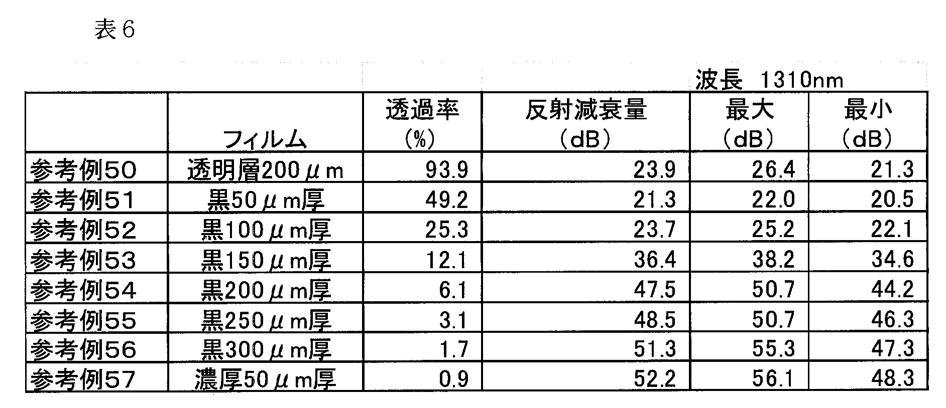
表6に示す単層の光終端フィルムを作成した(参考例51~57)。尚、「透明層」は光拡散層、「黒」は光吸収層、「濃厚」は顔料の含有量を高めた光吸収層、数値は厚さを意味する。これらのフィルムの透過率及び反射減衰量を測定した(表6)。図8は、透過率と反射減衰量の関係をプロットした図である。透過率は、島津製作所社製UV-3100を用いて表7の条件で、1310nmの光にて測定した。当該実験より、透過率と反射減衰量には関係性があることがわかった。
表6に示す単層の光終端フィルムを作成した(参考例51~57)。尚、「透明層」は光拡散層、「黒」は光吸収層、「濃厚」は顔料の含有量を高めた光吸収層、数値は厚さを意味する。これらのフィルムの透過率及び反射減衰量を測定した(表6)。図8は、透過率と反射減衰量の関係をプロットした図である。透過率は、島津製作所社製UV-3100を用いて表7の条件で、1310nmの光にて測定した。当該実験より、透過率と反射減衰量には関係性があることがわかった。

(吸収層の検討:参考例58~59)
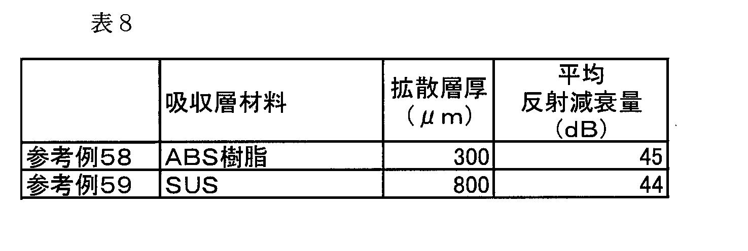
光拡散層としては、材料Xの粘着剤を使用し、光吸収層として、下記の材料を使用して、表8の光終端フィルムを調製し、光減衰量の測定を行った。なお光吸収層の厚みは、拡散層の厚さよりも圧倒的な厚みを有するものを使用した。これらの結果、吸収層に光吸収層と屈折率の整合しない樹脂を用いた場合には、高い反射減衰量が得られないことがわかった。
光拡散層としては、材料Xの粘着剤を使用し、光吸収層として、下記の材料を使用して、表8の光終端フィルムを調製し、光減衰量の測定を行った。なお光吸収層の厚みは、拡散層の厚さよりも圧倒的な厚みを有するものを使用した。これらの結果、吸収層に光吸収層と屈折率の整合しない樹脂を用いた場合には、高い反射減衰量が得られないことがわかった。
ABS樹脂:ABS樹脂(20℃における屈折率1.51)と、カーボンブラックを混合
SUS:ステンレス
SUS:ステンレス
(反復測定試験)
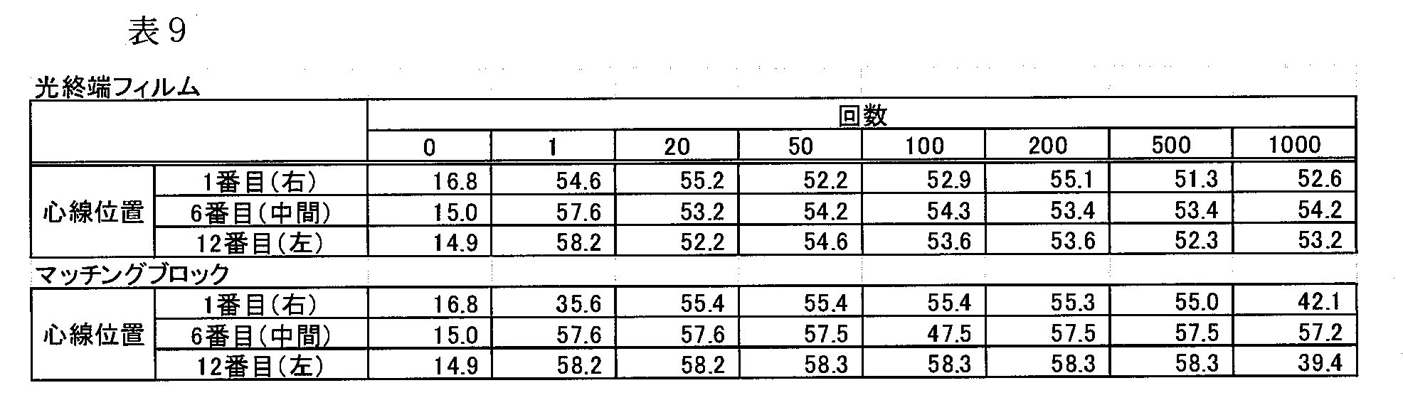
先に示したMTコネクタ(フラット研磨)を用いて、実施例2の光終端フィルム、及び、市販の反射測定用マッチングブロック(三和電気工業社製)で、反射減衰量測定を繰り返し行い反射減衰量の再現性の試験を行なった。12心線のMTコネクタにおける両端及び中間の光ファイバについて反射減衰量を測定して、光終端材料との接触状態を確認した(表9)。結果、市販のマッチングブロックを用いた場合には、測定値にバラツキが現れたが、本発明の光終端フィルムで測定した場合には、バラツキはほとんど現れなかった。
先に示したMTコネクタ(フラット研磨)を用いて、実施例2の光終端フィルム、及び、市販の反射測定用マッチングブロック(三和電気工業社製)で、反射減衰量測定を繰り返し行い反射減衰量の再現性の試験を行なった。12心線のMTコネクタにおける両端及び中間の光ファイバについて反射減衰量を測定して、光終端材料との接触状態を確認した(表9)。結果、市販のマッチングブロックを用いた場合には、測定値にバラツキが現れたが、本発明の光終端フィルムで測定した場合には、バラツキはほとんど現れなかった。
本発明は、反射減衰量の測定において終端材料として使用される。
1 : 光終端フィルム
11 : 光拡散層
13 : 光吸収層
2 : ベース基板
3 : コネクタガイド板
31 : ガイド孔
11 : 光拡散層
13 : 光吸収層
2 : ベース基板
3 : コネクタガイド板
31 : ガイド孔
Claims (7)
- 屈折率1.35~1.55の樹脂を含み、最表層に位置し、その表面が平面に形成されたコネクタ押当面を有する、光を拡散させるための光拡散層と、
屈折率1.35~1.55の樹脂と、光を吸収するための着色料とを含む、光吸収層と、
を有し、前記光拡散層を形成する樹脂の屈折率と、前記光吸収層の樹脂の屈折率の差が、±0.1の範囲内である、光終端フィルム。 - 前記光拡散層の厚みが、10μm以上である、請求項1記載の光終端フィルム。
- 前記光吸収層の光透過率が、10%以下である、請求項1又は2記載の光終端フィルム。
- 前記光吸収層の着色料の含有量が、0.1~10重量%である、請求項1~3のいずれか一項記載の光終端フィルム。
- 前記光拡散層が、1~100gf/25mmの弱粘着性を有する、請求項1~4のいずれか一項記載の光終端フィルム。
- 前記請求項1~5のいずれか一項記載の光終端フィルムからなる、反射測定用マッチングフィルム。
- 光を拡散させるための光拡散層と、光を吸収するための光吸収層とを有する、光終端フィルムと、
前記光終端フィルムが表面に取り付けられたベース基板と、
前記光終端フィルムと光コネクタとを当接するためのコネクタガイドと、を有する反射測定用治具。
Priority Applications (1)
| Application Number | Priority Date | Filing Date | Title |
|---|---|---|---|
| JP2013519469A JP5968312B2 (ja) | 2011-06-09 | 2012-06-01 | 光終端フィルム |
Applications Claiming Priority (2)
| Application Number | Priority Date | Filing Date | Title |
|---|---|---|---|
| JP2011129615 | 2011-06-09 | ||
| JP2011-129615 | 2011-06-09 |
Publications (1)
| Publication Number | Publication Date |
|---|---|
| WO2012169438A1 true WO2012169438A1 (ja) | 2012-12-13 |
Family
ID=47296004
Family Applications (1)
| Application Number | Title | Priority Date | Filing Date |
|---|---|---|---|
| PCT/JP2012/064255 Ceased WO2012169438A1 (ja) | 2011-06-09 | 2012-06-01 | 光終端フィルム |
Country Status (2)
| Country | Link |
|---|---|
| JP (1) | JP5968312B2 (ja) |
| WO (1) | WO2012169438A1 (ja) |
Citations (1)
| Publication number | Priority date | Publication date | Assignee | Title |
|---|---|---|---|---|
| JP2003043264A (ja) * | 2001-07-31 | 2003-02-13 | Yonezawa Densen Kk | 光終端器 |
Family Cites Families (2)
| Publication number | Priority date | Publication date | Assignee | Title |
|---|---|---|---|---|
| JP4765735B2 (ja) * | 2006-04-07 | 2011-09-07 | 日立電線株式会社 | 光終端器 |
| US8842963B2 (en) * | 2010-09-01 | 2014-09-23 | Intuitive Surgical Operations, Inc. | Reducing reflection at termination of optical fiber in a small volume |
-
2012
- 2012-06-01 JP JP2013519469A patent/JP5968312B2/ja not_active Expired - Fee Related
- 2012-06-01 WO PCT/JP2012/064255 patent/WO2012169438A1/ja not_active Ceased
Patent Citations (1)
| Publication number | Priority date | Publication date | Assignee | Title |
|---|---|---|---|---|
| JP2003043264A (ja) * | 2001-07-31 | 2003-02-13 | Yonezawa Densen Kk | 光終端器 |
Also Published As
| Publication number | Publication date |
|---|---|
| JP5968312B2 (ja) | 2016-08-10 |
| JPWO2012169438A1 (ja) | 2015-02-23 |
Similar Documents
| Publication | Publication Date | Title |
|---|---|---|
| KR101546554B1 (ko) | 광 제어 필름 | |
| CN104641268B (zh) | 具有偏振膜的光学叠层体 | |
| CN1277137C (zh) | 光学互连组件及相应方法 | |
| KR101830969B1 (ko) | 고투과 광 제어 필름 | |
| Bilro et al. | Analytical analysis of side-polished plastic optical fiber as curvature and refractive index sensor | |
| CN110692002A (zh) | 光连接器以及光连接器连接结构 | |
| CN102538702A (zh) | 侧掺杂弯曲增敏型光纤曲率传感器 | |
| WO2009153930A1 (ja) | 光伝送媒体、フェルール、光終端コネクタ、光学構造及び光学機器 | |
| US20050205885A1 (en) | Optical waveguide and the method of fabricating the same | |
| WO2017170689A1 (ja) | 光ファイバアレイ | |
| US6623174B2 (en) | Optical connector | |
| US5448667A (en) | Waveguide type optical device with optical receptacles | |
| JP4251853B2 (ja) | 光伝送構造体、および、光導波路の形成方法 | |
| JP5968312B2 (ja) | 光終端フィルム | |
| JP5150201B2 (ja) | 粘着性接続部材およびそれを用いた光学接続構造 | |
| JP2007093647A (ja) | 光学接続構造及び光学接続方法 | |
| JP2004226438A (ja) | 光伝送部品の接続構造および光学接続方法 | |
| Uddin et al. | Delamination problems of UV-cured adhesive bonded optical fiber in V-groove for photonic packaging | |
| JP2010191234A (ja) | 光吸収材、光吸収材貼着治具および光減衰器 | |
| US20090040508A1 (en) | Light Monitoring Method and Light Monitoring Apparatus | |
| US20240126020A1 (en) | Signal light transmission member | |
| JP2008033129A (ja) | 屈折率整合膜の形成方法並びに光ファイバ及び光コネクタ | |
| RU2801081C1 (ru) | Древовидный оптический разветвитель без потерь на обратном отражении и с нулевыми коэффициентами передачи и направленности для волоконно-оптических систем связи | |
| JPH05249447A (ja) | 光ファイバ変調器 | |
| JP2014125405A (ja) | 光ファイバ素線 |
Legal Events
| Date | Code | Title | Description |
|---|---|---|---|
| 121 | Ep: the epo has been informed by wipo that ep was designated in this application |
Ref document number: 12796117 Country of ref document: EP Kind code of ref document: A1 |
|
| ENP | Entry into the national phase |
Ref document number: 2013519469 Country of ref document: JP Kind code of ref document: A |
|
| NENP | Non-entry into the national phase |
Ref country code: DE |
|
| 122 | Ep: pct application non-entry in european phase |
Ref document number: 12796117 Country of ref document: EP Kind code of ref document: A1 |