WO2012169046A1 - Uninterruptible power supply system - Google Patents
Uninterruptible power supply system Download PDFInfo
- Publication number
- WO2012169046A1 WO2012169046A1 PCT/JP2011/063252 JP2011063252W WO2012169046A1 WO 2012169046 A1 WO2012169046 A1 WO 2012169046A1 JP 2011063252 W JP2011063252 W JP 2011063252W WO 2012169046 A1 WO2012169046 A1 WO 2012169046A1
- Authority
- WO
- WIPO (PCT)
- Prior art keywords
- power
- total
- power supply
- amount
- inverter
- Prior art date
Links
Images


Classifications
-
- H—ELECTRICITY
- H02—GENERATION; CONVERSION OR DISTRIBUTION OF ELECTRIC POWER
- H02J—CIRCUIT ARRANGEMENTS OR SYSTEMS FOR SUPPLYING OR DISTRIBUTING ELECTRIC POWER; SYSTEMS FOR STORING ELECTRIC ENERGY
- H02J9/00—Circuit arrangements for emergency or stand-by power supply, e.g. for emergency lighting
- H02J9/04—Circuit arrangements for emergency or stand-by power supply, e.g. for emergency lighting in which the distribution system is disconnected from the normal source and connected to a standby source
- H02J9/06—Circuit arrangements for emergency or stand-by power supply, e.g. for emergency lighting in which the distribution system is disconnected from the normal source and connected to a standby source with automatic change-over, e.g. UPS systems
- H02J9/062—Circuit arrangements for emergency or stand-by power supply, e.g. for emergency lighting in which the distribution system is disconnected from the normal source and connected to a standby source with automatic change-over, e.g. UPS systems for AC powered loads
-
- H—ELECTRICITY
- H02—GENERATION; CONVERSION OR DISTRIBUTION OF ELECTRIC POWER
- H02J—CIRCUIT ARRANGEMENTS OR SYSTEMS FOR SUPPLYING OR DISTRIBUTING ELECTRIC POWER; SYSTEMS FOR STORING ELECTRIC ENERGY
- H02J3/00—Circuit arrangements for ac mains or ac distribution networks
- H02J3/38—Arrangements for parallely feeding a single network by two or more generators, converters or transformers
- H02J3/46—Controlling of the sharing of output between the generators, converters, or transformers
- H02J3/466—Scheduling the operation of the generators, e.g. connecting or disconnecting generators to meet a given demand
- H02J3/472—For selectively connecting the AC sources in a particular order, e.g. sequential, alternating or subsets of sources
-
- H—ELECTRICITY
- H02—GENERATION; CONVERSION OR DISTRIBUTION OF ELECTRIC POWER
- H02J—CIRCUIT ARRANGEMENTS OR SYSTEMS FOR SUPPLYING OR DISTRIBUTING ELECTRIC POWER; SYSTEMS FOR STORING ELECTRIC ENERGY
- H02J9/00—Circuit arrangements for emergency or stand-by power supply, e.g. for emergency lighting
- H02J9/04—Circuit arrangements for emergency or stand-by power supply, e.g. for emergency lighting in which the distribution system is disconnected from the normal source and connected to a standby source
- H02J9/06—Circuit arrangements for emergency or stand-by power supply, e.g. for emergency lighting in which the distribution system is disconnected from the normal source and connected to a standby source with automatic change-over, e.g. UPS systems
- H02J9/061—Circuit arrangements for emergency or stand-by power supply, e.g. for emergency lighting in which the distribution system is disconnected from the normal source and connected to a standby source with automatic change-over, e.g. UPS systems for DC powered loads
-
- H—ELECTRICITY
- H02—GENERATION; CONVERSION OR DISTRIBUTION OF ELECTRIC POWER
- H02J—CIRCUIT ARRANGEMENTS OR SYSTEMS FOR SUPPLYING OR DISTRIBUTING ELECTRIC POWER; SYSTEMS FOR STORING ELECTRIC ENERGY
- H02J2310/00—The network for supplying or distributing electric power characterised by its spatial reach or by the load
- H02J2310/10—The network having a local or delimited stationary reach
- H02J2310/12—The local stationary network supplying a household or a building
-
- Y—GENERAL TAGGING OF NEW TECHNOLOGICAL DEVELOPMENTS; GENERAL TAGGING OF CROSS-SECTIONAL TECHNOLOGIES SPANNING OVER SEVERAL SECTIONS OF THE IPC; TECHNICAL SUBJECTS COVERED BY FORMER USPC CROSS-REFERENCE ART COLLECTIONS [XRACs] AND DIGESTS
- Y02—TECHNOLOGIES OR APPLICATIONS FOR MITIGATION OR ADAPTATION AGAINST CLIMATE CHANGE
- Y02P—CLIMATE CHANGE MITIGATION TECHNOLOGIES IN THE PRODUCTION OR PROCESSING OF GOODS
- Y02P80/00—Climate change mitigation technologies for sector-wide applications
- Y02P80/10—Efficient use of energy, e.g. using compressed air or pressurized fluid as energy carrier
- Y02P80/14—District level solutions, i.e. local energy networks
Definitions
- AC power is converted into DC power
- DC power that has been converted or DC power of a storage battery is converted back into AC power
- a plurality of uninterruptible power supply devices that supply power to a load are connected in parallel.
- the present invention relates to an uninterruptible power supply system.
- An uninterruptible power supply system disclosed in Japanese Patent Application Laid-Open No. 2011-72068 includes a plurality of uninterruptible power supply devices, a switching circuit that switches to a bypass power supply when there is a failure in the uninterruptible power supply device, A switch for opening and closing the output of the circuit is provided. And the uninterruptible power supply system currently disclosed by patent document 1 enables it to select the connection of a switching circuit and load with a switch, and connects to one uninterruptible power supply, or several A configuration in which two uninterruptible power supply units are connected in parallel can be selected.
- the uninterruptible power supply system disclosed in Patent Document 1 can supply power in a short time even if one of the uninterruptible power supply fails, and the bypass power supply within the time required for repair of the uninterruptible power supply The risk of load stoppage due to power outages can be reduced.
- the conventional uninterruptible power supply system requires improvement in reliability, a plurality of uninterruptible power supply apparatuses are connected in parallel and operated in parallel with a common storage battery.
- the conventional uninterruptible power supply system can connect all the uninterruptible power supply units as long as the total power amount of the uninterruptible power supply is smaller than the total rated power amount regardless of the amount of power required for the load (actual power amount). It is running. Therefore, the conventional uninterruptible power supply system has a problem that the utilization efficiency of a plurality of uninterruptible power supply apparatuses connected in parallel is poor.
- the uninterruptible power supply also includes a converter (forward conversion unit) that converts AC power into DC power and an inverter (reverse conversion unit) that converts DC power into AC power.
- a converter forward conversion unit
- an inverter reverse conversion unit
- the conventional uninterruptible power supply system stops all circuits including the converter and inverter that constitute the stopped uninterruptible power supply unit. ing. Therefore, in the conventional uninterruptible power supply system, in order to supply the necessary amount of power to the load, when restarting the stopped uninterruptible power supply, it is necessary to start all the circuits in order, and the stopped uninterruptible power supply The startup time of the device becomes longer.
- the present invention has been made to solve the above-described problems, and provides an uninterruptible power supply system capable of reducing the power consumption with high use efficiency of a plurality of uninterruptible power supply apparatuses connected in parallel.
- the purpose is to provide.
- the present invention provides a plurality of uninterruptible power supply units that are connected in parallel to a load and that switch power sources that supply power to the load according to the power supply status, and a power source for the uninterruptible power supply unit
- It is an uninterruptible power supply system provided with the control part which controls the operation
- the uninterruptible power supply is composed of a forward conversion unit that forward-converts alternating current power of the alternating current power source into direct-current power, a switching unit that switches between direct-current power converted by the forward conversion unit and direct-current power input from the storage battery, and a forward conversion unit.
- a reverse conversion unit that reverse-converts forward-converted direct-current power or direct-current power input from the storage battery into alternating-current power and supplies the load to the load;
- a control part stops the inverse conversion part which does not contribute to supply of the electric energy required for load among several inverse conversion parts.
- the amount of power required for the load is small (low load) compared to the total rated power amount output by the activated uninterruptible power supply (inverse conversion unit) Since the control unit stops the reverse conversion unit that does not contribute to the supply of the amount of power required for the load among the multiple reverse conversion units, the use efficiency of the plurality of uninterruptible power supply devices connected in parallel can be increased. . In addition, since the uninterruptible power supply system according to the present invention stops the reverse conversion unit that does not contribute to the supply of the amount of power necessary for the load, it is possible to suppress power loss of the stopped reverse conversion unit and reduce power consumption. it can. Furthermore, since the uninterruptible power supply system according to the present invention stops only the reverse conversion unit, the startup time of the stopped uninterruptible power supply can be shortened compared to when all circuits of the uninterruptible power supply are stopped. Can do.
- FIG. 1 is a schematic diagram showing a configuration of an uninterruptible power supply system according to Embodiment 1 of the present invention.
- 1 includes an AC input unit 1, an input / output / switching unit 2, a control unit 3, a DC branching unit 4, a storage battery 5, an output unit 6, AC output units 7 and 8, an uninterruptible power supply device. 10, 20, and 30 are included.
- the AC input unit 1 is connected to an AC power source (not shown) and supplies power to the uninterruptible power supply devices 10, 20, and 30.
- the AC power source connected to the AC input unit 1 is a commercial power source or an AC power source such as a private generator.
- AC output units 7 and 8 are connected to a load (computer, communication device, etc.) not shown, and supply power to the load from uninterruptible power supplies 10, 20, and 30.
- a load computer, communication device, etc.
- the AC output units 7, 8 are connected to the load by a three-phase three-wire distribution line.
- the input / output / switching unit 2 switches the connection between the AC input unit 1 and the uninterruptible power supply 10, 20, 30 and the connection between the uninterruptible power supply 10, 20, 30 and the AC output unit 7, 8. To supply power.
- the input / output / switching unit 2 includes maintenance bypass wiring that connects the AC input unit 1 and the AC output units 7 and 8 when performing maintenance work on the uninterruptible power supply 10, 20, 30. .
- the maintenance bypass wiring includes a circuit breaker 71, a transformer 72, a switch 73, a thyristor switch 74, and a contactor 75.
- the circuit breaker 71 is a switch that blocks a large amount of power from flowing suddenly into the maintenance bypass wiring.
- the transformer 72 is an insulating transformer that converts the AC voltage of the AC input unit 1.
- the switch 73 is a switch that connects the transformer 72 and the thyristor switch 74.
- the thyristor switch 74 is a semiconductor switch that can switch the output power of the uninterruptible power supply 10, 20, 30 faster than the contactors 61 to 63 of the output unit 6.
- the contactor 75 is a switch for outputting the AC power of the AC input unit 1 to the AC output units 7 and 8 through the maintenance bypass wiring.
- the input / output / switching unit 2 includes a circuit breaker 11 for blocking a large amount of power from flowing between the AC input unit 1 and the uninterruptible power supply 10.
- the input / output / switching unit 2 includes a circuit breaker 21 between the AC input unit 1 and the uninterruptible power supply 20, and a circuit breaker 31 between the AC input unit 1 and the uninterruptible power supply 30, respectively. It is out.
- the input / output / switching unit 2 includes a transformer 12 that converts the AC voltage of the AC input unit 1 between the AC input unit 1 and the uninterruptible power supply 10.
- the input / output / switching unit 2 includes a transformer 22 between the AC input unit 1 and the uninterruptible power supply 20, and a transformer 32 between the AC input unit 1 and the uninterruptible power supply 30. It is out.
- the input / output / switching unit 2 includes a switch 76 that connects the maintenance bypass wiring and the AC output units 7 and 8, and a switch 77 that connects the uninterruptible power supply 10, 20, 30 and the AC output units 7 and 8. ⁇ 79 are included.
- the uninterruptible power supply 10 includes a contactor 13, an AC reactor 14, a converter 15, an electrolytic capacitor 16, an inverter 17, a transformer 18, and a capacitor 19.
- the contactor 13 is a switch for inputting AC power transformed by the transformer 12 to the uninterruptible power supply 10.
- the AC reactor 14 is a filter for shaping the waveform of AC power input to the uninterruptible power supply 10.
- the converter 15 is a forward conversion unit that forward-converts AC power whose waveform is shaped by the AC reactor 14 into DC power.
- the electrolytic capacitor 16 is a smoothing capacitor for smoothing the DC power forward-converted by the converter 15.
- the inverter 17 is an inverse conversion unit that inversely converts DC power smoothed by the electrolytic capacitor 16 or DC power input from the storage battery 5 into AC power.
- FIG. 2 is a circuit diagram showing a configuration of inverter 17 of uninterruptible power supply system 100 according to Embodiment 1 of the present invention.
- the inverter 17 shown in FIG. 2 is connected in parallel between three IGBTs (Insulated Gate Bipolar Transistors) 151 connected in parallel between the positive side of the power source and the load, and between the negative side of the power source and the load.
- IGBTs 152 and FWD (Free Wheeling Diode) 153 connected in parallel to each of the IGBTs 151 and 152 are included.
- the inverter 17 can reverse-convert DC power into AC power by driving the IGBTs 151 and 152 at appropriate timings.
- the loss caused by driving the IGBTs 151 and 152 includes a steady loss caused by energizing the IGBTs 151 and 152 and a switching loss caused by switching the IGBTs 151 and 152.
- FIG. 3 is a timing chart for explaining the switching loss of the IGBTs 151 and 152.
- the waveform shown in FIG. 3 shows the waveform of the voltage V applied to the gate electrodes of the IGBTs 151 and 152 and the waveform of the current I flowing between the collector electrode and the emitter electrode of the IGBTs 151 and 152, respectively.
- the IGBTs 151 and 152 are turned on at the timing when the voltage V applied to the gate electrode falls, and the current I starts to flow between the collector electrode and the emitter electrode.
- the switching time t is as high as 0.25 ⁇ m.
- the inverter 17 is not limited to the IGBTs 151 and 152 as long as it is a semiconductor switch, and a bipolar or a thyristor may be used. When bipolar is used, the switching time t is 2.5 ⁇ m, which is slower than when IGBT is used.
- the waveform of the voltage V shown in FIG. 3 does not become 0 (zero) V even if it falls is that a steady loss Pc occurs in the IGBTs 151 and 152. Therefore, it is an inverter that does not contribute to the supply of the amount of power required for the load when the amount of power required for the load is small (low load) compared to the total rated power amount output by the plurality of activated inverters. However, unless it stops, the IGBT generates a steady loss Pc .
- uninterruptible power supply system 100 is an inverter that does not contribute to supply of the amount of power required for the load when the amount of power required for the load is small (low load). Is stopped, switching loss P sw and steady loss P c are suppressed, and power consumption is reduced.
- the converter 15 and the inverter 17 have the same circuit configuration because they are only different in whether AC power is forward converted to DC power or DC power is reversely converted to AC power. Therefore, as shown in FIG. 2, the converter 15 also includes three 151 connected in parallel between the positive side of the power source and the load, and three connected in parallel between the negative side of the power source and the load.
- the configuration includes an IGBT 152 and an FWD 153 connected in parallel to each of the IGBTs 151 and 152.
- the transformer 18 transforms the voltage of the AC power reversely converted by the inverter 17.
- the capacitor 19 is a filter for shaping the waveform of the AC power transformed by the transformer 18.
- the AC power whose waveform is shaped by the capacitor 19 is output from the uninterruptible power supply 10.
- the AC power output from the uninterruptible power supply 10 is output from the AC output units 7 and 8 via the contactor 61 of the output unit 6.
- the output unit 6 includes contactors 61-63.
- the output unit 6 switches the contactors 61 to 63 to connect the uninterruptible power supply devices 10, 20, and 30 to the AC output units 7 and 8, and outputs the AC power output from the uninterruptible power supply devices 10, 20, and 30. Is supplied to the load.
- the uninterruptible power supply 20 includes a contactor 23, an AC reactor 24, a converter 25, an electrolytic capacitor 26, an inverter 27, a transformer 28, and a capacitor 29.
- the uninterruptible power supply 30 includes a contactor 33, an AC reactor 34, a converter 35, an electrolytic capacitor 36, an inverter 37, a transformer 38 and a capacitor 39. Since the configuration of uninterruptible power supply 20 and 30 is the same as that of uninterruptible power supply 10, detailed description will not be repeated.
- the control unit 3 includes an inverter control unit 300, converter operation command circuits 301 to 303, inverter operation command circuits 304 to 306, and signal generation circuits 307 to 309.
- the control part 3 is also controlling the operation
- the inverter control unit 300 receives the feedback value of the inverter load current from each of the inverters 17, 27, and 37, and adds the input feedback values to supply the necessary amount of power to the inverters 17, 27, and 37.
- the total amount of electric power output by is calculated.
- the inverter control unit 300 compares the calculated total electric energy with the total rated electric energy output from the remaining inverters when at least one inverter among the activated inverters 17, 27, 37 is stopped.
- the number selection command signal for the inverters 17, 27, and 37 is output to the inverter operation command circuits 304 to 306 of the inverters 17, 27, and 37.
- Signal generation circuits 307 to 309 receive instructions to start and stop converters 15, 25, 35 and inverters 17, 27, 37 from an input unit (not shown), converter operation command circuits 301 to 303, inverter operation command circuit 304 Instruction signals are output to .about.306.
- Converter operation command circuits 301 to 303 output command signals for commanding start and stop to each converter 15, 25, and 35 based on the instruction signals output from signal generation circuits 307 to 309.
- the inverter operation command circuits 304 to 306 start and stop the inverters 17, 27, and 37 based on the number selection command signal output from the inverter control unit 300 and the instruction signal output from the signal generation circuits 307 to 309.
- the command signal to command is output.
- the DC branch unit 4 includes circuit breakers 44 to 48.
- the circuit breakers 44, 45, 46 are switches that block large power from flowing into each uninterruptible power supply 10, 20, 30.
- the circuit breakers 47 and 48 are switches that block large power from flowing into the storage battery 5 rapidly.
- the uninterruptible power supply 10, 20, 30 includes contactors 41, 42, 43. Contactors 41, 42, 43 are switches for connecting uninterruptible power supply 10, 20, 30 and storage battery 5, DC power converted by converters 15, 25, 35, and DC power input from storage battery 5 It is a switching part which switches.
- the storage battery 5 is commonly connected to the uninterruptible power supply 10, 20, 30.
- the storage battery 5 is composed of two batteries 51 and 52.
- the storage battery 5 is not limited to the case where it is comprised by the two batteries 51 and 52, and may be comprised by a single battery or may be comprised by three or more batteries.
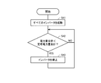
- FIG. 4 is a flowchart for explaining the operation of uninterruptible power supply system 100 according to Embodiment 1 of the present invention.
- the inverter control unit 300 activates the inverters 17, 27, and 37 of all uninterruptible power supply devices 10, 20, and 30 (step S41). Specifically, the inverter control unit 300 outputs a unit number selection command signal for selecting all the inverters 17, 27, 37 to the inverter operation command circuits 304-306 of the inverters 17, 27, 37, and the signal generation circuits 307-- 309 outputs an instruction signal for starting the inverters 17, 27, and 37 to the inverter operation command circuits 304 to 306.
- Inverter operation command circuits 304 to 306 command each inverter 17, 27, 37 to start based on the number selection command signal output from inverter control unit 300 and the instruction signal output from signal generation circuits 307 to 309. A command signal is output. Each inverter 17, 27, 37 is started based on the command signal output from the inverter operation command circuits 304-306.
- the inverter control unit 300 includes at least one of the total electric energy output from the inverters 17, 27, and 37 and the activated inverters 17, 27, and 37 to supply the electric energy necessary for the load.
- the total rated power amount output by the remaining inverters is compared, and it is determined whether or not the total power amount is smaller than the total rated power amount (step S42).
- the inverter control unit 300 determines that the total power amount is smaller than the total rated power amount (step S42: YES)
- step S42 NO
- the inverter control unit 300 determines that the total power amount is equal to or greater than the total rated power amount (step S42: NO)
- the inverter control unit 300 returns the process to step S42 to monitor the change in the total power amount. Further, after stopping at least one inverter among the activated inverters 17, 27, and 37 (step S43), the inverter control unit 300 returns the process to step S42 in order to monitor the change in the total electric energy.
- the inverter control unit 300 may stop the inverters 17, 27, 37 in units of one or may stop in units of two or more. When the inverters 17, 27, and 37 are stopped in units of one unit, the inverter control unit 300 totals the amount of power and the remaining inverters when one of the activated inverters 17, 27, and 37 is stopped. Is compared with the total rated power output. Further, when the inverters 17, 27, and 37 are stopped in units of two, the inverter control unit 300 is left when the total amount of power and two of the inverters 17, 27, and 37 that are activated are stopped. Compare the total rated power output from the inverter.
- the uninterruptible power supply system 100 As described above, according to the uninterruptible power supply system 100 according to Embodiment 1 of the present invention, the amount of power required for the load compared to the total rated power amount output by the activated inverters 17, 27, and 37.
- the inverter control part 300 stops the inverter which does not contribute to supply of the electric energy required for load among the inverters 17, 27, and 37, several uninterruptible power supplies connected in parallel
- the utilization efficiency of the devices 10, 20, and 30 can be increased.
- the uninterruptible power supply system 100 according to Embodiment 1 of the present invention stops the inverters 17, 27, and 37 that do not contribute to the supply of the amount of power necessary for the load, the switching loss P sw in the stopped inverter and The steady loss Pc can be suppressed and the power consumption can be reduced. Furthermore, since the uninterruptible power supply system 100 according to the first embodiment of the present invention stops only the inverters 17, 27, and 37, compared to a case where all the circuits of the uninterruptible power supply devices 10, 20, and 30 are stopped. The start time of the uninterruptible uninterruptible power supply 10, 20, 30 can be shortened. Further, in the uninterruptible power supply system 100 according to Embodiment 1 of the present invention, since all converters 15, 25, and 35 are activated, the uninterruptible power supply units 10, 20, and 30 are overloaded. Driving with a load can be avoided.
- the inverter control unit 300 displays the inverter operation command circuit for the inverters 17 and 27.
- the inverter 37 is stopped by outputting the “ON” number selection command signal to 304 and 305 and the “OFF” number selection command signal to the inverter operation command circuit 306 of the inverter 37, respectively.
- the inverter control unit 300 sets the number of “ON” in the inverter operation command circuit 304 of the inverter 17. By outputting the selection command signal to the inverter operation command circuits 305 and 306 of the inverters 27 and 37, the number selection command signals of “OFF” are respectively output, and the inverters 27 and 37 are stopped.
- the inverter control unit 300 activates the stopped inverter, Power can be stably supplied to the load.
- the uninterruptible power supply system according to the second embodiment of the present invention has an AC input unit 1, an input / output / switching unit 2, a control unit 3, and a DC branching unit 4. , Storage battery 5, output unit 6, AC output units 7 and 8, uninterruptible power supply 10, 20, and 30. Therefore, the uninterruptible power supply system according to Embodiment 2 of the present invention uses the same reference numerals for the same components as uninterruptible power supply system 100 according to Embodiment 1, and does not repeat detailed description.
- FIG. 5 is a flowchart for explaining the operation of the uninterruptible power supply system according to Embodiment 2 of the present invention.
- the inverter control unit 300 activates a predetermined number of inverters among the inverters 17, 27, and 37 of the uninterruptible power supply 10, 20, and 30 (step S51).
- the inverter control unit 300 sets the predetermined number of inverters to be half of the number of inverters included in the uninterruptible power supply. For example, when the number of inverters included in the uninterruptible power supply is four, the inverter control unit 300 sets the predetermined number of inverters to be activated to two. When the number of inverters included in the uninterruptible power supply is an odd number, the inverter control unit 300 sets the number obtained by raising the predetermined number for starting the inverter as the predetermined number.
- the inverter control unit 300 outputs a number selection command signal for selecting two of the inverters 17, 27.
- the signal generation circuits 307 and 308 output instruction signals for starting the inverters 17 and 27 to the inverter operation command circuits 304 and 305, respectively.
- the inverter operation command circuits 304 and 305 are command signals for instructing the inverters 17 and 27 to start up based on the number selection command signal output from the inverter control unit 300 and the instruction signal output from the signal generation circuits 307 and 308. Is output.
- the inverters 17 and 27 are activated based on the command signals output from the inverter operation command circuits 304 and 305.
- the inverter control unit 300 includes a total power amount output from the inverters 17 and 27 to supply a necessary power amount to the load, and a first total rated power amount output from the activated inverters 17 and 27. To determine whether or not the total power amount is equal to or greater than the first rated power amount total (step S52).
- the inverter control unit 300 starts the inverter 37 by outputting an “ON” number selection command signal to the inverter operation command circuit 306 of the inverter 37.
- step S53 the inverter control part 300 returns a process to monitoring the change of total electric energy to step S52.
- step S52 NO
- the total electric energy and at least one inverter among the activated inverters 17 and 27 are included. Is compared with the second rated power total output from the remaining inverters, and it is determined whether the total power is smaller than the second rated power total (step S54).
- the inverter control unit 300 determines that the total power amount is smaller than the second rated power amount total (step S54: YES)
- step S55 NO
- the inverter control unit 300 determines that the total power amount is equal to or greater than the second rated power amount total (step S55: NO)
- the inverter control unit 300 returns the process to step S52 in order to monitor the change in the total power amount.
- Inverter control unit 300 stops at least one of the activated inverters 17 and 27 (step S55), and then returns the process to step S52 in order to monitor the change in the total electric energy.
- the inverter control unit 300 stops one inverter among the activated inverters 17 and 27. If there are three or more inverters, at least one inverter among the activated inverters may be stopped.
- the amount of power required for the load is smaller than the total rated power amount output by the activated inverters 17 and 27 ( In the case of low load), the inverter control unit 300 stops at least one of the activated inverters 17 and 27, so that the utilization efficiency of the plurality of uninterruptible power supplies 10, 20, and 30 connected in parallel is reduced. Can be increased. Further, in the uninterruptible power supply system according to Embodiment 2 of the present invention, the amount of power required for the load is larger (overload) than the total rated power amount output by the activated inverters 17 and 27. Since the stopped inverter 37 is started, overload operation can be avoided, and the life of the uninterruptible power supplies 10, 20, 30 and the storage battery 5 can be extended.
- the uninterruptible power supply system according to the third embodiment of the present invention is similar to the uninterruptible power supply system 100 according to the first embodiment in the AC input unit 1, the input / output / switching unit 2, the control unit 3, and the DC branching unit 4. , Storage battery 5, output unit 6, AC output units 7 and 8, uninterruptible power supply 10, 20, and 30. Therefore, the uninterruptible power supply system according to Embodiment 3 of the present invention uses the same reference numerals for the same components as uninterruptible power supply system 100 according to Embodiment 1, and does not repeat detailed description.
- FIG. 6 is a flowchart for explaining the operation of the uninterruptible power supply system according to Embodiment 3 of the present invention.
- the inverter control unit 300 activates one inverter among the inverters 17, 27, and 37 of the uninterruptible power supply 10, 20, and 30 (step S61).
- the inverter control unit 300 sends a number selection command signal for selecting one of the inverters 17 to the inverter 17.
- the signal generation circuit 307 outputs an instruction signal for starting the inverter 17 to the inverter operation command circuit 304.
- the inverter operation command circuit 304 outputs a command signal for instructing the inverter 17 to start based on the number selection command signal output from the inverter control unit 300 and the instruction signal output from the signal generation circuit 307.
- the inverter 17 is activated based on the command signal output from the inverter operation command circuit 301.
- the inverter control unit 300 compares the total amount of power output from the inverter 17 to supply the necessary amount of power to the load with the first total rated power amount output from the activated inverter 17. It is determined whether the total power amount is equal to or greater than the first rated power amount total (step S62).
- the inverter control unit 300 starts the inverter 27 by outputting an “ON” number selection command signal to the inverter operation command circuit 305 of the inverter 27.
- step S63 the inverter control part 300 returns a process to step S62 in order to monitor the change of the electric energy total.
- step S62 NO
- the remaining power amount is stopped when one of the activated inverters is stopped.
- the second total rated power amount output from the inverter is compared, and it is determined whether the total power amount is smaller than the second total rated power amount (step S64). Note that the process of step S64 is executed only when two or more inverters are activated. Therefore, when one inverter is activated, the process of step S64 is skipped.
- two inverters 17 and 27 are activated will be described as an example.
- step S64 determines that the total amount of power is smaller than the second total rated power amount (step S64: YES)
- step S65 NO
- the inverter control unit 300 determines that the total power amount is equal to or greater than the second rated power amount total (step S65: NO)
- the inverter control unit 300 returns the process to step S62 in order to monitor the change in the total power amount. Further, after stopping one of the activated inverters 17 and 27 (step S65), the inverter control unit 300 returns the process to step S62 in order to monitor the change in the total electric energy.
- the uninterruptible power supply system As described above, according to the uninterruptible power supply system according to Embodiment 3 of the present invention, the amount of power required for the load is smaller than the total rated power amount output by the activated inverters 17 and 27 ( In the case of low load), the inverter control unit 300 stops one of the activated inverters 17 and 27, so that the utilization efficiency of the plurality of uninterruptible power supply devices 10, 20, and 30 connected in parallel is increased. Can do. Further, the uninterruptible power supply system according to Embodiment 3 of the present invention stops when the amount of power required for the load is larger (overload) than the total rated power amount output by the activated inverter 17. Since one of the inverters 27 and 37 is started, overload operation can be avoided, and the life of the uninterruptible power supply devices 10, 20, 30 and the storage battery 5 can be extended.
- the inverters are started or stopped one by one, so that the inverters 17, 27, 37 (uninterruptible power supply units 10, 20, 30) are started wastefully. Therefore, power consumption can be further reduced.
Landscapes
- Engineering & Computer Science (AREA)
- Power Engineering (AREA)
- Business, Economics & Management (AREA)
- Emergency Management (AREA)
- Stand-By Power Supply Arrangements (AREA)
- Inverter Devices (AREA)
Abstract
Description
(実施の形態1)
図1は、本発明の実施の形態1に係る無停電電源システムの構成を示す概略図である。図1に示す無停電電源システム100は、交流入力部1、入出力・切替部2、制御部3、直流分岐部4、蓄電池5、出力部6、交流出力部7,8、無停電電源装置10,20,30を含んでいる。 Hereinafter, embodiments according to the present invention will be described with reference to the drawings.
(Embodiment 1)
FIG. 1 is a schematic diagram showing a configuration of an uninterruptible power supply system according to
本発明の実施の形態2に係る無停電電源システムは、実施の形態1に係る無停電電源システム100と同様に、交流入力部1、入出力・切替部2、制御部3、直流分岐部4、蓄電池5、出力部6、交流出力部7,8、無停電電源装置10,20,30を含んでいる。そのため、本発明の実施の形態2に係る無停電電源システムは、実施の形態1に係る無停電電源システム100と同じ構成要素について同じ符号を用い、詳細な説明を繰返さない。 (Embodiment 2)
Similarly to the uninterruptible
本発明の実施の形態3に係る無停電電源システムは、実施の形態1に係る無停電電源システム100と同様に、交流入力部1、入出力・切替部2、制御部3、直流分岐部4、蓄電池5、出力部6、交流出力部7,8、無停電電源装置10,20,30を含んでいる。そのため、本発明の実施の形態3に係る無停電電源システムは、実施の形態1に係る無停電電源システム100と同じ構成要素について同じ符号を用い、詳細な説明を繰返さない。 (Embodiment 3)
The uninterruptible power supply system according to the third embodiment of the present invention is similar to the uninterruptible
Claims (5)
- 負荷に対して並列に接続され、電源の状況に応じて前記負荷に電力を供給する前記電源を切替える複数の無停電電源装置(10,20,30)と、
前記無停電電源装置(10,20,30)の前記電源を切替える動作を制御する制御部(3)と、
複数の前記無停電電源装置(10,20,30)に共通に接続される蓄電池(5)と
を備え、
前記無停電電源装置(10,20,30)は、
交流電源の交流電力を直流電力に順変換する順変換部(15,25,35)と、
前記順変換部(15,25,35)で変換した直流電力と、前記蓄電池(5)から入力する直流電力とを切替える切替部と、
前記順変換部(15,25,35)で順変換した直流電力、または前記蓄電池(5)から入力する直流電力を交流電力に逆変換し、前記負荷に電力を供給する逆変換部(17,27,37)とを有し、
前記制御部(3)は、複数の前記逆変換部(17,27,37)のうち、前記負荷に必要な電力量の供給に寄与しない前記逆変換部(17,27,37)を停止する無停電電源システム。 A plurality of uninterruptible power supplies (10, 20, 30) that are connected in parallel to the load and switch the power supply that supplies power to the load according to the state of the power supply;
A control unit (3) for controlling the operation of switching the power supply of the uninterruptible power supply (10, 20, 30);
A storage battery (5) connected in common to the plurality of uninterruptible power supplies (10, 20, 30),
The uninterruptible power supply (10, 20, 30)
A forward converter (15, 25, 35) for forward-converting alternating current power of the alternating current power source into direct current power;
A switching unit that switches between DC power converted by the forward conversion unit (15, 25, 35) and DC power input from the storage battery (5);
DC converter forward-converted by the forward converter (15, 25, 35) or DC power input from the storage battery (5) is reverse-converted to AC power, and an inverse converter (17, 27, 37)
The said control part (3) stops the said reverse conversion part (17,27,37) which does not contribute to supply of the electric energy required for the said load among several said reverse conversion parts (17,27,37). Uninterruptible power system. - 前記制御部(3)は、
すべての前記逆変換部(17,27,37)を起動した後、前記負荷に必要な電力量を供給するために複数の前記逆変換部(17,27,37)が出力する電力量合計と、起動している複数の前記逆変換部(17,27,37)のうち少なくとも前記逆変換部(17,27,37)の1台を停止した場合に残りの前記逆変換部(17,27,37)が出力する定格電力量合計とを比較し、
前記電力量合計が、前記定格電力量合計より小さくなる場合、起動している複数の前記逆変換部(17,27,37)のうち少なくとも前記逆変換部(17,27,37)の1台を停止する請求項1に記載の無停電電源システム。 The control unit (3)
After starting all the inverse conversion units (17, 27, 37), a total amount of electric power output by the plurality of inverse conversion units (17, 27, 37) to supply the necessary electric energy to the load; When at least one of the reverse conversion units (17, 27, 37) is stopped among the plurality of active reverse conversion units (17, 27, 37), the remaining reverse conversion units (17, 27) are stopped. , 37) and the total rated power output from
When the total power amount is smaller than the total rated power amount, at least one of the reverse conversion units (17, 27, 37) among the plurality of reverse conversion units (17, 27, 37) that are activated. The uninterruptible power supply system according to claim 1 which stops operation. - 前記制御部(3)は、
2台以上の所定台数の前記逆変換部(17,27,37)を起動した後、前記負荷に必要な電力量を供給するために複数の前記逆変換部(17,27,37)が出力する電力量合計と、起動している複数の前記逆変換部(17,27,37)が出力する第1定格電力量合計とを比較し、
前記電力量合計が、前記第1定格電力量合計以上の場合、前記第1電力量合計が、前記定格電力量合計より小さくなるまで停止している前記逆変換部(17,27,37)を起動し、
前記電力量合計が、前記第1定格電力量合計より小さい場合、前記電力量合計と、起動している複数の前記逆変換部(17,27,37)のうち少なくとも前記逆変換部(17,27,37)の1台を停止した場合に残りの前記逆変換部(17,27,37)が出力する第2定格電力量合計とを比較し、
前記電力量合計が、前記第2定格電力量合計より小さくなる場合、起動している複数の前記逆変換部(17,27,37)のうち少なくとも前記逆変換部(17,27,37)の1台を停止する請求項1に記載の無停電電源システム。 The control unit (3)
After activating two or more predetermined number of the reverse conversion units (17, 27, 37), a plurality of the reverse conversion units (17, 27, 37) output in order to supply electric power necessary for the load. The total amount of power to be compared with the first total rated power amount output by the plurality of activated reverse conversion units (17, 27, 37),
When the total power amount is equal to or greater than the first rated power amount total, the inverse conversion unit (17, 27, 37) is stopped until the first total power amount becomes smaller than the total rated power amount. Start
When the total power amount is smaller than the first rated power amount total, at least the reverse conversion unit (17, 27, 37) among the total power amount and the plurality of reverse conversion units (17, 27, 37) that are activated. 27, 37) is compared with the second rated power total output by the remaining inverse converters (17, 27, 37) when one of the units is stopped,
When the total electric energy is smaller than the second rated electric energy total, at least the inverse conversion unit (17, 27, 37) among the plurality of activated inverse conversion units (17, 27, 37). The uninterruptible power supply system according to claim 1, wherein one unit is stopped. - 前記制御部(3)は、前記逆変換部(17,27,37)を起動する前記所定台数を、複数の前記無停電電源装置(10,20,30)が有する前記逆変換部(17,27,37)の台数の半分とする請求項3に記載の無停電電源システム。 The control unit (3) includes a plurality of the uninterruptible power supply units (10, 20, 30) having the predetermined number for starting the reverse conversion unit (17, 27, 37). 27. The uninterruptible power supply system according to claim 3, wherein the number of the uninterruptible power supplies is half of the number of units.
- 前記制御部(3)は、
前記逆変換部(17,27,37)を1台起動した後、前記負荷に必要な電力量を供給するために複数の前記逆変換部(17,27,37)が出力する電力量合計と、起動している複数の前記逆変換部(17,27,37)が出力する第1定格電力量合計とを比較し、
前記電力量合計が、前記第1定格電力量合計以上の場合、前記第1電力量合計が、前記定格電力量合計より小さくなるまで停止している前記逆変換部(17,27,37)を1台ずつ起動し、
前記電力量合計が、前記第1定格電力量合計より小さい場合、前記電力量合計と、起動している複数の前記逆変換部(17,27,37)のうちの前記逆変換部(17,27,37)の1台を停止した場合に残りの前記逆変換部(17,27,37)が出力する第2定格電力量合計とを比較し、
前記電力量合計が、前記第2定格電力量合計より小さくなる場合、起動している複数の前記逆変換部(17,27,37)のうちの前記逆変換部(17,27,37)の1台を停止する請求項1に記載の無停電電源システム。 The control unit (3)
After activating one of the inverse converters (17, 27, 37), a total amount of power output by the plurality of inverse converters (17, 27, 37) to supply the necessary amount of power to the load; , Comparing the first rated power total output from the plurality of inverse conversion units (17, 27, 37) that are activated,
When the total power amount is equal to or greater than the first rated power amount total, the inverse conversion unit (17, 27, 37) is stopped until the first total power amount becomes smaller than the total rated power amount. Start one by one,
When the total power amount is smaller than the first rated power amount total, the total power amount and the inverse conversion unit (17, 27, 37) among the plurality of activated reverse conversion units (17, 27, 37). 27, 37) is compared with the second rated power total output by the remaining inverse converters (17, 27, 37) when one of the units is stopped,
When the total electric energy is smaller than the total second rated electric energy, the inverse conversion unit (17, 27, 37) of the plurality of activated inverse conversion units (17, 27, 37) The uninterruptible power supply system according to claim 1, wherein one unit is stopped.
Priority Applications (6)
| Application Number | Priority Date | Filing Date | Title |
|---|---|---|---|
| JP2013519311A JP5732134B2 (en) | 2011-06-09 | 2011-06-09 | Uninterruptible power supply system |
| BR112013031623A BR112013031623B1 (en) | 2011-06-09 | 2011-06-09 | uninterruptible power supply system |
| CN201180071491.3A CN103620912A (en) | 2011-06-09 | 2011-06-09 | Uninterruptible power supply system |
| PCT/JP2011/063252 WO2012169046A1 (en) | 2011-06-09 | 2011-06-09 | Uninterruptible power supply system |
| US14/118,449 US10284006B2 (en) | 2011-06-09 | 2011-06-09 | Uninterruptible power supply system |
| CN201810107102.1A CN108134450A (en) | 2011-06-09 | 2011-06-09 | Uninterruptible power system |
Applications Claiming Priority (1)
| Application Number | Priority Date | Filing Date | Title |
|---|---|---|---|
| PCT/JP2011/063252 WO2012169046A1 (en) | 2011-06-09 | 2011-06-09 | Uninterruptible power supply system |
Publications (2)
| Publication Number | Publication Date |
|---|---|
| WO2012169046A1 true WO2012169046A1 (en) | 2012-12-13 |
| WO2012169046A9 WO2012169046A9 (en) | 2013-12-27 |
Family
ID=47295648
Family Applications (1)
| Application Number | Title | Priority Date | Filing Date |
|---|---|---|---|
| PCT/JP2011/063252 WO2012169046A1 (en) | 2011-06-09 | 2011-06-09 | Uninterruptible power supply system |
Country Status (5)
| Country | Link |
|---|---|
| US (1) | US10284006B2 (en) |
| JP (1) | JP5732134B2 (en) |
| CN (2) | CN103620912A (en) |
| BR (1) | BR112013031623B1 (en) |
| WO (1) | WO2012169046A1 (en) |
Cited By (7)
| Publication number | Priority date | Publication date | Assignee | Title |
|---|---|---|---|---|
| JP2015089211A (en) * | 2013-10-30 | 2015-05-07 | 東芝三菱電機産業システム株式会社 | Uninterruptible power supply system |
| JP2015198547A (en) * | 2014-04-03 | 2015-11-09 | 株式会社新愛知電機製作所 | Hybrid-type power source switching device |
| JP2016073017A (en) * | 2014-09-26 | 2016-05-09 | 京セラ株式会社 | Power supply apparatus, power supply method and power supply system |
| US20170163088A1 (en) * | 2014-06-26 | 2017-06-08 | Toshiba Mitsubishi-Electric Industrial Systems Corporation | Uninterruptible power source |
| US10236714B2 (en) | 2015-04-30 | 2019-03-19 | Abb Schweiz Ag | UPS operation with high converter efficiency |
| JP2020195174A (en) * | 2019-05-24 | 2020-12-03 | 東芝三菱電機産業システム株式会社 | Uninterruptible power supply system |
| JP2021010234A (en) * | 2019-07-01 | 2021-01-28 | サンケン電気株式会社 | Uninterruptible power supply device system |
Families Citing this family (22)
| Publication number | Priority date | Publication date | Assignee | Title |
|---|---|---|---|---|
| CN103608996A (en) * | 2011-06-09 | 2014-02-26 | 东芝三菱电机产业系统株式会社 | Uninterruptible power supply system |
| US10193358B2 (en) * | 2012-04-23 | 2019-01-29 | Hewlett Packard Enterprise Development Lp | Deep-charging power resources of power resource group having identifier corresponding to range within which modulo falls based on charging time |
| JPWO2014167830A1 (en) * | 2013-04-09 | 2017-02-16 | 日本電気株式会社 | Power control system |
| WO2015108614A1 (en) * | 2014-01-15 | 2015-07-23 | Abb Technology Ag | Modular, multi-channel, interleaved power converters |
| CN104505878A (en) * | 2014-12-12 | 2015-04-08 | 国家电网公司 | Portable voltage-stabilizing mobile power supply device |
| CN105991080B (en) * | 2015-02-26 | 2021-09-10 | 伊顿智能动力有限公司 | Connecting device for motor and power supply network |
| CA2984331C (en) * | 2015-06-02 | 2019-10-29 | Toshiba Mitsubishi-Electric Industrial Systems Corporation | Uninterruptible power supply device |
| CN104852606A (en) * | 2015-06-03 | 2015-08-19 | 吉林瀚丰电气有限公司 | Low-voltage rectifier cabinet with real-time monitoring and intelligent switching functions |
| CN105305599B (en) * | 2015-10-16 | 2017-12-26 | 中国船舶工业系统工程研究院 | A kind of warship ups power equipment |
| GB2544510A (en) * | 2015-11-19 | 2017-05-24 | Ge Oil & Gas Uk Ltd | Conditioning electrical power |
| JP6660553B2 (en) * | 2015-11-30 | 2020-03-11 | パナソニックIpマネジメント株式会社 | POWER SUPPLY, POWER SUPPLY CONTROL METHOD, AND POWER SUPPLY CONTROL PROGRAM |
| US20170373522A1 (en) * | 2016-06-23 | 2017-12-28 | Apple Inc. | Charging System |
| JP6090523B1 (en) | 2016-08-10 | 2017-03-08 | 富士電機株式会社 | Uninterruptible power system |
| CN106787225B (en) * | 2016-10-21 | 2020-06-02 | 国家电网公司 | Energy storage device for electric automobile quick charging |
| US20190312540A1 (en) * | 2018-04-07 | 2019-10-10 | Shakti Pumps (India) Ltd. | Method and apparatus for soft starting and stopping a motor |
| CN113726137B (en) | 2020-05-26 | 2023-11-03 | 台达电子企业管理(上海)有限公司 | conversion device |
| CN113726136B (en) * | 2020-05-26 | 2023-11-03 | 台达电子企业管理(上海)有限公司 | conversion device |
| US11355956B1 (en) * | 2020-12-08 | 2022-06-07 | Schneider Electric It Corporation | High-efficiency modular uninterruptible power supply |
| DE102021210940A1 (en) * | 2021-09-30 | 2023-03-30 | Siemens Aktiengesellschaft | Arrangement comprising at least two uninterruptible power supplies and methods for their operation |
| US11884179B2 (en) | 2021-10-04 | 2024-01-30 | Ford Global Technologies, Llc | Bidirectional energy transfer system and method that utilize a supply device |
| US20240097484A1 (en) * | 2022-09-21 | 2024-03-21 | Schneider Electric It Corporation | Systems and methods for operating with secondary power sources |
| US20240154419A1 (en) * | 2022-11-02 | 2024-05-09 | Switched Source PB, LLC | High speed protection for phase balancer with zig-zag transformer |
Citations (3)
| Publication number | Priority date | Publication date | Assignee | Title |
|---|---|---|---|---|
| JPS50150853A (en) * | 1974-05-23 | 1975-12-03 | ||
| WO2011033820A1 (en) * | 2009-09-16 | 2011-03-24 | 東芝三菱電機産業システム株式会社 | Power conversion system and uninterruptible power source system |
| JP2011072068A (en) * | 2009-09-24 | 2011-04-07 | Toshiba Mitsubishi-Electric Industrial System Corp | Uninterruptible power supply system |
Family Cites Families (31)
| Publication number | Priority date | Publication date | Assignee | Title |
|---|---|---|---|---|
| AU2296677A (en) * | 1976-03-10 | 1978-09-14 | Westinghouse Electric Corp | Load balancing system for ups rectifiers |
| JP2760053B2 (en) * | 1988-08-12 | 1998-05-28 | 富士電機株式会社 | Fuel cell generator and driving method thereof |
| US5629844A (en) * | 1995-04-05 | 1997-05-13 | International Power Group, Inc. | High voltage power supply having multiple high voltage generators |
| US6281596B1 (en) * | 1999-11-19 | 2001-08-28 | Capstone Turbine Corporation | Automatic turbogenerator restarting method and system |
| JP2002058176A (en) * | 2000-08-10 | 2002-02-22 | Mitsubishi Electric Corp | Power conversion apparatus |
| US6700804B1 (en) * | 2000-11-02 | 2004-03-02 | American Superconductor Corporation | Integrated multi-level inverter assembly |
| JP3851584B2 (en) | 2002-03-28 | 2006-11-29 | 東芝三菱電機産業システム株式会社 | Parallel operation method of uninterruptible power supply |
| JP4071675B2 (en) * | 2003-05-27 | 2008-04-02 | 東芝三菱電機産業システム株式会社 | Uninterruptible power supply parallel operation system |
| US6940735B2 (en) * | 2003-11-14 | 2005-09-06 | Ballard Power Systems Corporation | Power converter system |
| US7105949B2 (en) * | 2004-01-22 | 2006-09-12 | Delta Electronics, Inc. | Emergent power supply system and method of achieving input current balance in such system |
| JP2005287137A (en) * | 2004-03-29 | 2005-10-13 | Honda Motor Co Ltd | Discharger of smoothing capacitor |
| JP2005287136A (en) * | 2004-03-29 | 2005-10-13 | Honda Motor Co Ltd | Precharger of smoothing capacitor |
| US7265458B2 (en) * | 2005-04-08 | 2007-09-04 | Eaton Power Quality Corporation | Apparatus and methods for coordinated static switch operations for load transfers in uninterruptible power supply systems |
| TW200721635A (en) * | 2005-11-18 | 2007-06-01 | Delta Electronics Inc | Parallel-type uninterruptible power supply system |
| US7638899B2 (en) * | 2006-03-10 | 2009-12-29 | Eaton Corporation | Nested redundant uninterruptible power supply apparatus and methods |
| US20070273216A1 (en) * | 2006-05-24 | 2007-11-29 | Farbarik John M | Systems and Methods for Reducing Power Losses in a Medical Device |
| JP4760723B2 (en) * | 2006-11-20 | 2011-08-31 | トヨタ自動車株式会社 | Power supply circuit control device |
| US7679217B2 (en) * | 2007-12-28 | 2010-03-16 | International Business Machines Corporation | Apparatus, system, and method for a high efficiency redundant power system |
| US7486099B1 (en) * | 2008-02-28 | 2009-02-03 | Caterpillar Inc. | System and method for testing power transistors |
| CN102217162B (en) | 2008-11-19 | 2014-05-21 | 东芝三菱电机产业系统株式会社 | Secondary battery system |
| US7906871B2 (en) * | 2008-12-30 | 2011-03-15 | International Business Machines Corporation | Apparatus, system, and method for reducing power consumption on devices with multiple power supplies |
| CA2761022C (en) * | 2009-04-17 | 2015-08-18 | Toshiba Mitsubishi-Electric Industrial Systems Corporation | Uninterruptible power supply system |
| CN101902056B (en) * | 2009-06-01 | 2015-06-17 | Ge医疗系统环球技术有限公司 | Uninterruptable power supply and method for saving electricity of same |
| JP5591247B2 (en) * | 2009-09-16 | 2014-09-17 | 東芝三菱電機産業システム株式会社 | Power conversion system and uninterruptible power supply system |
| WO2011139833A2 (en) * | 2010-04-29 | 2011-11-10 | Enphase Energy, Inc. | Method and apparatus for distributed power generation |
| KR101113508B1 (en) * | 2010-05-06 | 2012-02-29 | 성균관대학교산학협력단 | Apparatus and method for charging and discharging photovoltaic pcs integrated battery |
| CN102035251A (en) * | 2010-12-24 | 2011-04-27 | 深圳市华通电气设备有限公司 | Weak current comprehensive uninterrupted power supply (UPS) system for railway |
| US8587208B2 (en) * | 2011-04-29 | 2013-11-19 | Osram Sylvania Inc. | Multiple strike ballast for electrodeless lamp |
| EP2755293A1 (en) * | 2013-01-11 | 2014-07-16 | Siemens Aktiengesellschaft | Hot standby power supply for a variable frequency drive |
| US9042131B2 (en) * | 2013-02-15 | 2015-05-26 | Ideal Power Inc. | Power-packet-switching converter with sequenced connection to link inductor |
| BR112015029148A2 (en) * | 2013-05-20 | 2017-07-25 | Ge Energy Power Conversion Technology Ltd | device, method for preloading an input filter and computer readable tangible medium |
-
2011
- 2011-06-09 WO PCT/JP2011/063252 patent/WO2012169046A1/en active Application Filing
- 2011-06-09 US US14/118,449 patent/US10284006B2/en active Active
- 2011-06-09 BR BR112013031623A patent/BR112013031623B1/en active IP Right Grant
- 2011-06-09 CN CN201180071491.3A patent/CN103620912A/en active Pending
- 2011-06-09 JP JP2013519311A patent/JP5732134B2/en active Active
- 2011-06-09 CN CN201810107102.1A patent/CN108134450A/en active Pending
Patent Citations (3)
| Publication number | Priority date | Publication date | Assignee | Title |
|---|---|---|---|---|
| JPS50150853A (en) * | 1974-05-23 | 1975-12-03 | ||
| WO2011033820A1 (en) * | 2009-09-16 | 2011-03-24 | 東芝三菱電機産業システム株式会社 | Power conversion system and uninterruptible power source system |
| JP2011072068A (en) * | 2009-09-24 | 2011-04-07 | Toshiba Mitsubishi-Electric Industrial System Corp | Uninterruptible power supply system |
Cited By (10)
| Publication number | Priority date | Publication date | Assignee | Title |
|---|---|---|---|---|
| JP2015089211A (en) * | 2013-10-30 | 2015-05-07 | 東芝三菱電機産業システム株式会社 | Uninterruptible power supply system |
| JP2015198547A (en) * | 2014-04-03 | 2015-11-09 | 株式会社新愛知電機製作所 | Hybrid-type power source switching device |
| US20170163088A1 (en) * | 2014-06-26 | 2017-06-08 | Toshiba Mitsubishi-Electric Industrial Systems Corporation | Uninterruptible power source |
| US10014718B2 (en) * | 2014-06-26 | 2018-07-03 | Toshiba Mitsubishi-Electric Industrial Systems Corporation | Uninterruptible power source |
| JP2016073017A (en) * | 2014-09-26 | 2016-05-09 | 京セラ株式会社 | Power supply apparatus, power supply method and power supply system |
| US10236714B2 (en) | 2015-04-30 | 2019-03-19 | Abb Schweiz Ag | UPS operation with high converter efficiency |
| JP2020195174A (en) * | 2019-05-24 | 2020-12-03 | 東芝三菱電機産業システム株式会社 | Uninterruptible power supply system |
| JP7242427B2 (en) | 2019-05-24 | 2023-03-20 | 東芝三菱電機産業システム株式会社 | uninterruptible power system |
| JP2021010234A (en) * | 2019-07-01 | 2021-01-28 | サンケン電気株式会社 | Uninterruptible power supply device system |
| JP7347752B2 (en) | 2019-07-01 | 2023-09-20 | 株式会社Gsユアサ | uninterruptible power supply system |
Also Published As
| Publication number | Publication date |
|---|---|
| US10284006B2 (en) | 2019-05-07 |
| WO2012169046A9 (en) | 2013-12-27 |
| BR112013031623A2 (en) | 2016-12-06 |
| JP5732134B2 (en) | 2015-06-10 |
| JPWO2012169046A1 (en) | 2015-02-23 |
| BR112013031623B1 (en) | 2020-04-28 |
| US20140210271A1 (en) | 2014-07-31 |
| CN103620912A (en) | 2014-03-05 |
| CN108134450A (en) | 2018-06-08 |
Similar Documents
| Publication | Publication Date | Title |
|---|---|---|
| JP5732134B2 (en) | Uninterruptible power supply system | |
| JP5631490B2 (en) | Uninterruptible power supply system | |
| EP3116096B1 (en) | Ups circuit | |
| WO2015198447A1 (en) | Uninterruptible power supply | |
| WO2021169430A1 (en) | Power supply apparatus, power supply system and data center | |
| CN104662484A (en) | Power conditioner, and method for controlling same | |
| JP2023525117A (en) | A method of operating an electrolyser, a connection circuit for carrying out this method, a rectifier and an electrolysis system | |
| WO2012167691A1 (en) | Inverter device and solar grid-connected photovoltaic system using same | |
| US9203323B2 (en) | Very high efficiency uninterruptible power supply | |
| JP2013074792A (en) | Method for compensating instantaneous power failure in high voltage inverter and high voltage inverter system using the same | |
| JP2010518806A (en) | Inverter | |
| JP6718019B2 (en) | Power supply | |
| KR20220096958A (en) | Switching operation method and an inverter device for grid connection considering transformer magnetization | |
| JP6591057B2 (en) | Power conversion system for grid connection | |
| JP4578113B2 (en) | Electric motor power failure control device | |
| JP6444204B2 (en) | Power converter | |
| JP2005218199A5 (en) | ||
| JP2017175862A (en) | Electric power conversion system | |
| JP2015233380A (en) | Charge/discharge device | |
| JP2020162346A (en) | System interconnection device | |
| JP6227984B2 (en) | Power conversion device and power conversion method | |
| JP2011139556A (en) | Power supply system | |
| JPH01241609A (en) | Photovoltaic power generating system | |
| KR20160064566A (en) | Control apparatus of power generation | |
| JP2012253916A (en) | Power conversion device |
Legal Events
| Date | Code | Title | Description |
|---|---|---|---|
| 121 | Ep: the epo has been informed by wipo that ep was designated in this application |
Ref document number: 11867287 Country of ref document: EP Kind code of ref document: A1 |
|
| ENP | Entry into the national phase |
Ref document number: 2013519311 Country of ref document: JP Kind code of ref document: A |
|
| WWE | Wipo information: entry into national phase |
Ref document number: 14118449 Country of ref document: US |
|
| NENP | Non-entry into the national phase |
Ref country code: DE |
|
| REG | Reference to national code |
Ref country code: BR Ref legal event code: B01A Ref document number: 112013031623 Country of ref document: BR |
|
| 122 | Ep: pct application non-entry in european phase |
Ref document number: 11867287 Country of ref document: EP Kind code of ref document: A1 |
|
| ENP | Entry into the national phase |
Ref document number: 112013031623 Country of ref document: BR Kind code of ref document: A2 Effective date: 20131209 |