WO2012168985A1 - 画像処理方法及びその装置 - Google Patents
画像処理方法及びその装置 Download PDFInfo
- Publication number
- WO2012168985A1 WO2012168985A1 PCT/JP2011/003319 JP2011003319W WO2012168985A1 WO 2012168985 A1 WO2012168985 A1 WO 2012168985A1 JP 2011003319 W JP2011003319 W JP 2011003319W WO 2012168985 A1 WO2012168985 A1 WO 2012168985A1
- Authority
- WO
- WIPO (PCT)
- Prior art keywords
- image
- pixel
- noise
- noise suppression
- image processing
- Prior art date
- Legal status (The legal status is an assumption and is not a legal conclusion. Google has not performed a legal analysis and makes no representation as to the accuracy of the status listed.)
- Ceased
Links
Images




Classifications
-
- A—HUMAN NECESSITIES
- A61—MEDICAL OR VETERINARY SCIENCE; HYGIENE
- A61B—DIAGNOSIS; SURGERY; IDENTIFICATION
- A61B6/00—Apparatus or devices for radiation diagnosis; Apparatus or devices for radiation diagnosis combined with radiation therapy equipment
- A61B6/52—Devices using data or image processing specially adapted for radiation diagnosis
- A61B6/5258—Devices using data or image processing specially adapted for radiation diagnosis involving detection or reduction of artifacts or noise
-
- G—PHYSICS
- G06—COMPUTING OR CALCULATING; COUNTING
- G06T—IMAGE DATA PROCESSING OR GENERATION, IN GENERAL
- G06T5/00—Image enhancement or restoration
- G06T5/20—Image enhancement or restoration using local operators
-
- G—PHYSICS
- G06—COMPUTING OR CALCULATING; COUNTING
- G06T—IMAGE DATA PROCESSING OR GENERATION, IN GENERAL
- G06T5/00—Image enhancement or restoration
- G06T5/70—Denoising; Smoothing
-
- G—PHYSICS
- G06—COMPUTING OR CALCULATING; COUNTING
- G06T—IMAGE DATA PROCESSING OR GENERATION, IN GENERAL
- G06T2207/00—Indexing scheme for image analysis or image enhancement
- G06T2207/10—Image acquisition modality
- G06T2207/10116—X-ray image
-
- G—PHYSICS
- G06—COMPUTING OR CALCULATING; COUNTING
- G06T—IMAGE DATA PROCESSING OR GENERATION, IN GENERAL
- G06T2207/00—Indexing scheme for image analysis or image enhancement
- G06T2207/20—Special algorithmic details
- G06T2207/20004—Adaptive image processing
- G06T2207/20012—Locally adaptive
Definitions
- the present invention relates to an image processing method and apparatus for suppressing noise components in an X-ray image, and more particularly to recognition of a structure in an X-ray image.
- a plurality of band images are created from an input image (for example, a fluoroscopic image). Then, in each of the plurality of band images, pixel energy is calculated for each target pixel while setting each pixel as the target pixel. This pixel energy is an index value used to represent the size of the structure present in the input image (inverse of flatness).
- processing for suppressing noise is performed for each band image using the index value to suppress noise in the input image (see, for example, Patent Document 1). For example, noise suppression processing is performed in the structure and its vicinity so that noise suppression is weak because noise is low, and noise suppression is increased in other regions.
- the pixel energy described above is Ve
- the gradient is n
- the gradient n is a different direction
- each direction is represented by 0, 1, 2, and 3
- the pixel value of the band image is SB
- each band image is m
- the pixel energy Ve is specifically calculated by the following equation.
- q ′ n, m GradientFilter n (SB m )
- q n, m GaussFilter n (
- Ve m [i] (q 0, m [i] + q 1, m [i] + q 2, m [i] + q 3, m [i]) / 4
- a gradient filter in four directions of 0 °, 45 °, 90 °, and 135 ° is applied to the band image, and each component of the gradient in the four directions at the target pixel is calculated as q ′ n, m .
- a Gaussian filter is applied to the absolute value of each component in the four directions for each pixel of interest to calculate the magnitude of each direction component as q n, m .
- the average value of the size of each direction component in each pixel of interest is obtained, and this is obtained as the pixel energy Ve for each pixel.
- X-ray fluoroscopic images under low dose conditions and X-ray radiographic images with low dose levels have higher signal strength than X-ray fluoroscopic images under high dose conditions and X-ray radiographic images with high dose levels. Is weak and the noise intensity is high. Therefore, it is difficult to distinguish between a signal indicating a structure in an X-ray image and a signal indicating noise. For this reason, in the above-described conventional example, it is possible to reduce erroneous detection of a noise component as a signal by taking an absolute value average with respect to gradients in four directions of pixels.
- the wire mentioned above is a guide wire inserted in advance of the catheter in, for example, an operation method using the catheter. Therefore, the wire may appear to be broken or connected in the X-ray fluoroscopic image, which may hinder the catheter operation.
- FIG. 7A and 7B are X-ray images after noise suppression processing according to a conventional example.
- FIG. 7A is an overall view and FIG. 7B is a partially enlarged view.
- FIG. 7 (a) is an X-ray image obtained by laminating several acrylic plates, shifting the positions so as to form a staircase, and imaging the wire on the uppermost surface. As shown in the enlarged portion of FIG. 7B, a part of the wire that should be continuous appears broken.
- the present invention has been made in view of such circumstances, and an object of the present invention is to provide an image processing method and apparatus capable of enhancing structure recognition by devising an algorithm.
- the present invention has the following configuration. That is, the image processing method according to the present invention is an image processing method for suppressing noise in an X-ray image, a band image generation process for generating band images of different frequency bands from input images, and each pixel of interest for each band image. A pixel energy calculation process for calculating the maximum value of the magnitudes of gradient components in different directions in each pixel as the pixel energy of the target pixel, and noise suppression for suppressing noise on the input image based on the pixel energy And a process.
- the band image generation process band images of different frequency bands are obtained from the input image, and in the pixel energy calculation process, the magnitudes of gradient components in different directions in each pixel of interest are different. Is calculated as the pixel energy of the target pixel.
- the absolute value average of the magnitudes of the gradient components in a plurality of directions is not calculated, but the maximum value is calculated as the pixel energy. Therefore, the pixel energy is calculated larger than in the conventional example. That is, a signal corresponding to a structural portion in the input image can be strongly recognized. Therefore, in the noise suppression process, noise suppression is performed on the input image based on the pixel energy. Therefore, it is possible to increase the noise suppression other than the part recognized as the structure, or weaken the noise suppression of the part recognized as the structure. Control of noise processing in an image can be easily performed. As a result, the quality of the input image can be improved.
- the pixel energy calculation process sets four directions of the gradient component as four directions. By limiting the plurality of gradient component directions to four directions, the calculation load can be reduced.
- the noise suppression process obtains a dose based on the input image and a signal value-dose conversion corresponding to a preset reference dose value, and based on the dose and the pixel energy. It is preferable to use the calculated noise suppression degree. Since the pixel energy is calculated to be large in the structure part, it is easy to distinguish between the structure part and the other parts, and the noise suppression degree can be calculated appropriately. Therefore, noise processing can be appropriately performed by using the noise suppression degree.
- the present invention relates to an image processing apparatus for suppressing noise of an X-ray image, an image processing apparatus for suppressing noise of an X-ray image, and band image generation means for generating band images of different frequency bands from an input image; Pixel energy calculating means for calculating the maximum value of the magnitude values of gradient components in different directions in each pixel of interest for each image as the pixel energy of the pixel of interest, and an input image based on the pixel energy Noise suppression means for suppressing noise with respect to.
- the band image generation means obtains band images of different frequency bands from the input image, and the pixel energy calculation means determines the magnitudes of gradient components in different directions in each pixel of interest. Is calculated as the pixel energy of the target pixel.
- the absolute value average of the magnitudes of the gradient components in a plurality of directions is not calculated, but the maximum value is calculated as the pixel energy. Therefore, the pixel energy is calculated larger than in the conventional example. That is, a signal corresponding to a structural portion in the input image is strongly recognized.
- the noise suppression means performs noise suppression on the input image based on the pixel energy, the noise suppression other than the portion recognized as the structure is strengthened, or the noise suppression of the portion recognized as the structure is weakened. Control of noise processing in an image can be easily performed. As a result, the quality of the input image can be improved.
- the pixel energy calculation means sets a plurality of directions of the gradient component as four directions. By limiting the plurality of gradient component directions to four directions, the calculation load on the pixel energy calculation means can be reduced.
- the noise suppression means obtains a dose based on the input image and a signal value-dose conversion corresponding to a preset reference dose value, and based on the dose and the pixel energy. It is preferable to use the calculated noise suppression degree. Since the pixel energy is calculated to be large in the structure part, it is easy to distinguish between the structure part and the other parts, and the noise suppression degree can be calculated appropriately. Therefore, noise processing by the noise suppression unit can be appropriately performed by using the noise suppression degree.
- the image processing method of the present invention in the band image generation process, band images of different frequency bands are obtained, and in the pixel energy calculation process, the absolute values of the magnitudes of gradient components in different directions in each pixel of interest Among these, the maximum is calculated as the pixel energy of the target pixel.
- the absolute value average of the magnitudes of the gradient components in a plurality of directions is not calculated, but the maximum value is calculated as the pixel energy. Therefore, the pixel energy is calculated larger than in the conventional example. That is, a signal corresponding to a structural portion in the input image can be strongly recognized. Therefore, in the noise suppression process, noise suppression is performed on the input image based on the pixel energy. Therefore, it is possible to increase the noise suppression other than the part recognized as the structure, or weaken the noise suppression of the part recognized as the structure. Control of noise processing in an image can be easily performed. As a result, the quality of the input image can be improved.
- FIG. 1 is a schematic diagram for explaining the flow of the image processing method body according to the embodiment
- FIG. 2 is a schematic diagram illustrating an example of a gradient filter.
- a solid line arrow in FIG. 1 indicates a flow of an image
- a dotted line arrow indicates a flow of a feature amount.
- the image processing method handles an X-ray image or an X-ray fluoroscopic image as an input image to be processed.
- the input image is generated as a band image (also referred to as a band limited image) having a plurality of different frequency bands (step S1).
- a band image also referred to as a band limited image
- a generation method by Laplacian pyramid decomposition may be mentioned.
- a generation method by multi-resolution conversion such as wavelet conversion can be adopted for generation of the band image.
- a gradient filter is applied to each band image, and each pixel of each band image is used as a target pixel in order, and gradient components in different directions are obtained for each target pixel (step S2).
- This gradient component is the difference between the pixel value of the pixel of interest and the pixel value of the pixel located in a certain direction from the pixel of interest, and represents the component consisting of the difference in pixel value and the direction.
- the gradient component increases in the direction where the pixel value difference is large in the band image, and the gradient component decreases in the direction where the pixel value difference is small.
- a gradient filter Gradient Filter
- FIG. 2 illustrates an example of a gradient filter of 0 °, 45 °, 90 °, and 135 °, and illustrates a case of a 31 ⁇ 31 pixel spatial filter.
- m is, for example, 1 to 6
- SB the pixel value of each band image
- the above GradientFilter is a kind of primary differential filter. This filter emphasizes more as the difference in pixel values is larger, and the value obtained by this filter represents the strength of the edge.
- the pixel energy Ve is calculated for each pixel i by applying the magnitude q n, m of each direction component to the following equation (step S3).
- Ve m [i] Max (q 0, m [i], q 1, m [i], q 2, m [i], q 3, m [i])
- Max represents selecting the largest one of the magnitudes q n, m [i] of each direction component in parentheses.
- the pixel energy Ve is calculated as the maximum value among the absolute values of the gradient components in four different directions at each pixel position (target pixel) of each band image.
- This pixel energy Ve represents the size of the structure in the image (inverse of flatness), and the larger the value, the higher the probability that the pixel is a structure in the image.
- a gradient vector indicating the direction of the edge is calculated using the magnitudes q n, m of each direction component in each pixel of interest (step S4).
- the gradient vector is calculated because the pixel energy Ve is calculated by taking an absolute value, so that the magnitude can be determined but the direction cannot be determined.
- the gradient vector here indicates a direction and its magnitude (q n, m [i]), and when the above-described four-direction gradient filter is used, 0 °, 45 °, The size in four directions of 90 ° and 135 ° is shown.
- a dose is obtained from the pixel energy Ve, a predetermined reference dose value (step PP1), an input image, and a signal value-dose conversion (step PP2) corresponding to the reference dose value. Based on this, a noise suppression degree is calculated (step S5).
- the reference dose value represents an arbitrary dose value set in advance within the range of doses that can be irradiated with X-rays. For example, the reference dose value is set to a different value depending on a procedure such as X-ray imaging or X-ray fluoroscopy, or an X-ray irradiation site such as a chest or abdomen. When the dose value at the time of obtaining an image is smaller than the reference dose value, the image becomes dark and noise increases.
- the signal value-dose conversion is a table for each reference dose value showing the correspondence between the pixel value corresponding to the signal value and the dose that generates the signal value.
- the noise suppression degree represents the degree of noise removal.
- the edge reliability representing the probability of the edge is calculated for each pixel (step S6). For example, when the gradient vector q n, m [i] is large and the pixel energy Ve is large, the edge reliability indicates that the probability that the pixel represents a structure is high. Further, based on the direction of the gradient vector q n, m [i] whose magnitude is large, a smoothing direction representing the direction in which the pixel value is to be smoothed is calculated (step S7). This smoothing direction is calculated in order to prevent a pixel group having a high probability of constituting an edge from being smoothed.
- an isotropic filter is applied to each band image (step S8). Since the isotropic filter smoothes the image and removes the noise component, it is necessary to change it according to the size of the noise component of the band image. Therefore, the isotropic filter is applied according to the relationship between the frequency of the band image and the reference dose value. Further, an anisotropic filter is applied to each band image (step S9). The anisotropic filter performs smoothing in the edge direction so that the edge of the band image is not smoothed. An anisotropic filter is also applied according to the relationship with the reference dose value in order to change according to the size of the noise component of the band image. By this processing, an image in which the edge of the band image is emphasized is generated. These results are added.
- edge extraction is performed in consideration of edge reliability (step S10), and an edge smoothed image is generated for each band image smoothed except for the edges.
- edge reliability an anisotropic filter is applied to the part that seems to be an edge, and an isotropic filter is applied to the other part, so that the remaining edges are smoothed.
- weighting is performed according to the noise suppression degree or the noise suppression degree and edge reliability, and the corresponding edge smoothed image is subtracted (edge exclusion) from each band image (step S11).
- the noise suppression degree indicates the degree of noise removal according to the pixel value
- the edge reliability indicates the likelihood of the edge of the pixel. Therefore, the weight in each pixel is changed according to these and the noise in the noise image is changed. Controls the strength of ingredients. For example, a portion with a high degree of noise suppression and a portion with low edge reliability has a lot of noise components, and thus is smoothed in the edge smooth image. Therefore, if weighting is performed to increase the pixel value, the noise component in the noise image can be reduced when subtracted.
- an edge portion (structure) is excluded from each band image, and a noise image without an edge is generated for each band image.
- performing weighted subtraction affects the result of noise subtraction in step S14, which will be described later, and as a result also affects the degree of suppression of noise components in the processed image.
- the above weighting can increase the control accuracy of the noise component in the noise image when both the noise suppression degree and the edge reliability are used. However, it is not necessary to use edge reliability using only the noise suppression degree. Thereby, the calculation load can be reduced.
- Band synthesis is performed based on the noise image for each band image (step S12), and density dependent coefficient processing is performed on the noise image subjected to band synthesis to perform tone correction according to the density of the input image (step S13).
- noise subtraction is performed to subtract the noise image that has been subjected to the density dependence coefficient processing from the input image (step S14). As a result, a processed image in which noise components are suppressed is obtained from the input image.
- Step S1 corresponds to the “band image generation process” in the present invention
- step S3 corresponds to the “pixel energy calculation process” in the present invention
- steps S4 to S14 correspond to the “noise suppression process” in the present invention.
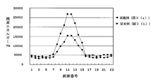
- FIG. 4 shows a graph in which the pixel in the arrow direction in the circle in FIG. 3 is plotted on the horizontal axis and the pixel energy Ve is plotted on the vertical axis.
- the example shows that the edge of the wire is clearer than the conventional example. Further, it can be seen from the graph that the pixel energy Ve is calculated to be larger in the embodiment than in the conventional example, and the structure recognition can be enhanced from this point.
- FIG. 5 is an image after the noise suppression processing
- (a) is an image according to the embodiment
- (b) is an image according to a conventional example.
- an anisotropic filter is applied that smoothes only in the longitudinal direction while leaving an edge along the longitudinal direction of the wire, which can be determined by the pixel energy Ve.
- the wire edge is clear, and it can be seen that the breakage of the wire is suppressed as compared with the conventional example.
- band images having different frequency bands are obtained, and the maximum value among the absolute values of the gradient components in different directions in each pixel of interest is calculated as the pixel energy Ve of the pixel of interest.
- the absolute value average of the magnitudes of the gradient components in a plurality of directions is not obtained as in the conventional example, but the maximum value is calculated as the pixel energy Ve. Therefore, the pixel energy Ve is calculated larger than in the conventional example. That is, a signal corresponding to a structural portion in the input image can be strongly recognized. Accordingly, since noise suppression is performed on the input image based on the pixel energy Ve, noise processing in the input image can be performed by increasing noise suppression other than the portion recognized as the structure or weakening noise suppression in the portion recognized as the structure. Can be easily controlled. As a result, the quality of the input image can be improved.
- the pixel energy Ve may be calculated smaller than in the present invention. Therefore, the noise suppression degree in step S5 in FIG. 1 is calculated to be small, and the edge reliability in step S6 is calculated to be low. Then, in step S10, switching between the isotropic filter and the anisotropic filter may be inappropriate, and as a result, a portion where the edge becomes sweet in the edge smooth image is generated. Moreover, the case where the weighting subtraction in step S11 becomes inappropriate may occur. Accordingly, the noise component of the noise image may include a part of the structure portion. As a result, the structure portion may be subtracted during the noise subtraction step S14, and the structure portion may be missing in the processed image.
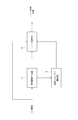
- FIG. 6 is a block diagram illustrating a schematic configuration of the image processing apparatus according to the embodiment.
- This image processing apparatus is provided in, for example, an X-ray fluoroscopic apparatus or an X-ray imaging apparatus.
- the image processing apparatus includes a band image generation unit 1, a pixel energy calculation unit 3, and a noise suppression unit 5.
- the band image generation unit 1 corresponds to the “band image generation unit” in the present invention
- the pixel energy calculation unit 3 corresponds to the “pixel energy calculation unit” in the present invention
- the noise suppression unit 5 corresponds to the “noise” in the present invention. It corresponds to “suppressing means”.
- the band image generation unit 1 takes in an input image and performs the above-described band division (step S1).
- the pixel energy calculation unit 3 calculates the pixel energy Ve based on the above-described formula for each band image.
- the noise suppression unit 5 performs the processing from steps S4 to S14 including steps PP1 and PP2 described above, and outputs a noise suppression image.
- the output noise-suppressed image is output to a display device (not shown) or stored in a storage device, for example.
- the above-described image processing method can be suitably implemented.
- the present invention is not limited to the above embodiment, and can be modified as follows.
- the gradient components are obtained in four directions, but gradient components in eight directions or more may be obtained in accordance with the arithmetic processing capability. Thereby, the direction of a structure can be calculated
- the present invention is suitable for an image processing method and apparatus for suppressing noise components in an X-ray image.
Landscapes
- Engineering & Computer Science (AREA)
- Physics & Mathematics (AREA)
- Health & Medical Sciences (AREA)
- Life Sciences & Earth Sciences (AREA)
- Medical Informatics (AREA)
- General Physics & Mathematics (AREA)
- Theoretical Computer Science (AREA)
- Pathology (AREA)
- Molecular Biology (AREA)
- Biophysics (AREA)
- Nuclear Medicine, Radiotherapy & Molecular Imaging (AREA)
- Optics & Photonics (AREA)
- Computer Vision & Pattern Recognition (AREA)
- Radiology & Medical Imaging (AREA)
- Biomedical Technology (AREA)
- Heart & Thoracic Surgery (AREA)
- High Energy & Nuclear Physics (AREA)
- Surgery (AREA)
- Animal Behavior & Ethology (AREA)
- General Health & Medical Sciences (AREA)
- Public Health (AREA)
- Veterinary Medicine (AREA)
- Apparatus For Radiation Diagnosis (AREA)
- Image Processing (AREA)
Abstract
それぞれ異なる周波数帯域の帯域画像を求め、各注目画素におけるそれぞれ異なる複数方向の勾配成分の大きさの絶対値のうち、最大のものを注目画素の画素エネルギーとして算出する。従来例のように、複数方向の勾配成分の大きさの絶対値平均を求めるのではなく、最大のものを画素エネルギーとして算出する。したがって、従来例に比較して画素エネルギーが大きく算出されることになる。つまり、入力画像における構造部分に相当する信号を強く認識することができる。したがって、画素エネルギーに基づいて入力画像に対するノイズ抑制を行うので、構造として認識した部分以外のノイズ抑制を強めたり、構造として認識した部分のノイズ抑制を弱めたりすることで、入力画像におけるノイズ処理の制御を容易に行うことができる。その結果、入力画像の品質を向上させることができる。
Description
この発明は、X線画像中のノイズ成分を抑制する画像処理方法及びその装置に係り、特に、X線画像中の構造の認識に関する。
従来のこの種の画像処理方法として、まず、入力画像(例えば、X線透視画像)から複数の帯域画像を作成する。そして、複数の帯域画像において、各画素を注目画素としつつ、注目画素ごとに画素エネルギーを算出する。この画素エネルギーは、入力画像中に存在する構造の大きさ(平坦度の逆)を表すのに用いられる指標値である。次に、指標値を用いて帯域画像ごとにノイズを抑制するための処理を行い、入力画像におけるノイズを抑制している(例えば、特許文献1参照)。例えば、構造及びその付近では、ノイズが少ないのでノイズ抑制を弱くし、その他の領域ではノイズ抑制を強くするようなノイズ抑制処理が行われる。
上述した画素エネルギーをVeとし、勾配をnとし、勾配nをそれぞれ異なる方向として、各方向を0,1,2,3で表し、帯域画像の画素値をSBとし、各帯域画像をmとし、mを1~6の番号で表すと、画素エネルギーVeは、具体的には次の式で算出されている。
q’n,m=GradientFiltern(SBm)
qn,m=GaussFiltern(|q’n,m|)
Vem[i]=(q0,m[i]+q1,m[i]+q2,m[i]+q3,m[i])/4
q’n,m=GradientFiltern(SBm)
qn,m=GaussFiltern(|q’n,m|)
Vem[i]=(q0,m[i]+q1,m[i]+q2,m[i]+q3,m[i])/4
まず、例えば、0°、45°、90°、135°の4方向の勾配フィルタを帯域画像に適用して、注目画素における4方向の勾配の各成分をq’n,mとして算出する。次に、各注目画素について4方向の各成分の絶対値に対してガウスフィルタを適用して各方向成分の大きさをqn,mとして算出する。次に、各注目画素における各方向成分の大きさの平均値を求め、これを画素ごとの画素エネルギーVeとして求めている。
特開2004-242285号公報
一般的に、線量が少ない条件でのX線透視画像、及び線量が少ないX線撮影画像では、線量が多い条件でのX線透視画像や、線量が多いX線撮影画像と比較すると、信号強度が弱く、かつノイズ強度が強くなる。したがって、X線画像中における構造を示す信号と、ノイズを表す信号とを区別することが困難になる。そのため、上述した従来例では、画素の4方向の勾配について絶対値平均をとることによって、ノイズ成分を信号として誤検出してしまうことを低減している。しかしながら、線量が多い条件でのX線透視画像、及び線量が多いX線撮影画像であっても、画像中にワイヤが存在している部分の構造認識が弱くなるので、つながっているワイヤが途切れたように見えることがあるという問題がある。
なお、上述したワイヤは、例えば、カテーテルを用いた術式において、カテーテルに先行して挿入されるガイドワイヤのことである。したがって、X線透視画像においてワイヤが途切れたように見えたり、つながっているように見えたりして、カテーテル操作に支障を生じる恐れがあるので、構造認識が弱くなると問題となる。
ここで、図7を参照する。なお、図7は、従来例によるノイズ抑制処理後のX線撮影画像であり、(a)は全体図であり、(b)は一部拡大図である。
図7(a)は、数枚のアクリル板を積層するとともに、階段状となるように位置をずらして配置し、その最上面にワイヤを配置した状態で撮影したX線撮影画像である。図7(b)の拡大部に示すように、連続しているはずのワイヤが一部途切れて見えている。
この発明は、このような事情に鑑みてなされたものであって、アルゴリズムを工夫することにより、構造認識を高めることができる画像処理方法及びその装置を提供することを目的とする。
この発明は、このような目的を達成するために、次のような構成をとる。
すなわち、この発明の画像処理方法は、X線画像のノイズを抑制する画像処理方法において、それぞれ異なる周波数帯域の帯域画像を入力画像から生成する帯域画像生成過程と、帯域画像ごとに、各注目画素におけるそれぞれ異なる複数方向の勾配成分の大きさの絶対値のうち、最大のものを注目画素の画素エネルギーとして算出する画素エネルギー算出過程と、前記画素エネルギーに基づいて入力画像に対するノイズ抑制を行うノイズ抑制過程と、を備えていることを特徴とするものである。
すなわち、この発明の画像処理方法は、X線画像のノイズを抑制する画像処理方法において、それぞれ異なる周波数帯域の帯域画像を入力画像から生成する帯域画像生成過程と、帯域画像ごとに、各注目画素におけるそれぞれ異なる複数方向の勾配成分の大きさの絶対値のうち、最大のものを注目画素の画素エネルギーとして算出する画素エネルギー算出過程と、前記画素エネルギーに基づいて入力画像に対するノイズ抑制を行うノイズ抑制過程と、を備えていることを特徴とするものである。
[作用・効果]この発明によれば、帯域画像生成過程において、それぞれ異なる周波数帯域の帯域画像を入力画像から求め、画素エネルギー算出過程において、各注目画素におけるそれぞれ異なる複数方向の勾配成分の大きさの絶対値のうち、最大のものを注目画素の画素エネルギーとして算出する。従来例のように、複数方向の勾配成分の大きさの絶対値平均を求めるのではなく、最大のものを画素エネルギーとして算出する。したがって、従来例に比較して画素エネルギーが大きく算出されることになる。つまり、入力画像における構造部分に相当する信号を強く認識することができる。したがって、ノイズ抑制過程において、画素エネルギーに基づいて入力画像に対するノイズ抑制を行うので、構造として認識した部分以外のノイズ抑制を強めたり、構造として認識した部分のノイズ抑制を弱めたりすることで、入力画像におけるノイズ処理の制御を容易に行うことができる。その結果、入力画像の品質を向上させることができる。
また、この発明において、前記画素エネルギー算出過程は、前記勾配成分の複数方向を4方向とすることが好ましい。勾配成分の複数方向を4方向に限定することにより、演算負荷を軽減することができる。
また、この発明において、前記ノイズ抑制過程は、前記入力画像と、予め設定された基準線量値に応じた信号値-線量変換とに基づいて線量を求め、この線量と前記画素エネルギーとに基づいて算出されるノイズ抑制度を用いることが好ましい。構造部分では画素エネルギーが大きく算出されるので、構造部分とそれ以外との区別が容易になり、ノイズ抑制度も適切に算出できる。したがって、ノイズ抑制度を用いることにより、ノイズ処理を適切に行うことができる。
この発明は、X線画像のノイズを抑制する画像処理装置において、X線画像のノイズを抑制する画像処理装置において、それぞれ異なる周波数帯域の帯域画像を入力画像から生成する帯域画像生成手段と、帯域画像ごとに、各注目画素におけるそれぞれ異なる複数方向の勾配成分の大きさの絶対値のうち、最大のものを注目画素の画素エネルギーとして算出する画素エネルギー算出手段と、前記画素エネルギーに基づいて入力画像に対するノイズ抑制を行うノイズ抑制手段と、を備えていることを特徴とするものである。
[作用・効果]この発明によれば、帯域画像生成手段は、それぞれ異なる周波数帯域の帯域画像を入力画像から求め、画素エネルギー算出手段は、各注目画素におけるそれぞれ異なる複数方向の勾配成分の大きさの絶対値のうち、最大のものを注目画素の画素エネルギーとして算出する。従来例のように、複数方向の勾配成分の大きさの絶対値平均を求めるのではなく、最大のものを画素エネルギーとして算出する。したがって、従来例に比較して画素エネルギーが大きく算出されることになる。つまり、入力画像における構造部分に相当する信号が強く認識される。したがって、ノイズ抑制手段は、画素エネルギーに基づいて入力画像に対するノイズ抑制を行うので、構造として認識した部分以外のノイズ抑制を強めたり、構造として認識した部分のノイズ抑制を弱めたりすることで、入力画像におけるノイズ処理の制御を容易に行うことができる。その結果、入力画像の品質を向上させることができる。
また、この発明において、前記画素エネルギー算出手段は、前記勾配成分の複数方向を4方向とすることが好ましい。勾配成分の複数方向を4方向に限定することにより、画素エネルギー算出手段における演算負荷を軽減することができる。
また、この発明において、前記ノイズ抑制手段は、前記入力画像と、予め設定された基準線量値に応じた信号値-線量変換とに基づいて線量を求め、この線量と前記画素エネルギーとに基づいて算出されるノイズ抑制度を用いることが好ましい。構造部分では画素エネルギーが大きく算出されるので、構造部分とそれ以外との区別が容易になり、ノイズ抑制度も適切に算出できる。したがって、ノイズ抑制度を用いることにより、ノイズ抑制手段によるノイズ処理を適切に行うことができる。
この発明に係る画像処理方法によれば、帯域画像生成過程において、それぞれ異なる周波数帯域の帯域画像を求め、画素エネルギー算出過程において、各注目画素におけるそれぞれ異なる複数方向の勾配成分の大きさの絶対値のうち、最大のものを注目画素の画素エネルギーとして算出する。従来例のように、複数方向の勾配成分の大きさの絶対値平均を求めるのではなく、最大のものを画素エネルギーとして算出する。したがって、従来例に比較して画素エネルギーが大きく算出されることになる。つまり、入力画像における構造部分に相当する信号を強く認識することができる。したがって、ノイズ抑制過程において、画素エネルギーに基づいて入力画像に対するノイズ抑制を行うので、構造として認識した部分以外のノイズ抑制を強めたり、構造として認識した部分のノイズ抑制を弱めたりすることで、入力画像におけるノイズ処理の制御を容易に行うことができる。その結果、入力画像の品質を向上させることができる。
Ve … 画素エネルギー
1 … 帯域画像生成部
3 … 画素エネルギー算出部
5 … ノイズ抑制部
1 … 帯域画像生成部
3 … 画素エネルギー算出部
5 … ノイズ抑制部
<画像処理方法>
以下、図面を参照してこの発明の一実施例を説明する。なお、図1は、実施例に係る画像処理方法体の流れを説明するための模式図であり、図2は、勾配フィルタの一例を示す模式図である。図1中における実線矢印は画像の流れを示し、点線矢印は特徴量の流れを示す。
以下、図面を参照してこの発明の一実施例を説明する。なお、図1は、実施例に係る画像処理方法体の流れを説明するための模式図であり、図2は、勾配フィルタの一例を示す模式図である。図1中における実線矢印は画像の流れを示し、点線矢印は特徴量の流れを示す。
実施例に係る画像処理方法は、X線撮影画像またはX線透視画像を処理対象である入力画像として取り扱う。まずは、入力画像を対象にして、それぞれ異なる複数の周波数帯域を有する帯域画像(帯域制限画像ともいう)として生成する(ステップS1)。具体な生成方法としては、例えば、ラプラシアンピラミッド分解による生成方法が挙げられる。この他に、帯域画像の生成には、ウェーブレット変換などの多重解像度変換による生成方法を採用することができる。
次に、各帯域画像に勾配フィルタを適用し、各帯域画像の各画素を順に注目画素として、それぞれ異なる方向の勾配成分を注目画素ごとに求める(ステップS2)。この勾配成分は、注目画素の画素値と、注目画素からある方向に位置する画素の画素値との差であり、画素値の差と方向とからなる成分を表す。例えば、帯域画像において画素値の差が大きな方向においては、勾配成分が大きくなり、画素値の差が小さな方向においては、勾配成分が小さくなる。具体的には、例えば、図2に示すように、それぞれ異なる4方向の勾配成分を求める勾配フィルタ(GradientFilter)を適用する。図2は、0°、45°、90°、135°の勾配フィルタの例であって、31×31画素の空間フィルタの場合を例示している。勾配フィルタを構成するマトリクスの大きさは、演算処理能力や所望の精度に応じて適宜に設定すればよい。例えば、6つの周波数帯域を有する帯域画像を生成している場合、周波数帯域ごとの画像に番号m(mは、例えば、1~6)を付し、各帯域画像の画素値をSBとし、各勾配フィルタの番号をn(nは、例えば、1~4)とすると、次式で勾配成分q’n,mを求める。
q’n,m=GradientFiltern(SBm)
上記のGradientFilterは、一次微分フィルタの一種である。このフィルタは、画素値の差が大きいほど、より強調することになり、このフィルタで求められた値は、エッジの強さを表す。
次に、各注目画素における各方向成分の大きさqn,mを求める。
qn,m=GaussFiltern(|q’n,m|)
そして、上記の各方向成分の大きさqn,mを次式に適用して、画素エネルギーVeを各画素iについて算出する(ステップS3)。
Vem[i]=Max(q0,m[i],q1,m[i],q2,m[i],q3,m[i])
なお、Maxは、括弧内における各方向成分の大きさqn,m[i]のうち最大のものを選択することを表している。
画素エネルギーVeは、各帯域画像の各画素位置(注目画素)において、それぞれ異なる4方向の勾配成分の大きさの絶対値のうち、最大のものとして算出する。この画素エネルギーVeは、その画素が画像中の構造の大きさ(平坦度の逆)を表しており、値が大きい程、画像中における構造である確率が高いことを示す。
画素エネルギーVeとは別に、各注目画素における各方向成分の大きさqn,mを用いて、エッジの方向を示す勾配ベクトルを算出しておく(ステップS4)。勾配ベクトルを算出するのは、画素エネルギーVeが絶対値をとって算出されるので、大きさを判断することはできるが、方向を判断することができないからである。なお、ここでいう勾配ベクトルとは、方向及びその大きさを示すものであり(qn,m[i])、上述した4方向の勾配フィルタを用いた場合には、0°、45°、90°、135°の4方向における大きさを示す。
画素エネルギーVeと、予め決められた基準線量値(ステップPP1)と、入力画像と、基準線量値に応じた信号値-線量変換(ステップPP2)とから線量を求め、線量と画素エネルギーVeとに基づいてノイズ抑制度を算出する(ステップS5)。なお、基準線量値は、X線を照射可能な線量の範囲のうち、予め設定された任意の線量値を表す。例えば、基準線量値は、X線撮影やX線透視などの手技や、胸部や腹部などのX線の照射部位により異なる値に設定されるものである。画像を得る際の線量値が基準線量値よりも小さい場合には、画像が暗くなり、ノイズが増える。一方、画像を得る際の線量値が基準線量値よりも小さい場合には、画像が明るくなり、ノイズが減る。信号値-線量変換は、信号値に相当する画素値と、信号値を生じる線量との対応関係を示した基準線量値ごとのテーブルである。また、ノイズ抑制度は、ノイズ除去の度合いを表し、線量が少ないとノイズ成分が多く、かつ、画素エネルギーVeが小さいとノイズ成分が多く、線量が多いとノイズ成分が少なく、かつ、画素エネルギーVeが大きいとノイズ成分が少ないという特性と、画素値に対応する信号値と基準線量値との関係とを考慮して決定される。
さらに、画素エネルギーVeと、エッジの方向及びその大きさを示す勾配ベクトルqn,m[i]とに基づいて、エッジの確からしさを表すエッジ信頼性を各画素について算出する(ステップS6)。エッジ信頼性は、例えば、勾配ベクトルqn,m[i]が大きく、しかも画素エネルギーVeが大きい場合には、その画素が構造を表している確率が高いことを示す。さらに、勾配ベクトルqn,m[i]のうち、その大きさが大きなものの方向に基づいて、画素値を平滑化すべき方向を表す平滑化方向を算出する(ステップS7)。この平滑化方向は、エッジを構成する確度が高い画素群が平滑化されないようにするために算出される。
次に、各帯域画像に等方性フィルタを適用する(ステップS8)。等方性フィルタは、画像を平滑化して、ノイズ成分を除去することになるので、帯域画像のノイズ成分の大きさに応じて変える必要がある。そこで、等方性フィルタは、帯域画像の周波数、及び基準線量値の関係に応じて適用する。また、各帯域画像に異方性フィルタを適用する(ステップS9)。異方性フィルタは、帯域画像のエッジが平滑されないようにエッジ方向に平滑化を行う。また、異方性フィルタも、帯域画像のノイズ成分の大きさに応じて変えるために、基準線量値との関係に応じて適用する。この処理により、帯域画像のエッジが強調された画像が生成される。それらの結果を加算するが、その際にエッジ信頼性を考慮して重み付け加算(エッジ抽出)を行い(ステップS10)、エッジ以外が平滑化された帯域画像ごとのエッジ平滑化画像を生成する。つまり、エッジ信頼性を用いて、エッジらしい部分には異方性フィルタを適用し、その他の部分には等方性フィルタを適用する重み付けを行うことにより、エッジを残してそれ以外を平滑化する。
次に、ノイズ抑制度または、ノイズ抑制度及びエッジ信頼性に応じて重み付けを行い、各帯域画像に対して、対応するエッジ平滑化画像を減算(エッジ除外)する(ステップS11)。ノイズ抑制度は、画素値に応じたノイズ除去の度合いを示し、エッジ信頼性は、画素のエッジの確からしさを示しているので、これらに応じて画素ごとに重み付けを変えて、ノイズ画像におけるノイズ成分の強弱をコントロールする。例えば、ノイズ抑制度が高い部分でエッジ信頼性が低い部分は、ノイズ成分が多いので、エッジ平滑画像では平滑されている。そこで、画素値を大きくする重み付けを行うと、減算した際にノイズ画像におけるノイズ成分を小さくできる。これにより、各帯域画像からエッジ部分(構造)が除外され、帯域画像ごとにエッジのないノイズ画像が生成される。ここで重み付け減算を行うことは、後述するステップS14におけるノイズ減算の結果に影響を与え、その結果、処理後画像におけるノイズ成分の抑制度合いにも影響を与える。
なお、上記の重み付けは、ノイズ抑制度とエッジ信頼性の両方を使用した方がノイズ画像におけるノイズ成分のコントロール精度を高くすることができる。しかし、ノイズ抑制度だけを用いてエッジ信頼性を使用しなくてもよい。これにより、演算の負荷を軽減することができる。
帯域画像ごとのノイズ画像に基づき帯域合成を行い(ステップS12)、帯域合成したノイズ画像について、入力画像の濃度に応じた階調補正を行う濃度依存性係数処理を行う(ステップS13)。次に、入力画像から濃度依存性係数処理を終えたノイズ画像を減算するノイズ減算を行う(ステップS14)。これにより入力画像からノイズ成分が抑制された処理後画像が得られる。
なお、ステップS1がこの発明における「帯域画像生成過程」に相当し、ステップS3がこの発明における「画素エネルギー算出過程」に相当し、ステップS4~S14がこの発明における「ノイズ抑制過程」に相当する。
ここで、算出した画素エネルギーVeに基づく画像を実施例と従来例とで比較すると、図3のようになる。また、図3中の丸内における矢印方向の画素を横軸にとり、画素エネルギーVeを縦軸にとってグラフ化すると図4のようになる。
実施例は、従来例に比較してワイヤのエッジが明瞭になっていることがわかる。また、グラフから、実施例は、従来例に比較して画素エネルギーVeが大きく算出されており、この点からも構造認識を高くできていることがわかる。
次に、上述した方法により得られたノイズ抑制画像を比較する。図5は、ノイズ抑制処理後の画像であり、(a)は実施例による画像であり、(b)は従来例による画像である。なお、ノイズ抑制の際には、画素エネルギーVeにより判別できたワイヤの長手方向に沿って、エッジを残しながら長手方向にのみ平滑化する異方性フィルタを施してある。
図5に示すように、実施例は、ワイヤのエッジが明瞭になっており、従来例に比較してワイヤの途切れが抑制されていることがわかる。
この実施例によると、それぞれ異なる周波数帯域の帯域画像を求め、各注目画素におけるそれぞれ異なる複数方向の勾配成分の大きさの絶対値のうち、最大のものを注目画素の画素エネルギーVeとして算出する。従来例のように、複数方向の勾配成分の大きさの絶対値平均を求めるのではなく、最大のものを画素エネルギーVeとして算出する。したがって、従来例に比較して画素エネルギーVeが大きく算出されることになる。つまり、入力画像における構造部分に相当する信号を強く認識することができる。したがって、画素エネルギーVeに基づいて入力画像に対するノイズ抑制を行うので、構造として認識した部分以外のノイズ抑制を強めたり、構造として認識した部分のノイズ抑制を弱めたりすることで、入力画像におけるノイズ処理の制御を容易に行うことができる。その結果、入力画像の品質を向上できる。
なお、従来例では、画素エネルギーVeが本発明よりも小さく算出されることがある。したがって、図1におけるステップS5のノイズ抑制度が小さく算出され、ステップS6におけるエッジ信頼性が低く算出されることになる。すると、ステップS10において等方性フィルタと異方性フィルタの切り換えが不適切となる場合が生じ、その結果、エッジ平滑画像においてエッジが甘くなる部分が生じる。また、ステップS11における重み付け減算が不適切となる場合も生じ得る。したがって、ノイズ画像のノイズ成分が構造部分の一部を含む場合も生じ得る。その結果、ノイズ減算のステップS14の際に構造部分も減算されることがあり、処理後画像において構造部分の欠けが生じる恐れがある。
<画像処理装置>
次に、上述した画像処理方法を実施する画像処理装置について、図6を参照して説明する。なお、図6は、実施例に係る画像処理装置の概略構成を示すブロック図である。
次に、上述した画像処理方法を実施する画像処理装置について、図6を参照して説明する。なお、図6は、実施例に係る画像処理装置の概略構成を示すブロック図である。
この画像処理装置は、例えば、X線透視撮影装置やX線撮像装置に備えられる。画像処理装置は、帯域画像生成部1と、画素エネルギー算出部3と、ノイズ抑制部5とを備えている。
なお、帯域画像生成部1がこの発明における「帯域画像生成手段」に相当し、画素エネルギー算出部3がこの発明における「画素エネルギー算出手段」に相当し、ノイズ抑制部5がこの発明における「ノイズ抑制手段」に相当する。
帯域画像生成部1は、入力画像を取り込んで、上述した帯域分割(ステップS1)を行う。画素エネルギー算出部3は、各帯域画像について上述した式に基づいて画素エネルギーVeを算出する。ノイズ抑制部5は、上述したステップPP1,2を含むステップS4~S14までの処理を行って、ノイズ抑制画像を出力する。出力されたノイズ抑制画像は、例えば、図示しない表示装置に出力されたり、記憶装置に記憶されたりする。
この実施例装置によると、上述した画像処理方法を好適に実施することができる。
この発明は、上記実施形態に限られることはなく、下記のように変形実施することができる。
(1)上述した実施例では勾配成分を4方向について求めたが、演算処理能力に応じて8方向以上の勾配成分を求めるようにしてもよい。これにより、構造の方向を細かく求めることができ、構造の認識を向上させることができる。
(2)上述した実施例では帯域画像を6つとしたが、演算処理能力に応じて7つ以上の帯域画像を求めるようにしてもよい。これにより、ノイズの抑制度を高くすることができる。
以上のように、この発明は、X線画像中のノイズ成分を抑制する画像処理方法及びその装置に適している。
Claims (6)
- X線画像のノイズを抑制する画像処理方法において、
それぞれ異なる周波数帯域の帯域画像を入力画像から生成する帯域画像生成過程と、
帯域画像ごとに、各注目画素におけるそれぞれ異なる複数方向の勾配成分の大きさの絶対値のうち、最大のものを注目画素の画素エネルギーとして算出する画素エネルギー算出過程と、
前記画素エネルギーに基づいて入力画像に対するノイズ抑制を行うノイズ抑制過程と、
を備えていることを特徴とする画像処理方法。 - 請求項1に記載の画像処理方法において、
前記画素エネルギー算出過程は、前記勾配成分の複数方向を4方向とすることを特徴とする画像処理方法。 - 請求項1または2に記載の画像処理方法において、
前記ノイズ抑制過程は、前記入力画像と、予め設定された基準線量値に応じた信号値-線量変換とに基づいて線量を求め、この線量と前記画素エネルギーとに基づいて算出されるノイズ抑制度を用いることを特徴とする画像処理方法。 - X線画像のノイズを抑制する画像処理装置において、
それぞれ異なる周波数帯域の帯域画像を入力画像から生成する帯域画像生成手段と、
帯域画像ごとに、各注目画素におけるそれぞれ異なる複数方向の勾配成分の大きさの絶対値のうち、最大のものを注目画素の画素エネルギーとして算出する画素エネルギー算出手段と、
前記画素エネルギーに基づいて入力画像に対するノイズ抑制を行うノイズ抑制手段と、
を備えていることを特徴とする画像処理装置。 - 請求項4に記載の画像処理装置において、
前記画素エネルギー算出手段は、前記勾配成分の複数方向を異なる4方向とすることを特徴とする画像処理装置。 - 請求項4または5に記載の画像処理装置において、
前記ノイズ抑制手段は、前記入力画像と、予め設定された基準線量値に応じた信号値-線量変換とに基づいて線量を求め、この線量と前記画素エネルギーとに基づいて算出されるノイズ抑制度を用いることを特徴とする画像処理装置。
Priority Applications (1)
| Application Number | Priority Date | Filing Date | Title |
|---|---|---|---|
| PCT/JP2011/003319 WO2012168985A1 (ja) | 2011-06-10 | 2011-06-10 | 画像処理方法及びその装置 |
Applications Claiming Priority (1)
| Application Number | Priority Date | Filing Date | Title |
|---|---|---|---|
| PCT/JP2011/003319 WO2012168985A1 (ja) | 2011-06-10 | 2011-06-10 | 画像処理方法及びその装置 |
Publications (1)
| Publication Number | Publication Date |
|---|---|
| WO2012168985A1 true WO2012168985A1 (ja) | 2012-12-13 |
Family
ID=47295595
Family Applications (1)
| Application Number | Title | Priority Date | Filing Date |
|---|---|---|---|
| PCT/JP2011/003319 Ceased WO2012168985A1 (ja) | 2011-06-10 | 2011-06-10 | 画像処理方法及びその装置 |
Country Status (1)
| Country | Link |
|---|---|
| WO (1) | WO2012168985A1 (ja) |
Cited By (3)
| Publication number | Priority date | Publication date | Assignee | Title |
|---|---|---|---|---|
| JP2016527935A (ja) * | 2013-06-28 | 2016-09-15 | タレス | 蛍光透視画像シーケンスにおけるノイズを減らす方法 |
| WO2023024660A1 (zh) * | 2021-08-23 | 2023-03-02 | 深圳前海微众银行股份有限公司 | 一种图像增强的方法及装置 |
| CN116894794A (zh) * | 2023-09-11 | 2023-10-17 | 长沙超创电子科技有限公司 | 一种视频的快速去噪方法 |
Citations (4)
| Publication number | Priority date | Publication date | Assignee | Title |
|---|---|---|---|---|
| JP2001057677A (ja) * | 1999-06-10 | 2001-02-27 | Fuji Photo Film Co Ltd | 画像処理方法および装置並びに記録媒体 |
| JP2003534754A (ja) * | 2000-05-23 | 2003-11-18 | コーニンクレッカ フィリップス エレクトロニクス エヌ ヴィ | ディジタル画像中の糸状構造を全体的に抽出する画像処理方法、システム及び検査装置 |
| JP2004242285A (ja) * | 2003-01-14 | 2004-08-26 | Fuji Photo Film Co Ltd | ノイズ抑制処理方法および装置並びにプログラム |
| JP2005021456A (ja) * | 2003-07-03 | 2005-01-27 | Fuji Photo Film Co Ltd | 放射線画像用画像処理装置、方法およびプログラム |
-
2011
- 2011-06-10 WO PCT/JP2011/003319 patent/WO2012168985A1/ja not_active Ceased
Patent Citations (4)
| Publication number | Priority date | Publication date | Assignee | Title |
|---|---|---|---|---|
| JP2001057677A (ja) * | 1999-06-10 | 2001-02-27 | Fuji Photo Film Co Ltd | 画像処理方法および装置並びに記録媒体 |
| JP2003534754A (ja) * | 2000-05-23 | 2003-11-18 | コーニンクレッカ フィリップス エレクトロニクス エヌ ヴィ | ディジタル画像中の糸状構造を全体的に抽出する画像処理方法、システム及び検査装置 |
| JP2004242285A (ja) * | 2003-01-14 | 2004-08-26 | Fuji Photo Film Co Ltd | ノイズ抑制処理方法および装置並びにプログラム |
| JP2005021456A (ja) * | 2003-07-03 | 2005-01-27 | Fuji Photo Film Co Ltd | 放射線画像用画像処理装置、方法およびプログラム |
Cited By (4)
| Publication number | Priority date | Publication date | Assignee | Title |
|---|---|---|---|---|
| JP2016527935A (ja) * | 2013-06-28 | 2016-09-15 | タレス | 蛍光透視画像シーケンスにおけるノイズを減らす方法 |
| WO2023024660A1 (zh) * | 2021-08-23 | 2023-03-02 | 深圳前海微众银行股份有限公司 | 一种图像增强的方法及装置 |
| CN116894794A (zh) * | 2023-09-11 | 2023-10-17 | 长沙超创电子科技有限公司 | 一种视频的快速去噪方法 |
| CN116894794B (zh) * | 2023-09-11 | 2023-11-21 | 长沙超创电子科技有限公司 | 一种视频的快速去噪方法 |
Similar Documents
| Publication | Publication Date | Title |
|---|---|---|
| JP6071444B2 (ja) | 画像処理装置及びその作動方法、プログラム | |
| JP5918198B2 (ja) | 超音波診断装置 | |
| JP5037705B2 (ja) | 画像処理装置および方法並びにプログラム | |
| KR101312459B1 (ko) | 의료영상의 잡음 저감 방법 | |
| EP2355039A1 (en) | Image generating apparatus and method for emphasizing edge based on image characteristics | |
| US10475181B2 (en) | Image processing apparatus, image processing method, and image processing program | |
| KR102301379B1 (ko) | 영상 처리 장치, 영상 촬영 장치, 영상 처리 방법 및 영상 촬영 장치의 제어 방법 | |
| WO2011155867A1 (ru) | Способ коррекции цифровых изображений | |
| US10143432B2 (en) | X-ray apparatus and control method for the same | |
| JP6897585B2 (ja) | 放射線画像処理装置、散乱線補正方法及びプログラム | |
| JP2004242285A (ja) | ノイズ抑制処理方法および装置並びにプログラム | |
| JP6678541B2 (ja) | 画像処理装置、方法およびプログラム | |
| EP3232932B1 (en) | Motion correction method in dual energy radiography | |
| CN105723416A (zh) | 图像降噪方法 | |
| WO2012168985A1 (ja) | 画像処理方法及びその装置 | |
| JPWO2019053935A1 (ja) | 放射線撮影装置 | |
| US9501711B2 (en) | Image processing method and image processing device with correction of pixel statistical values to reduce random noise | |
| JP6002324B2 (ja) | 放射線画像生成装置及び画像処理方法 | |
| JP5614550B2 (ja) | 画像処理方法、画像処理装置及びプログラム | |
| CN111489314A (zh) | 图像增强方法、装置及终端设备 | |
| JP6256703B2 (ja) | 画像処理方法、及び画像処理装置 | |
| US8792747B2 (en) | Image processing method and device, and medical imaging instrument | |
| EP2843617B1 (en) | Image processing method and image processing device | |
| JP6926856B2 (ja) | 放射線画像処理装置、プログラム及び放射線画像処理方法 | |
| JP4648658B2 (ja) | 医用画像処理装置 |
Legal Events
| Date | Code | Title | Description |
|---|---|---|---|
| 121 | Ep: the epo has been informed by wipo that ep was designated in this application |
Ref document number: 11867217 Country of ref document: EP Kind code of ref document: A1 |
|
| NENP | Non-entry into the national phase |
Ref country code: DE |
|
| 122 | Ep: pct application non-entry in european phase |
Ref document number: 11867217 Country of ref document: EP Kind code of ref document: A1 |
|
| NENP | Non-entry into the national phase |
Ref country code: JP |