WO2012165827A2 - 마사지기 - Google Patents
마사지기 Download PDFInfo
- Publication number
- WO2012165827A2 WO2012165827A2 PCT/KR2012/004196 KR2012004196W WO2012165827A2 WO 2012165827 A2 WO2012165827 A2 WO 2012165827A2 KR 2012004196 W KR2012004196 W KR 2012004196W WO 2012165827 A2 WO2012165827 A2 WO 2012165827A2
- Authority
- WO
- WIPO (PCT)
- Prior art keywords
- massage
- raw material
- lid
- skin
- vibration
- Prior art date
- Legal status (The legal status is an assumption and is not a legal conclusion. Google has not performed a legal analysis and makes no representation as to the accuracy of the status listed.)
- Ceased
Links
Images



Classifications
-
- A—HUMAN NECESSITIES
- A61—MEDICAL OR VETERINARY SCIENCE; HYGIENE
- A61H—PHYSICAL THERAPY APPARATUS, e.g. DEVICES FOR LOCATING OR STIMULATING REFLEX POINTS IN THE BODY; ARTIFICIAL RESPIRATION; MASSAGE; BATHING DEVICES FOR SPECIAL THERAPEUTIC OR HYGIENIC PURPOSES OR SPECIFIC PARTS OF THE BODY
- A61H23/00—Percussion or vibration massage, e.g. using supersonic vibration; Suction-vibration massage; Massage with moving diaphragms
- A61H23/02—Percussion or vibration massage, e.g. using supersonic vibration; Suction-vibration massage; Massage with moving diaphragms with electric or magnetic drive
- A61H23/0218—Percussion or vibration massage, e.g. using supersonic vibration; Suction-vibration massage; Massage with moving diaphragms with electric or magnetic drive with alternating magnetic fields producing a translating or oscillating movement
-
- A—HUMAN NECESSITIES
- A45—HAND OR TRAVELLING ARTICLES
- A45D—HAIRDRESSING OR SHAVING EQUIPMENT; EQUIPMENT FOR COSMETICS OR COSMETIC TREATMENTS, e.g. FOR MANICURING OR PEDICURING
- A45D34/00—Containers or accessories specially adapted for handling liquid toiletry or cosmetic substances, e.g. perfumes
- A45D34/04—Appliances specially adapted for applying liquid, e.g. using roller or ball
- A45D34/041—Appliances specially adapted for applying liquid, e.g. using roller or ball using a roller, a disc or a ball
-
- A—HUMAN NECESSITIES
- A45—HAND OR TRAVELLING ARTICLES
- A45D—HAIRDRESSING OR SHAVING EQUIPMENT; EQUIPMENT FOR COSMETICS OR COSMETIC TREATMENTS, e.g. FOR MANICURING OR PEDICURING
- A45D34/00—Containers or accessories specially adapted for handling liquid toiletry or cosmetic substances, e.g. perfumes
- A45D34/04—Appliances specially adapted for applying liquid, e.g. using roller or ball
-
- A—HUMAN NECESSITIES
- A45—HAND OR TRAVELLING ARTICLES
- A45D—HAIRDRESSING OR SHAVING EQUIPMENT; EQUIPMENT FOR COSMETICS OR COSMETIC TREATMENTS, e.g. FOR MANICURING OR PEDICURING
- A45D40/00—Casings or accessories specially adapted for storing or handling solid or pasty toiletry or cosmetic substances, e.g. shaving soaps or lipsticks
- A45D40/18—Casings combined with other objects
-
- A—HUMAN NECESSITIES
- A61—MEDICAL OR VETERINARY SCIENCE; HYGIENE
- A61H—PHYSICAL THERAPY APPARATUS, e.g. DEVICES FOR LOCATING OR STIMULATING REFLEX POINTS IN THE BODY; ARTIFICIAL RESPIRATION; MASSAGE; BATHING DEVICES FOR SPECIAL THERAPEUTIC OR HYGIENIC PURPOSES OR SPECIFIC PARTS OF THE BODY
- A61H2201/00—Characteristics of apparatus not provided for in the preceding codes
- A61H2201/01—Constructive details
- A61H2201/0119—Support for the device
- A61H2201/0153—Support for the device hand-held
-
- A—HUMAN NECESSITIES
- A61—MEDICAL OR VETERINARY SCIENCE; HYGIENE
- A61H—PHYSICAL THERAPY APPARATUS, e.g. DEVICES FOR LOCATING OR STIMULATING REFLEX POINTS IN THE BODY; ARTIFICIAL RESPIRATION; MASSAGE; BATHING DEVICES FOR SPECIAL THERAPEUTIC OR HYGIENIC PURPOSES OR SPECIFIC PARTS OF THE BODY
- A61H2201/00—Characteristics of apparatus not provided for in the preceding codes
- A61H2201/10—Characteristics of apparatus not provided for in the preceding codes with further special therapeutic means, e.g. electrotherapy, magneto therapy or radiation therapy, chromo therapy, infrared or ultraviolet therapy
- A61H2201/105—Characteristics of apparatus not provided for in the preceding codes with further special therapeutic means, e.g. electrotherapy, magneto therapy or radiation therapy, chromo therapy, infrared or ultraviolet therapy with means for delivering media, e.g. drugs or cosmetics
-
- A—HUMAN NECESSITIES
- A61—MEDICAL OR VETERINARY SCIENCE; HYGIENE
- A61H—PHYSICAL THERAPY APPARATUS, e.g. DEVICES FOR LOCATING OR STIMULATING REFLEX POINTS IN THE BODY; ARTIFICIAL RESPIRATION; MASSAGE; BATHING DEVICES FOR SPECIAL THERAPEUTIC OR HYGIENIC PURPOSES OR SPECIFIC PARTS OF THE BODY
- A61H2201/00—Characteristics of apparatus not provided for in the preceding codes
- A61H2201/16—Physical interface with patient
- A61H2201/1683—Surface of interface
- A61H2201/1685—Surface of interface interchangeable
Definitions
- the present invention relates to a massager that can be massaged by discharging a certain amount of beauty raw materials when necessary in the state that the raw material for massage supplied from the lid is provided.
- Such a skin care method of the face is performed to remove wrinkles, remove sebum, supply nutrition.
- the raw material such as eye cream or serum is applied to the eyes and then patted with a finger or massaged around the eyes using a massager so that the raw materials penetrate the skin of the eyes.
- a vibration means for vibrating the massage member 11 by forming a magnetic field by using the input power and the massage member 11 for massage by vibrating the skin in contact with the skin
- Massage means (10) comprising a body (15) and the massage member (11) is installed at one end in a protruding state and the vibration means (13) is built in;
- a lid 30 detachably fixed to one end of the body 15 of the massage means 10 to cover and protect the massage member 11;
- a cosmetic raw material supply means 50 which is built in the inside of the lid 30 and supplies a predetermined amount of cosmetic raw material to the massage member 11 by an external pressure.
- the vibration means 13, the massage member 11 is detachably coupled to one end, the other end of the vibration permanently fixed to the body 15 in a state in which the permanent magnet (131a) is integrally fixed Member 131;
- the primary coil 133b for receiving the oscillation voltage of the frequency oscillator 133a and the frequency oscillator 133a by providing a magnetic field to the vibration member 131 to oscillate a predetermined frequency to vibrate the vibration member 131.
- a transformer 133 comprising a secondary side coil 133c which amplifies the oscillation voltage input through the primary side coil 133b according to a set winding ratio and provides the amplified AC voltage to the permanent magnet 131a; And supplying input power to the transformer 133 so that the transformer 133 provides attraction and repulsive force to the permanent magnet 131a to vibrate the massage member 11 to control the transformer 133. And a controller 135.
- the cosmetic raw material supply means 50 is installed in the opening of the lid 30 so that the storage space 51a for storing the cosmetic raw material is formed in the lid 30, the cosmetic raw material stored in the storage space 51a
- the hollow sealing member 51 is moved;
- a wheat plate 52 provided to be movable inside the lid 30 and moved by atmospheric pressure flowing into the storage space 51a according to the movement of the cosmetic raw material stored in the storage space 51a;
- An airless pump 53 installed at one end of the sealing member 51 to pump cosmetic raw materials stored in the storage space 51a by external pressure;
- a discharge member 55 for discharging the cosmetic raw material pumped by the airless pump 53.
- the airless pump 53 is inserted into the lid 30 and fixed to one end of the sealing member 51, and is penetrated to both sides of the pumping chamber 531a and the pumping chamber 531a formed therein.
- a fixed body 531 having an inlet 531b and an outlet 531c formed to be formed of a fixed body 531;
- a suction valve 533 provided at the inlet 531b side of the fixed body 531 to suck the cosmetic raw material stored in the storage space 51a into the pumping chamber 531a;
- a discharge valve 535 provided at the discharge port 531c side of the fixed body 531 to discharge the cosmetic raw material sucked into the pumping chamber 531a to the discharge port 531c;
- a button that is elastically supported by the elastic body 534 embedded in the pumping chamber 531a and installed in a penetrating state to the fixed body 531 to be pressed by external pressure to pump the cosmetic raw material stored in the storage space 51a ( 537);
- the massage member is protected from the outside by the lid, and the beauty ingredient is provided together with the lid, so that if necessary, the beauty ingredient provided in the lid can be massaged with the provided beauty ingredient by vibrating the beauty ingredient.
- the massage member is detachably attached to the massage member can be easily replaced as needed.
- FIG. 1 is a perspective view of the present invention.
- Figure 2 is an exploded perspective view showing a separated state of FIG.
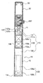
- FIG. 3 is a cross-sectional view showing the inside of FIG.
- FIG. 4 is a cross-sectional view showing a separate process of FIG.
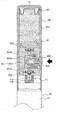
- Figure 5 is a partial cross-sectional view showing a state in which the beauty raw material is supplied by the present invention.
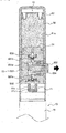
- FIG. 6 is a view showing a state after the operation of FIG.
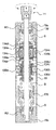
- FIG. 7 is a cross-sectional view showing the configuration of a vibration means according to another embodiment of the present invention.
- the present invention includes a massage means 10, a lid 30 and a cosmetic raw material supply means 50.
- the massage means 10 comprises, for example, a massage member 11, a vibration means 13, and a body 15.
- the massage member 11 is intended to vibrate and massage the skin in contact with the skin as shown on the right side of FIG. 4.
- the massage member 11 includes an insertion part 11a, a massage part 11b, and a receiving part 11c. do.
- Insertion portion (11a) is formed in a groove shape to be detachably coupled to the vibration member 131 of the vibration means 13 to be described later.
- the massage part 11b is a member extending in the opposite direction of the insertion part 11a to be in contact with the skin, and is preferably made of a soft synthetic resin material so as to gently massage the skin in contact with the skin.
- the user wears the massage member 11 for a long time, the user separates the massage member 11 from the vibration member 131 of the vibration means 13 and then attaches a new massage member 11 to the vibration means 13. Can be used in combination.
- the accommodating part 11c is formed in the end of the massage part 11b, and is comprised in the shape of the groove
- the massage member 11 may be formed to the protrusion 111 at the end to stimulate the skin as shown in enlarged in FIG.
- the vibration means 13 forms a magnetic field using the input power to vibrate the massage member 11, and includes, for example, a vibration member 131, a transformer 133, and a controller 135.
- the vibrating member 131 is detachably coupled to one end of the massage member 11, and the other end is rigid and shaft-shape to be fixed to the body 15 in a state where the permanent magnet 131a is integrally fixed. Is formed.
- the transformer 133 vibrates the vibrating member 131 by providing a magnetic field to the vibrating member 131.
- the transformer 133 includes a frequency oscillator 133a, a primary coil 133b, and a secondary coil 133c.
- the frequency oscillator 133a oscillates a constant frequency by using an input power source.
- the input power may be supplied by the power supply unit 138.
- a power supply unit 138 may be configured as a storage unit 138a for charging current and a charging unit 138b for charging a current supplied from the outside to the storage battery 138a.
- the power supply unit 138 may be composed of a power line or a battery for applying external power.
- the primary side coil 133b receives the oscillation voltage of the frequency oscillator 133a.
- the secondary side coil 133c amplifies the oscillation voltage input through the primary side coil 133b according to the set turns ratio and provides the amplified AC voltage to the permanent magnet 131a.
- the primary coil 133b and the secondary coil 133c are not installed outside the body 15 by the ferrite core 136 so that the magnetic field generated by being wrapped around the ferrite core 136 is discharged. .
- the controller 135 controls the transformer 133 by providing an input power to the transformer 133 so that the transformer 133 provides a magnetic field to the permanent magnet 131a to vibrate the vibration member 131.
- the control unit 135 is preferably connected to the switch 132 shown in FIG. 2 to apply the input power to the frequency oscillator 133a.
- the switch 132 is preferably installed in an exposed state outside the above-described body 15 so that the user can switch operation.
- the body 15 is formed in the shape of a housing such that the massage member 11 is installed at one end in a protruding state and the vibration means 13 is embedded therein. At this time, the other end of the body 15 may be opened, the vibration means 13 or other components may be embedded therein, and the other end may be closed by the stopper 134.
- the body 15 further includes fixing means 137 for vibratingly fixing the vibrating member 131 to the body 15.
- the fixing means 137 is configured to include, for example, the insertion portion 137a and the fixing ring 137b.
- Insertion portion 137a is formed in one end of the body 15, as shown in Figure 4 is configured in the groove shape so that the end of the vibration member 131 is inserted in a spaced apart state.
- the fixing ring 137b is made of a soft rubber material to be fixed to the inner surface of the insertion part 137a while being fitted to the vibration member 131. Accordingly, the fixing ring 137b may be smoothly fixed to vibrate while the vibrating member 131 does not contact the insertion part 137a.
- the lid 30 is detachably fixed to one end of the body 15 of the massage means 10 as shown in FIGS. 3 and 4, and is formed in a cap shape to cover and protect the massage member 11.
- the lid 30 may be formed in the air hole 31 so that the cosmetic material stored in the storage space (51a) to be described later is moved in the storage space (51a).
- the air hole 31 may be formed in the vertical direction or the side on the top of the lid 30.
- the air hole 31 may be provided with a breathable net (not shown) to prevent the inflow of foreign matter.
- Beauty raw material supply means 50 is built in the inside of the lid 30 to supply a certain amount of beauty raw material to the massage member 11 by an external pressure, for example, the sealing member 51, the plate 52, airless It comprises a pump 53 and a discharge member (55).
- the sealing member 51 is installed in the opening of the lid 30 so that the storage space 51a for storing the beauty raw material is formed in the lid 30, and the hollow is moved to move the beauty raw material stored in the storage space 51a. Is formed.
- Mild plate 52 is movable to the inside of the lid 30 is introduced into the storage space 51a through the air hole 31 formed through the lid 30 in accordance with the movement of the beauty material stored in the storage space 51a. Is moved by atmospheric pressure.
- the airless pump 53 is installed at one end of the sealing member 51 to pump cosmetic raw materials stored in the storage space 51a by external pressure.
- the fixed body 531 is inserted into the lid 30 to be fixed to one end of the sealing member 51, and the inlet is formed in both sides of the pumping chamber 531a and the pumping chamber 531a formed therein. 531b and the discharge port 531c.
- the suction valve 533 is provided at the inlet 531b side of the fixed body 531 to suck the cosmetic raw material stored in the storage space 51a into the pumping chamber 531a.
- the discharge valve 535 is provided at the discharge port 531c side of the fixed body 531 to discharge the cosmetic raw material sucked into the pumping chamber 531a to the discharge port 531c.
- the above-described suction valve 533 and discharge valve 535 is preferably composed of a check valve for moving the cosmetic raw material in one direction.
- the button 537 is elastically supported by the elastic body 534 embedded in the pumping chamber 531a and is installed in a fixed state 531 to be penetrated and pressed by external pressure to pump the cosmetic raw material stored in the storage space 51a.
- the button 537 When the button 537 is inserted into the pumping chamber 531a, the button 537 operates the discharge valve 535 to discharge the cosmetic raw material of the pumping chamber 531a to the discharge member 55 and protrudes from the pumping chamber 531a. In this case, by operating the suction valve 533 to inhale the cosmetic material in the storage space (51a) to the pumping chamber (531a). Therefore, the button 537 always pumps a certain amount of cosmetic raw materials.
- the discharge member 55 is hollow is formed so as to discharge the cosmetic raw material pumped by the airless pump (53).
- the discharge member 55 provides a predetermined amount of beauty raw material discharged by the pumping of the button 537 to the receiving portion 11c of the massage member 11 described above.
- the button 537 is inserted into the pumping chamber 531a while pressing the elastic body 534 to increase the internal pressure of the pumping chamber 531a.
- the discharge valve 535 discharges the cosmetic raw material pressurized in the pumping chamber 531a to the discharge member 55.
- the beauty raw material is accommodated in the receiving portion (11c) of the massage member (11).
- the button 537 lowers the internal pressure of the pumping chamber 531a while moving out of the pumping chamber 531a. Therefore, the suction valve 533 moves the cosmetic raw material of the storage space 51a to the pumping chamber 531a.
- the control of the control unit 135 as shown in the left side of FIG.
- the power supply unit 138 power is supplied to the frequency oscillator 133a.
- the frequency oscillator 133a oscillates a predetermined frequency by using the input power.
- the primary side coil 133b receives the oscillation voltage of the frequency oscillator 133a.
- the secondary side coil 133c amplifies the input oscillation voltage and provides the amplified AC voltage to the permanent magnet 131a.
- the permanent magnet 131a is vibrated while the attraction and repulsive force is generated by the magnetic field generated by the amplified AC voltage.
- the vibrating member 131 is vibrated about the fixing ring 137b together with the permanent magnet 131a vibrated by the magnetic field. Therefore, the massage member 11 stimulates the skin with vibration in a state coupled to the end of the vibration member 131.
- the present invention provides a massage in which the user massages the massage member 11 in contact with the skin after supplying the beauty raw material provided on the lid 30 to the massage member 11. You can massage your skin while stimulating it with vibration.
- the lid 30 is gripped by the body 15, the massage material 11 may be vibrated in a state in which beauty ingredients are not provided, and massage may be performed only by vibration.
- the user may use a massage member 11, which is formed at the end of the protrusion as shown in enlarged in FIG. 2 or alternatively, is attached to the vibration member 131 in the form of a brush.
- the massage member 11, the lid 30 and the cosmetic raw material supply means 50 of the massage means 10 is configured in the same configuration as described above, a detailed description thereof will be omitted.
- the vibrating means 13 is provided in the interior space of the body 15, the seal (15a, 15b) having the bearings (R1, R2) at both ends is provided with a driving force to the massage member (11) to massage To vibrate by rotating or rotating the member 11, for example, it comprises a shaft 132, a linear driving unit 134 and a rotary driving unit 136.
- the shaft 132 is embedded in the body 15 so as to linearly move and rotate in reciprocation.
- the shaft 132 is made of a non-magnetic material so as to prevent leakage, it is inserted into the seal (15a, 15b) and can be waterproof.
- the shaft 132 can be easily rotated and moved by the bearings (R1, R2).
- the linear driving unit 134 is for linearly moving the shaft 132 in a reciprocating manner, and includes, for example, a first mover and a first stator.
- the first mover has a first permanent magnet 134a fixed to the shaft 132 by being magnetized to have different polarities of both end faces in the axial direction of the shaft 132.
- the first permanent magnet (134a) is composed of a plurality of fitted to the shaft 132 is fixed by the spacer 134c fixed to both ends of the yoke (134d).
- the plurality of first permanent magnets 134a are fixed to the shaft 132 so that the polarities of the surfaces facing each other are the same. That is, when one side of the first permanent magnet 134a is S-pole and the other end is N-pole, the other side of the first permanent magnet 134a is N-pole and the other end is S-pole.
- the plurality of first permanent magnets 134a are arranged in the axial direction on one shaft 132, thereby generating a large magnetic flux.
- the first stator has a first coil 134b for generating a magnetic field by an alternating current input to the body 15 so as to face at intervals set in the first permanent magnet 134a.
- the first coil 134b is wound around the first bobbin 134e embedded in the body 15.
- the first coil 134b may move in one direction because the first permanent magnet 134a is moved in one direction. Therefore, when the alternating current is input, the first coil 134b may reciprocate the shaft 132 in a straight line.
- the linear driving unit 134 reciprocates the shaft 132
- the massage member 11 coupled to the shaft 132 has an effect of tapping the skin.
- the rotary drive unit 136 is for rotating the shaft 132 in a reciprocating manner, for example, comprises a second mover and a second stator.
- the second mover has at least one second permanent magnet 136a fixed to the shaft 132.
- the second permanent magnet 136a is formed in a flat shape and is fixed to the outside of the fixing member 136c fixed by being inserted into the shaft 132 by being configured in plurality.
- the second permanent magnet 136a is preferably configured to have a longer length than the second coil 136b to be described later.
- the second stator includes a second coil 136b which generates a magnetic field by an alternating current input to the body 15 while being wound around the shaft 132 so as to surround the second permanent magnet 136a.
- the second coil 136b is wound around the second bobbin 136c embedded in the body 15.
- the second coil 136b is provided with a plurality of yokes 136d.
- the second coil 136b may rotate the shaft 132 in one direction since one yoke 136d becomes an N pole and the other yoke 136d becomes an S pole.
- the second coil 136b may rotate the shaft 132 in the opposite direction. Accordingly, when the second coil 136b rotates the second permanent magnet 136a in a reciprocating manner when an alternating current is input, the shaft 132 may be rotated in reciprocation.
- the rotation driving unit 136 rotates the shaft 132 in a reciprocating manner, so that the massage member 11 coupled to the shaft 132 rubs the skin.
- the body 15 is spring (S) and the weight 138 is installed as shown.
- springs (S) elastically support the shaft 132 that is linearly moved or rotated.
- the weight 138 may be installed between the springs S to provide a reaction force to the shaft 132 that is linearly moved or rotated to reduce vibration of the shaft 132.
- the vibrating means 13 vibrates the shaft 132 by linearly moving or rotating the shaft 132, so that the user's skin can be variously stimulated and massaged.
Landscapes
- Health & Medical Sciences (AREA)
- Epidemiology (AREA)
- Pain & Pain Management (AREA)
- Physical Education & Sports Medicine (AREA)
- Rehabilitation Therapy (AREA)
- Life Sciences & Earth Sciences (AREA)
- Animal Behavior & Ethology (AREA)
- General Health & Medical Sciences (AREA)
- Public Health (AREA)
- Veterinary Medicine (AREA)
- Percussion Or Vibration Massage (AREA)
Abstract
Description
Claims (9)
- 피부에 접촉된 상태로 피부를 진동시켜서 마사지하는 마사지부재(11)와 입력되는 전원을 이용하여 자기장을 형성시켜서 상기 마사지부재(11)를 진동시키는 진동수단(13) 및 상기 마사지부재(11)가 일단에 돌출상태로 설치되고 진동수단(13)이 내장되는 몸체(15)를 포함하는 마사지수단(10);상기 마사지수단(10)의 몸체(15)의 일단에 탈착가능하게 고정되어 상기 마사지부재(11)를 커버하여 보호하는 뚜껑(30); 및상기 뚜껑(30)의 내측에 내장되어 외부압력에 의해 상기 마사지부재(11)에 일정량의 미용원료를 공급하는 미용원료공급수단(50);을 포함하는 마사지기.
- 제 1 항에 있어서, 상기 마사지부재(11)는,상기 진동수단(13)에 탈착가능하게 결합되도록 홈형태로 형성되는 삽입부(11a);상기 삽입부(11a)의 반대방향으로 연장형성되어 피부에 접촉되는 마사지부(11b); 및상기 마사지부(11b)의 단부에 형성되어 상기 미용원료공급수단(50)으로부터 공급되는 미용원료가 수용되는 홈형태의 수용부(11c);를 포함하는 마사지기.
- 제 1 항에 있어서, 상기 진동수단(13)은,상기 마사지부재(11)가 일단에 탈착가능하게 결합되고, 타단에 영구자석(131a)이 일체적으로 고정된 상태로 상기 몸체(15)에 진동가능하게 고정된 진동부재(131);상기 진동부재(131)에 자기장을 제공하여 진동부재(131)를 진동시키도록 일정한 주파수를 발진시키는 주파수발진기(133a)와 상기 주파수발진기(133a)의 발진전압을 입력받는 1차측코일(133b)과 상기 1차측코일(133b)을 통해 입력된 발진전압을 설정된 권선비에 따라 증폭시키고 증폭된 교류전압을 상기 영구자석(131a)으로 제공하는 2차측코일(133c)로 구성된 트랜스포머(133); 및상기 트랜스포머(133)가 상기 영구자석(131a)에 인력 및 척력을 제공하여 상기 마사지부재(11)가 진동되도록, 입력되는 전원을 상기 트랜스포머(133)에 제공하여 상기 트랜스포머(133)를 제어하는 제어부(135);를 포함하는 마사지기.
- 제 3 항에 있어서, 상기 진동부재(131)를 상기 몸체(15)에 진동가능하게 고정하는 고정수단(137);을 더 포함하며,상기 고정수단(137)은,상기 몸체(15)의 일단에 형성되어 상기 진동부재(131)의 단부가 이격상태로 삽입되는 홈형태의 삽입부(137a); 및상기 진동부재(131)에 끼워진 상태로 상기 삽입부(137a)의 내측면에 고정되는 연질의 고정링(137b);을 포함하는 마사지기.
- 제 1 항에 있어서, 상기 미용원료공급수단(50)은,상기 뚜껑(30)의 내부에 미용원료가 저장되는 저장공간(51a)이 형성되도록 뚜껑(30)의 개구부에 설치되고, 저장공간(51a)에 저장된 미용원료가 이동되는 중공의 밀폐부재(51);상기 뚜껑(30)의 내측에 이동가능하게 마련되어 상기 저장공간(51a)에 저장된 미용원료의 이동에 따라 저장공간(51a)으로 유입되는 대기압에 의해 이동되는 밀판(52);상기 밀폐부재(51)의 일단에 설치되면서 외압에 의해 저장공간(51a)에 저장된 미용원료를 펌핑하는 에어리스펌프(53); 및상기 에어리스펌프(53)에 의해 펌핑되는 미용원료를 배출하는 배출부재(55);를 포함하는 마사지기.
- 제 5 항에 있어서, 상기 에어리스펌프(53)는,상기 뚜껑(30)의 내측으로 삽입되어 상기 밀폐부재(51)의 일단에 고정되고, 내부에 형성되는 펌핑실(531a)과 펌핑실(531a)의 양측에 관통상태로 형성되는 유입구(531b) 및 토출구(531c)를 갖는 고정바디(531);상기 고정바디(531)의 유입구(531b)측에 마련되어 저장공간(51a)에 저장된 미용원료를 상기 펌핑실(531a)로 흡입시키는 흡입밸브(533);상기 고정바디(531)의 토출구(531c)측에 마련되어 상기 펌핑실(531a)로 흡입된 미용원료를 상기 토출구(531c)로 배출시키는 배출밸브(535); 및상기 펌핑실(531a)에 내장된 탄성체(534)에 탄력지지되면서 상기 고정바디(531)에 관통상태로 설치되어 외압에 의해 눌려지면서 상기 저장공간(51a)에 저장된 미용원료를 펌핌하는 버튼(537);을 포함하는 마사지기.
- 피부에 접촉된 상태로 피부를 진동시켜서 마사지하는 마사지부재(11)와 상기 마사지부재(11)에 구동력을 가하여 상기 마사지부재(11)를 직선이동시키거나 회전시켜서 진동시키는 진동수단(100) 및 상기 마사지부재(11)가 일단에 돌출상태로 설치되고 진동수단(13)이 내장되는 몸체(15)를 포함하는 마사지수단(10);상기 마사지수단(10)의 몸체(15)의 일단에 탈착가능하게 고정되어 상기 마사지부재(11)를 커버하여 보호하는 뚜껑(30); 및상기 뚜껑(30)의 내측에 내장되어 외부압력에 의해 상기 마사지부재(11)에 일정량의 미용원료를 공급하는 미용원료공급수단(50);을 포함하는 마사지기.
- 제 7 항에 있어서, 상기 진동수단(13)은,상기 몸체(15)에 왕복으로 직선이동 및 회전가능하게 내장된 샤프트(132);상기 샤프트(132)를 왕복으로 직선이동시키는 직선구동부(134); 및상기 샤프트(132)를 왕복으로 회전시키는 회전구동부(136);를 포함하는 마사지기.
- 제 8 항에 있어서, 상기 직선구동부(134)는,상기 샤프트(132)의 축방향에 양단면의 극성이 다르도록 착자되면서 샤프트(132)에 끼워져서 고정된 제1영구자석(134a)을 갖는 제1가동자; 및상기 제1영구자석(134a)에 설정된 간격으로 대향되게 상기 몸체(15)에 고정되어 입력되는 교류에 의해 자계를 발생시키는 제1코일(134b)을 갖는 제1고정자;상기 회전구동부(136)는,상기 샤프트(132)에 고정된 적어도 하나의 제2영구자석(136a)을 갖는 제2가동자; 및상기 제2영구자석(136a)을 둘러싸도록 상기 샤프트(132)의 주위에 감겨진 상태로 상기 몸체(15)에 고정되어 입력되는 교류에 의해 자계를 발생시키는 제2코일(136b)을 갖는 제2고정자;를 포함하는 마사지기.
Priority Applications (2)
| Application Number | Priority Date | Filing Date | Title |
|---|---|---|---|
| JP2014512771A JP5820527B2 (ja) | 2011-05-31 | 2012-05-29 | マッサージ器 |
| CN201290000518.XU CN203647679U (zh) | 2011-05-31 | 2012-05-29 | 按摩装置 |
Applications Claiming Priority (2)
| Application Number | Priority Date | Filing Date | Title |
|---|---|---|---|
| KR2020110004780U KR200462510Y1 (ko) | 2011-05-31 | 2011-05-31 | 마사지기 |
| KR20-2011-0004780 | 2011-05-31 |
Publications (2)
| Publication Number | Publication Date |
|---|---|
| WO2012165827A2 true WO2012165827A2 (ko) | 2012-12-06 |
| WO2012165827A3 WO2012165827A3 (ko) | 2013-04-04 |
Family
ID=47260053
Family Applications (1)
| Application Number | Title | Priority Date | Filing Date |
|---|---|---|---|
| PCT/KR2012/004196 Ceased WO2012165827A2 (ko) | 2011-05-31 | 2012-05-29 | 마사지기 |
Country Status (5)
| Country | Link |
|---|---|
| JP (1) | JP5820527B2 (ko) |
| KR (1) | KR200462510Y1 (ko) |
| CN (1) | CN203647679U (ko) |
| TW (1) | TWM442838U (ko) |
| WO (1) | WO2012165827A2 (ko) |
Cited By (2)
| Publication number | Priority date | Publication date | Assignee | Title |
|---|---|---|---|---|
| CN110575617A (zh) * | 2019-09-30 | 2019-12-17 | 广东顺德得品电子科技有限公司 | 一种美容仪 |
| CN111466698A (zh) * | 2020-05-18 | 2020-07-31 | 深圳憬然网络科技有限公司 | 护肤仪及其储液头和护肤方法 |
Families Citing this family (5)
| Publication number | Priority date | Publication date | Assignee | Title |
|---|---|---|---|---|
| KR200471796Y1 (ko) | 2013-01-02 | 2014-03-13 | (주)아모레퍼시픽 | 맛사지 겸용 에어리스 화장품 용기 |
| CN105976852B (zh) * | 2016-04-28 | 2018-07-31 | 上海斐讯数据通信技术有限公司 | 一种音乐播放器 |
| WO2020029071A1 (zh) * | 2018-08-07 | 2020-02-13 | 亦臻包装科技(苏州)有限公司 | 一种挤压式化妆品容器 |
| CN112385968A (zh) * | 2019-08-12 | 2021-02-23 | 徐逸奇 | 一种振动眼霜瓶 |
| CN113712370A (zh) * | 2021-08-11 | 2021-11-30 | 陈良婷 | 一种智能颈纹修复美容仪 |
Family Cites Families (9)
| Publication number | Priority date | Publication date | Assignee | Title |
|---|---|---|---|---|
| JPH0650641U (ja) * | 1992-12-22 | 1994-07-12 | 松下電工株式会社 | 手持ち式マッサージ機 |
| JPH08289911A (ja) * | 1995-04-21 | 1996-11-05 | Akira Nitta | 皮膚のマッサージ機 |
| JPH11332941A (ja) * | 1998-05-25 | 1999-12-07 | Mitsubishi Electric Corp | マッサージ装置 |
| JP4075001B2 (ja) * | 2003-06-17 | 2008-04-16 | ドクタース テック カンパニー リミティッド | 皮膚美容装置 |
| KR200348315Y1 (ko) * | 2004-02-05 | 2004-05-03 | 김승호 | 진동기능을 구비한 화장품 용기의 캡 |
| KR200427986Y1 (ko) | 2006-06-30 | 2006-10-04 | (주)아모레퍼시픽 | 피부 맛사지기 |
| JP2008264031A (ja) * | 2007-04-16 | 2008-11-06 | J Make:Kk | マッサージ器 |
| KR200450934Y1 (ko) | 2008-05-07 | 2010-11-18 | (주)아모레퍼시픽 | 마사지 부재가 구비된 펌프형 화장품 용기 |
| JP3165469U (ja) * | 2010-11-05 | 2011-01-20 | 珠海市庭佑化妝配件有限公司 | 振動按摩機能付き容器 |
-
2011
- 2011-05-31 KR KR2020110004780U patent/KR200462510Y1/ko not_active Expired - Fee Related
-
2012
- 2012-05-29 WO PCT/KR2012/004196 patent/WO2012165827A2/ko not_active Ceased
- 2012-05-29 TW TW101210219U patent/TWM442838U/zh not_active IP Right Cessation
- 2012-05-29 JP JP2014512771A patent/JP5820527B2/ja not_active Expired - Fee Related
- 2012-05-29 CN CN201290000518.XU patent/CN203647679U/zh not_active Expired - Fee Related
Cited By (2)
| Publication number | Priority date | Publication date | Assignee | Title |
|---|---|---|---|---|
| CN110575617A (zh) * | 2019-09-30 | 2019-12-17 | 广东顺德得品电子科技有限公司 | 一种美容仪 |
| CN111466698A (zh) * | 2020-05-18 | 2020-07-31 | 深圳憬然网络科技有限公司 | 护肤仪及其储液头和护肤方法 |
Also Published As
| Publication number | Publication date |
|---|---|
| CN203647679U (zh) | 2014-06-18 |
| WO2012165827A3 (ko) | 2013-04-04 |
| JP5820527B2 (ja) | 2015-11-24 |
| JP2014524764A (ja) | 2014-09-25 |
| KR200462510Y1 (ko) | 2012-09-13 |
| TWM442838U (en) | 2012-12-11 |
Similar Documents
| Publication | Publication Date | Title |
|---|---|---|
| WO2012165827A2 (ko) | 마사지기 | |
| CN110831562A (zh) | 用于压力波进行按摩的按摩装置 | |
| WO2013018968A1 (ko) | 세안장치 | |
| WO2010002135A2 (ko) | 피부 맛사지기 | |
| WO2013039303A2 (ko) | 상하운동 기능을 갖는 미용 장치 | |
| KR20110131338A (ko) | 진동 마스크 | |
| IL142290A (en) | Tremor for massage, for pain relief | |
| CN101365409A (zh) | 手持按摩工具 | |
| JP3145008U (ja) | 磁気健康器兼用の電動マッサージ器 | |
| WO2009093798A1 (en) | Container and scalp massager with the container | |
| CN201734921U (zh) | 迷你按摩器 | |
| KR20110128410A (ko) | 피부 미용기 | |
| CN218529252U (zh) | 一种悬浮式美容仪 | |
| JP3160611U (ja) | 電動マッサージ機 | |
| WO2010071257A1 (ko) | 휴대용 마사지기 | |
| CN209847034U (zh) | 一种洁面仪 | |
| KR200471802Y1 (ko) | 주름관을 결합한 진동형 화장용 튜브 | |
| WO2022244897A1 (ko) | 휴대용 복합 피부관리기 | |
| JP2013188250A (ja) | 振動ヘアブラシ | |
| KR101008674B1 (ko) | 컨테이너 및 그 컨테이너를 구비한 두피 마사지기 | |
| CN209475392U (zh) | 肌肤护理装置 | |
| CN210447847U (zh) | 电动物理渗透仪 | |
| CN215387048U (zh) | 美容仪 | |
| RU2012323C1 (ru) | Устройство для самомассажа | |
| CN111514007A (zh) | 一种腰腿疼治疗仪 |
Legal Events
| Date | Code | Title | Description |
|---|---|---|---|
| WWE | Wipo information: entry into national phase |
Ref document number: 201290000518.X Country of ref document: CN |
|
| 121 | Ep: the epo has been informed by wipo that ep was designated in this application |
Ref document number: 12792331 Country of ref document: EP Kind code of ref document: A2 |
|
| ENP | Entry into the national phase |
Ref document number: 2014512771 Country of ref document: JP Kind code of ref document: A |
|
| NENP | Non-entry into the national phase |
Ref country code: DE |
|
| 32PN | Ep: public notification in the ep bulletin as address of the adressee cannot be established |
Free format text: NOTING OF LOSS OF RIGHTS PURSUANT TO RULE 112(1) EPC (EPO FORM 1205 DATED 02.04.2014) |
|
| 122 | Ep: pct application non-entry in european phase |
Ref document number: 12792331 Country of ref document: EP Kind code of ref document: A2 |