WO2012165742A1 - Dispositif d'injection de combustible rotatif pour statoréacteur et statoréacteur équipé de ce dispositif - Google Patents
Dispositif d'injection de combustible rotatif pour statoréacteur et statoréacteur équipé de ce dispositif Download PDFInfo
- Publication number
- WO2012165742A1 WO2012165742A1 PCT/KR2011/010339 KR2011010339W WO2012165742A1 WO 2012165742 A1 WO2012165742 A1 WO 2012165742A1 KR 2011010339 W KR2011010339 W KR 2011010339W WO 2012165742 A1 WO2012165742 A1 WO 2012165742A1
- Authority
- WO
- WIPO (PCT)
- Prior art keywords
- fuel
- fuel injection
- ramjet engine
- housing
- injection device
- Prior art date
Links
Images
Classifications
-
- F—MECHANICAL ENGINEERING; LIGHTING; HEATING; WEAPONS; BLASTING
- F02—COMBUSTION ENGINES; HOT-GAS OR COMBUSTION-PRODUCT ENGINE PLANTS
- F02K—JET-PROPULSION PLANTS
- F02K7/00—Plants in which the working fluid is used in a jet only, i.e. the plants not having a turbine or other engine driving a compressor or a ducted fan; Control thereof
- F02K7/10—Plants in which the working fluid is used in a jet only, i.e. the plants not having a turbine or other engine driving a compressor or a ducted fan; Control thereof characterised by having ram-action compression, i.e. aero-thermo-dynamic-ducts or ram-jet engines
- F02K7/16—Composite ram-jet/turbo-jet engines
-
- F—MECHANICAL ENGINEERING; LIGHTING; HEATING; WEAPONS; BLASTING
- F02—COMBUSTION ENGINES; HOT-GAS OR COMBUSTION-PRODUCT ENGINE PLANTS
- F02K—JET-PROPULSION PLANTS
- F02K7/00—Plants in which the working fluid is used in a jet only, i.e. the plants not having a turbine or other engine driving a compressor or a ducted fan; Control thereof
- F02K7/10—Plants in which the working fluid is used in a jet only, i.e. the plants not having a turbine or other engine driving a compressor or a ducted fan; Control thereof characterised by having ram-action compression, i.e. aero-thermo-dynamic-ducts or ram-jet engines
-
- F—MECHANICAL ENGINEERING; LIGHTING; HEATING; WEAPONS; BLASTING
- F02—COMBUSTION ENGINES; HOT-GAS OR COMBUSTION-PRODUCT ENGINE PLANTS
- F02C—GAS-TURBINE PLANTS; AIR INTAKES FOR JET-PROPULSION PLANTS; CONTROLLING FUEL SUPPLY IN AIR-BREATHING JET-PROPULSION PLANTS
- F02C7/00—Features, components parts, details or accessories, not provided for in, or of interest apart form groups F02C1/00 - F02C6/00; Air intakes for jet-propulsion plants
- F02C7/22—Fuel supply systems
Definitions
- the present invention relates to a fuel injection device and an engine, and more particularly, to a rotary fuel injection device for a ram jet engine and a ram jet engine.
- the air sucked between the case and the diffuser of the ramjet engine inlet is compressed and mixed with fuel injected from a fixed number of fixed fuel nozzles.
- the fuel air mixer is burned near the flame stabilizer in the combustor, and hot gas generated at this time is ejected through the nozzle to obtain propulsion force.
- Embodiments of the present invention drive a turbine using a high pressure air of the ramjet engine, a rotation type for a ramjet engine that can inject the atomized fuel particles uniformly by injecting fuel by rotating the fuel injection unit at a high speed with the drive force of the turbine To provide a fuel injection device and a ramjet engine.
- the housing is disposed in the flow path through which the air flows, the housing has an air flow path for the air flows in and out; And a fuel supply unit connected to the housing to supply fuel to the inside of the housing, and a fuel injection unit connected to the turbine to rotate and inject the fuel supplied from the fuel supply unit to the outside.
- Rotary fuel injection may be provided.
- the air flow passage may further include an air flow rate control valve for controlling the air flow of the air flow path.
- the air flow rate control valve may be installed in a portion where the air of the air flow path is discharged.
- the housing may be in the form of a truncated cone.
- the apparatus may further include a rotation shaft disposed between the turbine and the fuel injection unit to connect the turbine and the fuel injection unit.
- the apparatus may further include a bearing disposed between the rotation shaft and the housing.
- the fuel supply part may include a support duct connected to the housing while forming an exterior, a fuel supply pipe inserted into the support duct and connected to a ramjet engine case to supply fuel from the outside, and part of the fuel injection part. It is installed to be inserted, and may be provided with a fuel supply stage for injecting the fuel supplied from the fuel supply pipe into the fuel injection unit.
- the fuel supply stand may include a first orifice formed on an outer surface of the fuel supply stand.
- the first orifice may include a plurality of first orifices, and the plurality of first orifices may be formed to be spaced apart from each other by a predetermined distance on an outer surface of the fuel supply table.
- the fuel injection part may include a second orifice formed on an outer surface of the fuel injection part to inject the fuel supplied from the fuel supply part to the outside.
- the second orifice may include a plurality of second orifices, and the plurality of second orifices may be formed to be spaced apart from each other by a predetermined interval on the outer surface of the fuel injection unit.
- the second orifice may be formed to have a predetermined angle with the outer surface of the fuel injection portion.
- the second orifice may be formed to have one of an acute angle, a right angle, or an obtuse angle from the horizontal center line of the housing.
- the housing may include a main body in which the air flow path is formed, the main body in which the turbine is disposed, and a protective housing disposed on one side of the fuel injection part so as to be separated from the main body and surrounding a part of the fuel supply part. It can be provided.
- Another aspect of the present invention can provide a ramjet engine including a rotary fuel injection device for a ramjet engine.
- it may further include a case disposed to surround the outer surface of the rotary jet fuel injection device for the ramjet engine flows outside air.
- the case may be formed to protrude inside the case may include a nozzle unit for adjusting the pressure and speed of the combustion gas discharged from the case.
- the ignition unit may further include an ignition unit disposed at a rear surface of the rotatable fuel injection device for the ramjet engine to ignite a mixed gas mixed with fuel and external air injected from the rotatable fuel injection device for the ramjet engine.
- the apparatus may further include a flame stabilizer disposed at a rear surface of the fuel injection device for the ram jet engine and installed at a portion where combustion of the mixed gas in which fuel and external air are injected from the rotary fuel injection device for the ram jet engine occurs. Can be.
- Embodiments of the present invention can improve the performance of the ramjet engine by uniformly atomizing the fuel particles.
- embodiments of the present invention can increase the efficiency of the ramjet engine by using a portion of the internal air is unnecessary the use of a high-pressure fuel pump.
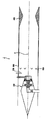
- FIG. 1 is a conceptual diagram illustrating a ramjet engine according to an embodiment of the present invention.
- FIG. 2 is a conceptual view illustrating a rotary fuel injection device for a ramjet engine according to another embodiment of the present invention.
- FIG. 3 is an operation diagram showing an operating state of the ramjet engine shown in FIG.
- FIG. 4 is an operation diagram showing an operating state of the rotary fuel injection device for a ramjet engine shown in FIG.
- Ramjet engine (J) may include a ramjet engine (not shown) and a scramjet engine (not shown).
- a ramjet engine (not shown)
- a scramjet engine (not shown)
- the ramjet engine J will be described below with reference to the ramjet engine for convenience of description.
- FIG. 1 is a conceptual view illustrating a ramjet engine J according to an embodiment of the present invention.
- the ramjet engine J includes a case 200 forming an appearance.
- the case 200 may have a space formed therein to allow external air to flow therein.
- the ramjet engine J includes a rotary fuel injection device 100 for a ramjet engine disposed inside the case.
- the rotary fuel injection device 100 for a ramjet engine may be formed to radially inject fuel.
- the ramjet engine (J) may include an ignition unit 300 which is disposed on the rear of the rotary fuel injection device 100 for ramjet engine. At this time, the ignition unit 300 may supply energy to the mixed gas to ignite the mixed gas mixed with the outside air and fuel.
- Ramjet engine (J) may include a flame stabilizer (500) disposed on the rear of the rotary fuel injection device 100 for ramjet engine.
- Flame ballast 500 may be installed in the portion where the combustion of the mixed gas occurs.
- the flame ballast 500 may be installed in the case 200 at least one portion is formed to be bent.
- the ramjet engine (J) may include a nozzle unit 400 is formed to protrude inside the case 200. At this time, the nozzle unit 400 may adjust the pressure and speed of the combustion gas discharged from the case 200.
- the nozzle unit 400 may be formed to protrude into the case 200 to vary the inner width of the case 200.
- the nozzle unit 400 may be formed differently according to the output of the ramjet engine (J).
- the combustion gas may vary in pressure and speed while passing through the nozzle unit 400. For example, while the combustion gas passes through the nozzle unit 400, the positive pressure may decrease and the speed may increase.
- the combustion gas may be discharged to the outside through the nozzle unit 400 at high speed, thereby improving propulsion of the vehicle.
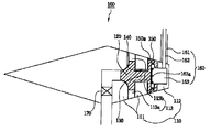
- FIG. 2 is a conceptual view illustrating a rotatable fuel injection device 100 for a ramjet engine according to another embodiment of the present invention.
- the rotary fuel injection device 100 for a ramjet engine includes a housing 110 disposed inside the case 200.
- the housing 110 may be formed in various forms.
- the housing 110 may be formed in a pentagonal shape.
- the housing 110 may be formed in the shape of a truncated cone.
- the housing 110 may include an air flow path 113 to be described later, and a main body 111 in which a turbine 120 to be described later is disposed.
- the body 111 may be formed in various forms as described above.
- the housing 110 may include a protective housing 112 disposed at one side of the fuel injection unit 150 to be described later.
- the protective housing 112 is located in a straight line with the main body 111, but may be disposed separately from the main body ().
- the inside of the protective housing 112 may be disposed so that a part of the fuel supply unit 160 to be described later is inserted.
- the protective housing 112 may protect the fuel supply pipe 162 and the fuel supply stand 163 from the high heat generated during combustion by inserting a portion of the fuel supply pipe 162 and the fuel supply stand 163 to be described later. .
- the housing 110 may include an air flow path 113 for guiding external air so that external air flowing through the case 200 flows in and flows out.
- the air flow path 113 may be formed to be bent inside the housing 110.
- the air flow path 113 may flow in and discharge external air flowing between the housing 110 and the case 200.
- the rotary fuel injection device 100 for a ramjet engine may include an air flow control valve 170 disposed in the air flow passage 113. At this time, the air flow rate control valve 170 may control the amount of air flowing through the air flow path (113).
- the air flow control valve 170 may be disposed at various positions.
- the air flow control valve 170 may be installed in a portion of the air discharged air passage 113. Therefore, the air flow rate control valve 170 may control the rotational speed of the turbine 120 to be described later by controlling the amount of air flowing.
- the rotary fuel injection device 100 for a ramjet engine includes a turbine 120 disposed in the air flow path (113).
- the turbine 120 may rotate by air when air flows through the air flow passage 113.
- the rotary fuel injection device 100 for a ramjet engine includes a fuel supply unit 160 connected to the housing 110 to supply fuel into the housing 110.
- the fuel supply unit 160 may include a support duct 161 inserted into the case 200 and connected to the protective housing 112.
- the fuel supply unit 160 may include a fuel supply pipe 162 disposed inside the support duct 161 and connected to be inserted into the protective housing 112.
- the fuel supply unit 160 may include a fuel supply unit 163 installed to be partially inserted into the fuel injection unit 150. In this case, the fuel supply stand 163 may inject the fuel supplied from the fuel supply pipe 162 into the fuel injection unit 150.
- the fuel supply base 163 may be formed in a cylindrical shape.
- the fuel supply base 163 may include a first orifice 163a formed on an outer surface of the cylinder.
- a plurality of first orifices 163a may be formed.
- the plurality of first orifices 163a may be formed to be spaced apart from each other by a predetermined interval on the outer surface of the fuel supply base 163.
- the rotary fuel injection device 100 for a ramjet engine includes a fuel injection unit 150 which is connected to the turbine 120 and rotates.
- the fuel injection unit 150 may have a space formed therein to temporarily store fuel supplied from the fuel supply unit 160.
- the fuel injection unit 150 may include a second orifice 150a formed on an outer surface of the fuel injection unit 150 to inject the fuel supplied from the fuel supply unit 160 to the outside.
- the second orifice 150a may eject the fuel supplied into the fuel injection unit 150 to the outside.
- the second orifice 150a may be formed to have a predetermined angle with the outer surface of the fuel injection unit 150.
- the second orifice 150a may form one of an acute angle, a right angle, or an obtuse angle from the horizontal center line C of the housing 110.
- a plurality of second orifices 150a may be formed similarly to the first orifice 163a.
- the plurality of second orifices 150a may be formed on the outer surface of the fuel injection unit 150 by being spaced apart from each other by a predetermined interval.
- the rotary fuel injection device 100 for a ramjet engine may include a rotation shaft 130 disposed between the turbine 120 and the fuel injection unit 150.
- the rotation shaft 130 may connect the turbine 120 and the fuel injection unit 150 to transmit the rotation of the turbine 120 to the fuel injection unit 150.
- the rotary fuel injection device 100 for a ramjet engine may include a bearing 140 disposed between the rotation shaft 130 and the housing 110.
- the bearing 140 may reduce friction between the housing 110 and the rotating shaft 130 while rotating.
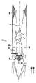
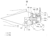
- FIG. 3 is an operation diagram showing an operating state of the ramjet engine (J) shown in FIG. 4 is an operation diagram showing an operating state of the rotary fuel injection device 100 for a ramjet engine shown in FIG.
- the compressed air between the case 200 and the rotary fuel injection device 100 for the ramjet engine may be discharged to one side of the case 200 by being mixed with the fuel and combusted.
- the turbine 120 is directly connected to the air inlet 113a of the air flow path 113, as described above, the air inlet 113a is a high pressure formed by the ramjet engine type fuel injection device 100 It serves as an inlet for directing air into the turbine 120.
- the high pressure air guided by the air intake 113a rotates the turbine 120 at a speed of 0 to 100,000 rpm.
- the turbine 120 may be rotated from 0 to 100,000 rpm and may operate in a condition that the inlet pressure is about 2 to 5 times higher than the outlet pressure.
- the air flow path 113 connected to the turbine 120 serves to discharge the air to the air outlet (113b), the air flow control valve 170 has a function to control the discharged air flow turbine 120 To adjust the number of revolutions.
- the turbine 120 and the fuel injection unit 150 are directly connected to the rotating shaft 130, the rotating shaft 130 is in contact with the plurality of bearings 140, and the bearing 140 is supported by the housing 110.
- the air compressed in the case 200 and the rotary fuel injection device 100 for the ram jet engine is opened via the air inlet 113a of the air flow path 113 when the air flow control valve 170 is opened. 120 is driven, the air driving the turbine 120 is discharged to the outside of the ram jet engine (J) from the air outlet 113b of the air flow path 113 along the air flow path (113).
- the rotating shaft 130 When the turbine 120 starts to operate, the rotating shaft 130 also rotates at the same speed as the turbine 120, wherein the rotating shaft 130 is contacted by the bearing 140 and the bearing 140 is connected to the housing 110. Is supported by.
- the fuel supply unit 163 is slightly separated from the fuel injection unit 150, and a plurality of first orifices 163a are installed at the ends of the fuel supply unit 163, thereby discharging fuel and rotating at high speed.
- the fuel is supplied to the inner surface of the fuel injection unit 150.
- the plurality of first orifices 163a serve to supply a predetermined amount of fuel transferred through the fuel supply pipe 162 to the inner surface of the fuel injection unit 150 through the fuel supply base 163.
- the fuel supplied to the inner surface of the fuel injection unit 150 injects the atomized liquid uniformly in an annular shape through the plurality of second orifices 150a by the centrifugal force of the fuel injection unit 150.
- the fuel uniformly sprayed in an annular shape is mixed with the air flowing through the case 200 and the rotary fuel injection device 100 for the ramjet engine, and the fuel is introduced into the case 200.
- the protective housing 112 for protecting the fuel nozzle from the high temperature combustion temperature is located in the right direction of the fuel injection unit 150, the support duct 161 for supporting the protective housing 112 is the case ( 200) It is attached to the wall.
- the igniter 300 is made of an igniter to form a flame in the case 200 and then discharged to the outside through the nozzle unit 400. Therefore, the ramjet engine (J) can implement a stable and high efficiency output through the above process.
- the rotary fuel injection device 100 for a ramjet engine rotates the turbine 120 by using high pressure air therein, and rotates the fuel injection unit 150 directly connected to the rotary shaft 130 by using the centrifugal force generated at this time.
- the fuel injection unit 150 Through the second orifice 150a installed in the fuel injection unit 150, the fuel is uniformly injected to all the regions.
- the ramjet engine (J) can make the fuel injection uniformly in the circumferential direction through the rotary fuel injection device (100) for the ramjet engine, and finely and uniformly use the fuel by the centrifugal force of the fuel injection unit (150). Spraying has the advantage of not needing a high pressure fuel pump.
- the ramjet engine (J) is well mixed with the air due to the uniform fuel distribution, it is possible to greatly improve the combustion performance and combustion stability.
- the present invention relates to a rotary fuel injection device for a ramjet engine and a ramjet engine. Therefore, the present invention can be used in various industrial fields such as the automobile field, the aircraft field, and the ship field that require a jet engine.
Landscapes
- Engineering & Computer Science (AREA)
- Chemical & Material Sciences (AREA)
- Combustion & Propulsion (AREA)
- Mechanical Engineering (AREA)
- General Engineering & Computer Science (AREA)
- Fuel-Injection Apparatus (AREA)
- Nozzles (AREA)
Abstract
La présente invention porte sur un dispositif d'injection de combustible pour un statoréacteur et sur un statoréacteur équipé de ce dispositif. La présente invention comprend : un corps présentant une voie de passage d'air qui est formée sur un trajet d'écoulement dans lequel l'air circule de telle sorte que l'air est introduit et rejeté à l'extérieur ; une turbine qui est montée à l'intérieur du corps et qui est entraînée en rotation au moyen de l'air qui passe dans la voie de passage d'air ; une partie d'alimentation en carburant qui est reliée au corps, et qui sert à amener le carburant à l'intérieur du corps ; et une partie d'injection du carburant qui tourne avec la turbine pour injecter le carburant qui est amené en provenance de la partie d'amenée de carburant vers l'extérieur. La présente invention comprend aussi le dispositif d'injection de carburant rotatif utilisé pour le statoréacteur.
Applications Claiming Priority (2)
| Application Number | Priority Date | Filing Date | Title |
|---|---|---|---|
| KR1020110053101A KR101251410B1 (ko) | 2011-06-02 | 2011-06-02 | 램제트엔진용 회전형 연료분사장치 및 이를 구비한 램제트엔진 |
| KR10-2011-0053101 | 2011-06-02 |
Publications (1)
| Publication Number | Publication Date |
|---|---|
| WO2012165742A1 true WO2012165742A1 (fr) | 2012-12-06 |
Family
ID=47259559
Family Applications (1)
| Application Number | Title | Priority Date | Filing Date |
|---|---|---|---|
| PCT/KR2011/010339 WO2012165742A1 (fr) | 2011-06-02 | 2011-12-29 | Dispositif d'injection de combustible rotatif pour statoréacteur et statoréacteur équipé de ce dispositif |
Country Status (2)
| Country | Link |
|---|---|
| KR (1) | KR101251410B1 (fr) |
| WO (1) | WO2012165742A1 (fr) |
Cited By (1)
| Publication number | Priority date | Publication date | Assignee | Title |
|---|---|---|---|---|
| CN110617159A (zh) * | 2019-09-18 | 2019-12-27 | 中南大学 | 一种振动筛式供粉装置及其粉末冲压发动机 |
Families Citing this family (3)
| Publication number | Priority date | Publication date | Assignee | Title |
|---|---|---|---|---|
| KR102298621B1 (ko) | 2020-02-12 | 2021-09-06 | 현대로템 주식회사 | 덕티드 램제트 엔진용 가스유량 조절기 |
| KR102325902B1 (ko) | 2020-02-21 | 2021-11-12 | 현대로템 주식회사 | 덕티드 램제트 엔진용 회전형 가스유량 조절기 |
| KR102471814B1 (ko) | 2020-12-29 | 2022-11-29 | 현대로템 주식회사 | 덕티드 램제트 엔진용 가스유량 조절기 |
Citations (5)
| Publication number | Priority date | Publication date | Assignee | Title |
|---|---|---|---|---|
| JPH1047161A (ja) * | 1996-07-30 | 1998-02-17 | Ishikawajima Harima Heavy Ind Co Ltd | エアターボラムジェットエンジン |
| JPH11336566A (ja) * | 1998-05-26 | 1999-12-07 | Ishikawajima Harima Heavy Ind Co Ltd | 超音速機用推進機関の燃料供給装置 |
| US6263660B1 (en) * | 1998-08-17 | 2001-07-24 | Ramgen Power Systems, Inc. | Apparatus and method for fuel-air mixing before supply of low pressure lean pre-mix to combustor for rotating ramjet engine driving a shaft |
| KR100521393B1 (ko) * | 2001-07-18 | 2005-10-14 | 이재창 | 방출배기를 이용한 분사추진기관 |
| US20060042227A1 (en) * | 2004-08-27 | 2006-03-02 | Coffinberry George A | Air turbine powered accessory |
Family Cites Families (2)
| Publication number | Priority date | Publication date | Assignee | Title |
|---|---|---|---|---|
| JPH0849852A (ja) * | 1994-08-02 | 1996-02-20 | Mitsubishi Heavy Ind Ltd | 遠心式燃料噴霧装置 |
| JP3743459B2 (ja) * | 1995-10-27 | 2006-02-08 | 石川島播磨重工業株式会社 | ラム燃焼器 |
-
2011
- 2011-06-02 KR KR1020110053101A patent/KR101251410B1/ko active IP Right Grant
- 2011-12-29 WO PCT/KR2011/010339 patent/WO2012165742A1/fr active Application Filing
Patent Citations (5)
| Publication number | Priority date | Publication date | Assignee | Title |
|---|---|---|---|---|
| JPH1047161A (ja) * | 1996-07-30 | 1998-02-17 | Ishikawajima Harima Heavy Ind Co Ltd | エアターボラムジェットエンジン |
| JPH11336566A (ja) * | 1998-05-26 | 1999-12-07 | Ishikawajima Harima Heavy Ind Co Ltd | 超音速機用推進機関の燃料供給装置 |
| US6263660B1 (en) * | 1998-08-17 | 2001-07-24 | Ramgen Power Systems, Inc. | Apparatus and method for fuel-air mixing before supply of low pressure lean pre-mix to combustor for rotating ramjet engine driving a shaft |
| KR100521393B1 (ko) * | 2001-07-18 | 2005-10-14 | 이재창 | 방출배기를 이용한 분사추진기관 |
| US20060042227A1 (en) * | 2004-08-27 | 2006-03-02 | Coffinberry George A | Air turbine powered accessory |
Cited By (1)
| Publication number | Priority date | Publication date | Assignee | Title |
|---|---|---|---|---|
| CN110617159A (zh) * | 2019-09-18 | 2019-12-27 | 中南大学 | 一种振动筛式供粉装置及其粉末冲压发动机 |
Also Published As
| Publication number | Publication date |
|---|---|
| KR20120134297A (ko) | 2012-12-12 |
| KR101251410B1 (ko) | 2013-04-05 |
Similar Documents
| Publication | Publication Date | Title |
|---|---|---|
| US4891936A (en) | Turbine combustor with tangential fuel injection and bender jets | |
| US6178751B1 (en) | Liquid fuel injector system | |
| US4222243A (en) | Fuel burners for gas turbine engines | |
| WO2012165742A1 (fr) | Dispositif d'injection de combustible rotatif pour statoréacteur et statoréacteur équipé de ce dispositif | |
| WO2013180424A1 (fr) | Appareil de prémélange carburant-air utilisant un dispositif d'injection rotatif et brûleur de turbine à gaz le comprenant | |
| CN103822228B (zh) | 燃料喷嘴及其组装方法 | |
| EP0348500A1 (fr) | Unite de combustion annulaire avec injection d'air de refroidissement tangentiel. | |
| GB780493A (en) | Improvements relating to combustion equipment for gas-turbine engines | |
| CN103266922B (zh) | 一种带有级间燃烧室的涡轮静子叶片 | |
| CN108613217B (zh) | 一种分配式部分预混喷注装置及燃烧室 | |
| WO2017175918A1 (fr) | Dispositif de combustion à émission ultra-faible | |
| WO2017175958A1 (fr) | Dispositif de combustion industriel | |
| JP2012037225A (ja) | タービンエンジン用の燃焼器アセンブリ及びその組み立て方法 | |
| WO2021025524A1 (fr) | Turbine à action et dispositif de turbine | |
| CN105593602B (zh) | 通过燃料喷射系统均匀进气的涡轮发动机的燃烧室 | |
| WO2014148804A1 (fr) | Torche à plasma | |
| WO2016093430A1 (fr) | Ensemble appareil de tourbillonnement | |
| US4085585A (en) | Impaction/induction jet engine | |
| KR100858964B1 (ko) | 토치를 응용한 소형 제트엔진 후기 연소기 | |
| WO2020050689A1 (fr) | Dispositif de propulsion pour moteur-fusée à propergol liquide | |
| JPS5824695B2 (ja) | ガスタ−ビンエンジンの燃焼器構造 | |
| JP3712505B2 (ja) | ガス焚き予混合燃焼装置 | |
| GB811745A (en) | Improvements relating to combustion chambers for gas-turbine or jet-propulsion devices and the method of operating the same | |
| KR20060132297A (ko) | 가스터빈엔진 | |
| KR820001469B1 (ko) | 가스터빈 엔진용 연소장치 |
Legal Events
| Date | Code | Title | Description |
|---|---|---|---|
| 121 | Ep: the epo has been informed by wipo that ep was designated in this application |
Ref document number: 11866591 Country of ref document: EP Kind code of ref document: A1 |
|
| NENP | Non-entry into the national phase |
Ref country code: DE |
|
| 122 | Ep: pct application non-entry in european phase |
Ref document number: 11866591 Country of ref document: EP Kind code of ref document: A1 |