WO2012165391A1 - コネクタ - Google Patents
コネクタ Download PDFInfo
- Publication number
- WO2012165391A1 WO2012165391A1 PCT/JP2012/063671 JP2012063671W WO2012165391A1 WO 2012165391 A1 WO2012165391 A1 WO 2012165391A1 JP 2012063671 W JP2012063671 W JP 2012063671W WO 2012165391 A1 WO2012165391 A1 WO 2012165391A1
- Authority
- WO
- WIPO (PCT)
- Prior art keywords
- connector
- male
- female
- liquid
- valve body
- Prior art date
- Legal status (The legal status is an assumption and is not a legal conclusion. Google has not performed a legal analysis and makes no representation as to the accuracy of the status listed.)
- Ceased
Links
Images




Classifications
-
- F—MECHANICAL ENGINEERING; LIGHTING; HEATING; WEAPONS; BLASTING
- F16—ENGINEERING ELEMENTS AND UNITS; GENERAL MEASURES FOR PRODUCING AND MAINTAINING EFFECTIVE FUNCTIONING OF MACHINES OR INSTALLATIONS; THERMAL INSULATION IN GENERAL
- F16L—PIPES; JOINTS OR FITTINGS FOR PIPES; SUPPORTS FOR PIPES, CABLES OR PROTECTIVE TUBING; MEANS FOR THERMAL INSULATION IN GENERAL
- F16L37/00—Couplings of the quick-acting type
- F16L37/28—Couplings of the quick-acting type with fluid cut-off means
- F16L37/30—Couplings of the quick-acting type with fluid cut-off means with fluid cut-off means in each of two pipe-end fittings
- F16L37/32—Couplings of the quick-acting type with fluid cut-off means with fluid cut-off means in each of two pipe-end fittings at least one of two lift valves being opened automatically when the coupling is applied
- F16L37/34—Couplings of the quick-acting type with fluid cut-off means with fluid cut-off means in each of two pipe-end fittings at least one of two lift valves being opened automatically when the coupling is applied at least one of the lift valves being of the sleeve type, i.e. a sleeve being telescoped over an inner cylindrical wall
Definitions
- This invention relates to a connector for connecting a plurality of flow paths through which a liquid flows.
- Some connectors for connecting a plurality of flow paths include a female connector and a male connector each having a valve mechanism inside (see, for example, Patent Document 1).
- the male-side valve mechanism is brought into contact with the connection surface of the male connector and the connection surface of the female connector, and the male connector is inserted into the female connector. Then, the valve mechanism on the female side is opened, and one flow path connected to the male connector is connected to the other flow path connected to the female connector.
- the present invention has been made in view of the above problems, and an object of the present invention is to provide a connector capable of preventing liquid from adhering to a connection surface when a flow path is disconnected.
- the present invention provides a male connector having a male case having a flow path through which liquid flows, a male valve mechanism provided in the male case, and a flow path through which liquid flows.
- a female connector having a female-side case and a female-side valve mechanism provided in the female-side case, and the male-side valve when the male connector and the female-type connector are disconnected.
- a connection surface provided in the male connector and connected to the female connector, and a connection surface provided in the female connector and connected to the male connector At least one of the connectors is provided with an absorber that absorbs the liquid.
- the male connector and the female connector can be disconnected when the male connector and the female connector are disconnected.
- a small amount of liquid that has entered the gap between the mold connector and the female connector can be absorbed by the absorber. For this reason, when connection is cancelled
- the male side valve mechanism and the female side valve mechanism include a valve body that abuts on the connection surface facing when the male connector and the female connector are coupled, and the valve body. It is preferable that each of the valve bodies is provided with an urging portion that urges the flow path to a closed position where the flow path is not communicated.
- the absorber since the absorber is provided in at least one of the valve bodies, when the female connector and the male connector are connected, the absorber faces the valve body and the valve body. It will be in the state pinched
- the male connector and the female connector each have a connection surface that comes into contact with each valve body provided in the male side valve mechanism and the female side valve mechanism when they are connected to each other. And it is preferable that the said absorber is provided in at least one of each connection surface contact
- the absorber is provided on at least one of the connection surfaces in contact with the valve body, when the female connector and the male connector are connected, the absorber is the valve body. And the connection surface. Therefore, since the absorber is pressed between the valve body and the connection surface by the urging force of the urging portion, the amount of liquid that can be absorbed by the absorber in that state is the amount of liquid that can be absorbed by the absorber when not pressed. Less than the amount. Therefore, when the connection between the female connector and the male connector is released, the absorber has a room for absorbing the liquid, and the liquid that has entered the connection surface can be easily absorbed.
- the absorber is made of a stretchable material.
- the state is compressed between the connection surfaces, and when the connection is released, the compressed state returns to the original state. And in the state where the absorber was compressed, the amount of liquid absorption is less than in the uncompressed state. For this reason, when the connection between the female connector and the male connector is released, the absorber has a room for absorbing the liquid, and can absorb the liquid that has entered the connection surface.
- the absorber covers a connection surface exposed to the outside of the male connector or the female connector that has been disconnected.
- the absorber is provided so as to cover the connection surface exposed to the outside. That is, in the state where the absorber is not provided, there is a possibility that the liquid may adhere to the periphery of the connector when the liquid adheres to the surface, but the liquid is absorbed by providing the absorber. Therefore, adhesion of the liquid to the surroundings can be suppressed.
- the connector is composed of a male connector 10 and a female connector 11.
- the male connector 10 is connected to a first external flow path (not shown) through which liquid flows
- the female connector 11 is connected to a second external flow path (not shown) through which liquid flows.
- the male connector 10 includes a joint part 15 that is connected to the first external flow path and includes a flow path 16 inside, and a male case 18 that is fixed to the joint part 15 via a seal material 17. .
- the male side case 18 has a substantially cylindrical shape, and has a flow path 21 through which liquid flows.
- the male side case 18 includes an opening 19 connected to the flow path 16 of the joint portion 15 and a male side connection port 20 connected to the female connector 11 at both ends.
- the channel 21 includes a large-diameter channel 21a provided on the opening 19 side and a small-diameter channel 21b provided on the male connection port 20 side having a smaller diameter than the large-diameter channel 21a.
- a sealing material 18 a is fitted on the outer peripheral surface of the male case 18.
- the male side valve mechanism 25 is accommodated in the male side case 18.
- the male side valve mechanism 25 includes a male side valve body 26 slidably provided in the male side case 18 and a coiled spring 27 that urges the male side valve body 26 toward the male side connection port 20.
- the male side valve body 26 is formed in a substantially covered cylinder shape, and includes a base end portion 26a having an opening and a tip end portion 26b having a smaller diameter than the base end portion 26a. Further, a sealing material 26c is fitted to the outer peripheral surface of the distal end portion 26b, and liquid leakage through the gap between the male side case 18 and the male side valve body 26 is suppressed.
- the proximal end portion 26a is formed to have a size that allows the large-diameter channel 21a to slide, and the distal end portion 26b has a size that allows the small-diameter channel 21b to be fitted therein. That is, when the distal end portion 26b is fitted in the small diameter channel 21b, the male side connection port 20 is closed and the flow of the liquid in the channel 21 is blocked.
- the position of the male valve body 26 in this state is referred to as a closed position.
- a through hole 26d is formed in the male valve body 26.
- the spring 27 is disposed in the large diameter channel 21a so as to be extendable and contractible.
- the spring 27 urges the male valve body 26 to the closed position. Therefore, in a state where no pressing force is applied to the male side valve body 26 from the outside, the male side valve body 26 is disposed at the closed position.
- the female connector 11 has a joint part 29 connected to the second external flow path and having a flow path 30 inside, and a female side case 33 fixed to the joint part 29 via a sealing material 32.
- the female side case 33 has a substantially cylindrical shape, and has a flow path 31 through which liquid flows.
- the female side case 33 has the opening 34 connected to the flow path 30 of the joint part 29, and the female side connection port 35 connected to the male connector 10 side at both ends. The end edge of the female side connection port 35 is expanded outward so that the male connector 10 can be easily received.
- the female side case 33 includes a large diameter portion 33a formed on the opening 34 side and a small diameter portion 33b formed on the female side connection port 35 side.
- a step portion 33c is provided between the large diameter portion 33a and the small diameter portion 33b.
- the pressing portion 36 includes a substantially cylindrical main body 36a and a fixing portion 36b formed at one end of the main body 36a.
- the fixing portion 36 b has three extending portions formed radially from the main body 36 a and is fixed between the female side case 33 and the joint portion 29.
- a flow path 36c through which the liquid passes is formed on the outer periphery of the main body 36a between the extending portions provided in the fixed portion 36b.
- the flow path 36 c communicates the flow path 30 in the joint portion 29 and the flow path 31 in the female side case 33 when the pressing portion 36 is fixed to the female side case 33.
- a sealing material 36 d is fitted to the outer periphery of the distal end portion of the pressing portion 36, and liquid leakage through the gap between the pressing portion 36 and the female valve body 38 is suppressed.
- a female side valve mechanism 37 is provided in the female side case 33 and on the outer periphery of the pressing portion 36.
- the female valve mechanism 37 includes a female valve body 38 that slides on the female case 33, and a coiled spring 39 that biases the female valve body 38 toward the female connection port 35.
- the female-side valve body 38 is formed in a substantially cylindrical shape that is slidable in the female-side case 33, and the distal end portion of the pressing portion 36 is fitted inside. Further, a step-shaped spring seat 38a is formed on the inner side surface of the female valve body 38, and one end of a spring 39 is supported and fixed to the spring seat 38a. Furthermore, a flange 38b is formed at one end of the female valve body 38 so as to project outward. When the flange 38b comes into contact with the stepped portion 33c of the female side case 33, the movement of the female side valve body 38 is restricted, and the female side valve body 38 is in a closed position where the female side connection port 35 is closed. Be placed.
- the female side valve body 38 In a state where no pressing force is applied to the female side valve body 38, the female side valve body 38 is biased to the closed position by the biasing force of the spring 39. Further, a sealing material 38 c is fitted to the outer periphery of the distal end portion of the female side valve body 38 to suppress liquid leakage through the gap between the female side case 33 and the female side valve body 38.
- the absorber 40 is fixed to the end surface of the valve body 38 by heat welding or an adhesive.
- the absorbent body 40 includes an inner absorbent body 41 fixed to the distal end surface of the pressing portion 36 and an outer absorbent body 42 fixed to the end surface of the female valve body 38.
- the inner absorbent body 41 has a circular shape along the shape of the distal end surface of the pressing portion 36 and is formed in a size that covers the entire region of the distal end surface.
- the outer absorbent body 42 has an annular shape along the shape of the end face of the female valve body 38, and is formed in a size that covers the entire end face. Further, the thicknesses of these absorbers 41 and 42 are substantially the same, and are set so as to be slightly inside with respect to the edge of the female side connection port 35.
- These absorbers 41 and 42 are made of a material capable of absorbing liquid and capable of releasing the absorbed liquid when compressed. Moreover, it is preferable to have physical and chemical resistance that is sandwiched between the male connector 10 and the female connector 11 and that does not break even when the edge of the connector is exposed to the liquid flowing through the connector. For example, when the liquid does not contain a highly erodible compound, an absorbent sponge made of a resin such as a nonwoven fabric or polyvinyl alcohol is preferable.
- the male connector 10 and the female connector 11 are arranged such that their central axes coincide with each other and their connection ports 20 and 35 face each other.
- the connection port 20 of the male connector 10 and the connection port 35 of the female connector 11 are brought into contact with each other by moving the male connector 10 or the like.
- the end surface of the male side case 18 and the outer absorbent body 42 are brought into contact with each other, and the front end surface of the male side valve body 26 and the inner absorbent body 41 are brought into contact with each other.
- the male connector 10 is pressed toward the female connector 11 or the female connector 11 is pressed. Is pressed toward the male connector 10.
- the male case 18 presses the female valve body 38 against the biasing force of the spring 39 of the female connector 11, so that the female valve body 38 is pressed. 38 is slid from the closed position toward the opening 34 of the female case 33.
- the pressing portion 36 of the female connector 11 presses the male valve body 26 against the urging force of the spring 27 and slides the male valve body 26 from the closed position toward the opening 19.
- the inner absorbent body 41 sandwiched between the pressing portion 36 and the male side valve body 26 is compressed by the male side valve body 26 being pressed against the pressing portion 36 by the biasing force of the spring 27. It has become. For this reason, even if a very small amount of liquid enters the slight gap between the pressing portion 36 and the male valve body 26, the amount that the absorbent 41 in the compressed state can absorb the liquid is compressed. It is less than the amount that can be absorbed in a non-contaminated state (hereinafter, natural state), and very little.
- the outer absorbent body 42 sandwiched between the end face of the male side case 18 and the end face of the female side valve element 38 is also pressed against the male case 18 by the biasing force of the spring 39.
- the compressed state is obtained.
- the outer absorbent body 42 can absorb the liquid so that the outer absorbent body 42 in the compressed state can absorb the liquid. Less than the amount that can be absorbed in the natural state, very little.
- the male connector 10 is extracted from the female connector 11 when the first external channel and the second external channel are disconnected.
- the male valve body 26 slides in the male case 18 toward the male connection port 20 by the biasing force of the spring 27.
- the female side valve body 38 slides in the female side case 33 toward the female side connection port 35 by the biasing force of the spring 39.
- each absorbent body 41, 42 absorbs the liquid existing in the vicinity of the male side connection port 20 and the female side connection port 35 because the amount of liquid that can be absorbed increases from the compressed state to the natural state. However, it is separated from the male side valve body 26 and the male side case 18.
- the liquid existing in the vicinity of the male side connection port 20 and the female side connection port 35 As the liquid existing in the vicinity of the male side connection port 20 and the female side connection port 35, the liquid existing in the gap between the male side valve body 26 and the pressing portion 36, and the gap between the male side case 18 and the female side valve body 38 are used.
- the space between these members may be reduced.
- the liquid may be slightly pushed out through. Specifically, it exists in the gap between the male side valve body 26 and the male side case 18, and the male side valve body 26 is pushed toward the male side connection port 20 by moving toward the male side connection port 20. Or a slight amount of liquid remaining in the male side connection port 20 when the pressing portion 36 is pulled out from the male side connection port 20. Even when such liquids exist, the liquids can be absorbed by the absorbers 41 and 42.
- the absorbers 41 and 42 are directly fixed to the distal end surface of the pressing portion 36 of the female connector 11 and the end surface of the female side valve body 38, the end surface of the female side case 33 and the distal end surface of the pressing portion 36 are both fixed.
- the liquid does not adhere to the connection surface exposed to the outside, such as the end face of the female valve body 38, or the liquid does not spread wet. For this reason, it can suppress that dust tends to adhere to each connection surface of the male connector 10 and the female connector 11.
- the amount of liquid absorbed by each of the absorbers 41 and 42 is very small, and the respective absorbers 41 and 42 do not reach a saturated state where they have absorbed the liquid. However, even if the amount of absorption increases, it is provided so as to be slightly inside with respect to the edge of the female connection port 35. The liquid absorbed by the absorbers 41 and 42 does not adhere to the object.
- absorbers 41 and 42 for absorbing liquid are provided on the connection surface where the female connector 11 is connected to the male connector 10. Therefore, when the connection between the male connector 10 and the female connector 11 is released, a slight amount of liquid such as liquid that has entered the gap between the male connector 10 and the female connector 11 is absorbed by the absorbers 41 and 42. Can be absorbed. Therefore, it is possible to prevent the liquid from adhering to the connection surfaces of the male connector 10 and the female connector 11 that have been disconnected, and to prevent the connection surfaces from easily adsorbing dust.
- the inner absorbent body 41 Since the inner absorbent body 41 is provided on the end face of the female side valve body 38 that comes into contact with the end face (connection face) of the male side case 18, when the male connector 10 and the female connector 11 are coupled, The absorber 41 is sandwiched between the female valve body 38 and the male case. For this reason, the inner absorbent body 41 is compressed between the female valve body 38 and the male case 18 by the biasing force of the spring 39 that biases the female valve body 38 to the closed position. The amount of liquid that can be absorbed by the inner absorbent body 41 is smaller than the amount of liquid that can be absorbed by the inner absorbent body 41 in the natural state. For this reason, when the connection between the male connector 10 and the female connector 11 is released, the inner absorbent body 41 has a room for absorbing liquid, and absorbs liquid that has entered the vicinity of the connection ports 20 and 35. It becomes easy.
- the outer absorbent body 42 Since the outer absorbent body 42 is provided on the distal end face of the pressing portion 36 that contacts the distal end face of the male valve body 26, the outer absorbent body 42 is connected when the male connector 10 and the female connector 11 are connected. Is sandwiched between the male valve body 26 and the pressing portion 36. For this reason, since the outer side absorber 42 is compressed between the male side valve body 26 and the press part 36 by the urging
- each absorber 41 and 42 is made of a stretchable material, when the male connector 10 and the female connector 11 are connected, they are compressed between their connection surfaces, and the connection is released. When this occurs, the compressed state returns to the original natural state. And in the state where absorbers 41 and 42 were compressed, the amount of absorption of liquid becomes smaller than the natural state. For this reason, when the connection between the male connector 10 and the female connector 11 is released, the absorbers 41 and 42 have a room for absorbing the liquid, and absorb the liquid that has entered the vicinity of the connection ports 20 and 35. can do.
- the absorbers 41 and 42 are provided on the male connector 10 or the female connector 11 that has been disconnected, in a state of being exposed to the outside. That is, in the state where the absorbers 41 and 42 are not provided, there is a risk that the liquid may adhere to the surroundings when the liquid adheres to the surface. Therefore, there is no liquid exposed to the outside and adhesion of the liquid to the surroundings can be suppressed.
- 2nd Embodiment is a structure which only changed the absorber of 1st Embodiment, it attaches
- the absorber 50 is fixed not only to the female connector 11 but also to the male connector 10.
- the absorbent body 50 fixed to the male connector 10 includes an inner absorbent body 51 and an outer absorbent body 52.
- the inner absorbent body 51 is formed in a substantially circular shape, and is fixed to the distal end surface of the male valve body 26.
- the outer absorbent body 52 is formed in a substantially annular shape and is fixed to the end surface of the male case 18.
- the thickness of each absorber 51, 52 is the same as the thickness of each absorber 41, 42 fixed to the female connector 11, and the material of each absorber 41, 42, 51, 52 is the same. Yes.
- the inner absorbent body 51 of the male connector 10 and the inner absorbent body 41 of the female connector 11 are sandwiched between the male valve body 26 and the pressing portion 36. And compressed. Further, the outer absorbent body 52 of the male connector 10 and the outer absorbent body 42 of the female connector 11 are sandwiched and compressed between the male side case 18 and the female side valve body 38.
- the liquid near the female connection port 35 is absorbed by the absorbers 41 and 42, and the vicinity of the male connection port 20 is absorbed by the absorbers 51 and 52. Therefore, the liquid does not adhere to the connection ports 20 and 35 in the vicinity of the connection ports 20 and 35, and the liquid does not spread. For this reason, it can be prevented that dust easily adheres to the connection ports 20 and 35 due to the adhesion of the liquid.
- the connection surfaces where the male connector 10 is connected to the female connector 11 are provided with the absorbers 51 and 52 that absorb liquid. Therefore, when the connection between the male connector 10 and the female connector 11 is released, a slight amount of liquid such as liquid that has entered the gap between the male connector 10 and the female connector 11 is absorbed by the absorbers 51 and 52. Can be absorbed. Therefore, it is possible to prevent the liquid from adhering to the connection surfaces of the male connector 10 and the female connector 11 that have been disconnected, and to prevent the connection surfaces from easily adsorbing dust.
- each said embodiment may change as follows.
- the urging portion is embodied in the coiled springs 27 and 39, but other configurations can be used as long as the male valve body 26 and the female valve body 38 can be urged to the closed position. Good.
- the liquid is allowed to flow from the female connector 11 toward the male connector 10, but the liquid may be allowed to flow from the male connector 10 toward the female connector 11.
- Each of the absorbers 41 and 42 has a thickness such that the surface is slightly inward of the edge of the female connection port 35, but the thickness does not protrude from the edge of the female connection port 35. That's fine.
- the absorber was provided, one may be sufficient. For example, you may make it fix only to the front-end
- the absorber was fixed so that the whole region of a connection surface might be covered, you may fix so that only a part may be covered. For example, it may be fixed to either the front end portion of the male side valve body 26 or the end surface of the male side case 18, or fixed to either the front end surface of the pressing portion 36 or the end surface of the female side valve body 38. May be.
- the configuration of the connector may be a configuration other than the above embodiments.
- the male connector may include a male valve mechanism in a case formed integrally with a member to which the male connector is connected, and may be built in the member.
- the female connector may include a female valve mechanism in a case formed integrally with a member to which the female connector is connected, and may be built in the member. That is, it is only necessary that an absorber capable of absorbing liquid is fixed to at least one of the connection surface of the male connector and the connection surface of the female connector.
Landscapes
- Engineering & Computer Science (AREA)
- General Engineering & Computer Science (AREA)
- Mechanical Engineering (AREA)
- Quick-Acting Or Multi-Walled Pipe Joints (AREA)
Abstract
内側に流路を有する雄側ケース(18)と、該流路を連通状態又は非連通状態とする雄側弁機構(25)とを有する雄型コネクタ(10)と、内側に流路を有する雌側ケース(33)と、該流路を連通状態又は非連通状態とする雌側弁機構(37)とを有する雌型コネクタ(11)とを備えるコネクタにおいて、雌型コネクタのうち雄型コネクタに接続する接続面に、液体を吸収する吸収体(40)を備えた。
Description
この発明は、液体が流れる複数の流路を接続するコネクタに関する。
複数の流路を接続するためのコネクタとして、弁機構を内側にそれぞれ有する雌型コネクタ及び雄型コネクタを備えたものがある(例えば特許文献1参照)。各流路をコネクタによって接続する際は、雄型コネクタの接続面と、雌型コネクタの接続面とを当接させ、且つ雄型コネクタを雌型コネクタに挿入することで、雄側の弁機構及び雌側の弁機構を開状態とし、雄型コネクタに接続された一方の流路と、雌型コネクタに接続された他方の流路とを接続する。
そして、雄型コネクタ及び雌型コネクタの連結を解除して、各流路を非連通状態とする際には、雌型コネクタから雄型コネクタを抜出して、雌型コネクタの接続面と雄型コネクタの接続面とを離す。このとき、雄型コネクタ及び雌型コネクタが連結されている際に各接続面の隙間に介入した液体や、各弁機構が閉状態に移行する際に押し出された液体が、接続面付近に、滴状に付着したり濡れ広がった状態となることがあった。これらの接続面は、連結解除時には、外部に露出された状態となるため、その接続面付近の液体がコネクタ以外の周囲の物体に付着したり、その液体の界面に塵埃が吸着されやすくなるといった問題があった。このため、雌型コネクタ及び雄型コネクタの連結を解除した際に、それらの接続面付近への液体の付着を抑制することが要請されていた。
本発明は、上記問題点に鑑みてなされたものであり、その目的は、流路の接続を解除した際に、接続面に液体が付着することを防止できるコネクタを提供することにある。
上記問題点を解決するために、本発明は、液体が流れる流路を有する雄側ケースと該雄側ケース内に備えられた雄側弁機構とを有する雄型コネクタと、液体が流れる流路を有する雌側ケースと該雌側ケース内に備えられた雌側弁機構とを有する雌型コネクタとを備え、前記雄型コネクタ及び前記雌型コネクタの連結が解除された際に前記雄側弁機構及び前記雌側弁機構を閉状態とするコネクタにおいて、前記雄型コネクタに備えられ前記雌型コネクタと接続する接続面及び前記雌型コネクタに備えられ前記雄型コネクタに接続する接続面のうち少なくとも一方に、前記液体を吸収する吸収体を備えたコネクタを提供する。
本発明によれば、雄型コネクタ及び雌型コネクタが接続する各接続面の少なくとも一方に液体を吸収する吸収体を備えたので、雄型コネクタ及び雌型コネクタの連結を解除する際に、雄型コネクタ及び雌型コネクタの隙間に浸入していた僅かな液体を吸収体によって吸収することができる。このため、連結が解除された際に、雄型コネクタ及び雌型コネクタの各接続面に液体が付着した状態となることを防止することができる。従って、各接続面が塵埃が吸着しやすい状態となることを抑制することができる。
本発明のコネクタにおいて、前記雄側弁機構及び前記雌側弁機構は、前記雄型コネクタ及び前記雌型コネクタが連結される際に、対向する前記接続面と当接する弁体と、該弁体を前記流路が非連通状態となる閉位置に付勢する付勢部とをそれぞれ備え、前記吸収体は、前記各弁体の少なくとも一方に備えられることが好ましい。
この好ましい態様によれば、吸収体は、各弁体の少なくとも一方に備えられているので、雌型コネクタ及び雄型コネクタを連結した際に、吸収体は、その弁体と該弁体と対向する接続面との間に挟持された状態となる。そのため吸収体は、付勢部の付勢力により弁体と接続面との間で押圧されるので、その状態で吸収体が吸収可能な液体量は、押圧されない状態の吸収体が吸収可能な液体量よりも少なくなる。従って、雌型コネクタ及び雄型コネクタの連結を解除し、吸収体が弁体と接続面との間で押圧されない状態となった際、吸収体は液体を吸収する余地がある状態であり、接続面に浸入した液体を吸収しやすくなる。
本発明のコネクタにおいて、前記雄型コネクタ及び前記雌型コネクタは、互いに連結される際に、前記雄側弁機構及び前記雌側弁機構に備えられた各弁体と当接する接続面をそれぞれ有し、前記吸収体は、前記弁体と当接する各接続面の少なくとも一方に備えられることが好ましい。
この好ましい態様によれば、吸収体は、弁体と当接する各接続面のうち少なくとも一方に備えられているので、雌型コネクタ及び雄型コネクタを連結した際に、吸収体は、その弁体と接続面との間に挟持された状態となる。そのため吸収体は、付勢部の付勢力により弁体と接続面との間で押圧されるので、その状態で吸収体が吸収可能な液体量は、押圧されない状態の吸収体が吸収可能な液体量よりも少なくなる。従って、雌型コネクタ及び雄型コネクタの連結を解除した際には、吸収体は液体を吸収する余地がある状態であり、接続面に浸入した液体を吸収しやすくなる。
本発明のコネクタにおいて、前記吸収体は、伸縮可能な材質からなることが好ましい。
この好ましい態様によれば、雄型コネクタ及び雌型コネクタ連結した際には、接続面の間で圧縮された状態となり、連結を解除した際には、圧縮状態から元の状態に戻る。そして吸収体が圧縮された状態では、圧縮されていない状態よりも、液体の吸収量が少なくなる。このため、雌型コネクタ及び雄型コネクタの連結を解除した際には、吸収体は液体を吸収する余地がある状態であり、接続面に浸入した液体を吸収することができる。
この好ましい態様によれば、雄型コネクタ及び雌型コネクタ連結した際には、接続面の間で圧縮された状態となり、連結を解除した際には、圧縮状態から元の状態に戻る。そして吸収体が圧縮された状態では、圧縮されていない状態よりも、液体の吸収量が少なくなる。このため、雌型コネクタ及び雄型コネクタの連結を解除した際には、吸収体は液体を吸収する余地がある状態であり、接続面に浸入した液体を吸収することができる。
本発明のコネクタにおいて、前記吸収体は、連結が解除された前記雄型コネクタ又は前記雌型コネクタのうち外部に露出される接続面を被うことが好ましい。
この好ましい態様によれば、吸収体は外部に露出された接続面を覆うように備えられている。即ち、吸収体が備えられていない状態では、その面に液体が付着した場合に、その液体がコネクタの周囲に付着してしまう虞があるが、吸収体が備えられることで液体を吸収することができるので、液体の周囲への付着を抑制することができる。
以上のように、この発明によれば、流路の接続を解除した際に、接続面に液体が付着することを防止することができるという効果を奏する。
(第1実施形態)
以下、本発明のコネクタを具体化した第1実施形態を図1~図5(b)にしたがって説明する。
以下、本発明のコネクタを具体化した第1実施形態を図1~図5(b)にしたがって説明する。
図1に示すように、コネクタは、雄型コネクタ10と雌型コネクタ11とから構成されている。雄型コネクタ10は、液体が流れる第1外部流路(図示略)に接続され、雌型コネクタ11は液体が流れる第2外部流路(図示略)に接続されている。
雄型コネクタ10は、上記第1外部流路に接続され内側に流路16を備えた継手部15と、継手部15にシール材17を介して固定された雄側ケース18とを備えている。雄側ケース18は、略円筒状をなし、その内側に液体が流れる流路21を有している。また雄側ケース18は、両端に、継手部15の流路16に接続される開口19と、雌型コネクタ11に接続される雄側接続口20とを備えている。そして流路21は、開口19側に設けられた大径流路21aと、該大径流路21aよりも径が小さい雄側接続口20側に設けられた小径流路21bとから構成されている。また、雄側ケース18の外周面には、シール材18aが嵌合されている。
また雄側ケース18には、雄側弁機構25が収容されている。雄側弁機構25は、雄側ケース18内を摺動可能に設けられた雄側弁体26と、雄側弁体26を雄側接続口20側に付勢するコイル状のバネ27とを備えている。雄側弁体26は、略有蓋筒状に形成され、開口を有する基端部26aと、該基端部26aよりも小径の先端部26bとを備えている。また先端部26bの外周面には、シール材26cが嵌合され、雄側ケース18と雄側弁体26との隙間を介した液体の漏出を抑制している。基端部26aは、大径流路21aを摺動可能な大きさに形成され、先端部26bは、小径流路21bに内嵌可能な大きさに形成されている。即ち、先端部26bが小径流路21bに内嵌されると、雄側接続口20が閉塞され、流路21内の液体の流れが遮断される。以下、この状態の雄側弁体26の位置を閉位置という。
また、雄側弁体26には、貫通孔26dが形成されている。雄側弁体26が、小径流路21bから脱出し、雄側接続口20から液体が導入された場合には、該液体は、この貫通孔26dを介して、雄側ケース18の流路21に送出される。
バネ27は、大径流路21a内に伸縮可能な状態で配設されている。バネ27は、雄側弁体26を、上記閉位置に付勢する。従って、雄側弁体26に対し外部から押圧力が加えられていない状態では、雄側弁体26は閉位置に配置される。
雌型コネクタ11は、上記第2外部流路に接続され内側に流路30を有する継手部29と、継手部29にシール材32を介して固定された雌側ケース33を有している。雌側ケース33は、略円筒状をなし、その内側に液体が流れる流路31を有している。また、雌側ケース33は、両端に、継手部29の流路30に接続される開口34と、雄型コネクタ10側に接続される雌側接続口35とを有している。この雌側接続口35の端縁は、雄型コネクタ10を受け入れやすくするために、外側に拡開している。また、雌側ケース33は、開口34側に形成された大径部33aと、雌側接続口35側に形成された小径部33bとから構成される。これらの大径部33aと小径部33bとの間には、段差部33cが設けられている。
また、雌側ケース33内には、押圧部36が固定されている。図2に示すように、押圧部36は、略円柱状の本体36aと、本体36aの一端に形成された固定部36bとを備えている。固定部36bは、本体36aから放射状に形成された3本の延出部を有しており、雌側ケース33と継手部29との間に固定されている。そして固定部36bに備えられた延出部の間であって、本体36aの外周には、液体が通過する流路36cが形成されている。この流路36cは、雌側ケース33に押圧部36を固定した際に、継手部29内の流路30と、雌側ケース33内の流路31とを連通するようになっている。また図1に示すように、押圧部36の先端部の外周にはシール材36dが嵌合され、押圧部36と雌側弁体38との隙間を介した液体の漏出を抑制している。
また、図1に示すように、雌側ケース33内であって、押圧部36の外周には、雌側弁機構37が備えられている。雌側弁機構37は、雌側ケース33を摺動する雌側弁体38と、雌側弁体38を雌側接続口35に付勢するコイル状のバネ39とを備えている。
雌側弁体38は、雌側ケース33内を摺動可能な大きさの略円筒状に形成され、内側に押圧部36の先端部を内嵌している。また、雌側弁体38の内側面には、段差状のバネ座38aが形成され、このバネ座38aにバネ39の一端が支持固定されている。さらに、雌側弁体38の一端には、鍔部38bが外側に張り出すように形成されている。この鍔部38bが、雌側ケース33の段差部33cと当接すると、雌側弁体38の移動が規制されるとともに、雌側弁体38は、雌側接続口35を閉塞する閉位置に配置される。雌側弁体38に押圧力が加えられていない状態では、雌側弁体38は、バネ39の付勢力により閉位置に付勢されている。さらに雌側弁体38の先端部の外周には、シール材38cが嵌合され、雌側ケース33と雌側弁体38との隙間を介した液体の漏出を抑制している。
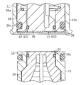
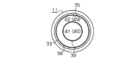
図3に示すように、この雌型コネクタ11のうち、雌側接続口35を介して外側に露出され、且つ雄型コネクタ10と接続される面である、押圧部36の先端面と雌側弁体38の端面とには、吸収体40が熱溶着又は接着剤により固定されている。この吸収体40は、押圧部36の先端面に固定された内側吸収体41と、雌側弁体38の端面に固定された外側吸収体42とから構成される。
図4に示すように、内側吸収体41は、押圧部36の先端面の形状に沿った円形状をなし、該先端面の全域を覆う大きさに形成されている。外側吸収体42は、雌側弁体38の端面の形状に沿った円環状をなし、該端面の全域を覆う大きさに形成されている。また、これらの吸収体41,42の厚さは、ほぼ同一であって、雌側接続口35の端縁に対して若干内側となるような厚さとなっている。
これらの吸収体41,42は、液体を吸収可能であるとともに、圧縮された際に、吸収した液体を放出可能な材質からなる。また、雄型コネクタ10及び雌型コネクタ11に挟持され、且つその端縁がコネクタを流れる液体に曝されても破損しないような物理的及び化学的な耐性を有することが好ましい。例えば、液体に浸蝕性が高い化合物が含まれていない場合には、不織布、ポリビニルアルコール等の樹脂からなる吸収性を有するスポンジ等が好ましい。
次に本実施形態のコネクタの作用について説明する。
まず図1に示すように、雄型コネクタ10と雌型コネクタ11とを、それらの中心軸が一致し且つそれらの接続口20,35が対向するように配置する。そして、図5(a)に示すように、雄型コネクタ10を移動する等して、雄型コネクタ10の接続口20と、雌型コネクタ11の接続口35とを当接させる。この際、雄側ケース18の端面と外側吸収体42とを当接させるとともに、雄側弁体26の先端面と内側吸収体41とを当接させる。
まず図1に示すように、雄型コネクタ10と雌型コネクタ11とを、それらの中心軸が一致し且つそれらの接続口20,35が対向するように配置する。そして、図5(a)に示すように、雄型コネクタ10を移動する等して、雄型コネクタ10の接続口20と、雌型コネクタ11の接続口35とを当接させる。この際、雄側ケース18の端面と外側吸収体42とを当接させるとともに、雄側弁体26の先端面と内側吸収体41とを当接させる。
このように、雄型コネクタ10の接続口20と、雌型コネクタ11の接続口35とを当接させると、雄型コネクタ10を雌型コネクタ11に向かって押圧するか、又は雌型コネクタ11を雄型コネクタ10に向かって押圧する。こうして雌型コネクタ11に雄型コネクタ10を挿入していくと、雄側ケース18が、雌型コネクタ11のバネ39の付勢力に抗して雌側弁体38を押圧し、雌側弁体38を閉位置から雌側ケース33の開口34側へ摺動させる。同時に、雌型コネクタ11の押圧部36が、バネ27の付勢力に抗して雄側弁体26を押圧し、雄側弁体26を閉位置から開口19に向かって摺動させる。
そして、図5(b)に示すように、押圧部36の先端が雄側ケース18に挿入され、雄側弁体26の先端部26bが、雄側ケース18の小径流路21bから脱出すると、雄型コネクタ10の接続口20と押圧部36との間に隙間が生じ、各接続口20,35が押圧部36及び雄側弁体26に閉塞されていない状態、即ち連通状態となる。このため、上記第1外部流路から継手部29の流路30を介して液体が導入された場合、その液体は、押圧部36の本体36aの外周に設けられた流路36cに導入され、押圧部36と雌側接続口35との間を通過する。さらに押圧部36と雄側接続口20の間を介して、雄側弁体26の貫通孔26dを通過し、雄側ケース18の開口19から継手部15の流路16に送出される。そして継手部15の流路16から、第2外部流路に送出される。
このとき押圧部36と雄側弁体26との間に挟持された内側吸収体41は、雄側弁体26がバネ27の付勢力によって押圧部36に圧接されることにより、圧縮された状態となっている。このため、押圧部36と雄側弁体26との間の僅かな隙間に微量の液体が浸入しても、圧縮状態の吸収体41が液体を吸収可能な量は、吸収体41が圧縮されていない状態(以下、自然状態)で吸収することができる量よりも少なく、極めて僅かである。
また、雄側ケース18の端面と雌側弁体38の端面との間に挟持された外側吸収体42も、バネ39の付勢力によって雌側弁体38が雄側ケース18に圧接されることにより、圧縮された状態となっている。このため雄側ケース18と雌側弁体38との間の僅かな隙間に微量の液体が浸入しても、圧縮状態の外側吸収体42が液体を吸収可能な量は、外側吸収体42が自然状態で吸収することができる量よりも少なく、極めて僅かである。
そして、第1外部流路と第2外部流路とを非連通状態とする際には、雄型コネクタ10を雌型コネクタ11から抜出していく。このとき、雄側弁体26は、バネ27の付勢力により雄側接続口20に向かって雄側ケース18内を摺動する。また、雌側弁体38は、バネ39の付勢力により、雌側接続口35に向かって雌側ケース33内を摺動する。
そして、雄側ケース18を雌側ケース33から完全に抜出すると、雄側弁体26が雄側接続口20を閉塞する閉位置に配置されるとともに、雌側弁体38が雌側接続口35を閉塞する閉位置に配置される。この際、各吸収体41,42は、圧縮状態から上記自然状態となることで液体の吸収可能量が増加するので、雄側接続口20及び雌側接続口35付近に存在する液体を吸収しながら、雄側弁体26及び雄側ケース18から離間する。雄側接続口20及び雌側接続口35付近に存在する液体としては、雄側弁体26と押圧部36との隙間に存在する液体、雄側ケース18と雌側弁体38との隙間に存在する液体等である。
また、各シール材18a,26c、36d,38cで各部材間のシール性を維持していても、コネクタが設置される環境の条件や、液体の材質等の諸条件によっては、それらの部材間を介して液体が僅かに押し出されることがある。具体的には、雄側弁体26と雄側ケース18との隙間に存在し、雄側弁体26が雄側接続口20に向かって移動することにより雄側接続口20に押し出された僅かな液体や、押圧部36が雄側接続口20から引き抜かれていくことにより雄側接続口20に残留した僅かな液体等が存在する。このような液体が存在する場合にも、それらの液体を各吸収体41,42によって吸収することができる。
このように、雄型コネクタ10及び雌型コネクタ11が離間する際に、各吸収体41,42により雄側接続口20付近の液体が吸い取られるので、雄型コネクタ10のうち、雄側ケース18の端面、雄側弁体26の先端面等といった外部に露出されている接続面に、滴状に液体が付着したり、液体が濡れ広がったりすることが防止される。また、雌型コネクタ11の押圧部36の先端面、雌側弁体38の端面には各吸収体41,42が直接固定されているので、雌側ケース33の端面、押圧部36の先端面、雌側弁体38の端面等といった外部に露出されている接続面にも、滴状に液体が付着したり、液体が濡れ広がったりすることがない。このため、雄型コネクタ10及び雌型コネクタ11の各接続面に塵埃が付着しやすくなることを抑制することができる。
また、各吸収体41,42により吸収される液体量は微量であって、各吸収体41,42が液体を吸収しきった飽和状態となることはない。しかし、例え吸収量が多くなったとしても、雌側接続口35の端縁に対して若干内側となるように設けられているので、雌型コネクタ11が周囲の物体に接触しても、各吸収体41,42に吸収された液体がその物体に付着しない。
(1)第1実施形態では、雌型コネクタ11が雄型コネクタ10に接続する接続面に、液体を吸収する吸収体41,42を備えた。このため、雄型コネクタ10及び雌型コネクタ11の連結を解除する際に、雄型コネクタ10及び雌型コネクタ11の隙間に浸入していた液体等といった僅かな液体をその吸収体41,42によって吸収することができる。従って、連結が解除された雄型コネクタ10及び雌型コネクタ11の各接続面に液体が付着することを防止し、各接続面が塵埃が吸着しやすい状態となることを抑制することができる。
(2)内側吸収体41を、雄側ケース18の端面(接続面)と当接する雌側弁体38の端面に備えたので、雄型コネクタ10及び雌型コネクタ11を連結した際に、内側吸収体41は、雌側弁体38と雄側ケースとの間に挟持された状態となる。このため、内側吸収体41は、雌側弁体38を閉位置に付勢するバネ39の付勢力により、雌側弁体38と雄側ケース18との間で圧縮されるので、その状態で内側吸収体41が吸収可能な液体量は、自然状態の内側吸収体41が吸収可能な液体量よりも少なくなる。このため、雄型コネクタ10及び雌型コネクタ11の連結を解除した際には、内側吸収体41は液体を吸収する余地がある状態であり、接続口20,35付近に浸入した液体を吸収しやすくなる。
(3)外側吸収体42を、雄側弁体26の先端面と当接する押圧部36の先端面に備えたので、雄型コネクタ10及び雌型コネクタ11を連結した際に、外側吸収体42は、雄側弁体26と押圧部36との間に挟持された状態となる。このため、外側吸収体42は、雄側弁体26を閉位置に付勢するバネ27の付勢力により、雄側弁体26と押圧部36との間で圧縮されるので、その状態で外側吸収体42が吸収可能な液体量は、自然状態の外側吸収体42が吸収可能な液体量よりも少なくなる。このため、雄型コネクタ10及び雌型コネクタ11の連結を解除した際には、外側吸収体42は液体を吸収する余地がある状態であり、接続口20,35付近に浸入した液体を吸収しやすくなる。
(4)各吸収体41,42は伸縮可能な材質からなるため、雄型コネクタ10及び雌型コネクタ11を連結した際には、それらの接続面の間で圧縮された状態となり、連結を解除した際には、圧縮状態から元の自然状態に戻る。そして吸収体41,42が圧縮された状態では、自然状態よりも、液体の吸収量が少なくなる。このため、雄型コネクタ10及び雌型コネクタ11の連結を解除した際には、吸収体41,42は液体を吸収する余地がある状態であり、接続口20,35付近に浸入した液体を吸収することができる。
(5)吸収体41,42は、連結が解除された雄型コネクタ10又は雌型コネクタ11に、外部に露出された状態で備えられている。即ち、吸収体41,42が備えられていない状態では、その面に液体が付着した場合に、その液体が周囲に付着してしまう虞があるが、吸収体41,42が備えられることで液体を吸収することができるので、外部に露出される液体が無く、液体の周囲への付着を抑制することができる。
(第2実施形態)
次に、本発明を具体化した第2実施形態を図6にしたがって説明する。尚、第2実施形態は、第1実施形態の吸収体を変更したのみの構成であるため、同様の部分については同一符号を付してその詳細な説明を省略する。
次に、本発明を具体化した第2実施形態を図6にしたがって説明する。尚、第2実施形態は、第1実施形態の吸収体を変更したのみの構成であるため、同様の部分については同一符号を付してその詳細な説明を省略する。
図6に示すように、本実施形態では、雌型コネクタ11だけでなく、雄型コネクタ10にも吸収体50が固定されている。雄型コネクタ10に固定された吸収体50は、内側吸収体51及び外側吸収体52から構成される。内側吸収体51は、略円形状に形成され、雄側弁体26の先端面に固定されている。
外側吸収体52は、略円環状に形成され、雄側ケース18の端面に固定されている。各吸収体51,52の厚さは、雌型コネクタ11に固定された各吸収体41,42の厚さと同一であり、各吸収体41,42,51,52の材質は、同一となっている。
雄型コネクタ10及び雌型コネクタ11を連結した状態では、雄型コネクタ10の内側吸収体51と雌型コネクタ11の内側吸収体41が、雄側弁体26と押圧部36との間に挟持されて圧縮される。また、雄型コネクタ10の外側吸収体52と雌型コネクタ11の外側吸収体42は、雄側ケース18と雌側弁体38との間に挟持されて圧縮される。
雄型コネクタ10及び雌型コネクタ11の連結を解除する際には、各吸収体41,42により雌側接続口35付近の液体が吸収され、各吸収体51,52により雄側接続口20付近の液体が吸収されるので、各接続口20,35付近に、滴状に液体が付着したり、液体が濡れ広がったりすることがない。このため、液体の付着によって接続口20,35に塵埃が付着しやすくなることを防止することができる。
従って、第2実施形態によれば、第1実施形態の(1)~(5)に記載の効果に加えて以下の効果を得ることができる。
(6)第2実施形態によれば、雄型コネクタ10が雌型コネクタ11に接続する接続面に、液体を吸収する吸収体51,52を備えた。このため、雄型コネクタ10及び雌型コネクタ11の連結を解除する際に、雄型コネクタ10及び雌型コネクタ11の隙間に浸入していた液体等といった僅かな液体をその吸収体51,52によって吸収することができる。従って、連結が解除された雄型コネクタ10及び雌型コネクタ11の各接続面に液体が付着することを防止し、各接続面が塵埃が吸着しやすい状態となることを抑制することができる。
(6)第2実施形態によれば、雄型コネクタ10が雌型コネクタ11に接続する接続面に、液体を吸収する吸収体51,52を備えた。このため、雄型コネクタ10及び雌型コネクタ11の連結を解除する際に、雄型コネクタ10及び雌型コネクタ11の隙間に浸入していた液体等といった僅かな液体をその吸収体51,52によって吸収することができる。従って、連結が解除された雄型コネクタ10及び雌型コネクタ11の各接続面に液体が付着することを防止し、各接続面が塵埃が吸着しやすい状態となることを抑制することができる。
尚、上記各実施形態は以下のように変更してもよい。
上記各実施形態では、付勢部を、コイル状のバネ27,39に具体化したが、雄側弁体26及び雌側弁体38を閉位置に付勢可能であれば、その他の構成でもよい。
上記各実施形態では、付勢部を、コイル状のバネ27,39に具体化したが、雄側弁体26及び雌側弁体38を閉位置に付勢可能であれば、その他の構成でもよい。
上記実施形態では、雌型コネクタ11から雄型コネクタ10へ向かって液体を流すようにしたが、雄型コネクタ10から雌型コネクタ11へ向かって液体を流すようにしてもよい。
各吸収体41,42は、その表面が、雌側接続口35の端縁よりも若干内側となるような厚さとしたが、雌側接続口35の端縁から突出しないような厚さであればよい。
上記各実施形態では、複数の吸収体を備えたが、一つでもよい。例えば、押圧部36の先端にのみ固定するようにしてもよい。また、接続面の全域を覆うように吸収体を固定したが、一部のみ覆うように固定してもよい。例えば、雄側弁体26の先端部及び雄側ケース18の端面のいずれか一方に固定してもよいし、押圧部36の先端面及び雌側弁体38の端面のいずれか一方に固定してもよい。
上記各実施形態では、複数の吸収体を備えたが、一つでもよい。例えば、押圧部36の先端にのみ固定するようにしてもよい。また、接続面の全域を覆うように吸収体を固定したが、一部のみ覆うように固定してもよい。例えば、雄側弁体26の先端部及び雄側ケース18の端面のいずれか一方に固定してもよいし、押圧部36の先端面及び雌側弁体38の端面のいずれか一方に固定してもよい。
コネクタの構成は、上記各実施形態以外の構成でもよい。例えば、雄型コネクタは、該雄型コネクタが接続される部材と一体に形成されたケース内に雄側弁機構を備え、その部材に内蔵された構成でもよい。また、雌型コネクタは、該雌型コネクタが接続される部材と一体に形成されたケース内に雌側弁機構を備え、その部材に内蔵された構成でもよい。即ち、雄型コネクタの接続面及び雌側コネクタの接続面の少なくとも一方に、液体を吸収可能な吸収体を固定した構成であればよい。
2011年6月1日に出願された日本特許出願第2011-123280号の明細書、特許請求の範囲、図面及び要約書の全内容をここに引用し、本発明の明細書の開示として、取り入れるものである。
2011年6月1日に出願された日本特許出願第2011-123280号の明細書、特許請求の範囲、図面及び要約書の全内容をここに引用し、本発明の明細書の開示として、取り入れるものである。
Claims (5)
- 液体が流れる流路を有する雄側ケースと該雄側ケース内に備えられた雄側弁機構とを有する雄型コネクタと、
液体が流れる流路を有する雌側ケースと該雌側ケース内に備えられた雌側弁機構とを有する雌型コネクタとを備え、
前記雄型コネクタ及び前記雌型コネクタの連結が解除された際に前記雄側弁機構及び前記雌側弁機構を閉状態とするコネクタにおいて、
前記雄型コネクタに備えられ前記雌型コネクタと接続する接続面及び前記雌型コネクタに備えられ前記雄型コネクタに接続する接続面のうち少なくとも一方に、前記液体を吸収する吸収体を備えたことを特徴とするコネクタ。 - 前記雄側弁機構及び前記雌側弁機構は、前記雄型コネクタ及び前記雌型コネクタが連結される際に、対向する前記接続面と当接する弁体と、該弁体を前記流路が非連通状態となる閉位置に付勢する付勢部とをそれぞれ備え、
前記吸収体は、前記各弁体の少なくとも一方に備えられる請求項1に記載のコネクタ。 - 前記雄型コネクタ及び前記雌型コネクタは、互いに連結される際に、前記雄側弁機構及び前記雌側弁機構に備えられた各弁体と当接する接続面をそれぞれ有し、
前記吸収体は、前記弁体と当接する各接続面の少なくとも一方に備えられる請求項1又は2に記載のコネクタ。 - 前記吸収体は、伸縮可能な材質からなる請求項1~3のいずれか1項に記載のコネクタ。
- 前記吸収体は、連結が解除された前記雄型コネクタ又は前記雌型コネクタのうち外部に露出される接続面を覆う請求項1~4のいずれか1項に記載のコネクタ。
Applications Claiming Priority (2)
| Application Number | Priority Date | Filing Date | Title |
|---|---|---|---|
| JP2011-123280 | 2011-06-01 | ||
| JP2011123280A JP2012251580A (ja) | 2011-06-01 | 2011-06-01 | コネクタ |
Publications (1)
| Publication Number | Publication Date |
|---|---|
| WO2012165391A1 true WO2012165391A1 (ja) | 2012-12-06 |
Family
ID=47259247
Family Applications (1)
| Application Number | Title | Priority Date | Filing Date |
|---|---|---|---|
| PCT/JP2012/063671 Ceased WO2012165391A1 (ja) | 2011-06-01 | 2012-05-28 | コネクタ |
Country Status (2)
| Country | Link |
|---|---|
| JP (1) | JP2012251580A (ja) |
| WO (1) | WO2012165391A1 (ja) |
Cited By (1)
| Publication number | Priority date | Publication date | Assignee | Title |
|---|---|---|---|---|
| US20250251072A1 (en) * | 2024-02-01 | 2025-08-07 | Fositek Corporation | Quick coupler assembly |
Citations (2)
| Publication number | Priority date | Publication date | Assignee | Title |
|---|---|---|---|---|
| JP3529562B2 (ja) * | 1996-08-26 | 2004-05-24 | 東洋エンジニアリング株式会社 | 流体用継手 |
| JP2007087653A (ja) * | 2005-09-20 | 2007-04-05 | Toshiba Corp | 漏洩防止構造 |
-
2011
- 2011-06-01 JP JP2011123280A patent/JP2012251580A/ja not_active Withdrawn
-
2012
- 2012-05-28 WO PCT/JP2012/063671 patent/WO2012165391A1/ja not_active Ceased
Patent Citations (2)
| Publication number | Priority date | Publication date | Assignee | Title |
|---|---|---|---|---|
| JP3529562B2 (ja) * | 1996-08-26 | 2004-05-24 | 東洋エンジニアリング株式会社 | 流体用継手 |
| JP2007087653A (ja) * | 2005-09-20 | 2007-04-05 | Toshiba Corp | 漏洩防止構造 |
Cited By (2)
| Publication number | Priority date | Publication date | Assignee | Title |
|---|---|---|---|---|
| US20250251072A1 (en) * | 2024-02-01 | 2025-08-07 | Fositek Corporation | Quick coupler assembly |
| US12429154B2 (en) * | 2024-02-01 | 2025-09-30 | Fositek Corporation | Quick coupler assembly |
Also Published As
| Publication number | Publication date |
|---|---|
| JP2012251580A (ja) | 2012-12-20 |
Similar Documents
| Publication | Publication Date | Title |
|---|---|---|
| US9032997B2 (en) | Fluid coupling | |
| US8196606B2 (en) | Coupling member for pipe coupling | |
| JP6506500B2 (ja) | クイックカプラ | |
| TWI463089B (zh) | 內孔耦接元件及包含此元件之快速耦接器 | |
| JP2021504109A5 (ja) | ||
| WO2011040454A1 (ja) | 管継手の雌型継手部材 | |
| CN106907541A (zh) | 用于连接引导流体的管道的耦联元件以及相应的耦联装置 | |
| CN216242528U (zh) | 防爆阀 | |
| WO2012165391A1 (ja) | コネクタ | |
| WO2012037858A1 (zh) | 一种具有补气结构的气动按钮 | |
| JP2015108405A5 (ja) | ||
| CN105277868B (zh) | 测试装置 | |
| US20080295841A1 (en) | Connection head for an absorber of an anesthetic breathing system | |
| CN108799667B (zh) | 一种液路自密封的断接器插座及断接器 | |
| JP2013543427A (ja) | マイクロ流体チップの流体接触のための接続構造 | |
| JP5566759B2 (ja) | 弁付き配管継手 | |
| WO2012173151A1 (ja) | コネクタ | |
| JP2015086885A (ja) | 管継手 | |
| CN104334477B (zh) | 密封滑动双开门连接处垫圈及其操作方法 | |
| TWI596287B (zh) | Damper | |
| CN210050190U (zh) | 吸附装置 | |
| JP4792372B2 (ja) | ガス供給用接続具におけるプラグ | |
| JP2017009039A (ja) | ガス栓 | |
| JP6223051B2 (ja) | ガス栓 | |
| KR102328426B1 (ko) | 유압 제어식 클러치 베어링 |
Legal Events
| Date | Code | Title | Description |
|---|---|---|---|
| 121 | Ep: the epo has been informed by wipo that ep was designated in this application |
Ref document number: 12792425 Country of ref document: EP Kind code of ref document: A1 |
|
| NENP | Non-entry into the national phase |
Ref country code: DE |
|
| 122 | Ep: pct application non-entry in european phase |
Ref document number: 12792425 Country of ref document: EP Kind code of ref document: A1 |