WO2012165046A1 - 電気駆動ダンプトラック - Google Patents
電気駆動ダンプトラック Download PDFInfo
- Publication number
- WO2012165046A1 WO2012165046A1 PCT/JP2012/059409 JP2012059409W WO2012165046A1 WO 2012165046 A1 WO2012165046 A1 WO 2012165046A1 JP 2012059409 W JP2012059409 W JP 2012059409W WO 2012165046 A1 WO2012165046 A1 WO 2012165046A1
- Authority
- WO
- WIPO (PCT)
- Prior art keywords
- vehicle
- trolley
- yaw moment
- dump truck
- control
- Prior art date
- Legal status (The legal status is an assumption and is not a legal conclusion. Google has not performed a legal analysis and makes no representation as to the accuracy of the status listed.)
- Ceased
Links
Images











Classifications
-
- B—PERFORMING OPERATIONS; TRANSPORTING
- B60—VEHICLES IN GENERAL
- B60L—PROPULSION OF ELECTRICALLY-PROPELLED VEHICLES; SUPPLYING ELECTRIC POWER FOR AUXILIARY EQUIPMENT OF ELECTRICALLY-PROPELLED VEHICLES; ELECTRODYNAMIC BRAKE SYSTEMS FOR VEHICLES IN GENERAL; MAGNETIC SUSPENSION OR LEVITATION FOR VEHICLES; MONITORING OPERATING VARIABLES OF ELECTRICALLY-PROPELLED VEHICLES; ELECTRIC SAFETY DEVICES FOR ELECTRICALLY-PROPELLED VEHICLES
- B60L9/00—Electric propulsion with power supply external to the vehicle
- B60L9/16—Electric propulsion with power supply external to the vehicle using AC induction motors
- B60L9/18—Electric propulsion with power supply external to the vehicle using AC induction motors fed from DC supply lines
-
- B—PERFORMING OPERATIONS; TRANSPORTING
- B60—VEHICLES IN GENERAL
- B60L—PROPULSION OF ELECTRICALLY-PROPELLED VEHICLES; SUPPLYING ELECTRIC POWER FOR AUXILIARY EQUIPMENT OF ELECTRICALLY-PROPELLED VEHICLES; ELECTRODYNAMIC BRAKE SYSTEMS FOR VEHICLES IN GENERAL; MAGNETIC SUSPENSION OR LEVITATION FOR VEHICLES; MONITORING OPERATING VARIABLES OF ELECTRICALLY-PROPELLED VEHICLES; ELECTRIC SAFETY DEVICES FOR ELECTRICALLY-PROPELLED VEHICLES
- B60L1/00—Supplying electric power to auxiliary equipment of vehicles
- B60L1/003—Supplying electric power to auxiliary equipment of vehicles to auxiliary motors, e.g. for pumps, compressors
-
- B—PERFORMING OPERATIONS; TRANSPORTING
- B60—VEHICLES IN GENERAL
- B60L—PROPULSION OF ELECTRICALLY-PROPELLED VEHICLES; SUPPLYING ELECTRIC POWER FOR AUXILIARY EQUIPMENT OF ELECTRICALLY-PROPELLED VEHICLES; ELECTRODYNAMIC BRAKE SYSTEMS FOR VEHICLES IN GENERAL; MAGNETIC SUSPENSION OR LEVITATION FOR VEHICLES; MONITORING OPERATING VARIABLES OF ELECTRICALLY-PROPELLED VEHICLES; ELECTRIC SAFETY DEVICES FOR ELECTRICALLY-PROPELLED VEHICLES
- B60L15/00—Methods, circuits, or devices for controlling the traction-motor speed of electrically-propelled vehicles
- B60L15/20—Methods, circuits, or devices for controlling the traction-motor speed of electrically-propelled vehicles for control of the vehicle or its driving motor to achieve a desired performance, e.g. speed, torque, programmed variation of speed
-
- B—PERFORMING OPERATIONS; TRANSPORTING
- B60—VEHICLES IN GENERAL
- B60L—PROPULSION OF ELECTRICALLY-PROPELLED VEHICLES; SUPPLYING ELECTRIC POWER FOR AUXILIARY EQUIPMENT OF ELECTRICALLY-PROPELLED VEHICLES; ELECTRODYNAMIC BRAKE SYSTEMS FOR VEHICLES IN GENERAL; MAGNETIC SUSPENSION OR LEVITATION FOR VEHICLES; MONITORING OPERATING VARIABLES OF ELECTRICALLY-PROPELLED VEHICLES; ELECTRIC SAFETY DEVICES FOR ELECTRICALLY-PROPELLED VEHICLES
- B60L15/00—Methods, circuits, or devices for controlling the traction-motor speed of electrically-propelled vehicles
- B60L15/20—Methods, circuits, or devices for controlling the traction-motor speed of electrically-propelled vehicles for control of the vehicle or its driving motor to achieve a desired performance, e.g. speed, torque, programmed variation of speed
- B60L15/2036—Electric differentials, e.g. for supporting steering vehicles
-
- B—PERFORMING OPERATIONS; TRANSPORTING
- B60—VEHICLES IN GENERAL
- B60L—PROPULSION OF ELECTRICALLY-PROPELLED VEHICLES; SUPPLYING ELECTRIC POWER FOR AUXILIARY EQUIPMENT OF ELECTRICALLY-PROPELLED VEHICLES; ELECTRODYNAMIC BRAKE SYSTEMS FOR VEHICLES IN GENERAL; MAGNETIC SUSPENSION OR LEVITATION FOR VEHICLES; MONITORING OPERATING VARIABLES OF ELECTRICALLY-PROPELLED VEHICLES; ELECTRIC SAFETY DEVICES FOR ELECTRICALLY-PROPELLED VEHICLES
- B60L5/00—Current collectors for power supply lines of electrically-propelled vehicles
- B60L5/04—Current collectors for power supply lines of electrically-propelled vehicles using rollers or sliding shoes in contact with trolley wire
- B60L5/045—Current collectors for power supply lines of electrically-propelled vehicles using rollers or sliding shoes in contact with trolley wire with trolley wire finders
-
- B—PERFORMING OPERATIONS; TRANSPORTING
- B60—VEHICLES IN GENERAL
- B60L—PROPULSION OF ELECTRICALLY-PROPELLED VEHICLES; SUPPLYING ELECTRIC POWER FOR AUXILIARY EQUIPMENT OF ELECTRICALLY-PROPELLED VEHICLES; ELECTRODYNAMIC BRAKE SYSTEMS FOR VEHICLES IN GENERAL; MAGNETIC SUSPENSION OR LEVITATION FOR VEHICLES; MONITORING OPERATING VARIABLES OF ELECTRICALLY-PROPELLED VEHICLES; ELECTRIC SAFETY DEVICES FOR ELECTRICALLY-PROPELLED VEHICLES
- B60L5/00—Current collectors for power supply lines of electrically-propelled vehicles
- B60L5/36—Current collectors for power supply lines of electrically-propelled vehicles with means for collecting current simultaneously from more than one conductor, e.g. from more than one phase
-
- B—PERFORMING OPERATIONS; TRANSPORTING
- B60—VEHICLES IN GENERAL
- B60L—PROPULSION OF ELECTRICALLY-PROPELLED VEHICLES; SUPPLYING ELECTRIC POWER FOR AUXILIARY EQUIPMENT OF ELECTRICALLY-PROPELLED VEHICLES; ELECTRODYNAMIC BRAKE SYSTEMS FOR VEHICLES IN GENERAL; MAGNETIC SUSPENSION OR LEVITATION FOR VEHICLES; MONITORING OPERATING VARIABLES OF ELECTRICALLY-PROPELLED VEHICLES; ELECTRIC SAFETY DEVICES FOR ELECTRICALLY-PROPELLED VEHICLES
- B60L50/00—Electric propulsion with power supplied within the vehicle
- B60L50/40—Electric propulsion with power supplied within the vehicle using propulsion power supplied by capacitors
-
- B—PERFORMING OPERATIONS; TRANSPORTING
- B60—VEHICLES IN GENERAL
- B60L—PROPULSION OF ELECTRICALLY-PROPELLED VEHICLES; SUPPLYING ELECTRIC POWER FOR AUXILIARY EQUIPMENT OF ELECTRICALLY-PROPELLED VEHICLES; ELECTRODYNAMIC BRAKE SYSTEMS FOR VEHICLES IN GENERAL; MAGNETIC SUSPENSION OR LEVITATION FOR VEHICLES; MONITORING OPERATING VARIABLES OF ELECTRICALLY-PROPELLED VEHICLES; ELECTRIC SAFETY DEVICES FOR ELECTRICALLY-PROPELLED VEHICLES
- B60L50/00—Electric propulsion with power supplied within the vehicle
- B60L50/50—Electric propulsion with power supplied within the vehicle using propulsion power supplied by batteries or fuel cells
- B60L50/60—Electric propulsion with power supplied within the vehicle using propulsion power supplied by batteries or fuel cells using power supplied by batteries
- B60L50/61—Electric propulsion with power supplied within the vehicle using propulsion power supplied by batteries or fuel cells using power supplied by batteries by batteries charged by engine-driven generators, e.g. series hybrid electric vehicles
-
- B—PERFORMING OPERATIONS; TRANSPORTING
- B60—VEHICLES IN GENERAL
- B60L—PROPULSION OF ELECTRICALLY-PROPELLED VEHICLES; SUPPLYING ELECTRIC POWER FOR AUXILIARY EQUIPMENT OF ELECTRICALLY-PROPELLED VEHICLES; ELECTRODYNAMIC BRAKE SYSTEMS FOR VEHICLES IN GENERAL; MAGNETIC SUSPENSION OR LEVITATION FOR VEHICLES; MONITORING OPERATING VARIABLES OF ELECTRICALLY-PROPELLED VEHICLES; ELECTRIC SAFETY DEVICES FOR ELECTRICALLY-PROPELLED VEHICLES
- B60L53/00—Methods of charging batteries, specially adapted for electric vehicles; Charging stations or on-board charging equipment therefor; Exchange of energy storage elements in electric vehicles
- B60L53/30—Constructional details of charging stations
- B60L53/35—Means for automatic or assisted adjustment of the relative position of charging devices and vehicles
-
- B—PERFORMING OPERATIONS; TRANSPORTING
- B60—VEHICLES IN GENERAL
- B60L—PROPULSION OF ELECTRICALLY-PROPELLED VEHICLES; SUPPLYING ELECTRIC POWER FOR AUXILIARY EQUIPMENT OF ELECTRICALLY-PROPELLED VEHICLES; ELECTRODYNAMIC BRAKE SYSTEMS FOR VEHICLES IN GENERAL; MAGNETIC SUSPENSION OR LEVITATION FOR VEHICLES; MONITORING OPERATING VARIABLES OF ELECTRICALLY-PROPELLED VEHICLES; ELECTRIC SAFETY DEVICES FOR ELECTRICALLY-PROPELLED VEHICLES
- B60L9/00—Electric propulsion with power supply external to the vehicle
- B60L9/16—Electric propulsion with power supply external to the vehicle using AC induction motors
- B60L9/24—Electric propulsion with power supply external to the vehicle using AC induction motors fed from AC supply lines
-
- B—PERFORMING OPERATIONS; TRANSPORTING
- B60—VEHICLES IN GENERAL
- B60L—PROPULSION OF ELECTRICALLY-PROPELLED VEHICLES; SUPPLYING ELECTRIC POWER FOR AUXILIARY EQUIPMENT OF ELECTRICALLY-PROPELLED VEHICLES; ELECTRODYNAMIC BRAKE SYSTEMS FOR VEHICLES IN GENERAL; MAGNETIC SUSPENSION OR LEVITATION FOR VEHICLES; MONITORING OPERATING VARIABLES OF ELECTRICALLY-PROPELLED VEHICLES; ELECTRIC SAFETY DEVICES FOR ELECTRICALLY-PROPELLED VEHICLES
- B60L2200/00—Type of vehicles
- B60L2200/36—Vehicles designed to transport cargo, e.g. trucks
-
- B—PERFORMING OPERATIONS; TRANSPORTING
- B60—VEHICLES IN GENERAL
- B60L—PROPULSION OF ELECTRICALLY-PROPELLED VEHICLES; SUPPLYING ELECTRIC POWER FOR AUXILIARY EQUIPMENT OF ELECTRICALLY-PROPELLED VEHICLES; ELECTRODYNAMIC BRAKE SYSTEMS FOR VEHICLES IN GENERAL; MAGNETIC SUSPENSION OR LEVITATION FOR VEHICLES; MONITORING OPERATING VARIABLES OF ELECTRICALLY-PROPELLED VEHICLES; ELECTRIC SAFETY DEVICES FOR ELECTRICALLY-PROPELLED VEHICLES
- B60L2210/00—Converter types
- B60L2210/30—AC to DC converters
-
- B—PERFORMING OPERATIONS; TRANSPORTING
- B60—VEHICLES IN GENERAL
- B60L—PROPULSION OF ELECTRICALLY-PROPELLED VEHICLES; SUPPLYING ELECTRIC POWER FOR AUXILIARY EQUIPMENT OF ELECTRICALLY-PROPELLED VEHICLES; ELECTRODYNAMIC BRAKE SYSTEMS FOR VEHICLES IN GENERAL; MAGNETIC SUSPENSION OR LEVITATION FOR VEHICLES; MONITORING OPERATING VARIABLES OF ELECTRICALLY-PROPELLED VEHICLES; ELECTRIC SAFETY DEVICES FOR ELECTRICALLY-PROPELLED VEHICLES
- B60L2210/00—Converter types
- B60L2210/40—DC to AC converters
-
- B—PERFORMING OPERATIONS; TRANSPORTING
- B60—VEHICLES IN GENERAL
- B60L—PROPULSION OF ELECTRICALLY-PROPELLED VEHICLES; SUPPLYING ELECTRIC POWER FOR AUXILIARY EQUIPMENT OF ELECTRICALLY-PROPELLED VEHICLES; ELECTRODYNAMIC BRAKE SYSTEMS FOR VEHICLES IN GENERAL; MAGNETIC SUSPENSION OR LEVITATION FOR VEHICLES; MONITORING OPERATING VARIABLES OF ELECTRICALLY-PROPELLED VEHICLES; ELECTRIC SAFETY DEVICES FOR ELECTRICALLY-PROPELLED VEHICLES
- B60L2220/00—Electrical machine types; Structures or applications thereof
- B60L2220/40—Electrical machine applications
- B60L2220/44—Wheel Hub motors, i.e. integrated in the wheel hub
-
- B—PERFORMING OPERATIONS; TRANSPORTING
- B60—VEHICLES IN GENERAL
- B60L—PROPULSION OF ELECTRICALLY-PROPELLED VEHICLES; SUPPLYING ELECTRIC POWER FOR AUXILIARY EQUIPMENT OF ELECTRICALLY-PROPELLED VEHICLES; ELECTRODYNAMIC BRAKE SYSTEMS FOR VEHICLES IN GENERAL; MAGNETIC SUSPENSION OR LEVITATION FOR VEHICLES; MONITORING OPERATING VARIABLES OF ELECTRICALLY-PROPELLED VEHICLES; ELECTRIC SAFETY DEVICES FOR ELECTRICALLY-PROPELLED VEHICLES
- B60L2240/00—Control parameters of input or output; Target parameters
- B60L2240/10—Vehicle control parameters
- B60L2240/12—Speed
-
- B—PERFORMING OPERATIONS; TRANSPORTING
- B60—VEHICLES IN GENERAL
- B60L—PROPULSION OF ELECTRICALLY-PROPELLED VEHICLES; SUPPLYING ELECTRIC POWER FOR AUXILIARY EQUIPMENT OF ELECTRICALLY-PROPELLED VEHICLES; ELECTRODYNAMIC BRAKE SYSTEMS FOR VEHICLES IN GENERAL; MAGNETIC SUSPENSION OR LEVITATION FOR VEHICLES; MONITORING OPERATING VARIABLES OF ELECTRICALLY-PROPELLED VEHICLES; ELECTRIC SAFETY DEVICES FOR ELECTRICALLY-PROPELLED VEHICLES
- B60L2240/00—Control parameters of input or output; Target parameters
- B60L2240/10—Vehicle control parameters
- B60L2240/14—Acceleration
- B60L2240/16—Acceleration longitudinal
-
- B—PERFORMING OPERATIONS; TRANSPORTING
- B60—VEHICLES IN GENERAL
- B60L—PROPULSION OF ELECTRICALLY-PROPELLED VEHICLES; SUPPLYING ELECTRIC POWER FOR AUXILIARY EQUIPMENT OF ELECTRICALLY-PROPELLED VEHICLES; ELECTRODYNAMIC BRAKE SYSTEMS FOR VEHICLES IN GENERAL; MAGNETIC SUSPENSION OR LEVITATION FOR VEHICLES; MONITORING OPERATING VARIABLES OF ELECTRICALLY-PROPELLED VEHICLES; ELECTRIC SAFETY DEVICES FOR ELECTRICALLY-PROPELLED VEHICLES
- B60L2240/00—Control parameters of input or output; Target parameters
- B60L2240/10—Vehicle control parameters
- B60L2240/14—Acceleration
- B60L2240/20—Acceleration angular
-
- B—PERFORMING OPERATIONS; TRANSPORTING
- B60—VEHICLES IN GENERAL
- B60L—PROPULSION OF ELECTRICALLY-PROPELLED VEHICLES; SUPPLYING ELECTRIC POWER FOR AUXILIARY EQUIPMENT OF ELECTRICALLY-PROPELLED VEHICLES; ELECTRODYNAMIC BRAKE SYSTEMS FOR VEHICLES IN GENERAL; MAGNETIC SUSPENSION OR LEVITATION FOR VEHICLES; MONITORING OPERATING VARIABLES OF ELECTRICALLY-PROPELLED VEHICLES; ELECTRIC SAFETY DEVICES FOR ELECTRICALLY-PROPELLED VEHICLES
- B60L2240/00—Control parameters of input or output; Target parameters
- B60L2240/10—Vehicle control parameters
- B60L2240/22—Yaw angle
-
- B—PERFORMING OPERATIONS; TRANSPORTING
- B60—VEHICLES IN GENERAL
- B60L—PROPULSION OF ELECTRICALLY-PROPELLED VEHICLES; SUPPLYING ELECTRIC POWER FOR AUXILIARY EQUIPMENT OF ELECTRICALLY-PROPELLED VEHICLES; ELECTRODYNAMIC BRAKE SYSTEMS FOR VEHICLES IN GENERAL; MAGNETIC SUSPENSION OR LEVITATION FOR VEHICLES; MONITORING OPERATING VARIABLES OF ELECTRICALLY-PROPELLED VEHICLES; ELECTRIC SAFETY DEVICES FOR ELECTRICALLY-PROPELLED VEHICLES
- B60L2240/00—Control parameters of input or output; Target parameters
- B60L2240/10—Vehicle control parameters
- B60L2240/24—Steering angle
-
- B—PERFORMING OPERATIONS; TRANSPORTING
- B60—VEHICLES IN GENERAL
- B60L—PROPULSION OF ELECTRICALLY-PROPELLED VEHICLES; SUPPLYING ELECTRIC POWER FOR AUXILIARY EQUIPMENT OF ELECTRICALLY-PROPELLED VEHICLES; ELECTRODYNAMIC BRAKE SYSTEMS FOR VEHICLES IN GENERAL; MAGNETIC SUSPENSION OR LEVITATION FOR VEHICLES; MONITORING OPERATING VARIABLES OF ELECTRICALLY-PROPELLED VEHICLES; ELECTRIC SAFETY DEVICES FOR ELECTRICALLY-PROPELLED VEHICLES
- B60L2240/00—Control parameters of input or output; Target parameters
- B60L2240/40—Drive Train control parameters
- B60L2240/42—Drive Train control parameters related to electric machines
- B60L2240/421—Speed
-
- B—PERFORMING OPERATIONS; TRANSPORTING
- B60—VEHICLES IN GENERAL
- B60L—PROPULSION OF ELECTRICALLY-PROPELLED VEHICLES; SUPPLYING ELECTRIC POWER FOR AUXILIARY EQUIPMENT OF ELECTRICALLY-PROPELLED VEHICLES; ELECTRODYNAMIC BRAKE SYSTEMS FOR VEHICLES IN GENERAL; MAGNETIC SUSPENSION OR LEVITATION FOR VEHICLES; MONITORING OPERATING VARIABLES OF ELECTRICALLY-PROPELLED VEHICLES; ELECTRIC SAFETY DEVICES FOR ELECTRICALLY-PROPELLED VEHICLES
- B60L2240/00—Control parameters of input or output; Target parameters
- B60L2240/40—Drive Train control parameters
- B60L2240/42—Drive Train control parameters related to electric machines
- B60L2240/423—Torque
-
- B—PERFORMING OPERATIONS; TRANSPORTING
- B60—VEHICLES IN GENERAL
- B60L—PROPULSION OF ELECTRICALLY-PROPELLED VEHICLES; SUPPLYING ELECTRIC POWER FOR AUXILIARY EQUIPMENT OF ELECTRICALLY-PROPELLED VEHICLES; ELECTRODYNAMIC BRAKE SYSTEMS FOR VEHICLES IN GENERAL; MAGNETIC SUSPENSION OR LEVITATION FOR VEHICLES; MONITORING OPERATING VARIABLES OF ELECTRICALLY-PROPELLED VEHICLES; ELECTRIC SAFETY DEVICES FOR ELECTRICALLY-PROPELLED VEHICLES
- B60L2240/00—Control parameters of input or output; Target parameters
- B60L2240/40—Drive Train control parameters
- B60L2240/44—Drive Train control parameters related to combustion engines
- B60L2240/441—Speed
-
- B—PERFORMING OPERATIONS; TRANSPORTING
- B60—VEHICLES IN GENERAL
- B60L—PROPULSION OF ELECTRICALLY-PROPELLED VEHICLES; SUPPLYING ELECTRIC POWER FOR AUXILIARY EQUIPMENT OF ELECTRICALLY-PROPELLED VEHICLES; ELECTRODYNAMIC BRAKE SYSTEMS FOR VEHICLES IN GENERAL; MAGNETIC SUSPENSION OR LEVITATION FOR VEHICLES; MONITORING OPERATING VARIABLES OF ELECTRICALLY-PROPELLED VEHICLES; ELECTRIC SAFETY DEVICES FOR ELECTRICALLY-PROPELLED VEHICLES
- B60L2240/00—Control parameters of input or output; Target parameters
- B60L2240/40—Drive Train control parameters
- B60L2240/44—Drive Train control parameters related to combustion engines
- B60L2240/443—Torque
-
- B—PERFORMING OPERATIONS; TRANSPORTING
- B60—VEHICLES IN GENERAL
- B60L—PROPULSION OF ELECTRICALLY-PROPELLED VEHICLES; SUPPLYING ELECTRIC POWER FOR AUXILIARY EQUIPMENT OF ELECTRICALLY-PROPELLED VEHICLES; ELECTRODYNAMIC BRAKE SYSTEMS FOR VEHICLES IN GENERAL; MAGNETIC SUSPENSION OR LEVITATION FOR VEHICLES; MONITORING OPERATING VARIABLES OF ELECTRICALLY-PROPELLED VEHICLES; ELECTRIC SAFETY DEVICES FOR ELECTRICALLY-PROPELLED VEHICLES
- B60L2250/00—Driver interactions
- B60L2250/10—Driver interactions by alarm
-
- B—PERFORMING OPERATIONS; TRANSPORTING
- B60—VEHICLES IN GENERAL
- B60L—PROPULSION OF ELECTRICALLY-PROPELLED VEHICLES; SUPPLYING ELECTRIC POWER FOR AUXILIARY EQUIPMENT OF ELECTRICALLY-PROPELLED VEHICLES; ELECTRODYNAMIC BRAKE SYSTEMS FOR VEHICLES IN GENERAL; MAGNETIC SUSPENSION OR LEVITATION FOR VEHICLES; MONITORING OPERATING VARIABLES OF ELECTRICALLY-PROPELLED VEHICLES; ELECTRIC SAFETY DEVICES FOR ELECTRICALLY-PROPELLED VEHICLES
- B60L2250/00—Driver interactions
- B60L2250/16—Driver interactions by display
-
- B—PERFORMING OPERATIONS; TRANSPORTING
- B60—VEHICLES IN GENERAL
- B60L—PROPULSION OF ELECTRICALLY-PROPELLED VEHICLES; SUPPLYING ELECTRIC POWER FOR AUXILIARY EQUIPMENT OF ELECTRICALLY-PROPELLED VEHICLES; ELECTRODYNAMIC BRAKE SYSTEMS FOR VEHICLES IN GENERAL; MAGNETIC SUSPENSION OR LEVITATION FOR VEHICLES; MONITORING OPERATING VARIABLES OF ELECTRICALLY-PROPELLED VEHICLES; ELECTRIC SAFETY DEVICES FOR ELECTRICALLY-PROPELLED VEHICLES
- B60L2250/00—Driver interactions
- B60L2250/24—Driver interactions by lever actuation
-
- B—PERFORMING OPERATIONS; TRANSPORTING
- B60—VEHICLES IN GENERAL
- B60L—PROPULSION OF ELECTRICALLY-PROPELLED VEHICLES; SUPPLYING ELECTRIC POWER FOR AUXILIARY EQUIPMENT OF ELECTRICALLY-PROPELLED VEHICLES; ELECTRODYNAMIC BRAKE SYSTEMS FOR VEHICLES IN GENERAL; MAGNETIC SUSPENSION OR LEVITATION FOR VEHICLES; MONITORING OPERATING VARIABLES OF ELECTRICALLY-PROPELLED VEHICLES; ELECTRIC SAFETY DEVICES FOR ELECTRICALLY-PROPELLED VEHICLES
- B60L2250/00—Driver interactions
- B60L2250/26—Driver interactions by pedal actuation
-
- B—PERFORMING OPERATIONS; TRANSPORTING
- B60—VEHICLES IN GENERAL
- B60L—PROPULSION OF ELECTRICALLY-PROPELLED VEHICLES; SUPPLYING ELECTRIC POWER FOR AUXILIARY EQUIPMENT OF ELECTRICALLY-PROPELLED VEHICLES; ELECTRODYNAMIC BRAKE SYSTEMS FOR VEHICLES IN GENERAL; MAGNETIC SUSPENSION OR LEVITATION FOR VEHICLES; MONITORING OPERATING VARIABLES OF ELECTRICALLY-PROPELLED VEHICLES; ELECTRIC SAFETY DEVICES FOR ELECTRICALLY-PROPELLED VEHICLES
- B60L2260/00—Operating Modes
- B60L2260/20—Drive modes; Transition between modes
- B60L2260/32—Auto pilot mode
-
- B—PERFORMING OPERATIONS; TRANSPORTING
- B60—VEHICLES IN GENERAL
- B60L—PROPULSION OF ELECTRICALLY-PROPELLED VEHICLES; SUPPLYING ELECTRIC POWER FOR AUXILIARY EQUIPMENT OF ELECTRICALLY-PROPELLED VEHICLES; ELECTRODYNAMIC BRAKE SYSTEMS FOR VEHICLES IN GENERAL; MAGNETIC SUSPENSION OR LEVITATION FOR VEHICLES; MONITORING OPERATING VARIABLES OF ELECTRICALLY-PROPELLED VEHICLES; ELECTRIC SAFETY DEVICES FOR ELECTRICALLY-PROPELLED VEHICLES
- B60L2270/00—Problem solutions or means not otherwise provided for
- B60L2270/10—Emission reduction
- B60L2270/14—Emission reduction of noise
- B60L2270/145—Structure borne vibrations
-
- B—PERFORMING OPERATIONS; TRANSPORTING
- B60—VEHICLES IN GENERAL
- B60L—PROPULSION OF ELECTRICALLY-PROPELLED VEHICLES; SUPPLYING ELECTRIC POWER FOR AUXILIARY EQUIPMENT OF ELECTRICALLY-PROPELLED VEHICLES; ELECTRODYNAMIC BRAKE SYSTEMS FOR VEHICLES IN GENERAL; MAGNETIC SUSPENSION OR LEVITATION FOR VEHICLES; MONITORING OPERATING VARIABLES OF ELECTRICALLY-PROPELLED VEHICLES; ELECTRIC SAFETY DEVICES FOR ELECTRICALLY-PROPELLED VEHICLES
- B60L5/00—Current collectors for power supply lines of electrically-propelled vehicles
- B60L5/18—Current collectors for power supply lines of electrically-propelled vehicles using bow-type collectors in contact with trolley wire
- B60L5/19—Current collectors for power supply lines of electrically-propelled vehicles using bow-type collectors in contact with trolley wire using arrangements for effecting collector movement transverse to the direction of vehicle motion
-
- B—PERFORMING OPERATIONS; TRANSPORTING
- B60—VEHICLES IN GENERAL
- B60L—PROPULSION OF ELECTRICALLY-PROPELLED VEHICLES; SUPPLYING ELECTRIC POWER FOR AUXILIARY EQUIPMENT OF ELECTRICALLY-PROPELLED VEHICLES; ELECTRODYNAMIC BRAKE SYSTEMS FOR VEHICLES IN GENERAL; MAGNETIC SUSPENSION OR LEVITATION FOR VEHICLES; MONITORING OPERATING VARIABLES OF ELECTRICALLY-PROPELLED VEHICLES; ELECTRIC SAFETY DEVICES FOR ELECTRICALLY-PROPELLED VEHICLES
- B60L5/00—Current collectors for power supply lines of electrically-propelled vehicles
- B60L5/18—Current collectors for power supply lines of electrically-propelled vehicles using bow-type collectors in contact with trolley wire
- B60L5/22—Supporting means for the contact bow
- B60L5/24—Pantographs
-
- Y—GENERAL TAGGING OF NEW TECHNOLOGICAL DEVELOPMENTS; GENERAL TAGGING OF CROSS-SECTIONAL TECHNOLOGIES SPANNING OVER SEVERAL SECTIONS OF THE IPC; TECHNICAL SUBJECTS COVERED BY FORMER USPC CROSS-REFERENCE ART COLLECTIONS [XRACs] AND DIGESTS
- Y02—TECHNOLOGIES OR APPLICATIONS FOR MITIGATION OR ADAPTATION AGAINST CLIMATE CHANGE
- Y02T—CLIMATE CHANGE MITIGATION TECHNOLOGIES RELATED TO TRANSPORTATION
- Y02T10/00—Road transport of goods or passengers
- Y02T10/60—Other road transportation technologies with climate change mitigation effect
- Y02T10/62—Hybrid vehicles
-
- Y—GENERAL TAGGING OF NEW TECHNOLOGICAL DEVELOPMENTS; GENERAL TAGGING OF CROSS-SECTIONAL TECHNOLOGIES SPANNING OVER SEVERAL SECTIONS OF THE IPC; TECHNICAL SUBJECTS COVERED BY FORMER USPC CROSS-REFERENCE ART COLLECTIONS [XRACs] AND DIGESTS
- Y02—TECHNOLOGIES OR APPLICATIONS FOR MITIGATION OR ADAPTATION AGAINST CLIMATE CHANGE
- Y02T—CLIMATE CHANGE MITIGATION TECHNOLOGIES RELATED TO TRANSPORTATION
- Y02T10/00—Road transport of goods or passengers
- Y02T10/60—Other road transportation technologies with climate change mitigation effect
- Y02T10/64—Electric machine technologies in electromobility
-
- Y—GENERAL TAGGING OF NEW TECHNOLOGICAL DEVELOPMENTS; GENERAL TAGGING OF CROSS-SECTIONAL TECHNOLOGIES SPANNING OVER SEVERAL SECTIONS OF THE IPC; TECHNICAL SUBJECTS COVERED BY FORMER USPC CROSS-REFERENCE ART COLLECTIONS [XRACs] AND DIGESTS
- Y02—TECHNOLOGIES OR APPLICATIONS FOR MITIGATION OR ADAPTATION AGAINST CLIMATE CHANGE
- Y02T—CLIMATE CHANGE MITIGATION TECHNOLOGIES RELATED TO TRANSPORTATION
- Y02T10/00—Road transport of goods or passengers
- Y02T10/60—Other road transportation technologies with climate change mitigation effect
- Y02T10/70—Energy storage systems for electromobility, e.g. batteries
-
- Y—GENERAL TAGGING OF NEW TECHNOLOGICAL DEVELOPMENTS; GENERAL TAGGING OF CROSS-SECTIONAL TECHNOLOGIES SPANNING OVER SEVERAL SECTIONS OF THE IPC; TECHNICAL SUBJECTS COVERED BY FORMER USPC CROSS-REFERENCE ART COLLECTIONS [XRACs] AND DIGESTS
- Y02—TECHNOLOGIES OR APPLICATIONS FOR MITIGATION OR ADAPTATION AGAINST CLIMATE CHANGE
- Y02T—CLIMATE CHANGE MITIGATION TECHNOLOGIES RELATED TO TRANSPORTATION
- Y02T10/00—Road transport of goods or passengers
- Y02T10/60—Other road transportation technologies with climate change mitigation effect
- Y02T10/7072—Electromobility specific charging systems or methods for batteries, ultracapacitors, supercapacitors or double-layer capacitors
-
- Y—GENERAL TAGGING OF NEW TECHNOLOGICAL DEVELOPMENTS; GENERAL TAGGING OF CROSS-SECTIONAL TECHNOLOGIES SPANNING OVER SEVERAL SECTIONS OF THE IPC; TECHNICAL SUBJECTS COVERED BY FORMER USPC CROSS-REFERENCE ART COLLECTIONS [XRACs] AND DIGESTS
- Y02—TECHNOLOGIES OR APPLICATIONS FOR MITIGATION OR ADAPTATION AGAINST CLIMATE CHANGE
- Y02T—CLIMATE CHANGE MITIGATION TECHNOLOGIES RELATED TO TRANSPORTATION
- Y02T10/00—Road transport of goods or passengers
- Y02T10/60—Other road transportation technologies with climate change mitigation effect
- Y02T10/72—Electric energy management in electromobility
-
- Y—GENERAL TAGGING OF NEW TECHNOLOGICAL DEVELOPMENTS; GENERAL TAGGING OF CROSS-SECTIONAL TECHNOLOGIES SPANNING OVER SEVERAL SECTIONS OF THE IPC; TECHNICAL SUBJECTS COVERED BY FORMER USPC CROSS-REFERENCE ART COLLECTIONS [XRACs] AND DIGESTS
- Y02—TECHNOLOGIES OR APPLICATIONS FOR MITIGATION OR ADAPTATION AGAINST CLIMATE CHANGE
- Y02T—CLIMATE CHANGE MITIGATION TECHNOLOGIES RELATED TO TRANSPORTATION
- Y02T90/00—Enabling technologies or technologies with a potential or indirect contribution to GHG emissions mitigation
- Y02T90/10—Technologies relating to charging of electric vehicles
- Y02T90/12—Electric charging stations
-
- Y—GENERAL TAGGING OF NEW TECHNOLOGICAL DEVELOPMENTS; GENERAL TAGGING OF CROSS-SECTIONAL TECHNOLOGIES SPANNING OVER SEVERAL SECTIONS OF THE IPC; TECHNICAL SUBJECTS COVERED BY FORMER USPC CROSS-REFERENCE ART COLLECTIONS [XRACs] AND DIGESTS
- Y02—TECHNOLOGIES OR APPLICATIONS FOR MITIGATION OR ADAPTATION AGAINST CLIMATE CHANGE
- Y02T—CLIMATE CHANGE MITIGATION TECHNOLOGIES RELATED TO TRANSPORTATION
- Y02T90/00—Enabling technologies or technologies with a potential or indirect contribution to GHG emissions mitigation
- Y02T90/10—Technologies relating to charging of electric vehicles
- Y02T90/14—Plug-in electric vehicles
Definitions
- the present invention relates to an electric drive dump truck, and more particularly to an electric drive dump truck that travels by receiving electric power from a trolley wire.
- a series hybrid type is known in which an engine drives a generator, power generated by the generator is supplied to a rear wheel motor, and the rear wheel is driven.
- a trolley wire generally installed on a train is installed in a predetermined uphill section, rather than being supplied by an engine-generator, and the elevator is installed on the vehicle body.
- a traveling technique of a trolley system has been realized in which a sliding plate of a possible current collector is raised and brought into contact with a trolley wire to obtain electric power and travel (hereinafter referred to as trolley traveling).
- This trolley type traveling technique is described in, for example, Patent Document 1. In this case, since the electric power supplied from the trolley line is larger than the electric power generated by the engine, it is possible to avoid a decrease in traveling speed in an uphill section where trolley traveling is possible.
- Patent Document 2 discloses a conventional technique for detecting a travel route and controlling the vehicle so that the vehicle does not deviate based on the detected result.
- This is related to automobile driving technology, where a road surface is imaged by a camera or the like, and lane markers such as white lines and botsdots corresponding to the driving road are extracted by image processing.
- As a control method steering and braking / driving force are adjusted so as to travel between the extracted lane markers.
- As a control amount a virtual lane marker that is offset by a predetermined section is set on the inner side (area determined to be a traveling road) from the lane marker, and the control amount is increased as the deviation from the outer side of the traveling road is increased. .
- the driver determines whether the vehicle (dump truck) is in the trolley traveling section.
- the driver visually observes the positional relationship between the sliding plate and the trolley wire and determines that the sliding plate can contact the trolley wire, the driver operates the trolley traveling start button, etc. Is started.
- the driver visually observes the displacement of the vehicle and the trolley wire, and the driver operates the steering wheel so that the center position of the sliding plate does not greatly deviate laterally from the trolley wire.
- the driver determines the timing at which the trolley travel ends and is operated by a button or the like.
- the vehicle can be controlled so that the vehicle (automobile) does not deviate from the traveling path.
- the vehicle autonomous
- the road surface condition changes every moment, and it is difficult to detect a region on the road surface that can be traveled by a sensor such as image processing or radar according to the conventional technology.
- An object of the present invention is to provide an electrically driven dump truck that can reduce the operation burden on the driver during trolley travel.
- the invention according to claim 1 raises a sliding plate of a current collector that can be raised and lowered provided in a vehicle body, and makes the sliding plate contact a trolley wire provided along a road.
- a trolley line detection device that is provided in the vehicle body and detects the trolley line from below the trolley line during traveling, and the trolley line detection device
- a control device that performs control to give a yaw moment to the vehicle main body so that the vehicle main body travels following the trolley line based on the information detected by the above.
- the trolley line is detected from below the trolley line by the trolley line detection device, it is a factor that leads to a detection error as compared with the conventional case where the ground surface is imaged and the lane marker is detected. Therefore, the detection accuracy is improved. This improves the control accuracy when performing control to give the vehicle body a yaw moment so as to follow the trolley line, so that the center position of the sliding plate is less likely to come off from the trolley line in the lateral direction during traveling. It is possible to reduce the operation burden on the driver while traveling on the trolley.
- the control device converts an image acquired by the camera into coordinate information, and at least one of the vehicle main bodies based on the coordinate information.
- One representative point and at least one target point located on the trolley line are calculated, and control is performed to give a yaw moment to the vehicle body so that the representative point approaches the target point.
- the control device calculates an inclination of the vehicle main body with respect to the trolley line based on the coordinate information so that the inclination is reduced. Next, a control for giving a yaw moment to the vehicle body is performed.
- the control device calculates a deviation between the representative point and the target point, and an absolute value of the deviation is a first threshold value. Is greater than the control value, control is performed to give a yaw moment to the vehicle body so that the representative point approaches the target point.
- the control device increases the absolute value of the deviation when the absolute value of the deviation is larger than the first threshold value. Accordingly, the yaw moment applied to the vehicle body is increased.
- the control device moves the vehicle body out of the road. Warning that there is a tendency to deviate.
- the invention according to claim 7 is the electric drive dump truck according to any one of claims 1 to 6, further comprising left and right electric motors for traveling, wherein the control device controls the left and right electric motors. By doing so, both the control for giving the yaw moment to the vehicle body and the control of the traveling speed are performed.
- the invention according to claim 8 is the electric drive dump truck according to any one of claims 1 to 6, further comprising left and right electric motors for traveling and a steering device, wherein the control device is a vehicle control device.
- An apparatus, a controller, an inverter control device, and a steering control device wherein the vehicle control device is configured so that the vehicle body travels following the trolley line based on image information acquired by the camera.
- a yaw moment correction value for giving a yaw moment to the vehicle body is calculated, and the controller controls the left and right electric motors and the steering device based on the yaw moment correction value by the inverter control device and the steering control device. Control at least one.
- the yaw moment control of the present invention can be performed only by adding the vehicle control device, or the vehicle
- the control system can be made flexible, for example, the parameters of the yaw moment control can be adjusted simply by changing the function of the control device.
- the invention according to claim 9 is the electrically driven dump truck according to any one of claims 1 to 8, wherein the trolley wire detection device is provided in the vehicle main body, and continuously feeds the trolley wire during traveling. And a lighting device that is provided on the vehicle main body and illuminates the trolley wire.
- the trolley line is illuminated with a lighting device, so that the contrast of the trolley line with the sky is maintained, and not only in the daytime weather conditions are good, but also in the evening and night Even when it is difficult to obtain a high contrast between the trolley line and the sky, such as in rainy weather, it is possible to accurately control the yaw moment that travels following the trolley line.
- the trolley line is detected from the lower side of the trolley line by the trolley line detection device, compared with the conventional case of detecting the lane marker and the like by imaging the ground surface, there are fewer factors that lead to detection errors. Detection accuracy is improved. This improves the control accuracy when performing control to give the vehicle body a yaw moment so as to follow the trolley line, so that the center position of the sliding plate is less likely to come off from the trolley line in the lateral direction during traveling. It is possible to reduce the operation burden on the driver while traveling on the trolley.
- the imaging range detection range of a trolley line detection apparatus
- FIG. 20 It is a block diagram which shows the detail of the function of a vehicle state quantity control part, Comprising: It is a figure which shows the flow of the calculation which makes the deviation of the present position with respect to a target position the yaw moment correction value. It is a figure which shows the trolley line detection area
- FIG. 20 is a block diagram similar to FIG. 19 showing an example of a method for calculating a yaw moment correction value according to the position of a target point. It is a figure similar to FIG.20 and FIG.22 which shows the trolley line detection area
- FIG. 10 shows the production
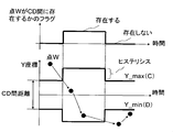
- FIG. 12 shows the hysteresis process replaced with the counter process for preventing the hunting of discrimination
- FIG. 1 is a side view showing an external appearance of an electric drive dump truck according to an embodiment of the present invention.
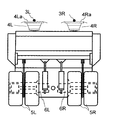
- a dump truck receives power from a vehicle body 1, a vessel 2 for loading earth and sand, and two left and right trolley wires 3L and 3R (one connected to high voltage and the other connected to ground). It consists of left and right current collectors 4L, 4R equipped with elevating sliding plates 4La, 4Ra, and left and right rear wheels (tires) 5L, 5R driven by the received power.
- the current collectors 4L and 4R are provided at the front portion of the vehicle main body 1.
- the dump truck is provided at the front portion of the vehicle body 1 and includes a trolley wire detection device 15 that continuously detects the front trolley wires 3L and 3R during traveling.
- the trolley wire detection device 15 is newly attached according to the present invention.
- the trolley wire detection device 15 is disposed in the front portion of the vehicle main body 1 in the illustrated example, it may be installed on the roof of the vehicle main body 1 or the like.
- FIG. 2 is a rear view showing the rear appearance of the dump truck.
- the rear wheels 5L and 5R have a double tire structure to withstand loads such as earth and sand loaded on the vessel 2. This double tire is braked by left and right electric motors (for example, induction motors) 6L and 6R.
- left and right electric motors for example, induction motors
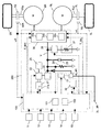
- FIG. 3 shows a drive system for an electrically driven dump truck according to the present embodiment.
- the drive system of the electric drive dump truck includes an accelerator pedal 11, a retard pedal 12, a shift lever 13, a combine sensor 14 that senses longitudinal acceleration, lateral acceleration, and yaw rate, an engine 21, an AC generator 22, and other engines.
- Load 28, rectifier circuit 23, detection resistor 24, capacitor 25, chopper circuit 26, grid resistor 27, current collectors 4L and 4R, rear wheels 5L and 5R, electric motors 6L and 6R, and outputs of electric motors 6L and 6R Reducers 7R and 7L connected to shafts 6La and 6Ra, electromagnetic pickup sensors 16R and 16L, and a control device 200 are provided.
- the control device 200 includes an inverter control device 30 that controls the electric motors 6L and 6R by inputting torque commands, and an elevator that raises and lowers the sliding plates 4La and 4Ra of the current collectors 4L and 4R by button operation of the driver or external input.
- the control device 31 includes a steering control device 32 that converts the steering operation of the driver into an electric signal to control the steering of the front wheels, a vehicle control device 50 that is a feature of the present invention, and a controller 100.
- the inverter control device 30 includes a known torque command calculation unit 30a, a motor control calculation unit 30b, and an inverter (switching element) 30c for each of the left and right electric motors 6L and 6R.
- the current collectors 4L and 4R are provided with a lifting device that lifts and lowers the scribing plates 4La and 4Ra by a lifting command signal from the lifting control device 31. Details of the current collectors 4L and 4R, the lifting control device 31, the steering system including the steering control device 32, and the vehicle control device 50 will be described later.
- the depression amount P of the accelerator pedal 11 and the depression amount Q of the retard pedal 12 are input to the controller 100, and are signals for controlling the magnitude of the driving force and the retarding force (braking force), respectively.
- the controller 100 outputs a command for the target rotational speed Nr to the engine 21.
- a table of the target engine speed Nr with respect to the accelerator opening is set in advance, and is output based on this table.
- the engine 21 is a diesel engine equipped with an electronic governor 21a. When the electronic governor 21a receives a command for the target speed Nr, the engine 21 controls the fuel injection amount so that the engine 21 rotates at the target speed Nr.
- the AC generator 22 is connected to the engine 21 and performs AC power generation.
- the electric power generated by the AC power generation is rectified by the rectifier circuit 23, stored in the capacitor 25, and the DC voltage value becomes V.
- the AC generator 22 is controlled by the controller 100 so that the voltage value obtained by dividing the DC voltage V by the detection resistor 24 is fed back and the voltage value becomes a predetermined constant voltage V0.
- the electric power generated by the AC generator 23 is supplied to the left and right electric motors 6L and 6R via the inverter control device 30.
- the controller 100 controls the AC generator 22 so that the electric power required for the electric motors 6L and 6R is supplied by controlling the AC generator 22 so that the DC voltage V rectified by the rectifier circuit 23 becomes a predetermined constant voltage V0. ing.
- the DC voltage V0 is directly supplied to the inverter control device 30 from the trolley wires 3L and 3R.
- the controller 100 calculates torque command values T_MR_a, T_ML_a corresponding to the operation amounts of the accelerator pedal 11 and the retard pedal 12, and the torque command values T_MR_a, T_ML_a and torque correction values T_MR_V, T_ML_V and yaw moment control for vehicle speed control.
- Torque command values T_MR, T_ML for the left and right electric motors 6L, 6R are generated and output based on the motor torque correction values T_ML_Y, T_MR_Y (described later).
- the torque command values T_MR, T_ML of the left and right electric motors 6L, 6R and the rotational speeds ⁇ R, ⁇ L of the electric motors 6L, 6R detected by the electromagnetic pickups 16R, 16L are input to the inverter control device 30, and the inverter control device 30 drives the electric motors 6L and 6R via a torque command calculation unit 30a, a motor control calculation unit 30b, and an inverter (switching element) 30c.
- the left and right rear wheels (tires) 5R and 5L are connected to the electric motors 6L and 6R via speed reducers 7R and 7L, respectively.
- the electromagnetic pickups 16R and 16L are sensors that detect the peripheral speed of one tooth of the gears in the speed reducers 7R and 7L. Further, for example, taking the right drive system as an example, a detection gear may be attached to the drive shaft inside the electric motor 6R or the drive shaft connecting the speed reducer 7R and the tire 5R and installed at that position.
- the controller 100 controls the AC generator 22 not to generate power. Further, the torque commands T_MR_a and T_ML_a from the controller 100 become negative, and the inverter control device 30 applies braking force to the dump truck that runs by driving the electric motors 6L and 6R. At this time, each of the electric motors 6L and 6R acts as a generator and functions to charge the capacitor 25 by a rectification function built in the inverter control device 30.
- the chopper circuit 26 operates so that the DC voltage value V is equal to or less than a preset DC voltage value V1, and current is passed through the grid resistor 27 to convert electrical energy into heat energy.
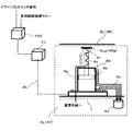
- FIG. 4 shows the configuration of current collectors 4L and 4R that receive power from trolley wires 3L and 3R.
- the current collectors 4L and 4R have the same configuration, and the configuration will be described by using the current collector 4L as a representative.
- the current collector 4L includes a hydraulic piston device 4a having a casing fixed to the vehicle main body 1 as an elevating device, and a sliding plate 4La is attached to the tip of the rod 4c of the hydraulic piston 4b of the hydraulic piston device 4a.
- the sliding plate 4La is controlled to contact and diverge from the trolley wire 3L by moving the hydraulic piston 4b up and down with oil sent from a hydraulic device 4e including a hydraulic pump via a hydraulic pipe 4d.
- the rod 4c of the hydraulic piston 4b and the sliding plate 4La are insulated by an insulator 4f.
- the electric power of the trolley wire 3L is connected to the power supply system of the inverter control device 30 for driving the motor shown in FIG. 3 via a sliding plate 4La and an electric wire 4g.
- the lift control device 31 sends a lift command signal 4h to the hydraulic equipment 4e based on a driver's lift switch operation, an external switch (flag) operation such as the vehicle control device 50 of the present invention, and a control command signal. It has become.
- the lifting / lowering device of the sliding plate 4La is constituted by the hydraulic piston device 4a, and the raising / lowering device is generally constituted by a system called a pantograph using a parallel link, a spring, a motor and the like as seen on a train. Also good.
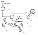
- the steering system includes the steering control device 32 and the steering device 40 described above.
- the steering device 40 includes a handle 41, a reaction force motor 42 with a steering angle sensor, a turning motor 43 with a turning angle sensor, and a rack and pinion gear 44.
- the steering angle sensor of the reaction force motor 42 with the steering angle sensor detects the operation amount of the handle 41, and transmits this to the steering control device 32.
- the steering control device 32 sends a torque signal to the turning motor 43 with the turning angle sensor so that the current turning angle becomes a turning angle corresponding to the steering angle of the driver, and the turning motor 43 with the turning angle sensor
- the front wheels 45L and 45R are steered via the rack and pinion gear 44 by the generated turning torque.
- the reaction force torque is transmitted to the reaction force motor with steering angle sensor 42 and the reaction force is transmitted to the handle 41.
- the steering control device 32 transmits the steering angle to the controller 100.
- the steering control device 32 also has a function of receiving the turning torque correction value from the controller 100 and operating the turning motor 43 with a turning angle sensor in accordance with this. Similarly, whether the steering control device 32 transmits a reaction force to the reaction force motor 42 with the steering angle sensor can be arbitrarily changed according to a mode at that time (described later) or a command from the controller 100. For example, the steering control device 32 receives a turning torque correction value from the controller 100 and operates the turning motor 43 with a turning angle sensor according to the correction value, while reacting to the reaction force motor with a steering angle sensor 42. If the force command value is not sent, the vehicle (dump truck) turns according to the steering angle, but the driver does not have a sense of steering at that time.
- the vehicle will not turn even if the handle 41 is turned.
- this means is effective when the controller 100 should not operate the handle 41 for some reason.
- the steering control device 32 generates torque in a direction opposite to the direction in which the driver 41 is steering. In general, some feel that the handle 41 is heavy, so that the driver can determine that the handle should not be operated in that direction.
- the steer-by-wire system in which the handle 41 is not directly connected to the front wheels 45L and 45R has been described.
- the present invention is not limited to this, and the reaction force motor with a steering angle sensor 42 and the turning motor 43 with a turning angle sensor are provided.
- An electric power steering system integrated and directly connected may be used.
- the turning motor 43 with a turning angle sensor may be a hydraulic servo type.
- the correction value sent from the controller 100 may be a correction angle instead of torque.
- the steering control device 32 may perform feedback control of torque so as to eliminate the deviation between the angle detected by the turning angle sensor and the correction angle.
- FIG. 6 is a block diagram showing functions for the steering control device 32 to calculate a turning torque command value.
- the steering control device 32 multiplies the steering angle of the driver received from the reaction force motor 42 with the steering angle sensor in the conversion unit 32a to convert it into the turning angle of the driver, and calculates the turning angle of the driver in the calculation unit 32b.
- the current turning angle is subtracted, and the conversion unit 32c multiplies the subtraction result by gain to convert it to the driver requested turning torque.
- the calculation unit 32d adds the steering torque correction value received from the controller 100 to the driver-requested steering torque to obtain a steering torque command value, and the steering torque command value is obtained as a steering motor with a steering angle sensor. Output to 43.
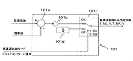
- FIG. 7 is a block diagram illustrating the function of the vehicle body speed control unit 101. As shown in FIG. 7, when the vehicle body speed control mode is On (1) (the switch unit 101c is On), the vehicle body speed control unit 101 inputs the target vehicle body speed and the current vehicle body speed and subtracts them in the calculation unit 101a.
- the conversion unit 101b multiplies the subtraction value by gain to convert it into torque, thereby obtaining and outputting torque correction values T_MR_V and T_ML_V for making the current vehicle speed the target vehicle body speed.
- the vehicle body speed control unit 101 inputs the rotational speeds ⁇ R and ⁇ L of the electric motors 6L and 6R detected by the electromagnetic pickups 16R and 16L, and calculates the vehicle body speed from the rotational speeds.
- the command for determining whether to enter the vehicle body speed control mode may be, for example, a switch provided in the vehicle control device 50, a switch operation from a driver, or an input from the outside.
- the vehicle body speed control mode can be canceled by the driver pressing the retard pedal or by an external input.
- the vehicle speed control mode command is set to Off (0) (the switch unit 101c is turned off), and the vehicle output control torque command value 0 is output from the zero output unit 101d.
- the controller 100 is preset with a table of engine speed command values corresponding to the torque correction values T_MR_V and T_ML_V, and outputs the engine speed command value to the engine 21 based on this table.
- the controller 100 includes a yaw moment control unit 102 for controlling the turning direction of the vehicle body.
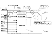
- FIG. 8 is a block diagram showing details of the function of the yaw moment control unit 102.
- a yaw moment control value generated by another yaw moment control such as a skid prevention control, a yaw moment correction value generated by the present invention, a vehicle body speed,
- the output signals are a steering torque correction value and torque correction values T_MR_Y and T_ML_Y for the motor.
- the yaw moment control value and the yaw moment correction value are added by the calculation unit 102a to become a yaw moment command value.
- the yaw moment command value is input to the steering torque control unit 102b, the motor torque control unit 102c, and the optimum distribution control unit 102d.
- the steering torque control unit 102b and the motor torque control unit 102c calculate a turning torque correction value and a motor torque correction value based on the input yaw moment command values, respectively.
- the optimum distribution control unit 102d calculates a yaw moment distribution ratio based on the input yaw moment command value, vehicle body speed, yaw rate, steering angle, longitudinal acceleration, and lateral acceleration, and a steering torque corresponding to the distribution ratio. A correction value and a motor torque correction value are calculated.
- the command of the yaw moment control mode is input to the switch unit 102e.
- the switch unit 102e outputs the turning torque correction value calculated by the steering torque control unit 102b when the yaw moment control mode is 1, and the motor torque control when the command is 2.
- the motor torque correction value calculated by the unit 102c is output. When the value is 3, the steering torque correction value calculated by the optimum distribution control unit 102d and the torque correction value for the left and right motors are output.
- FIG. 9 is a diagram showing the influence when the yaw moment correction value is realized by the driving force difference with respect to the total driving force when traveling with the motor driving force of 100%.
- the vehicle is traveling at a certain speed while the driving force is 100%.
- the total driving force of the vehicle is balanced with the running resistance (air resistance, friction resistance, inclination, etc.).
- 100% is the output limit of the motor of the rear wheel in the configuration of the present embodiment, and means the maximum value of the driving force of the motor that can be output at that speed.
- a yaw moment is generated by applying a braking / driving force to the vehicle.
- the actuator that should generate the yaw moment is desirably an operation with a relatively small reduction in speed even if it operates, and it is appropriate to set the yaw moment control mode to 1 as shown in FIG.
- the motor torque control yaw moment control mode 2
- the optimum distribution control yaw moment control mode 3
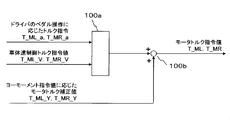
- FIG. 10 is a diagram illustrating an example of a method for calculating a motor torque command value.
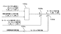
- one of the torque command values T_ML_a and T_MR_a corresponding to the driver's accelerator pedal / retard pedal operation and the torque command values T_ML_V and T_MR_V generated by the vehicle body speed control is selected by the processing unit 100a. For example, if there is a driver torque command, the driver torque command is selected by the processing unit 100a. Otherwise, the torque command for vehicle speed control is selected by the processing unit 100a.
- the motor torque correction values T_ML_Y and T_MR_Y corresponding to the yaw moment command values generated by the yaw moment control unit 102 are added to the torque command value selected by the processing unit 100a in the calculation unit 100b, and the motor torque command values T_ML, T_MR is calculated.
- this method of synthesizing the motor torque is merely an example, and various methods other than the method shown in the present embodiment, such as a known method, can be used.
- the drive system for the electrically driven dump truck includes the trolley wire detection device 15 that detects the trolley wires 3L and 3R and the vehicle control device 50.
- a sensor such as a laser radar, a millimeter wave radar, a camera or the like is typically considered.
- the present invention detects the relative positional relationship between the vehicle body and the trolley wire. It becomes means to do.
- a laser radar it is possible to detect the trolley line more accurately, preferably by searching along the X-axis direction of the vehicle body.
- millimeter wave radar the influence of weather such as fog and rain is smaller than other sensors.
- a radar sensor can detect not only the XY direction but also the Z-axis direction, which is the height of the vehicle body and the trolley line. Therefore, in the case where the system of the present invention is used in combination with another system that requires detection in the height direction, a radar sensor may be suitable.
- a camera since the trolley line is imaged from below the trolley line, a high contrast between the trolley line and the sky is obtained when the weather is good in the daytime, and the trolley line can be detected accurately.
- the illumination device 51 illuminates the trolley lines 3L and 3R to maintain the contrast of the trolley lines 3L and 3R with respect to the sky, and there is a high contrast between the trolley lines 3L and 3R and the sky such as evening, night, and rain. Even if it is difficult to obtain, the trolley wire can be detected accurately.
- a system may be constructed by combining any two or more sensors.
- FIG. 11 is a diagram showing the configuration of the vehicle control device 50 and the input / output relationship between the vehicle control device 50 and the controller 100.
- the vehicle control device 50 processes the information detected by the trolley wire detection device 15 to acquire information related to the relative positional relationship between the vehicle body and the trolley wire, and the trolley wire detection information processing unit 50 a
- the vehicle state quantity calculation unit 50b calculates the vehicle state quantity based on the information obtained by the line detection information processing part 50a, and the vehicle state quantity control unit 50c controls the vehicle state quantity based on the result.
- the trolley wires 3 ⁇ / b> L and 3 ⁇ / b> R are supported by the support column 53 via the insulator 52. Further, the vehicle control device 50 outputs a target speed correction value, a yaw moment correction value, a yaw moment control mode, a lift control device lift command, control / detection state information, and the like.
- the trolley line detection device 15 is a camera
- the trolley line detection information processing unit 50 a is an image information processing unit that processes image information captured by the camera 15.
- the camera 15 images the trolley lines 3L and 3R.
- the left and right trolley lines 3L and 3R may be imaged by one camera.
- Image information captured by the camera 15 is sent to the image information processing unit 50 a of the vehicle control device 50.
- the image information is a pixel array in a range captured by the camera 15, and the image information processing unit 50a converts the image information into necessary information.
- the image sent to the image information processing unit 50a may be blurred whitely called halation, and the target to be detected may not be recognized.
- halation whitely
- the target to be detected may not be recognized.
- the camera 15 there are two places where the camera 15 is installed: a camera that images the trolley lines 3L and 3R in front of the vehicle and a camera that images the trolley lines 3L and 3R in the rear of the vehicle, and one of them is image information.
- a method of correcting by the other camera is also conceivable.
- the method for detecting halation depends on a known method.
- the correction can also be made by the other camera.
- the trolley wires 3L and 3R are imaged through the glass, and the image information processing unit 50a can determine that the glass has deteriorated the visibility due to dust or mud, a wiper or washer liquid You may wash
- the image information processing unit 50a determines that there is not enough light to detect the trolley lines 3L and 3R at dusk or darkness, the image information processing unit 50a issues a blinking instruction to the lighting device 51.
- the contrast of the trolley lines 3L and 3R with respect to the sky may be maintained by illuminating and illuminating the trolley lines 3L and 3R.
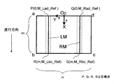
- FIG. 14 is a diagram showing an image acquired by the camera 15 in that case.
- the camera 15 images the trolley lines 3L and 3R as seen from below, the imaging areas a, b, c, and d of the image when the trolley lines 3L and 3R illustrated in FIG.
- the front-rear relationship positional relationship between ad and bc in the vertical direction in the figure
- the traveling direction of the vehicle appear in reverse.
- trolley lines 3 ⁇ / b> L and 3 ⁇ / b> R appear vertically to the screen in parallel with the traveling direction.
- processing for extracting edge portions is performed. Accordingly, the left trolley line 3L is divided into an edge LL and an edge LR portion, and the right trolley line 3R is divided into an edge RL and an edge RR portion.
- the center lines of the respective edges of the left and right trolley lines 3L and 3R are obtained.
- a coordinate system (the Y axis is the da direction and the X axis is the ab direction) with respect to the number of pixels whose origin is Oc at the upper center of the screen is taken.
- Oc the origin
- the intersection S of RM with bc Take (m, M_Rbc_Ref).
- the points P, Q, R, and S are points located on the trolley lines 3L and 3R, and these are defined as target points.
- M represents the number of pixels in the vertical direction
- n represents the number of pixels in the horizontal direction.
- the left and right sides are located when the trolley wires 3L and 3R are positioned at the center of the sliding plates 4La and 4Ra. It is robust against shifts due to vehicle misalignment and vehicle shake. Therefore, it is desirable for the vehicle to travel in such a state.
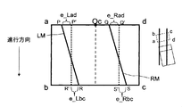
- FIG. 17 shows a case where the vehicle has shifted to the left. If the representative point of the vehicle body 1 is set at the intersection of a straight line (straight line in the traveling direction of the vehicle body 1) passing through the center of the sliding plates 4La and 4Ra and the ad and bc of the imaging region, the representative point is 17 points P ′, Q ′, R ′, and S ′.
- This representative point is a point used to control the position of the vehicle with respect to the trolley lines 3L and 3R. Therefore, it can be said that the representative points P ′, Q ′, R ′, and S ′ are control points.
- the coordinates of each representative point are defined as M_Lad_Cont, M_Rad_Cont, M_Lbc_Cont, and M_Rbc_Cont.
- FIG. 18 shows a case where the vehicle is traveling obliquely with respect to the trolley lines 3L and 3R. Also in this case, the representative points are point P ′, point Q ′, point R ′, and point S ′.
- the image information processing unit 50a sends these coordinate information to the vehicle state quantity calculation unit 50b.
- the vehicle state quantity calculation unit 50b calculates a deviation between the representative points P ′, Q ′, R ′, S ′ and the target points P, Q, R, S.
- the deviation between the representative point and the target point is e_Lad, e_Rad, e_Lbc, and e_Rbc, these are calculated as follows.
- e_Lad M_Lad_Ref ⁇ M_Lad_Cont (1)
- e_Rad M_Rad_Ref ⁇ M_Rad_Cont (2)
- e_Lbc M_Lbc_Ref ⁇ M_Lbc_Cont (3)
- e_Rbc M_Rbc_Ref ⁇ M_Rbc_Cont (4)
- the vehicle inclination e ⁇ _L with respect to the left trolley line 3L and the vehicle inclination e ⁇ _R with respect to the right trolley line 3R can be calculated as follows.
- e ⁇ _L (e_Lbc ⁇ e_Lad) / m (5)
- e ⁇ _R (e_Rbc ⁇ e_Rad) / m (6)
- the equations (2), (4), and (5) are compared with the equations (1), (3), and (5).
- Equation (6) is redundant. Therefore, preferably, when either one cannot calculate the deviation amount or the inclination for some reason, the calculation is performed using the information on which the calculation is possible.
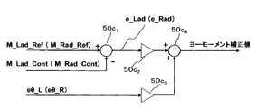
- FIG. 19 shows a process in which a gain is applied to the deviation amount and the inclination represented by the equation (1) to obtain a yaw moment correction value.
- FIG. 19 is a block diagram illustrating details of the function of the vehicle state quantity control unit 50c.
- the target point is P or Q
- the representative point is P ′ or Q ′.
- the vehicle state quantity calculating section 50b the representative point P from the coordinate values M_Lad_Ref (M_Rad_Ref) of the target point P input from the vehicle state quantity calculating unit 50b in the arithmetic unit 50c 1 (Q) '(Q ' ) Is subtracted from the coordinate value M_Lad_Cont (M_Rad_Cont) to obtain a deviation e_Lad (e_Rad) between the representative point P ′ (Q ′) and the target point P (Q).
- Vehicle state quantity control unit 50c converts over gain deviation e_Lad (e_Rad) in the conversion unit 50c 2 values of the deviation in yaw moment amount.
- converting unit 50c 3 converts the yaw moment amount by multiplying the gain tilt of the vehicle inputted from the vehicle state quantity calculating unit 50b e ⁇ _L (e ⁇ _R). These two yaw moment amounts are added in the calculation unit 50 c 4 to obtain a yaw moment correction value, and this yaw moment correction value is output to the yaw moment control unit 102.
- the vehicle state quantity control unit 50c determines the yaw moment control mode described with reference to FIG.
- the aforementioned yaw moment control unit 102 of the controller 100 calculates the motor torque command value and the turning torque correction value based on the yaw moment correction value and the yaw moment control mode determined by the vehicle state quantity control unit 50c. And output to the inverter control device 30 and the steering control device 32, respectively.
- the control device constituted by the vehicle control device 50, the controller 100, the inverter control device 30, and the steering control device 32 allows the vehicle main body 1 to travel following the trolley lines 3L and 3R.
- the control for giving the yaw moment is performed (claim 1).
- the control device performs control to give the vehicle body 1 a yaw moment so that the representative point P ′ (Q ′) approaches the target point P (Q).
- the control device performs control to give the yaw moment to the vehicle main body 1 so that the inclination e ⁇ _L becomes small.
- the illumination device 51 illuminates the trolley lines 3L and 3R, so that the contrast of the trolley lines 3L and 3R with respect to the sky is maintained, and the daytime weather condition is good.
- the illumination device 51 illuminates the trolley lines 3L and 3R, so that the contrast of the trolley lines 3L and 3R with respect to the sky is maintained, and the daytime weather condition is good.
- it is difficult to obtain a high contrast between the trolley lines 3L and 3R and the sky such as in the evening, at night, and in the rain, it is possible to accurately control the yaw moment that travels following the trolley lines 3L and 3R.
- control device 200 performs the yaw moment control with the vehicle control device 50 and the controller 100 as separate bodies, so that even if the controller 100 is an existing controller, it is only necessary to add the vehicle control device 50 to the yaw of the present invention.
- the control system can be made flexible, for example, the moment control can be performed, or the parameters of the yaw moment control can be adjusted only by changing the function of the vehicle control device 50.
- the previous embodiment is a control that applies a yaw moment to the vehicle body 1 so that the vehicle body 1 travels following the trolley lines 3L and 3R (
- the lift control of the sliding plates 4La or 4Ra of the current collectors 4L and 4R is further performed and the trolley line tracking control is performed.
- a dead zone is provided in the deviation between the representative point and the target point, and the trolley line follow-up control is performed only when the deviation exceeds the dead zone.
- Image information processing unit 50a The processing content of the image information processing unit 50a is the same as that of the previous embodiment, and the image information processing unit 50a sends the coordinate information of the representative points P ′, Q ′, R ′, S ′ to the vehicle state quantity calculation unit 50b. .
- the vehicle state quantity calculation unit 50b is a control amount or command such as a yaw moment correction value for performing trolley line follow-up control, a lift control device lift command for performing sliding plate lift control, a yaw moment control mode, a target speed correction value, or the like.
- the vehicle state quantity for generating the value is calculated, and the vehicle state quantity control unit 50c controls the control quantity such as the yaw moment correction value, the lift control device lift command, the yaw moment control mode, and the target speed correction value based on the calculation result.
- a command value is generated and output.
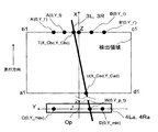
- FIG. 20 is a diagram showing a trolley line detection region and a coordinate system used in the present embodiment.
- the vehicle state quantity calculation unit 50b obtains a1, b1, c1, in FIG. 20 from the image information of the imaging areas a, b, c, d as shown in FIGS. 16 to 18 acquired by the camera 15 in the image information processing unit 50a.
- a region as indicated by d1 is cut out and acquired as a trolley line detection region.
- the sides a1 and d1 correspond to a part of the sides a and d of the imaging regions a, b, c, and d shown in FIGS. 16 to 18, and the sides b1 and c1 are the imaging regions a, b, c, and d. It corresponds to a part of sides b and c.
- the trolley line detection areas a1, b1, c1, and d1 indicate the positional relationship between the sliding board and the trolley line when the trolley line 3L or 3R is viewed from above, and the vehicle passes through the left and right centers of the sliding board 4La or 4Ra.
- a straight line extending in the traveling direction is a region passing through the center of the sides a1 and d1 and the center of the sides b1 and c1.
- the image information of the imaging areas a, b, c, and d acquired by the camera 15 is image information obtained by imaging the trolley lines 3L and 3R from below, and is obtained when the trolley lines 3L and 3R are viewed from above.
- the trolley line detection areas a1, b1, c1, and d1 appear in reverse relation to the imaging areas a, b, c, and d (vertical direction in the drawing).
- the vehicle state quantity calculation unit 50b sets a coordinate system in which the center of the sliding plate 4La or 4Ra is the origin Op, the traveling direction is the X axis, and the traveling direction left is the Y axis, and the X axis and the side b1-c1 are set.
- a representative point is set at the intersection point Z, and two target points are set at the intersection point T between the trolley line 3L or 3R and the side b1-c1 and the intersection point U between the trolley line 3L or 3R and the side a1-d1.
- the camera 15 and the sliding plates 4La or 4Ra of the current collectors 4L and 4R are both attached to the vehicle body and the positional relationship between them is known, the coordinates with the Oc point shown in FIGS.
- the coordinates of the intersections Z, T, and U can be easily obtained by converting the values of the points P ′, P, and R in the system to the values of the coordinate system having the origin of the Op point in FIG.
- the vehicle state quantity calculation unit 50b calculates a deviation between the representative point Z and the target point T.
- the vehicle state quantity calculation unit 50b sets the Y coordinate value Y_Cbc of the target point T.
- the deviation between the representative point Z and the target point T is assumed.
- the deviation Y_Cbc is positive when the vehicle is shifted to the right with respect to the trolley line, and is negative when the vehicle is shifted to the left.
- the vehicle inclination ⁇ _t with respect to the trolley line 3L or 3R at a certain time t is expressed by the following equation using the coordinate values of the two target points T and U.
- ⁇ _t (Y_Cbc ⁇ Y_Cad) / (X_Cbc ⁇ X_Cad) (7)
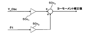
- the vehicle state quantity control unit 50c calculates a yaw moment correction value for making the representative point Z coincide with the target point T using the deviation Y_Cbc between the representative point Z and the target point T or the vehicle inclination ⁇ _t.
- FIG. 23B shows a process for calculating the yaw moment correction value using the deviation Y_Cbc or the gradient ⁇ _t.
- FIG. 23B is a block diagram similar to FIG. 19 illustrating an example of a method for calculating the yaw moment correction value.
- Y coordinate values Y_Cbc the target point T in front of the sliding plate 4La or 4Ra is equal to the deviation of the representative point Z and the target point T
- the deviation Y_Cbc is computed by the computing section 50c 1 of FIG. 19 This corresponds to the deviation e_Lad between the representative point P ′ and the target point P.
- the arithmetic unit 50c 1 is not provided.
- Vehicle state quantity control unit 50c converts over gain deviation Y_Cbc in the conversion unit 50c 2 deviations Y_Cbc the yaw moment amount.
- converting unit 50c 3 converts the yaw moment amount by multiplying the gain to tilt Shita_t. These two yaw moment amounts are added in the calculation unit 50 c 4 to obtain a yaw moment correction value, and this yaw moment correction value is output to the yaw moment control unit 102.
- the vehicle state quantity calculation unit 50b calculates the vehicle inclination ⁇ _t at a certain time t. This inclination ⁇ _t can be calculated by the above equation (7) using the coordinate values of the two target points T and U shown in FIG. 20 as described above.
- the vehicle state quantity calculation unit 50b calculates the Y coordinate Y_p_t of the point W.
- the value Y_p_t + 1 after one step of Y_p_t (after time ⁇ ) is expressed as follows using the vehicle speed V.
- Y_p_t + 1 Y_p_t + V ⁇ tan ⁇ _t (9)
- Y_min Y_min ( If the Y coordinate of the point D) ⁇ Y_p_t ⁇ Y_max (the Y coordinate of the point C), it can be said that the sliding plates 4La and 4Ra can be raised in the region where Y_min ⁇ Y_p_t + 1 ⁇ Y_max.
- the vehicle state quantity calculation unit 50b determines that the Y coordinate Y_p_t of the point W is out of the range of Y_min (Y coordinate of the point D) and Y_max (Y coordinate of the point C) at the next control step t + 1 at the current time t. And the determination result is output to the vehicle state quantity control unit 50c.
- the vehicle state quantity control unit 50c lowers or slides the sliding plates 4La and 4Ra. A command signal for prohibiting raising of the plates 4La and 4Ra is output.
- a command signal for allowing the sliding plates 4La and 4Ra to be raised or to raise the sliding plates 4La and 4Ra is output.
- the vehicle state quantity control unit 50c may apply a reaction force correction to the reaction force motor 42 (FIG. 5) of the steering device 40 in accordance with the position of Y_p_t.
- This correction amount may be, for example, a small reaction force in a region where Y_min ⁇ Y_p_t + 1 ⁇ Y_max, and a large reaction force in a region where Y_min ⁇ Y_p_t + 1 or Y_p_t + 1 ⁇ Y_max.
- the vehicle control device 50 performs both the trolley wire follow-up control and the sliding plate lifting control.
- the vehicle state quantity control unit 50c outputs a yaw moment correction value obtained by multiplying the deviation Y_Cbc and the inclination ⁇ _t by a gain. Since the yaw moment correction value is output until the deviation Y_Cbc and the inclination ⁇ _t become zero, the Y coordinate Y_p_t of the point W on the sliding plate 4La or 4Ra and the inclination ⁇ _t of the vehicle tend to converge to zero.
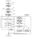
- FIG. 21 is a flowchart showing the flow of processing from when the upper image is captured by the camera until control output is performed.
- the camera is installed in front of the vehicle body 1 on the extension line of the axle as shown in FIG. 12, and the number of trolley lines to be imaged is one.
- FIG. 22 is a view similar to FIG. 20 in which a dead zone for trolley line tracking control is set.
- the target points T and U and the representative point Z are set for the detection areas a1, b1, c1, and d1.
- points A and B that define a dead zone for the trolley line tracking control are set at positions separated from the representative point Z by predetermined distances Y_l and Y_r (first threshold values).
- step 200 the image information processing unit 50a images the upper portion of the vehicle body 1 with a camera.
- the trolley line 3L or 3R is searched from the image captured in step 201.
- searching in step 201 if the trolley line 3L or 3R is detected for the first time, the search is performed from the entire area of the imaging screen. However, once the trolley line 3L or 3R is detected, it is not necessary to search from the entire area again. Searching the vicinity of the coordinates of the trolley line 3L or 3R that has been performed is effective because it shortens the search time.
- step 202 it is determined whether there is an equivalent to the trolley line 3L or 3R in the imaging screen. If there is no equivalent to the trolley line 3L or 3R, the process is terminated. If there is something corresponding to the trolley line 3L or 3R, the image information processing unit 50a performs image processing for extracting an edge in step 203A and calculating the middle line of the trolley line 3L or 3R.
- step 203B the vehicle state quantity calculation unit 50b sets the target points T and U described above, and calculates their coordinates.
- the processing using the coordinate information of the target points T and U is divided into two systems, a follow-up control step 300 for the trolley lines 3L and 3R and a lift control step 400 for the sliding plates 4La and 4Ra.
- step 310 the vehicle state quantity calculation unit 50b determines that the target point T is between the point A and the point B set at a position separated by a predetermined distance (Y_l, Y_r) from the representative point Z shown in FIG. It is determined whether or not (Y_l ⁇ Y_Cbc, Y_r ⁇ Y_Cbc).
- the process proceeds to step 320, and the vehicle state quantity control unit 50c calculates and outputs the yaw moment correction value.
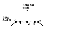
- FIG. 23A is a diagram showing an example of a method for calculating the yaw moment correction value at that time.
- the slope of the characteristic line outside points A and B in FIG. 23A corresponds to the gain of the conversion unit 50c 2 in FIG. 23B (the conversion unit 50c 2 in FIG. 19).
- the yaw moment correction value corresponding to the Y coordinate value Y_Cbc (the deviation between the representative point Z and the target point T) of the target point T is calculated outside the points A and B. That is, outside the point A (Y_Cbc value is positive), the yaw moment correction value is increased as Y_Cbc increases. Outside the point B (Y_Cbc value is negative), the yaw moment correction value is decreased as Y_Cbc decreases.
- the yaw moment correction value When the yaw moment correction value reaches the maximum correction value or the minimum correction value, the yaw moment correction value is constant in order to prevent sudden turning.
- a constant yaw moment correction value may be output.
- the operation frequency of the electric motors 6L and 6R for the rear wheels is reduced, and the stability of control and a comfortable riding comfort can be ensured.
- the range of the point AB that does not require the yaw moment correction may be determined according to the width of the sliding plate 4La or 4Ra.
- the sliding plates 4La, 4Ra are moved laterally from the trolley wires 3L, 3R during traveling.
- the vehicle main body 1 quickly returns to the center of the sliding plates 4La and 4Ra, so that the dump truck can be reliably prevented from coming off from the travel path of the trolley lines 3L and 3R. .
- step 330 the yaw moment control mode is selected and output.
- “1” is selected as the yaw moment control mode.
- FIG. 24 is a view similar to FIGS. 20 and 22 in which departure monitoring points for trolley line tracking control are set.
- FIG. 25 is a flowchart showing step 300 ′ in place of the trolley line follow-up control step 300 in the flowchart shown in FIG. 21.
- a point A ′ (second threshold value), a point at the position of the Y coordinate value Y_l ′ outside the point A (the Y coordinate large side)
- a point B ′ (second threshold value) is set at the position of the Y coordinate value Y_r ′ outside B (the side where the negative value of the Y coordinate is small).
- step 320 for calculating the yaw moment correction value is the same as that of FIG. 21 described above.
- step 321 it is determined in step 321 whether the position of the target point T is further between the point A ′ and the point B ′ (Y_l ′ ⁇ Y_Cbc, Y_r ′ ⁇ Y_Cbc), If true, the vehicle may deviate from the trolley travel path, so the driver is warned by voice and / or display to perform corrective steering in step 322 (Claim 6).
- FIG. 26 is a diagram showing an example of a method for calculating the target vehicle speed correction value at that time.
- the target vehicle speed correction value is set so as to reduce the target vehicle speed according to the degree of deviation from the points A ′ and B ′. Is calculated. That is, outside the point A ′ (Y_Cbc value is positive), the correction value on the decrease side of the target vehicle speed is increased as Y_Cbc increases. Outside the point B ′ (Y_Cbc value is negative), the correction value on the decrease side of the target vehicle speed is decreased as Y_Cbc decreases.
- FIG. 27 is a diagram showing another example of a method for calculating a target vehicle speed correction value.
- the target vehicle speed may be corrected to increase as the target point T approaches the representative point Z. That is, inside the point A ′ (Y_Cbc value is positive), the correction value on the increase side of the target vehicle speed is increased as Y_Cbc decreases. Inside the point B ′ (Y_Cbc value is negative), the correction value on the increase side of the target vehicle speed is decreased as Y_Cbc increases.
- the traveling speed is controlled to increase as the absolute value of the deviation Y_Cbc decreases. Increasing the vehicle speed in this way has the effect of improving work efficiency.
- FIG. 28 is a view similar to FIG. 10, showing a motor torque generation method based on a target vehicle speed correction value.
- the correction value of the target vehicle speed calculated as described above is converted into a motor torque command value by applying a gain in the conversion unit 100c.
- a motor torque command value calculated by the calculation unit 100b (a torque command in which the motor torque correction values T_ML_Y and T_MR_Y corresponding to the yaw moment command value generated by the yaw moment control unit 102 (FIG. 8) are selected by the processing unit 100a is used.
- the motor torque command value corresponding to the correction value of the target vehicle speed calculated by the conversion unit 100c is added to the value added to the value) to calculate the motor torque command values T_ML and T_MR.
- the Y coordinate Y_p_t of the point W on the sliding plate 4La or 4Ra where the sliding plate 4La or 4Ra is in contact with the trolley wire 3L or 3R and good power can be continuously obtained.
- Point C and point D are set as the range of.
- step 410 of FIG. 21 the inclination of the trolley line 3L or 3R is calculated from the target points T and U according to the equation (7). From the inclination and the coordinates of the target point T, in step 420, the coordinates of the intersection W of the sliding plate 4La or 4Ra and the trolley line 3L or 3R are calculated. This is calculated according to equation (8). Next, in step 430, an estimated value Y_p_t + 1 in the next step of the Y coordinate of the intersection W is calculated.
- step 440 the duration of the state in which the estimated value is within a predetermined range between point C and point D (Y_min ⁇ Y_p_t + 1 ⁇ Y_max) is measured by a counter, and the state is, for example, 1 second. It is determined whether or not it has continued.
- step 440 when the state where the point W is between the point C and the point D continues for one second or more, the process proceeds to step 450, and the sliding plates 4La and 4Ra are allowed to be raised. At this time, for example, the driver may be notified by voice and / or display that the sliding plates 4La and 4Ra may be raised.
- the vehicle control device 50 When the driver performs a switch operation, the vehicle control device 50 outputs a command signal for ascending control, and the elevating control device 31 performs ascending control of the sliding plates 4La and 4Ra based on the command signal.
- the sliding plates 4La and 4Ra when the sliding plates 4La and 4Ra are lowered, the sliding plates 4La and 4Ra may be automatically raised instead of entrusting the driver to raise and lower.
- the vehicle control device 50 outputs a command signal for raising control, and the lifting control device 31 raises and controls the sliding plates 4La and 4Ra based on the command signal.
- the driver may be notified by voice and / or display that the sliding plates 4La and 4Ra are automatically raised.
- step 460 if the state in the predetermined range in step 440 is less than 1 second, the process proceeds to step 460, and if the slabs 4La and 4Ra are raised, the driver is instructed by voice or display to lower. . It may also be lowered automatically. At this time, for example, it is preferable to inform the driver by voice and / or display that the sliding plates 4La and 4Ra are automatically lowered. Further, if the sliding plates 4La and 4Ra are in a lowered state, it is prohibited to raise the sliding plates 4La and 4Ra. At this time, it is preferable to inform the driver by voice and / or display that raising of the sliding plates 4La and 4Ra is prohibited.
- the vehicle control device 50 outputs a command signal by the driver's switch operation or automatically, and the lift control device 31 controls the sliding plates 4La and 4Ra to descend based on the command signal.
- the lift control device 31 controls the sliding plates 4La and 4Ra to descend based on the command signal.
- step 440 in FIG. 21 it is determined whether the estimated value Y_p_t + 1 is between point C and point D (Y_min ⁇ Y_p_t + 1 ⁇ Y_max), for example, for one second or longer.
- the processing immediately proceeds to step 450, and the estimated value Y_p_t + 1 is between the point C and the point D (Y_min ⁇ Y_p_t + 1 ⁇ Y_max). If not, the process may immediately proceed to step 450.
- the processing of step 440 is intended to prevent discrimination hunting by repeatedly exceeding or falling within a predetermined range when Y_p_t is not stable due to bumps on the road surface or noise in image processing. It is valid.
- FIG. 29 is a diagram showing a hysteresis process instead of the process using the counter in step 440.
- the setting of the point C and the point D is changed so as to increase the distance between the point C and the point D.
- the setting of the point C and the point D is changed so as to reduce the distance between the point C and the point D.
Landscapes
- Engineering & Computer Science (AREA)
- Power Engineering (AREA)
- Transportation (AREA)
- Mechanical Engineering (AREA)
- Life Sciences & Earth Sciences (AREA)
- Sustainable Development (AREA)
- Sustainable Energy (AREA)
- Electric Propulsion And Braking For Vehicles (AREA)
- Current-Collector Devices For Electrically Propelled Vehicles (AREA)
- Steering Control In Accordance With Driving Conditions (AREA)
- Traffic Control Systems (AREA)
- Control Of Driving Devices And Active Controlling Of Vehicle (AREA)
Abstract
Description
(車両-ダンプトラック-の構成に関して)
図1は、本発明の一実施の形態による電気駆動ダンプトラックの側部外観を示す側面図である。
アクセルペダル11の踏込み量Pとリタードペダル12の踏込み量Qはコントローラ100の入力となり、それぞれ駆動力やリタード力(ブレーキ力)の大きさを制御する信号となる。例えばドライバがアクセルペダル11を踏み込んでダンプトラックを前進又は後進させるときは、コントローラ100からエンジン21に対して目標回転数Nrの指令を出力する。これはアクセル開度に対する目標エンジン回転数Nrのテーブルが予め設定されており、これに基づいて出力される。エンジン21は電子ガバナ21aを装着したディーゼルエンジンであり、電子ガバナ21aは目標回転数Nrの指令を受け取ると、エンジン21が目標回転数Nrで回転するように燃料噴射量を制御する。
次に、集電装置4L,4Rのすり板4La,4Raの昇降装置について説明する。図4にトロリー線3L,3Rから電力を受ける集電装置4L,4Rの構成を示す。集電装置4L,4Rは同じ構成を有しており、その構成を集電装置4Lで代表して説明する。集電装置4Lは、昇降装置として車両本体1に筐体を固定した油圧ピストン装置4aを備え、油圧ピストン装置4aの油圧ピストン4bのロッド4cの先端にすり板4Laが取り付けられている。このすり板4Laは、油圧配管4dを介して油圧ポンプを含む油圧機器4eから送られた油で油圧ピストン4bを上下させることで、トロリー線3Lとの接触、乖離を制御される。油圧ピストン4bのロッド4cとすり板4Laは絶縁体4fによって絶縁されている。トロリー線3Lの電力はすり板4La、電線4gを介して、図3に示したモータ駆動のためのインバータ制御装置30の電源系統へ接続されている。昇降制御装置31は、ドライバの昇降スイッチ操作や本発明の車両制御装置50などの外部からのスイッチ(フラグ)操作や制御の指令信号に基づいて、油圧機器4eに昇降指令信号4hを送る仕組みとなっている。当然、油圧ピストン装置4aによりすり板4Laの昇降装置を構成する他に、一般的には電車で見られるような平行リンク、ばね、モータ等を利用したパンタグラフと呼ばれるシステムで昇降装置を構成してもよい。
次に図5を用いて操舵システムについて説明する。
図3に戻り、コントローラ100は、車体速制御モードが選択された場合に、車体速制御モードで設定される目標車体速に対する現在の車体速のフィードバック制御を行い、車体速制御モードにて車体速を制御することを可能とする車体速制御部101を備えている。図7は車体速制御部101の機能の説明を示すブロック図である。図7に示すように、車体速制御部101は、車体速制御モードがOn(1)(スイッチ部101cがOn)のとき、目標車体速と現在の車体速を入力して演算部101aにおいて減算し、変換部101bにおいてその減算値にゲインをかけてトルクに変換することで現車速を目標車体速にするためのトルク補正値T_MR_V,T_ML_Vを求めて出力する。車体速制御部101は、電磁ピックアップ16R,16Lにより検出される各電動モータ6L,6Rの回転速度ωR,ωLを入力し、この回転速度から車体速を演算する。車体速制御モードに入るか否かの指令は、例えば車両制御装置50にスイッチを設け、ドライバからのスイッチ操作でも良いし、外部からの入力によってなされるものでも良い。車体速制御モードの解除は、ドライバがリタードペダルを踏むことで行ってもよいし、外部からの入力によって行ってもよい。車体速制御モードを解除した場合、車体速制御モードの指令をOff(0)(スイッチ部101cをOff)とし、ゼロ出力部101dから車体制御トルク指令値0を出力する。またコントローラ100は、トルク補正値T_MR_V,T_ML_Vに応じたエンジン回転数指令値のテーブルがあらかじめ設定されており、このテーブルに基づいてエンジン回転数指令値をエンジン21に対して出力する。
さらに、コントローラ100は、図3に示すように、車体の旋回方向を制御するためのヨーモーメント制御部102を備えている。図8はヨーモーメント制御部102の機能の詳細を示すブロック図である。図8に示すように、ヨーモーメント制御部102に対する入力信号として、例えば横滑り防止制御といった他のヨーモーメント制御によって生成されるヨーモーメント制御値、本発明によって生成されるヨーモーメント補正値、車体速、前後加速度、横加速度、ヨーレイト、操舵角、ヨーモーメント制御モードの指令がある。出力信号は転舵トルク補正値とモータへのトルク補正値T_MR_Y,T_ML_Yである。ヨーモーメント制御値とヨーモーメント補正値は演算部102aにおいて加算され、ヨーモーメント指令値となる。このヨーモーメント指令値は操舵トルク制御部102b、モータトルク制御部102c、最適配分制御部102dに入力される。操舵トルク制御部102b及びモータトルク制御部102cは、それぞれ入力されたヨーモーメント指令値に基づいて転舵トルク補正値とモータトルク補正値を算出する。また、最適配分制御部102dは入力されたヨーモーメント指令値、車体速、ヨーレイト、操舵角、前後加速度、横加速度に基づいてヨーモーメントの配分比を計算し、その配分比に応じた転舵トルク補正値とモータトルク補正値を算出する。ヨーモーメント制御モードの指令はスイッチ部102eに入力され、スイッチ部102eは、ヨーモーメント制御モードが1のときには操舵トルク制御部102bで演算した転舵トルク補正値を出力し、2のときにはモータトルク制御部102cで演算したモータトルク補正値を出力し、3のときには最適配分制御部102dで演算した操舵トルク補正値と左右モータへのトルク補正値を出力する。
ところで、ダンプが走行する鉱山では土砂等を運ぶ時間の短縮の要求が高い。かかる時間が短ければそれだけ一台当りの土砂を運ぶインターバルが短くなり、回数をこなせるからである。時間短縮に直接影響するのは車両速度であり、従って、車両速度が低くなるような制御を行うことは避けることが望ましい。
コントローラ100におけるモータトルク指令の算出方法に関して図10を用いて説明する。図10はモータトルク指令値の算出方法の一例を示す図である。まず、前述のとおりドライバのアクセルペダル・リタードペダル操作に応じたトルク指令値T_ML_a,T_MR_aと車体速制御によって生成されたトルク指令値T_ML_V,T_MR_Vの一方を処理部100aで選択する。例えば、ドライバのトルク指令が有る場合はドライバのトルク指令、それ以外は車体速制御のトルク指令を処理部100aで選択する。その後、処理部100aで選択したトルク指令値に、ヨーモーメント制御部102によって生成されたヨーモーメント指令値に応じたモータトルク補正値T_ML_Y,T_MR_Yを演算部100bにおいて加算し、モータトルク指令値T_ML,T_MRを算出する。なお、このモータトルクの合成方法は一例であり、公知の手法など、本実施の形態に示した手法以外の様々な手法を用いることができる。
次に、本実施の形態の電気駆動ダンプトラックの特徴部の全体構成を図11を用いて説明する。
カメラの場合、トロリー線の下方からトロリー線を撮像するため、昼間で天候の良いときはトロリー線と空との高いコントラストが得られ、トロリー線を正確に検出することができる。また、車両本体1にトロリー線3L,3Rを照らす照明装置51を設けてもよい(請求項9)。この場合は、照明装置51でトロリー線3L,3Rを照らすことで、空に対するトロリー線3L,3Rのコントラストが維持され、夕方、夜間、雨天など、トロリー線3L,3Rと空との高いコントラストが得にくい場合でも、トロリー線を正確に検出することができる。
カメラ15はトロリー線3L,3Rを撮像する。この二本のトロリー線3L,3Rをカメラ一台で撮像する場合は、カメラ15を左右のトロリー線3L,3Rの中央に配置することが好ましい。カメラ15の構成としては、左右のトロリー線3L,3Rをそれぞれ一台のカメラで撮像してもよい。カメラ15により撮像された画像情報は、車両制御装置50の画像情報処理部50aに送られる。画像情報は、カメラ15が撮像した範囲のピクセル配列であり、画像情報処理部50aはその画像情報を必要な情報に変換する。
車両状態量算出部50bは、代表点P’,Q’,R’,S’と目標点P,Q,R,Sとの偏差を算出する。ここで、代表点と目標点との偏差をそれぞれe_Lad、e_Rad、e_Lbc、e_Rbcとすると、これらは以下のように計算する。
e_Lad=M_Lad_Ref-M_Lad_Cont ・・・(1)
e_Rad=M_Rad_Ref-M_Rad_Cont ・・・(2)
e_Lbc=M_Lbc_Ref-M_Lbc_Cont ・・・(3)
e_Rbc=M_Rbc_Ref-M_Rbc_Cont ・・・(4)
これらの偏差は、車両がトロリー線に対して左にずれた場合に正、右にずれた場合に負となる。
eθ_L= (e_Lbc-e_Lad)/m ・・・(5)
eθ_R= (e_Rbc-e_Rad)/m ・・・(6)
カメラが本実施の形態のように左右のトロリー線3L,3Rを検知できている場合、式(1)、式(3)、式(5)に対し、式(2)、式(4)、式(6)は冗長となる。従って好適には、どちらか一方が何らかの理由でずれ量や傾きが算出できない場合は、算出できている方の情報を用いて計算する。
次に車両状態量制御部50cに関して説明する。車両状態量制御部50cの目的は、代表点の少なくとも1つを対応する目標点に一致させるためのヨーモーメント補正値を算出することである。ここで、式(1)で示されるずれ量や傾きにゲインをかけてそれをヨーモーメント補正値とする処理を図19に示す。図19は、車両状態量制御部50cの機能の詳細を示すブロック図である。この例は、目標点をPまたはQとし、代表点をP’またはQ’とした例である。
以上のように構成した本実施の形態によれば、トロリー線3L,3Rの下方からトロリー線3L,3Rを検出するため、従来のように地表面を撮像しレーンマーカ等を検知する場合と比べ、検知誤差に繋がる因子が少ないため、検知精度が向上する。これによりトロリー線3L,3Rに追従して走行するようヨーモーメント制御を行うときの制御精度が向上するため、走行中にすり板4La,4Raの中心位置がトロリー線3L,3Rから横方向に大きく外れにくくなり、トロリー走行区間を走行中のドライバの操作負担を軽減することができる。
次に、車両制御装置50の他の実施の形態を説明する。
画像情報処理部50aの処理内容は先の実施の形態と同じであり、画像情報処理部50aは代表点P’,Q’,R’,S’の座標情報を車両状態量算出部50bへ送る。
車両状態量算出部50bは、トロリー線追従制御を行うためのヨーモーメント補正値、すり板昇降制御を行うための昇降制御装置昇降指令、ヨーモーメント制御モード、目標速度補正値等の制御量或いは指令値を生成するための車両状態量を算出し、車両状態量制御部50cはその算出結果に基づいてヨーモーメント補正値、昇降制御装置昇降指令、ヨーモーメント制御モード、目標速度補正値等の制御量或いは指令値を生成し出力する。
まず、本実施の形態における車両状態量算出部50bで用いるトロリー線検出領域と座標系について説明する。
車両状態量算出部50bは、代表点Zと目標点Tとの偏差を算出する。ここで、すり板4La又は4Raの前方にある目標点TのY座標値Y_Cbcは代表点Zと目標点Tの偏差に等しいため、車両状態量算出部50bは目標点TのY座標値Y_Cbcを代表点Zと目標点Tとの偏差とする。偏差Y_Cbcは、車両がトロリー線に対して右にずれた場合に正、左にずれた場合に負となる。
θ_t=(Y_Cbc-Y_Cad)/(X_Cbc-X_Cad) ・・・(7)
車両状態量制御部50cは、代表点Zと目標点Tとの偏差Y_Cbc或いは車両の傾きθ_tを用いて代表点Zを目標点Tに一致させるためのヨーモーメント補正値を算出する。
車両状態量算出部50bは、ある時間tにおける車両の傾きθ_tを計算する。この傾きθ_tは、前述したようにある、図20に示す2つの目標点T,Uの座標値を用いて上述した式(7)にて計算することができる。
Y_p_t=Y_Cbc-θ_t×X_Cbc もしくは、Y_p_t=Y_Cad-θ_t×X_Cad ・・・(8)
ここで、Y_p_tの1ステップ後(時間Δ後)の値Y_p_t+1は車両速度Vを用いて、次のように表される。
Y_p_t+1=Y_p_t+V×tanθ_t ・・・(9)
すり板4La又は4Raとトロリー線3L又は3Rが接触していて、良好な電力を得続けられるすり板4La又は4Ra上の点WのY座標Y_p_tの範囲を点Cと点Dの間のY_min(点DのY座標)<Y_p_t<Y_max(点CのY座標)とすると、Y_min<Y_p_t+1<Y_maxとなる領域では、すり板4La,4Raを上げても差し支えないと言える。
上述したすり板4La,4Raの昇降制御を含む車両制御装置50の制御処理の詳細を図21に示すフローチャートを用いて説明する。図21は、カメラで上方を撮像してから制御出力されるまでの処理の流れを示すフローチャートである。カメラは図12のように車軸の延長線上で車両本体1の前方に設置し、撮像するトロリー線は一本とする。図22は、トロリー線追従制御の不感帯を設定した図20と同様な図である。前述したように、検出領域a1,b1,c1,d1に対して目標点T,U及び代表点Zが設定されている。また、代表点Zから所定の距離Y_l、Y_r(第1のしきい値)だけ離れた位置にトロリー線追従制御の不感帯を規定する点A及び点Bが設定されている。
まず、トロリー線追従制御ステップ300に関して説明する。
次に、トロリー線への追従制御の他の例を図24~図27を用いて説明する。図24は、トロリー線追従制御の逸脱監視点を設定した図20及び図22と同様な図である。図25は、図21に示したフローチャートのうち、トロリー線への追従制御ステップ300に代わるステップ300’を示すフローチャートである。
次にすり板の昇降制御ステップ400に関して説明する。
本実施の形態では、トロリー線検出装置としてカメラを用いる場合、カメラの向いている方向を真上としたが、図30に示すように、車両の前方上方を撮像するようにしても良い。このようにすることで、車両の進行方向に撮像されるトロリー線が長いため、対象とするトロリー線を判別しやすくなる。一方で、前方に撮像範囲を移すほど、撮像範囲に入る景色によるノイズが増大する。本発明を用いる環境に応じて、カメラの撮像範囲は調整するようにしてもよい。
2 ベッセル
3L,3R トロリー線
4L,4R 集電装置
4La,4Ra すり板
4a 油圧ピストン装置
4b 油圧ピストン
4c ロッド
4d 油圧配管
4e 油圧機器
4f 絶縁体
4g 電線
4h 昇降指令信号
5L,5R 後輪
6L,6R 電動モータ
6La,6Ra 出力軸
7L,7R 減速機
11 アクセルペダル
12 リタードペダル
13 シフトレバー
14 コンバインセンサ
15 カメラ
16L,16R 電磁ピックアップセンサ
21 エンジン
21a 電子ガバナ
22 交流発電機
23 整流回路
24 検出抵抗
25 コンデンサ
26 チョッパ回路
27 グリッド抵抗
28 その他のエンジン負荷
30 インバータ制御装置
30a トルク指令演算部
30b モータ制御演算部
30c インバータ(スイッチング素子)
31 昇降制御装置
32 操舵制御装置
32a 変換部
32b 演算部
32c 変換部
32d 演算部
40 操舵装置
41 ハンドル
42 操舵角センサ付反力モータ
43 転舵角センサ付転舵モータ
44 ラック&ピニオンギア
45L,45R 前輪
50 車両制御装置
50a 画像情報処理部
50b 車両状態量算出部
50c 車両状態量制御部
50c1 演算部
50c2 変換部
50c3 変換部
50c4 演算部
51 照明装置
52 絶縁体
53 支柱
100 コントローラ
100a 処理部
100b 演算部
101 車体速制御部
101a 演算部
101b 変換部
101c スイッチ部
101d ゼロ出力部
102 ヨーモーメント制御部
102a 演算部
102b 操舵トルク制御部
102c モータトルク制御部
102d 最適配分制御部
102e スイッチ部
200 制御装置
P,Q,R,S 目標点
P’,Q’,R’,S’ 代表点
T 目標点
Z 代表点(制御点)
e_Lad 偏差
θ_L 傾き
Y_Cbc 偏差
θ_t 傾き
Y_l,Y_r 点A,BのY座標値(第1のしきい値)
Y_l’,Y_r 点A’,B’のY座標値(第2のしきい値)
Claims (9)
- 車両本体(1)に設けられた昇降可能な集電装置(4L,4R)のすり板(4La,4Ra)を上げ、このすり板を道路に沿って設けられたトロリー線に接触させ、前記トロリー線から電力を受けて走行する電気駆動ダンプトラックにおいて、
前記車両本体に設けられ、走行中に前記トロリー線の下方から前記トロリー線を検出するトロリー線検出装置(15)と、
前記トロリー線検出装置により検出した情報に基づいて、前記車両本体が前記トロリー線に追従して走行するよう前記車両本体にヨーモーメントを与える制御を行う制御装置(200)とを備えることを特徴とする電気駆動ダンプトラック。 - 請求項1記載の電気駆動ダンプトラックにおいて、
前記制御装置は、
前記トロリー線検出装置により検出した情報に基づいて前記車両本体の少なくとも1つの代表点と前記トロリー線上に位置する少なくとも1つの目標点を算出し、前記代表点が前記目標点に近づくように前記車両本体にヨーモーメントを与える制御を行うことを特徴とする電気駆動ダンプトラック。 - 請求項1記載の電気駆動ダンプトラックにおいて、
前記制御装置は、
前記トロリー線検出装置により検出した情報に基づいて前記トロリー線に対する前記車両本体の傾きを算出し、前記傾きが小さくなるように前記車両本体にヨーモーメントを与える制御を行うことを特徴とする電気駆動ダンプトラック。 - 請求項2記載の電気駆動ダンプトラックにおいて、
前記制御装置は、前記代表点と前記目標点の偏差を算出し、この偏差の絶対値が第1のしきい値よりも大きいとき、前記代表点が前記目標点に近づくように前記車両本体にヨーモーメントを与える制御を行うことを特徴とする電気駆動ダンプトラック。 - 請求項4記載の電気駆動ダンプトラックにおいて、
前記制御装置は、前記偏差の絶対値が前記第1のしきい値よりも大きいとき、前記偏差の絶対値が大きくなるにしたがって前記車両本体に与えるヨーモーメントを大きくすることを特徴とする電気駆動ダンプトラック。 - 請求項2記載の電気駆動ダンプトラックにおいて、
前記制御装置は、前記代表点と前記目標点の偏差を算出し、この偏差の絶対値が第2のしきい値よりも大きいとき、前記車両本体が道路外への逸脱傾向にあることを警告することを特徴とする電気駆動ダンプトラック。 - 請求項1~6のいずれか1項記載の電気駆動ダンプトラックにおいて、
走行用の左右の電動モータ(6L,6R)を更に備え、
前記制御装置は、前記左右の電動モータを制御することで前記車両本体にヨーモーメントを与える制御と走行速度の制御の両方を行うことを特徴とする電気駆動ダンプトラック。 - 請求項1~6のいずれか1項記載の電気駆動ダンプトラックにおいて、
走行用の左右の電動モータ(6L,6R)と、
操舵装置(40)とを更に備え、
前記制御装置は、
車両制御装置(50)と、コントローラ(100)と、インバータ制御装置(30)と、操舵制御装置(32)とを備え、
前記車両制御装置は、前記トロリー線検出装置により検出した情報に基づいて、前記車両本体が前記トロリー線に追従して走行するよう前記車両本体にヨーモーメントを与えるためのヨーモーメント補正値を演算し、
前記コントローラは、前記ヨーモーメント補正値に基づいて、前記インバータ制御装置及び前記操舵制御装置により前記左右の電動モータと前記操舵装置の少なくとも一方を制御することを特徴とする電気駆動ダンプトラック。 - 請求項1~8のいずれか1項記載の電気駆動ダンプトラックにおいて、
前記トロリー線検出装置は、
前記車両本体に設けられ、走行中に前記トロリー線を連続的に撮像するカメラ(15)と、
前記車両本体に設けられ、前記トロリー線を照らす照明装置(51)とを有することを特徴とする電気駆動ダンプトラック。
Priority Applications (4)
| Application Number | Priority Date | Filing Date | Title |
|---|---|---|---|
| AU2012263922A AU2012263922B2 (en) | 2011-06-02 | 2012-04-05 | Electric drive dump truck |
| CN201280025586.6A CN103596799A (zh) | 2011-06-02 | 2012-04-05 | 电驱动自卸卡车 |
| DE112012002278.5T DE112012002278T5 (de) | 2011-06-02 | 2012-04-05 | Elektrisch angetriebener Kipp-Lastwagen |
| US14/009,649 US8935033B2 (en) | 2011-06-02 | 2012-04-05 | Electrically driven dump truck |
Applications Claiming Priority (2)
| Application Number | Priority Date | Filing Date | Title |
|---|---|---|---|
| JP2011124624A JP5710386B2 (ja) | 2011-06-02 | 2011-06-02 | 電気駆動ダンプトラック |
| JP2011-124624 | 2011-06-02 |
Publications (1)
| Publication Number | Publication Date |
|---|---|
| WO2012165046A1 true WO2012165046A1 (ja) | 2012-12-06 |
Family
ID=47258911
Family Applications (1)
| Application Number | Title | Priority Date | Filing Date |
|---|---|---|---|
| PCT/JP2012/059409 Ceased WO2012165046A1 (ja) | 2011-06-02 | 2012-04-05 | 電気駆動ダンプトラック |
Country Status (6)
| Country | Link |
|---|---|
| US (1) | US8935033B2 (ja) |
| JP (1) | JP5710386B2 (ja) |
| CN (1) | CN103596799A (ja) |
| AU (1) | AU2012263922B2 (ja) |
| DE (1) | DE112012002278T5 (ja) |
| WO (1) | WO2012165046A1 (ja) |
Cited By (2)
| Publication number | Priority date | Publication date | Assignee | Title |
|---|---|---|---|---|
| RU171269U1 (ru) * | 2016-06-14 | 2017-05-26 | федеральное государственное автономное образовательное учреждение высшего образования "Казанский (Приволжский) федеральный университет" (ФГАОУ ВО КФУ) | Электротранспортное средство |
| JP2024087142A (ja) * | 2022-12-19 | 2024-07-01 | 井関農機株式会社 | 作業車両 |
Families Citing this family (13)
| Publication number | Priority date | Publication date | Assignee | Title |
|---|---|---|---|---|
| JP5767852B2 (ja) * | 2011-05-10 | 2015-08-19 | 株式会社小松製作所 | 集電装置付運搬車両 |
| US9283866B2 (en) * | 2012-01-31 | 2016-03-15 | Joy MM Deleware, Inc. | Overhead power grid for mobile mining machines |
| RU2619741C2 (ru) * | 2012-01-31 | 2017-05-17 | ДЖОЙ ЭмЭм ДЕЛАВЭР, ИНК. | Воздушная сеть питания для подвижных горных машин |
| CN104149632B (zh) * | 2014-08-19 | 2016-03-16 | 安徽理工大学 | 三自由度混联减振受电弓 |
| JP6477253B2 (ja) * | 2015-05-26 | 2019-03-06 | 株式会社デンソー | 車両走行制御装置 |
| KR20180095022A (ko) | 2015-12-18 | 2018-08-24 | 볼보 트럭 코퍼레이션 | 전기 도로 시스템을 사용하여 차량을 위치시키는 방법 및 이 방법을 이용하여 동작되는 차량 |
| CN109693584B (zh) * | 2017-10-23 | 2020-11-13 | 华庚新材料科技(嘉兴)有限公司 | 一种无轨智能电车前进轨迹偏差判断与矫正方法 |
| DE102018211175A1 (de) * | 2018-07-06 | 2020-01-09 | Aktiebolaget Skf | Überwachungseinrichtung eines elektrischen Schienensystems und/oder eines Abnehmers des Schienensystems |
| US10850710B2 (en) | 2018-07-19 | 2020-12-01 | Toyota Motor Engineering & Manufacturing North America, Inc. | Autonomous vehicle glass cleaning system |
| JP7185218B2 (ja) * | 2018-09-10 | 2022-12-07 | マツダ株式会社 | 車両の制御方法、車両システム及び車両の制御装置 |
| JP7374835B2 (ja) * | 2020-03-30 | 2023-11-07 | 日鉄テックスエンジ株式会社 | 架線とパンタグラフの相対位置監視装置 |
| US20230069171A1 (en) * | 2021-08-25 | 2023-03-02 | Caterpillar Inc. | Operator assistance system for work machine |
| CN120096337A (zh) * | 2025-01-03 | 2025-06-06 | 内蒙古蒙泰集团有限公司 | 一种用于移动充电智轨公路的保护及预警方法 |
Citations (4)
| Publication number | Priority date | Publication date | Assignee | Title |
|---|---|---|---|---|
| JPS536065A (en) * | 1976-07-07 | 1978-01-20 | Agency Of Ind Science & Technol | Detection method of pole position in trolley buses |
| JPS57126202A (en) * | 1981-01-26 | 1982-08-05 | Toshihiro Tsumura | Controlling device of current collection for moving vehicle |
| JPS6335102A (ja) * | 1986-07-29 | 1988-02-15 | Toyo Electric Mfg Co Ltd | トロリ−アシスト車両用パンタグラフの架線外れ検知装置 |
| JP2005094952A (ja) * | 2003-09-18 | 2005-04-07 | Akira Nomura | 集電装置 |
Family Cites Families (18)
| Publication number | Priority date | Publication date | Assignee | Title |
|---|---|---|---|---|
| JPS58179803U (ja) | 1982-05-27 | 1983-12-01 | 株式会社小松製作所 | 単相交流式トロリ−アシストダンプトラツクの車速制御装置 |
| US4980520A (en) * | 1989-01-04 | 1990-12-25 | Bc Transit | Trolley-pole retrieval method and apparatus |
| JPH02272608A (ja) * | 1989-04-14 | 1990-11-07 | Mitsubishi Agricult Mach Co Ltd | 作業用走行車の無人操作装置 |
| JPH09101114A (ja) * | 1995-10-04 | 1997-04-15 | Hitachi Denshi Ltd | 電車架線画像計測システム |
| JP3186662B2 (ja) | 1997-09-18 | 2001-07-11 | 三菱自動車工業株式会社 | 車線逸脱防止装置 |
| JP2004289884A (ja) * | 2003-03-19 | 2004-10-14 | Komatsu Ltd | 自走車両の走行システム |
| CA2582004C (en) * | 2003-10-01 | 2013-02-19 | Technology Investments Limited | Articulated dump truck |
| JP4608352B2 (ja) * | 2005-04-05 | 2011-01-12 | 株式会社明電舎 | トロリー線の位置測定装置 |
| JP4685494B2 (ja) * | 2005-04-05 | 2011-05-18 | 株式会社明電舎 | トロリー線の位置測定装置 |
| US20070062771A1 (en) * | 2005-09-17 | 2007-03-22 | Dingzhong Li | An electrical vehicle transportation system |
| US8285474B2 (en) * | 2006-06-29 | 2012-10-09 | Kabushikikaisha Equos Research | Vehicle |
| EP2106353B1 (en) * | 2007-01-25 | 2014-01-08 | Honda Motor Co., Ltd. | Vehicle systems control for improving stability |
| EP2177471B1 (en) * | 2007-08-06 | 2015-09-02 | Kabushiki Kaisha Aichi Corporation | Travel control device for working vehicle |
| JP5277585B2 (ja) * | 2007-08-09 | 2013-08-28 | 株式会社明電舎 | トロリ線検出装置 |
| CN101959749B (zh) * | 2008-07-29 | 2013-06-12 | 丰田自动车株式会社 | 同轴二轮车及其控制方法 |
| JP5141778B2 (ja) * | 2009-01-13 | 2013-02-13 | トヨタ自動車株式会社 | 車両状態推定装置 |
| JP5767852B2 (ja) * | 2011-05-10 | 2015-08-19 | 株式会社小松製作所 | 集電装置付運搬車両 |
| JP5767851B2 (ja) * | 2011-05-10 | 2015-08-19 | 株式会社小松製作所 | 集電装置付運搬車両 |
-
2011
- 2011-06-02 JP JP2011124624A patent/JP5710386B2/ja not_active Expired - Fee Related
-
2012
- 2012-04-05 CN CN201280025586.6A patent/CN103596799A/zh active Pending
- 2012-04-05 WO PCT/JP2012/059409 patent/WO2012165046A1/ja not_active Ceased
- 2012-04-05 US US14/009,649 patent/US8935033B2/en active Active
- 2012-04-05 DE DE112012002278.5T patent/DE112012002278T5/de not_active Withdrawn
- 2012-04-05 AU AU2012263922A patent/AU2012263922B2/en not_active Ceased
Patent Citations (4)
| Publication number | Priority date | Publication date | Assignee | Title |
|---|---|---|---|---|
| JPS536065A (en) * | 1976-07-07 | 1978-01-20 | Agency Of Ind Science & Technol | Detection method of pole position in trolley buses |
| JPS57126202A (en) * | 1981-01-26 | 1982-08-05 | Toshihiro Tsumura | Controlling device of current collection for moving vehicle |
| JPS6335102A (ja) * | 1986-07-29 | 1988-02-15 | Toyo Electric Mfg Co Ltd | トロリ−アシスト車両用パンタグラフの架線外れ検知装置 |
| JP2005094952A (ja) * | 2003-09-18 | 2005-04-07 | Akira Nomura | 集電装置 |
Cited By (3)
| Publication number | Priority date | Publication date | Assignee | Title |
|---|---|---|---|---|
| RU171269U1 (ru) * | 2016-06-14 | 2017-05-26 | федеральное государственное автономное образовательное учреждение высшего образования "Казанский (Приволжский) федеральный университет" (ФГАОУ ВО КФУ) | Электротранспортное средство |
| JP2024087142A (ja) * | 2022-12-19 | 2024-07-01 | 井関農機株式会社 | 作業車両 |
| JP7745134B2 (ja) | 2022-12-19 | 2025-09-29 | 井関農機株式会社 | 作業車両 |
Also Published As
| Publication number | Publication date |
|---|---|
| US20140032028A1 (en) | 2014-01-30 |
| JP5710386B2 (ja) | 2015-04-30 |
| DE112012002278T5 (de) | 2014-03-20 |
| JP2012253906A (ja) | 2012-12-20 |
| AU2012263922B2 (en) | 2015-02-19 |
| AU2012263922A1 (en) | 2013-10-24 |
| CN103596799A (zh) | 2014-02-19 |
| US8935033B2 (en) | 2015-01-13 |
Similar Documents
| Publication | Publication Date | Title |
|---|---|---|
| JP5592832B2 (ja) | 電気駆動ダンプトラック | |
| JP5710386B2 (ja) | 電気駆動ダンプトラック | |
| JP5585791B2 (ja) | 電気駆動ダンプトラック | |
| JP5706253B2 (ja) | 電気駆動ダンプトラック | |
| JP5585790B2 (ja) | 電気駆動ダンプトラック | |
| JP2012253906A5 (ja) | 電気駆動ダンプトラック | |
| WO2023223513A1 (ja) | 4輪駆動車両 |
Legal Events
| Date | Code | Title | Description |
|---|---|---|---|
| 121 | Ep: the epo has been informed by wipo that ep was designated in this application |
Ref document number: 12793372 Country of ref document: EP Kind code of ref document: A1 |
|
| WWE | Wipo information: entry into national phase |
Ref document number: 14009649 Country of ref document: US |
|
| ENP | Entry into the national phase |
Ref document number: 2012263922 Country of ref document: AU Date of ref document: 20120405 Kind code of ref document: A |
|
| WWE | Wipo information: entry into national phase |
Ref document number: 1120120022785 Country of ref document: DE Ref document number: 112012002278 Country of ref document: DE |
|
| 122 | Ep: pct application non-entry in european phase |
Ref document number: 12793372 Country of ref document: EP Kind code of ref document: A1 |