WO2012161311A1 - ブレーキ液圧制御装置とそれを用いたブレーキ装置 - Google Patents
ブレーキ液圧制御装置とそれを用いたブレーキ装置 Download PDFInfo
- Publication number
- WO2012161311A1 WO2012161311A1 PCT/JP2012/063482 JP2012063482W WO2012161311A1 WO 2012161311 A1 WO2012161311 A1 WO 2012161311A1 JP 2012063482 W JP2012063482 W JP 2012063482W WO 2012161311 A1 WO2012161311 A1 WO 2012161311A1
- Authority
- WO
- WIPO (PCT)
- Prior art keywords
- fluid pressure
- brake
- brake fluid
- control device
- pressure
- Prior art date
- Legal status (The legal status is an assumption and is not a legal conclusion. Google has not performed a legal analysis and makes no representation as to the accuracy of the status listed.)
- Ceased
Links
Images

Classifications
-
- B—PERFORMING OPERATIONS; TRANSPORTING
- B60—VEHICLES IN GENERAL
- B60T—VEHICLE BRAKE CONTROL SYSTEMS OR PARTS THEREOF; BRAKE CONTROL SYSTEMS OR PARTS THEREOF, IN GENERAL; ARRANGEMENT OF BRAKING ELEMENTS ON VEHICLES IN GENERAL; PORTABLE DEVICES FOR PREVENTING UNWANTED MOVEMENT OF VEHICLES; VEHICLE MODIFICATIONS TO FACILITATE COOLING OF BRAKES
- B60T8/00—Arrangements for adjusting wheel-braking force to meet varying vehicular or ground-surface conditions, e.g. limiting or varying distribution of braking force
- B60T8/32—Arrangements for adjusting wheel-braking force to meet varying vehicular or ground-surface conditions, e.g. limiting or varying distribution of braking force responsive to a speed condition, e.g. acceleration or deceleration
- B60T8/34—Arrangements for adjusting wheel-braking force to meet varying vehicular or ground-surface conditions, e.g. limiting or varying distribution of braking force responsive to a speed condition, e.g. acceleration or deceleration having a fluid pressure regulator responsive to a speed condition
- B60T8/42—Arrangements for adjusting wheel-braking force to meet varying vehicular or ground-surface conditions, e.g. limiting or varying distribution of braking force responsive to a speed condition, e.g. acceleration or deceleration having a fluid pressure regulator responsive to a speed condition having expanding chambers for controlling pressure, i.e. closed systems
- B60T8/4275—Pump-back systems
-
- B—PERFORMING OPERATIONS; TRANSPORTING
- B60—VEHICLES IN GENERAL
- B60T—VEHICLE BRAKE CONTROL SYSTEMS OR PARTS THEREOF; BRAKE CONTROL SYSTEMS OR PARTS THEREOF, IN GENERAL; ARRANGEMENT OF BRAKING ELEMENTS ON VEHICLES IN GENERAL; PORTABLE DEVICES FOR PREVENTING UNWANTED MOVEMENT OF VEHICLES; VEHICLE MODIFICATIONS TO FACILITATE COOLING OF BRAKES
- B60T17/00—Component parts, details, or accessories of power brake systems not covered by groups B60T8/00, B60T13/00 or B60T15/00, or presenting other characteristic features
- B60T17/02—Arrangements of pumps or compressors, or control devices therefor
-
- B—PERFORMING OPERATIONS; TRANSPORTING
- B60—VEHICLES IN GENERAL
- B60T—VEHICLE BRAKE CONTROL SYSTEMS OR PARTS THEREOF; BRAKE CONTROL SYSTEMS OR PARTS THEREOF, IN GENERAL; ARRANGEMENT OF BRAKING ELEMENTS ON VEHICLES IN GENERAL; PORTABLE DEVICES FOR PREVENTING UNWANTED MOVEMENT OF VEHICLES; VEHICLE MODIFICATIONS TO FACILITATE COOLING OF BRAKES
- B60T8/00—Arrangements for adjusting wheel-braking force to meet varying vehicular or ground-surface conditions, e.g. limiting or varying distribution of braking force
- B60T8/32—Arrangements for adjusting wheel-braking force to meet varying vehicular or ground-surface conditions, e.g. limiting or varying distribution of braking force responsive to a speed condition, e.g. acceleration or deceleration
- B60T8/321—Arrangements for adjusting wheel-braking force to meet varying vehicular or ground-surface conditions, e.g. limiting or varying distribution of braking force responsive to a speed condition, e.g. acceleration or deceleration deceleration
- B60T8/3225—Systems specially adapted for single-track vehicles, e.g. motorcycles
-
- B—PERFORMING OPERATIONS; TRANSPORTING
- B60—VEHICLES IN GENERAL
- B60T—VEHICLE BRAKE CONTROL SYSTEMS OR PARTS THEREOF; BRAKE CONTROL SYSTEMS OR PARTS THEREOF, IN GENERAL; ARRANGEMENT OF BRAKING ELEMENTS ON VEHICLES IN GENERAL; PORTABLE DEVICES FOR PREVENTING UNWANTED MOVEMENT OF VEHICLES; VEHICLE MODIFICATIONS TO FACILITATE COOLING OF BRAKES
- B60T8/00—Arrangements for adjusting wheel-braking force to meet varying vehicular or ground-surface conditions, e.g. limiting or varying distribution of braking force
- B60T8/32—Arrangements for adjusting wheel-braking force to meet varying vehicular or ground-surface conditions, e.g. limiting or varying distribution of braking force responsive to a speed condition, e.g. acceleration or deceleration
- B60T8/34—Arrangements for adjusting wheel-braking force to meet varying vehicular or ground-surface conditions, e.g. limiting or varying distribution of braking force responsive to a speed condition, e.g. acceleration or deceleration having a fluid pressure regulator responsive to a speed condition
- B60T8/40—Arrangements for adjusting wheel-braking force to meet varying vehicular or ground-surface conditions, e.g. limiting or varying distribution of braking force responsive to a speed condition, e.g. acceleration or deceleration having a fluid pressure regulator responsive to a speed condition comprising an additional fluid circuit including fluid pressurising means for modifying the pressure of the braking fluid, e.g. including wheel driven pumps for detecting a speed condition, or pumps which are controlled by means independent of the braking system
- B60T8/4031—Pump units characterised by their construction or mounting
Definitions
- the present invention relates to a brake fluid pressure control device equipped with an antilock control function mounted on a two-wheeled motor vehicle or a three-wheeled motor vehicle, and a brake device using the same.
- the brake fluid pressure control device disclosed in Patent Document 1 performs control of the brake fluid pressure for only one wheel, and the brake discharged from the wheel cylinder at the time of pressure reduction control inside the pump housing.
- a reservoir for taking in fluid is provided, which serves as a source of brake fluid for a powered pump built into the pump housing.
- the brake fluid pressure control device disclosed in Patent Document 2 performs control of the brake fluid pressure for two wheels in front and rear, and pumps up the brake fluid discharged from the wheel cylinder directly by a pump .
- This device has a reservoir in the master cylinder but no reservoir in the pump housing and is therefore referred to as a reservoirless type.
- Patent Document 1 Japanese Patent Application Publication No. 2001-301597
- the brake fluid pressure control device of Patent Document 1 targets fluid pressure control for only one wheel, component parts such as a solenoid valve as compared with a brake fluid pressure control device for which the front and rear wheels are subjected to fluid pressure control Can be specified, and miniaturization and cost reduction can be prescribed.
- the reservoir provided inside the pump housing is an obstacle to the reduction in size of the pump housing, and there is a problem that the miniaturization of the device is limited.
- the brake fluid pressure control device of Patent Document 2 is a reservoirless type, it is difficult to be restricted in miniaturization, but a piston pump generally adopted for ABS (anti-lock brake system) is a suction pump. Because the stroke of the discharge is repeated, it is not always possible to continuously pump up the brake fluid.
- the present invention is responsive to the pressure reduction of the brake fluid pressure control device while taking advantage of the downsizing and cost advantageous brake fluid pressure control device that controls the fluid pressure of only one of the front wheel system and the rear wheel system. It is an issue to improve the quality.
- a brake hydraulic pressure control device is incorporated in a hydraulic pressure path between a master cylinder and a wheel cylinder operated by receiving a brake hydraulic pressure supplied from the master cylinder.
- a single pressure increasing solenoid valve, a return path in parallel with the pressure increase solenoid valve and connected to the fluid pressure path, a single pressure reducing solenoid valve inserted in the return path, and the return path A plurality of pumps incorporated in the middle of the pump to directly pump up the brake fluid discharged from the wheel cylinder via the pressure reducing solenoid valve and return it between the master cylinder of the hydraulic pressure path and the pressure reducing solenoid valve;
- the control command is issued to the pressure reducing solenoid valve and the pressure increasing solenoid valve by judging the necessity of pressure reduction and repressurization of the wheel cylinder and a single motor which drives each pump at once.
- the present invention provides a brake fluid pressure control device in which the plurality of pumps are incorporated in parallel in the return path with different phases (intake and discharge phases) of the operating stroke.
- the brake fluid pressure control device is used to control the brake fluid pressure of the front wheel system or the rear wheel system of a two-wheeled motor vehicle or a three-wheeled motor vehicle.
- the brake fluid pressure control device may use a gear pump in which suction and discharge proceed simultaneously as the pump, but one using a piston pump that alternately repeats a suction stroke and a discharge stroke The effectiveness is particularly pronounced.
- the piston pump is preferably arranged radially around a piston drive cam rotated by the motor.
- the cam for driving the piston is preferably a circular eccentric cam having a drive shaft at a position eccentric from the center.
- one of the front wheel system and the rear wheel system is provided with the brake fluid pressure control device, and the other brake system does not control the fluid pressure generated by the master cylinder.
- a brake device for a two-wheeled motor vehicle or a three-wheeled motor vehicle equipped with a general hydraulic brake device or mechanical brake device for supplying a wheel cylinder.
- the brake fluid pressure control device of the present invention since the brake fluid discharged from the wheel cylinder is directly pumped up and returned to the fluid pressure path between the master cylinder and the wheel cylinder, the reservoir for temporarily taking in the discharged brake fluid is pumped There is no need to provide it in the housing. For this reason, the device can be miniaturized.
- a circular eccentric cam having a drive shaft at a position where the cam for driving the piston is eccentric from the center is used, and the number of piston pumps is n, and the n piston pumps are arranged at circumferential equal points
- the phase shift of the operating stroke of each pump is n / 360 °. This creates a state in which at least one of the pumps is in an intake position and at least one other is in a discharge position, allowing for rapid depressurization and rapid repressurization.
- the brake system shown in FIG. 1 is for a two-wheeled motor vehicle, and the front wheel system brake system FB and the rear wheel system brake system RB are independent, and the brake fluid pressure control of the present invention is performed on the front wheel system brake system FB.
- the device 1 is provided.
- the brake fluid pressure control device 1 operates the brake lever 2 to operate the brake cylinder 2 to generate the brake fluid pressure, and receives the brake fluid pressure supplied from the master cylinder 3 to operate the brake piston etc. It is disposed between the wheel cylinder 4 and the wheel cylinder 4.
- the master cylinder 3 is accompanied by a reservoir 5 for supplying brake fluid.
- a pressure sensor for detecting the pressure of the wheel cylinder 4 may be provided in the brake fluid pressure control device in order to improve the brake control function. In that case, the pressure sensor may be incorporated inside the pump housing 21 in view of the simplification of the device.
- Master cylinder 3 has a single output port, and the output port is connected to wheel cylinder 4 via hydraulic pressure passage 6, and a single pressure-boosting solenoid valve 7 is provided in the middle of hydraulic pressure passage 6. Each has been incorporated.
- the return path 8 is connected in parallel with the pressure-increasing solenoid valve 7 and connected to the hydraulic path 6. Then, a single pressure reducing solenoid valve 9 is incorporated in the reflux passage 8, and further, the end of the reflux passage 8 (more upstream than the pressure increasing solenoid valve 7 on the upstream side than the master cylinder 3) than the pressure reducing solenoid valve 9. A plurality of pumps 10 are incorporated on the side where the confluence point C with a certain hydraulic pressure path 6 is considered as the end).
- each pump As the plurality of pumps 10, those having different operating stroke phases are incorporated in parallel arrangement.
- the motor 11 is one, and the single motor drives the pumps 10 collectively.
- the operating stroke of each pump is 180 degrees out of phase in the illustrated apparatus in which the number of installed pumps is two.
- the brake fluid discharged from the wheel cylinder 4 is directly pumped up by each pump 10, so there is no reservoir for temporarily storing the fluid discharged from the wheel cylinder 4.
- the electronic control unit 12 determines the necessity of pressure reduction and repressurization of the wheel cylinder 4 based on information input from a pressure sensor, a wheel speed sensor (not shown) or the like, and increases the pressure reduction electromagnetic valve 9 and the like.
- a control command is issued to the pressure solenoid valve 7. It is the same as a conventional brake fluid pressure control device having an ABS function.
- the pump 10 is preferably a piston pump.
- An example in which two piston pumps are provided in the reflux path 8 is shown in FIG.
- two stepped bores 10 a are provided facing each other with the cam chamber 22 interposed therebetween.
- a piston 10b is incorporated in each stepped inner hole 10a, and a piston return spring 10c for returning the piston is formed with a cylinder hole 27a. It is incorporated between the cylinder member 27 and the cylinder member 27. Further, a suction valve 10e and a discharge valve 10f are provided on the upstream side and the downstream side of the pump chamber 10d in correspondence with the respective pistons 10b, and two pumps 10, 10 are configured.
- suction valve 10e is a retainer fixed to each piston 10b, and a suction valve 10e is provided between the retainer 10g and the piston 10b, and further, between a cap 28 fluid-tightly attached to the pump housing 21 and the cylinder member 27
- the discharge valve 10f is provided on the Although both the suction valve 10e and the discharge valve 10f have shown the well-known valve which consists of a valve body and the spring which biases it in the valve closing direction, it is not limited to this.
- the two suction ports 23 merge into one and are connected to the discharge port of the pressure reducing solenoid valve 9.
- the two outlets 24 are joined into one and connected to the inlet port of the pressure-increasing solenoid valve 7.
- a circular eccentric cam 26 having a drive shaft (which is an output shaft of the motor 11 or a rotational shaft connected to the output shaft) eccentrically integrated from the center is incorporated.
- the cam surfaces of the outer periphery of the cam 26 push the pistons 10b of the two pumps alternately.
- the two pumps 10, 10 are 180 ° out of phase with one another so that one of the pumps is always in the suction position and the other pump is always in the discharge position.
- the wheel cylinder pressure is reduced rapidly in response to the pressure reduction command, even without a reservoir for taking in the discharge fluid from the wheel cylinder. It is possible to secure the reliability of antilock control.
- the device can be miniaturized.
- the pump housing can be miniaturized in the vertical direction of FIG.
- the rear-wheel brake system RB shown in FIG. 1 operates a brake lever 13 to operate the master cylinder 14 for generating a brake fluid pressure, and receives a brake fluid pressure supplied from the master cylinder 14 to produce a brake piston or the like. It is a general hydraulic brake device without a hydraulic pressure control function which is constituted by a wheel cylinder 15 for operating the motor. A reservoir 16 is attached to the master cylinder 14. It is also conceivable to replace mechanical brake devices in this system.
- the brake fluid pressure control device of the present invention can be used not only for two-wheeled vehicles but also for three-wheeled vehicles.
- the downstream side of the hydraulic pressure path 6 is branched into two and each branched path is connected to the wheel cylinder.
Landscapes
- Engineering & Computer Science (AREA)
- Transportation (AREA)
- Mechanical Engineering (AREA)
- Physics & Mathematics (AREA)
- Fluid Mechanics (AREA)
- Regulating Braking Force (AREA)
Abstract
前輪系と後輪系のうち一方のみの液圧を制御する小型化やコスト面で有利なブレーキ液圧制御装置の利点を活かしつつ、そのブレーキ液圧制御装置の減圧の応答性を向上させることを課題としている。マスタシリンダ(3)とホイールシリンダ(4)との間に、増圧用電磁弁(7)と、その増圧用電磁弁と並列配置にして液圧経路(6)につなぐ還流経路(8)と、減圧用電磁弁(9)と、ホイールシリンダ(4)から排出されるブレーキ液を直接汲み上げて液圧経路(6)に還流させる複数のポンプ(10)と、各ポンプを一括して駆動するータ(11)と、電子制御装置(12)とを設け、各ポンプ(10)を、動作行程の位相を異ならせて還流経路に並列配置にして組み込み、このブレーキ液圧制御装置で自動2輪車又は自動3輪車の前輪系又は後輪系のブレーキ液圧のみを制御するようにした。
Description
この発明は、自動2輪車や自動3輪車に搭載するアンチロック制御機能を備えたブレーキ液圧制御装置とそれを用いたブレーキ装置に関する。
自動2輪車用のアンチロック制御機能を有するブレーキ液圧制御装置として、例えば、下記特許文献1,2に示されるものがある。
特許文献1が開示しているブレーキ液圧制御装置は、ブレーキ液圧の制御を1輪のみを対象にして行なうものであって、ポンプハウジングの内部に、減圧制御時にホイールシリンダから排出されるブレーキ液を取り込むリザーバを設け、そのリザーバをポンプハウジングに内蔵された動力駆動のポンプに対するブレーキ液の供給源として働かせるようにしている。
また、特許文献2が開示しているブレーキ液圧制御装置は、ブレーキ液圧の制御を前後の2輪を対象にして行なうものであって、ホイールシリンダから排出されたブレーキ液を直接ポンプで汲み上げる。
ポンプは2つあり、その2つのポンプを単一のモータで駆動し、各ポンプが汲み上げたブレーキ液を前輪と後輪のホイールシリンダに再加圧用として個別に供給するようにしている。この装置は、マスタシリンダにはリザーバがあるが、ポンプハウジングにはリザーバが無く、そのためにリザーバレスタイプと称される。
上記特許文献1のブレーキ液圧制御装置は、1輪のみを液圧制御の対象にしているので、前後輪を液圧制御の対象にしたブレーキ液圧制御装置に比べて電磁弁などの構成部品が少なくて済み、小型化やコスト低減が規定できる。しかしながら、その一方で、ポンプハウジングの内部に設けたリザーバが、ポンプハウジングの体格縮小の障害となるため、装置の小型化が制限される不具合がある。
また、上記特許文献2のブレーキ液圧制御装置は、リザーバレスタイプであるため、小型化の規制を受け難いが、ABS(アンチロックブレーキシステム)用として一般的に採用されるピストンポンプは、吸入と吐出の行程を繰り返すため、ブレーキ液の汲み上げを常時継続することができない。
そのために、特許文献2の構成では、ABSの減圧指令が発せられた段階で前輪系と後輪系のポンプの少なくとも一方が吐出行程となって急速な減圧ができず、良好な応答性が得られない。
この発明は、前輪系と後輪系のどちらか一方のみの液圧を制御する小型化やコスト面で有利なブレーキ液圧制御装置の利点を活かしながら、そのブレーキ液圧制御装置の減圧の応答性を向上させることを課題としている。
上記の課題を解決するため、この発明においては、マスタシリンダと、そのマスタシリンダから供給されるブレーキ液圧を受けて作動するホイールシリンダとの間の液圧経路に組み込まれるブレーキ液圧制御装置であって、単一の増圧用電磁弁と、前記増圧用電磁弁と並列配置にして前記液圧経路につなぐ還流経路と、その還流経路に挿入する単一の減圧用電磁弁と、前記還流経路の途中に組み込まれて前記減圧用電磁弁経由で前記ホイールシリンダから排出されるブレーキ液を直接汲み上げて前記液圧経路の前記マスタシリンダと前記減圧用電磁弁との間に還流させる複数のポンプと、各ポンプを一括して駆動する単一のモータと、前記ホイールシリンダの減圧、再加圧の必要性を判断して前記減圧用電磁弁と増圧用電磁弁に制御指令を出す電子制御装置を有し、
前記複数のポンプが動作行程の位相(吸入、吐出の位相)を異ならせて前記還流経路に並列配置にして組み込まれているブレーキ液圧制御装置を提供する。
このブレーキ液圧制御装置を用いて、自動2輪車又は自動3輪車の前輪系又は後輪系のブレーキ液圧を制御する。
前記複数のポンプが動作行程の位相(吸入、吐出の位相)を異ならせて前記還流経路に並列配置にして組み込まれているブレーキ液圧制御装置を提供する。
このブレーキ液圧制御装置を用いて、自動2輪車又は自動3輪車の前輪系又は後輪系のブレーキ液圧を制御する。
この発明のブレーキ液圧制御装置は、前記ポンプとして吸入と吐出が同時進行する歯車ポンプを採用することも考えられるが、吸入行程と吐出行程を交互に繰り返すピストンポンプを使用したものが、発明の有効性が特に顕著である。
歯車ポンプを使用したものは、駆動用モータも大きくなりがちであるが、ピストンポンプはその問題も起こらない。そのピストンポンプは、前記モータによって回転させるピストン駆動用カムを中心にして放射状に配置すると好ましい。
また、上記ピストン駆動用のカムは、中心から偏心した位置に駆動軸をもつ円形の偏心カムが好ましい。
この発明は、前輪系、後輪系のうち、どちらか一方のブレーキ系に前記ブレーキ液圧制御装置を備えさせ、他方のブレーキ系には、マスタシリンダで発生させた液圧を制御せずにホイールシリンダに供給する一般的な液圧ブレーキ装置もしくは機械式ブレーキ装置を備えさせた自動2輪車又は自動3輪車用のブレーキ装置も併せて提供する。
この発明のブレーキ液圧制御装置は、ホイールシリンダから排出されるブレーキ液を直接ポンプで汲み上げてマスタシリンダとホイールシリンダ間の液圧経路に還流させるので、排出ブレーキ液を一時的に取り込むリザーバをポンプハウジングに設ける必要がない。このために、装置の小型化が図れる。
また、一つの系統に動作行程の位相を異ならせたポンプを並列配置にして複数組み込んでいるので、少なくとも1つのポンプが常時吸入態勢を維持することになる。そのために、ABSの減圧指令に迅速に応答して減圧が必要とされた系のホイールシリンダ圧を急速に低下させることができ、ABSの制御の信頼性が高まる。
なお、モータで回転させるピストン駆動用カムの周囲に複数のピストンポンプを放射状に配置したブレーキ液圧制御装置は、その配置によって複数のポンプの動作行程の位相が自然にずれる。
ピストン駆動用のカムが中心から偏心した位置に駆動軸をもつ円形の偏心カムを使用し、さらに、ピストンポンプの数をn個とし、そのn個のピストンポンプを周方向等分点に配置した場合、各ポンプの動作行程の位相のずれは、n/360°となる。これにより、ポンプの少なくとも1つが吸入態勢を、他の少なくとも1つが吐出態勢をとる状態が常時作り出され、急速な減圧と、急速な再加圧が行えるようになる。
以下、この発明のブレーキ液圧制御装置とそれを用いたブレーキ装置の実施の形態を、添付図面の図1及び図2に基づいて説明する。
図1に示したブレーキ装置は、自動2輪車用であって、前輪系のブレーキ装置FBと後輪系のブレーキ装置RBを独立させ、前輪系のブレーキ装置FBにこの発明のブレーキ液圧制御装置1を備えさせている。
そのブレーキ液圧制御装置1は、ブレーキレバー2を操作して作動させてブレーキ液圧を発生させるマスタシリンダ3と、そのマスタシリンダ3から供給されるブレーキ液圧を受けてブレーキピストンなどを作動させるホイールシリンダ4との間に配置される。マスタシリンダ3は、ブレーキ液補給用のリザーバ5を伴っている。
また、マスタシリンダ3からホイールシリンダ4に至る液圧経路6に組み込まれる増圧用電磁弁7と、還流経路8と、その還流経路8に挿入する減圧用電磁弁9と、還流経路8の途中に組み込まれる複数のポンプ10と、各ポンプを駆動するモータ11と、電子制御装置(ECU)12を有する。なお、ブレーキ制御機能向上のために、ホイールシリンダ4の圧力を検出する圧力センサをブレーキ液圧制御装置に設けてもよい。その場合、圧力センサは、装置の簡素化を考えるとポンプハウジング21の内部に組み込むのがよい。
マスタシリンダ3は、単一の出力ポートを有しており、その出力ポートが液圧経路6を介してホイールシリンダ4につながれ、液圧経路6の途中に単一の増圧用電磁弁7が1個組み込まれている。
還流経路8は、増圧用電磁弁7と並列配置にして液圧経路6につながれている。そして、その還流経路8に単一の減圧用電磁弁9が組み込まれ、さらに、その減圧用電磁弁9よりも還流経路8の終端(増圧用電磁弁7よりもマスタシリンダ3に近い上流側にある液圧経路6との合流点Cを終端と考える)側にポンプ10が複数組み込まれている。
その複数のポンプ10は、動作行程の位相を異ならせたものが並列配置にして組み込まれている。また、モータ11は1つにし、そのひとつのモータで各ポンプ10を一括して駆動するようにしている。各ポンプの動作行程は、ポンプの設置数を2とした例示の装置では、180°位相がずれる。
ホイールシリンダ4から排出されたブレーキ液は、各ポンプ10によって直接汲み上げられ、従って、ホイールシリンダ4からの排出液を一時的に蓄えるリザーバは存在しない。
電子制御装置12は、圧力センサや、車輪速センサ(図示せず)などから入力される情報に基づいてホイールシリンダ4の減圧、再加圧の必要性を判断し、減圧用電磁弁9と増圧用電磁弁7に制御指令を出す。それは、ABS機能を有する通常のブレーキ液圧制御装置と同じである。
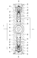
ポンプ10は、ピストンポンプが好ましい。そのピストンポンプを還流経路8に2個設けた例を図2に示す。図示したように、ポンプハウジング21には、2個の段付内孔10aがカム室22を間に挟んで対向して設けられている。
また、2つの吸入口23と2つの吐出口24がポンプハウジング21に設けられ、各段付内孔10aにピストン10bが組み込まれ、そのピストンを戻すピストンリターンスプリング10cがシリンダ孔27aの形成されたシリンダ部材27との間に組み込まれている。さらに、ポンプ室10dの上流側と下流側に吸入弁10eと吐出弁10fが各ピストン10bに対応させてそれぞれ設けられて2個のポンプ10,10が構成されている。
10gは、各ピストン10bに固定したリテーナであり、このリテーナ10gとピストン10bとの間に吸入弁10eが設けられ、さらに、ポンプハウジング21に液密に装着したキャップ28とシリンダ部材27との間に吐出弁10fが設けられている。吸入弁10eと吐出弁10fは、どちらも弁体とそれを閉弁方向に付勢するスプリングとからなる周知の弁を示したが、これに限定されるものではない。
2つの吸入口23は、1つに合流させて減圧用電磁弁9の排出ポートにつながれる。また、2つの吐出口24は、1つに合流させて増圧用電磁弁7の導入ポートにつながれる。
カム室22内には、中心から偏心した位置に駆動軸(これはモータ11の出力軸又はその出力軸に連結された回転軸)25をもつ円形の偏心カム26が組み込まれており、その偏心カム26の外周のカム面によって2つのポンプのピストン10bが交互に押し込まれる。2つのポンプ10,10は、動作の位相が180°ずれており、これにより、どちらか一方のポンプが吸入態勢を、他方のポンプが吐出態勢を常に維持することになる。
その2個のポンプ10,10が並列配置にして還流経路8に組み込まれているので、ホイールシリンダからの排出液を取り込むリザーバがなくても、減圧指令に迅速に応答してホイールシリンダ圧を降下させることができ、アンチロック制御の信頼性を確保することができる。
また、ポンプハウジングにリザーバを内蔵させる必要がないため、装置の小型化が図れる。2個のピストンポンプを対向配置した例示の装置は、例えば、図2の上下方向についてポンプハウジングの小型化も図れる。
また、ブレーキ液圧制御装置に採用するピストンポンプの中には、自吸入機能を備えたもの(例えば、特開2011-64166号公報)もあり、この発明の装置は、そのようなピストンポンプを採用することもできる。
図1の後輪系のブレーキ装置RBは、ブレーキレバー13を操作して作動させてブレーキ液圧を発生させるマスタシリンダ14と、そのマスタシリンダ14から供給されるブレーキ液圧を受けてブレーキピストンなどを作動させるホイールシリンダ15とで構成される液圧制御機能の無い一般的な液圧式のブレーキ装置である。マスタシリンダ14にはリザーバ16が付属している。この系のブレーキ装置は、機械式のもので代替することも考えられる。
この発明のブレーキ液圧制御装置は、自動2輪車のほかに、自動3輪車にも利用することができる。自動3輪車には、前輪が1輪のものと前輪が2輪のものの2タイプがある。適用対象が後者の自動3輪車の場合には、液圧経路6の下流側を2つに分岐して各分岐路をホイールシリンダにつなぐことになる。
1 ブレーキ液圧制御装置
2,13 ブレーキレバー
3,14 マスタシリンダ
4,15 ホイールシリンダ
5,16 リザーバ
6 液圧経路
7 増圧用電磁弁
8 還流経路
9 減圧用電磁弁
10 ポンプ
10a 段付内孔
10b ピストン
10c ピストンリターンスプリング
10d ポンプ室
10e 吸入弁
10f 吐出弁
10g リテーナ
11 モータ
12 電子制御装置
21 ポンプハウジング
22 カム室
23 吸入口
24 吐出口
25 駆動軸
26 偏心カム
27 シリンダ部材
27a シリンダ孔
28 キャップ
FB 前輪系のブレーキ装置
RB 後輪系のブレーキ装置
C 合流点
2,13 ブレーキレバー
3,14 マスタシリンダ
4,15 ホイールシリンダ
5,16 リザーバ
6 液圧経路
7 増圧用電磁弁
8 還流経路
9 減圧用電磁弁
10 ポンプ
10a 段付内孔
10b ピストン
10c ピストンリターンスプリング
10d ポンプ室
10e 吸入弁
10f 吐出弁
10g リテーナ
11 モータ
12 電子制御装置
21 ポンプハウジング
22 カム室
23 吸入口
24 吐出口
25 駆動軸
26 偏心カム
27 シリンダ部材
27a シリンダ孔
28 キャップ
FB 前輪系のブレーキ装置
RB 後輪系のブレーキ装置
C 合流点
Claims (4)
- マスタシリンダ(3)と、そのマスタシリンダ(3)から供給される液圧を受けて作動するホイールシリンダ(4)との間の液圧経路(6)に組み込まれるブレーキ液圧制御装置(1)であって、単一の増圧用電磁弁(7)と、前記液圧経路(6)に前記増圧用電磁弁(7)と並列配置にして設ける還流経路(8)と、その還流経路(8)に挿入する単一の減圧用電磁弁(9)と、前記還流経路(8)の途中に組み込まれて減圧用電磁弁(9)経由で前記ホイールシリンダ(4)から排出されるブレーキ液を直接汲み上げて前記液圧経路(6)の前記マスタシリンダ(3)と前記減圧用電磁弁(9)との間に還流させる複数のポンプ(10)と、各ポンプ(10)を一括して駆動する単一のモータ(11)と、前記ホイールシリンダ(4)の減圧、再加圧の必要性を判断して前記減圧用電磁弁(9)と増圧用電磁弁(7)に制御指令を出す電子制御装置(12)を有し、
前記複数のポンプ(10)が動作行程の位相を異ならせて前記還流経路(8)に並列配置にして組み込まれたブレーキ液圧制御装置。 - 前記ポンプ(10)をピストンポンプとし、そのピストンポンプを前記モータ(11)によって回転させるピストン駆動用のカム(26)を中心にして放射状に配置した請求項1に記載のブレーキ液圧制御装置。
- 前記ピストン駆動用のカム(26)が、中心から偏心した位置に駆動軸をもつ円形の偏心カムである請求項2に記載のブレーキ液圧制御装置。
- 前輪系、後輪系のうち、どちらか一方のブレーキ系に請求項1~3のいずれかに記載のブレーキ液圧制御装置を備えさせ、他方のブレーキ系に、マスタシリンダで発生させた液圧を制御せずにホイールシリンダに供給する液圧ブレーキ装置もしくは機械式ブレーキ装置を備えさせた自動2輪車又は自動3輪車用のブレーキ装置。
Applications Claiming Priority (2)
| Application Number | Priority Date | Filing Date | Title |
|---|---|---|---|
| JP2011118159A JP2012245855A (ja) | 2011-05-26 | 2011-05-26 | ブレーキ液圧制御装置とそれを用いたブレーキ装置 |
| JP2011-118159 | 2011-05-26 |
Publications (1)
| Publication Number | Publication Date |
|---|---|
| WO2012161311A1 true WO2012161311A1 (ja) | 2012-11-29 |
Family
ID=47217376
Family Applications (1)
| Application Number | Title | Priority Date | Filing Date |
|---|---|---|---|
| PCT/JP2012/063482 Ceased WO2012161311A1 (ja) | 2011-05-26 | 2012-05-25 | ブレーキ液圧制御装置とそれを用いたブレーキ装置 |
Country Status (2)
| Country | Link |
|---|---|
| JP (1) | JP2012245855A (ja) |
| WO (1) | WO2012161311A1 (ja) |
Cited By (3)
| Publication number | Priority date | Publication date | Assignee | Title |
|---|---|---|---|---|
| WO2016055191A1 (de) * | 2014-10-09 | 2016-04-14 | Robert Bosch Gmbh | Elektronisch schlupfregelbare fahrzeugbremsanlage |
| WO2016203332A1 (ja) * | 2015-06-15 | 2016-12-22 | ローベルト ボッシュ ゲゼルシャフト ミット ベシュレンクテル ハフツング | 液圧制御装置、および、そのような液圧制御装置の製造方法 |
| CN110525570A (zh) * | 2018-05-23 | 2019-12-03 | 株式会社岛野 | 驱动装置及驱动系统 |
Families Citing this family (2)
| Publication number | Priority date | Publication date | Assignee | Title |
|---|---|---|---|---|
| JP5979751B2 (ja) * | 2012-07-25 | 2016-08-31 | ボッシュ株式会社 | ブレーキ液圧制御装置 |
| JP7196495B2 (ja) * | 2018-09-25 | 2022-12-27 | 株式会社アドヴィックス | 車両の制動制御装置 |
Citations (4)
| Publication number | Priority date | Publication date | Assignee | Title |
|---|---|---|---|---|
| JPH10203330A (ja) * | 1997-01-20 | 1998-08-04 | Denso Corp | 車両用ブレーキ装置 |
| JP2005180332A (ja) * | 2003-12-19 | 2005-07-07 | Aisan Ind Co Ltd | プランジャポンプ及びエンジン用流体ポンプ |
| JP2008095523A (ja) * | 2006-10-06 | 2008-04-24 | Toflo Corporation Kk | ポンプヘッド及びそれを用いた往復ポンプ装置 |
| JP2010229870A (ja) * | 2009-03-26 | 2010-10-14 | Nissin Kogyo Co Ltd | ソレノイドポンプ |
-
2011
- 2011-05-26 JP JP2011118159A patent/JP2012245855A/ja active Pending
-
2012
- 2012-05-25 WO PCT/JP2012/063482 patent/WO2012161311A1/ja not_active Ceased
Patent Citations (4)
| Publication number | Priority date | Publication date | Assignee | Title |
|---|---|---|---|---|
| JPH10203330A (ja) * | 1997-01-20 | 1998-08-04 | Denso Corp | 車両用ブレーキ装置 |
| JP2005180332A (ja) * | 2003-12-19 | 2005-07-07 | Aisan Ind Co Ltd | プランジャポンプ及びエンジン用流体ポンプ |
| JP2008095523A (ja) * | 2006-10-06 | 2008-04-24 | Toflo Corporation Kk | ポンプヘッド及びそれを用いた往復ポンプ装置 |
| JP2010229870A (ja) * | 2009-03-26 | 2010-10-14 | Nissin Kogyo Co Ltd | ソレノイドポンプ |
Cited By (4)
| Publication number | Priority date | Publication date | Assignee | Title |
|---|---|---|---|---|
| WO2016055191A1 (de) * | 2014-10-09 | 2016-04-14 | Robert Bosch Gmbh | Elektronisch schlupfregelbare fahrzeugbremsanlage |
| WO2016203332A1 (ja) * | 2015-06-15 | 2016-12-22 | ローベルト ボッシュ ゲゼルシャフト ミット ベシュレンクテル ハフツング | 液圧制御装置、および、そのような液圧制御装置の製造方法 |
| CN110525570A (zh) * | 2018-05-23 | 2019-12-03 | 株式会社岛野 | 驱动装置及驱动系统 |
| CN110525570B (zh) * | 2018-05-23 | 2022-02-11 | 株式会社岛野 | 驱动装置及驱动系统 |
Also Published As
| Publication number | Publication date |
|---|---|
| JP2012245855A (ja) | 2012-12-13 |
Similar Documents
| Publication | Publication Date | Title |
|---|---|---|
| KR101729940B1 (ko) | 전자제어식 브레이크 시스템의 펌프유닛 | |
| KR101187196B1 (ko) | 브레이크 시스템 | |
| US20100264723A1 (en) | Brake fluid pressure control device | |
| JPH01297349A (ja) | アンチスキッド制御装置 | |
| US20110074208A1 (en) | Pump unit for electronic control brake system | |
| US11554764B2 (en) | Hydraulic pressure control unit for straddle-type vehicle brake system and straddle-type vehicle brake system | |
| JP2012245855A (ja) | ブレーキ液圧制御装置とそれを用いたブレーキ装置 | |
| JP2006347538A (ja) | 電子制御式ブレーキシステム | |
| JP5102754B2 (ja) | 車両用ブレーキ液圧制御装置 | |
| KR20150071323A (ko) | 유압 브레이크 시스템 | |
| JP6709289B2 (ja) | ブレーキ液圧制御ユニット、モータサイクル用のブレーキシステム、及び、モータサイクル | |
| JP5979751B2 (ja) | ブレーキ液圧制御装置 | |
| JP4922111B2 (ja) | 車両用ブレーキ油圧制御装置 | |
| US20110074205A1 (en) | Pump unit for electronically controlled brake system | |
| KR100771018B1 (ko) | 전자제어식 브레이크 시스템의 펌프 | |
| JP6873013B2 (ja) | ポンプ装置及びブレーキ装置 | |
| KR100550949B1 (ko) | 전자제어식 브레이크 장치용 펌프 | |
| KR20130119109A (ko) | 펌프유닛 및 이를 구비하는 전자제어식 브레이크 시스템 | |
| US20110074206A1 (en) | Pump unit for electronically controlled brake system | |
| JP2025094404A (ja) | ブレーキ液圧制御装置および鞍乗型車両 | |
| KR101908012B1 (ko) | 유압 브레이크 시스템 | |
| KR100808011B1 (ko) | 안티록 브레이크 시스템용 펌프 | |
| KR101622153B1 (ko) | 유압 브레이크 시스템 | |
| KR101207804B1 (ko) | 전자제어식 브레이크 시스템 | |
| JP4815416B2 (ja) | プランジャ式ポンプ |
Legal Events
| Date | Code | Title | Description |
|---|---|---|---|
| 121 | Ep: the epo has been informed by wipo that ep was designated in this application |
Ref document number: 12789113 Country of ref document: EP Kind code of ref document: A1 |
|
| NENP | Non-entry into the national phase |
Ref country code: DE |
|
| 122 | Ep: pct application non-entry in european phase |
Ref document number: 12789113 Country of ref document: EP Kind code of ref document: A1 |