WO2012161284A1 - 無線通信装置及び通信制御方法 - Google Patents
無線通信装置及び通信制御方法 Download PDFInfo
- Publication number
- WO2012161284A1 WO2012161284A1 PCT/JP2012/063390 JP2012063390W WO2012161284A1 WO 2012161284 A1 WO2012161284 A1 WO 2012161284A1 JP 2012063390 W JP2012063390 W JP 2012063390W WO 2012161284 A1 WO2012161284 A1 WO 2012161284A1
- Authority
- WO
- WIPO (PCT)
- Prior art keywords
- wireless communication
- control
- frequency
- communication device
- antenna
- Prior art date
- Legal status (The legal status is an assumption and is not a legal conclusion. Google has not performed a legal analysis and makes no representation as to the accuracy of the status listed.)
- Ceased
Links
Images



Classifications
-
- H—ELECTRICITY
- H04—ELECTRIC COMMUNICATION TECHNIQUE
- H04B—TRANSMISSION
- H04B7/00—Radio transmission systems, i.e. using radiation field
- H04B7/02—Diversity systems; Multi-antenna system, i.e. transmission or reception using multiple antennas
- H04B7/10—Polarisation diversity; Directional diversity
-
- H—ELECTRICITY
- H04—ELECTRIC COMMUNICATION TECHNIQUE
- H04B—TRANSMISSION
- H04B7/00—Radio transmission systems, i.e. using radiation field
- H04B7/02—Diversity systems; Multi-antenna system, i.e. transmission or reception using multiple antennas
- H04B7/04—Diversity systems; Multi-antenna system, i.e. transmission or reception using multiple antennas using two or more spaced independent antennas
- H04B7/06—Diversity systems; Multi-antenna system, i.e. transmission or reception using multiple antennas using two or more spaced independent antennas at the transmitting station
- H04B7/0613—Diversity systems; Multi-antenna system, i.e. transmission or reception using multiple antennas using two or more spaced independent antennas at the transmitting station using simultaneous transmission
- H04B7/0615—Diversity systems; Multi-antenna system, i.e. transmission or reception using multiple antennas using two or more spaced independent antennas at the transmitting station using simultaneous transmission of weighted versions of same signal
- H04B7/0617—Diversity systems; Multi-antenna system, i.e. transmission or reception using multiple antennas using two or more spaced independent antennas at the transmitting station using simultaneous transmission of weighted versions of same signal for beam forming
Definitions
- the present invention relates to a multicarrier wireless communication apparatus that receives a wireless signal using a plurality of antennas, and a communication control method in the wireless communication apparatus.
- a multi-carrier wireless communication apparatus that receives a wireless signal using a plurality of antennas employs an interference suppression technique.
- the wireless communication device sets an antenna weight for each antenna for adaptive array control (beamforming and null steering) based on the reception state of a known signal (pilot signal) that is a wireless signal. calculate.
- the wireless communication apparatus Considering frequency selective fading, it is desirable for the above-described wireless communication apparatus to calculate an antenna weight for each narrowest frequency band.
- the calculation of the antenna weight for each narrow frequency band by the wireless communication device leads to an increase in processing load on the wireless communication device.
- the wireless communication apparatus calculates an antenna weight corresponding to a wide frequency band, the processing load is reduced.
- the frequency selective fading is large, even if the wireless communication apparatus applies the calculated antenna weight, beam forming or null steering may not be performed appropriately.
- a first feature of the present invention is a multi-carrier wireless communication apparatus that receives a wireless signal using a plurality of antennas, and the wireless communication apparatus is considered to have high frequency selective fading. And performing multi-antenna control using each of a plurality of frequency bands as a unit of control, and performing multi-antenna control using the plurality of frequency bands as a unit of control when the frequency selective fading is considered to be small. And
- Such a radio communication apparatus performs multi-antenna control using each of a plurality of frequency bands as a unit of control when the frequency selective fading is considered to be large, and when the frequency selective fading is considered to be small. Performs multi-antenna control using the plurality of frequency bands as a unit of control. Therefore, when frequency selective fading is considered to be large, multi-antenna control is performed for each narrow frequency band, thereby enabling appropriate multi-antenna control, and when frequency selective fading is considered to be small. By performing multi-antenna control over a wide frequency band, it is possible to perform appropriate multi-antenna control while reducing the processing load.
- the gist of the present invention is that the wireless communication device calculates an antenna weight for each unit of control.
- the feature of the present invention is that the wireless communication apparatus calculates at least one of an antenna weight for beam forming and an antenna weight for null steering.
- a feature of the present invention is that the wireless communication device applies the antenna weight to a frequency band to be estimated.
- the gist of the present invention is that the wireless communication apparatus determines that frequency selective fading is large when a difference in received power between known signals distributed in the frequency direction is equal to or greater than a threshold value. .
- a feature of the present invention is a communication control method in a multi-carrier wireless communication apparatus that receives a wireless signal using a plurality of antennas, and the wireless communication apparatus is considered to have large frequency selective fading Performing multi-antenna control with each of a plurality of frequency bands as a unit of control, and when the frequency selective fading is considered to be small, performing the multi-antenna control with the plurality of frequency bands as a unit of control It is made to include.
- FIG. 1 is an overall schematic configuration diagram of a radio communication system according to an embodiment of the present invention.
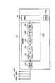
- FIG. 2 is a configuration diagram of a wireless terminal according to the embodiment of the present invention.
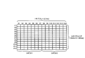
- FIG. 3 is a diagram illustrating a PDSCH format according to an embodiment of the present invention.
- FIG. 4 is a diagram showing an arrangement of known signals according to the embodiment of the present invention.
- FIG. 5 is a diagram illustrating an example of frequency selective fading according to the embodiment of the present invention.
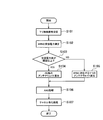
- FIG. 6 is a flowchart showing the operation of the wireless terminal according to the embodiment of the present invention.
- FIG. 1 is an overall schematic configuration diagram of a radio communication system 10 according to an embodiment of the present invention.
- a wireless communication system 10 shown in FIG. 1 is a wireless communication system corresponding to LTE (Long Term Evolution) for which a standard has been established in 3GPP (Third Generation Partnership Project).
- the radio communication system 10 includes a radio terminal (UE1) and a radio base station (eNB) 2.
- eNB 2 constitutes E-UTRAN (Evolved-UMTS Terrestrial Radio Access Network) together with other eNBs not shown.
- UE1 exists in the cell 3 which is a communicable area which eNB2 provides. In FIG. 1, only one UE 1 is shown, but a plurality of UEs 1 actually exist in the cell 3.
- OFDMA Orthogonal Frequency Division Multiplexing Access
- SC-FDMA Single Carrier Frequency Frequency Division Multiple Access
- ENB 2 allocates a resource block (RB: Resource Block) as a radio resource to UE 1 in cell 3.
- RB Resource Block
- the resource block includes a downlink resource block (downlink RB) used for downlink radio communication and an uplink resource block (uplink RB) used for uplink radio communication.
- a plurality of downlink resource blocks are arranged in the frequency direction.
- a plurality of uplink resource blocks are arranged in the frequency direction.
- the downlink resource block is transmitted in the time direction by a control information channel (PDCCH: Physical-Downlink-Control-CHannel) for downlink control information transmission and a shared data channel (PDSCH: Physical-Downlink-Shared-CHannel) for downlink user data transmission. Composed.
- a control information channel (PDCCH: Physical-Downlink-Control-CHannel) for downlink control information transmission
- PDSCH Physical-Downlink-Shared-CHannel
- control information channels (PUCCH: Physical Uplink Control nel CHannel) for uplink control information transmission are configured at both ends of all frequency bands that can be used for uplink radio communication.
- a shared data channel (PUSCH: Physical-Uplink-Shared-CHannel) for user data transmission is configured.
- FIG. 2 is a configuration diagram of UE1.
- UE1 is an adaptive array radio terminal, and includes a control unit 102, a storage unit 103, a radio frequency (RF) reception processing unit 104, and a base band (BB) processing unit.
- RF radio frequency
- BB base band
- 106 array antenna 108A, array antenna 108B, array antenna 108C, and array antenna 108D.
- UE1 shown in FIG. 2 has shown only the structure required in this embodiment.
- the control unit 102 is configured by a CPU, for example, and controls various functions provided in the UE1.
- storage part 103 is comprised by memory, for example, and memorize
- the RF reception processing unit 104 receives a downlink radio signal in the radio frequency band from the eNB 2 via the array antenna 108A to the array antenna 108D.
- the RF reception processing unit 104 includes a low noise amplifier (LNA: Low Noise Amplifier) and a mixer (not shown).
- LNA Low Noise Amplifier
- the RF reception processing unit 104 amplifies the received downlink radio signal in the radio frequency band, and converts (down-converts) it into a baseband signal. Further, the RF reception processing unit 104 outputs the baseband signal to the BB processing unit 106.
- LNA Low Noise Amplifier
- the BB processing unit 106 includes a CP (Cyclic Prefix) removal unit 122, an FFT (Fast Fourier Transform) processing unit 124, an AAS (Adaptive Array System) processing unit 126, a channel equalization unit 128, and a demodulation decoding unit 130.
- CP Cyclic Prefix
- FFT Fast Fourier Transform
- AAS Adaptive Array System
- CP removing unit 122 removes CP (Cyclic Prefix) from the input baseband signal.
- the CP is a copy of the end part of the OFDM symbol, and is included in a guard interval period provided to suppress intersymbol interference caused by multipath.
- the FFT processing unit 124 performs a fast Fourier transform on the baseband signal from which the CP has been removed to obtain a frequency domain signal.
- the AAS processing unit 126 determines, for each of the array antennas 108A to 108D, an antenna weight (SINR) that maximizes the signal-to-interference noise ratio (SINR) when receiving a downlink radio signal from the eNB2. Receive weight) is calculated.
- SINR antenna weight
- FIG. 3 is a diagram illustrating a PDCCH format corresponding to one resource block (RB).
- the PDCCH is configured by one subframe having a time length of 1 [ms] in the time direction.
- the subframe includes time zones S1 to S14. Of these time zones S1 to S14, time zones S1 to S7 constitute the first half slot (slot 1), and time zones S8 to S14 constitute the second half slot (slot 2). .
- the central time zone S4 in the slot 1 is used for transmission of a pilot signal which is a known signal.
- the central time zone S11 in the slot 2 is used for transmission of a pilot signal which is a known signal.
- the PDCCH has a frequency width of 180 [kHz] in the frequency direction.
- the PDCCH is composed of 12 subcarriers F1 to F12 having a frequency width of 15 [kHz].
- FIG. 4 is a diagram showing the arrangement of pilot signals. As shown in FIG. 4, in this embodiment, subcarriers used for pilot signal transmission are arranged at three subcarrier intervals. Focusing on one downlink resource block, subcarriers F3, F7, and F11 are subcarriers used for transmission of pilot signals.
- the AAS processing unit 126 calculates the reception weight as follows. In the following, it is assumed that four downlink resource blocks having continuous frequencies are allocated to UE1.
- the AAS processing unit 126 detects a pilot signal included in a frequency domain signal corresponding to four downlink resource blocks. As described above, one pilot resource block includes three pilot signals. Therefore, the AAS processing unit 126 detects 12 pilot signals included in the frequency domain signal corresponding to the four downlink resource blocks.
- the AAS processing unit 126 measures the received power of the 12 detected pilot signals. Next, the AAS processing unit 126 acquires a difference (received power difference) between the maximum received power and the minimum received power among the measured received powers.
- the AAS processing unit 126 considers that frequency selective fading is large when the received power difference is equal to or greater than a predetermined threshold value ⁇ . In this case, the AAS processing unit 126 determines to calculate a reception weight for each downlink resource block. On the other hand, if the received power difference is less than the predetermined threshold value ⁇ , the AAS processing unit 126 considers that the frequency selective fading is small. In this case, the AAS processing unit 126 determines to calculate one reception weight corresponding to four downlink resource blocks.
- FIG. 5 is a diagram illustrating an example of frequency selective fading.
- FIG. 5A shows a large received power difference d
- FIG. 5B shows a small received power difference d.
- the AAS processing unit 126 determines to calculate the reception weight for each downlink resource block when the received power difference d in FIG.
- the reception power difference d in FIG. 5B is less than the threshold value ⁇
- the AAS processing unit 126 determines to calculate one reception weight corresponding to four downlink resource blocks.
- the AAS processing unit 126 When calculating the reception weight for each downlink resource block, the AAS processing unit 126 derives one reception power value for each downlink resource block from the reception power values of three pilot signals included in the downlink resource block. To do. For example, the AAS processing unit 126 calculates an average value of received power values of three pilot signals. Alternatively, the AAS processing unit 126 acquires an intermediate value that is the second largest value among the received power values of the three pilot signals.
- the AAS processing unit 126 calculates a reception weight corresponding to the PUSCH frequency band in one downlink resource block based on one derived reception power value.
- the above processing is performed for each of the four downlink resource blocks and for each of the array antennas 108A to 108D, so that 16 reception weights are calculated.
- the AAS processing unit 126 determines one reception power value from reception power values of twelve pilot signals included in the four downlink resource blocks. Is derived. For example, the AAS processing unit 126 calculates an average value of received power values of 12 pilot signals. Alternatively, the AAS processing unit 126 acquires an intermediate value that is the sixth or seventh largest value among the received power values of the twelve pilot signals.
- the AAS processing unit 126 calculates reception weights corresponding to the PUSCH frequency bands in the four downlink resource blocks based on the derived one received power value.
- the above processing is performed for each of the array antennas 108A to 108D, whereby four reception weights are calculated.
- the AAS processing unit 126 applies the reception weight to the corresponding frequency band for channel estimation. Specifically, the AAS processing unit 126 performs weighting processing for combining the calculated reception weights and the frequency domain signals that are sequentially input. Further, the AAS processing unit 126 outputs the frequency domain signal from the FFT processing unit 124 to the channel equalization unit 128.
- the channel equalization unit 128 performs channel equalization processing on the input frequency domain signal.
- the demodulation / decoding unit 130 performs demodulation and decoding processing on the channel-equalized signal. Thereby, data transmitted by the eNB 2 is obtained. Data is output to the control unit 102.
- FIG. 6 is a flowchart showing the operation of UE1.
- step S101 eNB2 transmits a downlink radio signal in a radio frequency band using four downlink resource blocks having continuous frequencies.
- UE1 receives a downlink radio signal in a radio frequency band.
- step S102 UE1 measures the received power of the pilot signal included in the downlink radio signal corresponding to the received four downlink resource blocks.
- step S103 the UE 1 determines whether or not the difference (reception power difference) d between the maximum reception power value and the minimum reception power value among the reception power values of the pilot signal is equal to or greater than the threshold value ⁇ .
- step S104 the UE1 calculates an antenna weight (reception weight) for each downlink resource block.
- step S105 UE1 calculates one antenna weight (reception weight) corresponding to four downlink resource blocks.
- step S106 the UE 1 performs a process (AAS process) for applying the reception weight to the corresponding frequency band to be estimated.
- AAS process a process for applying the reception weight to the corresponding frequency band to be estimated.
- step S107 UE1 performs channel equalization processing.
- the difference in received power values of the downlink radio signal is equal to or greater than a threshold value.
- the reception weight is calculated for each downlink resource block, and when the difference between the reception power values of the downlink radio signals is less than the threshold, one reception weight corresponding to four resource blocks is calculated.
- UE1 performs AAS using the calculated reception weight and channel equalization processing.
- the UE 1 can perform appropriate multi-antenna control by performing multi-antenna control for each narrow frequency band, and the frequency selective fading is considered to be small. In, by performing multi-antenna control in a wide frequency band, it is possible to perform appropriate multi-antenna control while reducing the processing load.
- the UE 1 calculates the reception weight for each downlink resource block based on the difference in the reception power value of the pilot signal included in the downlink radio signal, and one reception weight corresponding to four downlink resource blocks. The calculation was switched. However, the UE 1 calculates a reception weight for each downlink resource block based on a difference in received power of other known signals included in the downlink radio signal and calculates one reception weight corresponding to four downlink resource blocks. May be switched.
- the UE 1 calculates the reception weight for each downlink resource block and is less than the threshold. In this case, one reception weight corresponding to four downlink resource blocks was calculated.
- the reception weight calculation method is not limited to this.
- UE1 calculates one reception weight corresponding to the first predetermined number of downlink resource blocks when the difference between the received power values of the pilot signals included in the downlink radio signal is equal to or greater than the threshold, and less than the threshold In some cases, one reception weight corresponding to more downlink resource blocks than the first predetermined number may be calculated.
- the UE 1 that is an LTE radio terminal has been described.
- the present invention can be similarly applied to any multi-carrier radio communication apparatus that receives a radio signal using a plurality of antennas.
Landscapes
- Engineering & Computer Science (AREA)
- Computer Networks & Wireless Communication (AREA)
- Signal Processing (AREA)
- Radio Transmission System (AREA)
- Mobile Radio Communication Systems (AREA)
Abstract
複数のアンテナを用いて、無線信号を受信するマルチキャリア方式の無線通信装置は、周波数選択性フェージングが大きいと見なされる場合においては、複数の周波数帯のそれぞれを制御の単位としてマルチアンテナ制御を行い、前記周波数選択性フェージングが小さいと見なされる場合においては、前記複数の周波数帯を制御の単位としてマルチアンテナ制御を行う。
Description
本発明は、複数のアンテナを用いて、無線信号を受信するマルチキャリア方式の無線通信装置、及び、当該無線通信装置における通信制御方法に関する。
従来より、複数のアンテナを用いて、無線信号を受信するマルチキャリア方式の無線通信装置は、干渉抑圧の技術を採用している。例えば、特許文献1では、無線通信装置は、無線信号である既知信号(パイロット信号)の受信状況に基づいて、アダプティブアレイ制御(ビームフォーミング及びヌルステアリング)のために、各アンテナ毎にアンテナウェイトを算出する。
周波数選択性フェージングを考慮すると、上述した無線通信装置は、できるだけ狭い周波数帯毎にアンテナウェイトを算出することが望ましい。しかしながら、無線通信装置が、狭い周波数帯域毎にアンテナウェイトを算出することが、当該無線通信装置の処理負担の増大をもたらす。一方、無線通信装置が、広い周波数帯に対応するアンテナウェイトを算出する場合には、処理負担は小さくなる。しかしながら、周波数選択性フェージングが大きい場合においては、無線通信装置が、算出したアンテナウェイトを適用しても、適切にビームフォーミングやヌルステアリングが行われない場合がある。
本発明の第1の特徴は、複数のアンテナを用いて、無線信号を受信するマルチキャリア方式の無線通信装置であって、前記無線通信装置は、周波数選択性フェージングが大きいと見なされる場合においては、複数の周波数帯のそれぞれを制御の単位としてマルチアンテナ制御を行い、前記周波数選択性フェージングが小さいと見なされる場合においては、前記複数の周波数帯を制御の単位としてマルチアンテナ制御を行うことを要旨とする。
このような無線通信装置は、周波数選択性フェージングが大きいと見なされる場合においては、複数の周波数帯のそれぞれを制御の単位としてマルチアンテナ制御を行い、前記周波数選択性フェージングが小さいと見なされる場合においては、前記複数の周波数帯を制御の単位としてマルチアンテナ制御を行う。従って、周波数選択性フェージングが大きいと見なされる場合においては、狭い周波数帯毎にマルチアンテナ制御が行われることにより、適切なマルチアンテナ制御が可能となり、周波数選択性フェージングが小さいと見なされる場合においては、広い周波数帯でマルチアンテナ制御が行われることにより、処理負荷を軽減しつつ、適切なマルチアンテナ制御が可能となる。
本発明の特徴は、前記無線通信装置は、前記制御の単位毎にアンテナウェイトを算出することを要旨とする。
本発明の特徴は、前記無線通信装置は、ビームフォーミング用のアンテナウェイト及びヌルステアリング用のアンテナウェイトの少なくとも何れかを算出することを要旨とする。
本発明の特徴は、前記無線通信装置は、前記アンテナウェイトを推定対象の周波数帯域に適用することを要旨とする。
本発明の特徴は、前記無線通信装置は、周波数方向に分散して配置される既知信号の受信電力の差が閾値以上である場合に、周波数選択性フェージングが大きいと判断することを要旨とする。
本発明の特徴は、複数のアンテナを用いて、無線信号の受信を行うマルチキャリア方式の無線通信装置における通信制御方法であって、前記無線通信装置が、周波数選択性フェージングが大きいと見なされる場合においては、複数の周波数帯のそれぞれを制御の単位としてマルチアンテナ制御を行い、前記周波数選択性フェージングが小さいと見なされる場合においては、前記複数の周波数帯を制御の単位としてマルチアンテナ制御を行うステップを含むことを要旨とする。
次に、図面を参照して、本発明の実施形態を説明する。具体的には、無線通信システムの構成、無線端末の動作、その他の実施形態について説明する。以下の実施形態における図面の記載において、同一又は類似の部分には同一又は類似の符号を付している。
(1)無線通信システムの構成
(1.1)無線通信システムの全体概略構成
図1は、本発明の実施形態に係る無線通信システム10の全体概略構成図である。
(1.1)無線通信システムの全体概略構成
図1は、本発明の実施形態に係る無線通信システム10の全体概略構成図である。
図1に示す無線通信システム10は、3GPP(Third Generation Partnership Project)において、規格が策定されたLTE(Long Term Evolution)に対応する無線通信システムである。無線通信システム10は、無線端末(UE1)と、無線基地局(eNB)2とを含む。
図1において、eNB2は、図示しない他のeNBとともに、E-UTRAN(Evolved-UMTS Terrestrial Radio Access Network)を構成する。UE1は、eNB2が提供する通信可能エリアであるセル3に存在する。なお、図1では、UE1は、1つのみが示されているが、実際には複数のUE1がセル3内に存在する。
eNB2と、UE1との間の下りの無線通信にはOFDMA(Orthogonal Frequency Division Multiplexing Access)、上りの無線通信にはSC-FDMA(Single Carrier Frequency Division Multiple Access)が採用される。ここで、下りとは、eNB2からUE1へ向かう方向を意味し、上りとは、UE1からeNB2へ向かう方向を意味する。
eNB2は、セル3内のUE1に対して、無線リソースとしてのリソースブロック(RB:Resource Block)を割り当てる。
リソースブロックは、下りの無線通信に用いられる下りリソースブロック(下りRB)と、上りの無線通信に用いられる上りリソースブロック(上りRB)とがある。複数の下りリソースブロックは、周波数方向に配列される。同様に、複数の上りリソースブロックは、周波数方向に配列される。
下りリソースブロックは、時間方向に、下りの制御情報伝送用の制御情報チャネル(PDCCH:Physical Downlink Control CHannel)と、下り方向のユーザデータ伝送用の共有データチャネル(PDSCH:Physical Downlink Shared CHannel)とにより構成される。
一方、上りリソースブロックは、上りの無線通信に使用可能な全周波数帯の両端に、上りの制御情報伝送用の制御情報チャネル(PUCCH:Physical Uplink Control CHannel)が構成され、中央部に、上りのユーザデータ伝送用の共有データチャネル(PUSCH:Physical Uplink Shared CHannel)が構成される。
以下、eNB2とUE1との間で無線通信が行われる場合について説明する。なお、以下では、初期状態において、UE1には下りリソースブロックと上りリソースブロックとが割り当てられているものとする。
(1.2)無線端末の構成
図2は、UE1の構成図である。図2に示すように、UE1は、アダプティブアレイ方式の無線端末であり、制御部102、記憶部103、無線周波数(RF:Radio Frequency)受信処理部104、ベースバンド(BB:Base band)処理部106、アレイアンテナ108A、アレイアンテナ108B、アレイアンテナ108C、アレイアンテナ108Dを含む。なお、図2に示すUE1は、本実施形態において必要な構成のみを示している。
図2は、UE1の構成図である。図2に示すように、UE1は、アダプティブアレイ方式の無線端末であり、制御部102、記憶部103、無線周波数(RF:Radio Frequency)受信処理部104、ベースバンド(BB:Base band)処理部106、アレイアンテナ108A、アレイアンテナ108B、アレイアンテナ108C、アレイアンテナ108Dを含む。なお、図2に示すUE1は、本実施形態において必要な構成のみを示している。
制御部102は、例えばCPUによって構成され、UE1が具備する各種機能を制御する。記憶部103は、例えばメモリによって構成され、UE1における制御などに用いられる各種情報を記憶する。
RF受信処理部104は、アレイアンテナ108A乃至アレイアンテナ108Dを介して、eNB2からの無線周波数帯の下り無線信号を受信する。RF受信処理部104は、図示しないローノイズアンプ(LNA:Low Noise Amplifier)、ミキサを内蔵している。RF受信処理部104は、受信した無線周波数帯の下り無線信号を増幅し、ベースバンド信号に変換(ダウンコンバート)する。更に、RF受信処理部104は、ベースバンド信号をBB処理部106へ出力する。
BB処理部106は、CP(Cyclic Prefix)除去部122、FFT(Fast Fourier Transform)処理部124、AAS(Adaptive Array System)処理部126、チャネル等化部128、復調復号部130を含む。
CP除去部122は、入力されたベースバンド信号からCP(Cyclic Prefix)を除去する。CPは、OFDMシンボルの終わりの部分の複製であり、マルチパスによって引き起こされるシンボル間干渉を抑制するために設けられたガード・インターバルの期間に含まれる。FFT処理部124は、CPが除去されたベースバンド信号に対して、高速フーリエ変換を行い、周波数領域の信号を得る。
AAS処理部126は、周波数領域の信号に基づいて、各アレイアンテナ108A乃至アレイアンテナ108D毎に、eNB2からの下り無線信号の受信時において信号対干渉雑音比(SINR)が最大となるアンテナウェイト(受信ウェイト)を算出する。
図3は、1つのリソースブロック(RB)に対応するPDCCHのフォーマットを示す図である。図3に示すように、PDCCHは、時間方向では、1[ms]の時間長を有する1つのサブフレームによって構成される。サブフレームは、時間帯S1乃至時間帯S14からなる。これら時間帯S1乃至時間帯S14のうち、時間帯S1乃至時間帯S7は、前半のスロット(スロット1)を構成し、時間帯S8乃至時間帯S14は、後半のスロット(スロット2)を構成する。スロット1における中央の時間帯S4は、既知信号であるパイロット信号の伝送に用いられる。同様に、スロット2における中央の時間帯S11は、既知信号であるパイロット信号の伝送に用いられる。
また、図3に示すように、PDCCHは、周波数方向では、180[kHz]の周波数幅を有する。また、PDCCHは、15[kHz]の周波数幅を有する12個のサブキャリアF1乃至F12からなる。
図4は、パイロット信号の配置を示す図である。図4に示すように、本実施形態では、パイロット信号の伝送に用いられるサブキャリアは、3つのサブキャリア間隔で配置される。1つの下りリソースブロックに着目すると、サブキャリアF3、F7、F11が、パイロット信号の伝送に用いられるサブキャリアである。
AAS処理部126は、以下のようにして受信ウェイトを算出する。なお、以下において、UE1には、周波数が連続する4つの下りリソースブロックが割り当てられているものとする。
具体的には、AAS処理部126は、4つの下りリソースブロックに対応する周波数領域の信号に含まれる、パイロット信号を検出する。上述したように、1つの下りリソースブロックには、3つのパイロット信号が含まれる。従って、AAS処理部126は、4つの下りリソースブロックに対応する周波数領域の信号に含まれる、12個のパイロット信号を検出する。
AAS処理部126は、検出した12個のパイロット信号の受信電力を測定する。次に、AAS処理部126は、測定した受信電力のうち、最大の受信電力と最小の受信電力との差(受信電力差)を取得する。
AAS処理部126は、受信電力差が予め定められた閾値α以上である場合には、周波数選択性フェージングが大きいと見なす。この場合、AAS処理部126は、下りリソースブロック毎に受信ウェイトを算出することを決定する。一方、AAS処理部126は、受信電力差が予め定められた閾値α未満である場合には、周波数選択性フェージングが小さいと見なす。この場合、AAS処理部126は、4つの下りリソースブロックに対応する1つの受信ウェイトを算出することを決定する。
図5は、周波数選択性フェージングの一例を示す図である。図5(a)は、受信電力差dが大きく、図5(b)は、受信電力差dが小さい。AAS処理部126は、図5(a)における受信電力差dが閾値α以上である場合には、下りリソースブロック毎に受信ウェイトを算出することを決定する。また、AAS処理部126は、図5(b)における受信電力差dが閾値α未満である場合には、4つの下りリソースブロックに対応する1つの受信ウェイトを算出することを決定する。
下りリソースブロック毎の受信ウェイトを算出する場合には、AAS処理部126は、下りリソースブロックのそれぞれについて、当該下りリソースブロックに含まれる3つのパイロット信号の受信電力値から1つの受信電力値を導出する。例えば、AAS処理部126は、3つのパイロット信号の受信電力値の平均値を算出する。あるいは、AAS処理部126は、3つのパイロット信号の受信電力値のうち、2番目に大きな値である中間値を取得する。
次に、AAS処理部126は、導出した1つの受信電力値に基づいて、1つの下りリソースブロック内のPUSCHの周波数帯に対応する受信ウェイトを算出する。
上述の処理が、4つの下りリソースブロック毎、且つ、アレイアンテナ108A乃至アレイアンテナ108D毎に行われることにより、16個の受信ウェイトが算出される。
一方、4つの下りリソースブロックに対応する1つの受信ウェイトを算出する場合には、AAS処理部126は、4つの下りリソースブロックに含まれる12個のパイロット信号の受信電力値から1つの受信電力値を導出する。例えば、AAS処理部126は、12個のパイロット信号の受信電力値の平均値を算出する。あるいは、AAS処理部126は、12個のパイロット信号の受信電力値のうち、6番目あるいは7番目に大きな値である中間値を取得する。
次に、AAS処理部126は、導出した1つの受信電力値に基づいて、4つの下りリソースブロック内のPUSCHの周波数帯に対応する受信ウェイトを算出する。
上述の処理が、アレイアンテナ108A乃至アレイアンテナ108D毎に行われることにより、4個の受信ウェイトが算出される。
その後、AAS処理部126は、受信ウェイトを、対応するチャネル推定対象の周波数帯域に適用する。具体的には、AAS処理部126は、算出した受信ウェイトと、順次入力される周波数領域の信号とを合成する重み付け処理を行う。更に、AAS処理部126は、FFT処理部124からの周波数領域の信号をチャネル等化部128へ出力する。
チャネル等化部128は、入力された周波数領域の信号に対して、チャネル等化処理を行う。
復調復号部130は、チャネル等化処理がなされた信号に対して復調及び復号処理を行う。これにより、eNB2が送信したデータが得られる。データは制御部102へ出力される。
(2)無線端末の動作
図6は、UE1の動作を示すフローチャートである。
図6は、UE1の動作を示すフローチャートである。
ステップS101において、eNB2は、周波数の連続する4つの下りリソースブロックを用いて、無線周波数帯の下り無線信号を送信する。UE1は、無線周波数帯の下り無線信号を受信する。
ステップS102において、UE1は、受信した4つの下りリソースブロックに対応する下り無線信号に含まれるパイロット信号の受信電力を測定する。
ステップS103において、UE1は、パイロット信号の受信電力値のうち、最大の受信電力値と最小の受信電力値との差(受信電力差)dが閾値α以上であるか否かを判定する。
受信電力差dが閾値α以上である場合、ステップS104において、UE1は、下りリソースブロック毎にアンテナウェイト(受信ウェイト)を算出する。一方、受信電力差dが閾値α未満である場合、ステップS105において、UE1は、4つの下りリソースブロックに対応する1つのアンテナウェイト(受信ウェイト)を算出する。
ステップS104又はステップS105における受信ウェイトの算出後、ステップS106において、UE1は、受信ウェイトを、対応するチャネル推定対象の周波数帯域に適用する処理(AAS処理)を行う。
ステップS107において、UE1は、チャネル等化処理を行う。
以上説明したように、本実施形態によれば、UE1は、eNB2からの4つの下りリソースブロックを用いた下り無線信号を受信した場合、当該下り無線信号の受信電力値の差が閾値以上である場合には、下りリソースブロック毎に受信ウェイトを算出し、当該下り無線信号の受信電力値の差が閾値未満である場合には、4つのリソースブロックに対応する1つの受信ウェイトを算出する。更に、UE1は、算出した受信ウェイトを用いたAASと、チャネル等化処理とを行う。
従って、UE1は、周波数選択性フェージングが大きいと見なされる場合においては、狭い周波数帯毎にマルチアンテナ制御を行うことにより、適切なマルチアンテナ制御が可能となり、周波数選択性フェージングが小さいと見なされる場合においては、広い周波数帯でマルチアンテナ制御を行うことにより、処理負荷を軽減しつつ、適切なマルチアンテナ制御が可能となる。
(3)その他の実施形態
上記のように、本発明は実施形態によって記載したが、この開示の一部をなす論述及び図面はこの発明を限定するものであると理解すべきではない。この開示から当業者には様々な代替実施形態、実施例及び運用技術が明らかとなる。
上記のように、本発明は実施形態によって記載したが、この開示の一部をなす論述及び図面はこの発明を限定するものであると理解すべきではない。この開示から当業者には様々な代替実施形態、実施例及び運用技術が明らかとなる。
上述した実施形態では、UE1は、下り無線信号に含まれるパイロット信号の受信電力値の差に基づいて、下りリソースブロック毎の受信ウェイトの算出と、4つの下りリソースブロックに対応する1つの受信ウェイトの算出とを切り替えた。しかし、UE1は、下り無線信号に含まれる他の既知信号の受信電力の差に基づいて、下りリソースブロック毎の受信ウェイトの算出と、4つの下りリソースブロックに対応する1つの受信ウェイトの算出とを切り替えるようにしてもよい。
また、上述した実施形態では、UE1は、下り無線信号に含まれるパイロット信号の受信電力値の差が閾値以上である場合には、下りリソースブロック毎の受信ウェイトの算出を行い、閾値未満である場合には、4つの下りリソースブロックに対応する1つの受信ウェイトの算出を行った。しかし、受信ウェイトの算出手法はこれに限定されない。UE1は、下り無線信号に含まれるパイロット信号の受信電力値の差が閾値以上である場合には、第1の所定数の下りリソースブロックに対応する1つの受信ウェイトの算出を行い、閾値未満である場合には、第1の所定数よりも多い下りリソースブロックに対応する1つの受信ウェイトを算出するようにしてもよい。
上述した実施形態では、LTEの無線端末であるUE1について説明したが、複数のアンテナを用いて、無線信号を受信するマルチキャリア方式の無線通信装置であれば、同様に本発明を適用できる。
このように本発明は、ここでは記載していない様々な実施形態等を包含するということを理解すべきである。したがって、本発明はこの開示から妥当な請求の範囲の発明特定事項によってのみ限定されるものである。
なお、日本国特許出願第2011-117448号(2011年5月25日出願)の全内容が、参照により、本願明細書に組み込まれている。
本発明によれば、処理負荷を軽減しつつ、適切なマルチアンテナ制御が可能となる。
Claims (6)
- 複数のアンテナを用いて、無線信号を受信するマルチキャリア方式の無線通信装置であって、
前記無線通信装置は、周波数選択性フェージングが大きいと見なされる場合においては、複数の周波数帯のそれぞれを制御の単位としてマルチアンテナ制御を行い、前記周波数選択性フェージングが小さいと見なされる場合においては、前記複数の周波数帯を制御の単位としてマルチアンテナ制御を行う無線通信装置。 - 前記無線通信装置は、前記制御の単位毎にアンテナウェイトを算出する請求項1に記載の無線通信装置。
- 前記無線通信装置は、ビームフォーミング用のアンテナウェイト及びヌルステアリング用のアンテナウェイトの少なくとも何れかを算出する請求項2に記載の無線通信装置。
- 前記無線通信装置は、前記アンテナウェイトを推定対象の周波数帯域に適用する請求項2に記載の無線通信装置。
- 前記無線通信装置は、周波数方向に分散して配置される既知信号の受信電力の差が閾値以上である場合に、周波数選択性フェージングが大きいと判断する請求項1に記載の無線通信装置。
- 複数のアンテナを用いて、無線信号の受信を行うマルチキャリア方式の無線通信装置における通信制御方法であって、
前記無線通信装置が、周波数選択性フェージングが大きいと見なされる場合においては、複数の周波数帯のそれぞれを制御の単位としてマルチアンテナ制御を行い、前記周波数選択性フェージングが小さいと見なされる場合においては、前記複数の周波数帯を制御の単位としてマルチアンテナ制御を行うステップを含む通信制御方法。
Applications Claiming Priority (2)
| Application Number | Priority Date | Filing Date | Title |
|---|---|---|---|
| JP2011-117448 | 2011-05-25 | ||
| JP2011117448A JP2012248968A (ja) | 2011-05-25 | 2011-05-25 | 無線通信装置及び通信制御方法 |
Publications (1)
| Publication Number | Publication Date |
|---|---|
| WO2012161284A1 true WO2012161284A1 (ja) | 2012-11-29 |
Family
ID=47217356
Family Applications (1)
| Application Number | Title | Priority Date | Filing Date |
|---|---|---|---|
| PCT/JP2012/063390 Ceased WO2012161284A1 (ja) | 2011-05-25 | 2012-05-24 | 無線通信装置及び通信制御方法 |
Country Status (2)
| Country | Link |
|---|---|
| JP (1) | JP2012248968A (ja) |
| WO (1) | WO2012161284A1 (ja) |
Families Citing this family (1)
| Publication number | Priority date | Publication date | Assignee | Title |
|---|---|---|---|---|
| KR102136288B1 (ko) * | 2013-07-17 | 2020-07-22 | 삼성전자주식회사 | 무선 통신 시스템에서 채널 추정 방법 및 그 장치 |
Citations (4)
| Publication number | Priority date | Publication date | Assignee | Title |
|---|---|---|---|---|
| WO2005013525A1 (ja) * | 2003-07-31 | 2005-02-10 | Matsushita Electric Industrial Co., Ltd. | 無線送信装置および変調方式選択方法 |
| WO2006035704A1 (ja) * | 2004-09-28 | 2006-04-06 | Matsushita Electric Industrial Co., Ltd. | マルチキャリア通信装置及びマルチキャリア通信方法 |
| JP2010056714A (ja) * | 2008-08-27 | 2010-03-11 | Kyocera Corp | 無線通信装置、無線通信方法および無線通信プログラム |
| JP2012039576A (ja) * | 2010-08-11 | 2012-02-23 | Kyocera Corp | 通信装置及び通信方法 |
Family Cites Families (1)
| Publication number | Priority date | Publication date | Assignee | Title |
|---|---|---|---|---|
| JP4985296B2 (ja) * | 2007-10-09 | 2012-07-25 | カシオ計算機株式会社 | 利得制御装置、利得制御方法、および、受信装置 |
-
2011
- 2011-05-25 JP JP2011117448A patent/JP2012248968A/ja active Pending
-
2012
- 2012-05-24 WO PCT/JP2012/063390 patent/WO2012161284A1/ja not_active Ceased
Patent Citations (4)
| Publication number | Priority date | Publication date | Assignee | Title |
|---|---|---|---|---|
| WO2005013525A1 (ja) * | 2003-07-31 | 2005-02-10 | Matsushita Electric Industrial Co., Ltd. | 無線送信装置および変調方式選択方法 |
| WO2006035704A1 (ja) * | 2004-09-28 | 2006-04-06 | Matsushita Electric Industrial Co., Ltd. | マルチキャリア通信装置及びマルチキャリア通信方法 |
| JP2010056714A (ja) * | 2008-08-27 | 2010-03-11 | Kyocera Corp | 無線通信装置、無線通信方法および無線通信プログラム |
| JP2012039576A (ja) * | 2010-08-11 | 2012-02-23 | Kyocera Corp | 通信装置及び通信方法 |
Also Published As
| Publication number | Publication date |
|---|---|
| JP2012248968A (ja) | 2012-12-13 |
Similar Documents
| Publication | Publication Date | Title |
|---|---|---|
| CN102282780B (zh) | 在多天线系统中发送探测参考信号的方法和装置 | |
| JP6077529B2 (ja) | 無線通信システムで専用基準信号のための制御チャネル伝送方法および装置 | |
| KR101892688B1 (ko) | 다중 안테나를 위한 제어 채널 검색 방법 및 장치 | |
| US10784934B2 (en) | Low peak-to-average power ratio precoded reference signal design for multiple-input, multiple-output transmissions | |
| US10084564B2 (en) | Method for transmitting support information for removing interference of terminal, and serving cell base station | |
| EP2784970B1 (en) | Transmitting device and transmitting method | |
| JP5526165B2 (ja) | 無線通信システム、基地局装置、ユーザ端末、及びチャネル状態情報測定方法 | |
| EP2237458B1 (en) | Wireless communication base station device, wireless communication mobile station device, and propagation path estimation method | |
| CN110603857B (zh) | 用于处理波束成形装置的功率状态转变的方法和装置 | |
| CN107005298A (zh) | 在无线通信系统中基于混合波束成形发送控制信道的方法和设备 | |
| US10211915B2 (en) | Feedback method and apparatus for transmitting and receiving multicarrier signal in wireless mobile communication system | |
| US9801191B2 (en) | Resource allocation method for supporting interference removal, and serving cell base station | |
| EP3695572B1 (en) | Nodes and methods therein for improving multi-user transmissions in a wireless communications network | |
| WO2012161284A1 (ja) | 無線通信装置及び通信制御方法 | |
| US9277557B2 (en) | Radio base station and communication control method | |
| EP3280174B1 (en) | Base station, terminal, wireless communication system, and wireless communication method | |
| US8913681B2 (en) | Radio base station and communication control method | |
| WO2019195650A1 (en) | User equipment and wireless communication method for frequency division multiplexing between pusch and dm-rs | |
| JP5743716B2 (ja) | 無線基地局及び通信制御方法 | |
| JP5629507B2 (ja) | 無線基地局及び通信制御方法 | |
| JP5650939B2 (ja) | 無線基地局及び通信制御方法 | |
| JP6585537B2 (ja) | 送信装置、送信方法、システム、通信装置および通信方法 | |
| KR20100019928A (ko) | 상향링크 신호의 송신 또는 수신 방법과 이를 위한 장치 | |
| WO2016029971A1 (en) | Carrier modulation in communications |
Legal Events
| Date | Code | Title | Description |
|---|---|---|---|
| 121 | Ep: the epo has been informed by wipo that ep was designated in this application |
Ref document number: 12789498 Country of ref document: EP Kind code of ref document: A1 |
|
| NENP | Non-entry into the national phase |
Ref country code: DE |
|
| 122 | Ep: pct application non-entry in european phase |
Ref document number: 12789498 Country of ref document: EP Kind code of ref document: A1 |