WO2012161283A1 - 圧縮機及び圧縮機を備えた過給機 - Google Patents
圧縮機及び圧縮機を備えた過給機 Download PDFInfo
- Publication number
- WO2012161283A1 WO2012161283A1 PCT/JP2012/063389 JP2012063389W WO2012161283A1 WO 2012161283 A1 WO2012161283 A1 WO 2012161283A1 JP 2012063389 W JP2012063389 W JP 2012063389W WO 2012161283 A1 WO2012161283 A1 WO 2012161283A1
- Authority
- WO
- WIPO (PCT)
- Prior art keywords
- guide vane
- ring
- compressor
- housing
- bearing
- Prior art date
- Legal status (The legal status is an assumption and is not a legal conclusion. Google has not performed a legal analysis and makes no representation as to the accuracy of the status listed.)
- Ceased
Links
Images




Classifications
-
- F—MECHANICAL ENGINEERING; LIGHTING; HEATING; WEAPONS; BLASTING
- F04—POSITIVE - DISPLACEMENT MACHINES FOR LIQUIDS; PUMPS FOR LIQUIDS OR ELASTIC FLUIDS
- F04D—NON-POSITIVE-DISPLACEMENT PUMPS
- F04D25/00—Pumping installations or systems
- F04D25/02—Units comprising pumps and their driving means
- F04D25/024—Units comprising pumps and their driving means the driving means being assisted by a power recovery turbine
-
- F—MECHANICAL ENGINEERING; LIGHTING; HEATING; WEAPONS; BLASTING
- F01—MACHINES OR ENGINES IN GENERAL; ENGINE PLANTS IN GENERAL; STEAM ENGINES
- F01D—NON-POSITIVE DISPLACEMENT MACHINES OR ENGINES, e.g. STEAM TURBINES
- F01D17/00—Regulating or controlling by varying flow
- F01D17/10—Final actuators
- F01D17/12—Final actuators arranged in stator parts
- F01D17/14—Final actuators arranged in stator parts varying effective cross-sectional area of nozzles or guide conduits
- F01D17/16—Final actuators arranged in stator parts varying effective cross-sectional area of nozzles or guide conduits by means of nozzle vanes
- F01D17/162—Final actuators arranged in stator parts varying effective cross-sectional area of nozzles or guide conduits by means of nozzle vanes for axial flow, i.e. the vanes turning around axes which are essentially perpendicular to the rotor centre line
-
- F—MECHANICAL ENGINEERING; LIGHTING; HEATING; WEAPONS; BLASTING
- F04—POSITIVE - DISPLACEMENT MACHINES FOR LIQUIDS; PUMPS FOR LIQUIDS OR ELASTIC FLUIDS
- F04D—NON-POSITIVE-DISPLACEMENT PUMPS
- F04D29/00—Details, component parts, or accessories
- F04D29/40—Casings; Connections of working fluid
- F04D29/42—Casings; Connections of working fluid for radial or helico-centrifugal pumps
- F04D29/4206—Casings; Connections of working fluid for radial or helico-centrifugal pumps especially adapted for elastic fluid pumps
- F04D29/4213—Casings; Connections of working fluid for radial or helico-centrifugal pumps especially adapted for elastic fluid pumps suction ports
-
- F—MECHANICAL ENGINEERING; LIGHTING; HEATING; WEAPONS; BLASTING
- F04—POSITIVE - DISPLACEMENT MACHINES FOR LIQUIDS; PUMPS FOR LIQUIDS OR ELASTIC FLUIDS
- F04D—NON-POSITIVE-DISPLACEMENT PUMPS
- F04D29/00—Details, component parts, or accessories
- F04D29/40—Casings; Connections of working fluid
- F04D29/42—Casings; Connections of working fluid for radial or helico-centrifugal pumps
- F04D29/44—Fluid-guiding means, e.g. diffusers
- F04D29/46—Fluid-guiding means, e.g. diffusers adjustable
- F04D29/462—Fluid-guiding means, e.g. diffusers adjustable especially adapted for elastic fluid pumps
-
- F—MECHANICAL ENGINEERING; LIGHTING; HEATING; WEAPONS; BLASTING
- F04—POSITIVE - DISPLACEMENT MACHINES FOR LIQUIDS; PUMPS FOR LIQUIDS OR ELASTIC FLUIDS
- F04D—NON-POSITIVE-DISPLACEMENT PUMPS
- F04D29/00—Details, component parts, or accessories
- F04D29/60—Mounting; Assembling; Disassembling
- F04D29/62—Mounting; Assembling; Disassembling of radial or helico-centrifugal pumps
- F04D29/624—Mounting; Assembling; Disassembling of radial or helico-centrifugal pumps especially adapted for elastic fluid pumps
-
- F—MECHANICAL ENGINEERING; LIGHTING; HEATING; WEAPONS; BLASTING
- F05—INDEXING SCHEMES RELATING TO ENGINES OR PUMPS IN VARIOUS SUBCLASSES OF CLASSES F01-F04
- F05D—INDEXING SCHEME FOR ASPECTS RELATING TO NON-POSITIVE-DISPLACEMENT MACHINES OR ENGINES, GAS-TURBINES OR JET-PROPULSION PLANTS
- F05D2220/00—Application
- F05D2220/40—Application in turbochargers
-
- F—MECHANICAL ENGINEERING; LIGHTING; HEATING; WEAPONS; BLASTING
- F05—INDEXING SCHEMES RELATING TO ENGINES OR PUMPS IN VARIOUS SUBCLASSES OF CLASSES F01-F04
- F05D—INDEXING SCHEME FOR ASPECTS RELATING TO NON-POSITIVE-DISPLACEMENT MACHINES OR ENGINES, GAS-TURBINES OR JET-PROPULSION PLANTS
- F05D2250/00—Geometry
- F05D2250/50—Inlet or outlet
- F05D2250/51—Inlet
-
- F—MECHANICAL ENGINEERING; LIGHTING; HEATING; WEAPONS; BLASTING
- F05—INDEXING SCHEMES RELATING TO ENGINES OR PUMPS IN VARIOUS SUBCLASSES OF CLASSES F01-F04
- F05D—INDEXING SCHEME FOR ASPECTS RELATING TO NON-POSITIVE-DISPLACEMENT MACHINES OR ENGINES, GAS-TURBINES OR JET-PROPULSION PLANTS
- F05D2250/00—Geometry
- F05D2250/60—Structure; Surface texture
- F05D2250/61—Structure; Surface texture corrugated
- F05D2250/611—Structure; Surface texture corrugated undulated
-
- F—MECHANICAL ENGINEERING; LIGHTING; HEATING; WEAPONS; BLASTING
- F05—INDEXING SCHEMES RELATING TO ENGINES OR PUMPS IN VARIOUS SUBCLASSES OF CLASSES F01-F04
- F05D—INDEXING SCHEME FOR ASPECTS RELATING TO NON-POSITIVE-DISPLACEMENT MACHINES OR ENGINES, GAS-TURBINES OR JET-PROPULSION PLANTS
- F05D2260/00—Function
- F05D2260/30—Retaining components in desired mutual position
- F05D2260/38—Retaining components in desired mutual position by a spring, i.e. spring loaded or biased towards a certain position
-
- F—MECHANICAL ENGINEERING; LIGHTING; HEATING; WEAPONS; BLASTING
- F05—INDEXING SCHEMES RELATING TO ENGINES OR PUMPS IN VARIOUS SUBCLASSES OF CLASSES F01-F04
- F05D—INDEXING SCHEME FOR ASPECTS RELATING TO NON-POSITIVE-DISPLACEMENT MACHINES OR ENGINES, GAS-TURBINES OR JET-PROPULSION PLANTS
- F05D2260/00—Function
- F05D2260/40—Transmission of power
- F05D2260/403—Transmission of power through the shape of the drive components
- F05D2260/4031—Transmission of power through the shape of the drive components as in toothed gearing
Definitions
- the present invention relates to a compressor, particularly a compressor provided with a variable guide vane and a supercharger provided with the compressor.
- a turbocharger that supercharges an engine is provided with a turbine impeller and a compressor impeller on the same axis, rotates the turbine impeller by exhaust of the engine, and rotates the compressor impeller via the rotating shaft, thereby taking in the intake air.
- a centrifugal compressor compressor that supplies compressed air obtained by taking in and compressed to the engine is provided.
- the compressor used in the supercharger as described above has a characteristic that when the amount of air taken into the compressor decreases, the characteristic curve of the compressor exceeds the surge line and enters the surging region. Therefore, if the surge line can be moved to the low flow rate side to narrow the surging area, the operating range of the engine can be expanded, which is beneficial.
- variable guide vane hereinafter simply abbreviated as a guide vane
- Patent Document 1 a plurality of guide vanes are arranged radially in the circumferential direction inside the air inlet pipe (housing) that guides air to the compressor impeller, and each shaft of each guide vane passes through the housing and is guided to the outside. It is.
- a rotary drive device is provided outside the housing corresponding to each of the shafts. Each rotation drive device simultaneously adjusts the rotation angle of each guide vane by rotating the respective shafts simultaneously.
- Patent Document 2 a plurality of guide vanes are arranged radially in the circumferential direction inside the housing that guides air to the compressor impeller, and each shaft of each guide vane is led to a space provided inside the housing.
- a first arm extending in a direction orthogonal to the axis is attached to each axis of the guide vane in the space, and an end portion of the first arm is connected to the ring via the second arm.
- a rotating shaft connected to one shaft of each guide vane passes through the housing and is guided to the outside. When the rotation shaft is rotated, the ring rotates through the first arm and the second arm, and when the ring rotates, the respective shafts through the second arm and the first arm. Are simultaneously rotated to adjust the rotation angles of the guide vanes all at once.
- each shaft of the guide vane passes through the housing and is guided to the outside, and a rotation driving device provided corresponding to each shaft rotates each shaft separately. Therefore, the structure inside the housing is relatively simple.
- Patent Document 1 since it is necessary to provide a plurality of rotation driving devices corresponding to the respective axes of the plurality of guide vanes outside the housing, the structure outside the housing becomes complicated, and a plurality of rotation driving devices are provided. This may increase the equipment price.
- a plurality of rotation driving devices are installed outside the housing, the possibility of damage to the rotation driving device due to external impact or the like increases.
- control for operating the plurality of rotary drive devices in synchronization is required.
- the space provided in the housing includes the first arm and the second arm for connecting between the ring and each shaft of the guide vane.
- One axis of the vane is led to the outside of the housing as a rotation axis. Therefore, by providing one drive device for rotating the rotation shaft, there is an advantage that the rotation angles of all the guide vanes can be adjusted at the same time, and the configuration outside the housing can be simplified.
- Patent Document 2 it is necessary to connect the first arm and the second arm provided between each shaft of the guide vane and the ring within a narrow space, and assembly work is very difficult. is there. Further, in the configuration in which the force is transmitted between the shaft and the ring via the first arm and the second arm, an error may occur in the rotation of each guide vane due to variations in manufacturing accuracy of each part. There is sex.
- each shaft of the guide vane needs to pass through a hole in the inner wall that forms the space of the housing and be rotatably supported by a bearing of this hole.
- the shaft is provided with an arm in advance as described above, the arm becomes an obstacle and the shaft cannot be passed through the hole in the inner wall.
- each shaft of the guide vane is guided to the outside of the housing, and a rotation ring mechanism for rotating the shafts all at once is provided outside the housing. Conceivable.
- the rotating ring mechanism is provided outside the housing as described above, the outer shape of the compressor increases, and the possibility that the rotating ring mechanism is damaged by an external impact or the like increases.
- a mechanism for simultaneously rotating the guide vanes of the compressor is provided inside the housing.
- workability such as assembly may be greatly reduced.
- a compressor provided in a vehicle-mounted supercharger has been reduced in size and weight. Therefore, in such a small compressor, the appearance of a technology excellent in assembly workability is desired.
- the present invention has been made in view of the above circumstances, and provides a compressor excellent in assembling workability and a supercharger including the compressor.
- a compressor impeller a plurality of guide vanes having a shaft provided with a blade portion and a pinion, a guide vane unit that accommodates the plurality of guide vanes, the compressor impeller, and the guide
- a compressor housing the vane unit wherein the housing includes a suction port that communicates with an outer peripheral portion of the compressor impeller, and the diameter of the compressor impeller is expanded from the suction port.
- a cylindrical step portion extending in a separating direction is formed, and a shaft hole is formed on one of the guide vane shafts by inserting a rotation shaft from the outside, and the guide vane unit is moved back and forth by opposing surfaces.
- the guide vane unit is fitted and fixed to the stepped portion.
- a convex portion and a concave portion for fitting the opposite surfaces of the bearing ring and the presser ring and positioning the bearing ring and the presser ring. It is a compressor provided with.
- a pin is inserted into a rear end surface of the bearing ring and a bottom surface of the step portion of the housing to position the bearing ring and the housing in the rotational direction. It is a compressor provided with the pin hole for performing.
- the compressor according to any one of the first to third aspects, further comprising a pressing means for pressing the ring gear against the pinion of each guide vane at the bottom of the annular groove. It is.
- a temporary fixing means for holding the bearing ring and the presser ring integrally when the guide vane unit is assembled. It is a compressor which has.
- each shaft of each guide vane fitted into the bearing recess does not contact the inner surface of the stepped portion.
- a connecting projection is formed with a length, and the connecting recess provided in the rotating shaft inserted from the shaft hole is a compressor that fits into the connecting projection on the shaft of the guide vane.
- a seventh aspect according to the present invention is a supercharger comprising the compressor according to any one of the first to sixth aspects.
- a guide vane unit including a plurality of guide vanes and a mechanism for rotating the guide vanes all at once can be assembled outside the housing. Therefore, an excellent effect is obtained that the workability of assembling the compressor can be greatly improved.
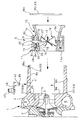
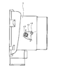
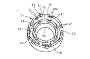
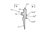
- FIG. 3 is a plan view of FIG. 2 viewed from the III-III direction. It is a side view which shows the state which assembled the guide vane unit. It is the perspective view which looked at the bearing ring from the upper part. It is a cutting side view showing an example of a guide vane. It is the top view which looked at the guide vane of Drawing 5A from the VV direction. It is a front view of a ring gear.
- FIG. 6B is a cross-sectional view of the ring gear of FIG. 6A viewed from the VI-VI direction.
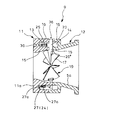
- a compressor impeller 3 is provided in the housing 2 of the compressor 1 shown in FIGS. 1 to 3, and the compressor impeller 3 is rotated by a rotating shaft 4 coaxial with a turbine impeller (not shown) that is rotated by exhaust of an automobile engine. Is done. Inside the housing 2 is formed a suction port 5 extending from the outer periphery of the compressor impeller 3 in a direction away from the compressor impeller 3, and the air whose speed has been increased by the compressor impeller 3 is used as pressure. Instead, a diffuser 7 that leads to the scroll 6 inside the housing 2 is formed.
- a cylindrical step portion 8 that is expanded from the suction port 5 and extends in a direction away from the compressor impeller 3 is provided.
- the step portion 8 includes a notch bottom surface 8a and a notch inner peripheral surface 8b.
- a guide vane unit 9 is fitted to the notch inner peripheral surface 8 b of the step portion 8, and an extension portion 5 a of the suction port 5 is formed on the inner surface of the guide vane unit 9.
- the guide vane unit 9 has a rear surface with respect to the air intake direction of the compressor impeller 3 by opposed surfaces 10a and 10b in a direction intersecting (orthogonal) with respect to the axis of the guide vane unit 9.
- the bearing ring 11 is divided into a holding ring 12 on the front side with respect to the air intake direction.
- annular grooves 13 and 14 are formed on the opposing surfaces 10 a and 10 b of the bearing ring 11 and the presser ring 12, respectively.
- the inner side wall 15 and the outer side wall 16 are formed on the opposing surfaces 10a and 10b of the bearing ring 11 and the presser ring 12 by the annular grooves 13 and 14, respectively.
- the opposed surfaces 10a and 10b of the inner wall 15 and the outer wall 16 are provided with shafts 20 and 20 'of a guide vane 19 having a blade portion 17 and a pinion 18 as shown in FIGS. 5A and 5B.
- a plurality of bearing recesses 21 to be accommodated are formed.
- the bearing recesses 21 are radially formed so as to extend in the circumferential direction at equal intervals and in the radial direction.
- 4A and 4B show a case where a U-shaped bearing recess 21 having a depth capable of accommodating the shafts 20 and 20 ′ of the guide vane 19 is formed on the facing surface 10 a of the bearing ring 11.
- the facing surface 10b of the presser ring 12 facing the bearing recess 21 provided in the bearing ring 11 is a flat surface.
- the shaft 20 outside the guide vane 19 in FIG. 5A is fitted into a bearing recess 21 provided in the outer wall 16, and the shaft 20 ′ inside the guide vane 19 is fitted into the bearing recess 21 provided in the inner wall 15.
- the shaft 20 ′ inside the guide vane 19 includes protrusions 20 a ′ and 20 b ′ that restrain the guide vane 19 from moving in the axial direction by sandwiching the inner wall 15.
- a U-shaped bearing recess 21 may be provided on the facing surface 10 b of the presser ring 12. Further, a semicircular bearing recess 21 may be formed on both the facing surface 10 a of the bearing ring 11 and the facing surface 10 b of the holding ring 12.
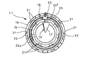
- the opposing surfaces 10a and 10b of the outer wall 16 of the bearing ring 11 and the presser ring 12 are fitted to each other so that the engaging convex part 22 and the engaging concave part 23 for positioning the bearing ring 11 and the presser ring 12 are engaged.
- engagement recesses 23 are formed at three locations on the facing surface 10a of the outer wall 16 of the bearing ring 11, and the engagement recesses 23 are fitted on the facing surface 10b of the outer wall 16 of the presser ring 12.
- Three engagement convex portions 22 are formed.
- a ring gear 25 is inserted into one of the annular grooves 13 and 14 via the pressing means 24. 4A and 4B, a pressing means 24 and a ring gear 25 are inserted into the bottom of the annular groove 13 of the bearing ring 11 having a U-shaped bearing recess 21.
- the pressing means 24 and the ring gear 25 are inserted into the annular groove 14 of the retaining ring 12.
- the semicircular bearing recess 21 is formed on both the facing surface 10a of the bearing ring 11 and the facing surface 10b of the holding ring 12, the pressing means 24 and the ring gear 25 are provided in one of the annular grooves 13 and 14. Insert.
- the ring gear 25 has gear teeth 25a formed on a short cylindrical end face.
- the gear teeth 25a of the ring gear 25 are connected to the pinion 18 of the guide vane 19 fitted in the bearing recess 21.
- Mesh. 6A and 6B shows the case where the gear teeth 25a are formed over the entire circumference, the gear teeth 25a may be formed only in the portion where the pinion 18 of the guide vane 19 meshes.
- the pinion 18 provided on the shaft 20 of the guide vane 19 in FIGS. 5A and 5B shows the case of the sector pinion provided only in the range in which the guide vane 19 rotates in the circumferential direction of the shaft 20.
- a disc-shaped pinion 18 having teeth on the entire circumference may be provided.
- the pressing means 24 securely engages the ring gear 25 with the pinion 18 of the guide vane 19.
- a wave washer 26 formed in an annular shape as shown in FIGS. 7A and 7B can be used. As shown in FIG. 7B, the wave washer 26 has a wavy shape that protrudes and dents at two locations along the circumferential direction. The wave washer 26 is pushed onto the ring gear 25 to engage the ring gear 25 with the pinion 18 of the guide vane 19.
- a coil spring 27 as shown in FIG. 8 can be used instead of the wave washer 26. When the coil spring 27 is used, it is preferable to provide a groove 27 a for positioning the coil spring 27 on the bottom surface of the annular groove 13 and the rear end surface of the ring gear 25.
- a pin 28 is inserted into the rear end surface 11 a of the bearing ring 11 and the notch bottom surface 8 a of the step portion 8 of the housing 2 to connect the bearing ring 11 (guide vane unit 9) and the housing 2. Pin holes 29 and 30 for positioning in the rotational direction are formed.
- the guide vane unit 9 has temporary fixing means for holding the bearing ring 11 and the presser ring 12 together when assembled.
- the temporary fixing means can be achieved, for example, by causing the engaging convex portion 22 and the engaging concave portion 23 included in the bearing ring 11 and the pressing ring 12 to be plastically deformed and tightly fitted. It can also be achieved by fitting and bonding between the engaging convex portion 22 and the engaging concave portion 23 with a small amount of adhesive.
- pin holes 31 are provided in the opposing surfaces 10a and 10b of the bearing ring 11 and the presser ring 12, and pins 32 that fit tightly into the pin holes 31 are inserted.
- the temporary fixing means holds the assembled guide vane unit 9 so as not to be disassembled when the guide vane unit 9 is inserted into the stepped portion 8 of the housing 2, and high strength is not required.
- the guide vane unit 9 is fixed to the step portion 8 of the housing 2 by the fixing means 33.
- an annular locking groove 34 is formed in the notch inner peripheral surface 8 b at a position corresponding to the front end surface of the guide vane unit 9 inserted in the step portion 8.
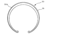
- a retaining ring 35 (fixing means 33) made of an elastic material (spring material) shown in FIG. The retaining ring 35 is inserted into the locking groove 34 in a contracted state, and is engaged with the locking groove 34 by releasing the elastic force.
- an inclined surface 35a inclined rearward from the inner side in the radial direction is formed, and on the front side surface of the retaining ring 35, an inclined surface coinciding with the inclined surface 35a is formed. 35b is formed. Therefore, when the retaining ring 35 is engaged with the retaining groove 34, the retaining ring 35 expands in diameter and moves backward (to the guide vane unit 2 side) by the action of the inclined surfaces 35a, 35b. Accordingly, the retaining ring 35 urges the guide vane unit 2 to be pushed into the inner part of the step portion 8, and the guide vane unit 2 is fixed to the step portion 8.
- a fitting portion 37 (fixing means) for tightly fitting and fixing the guide vane unit 9 to the position of the notch inner peripheral surface 8b close to the notch bottom surface 8a of the step portion 8 is shown. 33) is formed.
- the fixing means 33 by the fitting part 37 comprises the unevenness
- the notch inner peripheral surface 8 b ahead of the fitting portion 37 has a larger diameter than the fitting portion 37. For this reason, a gap 38 is provided between the notch inner peripheral surface 8 b and the outer peripheral surface of the guide vane unit 9.
- one of the retaining ring 35 and the fitting portion 37 may be provided, or both of them may be provided.
- the fixing means 33 may be a fixing bolt that fixes the guide vane unit 9 to the housing 2 so that the guide vane unit 9 does not come out of the stepped portion 8. Further, the fixing means 33 may be a small amount of adhesive used between the guide vane unit 9 and the step portion 8. In this case, since the guide vane unit 9 is fitted to the step portion 8 and bonded by an adhesive, the guide vane unit 9 is fixed to the step portion 8.
- a connection convex portion 36 is formed at the end of the shaft 20 outside the guide vane 19 so that only the center in the diameter direction protrudes.
- the tip of the connection projection 36 is the tip of the housing 2.
- the length of the step portion 8 is not in contact with the notch inner peripheral surface 8b.
- the tip of the connection convex portion 36 has a length protruding into the gap 38.
- the tip of the connecting projection 36 of the guide vane 19 may have a length that fits within the outer diameter of the guide vane unit 9. In this case, the notch inner peripheral surface 8 b and the guide vane unit are not provided without providing a gap 38. 9 may be fixed by shrink fitting.
- one of the shafts 20 of the guide vane 19 corresponds to the position of the housing 2.
- One shaft hole 41 is provided for insertion.
- a connecting recess 39 that fits into a connecting protrusion 36 provided on the shaft 20 of the guide vane 19 is provided at the tip of the rotating shaft 40.
- an operation pin 43 parallel to the rotation shaft 40 is attached to the other end of the rotation shaft 40 in a crank shape via an arm 42.
- the structural member including the housing 2, the bearing ring 11, the presser ring 12, the ring gear 25, and the guide vane 19 can be manufactured using sintered metal, aluminum die casting, resin, or the like.
- a constituent member is manufactured from a resin, it can be manufactured relatively easily and inexpensively, and the weight can be reduced.
- the assembly of the guide vane unit 9 can be performed outside the housing 2.
- the bearing ring 11 is placed on a desk or the like so that the bearing recess 21 faces upward.
- the shaft 20 outside the guide vane 19 is fitted into the bearing recess 21 provided on the facing surface 10 a of the outer wall 16 of the bearing ring 11, and is provided on the facing surface 10 a of the inner wall 15.
- the guide vane 19 is arranged so that the shaft 20 ′ inside the guide vane 19 is fitted in the bearing recess 21 formed.
- the pinion 18 of the guide vane 19 is engaged with the gear teeth 25a of the ring gear 25, and the blade portion 17 of the guide vane 19 is adjusted to have a predetermined inclination.
- the shafts 20 and 20 ′ of other guide vanes 19 are also fitted and arranged in another bearing recess 21 in FIG. 10.
- the inclination of the blade portion 17 of another guide vane 19 is adjusted to be equal to the inclination of the blade portion 17 of the guide vane 19.
- the meshing between the gear teeth 25a of the ring gear 25 and the pinion 18 of the guide vane 19 is set in advance, when the guide vane 19 is arranged at the correct position, the inclination of the blade portion 17 of each guide vane 19 is the same.
- the gear teeth 25a and the pinion 18 of the guide vane 19 are engaged with each other while being shifted from the normal position, the inclination of the blade portion 17 of the guide vane 19 is the inclination of the blade portion 17 of the other guide vane 19. It will be very different. Therefore, the guide vanes 19 can be easily fitted and arranged in the bearing recesses 21 so that the inclinations of the blade portions 17 of the guide vanes 19 are the same for all the bearing recesses 21.
- the opposing surface 10b of the presser ring 12 is opposed to the upper portion of the opposing surface 10a of the bearing ring 11, and the engaging convex portion 22 and the engaging concave portion 23 provided therebetween are fitted.
- the guide vane unit 9 is assembled by bringing the opposing surfaces 10a and 10b into contact with each other.
- the guide vane unit 9 when the guide vane unit 9 is assembled, it is assembled through a temporary fixing means for holding the bearing ring 11 and the presser ring 12 together.
- the bearing ring 11 and the presser ring 12 are assembled by inserting and assembling a pin 32 that fits tightly into the pin holes 31 provided on the opposing surfaces 10a and 10b of the bearing ring 11 and the presser ring 12. Are held together.
- the bearing ring 11 and the presser ring 12 can be held together by causing the engaging convex portion 22 and the engaging concave portion 23 provided in the bearing ring 11 and the presser ring 12 to be plastically deformed and tightly fitted.
- the bearing ring 11 and the presser ring 12 are integrally held by fitting the engaging convex portion 22 and the engaging concave portion 23 with a small amount of adhesive.
- the pinion 18 of the guide vane 19 is in a state of elastically pressing the wave washer 26 via the ring gear 25, so that the ring gear 25 and the pinion 18 are securely connected. Is kept in mesh.
- the guide vane unit 9 assembled as described above is inserted into the step portion 8 of the housing 2.
- the guide vane unit 9 is fitted into the fitting portion 37 by matching the pin 28 fixed to the rear end surface 11 a of the bearing ring 11 with the pin hole 29 formed in the notched bottom surface 8 a of the step portion 8 of the housing 2.
- the rotational position of the guide vane unit 9 with respect to the housing 2 is defined by a pin 28, and the shaft 20 of the blade portion 17 of one guide vane 19 coincides with a shaft hole 41 formed in the housing 2.
- the guide vane unit 9 is fixed to the step portion 8 of the housing 2 by the fixing means 33.
- the guide vane unit 9 When the housing 2 and the guide vane unit 9 are made of metal such as sintered metal or aluminum die casting, the guide vane unit 9 is fitted to the fitting portion 37 of the housing 2 in a state where the housing 2 is heated. This can be fixed by shrink fitting. Therefore, the fitting part 37 forms the fixing means 33 as an inlay.
- the housing 2 and the guide vane unit 9 are made of resin or the like, the housing 2 and the guide vane unit 9 may be fixed using a small amount of adhesive.
- the retaining ring 35 (fixing means 33) shown in FIG. 9 is inserted into the annular retaining groove 34 formed in the notch inner peripheral surface 8b in a contracted state and opened to release the retaining ring 35 by the resilience.
- the retaining ring 35 engaged with the locking groove 34 is enlarged in diameter and moved rearward (inner side of the step portion 8) by the action of the inclined surfaces 35a and 35b. Accordingly, the retaining ring 35 urges the guide vane unit 2 to be pushed into the inner back portion of the step portion 8 to fix the guide vane unit 2 to the step portion 8.
- the rotation shaft 40 is inserted from the shaft hole 41 provided in the housing 2, and the connection concave portion 39 provided at the tip of the rotation shaft 40 is fitted into the connection convex portion 36 of the shaft 20 of the guide vane 19. Thereby, the compressor 1 is assembled.
- the guide vane unit 9 including the plurality of guide vanes 19 and the ring gear 25 for rotating the guide vanes 19 at the same time can be assembled outside the housing 2. Therefore, even the small compressor 1 can be easily and efficiently assembled.
- a mechanism for rotating the guide vanes 19 all at once is constituted by a pinion 18 provided on the guide vane 19 and a ring gear 25 meshing with the pinion 18. Therefore, the structure is simple and the assembly is further facilitated, and the problem of causing an error in the rotation of the guide vane 19 can be prevented.
- the assembly of the turbocharger provided with the compressor 1 is improved, so that the production amount of the turbocharger and the cost can be reduced.
- the compressor of the present invention and the supercharger equipped with the compressor are not limited to the above-described embodiments, and various modifications may be made without departing from the scope of the present invention.
- a guide vane unit including a plurality of guide vanes and a mechanism for rotating each guide vane at the same time outside the housing.
Landscapes
- Engineering & Computer Science (AREA)
- Mechanical Engineering (AREA)
- General Engineering & Computer Science (AREA)
- Structures Of Non-Positive Displacement Pumps (AREA)
- Supercharger (AREA)
Abstract
組み立ての作業性を大幅に高めた圧縮機を提供する。 コンプレッサインペラ(3)と、複数のガイドベーン(19)と、複数のガイドベーン(19)を収容するガイドベーンユニット(9)と、コンプレッサインペラ(3)とガイドベーンユニット(9)とを内部に収容するハウジング(2)と、を備えた圧縮機(1)であって、ガイドベーンユニット(9)は、対向面によって前後に分割された軸受リング(11)と、押えリング(12)と、から構成され、環状溝(13,14)と、周方向に等間隔で半径方向に延びて配置される複数のガイドベーン(19)の軸(20,20')を収容する複数の軸受凹部(21)と、が軸受リング(11)と押えリング(12)の対向面の少なくとも一方に形成され、環状溝(13,14)には、軸(20,20')に設けられたピニオン(18)と噛合するリングギア(25)が配置される。
Description
本発明は圧縮機、特に可変ガイドベーンを備えた圧縮機及び前記圧縮機を備えた過給機に関する。
従来、エンジンへの過給を行う過給機は、タービンインペラとコンプレッサインペラを同軸上に備え、エンジンの排気によりタービンインペラを回転し、回転軸を介してコンプレッサインペラを回転することにより、吸気を取り入れて圧縮し得られた圧縮空気をエンジンに供給する遠心圧縮機(圧縮機)を備えている。
上記したような過給機で用いる圧縮機においては、圧縮機に取り入れる空気量が減少してくると、圧縮機の特性曲線がサージ線を越えてサージング領域に入るという特性がある。従って、上記サージ線を低流量側へ移動させてサージング領域を狭めることができれば、エンジンの運転範囲を広げることができて有益となる。
このため、従来、サージング領域に入るような低流量容量の運転状況下でも、サージング領域に入らないようにサージ線を低流量側へ移動させるようにした圧縮機としては、コンプレッサインペラの入口上流側に可変ガイドベーン(VIGV=以下、単にガイドベーンと略称する)を設けて、コンプレッサインペラに向かう空気の傾きを調整するようにしたものが提案されている(特許文献1、2参照)。
特許文献1では、コンプレッサインペラに空気を導く空気入口管(ハウジング)内側の周方向には複数のガイドベーンが放射状に配置されており、各ガイドベーンの各軸はハウジングを貫通して外部に導かれている。ハウジングの外部には前記各軸に対応して回転駆動装置を設けている。各回転駆動装置は前記各軸を同時に回転することで各ガイドベーンの回動角度を一斉に調整する。
一方、特許文献2では、コンプレッサインペラに空気を導くハウジング内側の周方向には複数のガイドベーンが放射状に配置されており、前記各ガイドベーンの各軸はハウジングの内部に設けた空間に導かれ、前記空間内部におけるガイドベーンの各軸には軸と直交方向に延びる第一のアームが取り付けられ、前記第一のアームの端部は第二のアームを介してリングに接続している。各ガイドベーンの1つの軸に接続された回転軸がハウジングを貫通して外部に導かれている。前記回動軸を回動させると、前記第一のアームと前記第二のアームを介してリングが回転し、リングが回転すると前記第二のアームと前記第一のアームを介して前記各軸が同時に回動して各ガイドベーンの回動角度が一斉に調整される。
上記した特許文献1に記載の圧縮機においては、ガイドベーンの各軸をハウジングを貫通して外部に導き、各軸に対応して設けた回転駆動装置が各軸を別個に回転駆動するようにしているので、ハウジング内部の構成は比較的簡単となる。
しかし、特許文献1では、複数のガイドベーンの各軸に対応した複数の回転駆動装置をハウジングの外部に備える必要があるため、ハウジング外部の構造が複雑となり、しかも複数の回転駆動装置を備えることにより装置価格が増加する可能性がある。又、ハウジングの外部に複数の回転駆動装置が設置されると、外部からの衝撃等により回転駆動装置が損傷する可能性が高まる。更に、前記複数の回転駆動装置を同期して運転するための制御が必要になる可能性がある。
一方、特許文献2に記載の圧縮機では、ハウジングに設けた空間に、リングと、ガイドベーンの各軸との間を接続するための前記第一のアーム及び前記第二のアームを備え、ガイドベーンの1つの軸を回動軸としてハウジングの外部に導いている。従って、この回動軸を回動させるための1つの駆動装置を備えることで、全てのガイドベーンの回動角度を一斉に調整できる利点があり、ハウジング外部の構成を簡略化することができる。
しかし、特許文献2では、ガイドベーンの各軸とリングとの間に設けられる前記第一のアーム及び前記第二のアームを、狭い空間内部で接続する必要があり、組立作業が非常に困難である。又、軸とリングとの間の力の伝達を前記第一のアーム及び前記第二のアームを介して行う構成では、各部の製作精度のバラツキ等によって各ガイドベーンの回動に誤差を生じる可能性がある。
又、特許文献2には説明されていないが、ガイドベーンの各軸はハウジングの空間を形成する内壁の孔を貫通し、この孔の軸受によって回動可能に支持する必要がある。しかしながら、前記したように軸に予めアームが備えられている場合には、前記アームが障害となって軸を内壁の孔に貫通させることができない。
このような組立性の問題を解消するためには、前記ガイドベーンの各軸をハウジングの外部に導き、この各軸を一斉に回動させるための回動リング機構をハウジングの外部に設けることも考えられる。しかし、このようにハウジングの外部に回動リング機構を設けた場合には、圧縮機の外形形状が大型化すると共に、外部からの衝撃等によって回動リング機構が損傷する可能性が高まる。
従って、上記観点から、圧縮機のガイドベーンを一斉に回動するための機構はハウジング内部に設けられることが好ましい。しかしながら、一斉に回動させるための機構をハウジング内に設けた場合には、組み立て等の作業性が非常に低下する可能性がある。特に、車載用の過給機に備えられる圧縮機は、近年、小型・軽量化が進められている。そのため、このような小型の圧縮機においては、組み立て作業性に優れた技術の出現が望まれている。
本発明は、上記事情に鑑みてなしたもので、組み立て作業性に優れた圧縮機及び前記圧縮機を備えた過給機を提供する。
本発明に係る第一の態様は、コンプレッサインペラと、羽根部とピニオンを備えた軸とを有する複数のガイドベーンと、前記複数のガイドベーンを収容するガイドベーンユニットと、前記コンプレッサインペラと前記ガイドベーンユニットとを内部に収容するハウジングと、を備えた圧縮機であって、前記ハウジングは、前記コンプレッサインペラの外周部に連通する吸込口を備え、前記吸込口から拡径されて前記コンプレッサインペラと離反する方向へ延びる円筒状の段部が形成され、前記ガイドベーンの軸の1つに外部から回動軸を挿入して接続する軸孔が形成され、前記ガイドベーンユニットは、対向面によって前後に分割された軸受リングと、押えリングと、から構成され、前記ガイドベーンユニットは、前記段部に嵌合し、固定手段によって前記段部に固定され、環状溝と、周方向に等間隔で半径方向に延びて配置される前記複数のガイドベーンの軸を収容する複数の軸受凹部と、が前記軸受リングと押えリングの対向面の少なくとも一方に形成され、前記環状溝には、前記ピニオンと噛合するリングギアが配置された圧縮機である。
本発明に係る第二の態様は、前記第一の態様において、前記軸受リングと押えリングの対向面に、互に嵌合して前記軸受リングと押えリングの位置決めを行うための凸部と凹部を備える圧縮機である。
本発明に係る第三の態様は、前記第一又は第二の態様において、前記軸受リングの後端面とハウジングの段部の底面に、ピンを挿入して前記軸受リングとハウジングの回転方向の位置決めを行うためのピン孔を備える圧縮機である。
本発明に係る第四の態様は、前記第一から第三のいずれか一つの態様において、前記環状溝の底部に、前記リングギヤを前記各ガイドベーンのピニオンに押し付けるための押付手段を備える圧縮機である。
本発明に係る第五の態様は、前記第一から第四のいずれか一つの態様において、前記ガイドベーンユニットを組み立てた際に軸受リングと押えリングを一体に保持しておくための仮止め手段を有する圧縮機である。
本発明に係る第六の態様は、前記第一から第五のいずれか一つの態様において、前記軸受凹部に嵌合した各ガイドベーンの各軸の端部には前記段部の内面に接しない長さで接続凸部が形成してあり、前記軸孔から挿入する回動軸に備えた接続凹部が前記ガイドベーンの軸の接続凸部に嵌合する圧縮機である。
本発明に係る第七の態様は、前記第一から第六のいずれか一つの態様の圧縮機を備える過給機である。
本発明によれば、複数のガイドベーンと各ガイドベーンを一斉に回動するための機構を備えたガイドベーンユニットをハウジングの外部で組み立てることができる。そのため、圧縮機の組み立ての作業性を大幅に高められるという優れた効果を奏する。
以下、本発明の実施の形態を図示例と共に説明する。
図1~図3を用いて、自動車用エンジンに備えられる過給機の圧縮機に適用した実施例を説明する。図1~図3に示す圧縮機1のハウジング2の内部にはコンプレッサインペラ3が備えてあり、コンプレッサインペラ3は、自動車用エンジンの排気によって回転する図示しないタービンインペラと同軸の回転軸4によって回転される。ハウジング2の内側には、コンプレッサインペラ3の外周部からコンプレッサインペラ3に対して離反する方向へ延びた吸込口5が形成されており、又、コンプレッサインペラ3によって速度が高められた空気を圧力に換えてハウジング2内部のスクロール6に導くディフューザ7が形成されている。
圧縮機1のハウジング2の内部には、吸込口5から拡径されてコンプレッサインペラ3に対して離反する方向へ延びる円筒状の段部8を設ける。この段部8は切欠底面8aと切欠内周面8bとからなる。一方、段部8の切欠内周面8bにはガイドベーンユニット9が嵌合しており、ガイドベーンユニット9の内面には吸込口5の延長部5aが形成されている。
ガイドベーンユニット9は、図4Aにも示すように、ガイドベーンユニット9の軸線に対して交差(直交)する方向の対向面10a,10bによって、コンプレッサインペラ3の空気取り入れ方向に対して後側の軸受リング11と、空気取り入れ方向に対して前側の押えリング12とに分割されている。軸受リング11と押えリング12の対向面10a,10bの夫々には、図4Bにも示すように、環状溝13,14が形成されている。従って、環状溝13,14によって、軸受リング11と押えリング12の対向面10a,10bには夫々内側壁15と外側壁16が形成されている。
図4A,図4Bの内側壁15と外側壁16の対向面10a,10bには、図5A,図5Bに示すように羽根部17とピニオン18を備えたガイドベーン19の軸20,20'を収容する複数の軸受凹部21を形成している。軸受凹部21は周方向に等間隔で且つ半径方向に延びるように放射状に形成されている。図4A,図4Bでは、軸受リング11の対向面10aにガイドベーン19の軸20,20’を収容できる深さのU字状の軸受凹部21を形成した場合を示している。軸受リング11に備えた軸受凹部21に対向する押えリング12の対向面10bは平坦面となっている。図5Aのガイドベーン19の外側の軸20は外側壁16に備えた軸受凹部21に嵌合し、ガイドベーン19の内側の軸20'は内側壁15に備えた軸受凹部21に嵌合する。ガイドベーン19の内側の軸20'は、内側壁15を挟むことによってガイドベーン19が軸方向へ移動するのを拘束する突部20a',20b'を備えている。尚、U字状の軸受凹部21を押えリング12の対向面10bに設けてもよい。又、軸受リング11の対向面10aと押えリング12の対向面10bの両方に半円形状の軸受凹部21を形成してもよい。
更に、軸受リング11と押えリング12の外側壁16の対向面10a,10bは、互に嵌合して軸受リング11と押えリング12の位置決めを行うための係合凸部22と係合凹部23を備えている。図4A,図4Bでは軸受リング11の外側壁16の対向面10aの3個所に係合凹部23が形成され、押えリング12の外側壁16の対向面10bには係合凹部23に嵌合する3個の係合凸部22が形成されている。係合凸部22と係合凹部23が嵌合することによって、軸受リング11と押えリング12は回転方向と半径方向への移動が拘束される。尚、軸受リング11の対向面10aに係合凸部22を設け、押えリング12の対向面10bに係合凹部23を設けてもよい。
環状溝13,14の一方には、押付手段24を介してリングギヤ25を挿入する。図4A,図4Bの例では、U字状の軸受凹部21を備えた軸受リング11の環状溝13の底部に、押付手段24とリングギヤ25を挿入している。ここで、前記とは反対に、押えリング12にU字状の軸受凹部21を備えた場合には、押えリング12の環状溝14に押付手段24とリングギヤ25を挿入する。又、軸受リング11の対向面10aと押えリング12の対向面10bの両方に半円形状の軸受凹部21を形成した場合には、環状溝13,14のいずれか一方に押付手段24とリングギヤ25を挿入する。
リングギヤ25は、図6A,図6Bに示すように、短い筒状の端面にギヤ歯25aが形成してあり、リングギヤ25のギヤ歯25aは軸受凹部21に嵌合したガイドベーン19のピニオン18と噛合する。図6A,図6Bのリングギヤ25は全周に亘ってギヤ歯25aを形成した場合を示しているが、ガイドベーン19のピニオン18が噛合する部分のみにギヤ歯25aを形成してもよい。又、図5A,図5Bのガイドベーン19の軸20に備えたピニオン18は軸20の周方向におけるガイドベーン19が回動する範囲内のみに設けられたセクターピニオンの場合を示しているが、全周に歯を有する円板状のピニオン18を備えてもよい。
押付手段24はリングギヤ25をガイドベーン19のピニオン18に確実に噛合させる。押付手段24には、図7A,図7Bに示すように環状に形成された波ワッシャ26を用いることができる。この波ワッシャ26は図7Bに示すように、周方向に沿って2個所で突出及びへこむように波打った形状を有している。波ワッシャ26をリングギヤ25に押してリングギヤ25をガイドベーン19のピニオン18に噛合させる。尚、押付手段24としては、波ワッシャ26に代えて、図8に示すようなコイルバネ27を用いることができる。コイルバネ27を用いる場合は、環状溝13の底面とリングギヤ25の後端面とに、コイルバネ27を位置決めするための溝27a等を設けることが好ましい。
図1、図2に示す如く、軸受リング11の後端面11aとハウジング2の段部8の切欠底面8aには、ピン28を挿入して軸受リング11(ガイドベーンユニット9)とハウジング2との回転方向の位置決めを行うためのピン孔29,30が形成されている。
ガイドベーンユニット9は、軸受リング11と押えリング12を組み立てた際に一体に保持しておくための仮止め手段を有している。仮止め手段は、例えば軸受リング11と押えリング12とが備える係合凸部22と係合凹部23が塑性変形を起こしてきつく嵌合させることで達成することができる。又、係合凸部22と係合凹部23との間に少量の接着剤を用いて嵌合し接着させることでも達成できる。更に、図4Bに示すように、軸受リング11と押えリング12の対向面10a,10bにピン孔31(図示では2個)を設けておき、このピン孔31にきつく嵌合するピン32を挿入することによっても、軸受リング11と押えリング12を一体に保持することができる。上記仮止め手段は、組み立てられたガイドベーンユニット9をハウジング2の段部8に挿入する際に分解しないように保持するものであり、高い強度は要求されない。
ガイドベーンユニット9は、固定手段33によってハウジング2の段部8に固定される。図1、図2では、段部8に挿入したガイドベーンユニット9の前端面に対応する位置の切欠内周面8bには環状の係止溝34が形成されている。係止溝34には、図9に示す弾性材(バネ材)からなる止め輪35(固定手段33)が配置されている。止め輪35は、縮めた状態で係止溝34に挿入し、弾撥力を開放することで係止溝34に係合する。係止溝34の前側内面には、半径方向内側から外側に向かって後方へ傾斜した傾斜面35aが形成してあり、且つ、止め輪35の前側面には、傾斜面35aと一致する傾斜面35bが形成されている。従って、係止溝34に止め輪35を係合させると、止め輪35は拡径すると共に傾斜面35a,35bの作用によって後方(ガイドベーンユニット2側)へ移動する。従って、止め輪35はガイドベーンユニット2を段部8の内奥部へ押し込むように付勢し、ガイドベーンユニット2は段部8に固定される。
図1、図2に示す如く、段部8の切欠底面8aに近い切欠内周面8bの位置には、ガイドベーンユニット9が緊密に嵌合して固定するための嵌合部37(固定手段33)が形成されている。嵌合部37による固定手段33は、焼嵌めのための凹凸(インロー)を構成する。嵌合部37よりも前方の切欠内周面8bは嵌合部37よりも大きな径を有する。このため、切欠内周面8bとガイドベーンユニット9の外周面との間には隙間38を有する。固定手段33としては、止め輪35と嵌合部37の一方を備えてもよく、又、その両方を備えてもよい。
固定手段33は、ガイドベーンユニット9が段部8から抜け出ないようにハウジング2に固定する固定ボルト等であってもよい。又、固定手段33は、ガイドベーンユニット9と段部8との間に用いられる少量の接着剤であってもよい。この場合、段部8にガイドベーンユニット9が嵌合し、接着剤によって接着されるので、段部8にガイドベーンユニット9が固定される。
図5A,図5Bに示すガイドベーン19の外側の軸20の端部には、直径方向の中心のみが突出した接続凸部36が形成されている。ガイドベーン19の軸20,20'を軸受リング11の外側壁16と内側壁15の軸受凹部21に嵌合させてガイドベーンユニット9を組み立てた際に、接続凸部36の先端はハウジング2の段部8の切欠内周面8bに接しない長さを有している。図1では、接続凸部36の先端は隙間38に突出する長さを有している。尚、ガイドベーン19の接続凸部36の先端はガイドベーンユニット9の外径内に収まる長さとしてもよく、この場合には、隙間38を設けることなく、切欠内周面8bとガイドベーンユニット9とを焼嵌めによって固定してもよい。
ハウジング2の段部8にガイドベーンユニット9を挿入した際にガイドベーン19の軸20の1つが対応するハウジング2の位置には、ガイドベーン19の軸20を回動する回動軸40を外部から挿入するための1つの軸孔41が設けられている。回動軸40の先端には、ガイドベーン19の軸20に設けられた接続凸部36に嵌合する接続凹部39が設けられている。回動軸40の他端には、図1、図3に示す如く、アーム42を介して回動軸40と平行な作動ピン43がクランク状に取り付けてある。図示しないアクチュエータによって作動ピン43が図3の矢印A方向に回動するように押し引きすると、回動軸40が回動され、接続凹部39と接続凸部36を介して1つのガイドベーン19の軸20が回動する。1つのガイドベーン19の軸20の回動はピニオン18を介してリングギヤ25に伝えられ、リングギヤ25が回転する。リングギヤ25が回転すると、ピニオン18を介して全てのガイドベーン19は一斉に回動する。
ハウジング2、軸受リング11、押えリング12、リングギヤ25及びガイドベーン19からなる構成部材は、焼結金属、アルミダイカスト、樹脂等によって製作することができる。このような構成部材を樹脂によって製作した場合には、製作が比較的容易で安価に製造することができると共に、軽量化が可能になる。
次に、上記実施例の圧縮機を組み立てる手順について説明する。
ガイドベーンユニット9の組み立ては、ハウジング2の外部において行うことができる。ガイドベーンユニット9の組み立てに当たっては、図4B、図10に示すように、軸受凹部21が上側を向くように軸受リング11を机上等に載置する。
この状態で、軸受リング11の環状溝13に、図7A,図7Bに示す波ワッシャ26を挿入し、続いて、波ワッシャ26の上側に図6A,図6Bに示すリングギヤ25を挿入する。
次に、図10に示すように、軸受リング11の外側壁16の対向面10aに備えた軸受凹部21にガイドベーン19の外側の軸20が嵌合し、内側壁15の対向面10aに設けられた軸受凹部21にガイドベーン19の内側の軸20'が嵌合するようにガイドベーン19を配置する。この時、ガイドベーン19のピニオン18がリングギヤ25のギヤ歯25aに噛合して、ガイドベーン19の羽根部17が所定の傾きになるように調整する。続いて、図10における別の軸受凹部21にも別のガイドベーン19の軸20,20'を嵌合させて配置する。この時、別のガイドベーン19の羽根部17の傾きがガイドベーン19の羽根部17の傾きと等しくなるように調整する。ここで、リングギヤ25のギヤ歯25aとガイドベーン19のピニオン18との噛み合いは予め設定されているので、正しい位置にガイドベーン19を配置すると、各ガイドベーン19の羽根部17の傾きは同じになる。そのため、ギヤ歯25aと、ガイドベーン19のピニオン18が正規の位置からずれて噛み合わされたときは、ガイドベーン19の羽根部17の傾きは、その他のガイドベーン19の羽部17の傾きとは大きく異なったものとなる。従って、全ての軸受凹部21に対し、ガイドベーン19の羽根部17の傾きが同一になるように容易且つ効率的にガイドベーン19を軸受凹部21に嵌合して配置することができる。
続いて、図4Aに示すように、軸受リング11の対向面10aの上部に押えリング12の対向面10bを対向させ、相互間に設けた係合凸部22と係合凹部23を嵌合させて対向面10a,10bを当接させることでガイドベーンユニット9を組み立てる。
尚、ガイドベーンユニット9の組み立て時には、軸受リング11と押えリング12を一体に保持しておくための仮止め手段を介して組み立てる。例えば、図4Bに示すように、軸受リング11と押えリング12の対向面10a,10bに備えたピン孔31にきつく嵌合するピン32を挿入して組み立てることにより、軸受リング11と押えリング12は一体に保持される。又、軸受リング11と押えリング12に備える係合凸部22及び係合凹部23が塑性変形を起こしてきつく嵌合させることでも軸受リング11と押えリング12は一体に保持される。又、係合凸部22と係合凹部23とを少量の接着剤を介して嵌合することでも軸受リング11と押えリング12は一体に保持される。
上記したように、軸受リング11と押えリング12を組み立てた状態では、ガイドベーン19のピニオン18がリングギヤ25を介して波ワッシャ26を弾力的に押す状態となり、これによってリングギヤ25とピニオン18は確実に噛合した状態に保たれる。
次に、図1に示すように、軸受リング11の後端面11aに設けたピン孔30にピン28を挿入した後、前記したように組み立てたガイドベーンユニット9をハウジング2の段部8に挿入する。軸受リング11の後端面11aに固定したピン28を、ハウジング2の段部8の切欠底面8aに形成したピン孔29に合致させて、ガイドベーンユニット9を嵌合部37に嵌合させる。ハウジング2に対するガイドベーンユニット9の回転方向の位置はピン28によって規定され、1つのガイドベーン19の羽根部17の軸20が、ハウジング2に形成した軸孔41に一致する。
ガイドベーンユニット9は、固定手段33によりハウジング2の段部8に固定される。
ハウジング2及びガイドベーンユニット9が、焼結金属、アルミダイカスト等の金属で製作されている場合には、ハウジング2を加熱した状態でハウジング2の嵌合部37にガイドベーンユニット9を嵌合することで焼嵌めにより固定することができる。従って、嵌合部37はインローとしての固定手段33を形成する。又、ハウジング2及びガイドベーンユニット9が、樹脂等で製作されている場合には、少量の接着材を用いてハウジング2とガイドベーンユニット9を固定してもよい。
又、切欠内周面8bに形成した環状の係止溝34に、図9に示す止め輪35(固定手段33)を縮めた状態で挿入し、開放させることで弾撥力により止め輪35を係合させる。係止溝34に係合した止め輪35は、拡径すると共に傾斜面35a,35bの作用によって後方(段部8の内奥側)へ移動する。従って、止め輪35はガイドベーンユニット2を段部8の内奥部へ押し込むように付勢して、ガイドベーンユニット2を段部8に固定する。
続いて、回動軸40をハウジング2に設けた軸孔41から挿入し、回動軸40の先端に設けた接続凹部39をガイドベーン19の軸20の接続凸部36に嵌合させる。これにより、圧縮機1は組み立てられる。
本発明の圧縮機では、前記したように、複数のガイドベーン19及び各ガイドベーン19を一斉に回動するためのリングギヤ25を備えたガイドベーンユニット9を、ハウジング2の外部において組み立てることができるので、小型の圧縮機1においても、容易且つ効率的に組み立てることができる。
更に、各ガイドベーン19を一斉に回動させるための機構が、ガイドベーン19に設けられたピニオン18とピニオン18に噛合するリングギヤ25によって構成されている。そのため、構成が簡単であり組み立てが更に容易になると共に、ガイドベーン19の回動に誤差を生じる問題を防止できる。
従って、圧縮機1を備えた過給機の組立性が向上することにより、過給機の生産量の増加及びコストの低減化が図れる。
尚、本発明の圧縮機及び前記圧縮機を備えた過給機は、上述の実施例にのみ限定されるものではなく、本発明の要旨を逸脱しない範囲内において種々変更を加えてもよい。
本発明によれば、可変ガイドベーンを備えた圧縮機及び過給機において、複数のガイドベーンと各ガイドベーンを一斉に回動するための機構を備えたガイドベーンユニットをハウジングの外部で組み立てることができる。そのため、圧縮機及び過給機の組み立ての作業性が大幅に向上する。
1 圧縮機
2 ハウジング
3 コンプレッサインペラ
5 吸込口
5a 延長部
8 段部
8a 切欠底面
8b 切欠内周面
9 ガイドベーンユニット
10a,10b 対向面
11 軸受リング
11a 後端面
12 押えリング
13,14 環状溝
15 内側壁
16 外側壁
18 ピニオン
19 ガイドベーン
20,20' 軸
21 軸受凹部
22 係合凸部
23 係合凹部
24 押付手段
25 リングギヤ
26 波ワッシャ(押付手段)
27 コイルバネ(押付手段)
28 ピン
29,30 ピン孔
31 ピン孔(仮止め手段)
32 ピン(仮止め手段)
33 固定手段
34 係止溝(固定手段)
35 止め輪(固定手段)
36 接続凸部
39 接続凹部
40 回動軸
41 軸孔
2 ハウジング
3 コンプレッサインペラ
5 吸込口
5a 延長部
8 段部
8a 切欠底面
8b 切欠内周面
9 ガイドベーンユニット
10a,10b 対向面
11 軸受リング
11a 後端面
12 押えリング
13,14 環状溝
15 内側壁
16 外側壁
18 ピニオン
19 ガイドベーン
20,20' 軸
21 軸受凹部
22 係合凸部
23 係合凹部
24 押付手段
25 リングギヤ
26 波ワッシャ(押付手段)
27 コイルバネ(押付手段)
28 ピン
29,30 ピン孔
31 ピン孔(仮止め手段)
32 ピン(仮止め手段)
33 固定手段
34 係止溝(固定手段)
35 止め輪(固定手段)
36 接続凸部
39 接続凹部
40 回動軸
41 軸孔
Claims (7)
- コンプレッサインペラと、
羽根部と、ピニオンを備えた軸と、を有する複数のガイドベーンと、
前記複数のガイドベーンを収容するガイドベーンユニットと、
前記コンプレッサインペラと、前記ガイドベーンユニットと、を内部に収容するハウジングと、を備えた圧縮機であって、
前記ハウジングは、前記コンプレッサインペラの外周部に連通する吸込口を備え、前記吸込口から拡径されて前記コンプレッサインペラと離反する方向へ延びる円筒状の段部が形成され、前記ガイドベーンの軸の1つに外部から回動軸を挿入して接続する軸孔が形成され、
前記ガイドベーンユニットは、対向面によって前後に分割された軸受リングと、押えリングと、から構成され、
前記ガイドベーンユニットは、前記段部に嵌合し、固定手段によって前記段部に固定され、
環状溝と、周方向に等間隔で半径方向に延びて配置される前記複数のガイドベーンの軸を収容する複数の軸受凹部と、が前記軸受リングと押えリングの対向面の少なくとも一方に形成され、
前記環状溝には、前記ピニオンと噛合するリングギアが配置された圧縮機。 - 前記軸受リングと押えリングの対向面に、互に嵌合して前記軸受リングと押えリングの位置決めを行う凸部と凹部を備えた請求項1に記載の圧縮機。
- 前記軸受リングの後端面とハウジングの段部の底面に、ピンを挿入して前記軸受リングとハウジングの回転方向の位置決めを行うピン孔を備えた請求項1に記載の圧縮機。
- 前記環状溝の底部に、前記リングギヤを前記各ガイドベーンのピニオンに押し付ける押付手段を備えた請求項1に記載の圧縮機。
- 前記ガイドベーンユニットを組み立てた際に軸受リングと押えリングを一体に保持する仮止め手段を有する請求項1に記載の圧縮機。
- 前記軸受凹部に嵌合した各ガイドベーンの各軸の端部には前記段部の内面に接しない長さの接続凸部が形成してあり、前記軸孔から挿入する回動軸に備えた接続凹部が前記接続凸部に嵌合する請求項1に記載の圧縮機。
- 請求項1~6のいずれか1つに記載の圧縮機を備えた過給機。
Applications Claiming Priority (2)
| Application Number | Priority Date | Filing Date | Title |
|---|---|---|---|
| JP2011-116544 | 2011-05-25 | ||
| JP2011116544A JP2012246767A (ja) | 2011-05-25 | 2011-05-25 | 圧縮機及び該圧縮機を備えた過給機 |
Publications (1)
| Publication Number | Publication Date |
|---|---|
| WO2012161283A1 true WO2012161283A1 (ja) | 2012-11-29 |
Family
ID=47217355
Family Applications (1)
| Application Number | Title | Priority Date | Filing Date |
|---|---|---|---|
| PCT/JP2012/063389 Ceased WO2012161283A1 (ja) | 2011-05-25 | 2012-05-24 | 圧縮機及び圧縮機を備えた過給機 |
Country Status (2)
| Country | Link |
|---|---|
| JP (1) | JP2012246767A (ja) |
| WO (1) | WO2012161283A1 (ja) |
Cited By (6)
| Publication number | Priority date | Publication date | Assignee | Title |
|---|---|---|---|---|
| CN107850088A (zh) * | 2015-10-26 | 2018-03-27 | 三菱重工业株式会社 | 入口导叶、压缩机、入口导叶的安装方法及离心式压缩机的制造方法 |
| CN108825533A (zh) * | 2018-06-26 | 2018-11-16 | 安徽悦达环保科技有限公司 | 一种进风口可调式风机 |
| JPWO2021070826A1 (ja) * | 2019-10-09 | 2021-04-15 | ||
| CN114033735A (zh) * | 2021-11-23 | 2022-02-11 | 湖南天雁机械有限责任公司 | 一种增压器涡轮机性能测试的调节装置及试验方法 |
| US20230304508A1 (en) * | 2022-03-24 | 2023-09-28 | Emerson Climate Technologies, Inc. | Variable inlet guide vane apparatus and compressor including same |
| US12516678B2 (en) | 2023-03-20 | 2026-01-06 | Copeland Lp | Variable inlet guide vane apparatus combined with compressor end cap |
Families Citing this family (2)
| Publication number | Priority date | Publication date | Assignee | Title |
|---|---|---|---|---|
| KR101883478B1 (ko) * | 2013-06-05 | 2018-07-30 | 한화파워시스템 주식회사 | 압축기 케이싱 |
| US10934867B2 (en) * | 2016-01-20 | 2021-03-02 | Mitsubishi Heavy Industries Engine & Turbocharger, Ltd. | Stationary-blade-type rotating machine and method for assembling stationary-blade-type rotating machine |
Citations (3)
| Publication number | Priority date | Publication date | Assignee | Title |
|---|---|---|---|---|
| JPH0250099U (ja) * | 1988-09-29 | 1990-04-06 | ||
| JPH0637501U (ja) * | 1992-10-21 | 1994-05-20 | 三菱重工業株式会社 | 静翼のシュラウド |
| US20090104022A1 (en) * | 2007-10-22 | 2009-04-23 | United Technologies Corp. | Gas Turbine Engine Systems Involving Gear-Driven Variable Vanes |
-
2011
- 2011-05-25 JP JP2011116544A patent/JP2012246767A/ja not_active Withdrawn
-
2012
- 2012-05-24 WO PCT/JP2012/063389 patent/WO2012161283A1/ja not_active Ceased
Patent Citations (3)
| Publication number | Priority date | Publication date | Assignee | Title |
|---|---|---|---|---|
| JPH0250099U (ja) * | 1988-09-29 | 1990-04-06 | ||
| JPH0637501U (ja) * | 1992-10-21 | 1994-05-20 | 三菱重工業株式会社 | 静翼のシュラウド |
| US20090104022A1 (en) * | 2007-10-22 | 2009-04-23 | United Technologies Corp. | Gas Turbine Engine Systems Involving Gear-Driven Variable Vanes |
Cited By (14)
| Publication number | Priority date | Publication date | Assignee | Title |
|---|---|---|---|---|
| CN107850088A (zh) * | 2015-10-26 | 2018-03-27 | 三菱重工业株式会社 | 入口导叶、压缩机、入口导叶的安装方法及离心式压缩机的制造方法 |
| CN108825533A (zh) * | 2018-06-26 | 2018-11-16 | 安徽悦达环保科技有限公司 | 一种进风口可调式风机 |
| JP7211529B2 (ja) | 2019-10-09 | 2023-01-24 | 株式会社Ihi | 遠心圧縮機 |
| WO2021070826A1 (ja) * | 2019-10-09 | 2021-04-15 | 株式会社Ihi | 遠心圧縮機 |
| CN113994101A (zh) * | 2019-10-09 | 2022-01-28 | 株式会社Ihi | 离心压缩机 |
| JPWO2021070826A1 (ja) * | 2019-10-09 | 2021-04-15 | ||
| US11885343B2 (en) | 2019-10-09 | 2024-01-30 | Ihi Corporation | Centrifugal compressor |
| CN113994101B (zh) * | 2019-10-09 | 2024-02-23 | 株式会社Ihi | 离心压缩机 |
| CN114033735A (zh) * | 2021-11-23 | 2022-02-11 | 湖南天雁机械有限责任公司 | 一种增压器涡轮机性能测试的调节装置及试验方法 |
| US20230304508A1 (en) * | 2022-03-24 | 2023-09-28 | Emerson Climate Technologies, Inc. | Variable inlet guide vane apparatus and compressor including same |
| US20240401608A1 (en) * | 2022-03-24 | 2024-12-05 | Copeland Lp | Variable inlet guide vane apparatus and compressor including same |
| US12180974B2 (en) * | 2022-03-24 | 2024-12-31 | Copeland Lp | Variable inlet guide vane apparatus and compressor including same |
| US12404873B2 (en) * | 2022-03-24 | 2025-09-02 | Copeland Lp | Variable inlet guide vane apparatus and compressor including same |
| US12516678B2 (en) | 2023-03-20 | 2026-01-06 | Copeland Lp | Variable inlet guide vane apparatus combined with compressor end cap |
Also Published As
| Publication number | Publication date |
|---|---|
| JP2012246767A (ja) | 2012-12-13 |
Similar Documents
| Publication | Publication Date | Title |
|---|---|---|
| WO2012161283A1 (ja) | 圧縮機及び圧縮機を備えた過給機 | |
| EP1991763B1 (en) | Variable nozzle device for a turbocharger and method of assembly thereof | |
| JP6163789B2 (ja) | 可変ノズルユニット及び可変容量型過給機 | |
| JP2013072403A (ja) | 可変容量型ターボチャージャおよび可変ノズル機構の組付方法 | |
| JP6844619B2 (ja) | 過給機 | |
| WO2015190470A1 (ja) | 可変ノズルユニット及び可変容量型過給機 | |
| JP2016148308A (ja) | 遠心圧縮機、及びギアード遠心圧縮機 | |
| US6763587B2 (en) | Manufacturing method of component part for variable capacity turbine, and the structure | |
| JP2013019304A (ja) | 圧縮機の可変ガイドベーン装置及びその組立方法並びに過給機 | |
| CN108699960B (zh) | 增压器 | |
| CN109477419B (zh) | 可变容量型增压器 | |
| JP2012052544A (ja) | ターボ機械の作動システムおよび方法 | |
| JP2013019287A (ja) | 圧縮機の可変ガイドベーン装置及びその組立方法並びに過給機 | |
| JP5365411B2 (ja) | ノズルベーン及びターボチャージャ | |
| CN109477418B (zh) | 可变容量型增压器 | |
| EP3085919A1 (en) | Variable nozzle unit and variable geometry turbocharger | |
| EP3561239B1 (en) | Wedge adapter seal | |
| JP2015052345A (ja) | フォイル軸受ユニット | |
| JP5935249B2 (ja) | 可変ガイドベーンの軸受装置及び過給機 | |
| WO2017141897A1 (ja) | ノズル駆動機構、過給機、および、可変容量型過給機 | |
| CN102859242B (zh) | 轴密封装置的制造方法、轴密封装置的制造夹具以及具备轴密封装置的回转机械 | |
| EP3650708B1 (en) | Compressor inlet adjustment mechanism | |
| JP5533060B2 (ja) | 過給機 | |
| JP5948748B2 (ja) | 可変ガイドベーン及びその製造方法並びに車両用過給機 | |
| JP2013002315A (ja) | 可変ガイドベーンの駆動機構及び過給機 |
Legal Events
| Date | Code | Title | Description |
|---|---|---|---|
| 121 | Ep: the epo has been informed by wipo that ep was designated in this application |
Ref document number: 12790147 Country of ref document: EP Kind code of ref document: A1 |
|
| NENP | Non-entry into the national phase |
Ref country code: DE |
|
| 122 | Ep: pct application non-entry in european phase |
Ref document number: 12790147 Country of ref document: EP Kind code of ref document: A1 |