WO2012160944A1 - コークス炉ガス顕熱回収装置 - Google Patents
コークス炉ガス顕熱回収装置 Download PDFInfo
- Publication number
- WO2012160944A1 WO2012160944A1 PCT/JP2012/061315 JP2012061315W WO2012160944A1 WO 2012160944 A1 WO2012160944 A1 WO 2012160944A1 JP 2012061315 W JP2012061315 W JP 2012061315W WO 2012160944 A1 WO2012160944 A1 WO 2012160944A1
- Authority
- WO
- WIPO (PCT)
- Prior art keywords
- heat
- heat exchange
- tar
- coke oven
- heat medium
- Prior art date
- Legal status (The legal status is an assumption and is not a legal conclusion. Google has not performed a legal analysis and makes no representation as to the accuracy of the status listed.)
- Ceased
Links
Images



Classifications
-
- C—CHEMISTRY; METALLURGY
- C10—PETROLEUM, GAS OR COKE INDUSTRIES; TECHNICAL GASES CONTAINING CARBON MONOXIDE; FUELS; LUBRICANTS; PEAT
- C10K—PURIFYING OR MODIFYING THE CHEMICAL COMPOSITION OF COMBUSTIBLE GASES CONTAINING CARBON MONOXIDE
- C10K1/00—Purifying combustible gases containing carbon monoxide
- C10K1/04—Purifying combustible gases containing carbon monoxide by cooling to condense non-gaseous materials
- C10K1/06—Purifying combustible gases containing carbon monoxide by cooling to condense non-gaseous materials combined with spraying with water
-
- C—CHEMISTRY; METALLURGY
- C10—PETROLEUM, GAS OR COKE INDUSTRIES; TECHNICAL GASES CONTAINING CARBON MONOXIDE; FUELS; LUBRICANTS; PEAT
- C10K—PURIFYING OR MODIFYING THE CHEMICAL COMPOSITION OF COMBUSTIBLE GASES CONTAINING CARBON MONOXIDE
- C10K1/00—Purifying combustible gases containing carbon monoxide
- C10K1/04—Purifying combustible gases containing carbon monoxide by cooling to condense non-gaseous materials
- C10K1/046—Reducing the tar content
-
- C—CHEMISTRY; METALLURGY
- C10—PETROLEUM, GAS OR COKE INDUSTRIES; TECHNICAL GASES CONTAINING CARBON MONOXIDE; FUELS; LUBRICANTS; PEAT
- C10K—PURIFYING OR MODIFYING THE CHEMICAL COMPOSITION OF COMBUSTIBLE GASES CONTAINING CARBON MONOXIDE
- C10K1/00—Purifying combustible gases containing carbon monoxide
- C10K1/08—Purifying combustible gases containing carbon monoxide by washing with liquids; Reviving the used wash liquors
- C10K1/10—Purifying combustible gases containing carbon monoxide by washing with liquids; Reviving the used wash liquors with aqueous liquids
- C10K1/12—Purifying combustible gases containing carbon monoxide by washing with liquids; Reviving the used wash liquors with aqueous liquids alkaline-reacting including the revival of the used wash liquors
- C10K1/121—Purifying combustible gases containing carbon monoxide by washing with liquids; Reviving the used wash liquors with aqueous liquids alkaline-reacting including the revival of the used wash liquors containing NH3 only (possibly in combination with NH4 salts)
-
- F—MECHANICAL ENGINEERING; LIGHTING; HEATING; WEAPONS; BLASTING
- F28—HEAT EXCHANGE IN GENERAL
- F28C—HEAT-EXCHANGE APPARATUS, NOT PROVIDED FOR IN ANOTHER SUBCLASS, IN WHICH THE HEAT-EXCHANGE MEDIA COME INTO DIRECT CONTACT WITHOUT CHEMICAL INTERACTION
- F28C3/00—Other direct-contact heat-exchange apparatus
- F28C3/06—Other direct-contact heat-exchange apparatus the heat-exchange media being a liquid and a gas or vapour
-
- Y—GENERAL TAGGING OF NEW TECHNOLOGICAL DEVELOPMENTS; GENERAL TAGGING OF CROSS-SECTIONAL TECHNOLOGIES SPANNING OVER SEVERAL SECTIONS OF THE IPC; TECHNICAL SUBJECTS COVERED BY FORMER USPC CROSS-REFERENCE ART COLLECTIONS [XRACs] AND DIGESTS
- Y02—TECHNOLOGIES OR APPLICATIONS FOR MITIGATION OR ADAPTATION AGAINST CLIMATE CHANGE
- Y02P—CLIMATE CHANGE MITIGATION TECHNOLOGIES IN THE PRODUCTION OR PROCESSING OF GOODS
- Y02P20/00—Technologies relating to chemical industry
- Y02P20/10—Process efficiency
Definitions
- the present invention relates to a coke oven gas sensible heat recovery device that recovers sensible heat of coke oven gas (COG) generated in a coke oven with high efficiency.
- COG coke oven gas
- COG In the coke production process in which coal is charged into the coking chamber of a coke oven and carbonized in a high temperature reducing atmosphere, COG of about 800 ° C is generated as a by-product. This COG is cooled to about 80 ° C. or less by receiving a cold flush in the process of passing through the riser pipe provided at the top of the coke oven, and further cooled by a gas cooler. It is separated into tar and water and recovered.
- a high boiling point tar fraction of about 150 ° C. is directly sprayed into COG to primarily cool COG to 320 to 330 ° C., and then directly contact with a medium boiling point tar fraction of about 70 ° C. And secondary cooling to about 120 ° C.
- tar is used as a heat medium, and although there is an advantage that it is not necessary to separate the heat medium and tar, the temperature of the tar after heat recovery becomes a low temperature tar with low exergy, There is a major drawback that it is no longer suitable for low pressure steam production. In addition, when it is designed to increase the tar temperature after recovery, volatilized tar appears at 200 ° C. or higher and heat recovery cannot be established.
- Non-Patent Document 1 a method for reforming volatile tar in high-temperature COG to dry gas.
- the tar content that can be dry gasified by the conventional dry gasification method is about 70% of tar (91% dry gasification), and although tar is gasified and the total calorific value of COG increases, For the 30% tar content, the sensible heat of COG after reforming (invariant before and after reforming) cannot be recovered.
- the present invention has been made in consideration of the problems in the conventional COG sensible heat recovery method as described above, and provides a coke oven gas sensible heat recovery apparatus capable of recovering heat from coke oven gas with high efficiency. Is.
- tar condenses and adheres to the surface of the heat medium that is in direct contact, but the specific gravity of tar is reduced by using an existing tar decanter (specific gravity separation tank for water, tar, and tar cake) and a heat medium recovery tank.
- tar decanter specific gravity separation tank for water, tar, and tar cake
- heat medium recovery tank By separating, tar can be prevented from being brought into a subsequent process using the heat of the heat medium.
- the heat medium it is preferable to use a low-melting-point metal, such as tin (melting point: 232 ° C., specific gravity: 7.0), which has a remarkably large specific gravity compared with tar (specific gravity of 1.1). If there is a sufficient specific gravity difference compared to tar, for example, molten salt, gallium or the like having a specific gravity of about 2 can be used.
- the direct heat exchange includes a countercurrent heat exchange in which COG and the heat medium (cooling medium) are in contact with each other and a cocurrent heat exchange in which the COG and the heat medium are in contact with each other in the same direction.
- the heat exchange by direct contact was predicted from the numerical calculation, and the basic design of the sensible heat recovery device was performed.
- the size of the direct contact heat exchange tower is ⁇ 3.6m x H10m (heat exchange effective height)
- the circulation flow rate of tin, which is the heat medium is 422kg / s (3.63 m 3 / min).
- the total power of the two pumps that circulate tin is 120 kW, and the power of the blower that draws COG that rises in the tower against the tin droplets falling in the heat exchange tower is expected to be 30 kW. Is expected to be 27.5 MW.
- the temperature of tin after heat recovery is 500 ° C.
- steam of 315 kt / year can be produced. This can reduce the amount of external fuel that is currently purchased to produce process steam, and can achieve significant cost savings even as pump and blower power charges increase. become.
- the coke oven gas sensible heat recovery apparatus of the present invention that performs heat recovery with high efficiency is a heat exchange tower that directly contacts the coke oven gas generated in the coke oven with the heat medium, and condenses tar on the surface of the heat medium.
- the gist of the present invention is to provide a heat medium recovery tank that collects the heat medium to which tar is attached, separates the tar from the heat medium by specific gravity separation, and recovers the heat medium.
- a heat medium having a heavier specific gravity than the tar can be used as the heat medium.
- a coke oven gas cooled by heat exchange in the heat exchange tower can be guided to sprinkle the water, and a non-condensed tar can be condensed and stored.
- a tar decanter that guides the aqueous water and the condensate from the aqueous water sprinkler to separate the specific gravity.
- the counter-flow coke oven gas sensible heat recovery device has a gas supply / exhaust passage for supplying the coke oven gas from the bottom of the heat exchange tower and drawing it from the top of the heat exchange tower.
- the countercurrent coke oven gas sensible heat recovery device has a passage portion for taking out a part of the heat medium to which tar has adhered to the outside of the heat exchange tower, and the heat medium recovery tank is provided at the outlet portion of the passage portion. Can be provided.
- the heat exchange tower has a droplet receiving portion for receiving the heat medium that has been subjected to heat exchange and has tar attached thereto, and the droplet receiving portion is It can be connected to the entrance of the passage.
- a second spray nozzle can be provided for spraying the heat medium separated in the heat medium recovery tank from below the droplet receiving portion.
- the cocurrent coke oven gas sensible heat recovery apparatus has a second gas supply / exhaust passage that supplies the coke oven gas from the top of the heat exchange tower and draws it from the bottom of the heat exchange tower.
- the heat medium recovery tank can be provided in the lower part of the heat exchange tower.
- the sensible heat of the high temperature coke oven gas can be recovered with high efficiency.
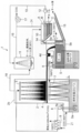
- 1 is an overall configuration diagram of a countercurrent coke oven gas sensible heat recovery apparatus according to the present invention. It is a top view which shows the structure of the basket provided in the heat exchange tower of FIG. It is a graph which shows the particle size distribution of the tin particle sprayed in a heat exchange tower. It is the graph which showed the relationship between the particle
- 1 is an overall configuration diagram of a cocurrent coke oven gas sensible heat recovery device according to the present invention. It is a graph which shows the performance prediction calculation result of the heat exchange tower in a co-current type coke oven gas sensible heat recovery apparatus.
- FIG. 1 is an overall configuration diagram of a counter-current coke oven gas sensible heat recovery device (hereinafter abbreviated as a counter-current type sensible heat recovery device) 1 according to the present invention. It is.
- FIG. 1 An 800 ° C. coke oven gas (hereinafter referred to as COG) generated from a coke oven (not shown) is introduced into the heat exchange tower 2 from the tower lower part 2a of the heat exchange tower 2. It is introduced, rises upward in the tower, and is sent out from the tower top 2b.
- COG coke oven gas
- the main components of COG are hydrogen, methane, and carbon monoxide, but other components such as tar, crude light oil, ammonia, hydrogen sulfide, and hydrogen cyanide are also included.
- the diameter of the heat exchange tower 2 in this embodiment is ⁇ 3.6 m, and the height H is 10 m. The basis of design will be described later.
- a spray mist nozzle (spray nozzle) 3 is disposed in the tower top 2b. From the spray mist nozzle 3, tin as a heating medium has an initial temperature of 250 ° C. above the melting point and an average droplet particle diameter of 1 mm. It is supposed to be sprayed with.
- Tin droplets fall in the tower, while COG flows upward in the tower, thereby forming a countercurrent direct contact heat exchange. During this time, gravity acts downward on the droplet, but it falls slowly because it receives fluid drag by the upwardly flowing COG. As a result, heat exchange can be performed for a longer time than in the case of free-falling.
- the tin particles falling in the tower are heated by contact with the high-temperature COG, whereas the COG is cooled by passing heat to the tin.
- the tar content in the COG falls below 450 ° C., it begins to condense in the heat exchange environment with the surface of the tin droplet, which is the lowest temperature, as the nucleus. Thereby, tar adheres to the surface of the tin droplet.
- the falling tar-attached tin droplets are received by the scissors 4 provided at a height of 5 m from the tin liquid surface L (0 m) and guided to the adjacent heat medium recovery tank 5.
- a plurality of openings are provided in the eaves 4 so as not to completely block the flow of COG rising in the heat exchange tower 2.
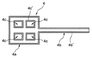
- FIG. 2 is a plan view showing the configuration of the cage 4.
- the tub 4 is a window frame-shaped droplet receiving portion 4a disposed in the horizontal direction in the heat exchange tower 2, and extends linearly from a part of the droplet receiving portion 4a and is inclined downward.
- the droplet receiving portion 4a is provided with a plurality of rectangular openings 4c.
- openings 4c are provided in order to make the closed area occupied in the horizontal section of the heat exchange tower 2 50%, leading 50% of the falling tin particles to the heat medium recovery tank 5 and the remaining 50%. Is directly dropped to the bottom of the heat exchange tower 2.
- 4b ' is a side wall forming the passage 4b
- 4c' is a side wall formed around the opening 4c.
- the opening 4c is not limited to the rectangular shape as long as the closed area can be reduced to 50%.
- the opening 4c may be formed of a punching metal having a large number of circular holes.
- the tar is discharged from the outlet 5a to the outside of the heat medium recovery tank 5 with sensible heat of about 350 ° C., and is used and processed as before after cooling.
- the tin sinking in the lower part of the heat medium recovery tank 5 is positioned at a height of 5 m in the heat exchange tower 2 from the lower part of the heat medium recovery tank 5 by the first vertical pump 6 provided in the heat medium recovery tank 5, that is, It is sent to the lower surface position of the basket 4 and sprayed again into the heat exchange tower 2 from the second spray mist nozzle (second spray nozzle) 7.
- the sprayed tin is brought into direct contact with the high-temperature COG and is heated together with the tin that directly falls through the opening 4c.
- the tin that pours into the liquid tin bath provided in the tower lower part 2a of the heat exchange tower 2 includes tin that does not contain tar that has passed through the heat medium recovery tank 5, and the opening 4c (opening ratio 50%) of the basket 4. Both tin that has fallen through the surface and has tar attached to the surface are present.
- the tar volatilizes again by the time it arrives here and rises in the heat exchange tower 2 together with the high-temperature COG. And as it rises, it cools again and condenses. As a result, the tar gas concentration in the heat exchange tower 2 is slightly increased due to the re-volatilized tar, and is stabilized to a steady state.
- the tin of the liquid tin bath is pumped up from the heat exchange tower 2 by the second vertical pump 8 and used as heat. For example, it is sent to a boiler 9 for producing low-pressure process steam and cooled to 250 ° C. higher than the melting point. And the operation
- the liquid tin and tin vapor also become solid and flow into the tar decanter 10 together with the water.
- the specific gravity is separated from the top in the order of water A, tar B, tar trough C, and the water A is re-charged through the pump 12 and the circulation path 13 except for a part that is extracted and treated with water. Water is sprayed from the water sprinkler 11.
- the tar B is discharged and used / processed, and the tar cake C is scraped and processed by the conveyor 14 as a scraping device.
- ⁇ Tar C is mainly composed of solid particles consisting of fine coal powder and fine coke powder. Solid tin with the highest specific gravity is also mixed in the tar. In order to reuse this solid tin, in this embodiment, the tar soot C containing solid tin is dumped into the heat medium recovery tank 5 as it is.
- Tar C has a specific gravity larger than that of tar and smaller than that of tin. Therefore, a layer is formed so as to be sandwiched between tar and tin.
- the solid tin contained in tar C will dissolve again in an environment of 350 ° C. It becomes liquid and merges with the tin layer stored at the bottom of the heat medium recovery tank 5.
- a shelf 5b is provided at the boundary height between tin and tar, and the tar-medium C in a solid state even at 350 ° C. is heated by the second conveyor 15 as a second scraping device by the heat medium recovery tank 5. It is trying to discharge outside.
- a float type level gauge (not shown) is used to control the first vertical pump 6 for tin feeding. This can be realized.
- the specific gravity of the float is set between tar (specific gravity 1.1) and tin (specific gravity 7), and the height of the tar-tin interface is detected with a float-type liquid level gauge. If it is higher than 5b, the rotational speed of the first saddle pump 6 is increased to increase the pump flow rate and lower the interface height. On the contrary, when the interface height is lower than the shelf 5b, the pump flow rate is reduced by decreasing the rotational speed of the first saddle pump 6 so that the interface height is increased.
- the said tar decanter 10 can use the existing thing.
- a dive weir 4d is provided in the passage portion 4b of the cage 4 so as to prevent the COG from being exhausted in the middle of heat exchange.
- the droplet receiving part 4a is connected to the inlet part of the channel
- One is a second vertical pump 8 for sending again the tin accumulated in the liquid metal bath at the lower part of the heat exchange tower 2 to the spray mist nozzle 3 at the upper part of the heat exchange tower 2, and the temperature range to be handled is 500-600. ° C.
- the other is a first vertical pump 6 that feeds the tin accumulated in the lower part of the heat medium recovery tank 5 to a second spray mist nozzle 7 installed at an intermediate height of the heat exchange tower 2, and the temperature to be handled.
- the range is around 350 ° C.
- vertical (vertical shaft) multistage pumps made by Nissan Kiko Co., Ltd. or Arai Seisakusho Co., Ltd., which put the motor part on the top outside the tank and lower the shaft vertically, are used. can do.
- This type of vertical (vertical shaft) multistage pump is also used for liquid feeding of molten metal and molten salt.
- a third chamber 16 is provided between the seal portion through which the shaft passes and the outside air, and nitrogen is applied to the third chamber 16 at a pressure higher than the pressure on the COG side. To supply. Thereby, even if there is a leak in the seal, either nitrogen is mixed into the COG side or nitrogen leaks into the outside air, so that safety is ensured.
- An example of the sealing material is Inconel fiber heat-resistant expanded graphite gland packing that can be used up to 600 ° C.
- Spray Mist Nozzle As the spray mist nozzle 3 for tin spray, a high temperature packing (for example, metal packing such as copper) that can withstand only the packing is used, and the water mist nozzle is made of tin. Can be used for spraying.
- a high temperature packing for example, metal packing such as copper
- the particle diameter produced by the same mist nozzle is almost the same for both tin and water.
- the pressure becomes 7 times depending on the density ratio (specific gravity ratio) of tin and water.
- the volume flow rate is the same for both.
- 17 is a blower connected to the safety water sprinkler 11, and when this blower 17 is driven, COG supplied to the heat exchange tower 2 rises due to the tin spray, It is discharged out of the counter-flow sensible heat recovery device 1 through the connecting pipe 18 ⁇ the water spraying device 11 ⁇ the discharge pipe 19. That is, the COG supply line 21 and the connecting pipe 18 function as a gas supply / exhaust path for supplying COG from the tower lower portion 2 a of the heat exchange tower 2 and drawing it from the tower top 2 b of the heat exchange tower 2.
- reference numeral 24 denotes a pressure equalizing pipe for equalizing the water spraying device 11 and the tar decanter 10.
- Tin dispersion As a method for evaluating the critical condition of splitting into particles during atomization, the critical Weber number We crit is used which represents the ratio of the drag force received from the fluid to the surface tension force.
- equation (2-2) is proposed as a correction equation for equation (2-1).
- W dot e crit is the critical Weber number when the viscosity of the fluid is zero. That is, in general, the atomized particle diameter is expressed by a function of the Weber number We and the Onesorge number Oh.
- Table 1 shows the physical property values of tin and water, the Reynolds number Re, the Weber number We, and the Ohnesorge number Oh at the particle diameter and injection speed assumed for the tin mist nozzle of this time.
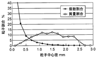
- the particle size distribution is shown in the graph of FIG.
- the graph shows the expected particle size distribution of tin with the selected mist nozzle.
- the number ratio, the mass ratio, and the heat recovery ratio when sprayed in the heat exchange tower 2 for each particle diameter are shown, and the minimum particle diameter is 0.1 mm.
- Tin particles having a particle size of 0.1 mm have a terminal velocity of 2.0 m / s in a COG atmosphere at 800 ° C., so that the COG ascent rate is reduced by a slight wind so that all tin particles can fall down the heat exchange tower 2. If an attempt is made to design at about 2.0 m / s or less, the heat exchange tower 2 becomes large and is not realistic.
- the final velocity of tin particles having a particle diameter of 0.4 mm in an 800 ° C. static COG atmosphere is 11.86 m / s
- the cross-sectional area of the heat exchange tower required for this flow velocity is 10.12 m 2 ( ⁇ 3.6 m )
- a particle having a diameter of less than 0.4 mm, which is 2.9 wt% of the whole, is allowed to be discharged together with the COG, and a method of collecting at a later stage is adopted. This is why the tar decanter 10 is connected to the heat medium recovery tank 5.
- a candidate for a spray mist nozzle for spraying tin is Ikeuchi WP901000 having a fan-shaped injection angle of 90 °, a flow rate of 408 L/min@0.35 MPa (Sn), and a foreign substance passage diameter of 5.6 mm.
- m dot mass flow rate
- Cp constant pressure specific heat
- T temperature
- z vertical distance
- ⁇ thermal conductivity
- D diameter
- ⁇ density
- v speed
- A heat exchange tower cross section
- Nu Nusselt number
- subscripts represent COG: coke oven gas
- m heating medium (tin)
- i particle group number having each center diameter shown in FIG.
- Equation (3-3) The Nusselt number Nu i representing the heat transfer around the heat medium (tin) droplet assuming a spherical shape is expressed by Equation (3-3).
- Re i is the particle Reynolds number of the i-th particle
- Pr is the Prandtl number of COG.
- Equation (3-4) The equation of motion of the particle is obtained by equation (3-4) considering gravity and drag.
- g gravitational acceleration
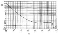
- C Di drag coefficient acting on the particle group i, which is given by the relationship between the particle Reynolds number and the drag coefficient of the sphere in FIG. 4 as a function of Re i .
- the initial velocity of the particles was determined by Bernoulli's equation from the pressure difference before and after the spray slit of the spray mist nozzle. Actually, the initial speed when tin is supplied to the mist nozzle having the characteristics shown in FIG. 3 at 0.35 MPa is estimated to be 10 m / s.
- Equation (3-5) The end velocity u mit of the particle is obtained by equation (3-5) from the balance condition between gravity and drag where the right side of equation (3-4) becomes zero.
- volume occupation ratio R occupied by the liquid metal particles in the tower can be obtained by the equation (3-8).
- the density of the COG in the heat exchange tower changes as it cools.
- the relationship between density and temperature is varied according to the ideal gas equation of state.
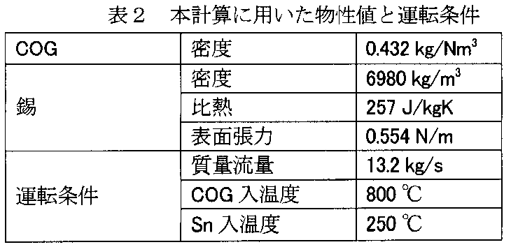
- Table 2 shows the physical property values and operating conditions used for this calculation.
- the physical property values at 250 ° C. and 800 ° C. shown in Table 3 are taken out, and a linear approximation formula is constructed and used for the change in temperature. Yes.
- Each physical property value of COG at 250 ° C and 800 ° C is the physical property value of the mixed gas having the composition of COG after purification (H 2 : 58%, CH 4 : 27%, CO: 7%, N 2 : 8%) Is substituted.
- the input power was the sum of the pump power for feeding liquid tin and the COG blower power taking into consideration the pressure loss on the piping to the heat exchange tower and the water sprinkler and the drag on the droplets.
- the combined power of the tin feed pumps is in the order of 0.25 kJ / kg-tin, and the power of the COG blower is in the order of 0.33 to 1.0 kJ / Nm 3 -COG.
- tower height 10 m and 5 m is shown in the same graph for comparison.
- the ratio of tin and COG supplied to the heat exchange tower 2 is represented by a metal / gas mass flow ratio
- the temperature of tin stored in the tower lower part 2a is represented as a liquid metal bath temperature
- the tin droplets are heated.
- the ratio occupied in the exchange tower 2 is expressed as a liquid enemy space occupation ratio.
- the COG outlet temperature gradually approaches the low temperature of the heat exchanger, that is, the temperature of the sprayed tin 250 ° C. (see L1 and L2).
- the heat exchange efficiency when the tower height is 5 m is 82%.
- the heat exchange efficiency is 95 to 96%. If an attempt is made to obtain a heat exchange efficiency equivalent to that of a tower height of 10 m at a tower height of 5 m, the metal / gas mass flow rate ratio must be significantly increased.
- the liquid metal bath temperature (see L5) will be below 500 ° C.
- L6 has shown the liquid metal bath temperature in case the tower height is 10 m.
- the blower (blower 17 of FIG. 1) is driven by the drag acting on the tin feed pump (first vertical pump 6 and second vertical pump 8 of FIG. 1) and the tin particles. ) And the recovered heat / input power ratio with a tower height of 5 m and the recovered heat / input power ratio with a tower height of 10 m both decrease.
- the space occupancy rate of liquid tin in the space in the heat exchange tower 2 is almost independent of the tower height and substantially corresponds to the metal / gas mass flow rate ratio, Moreover, it is a small value of less than 0.1%. From this calculation result, the following can be understood.
- COG outlet temperature gradually approaches a temperature of 250 ° C. on the low temperature side of the heat exchanger, and its tendency becomes vertically symmetrical with the heat exchange efficiency. If a further low melting point metal such as gallium is used as the heat medium, sufficient heat recovery can be achieved up to 250 ° C. or less.
- the scale of heat utilization equipment such as a boiler using tin as a heat medium increases.
- this temperature should increase due to increased heat recovery, but in practice the metal / gas mass flow ratio increases further, and the increase in the metal / gas mass flow ratio Thus, the temperature of the liquid metal bath tends to decrease.
- the metal / gas mass flow rate ratio is 32 (at this time when the heat exchange height is 10 m.
- the metal / gas mass flow ratio 27 (the heat exchange efficiency at this time is 82%) is the upper limit. Therefore, when the heat exchange efficiency of both is compared, it is more advantageous to adopt a heat exchange height of 10 m.
- the effective height of the heat exchange tower 2 is 10 m and the metal / gas mass flow rate ratio is 32.
- the graph of FIG. 6 shows the temperature distribution of the COG inside the heat exchange tower and the liquid metal particles of each particle size at a heat exchange tower height of 10 m and a metal / gas mass flow rate ratio of 30.6, which is almost equal to the conditions.
- the vertical axis in the graph of FIG. 6 indicates the height of the heat exchange tower 2, and 0 m corresponds to the liquid level L of tin (see FIG. 1), and 10 m corresponds to the top 2b of the tower.
- the horizontal axis indicates the temperature. It shows a case where tin having various particle diameters is injected from a height of 10 m at a temperature of 250 ° C., while COG of 800 ° C. is supplied from the lower part of the heat exchange tower 2.
- particle diameter 0.5 mm the larger the specific surface area is, so that the temperature rises quickly due to heat exchange, but as the particle diameter increases (particle diameter 2.5 mm), the temperature rise slows down.
- the cage 4 is provided at the height of 5 m of the heat exchange tower 2, and at this height of the cage 4, tin with a particle diameter of 2.5 mm rises in temperature from 250 ° C. to 290 ° C.
- the temperature of tin having a particle diameter of 0.5 mm rises to 400 ° C., and the average temperature is about 350 ° C.
- tar components having a boiling point of at least 290 ° C. such as benzo [a] pyrene and phenanthrene, can be recovered. Therefore, it is only necessary to install a grid-like ridge 4 having an aperture ratio of 50% at a position 5 m at the middle height of the heat exchange tower 2.
- FIG. 7 shows the velocity distributions of COG and liquid metal particles of various particle sizes under the same conditions.
- the vertical axis indicates the height direction position of the heat exchange tower 2, and the horizontal axis indicates the downward speed.
- tin having a small particle diameter for example, having a particle diameter of 0.5 mm, is ejected from the spray mist nozzle 3 at an initial speed of 10 m / s. It falls while being decelerated to about 5m / s.
- the particle diameter is 2.5 mm, the gravity is higher than the fluid drag, and it falls while accelerating.
- Cocurrent coke oven gas sensible heat recovery device 20 (hereinafter abbreviated as a cocurrent sensible heat recovery device) 20 shown in FIG.
- the exchange tower 2 and the heat medium recovery tank 5 are integrated.
- FIG. 8 the same constituent elements as those in FIG.
- the 800 ° C. COG is introduced into the heat exchange tower 22 from the top 22 a of the heat exchange tower 22 via the COG supply line 21, and is drawn out from the tower lower portion 22 b of the heat exchange tower 2 through the connecting pipe 18. ing.
- the COG supply line 21 and the connecting pipe 18 function as a second gas supply / exhaust path for supplying COG from the tower top 22 a of the heat exchange tower 22 and drawing it from the tower lower part 22 b of the heat exchange tower 22.
- the tar-attached tin droplets falling in the heat exchange tower 22 are received by a heat medium recovery tank 23 as a specific gravity separation tank provided in the lower part of the heat exchange tower 22, while the COG is cooled to about 320 ° C. It is sent out from the tower lower part 22b to the water sprinkler 11.
- the heat exchange tower 22 has a diameter of 3.6 m and a height H of 20 m.
- the droplet slowly falls due to the drag of the upward flowing COG, and the contact time with the droplet can be increased.
- the heat exchange efficiency is lower than that in the countercurrent direct contact heat exchange. Therefore, in the cocurrent sensible heat recovery apparatus 20, the height of the heat exchange tower 22 is increased to compensate for the decrease in heat exchange efficiency.
- a passage portion for taking out a part of the heat medium (tin droplets) condensed with tar is not provided, and all of the heat medium is removed. It is made to pour into the heat medium recovery tank 23 provided in the lower part of the heat exchange tower 22. Thereby, the spear 4, the first scissor pump 6, and the second spray nozzle 7 can be omitted, and the apparatus can be simplified.
- reference numeral 24 denotes a pressure equalizing tube.
- FIG. 9 is a graph showing the performance prediction calculation result of the heat exchange tower by the cocurrent sensible heat recovery device.
- the horizontal axis is the metal / gas mass flow ratio indicating the ratio of tin and coke oven gas supplied to the heat exchange tower 22, and the left vertical axis is the recovered heat / input power ratio and the liquid metal bath temperature ° C.
- the temperature of tin stored in the heat medium recovery tank 23 is shown, and the right vertical axis shows the heat exchange efficiency%.
- the heat medium amount flow rate is 125 times the COG mass flow rate because of cocurrent flow contact. Therefore, only 24 times heat recovery can be performed with respect to the power of the pump and the blower supplied to the cocurrent flow sensible heat recovery device 20.
- the cocurrent sensible heat recovery device 20 requires about eight times the power of the countercurrent sensible heat recovery device 1.
- the pump power is primarily larger than the blower power, and the pump power P (W) is proportional to mdot ⁇ H,
- m dot is the heat medium flow rate (kg / s)
- g is the acceleration of gravity (m / s 2 )
- H is the head (heat exchange tower height) (m)
- ⁇ is the pump efficiency.
- the parallel flow sensible heat recovery device 20 has an advantage that the facilities and the operation method can be greatly simplified.
- the operation of the first vertical pump 6 for the second spray mist nozzle 7 can be controlled so that the liquid level of the heat medium recovery tank 5 is maintained constant.
- the cocurrent flow sensible heat recovery device 20 such liquid level control is not required.
- the gutter 4 for taking out a part of the heat medium to the outside of the heat exchange tower 22 is not required, the passage portion 4b is not clogged and the maintenance is facilitated.
- COG has a sensible heat of about 800 ° C, so despite the amount of generated heat of about 0.95MJ / Nm 3 -COG, the tar condenses and adheres to the heat transfer tube when cooled to 450 ° C or below. So far, almost no heat recovery has been performed.
- tar is condensed on the surface of liquid tin by bringing tin droplets into direct contact with high-temperature COG, and then the specific gravity of tar and liquid tin is reduced. Since they are configured to be separated, if the present invention is applied to a coke oven, a significant cost reduction can be realized, and the amount of CO 2 emission can also be greatly reduced.
- the trap 4 is provided in the heat exchange tower 2 to receive the tin droplets with tar and supply it to the heat medium recovery tank 5.
- a heat medium recovery tank may be provided in the lower part of the heat exchange tower 2 without providing the tub 4. it can.
- the coke oven gas sensible heat recovery apparatus of the present invention can be used in the field of saving energy by recovering sensible heat of COG generated in a coke oven.
- Counter-current sensible heat recovery device Heat exchange tower (heat exchange device) 2a Tower lower part 2b Tower top part 3 Spattering mist nozzle (spraying nozzle) 4 ⁇ 4a Droplet receiving portion 4b Passage portion 4c Opening portion 4d Dive weir 5 Heat medium recovery tank 5a Discharge port 5b Shelf portion 6 First vertical pump 7 Second spray mist nozzle (second spray nozzle) 8 Second vertical pump 9 Boiler 10 Tar decanter 11 Aqueous water sprinkler 12 Pump 13 Circulation path 14 Conveyor 15 Second conveyor 16 Third chamber 17 Blower 18 Connection pipe 19 Discharge pipe 20 Cocurrent flow sensible heat recovery device 21 COG supply Line 22 Heat exchange tower 23 Heat medium recovery tank
Landscapes
- Chemical & Material Sciences (AREA)
- Engineering & Computer Science (AREA)
- Combustion & Propulsion (AREA)
- Chemical Kinetics & Catalysis (AREA)
- General Chemical & Material Sciences (AREA)
- Oil, Petroleum & Natural Gas (AREA)
- Organic Chemistry (AREA)
- Mechanical Engineering (AREA)
- General Engineering & Computer Science (AREA)
- Industrial Gases (AREA)
- Vaporization, Distillation, Condensation, Sublimation, And Cold Traps (AREA)
Abstract
コークス炉ガスから高効率にて熱回収を行うことができるコークス炉ガス顕熱回収装置は、コークス炉で発生するコークス炉ガスと熱媒とを直接接触させ、その熱媒の表面にタールを凝縮させる熱交換塔2と、タールが付着した上記熱媒を集合させ、比重分離によって上記熱媒からタールを分離させ、上記熱媒を回収する熱媒回収槽5とを備えていることを特徴とする。
Description
本発明は、コークス炉で発生するコークス炉ガス(COG)の顕熱を高効率で回収するコークス炉ガス顕熱回収装置に関するものである。
石炭をコークス炉の炭化室に装入し、高温還元雰囲気で乾留するコークス製造プロセスでは副産物として約800℃のCOGが発生する。このCOGは、コークス炉頂部に設けられている上昇管を通る過程で安水フラッシングを受けて約80℃以下に急激に冷却され、さらにガスクーラーで冷却された後、凝縮した液分はタールデカンターでタールと安水とに分離され、回収されるようになっている。
これまで安水フラッシングを行わずにCOGの顕熱を有効に回収しようとする方法として、直接接触法を用いたCOG顕熱回収方法が提案されている(例えば特許文献1参照)。
上記COG顕熱回収方法とは、COG中に約150℃の高沸点タール留分を直接噴霧してCOGを320~330℃まで一次冷却し、さらに約70℃の中沸点タール留分と直接接触させて約120℃まで二次冷却するというものである。
上記COG顕熱回収方法では熱媒としてタールを使用しており、熱媒とタールとを分離する必要がないという利点があるものの、熱回収後のタールの温度がエクセルギの低い低温タールになり、もはや低圧蒸気製造には適さないという大きな欠点がある。なお、この回収後のタール温度を上げるように設計した場合、200℃以上では揮発するタールが現れて熱回収が成立しなくなる。
温度が800℃から250℃まで変化するCOGから有効に熱回収ができれば0.95MJ/Nm3- COGのエネルギーの回収が見込まれる。
しかしながら、国内のコークス工場で250℃までの熱回収は行われていないのが実情である。その原因は、COGに含まれるタール分は800℃では揮発状態にあるが450℃を下回るとタール分が凝縮するため、間接熱交換式では伝熱管表面にタールが厚く凝縮して熱交換性能が低下し、一方、直接接触式では熱媒の表面にタールが付着して熱回収後のプロセスが成立しなくなるからである。
多くのCOG顕熱回収方法が提案されながら、それらの方法がほとんど実施されずにいるのは上記理由による。
そこで、最近ではタールを扱うことが困難であるとして、高温のCOG中の揮発タールを改質してドライガス化する方法へと技術開発の関心が向けられている(例えば非特許文献1参照)。
鈴木公仁、他著、高温COG中タールの触媒ドライガス化(改質・利用技術)、石炭科学会議発表論文集(45),36-37,2008-10-09
しかしながら、従来のドライガス化による方法でドライガス化できるタール分はタールの70%程度(ドライガス化91%)であり、確かにタールがガス化してCOGの総発熱量は増加するものの、残り30%のタール分については改質後COGの顕熱(改質前後で不変)は回収できていない。
本発明は以上のような従来のCOG顕熱回収方法における課題を考慮してなされたものであり、コークス炉ガスから高効率で熱回収を行うことができるコークス炉ガス顕熱回収装置を提供するものである。
コークス炉ガスの顕熱を回収するにあたり、回収装置に伝熱管を用いる間接熱交換法ではタールが付着することによって伝熱管の総括伝熱係数が低下するという問題を解決できないため、本発明では直接熱交換法を採用する。
直接熱交換法では直接接触する熱媒の表面にタールが凝縮付着するが、既存のタールデカンター(安水、タール、タール滓の比重分離槽)と熱媒回収槽を利用して、タールを比重分離することで、熱媒の熱を利用する後続のプロセスへタールを持ち込まないようにすることができる。
上記熱媒としては、タール(比重1.1)と比較して比重が顕著に大きい低融点金属、例えば錫(融点232℃、比重7.0)を使用することが好ましい。タールと比較して十分な比重差があれば、例えば、比重が2前後である溶融塩、ガリウム等を用いることもできる。
上記直接熱交換には、COGと熱媒(冷却媒体)が向かい合わせに接して流れる向流式熱交換と、COGと熱媒が同じ向きに接して流れる並流式熱交換が含まれる。
上記直接熱交換には、COGと熱媒(冷却媒体)が向かい合わせに接して流れる向流式熱交換と、COGと熱媒が同じ向きに接して流れる並流式熱交換が含まれる。
向流式熱交換によってCOGの顕熱を回収を行うにあたり、直接接触による熱交換を数値計算から予測し、顕熱回収装置の基本設計を行った。あるコークス工場のサイズ規模を例に取り設計を行うと、直接接触式熱交換塔の大きさはφ3.6m×H10m(熱交換有効高さ)となり、熱媒である錫の循環流量は422kg/s(3.63m3/min)になった。
錫を循環させる2機の送液ポンプの合計動力は120kW、熱交換塔内を落下する錫液滴に逆らって塔内を上昇するCOGを吸引する送風ブロワの動力は30kWが予想され、熱回収は27.5MWが見込まれる。
熱回収後の錫の温度は500℃になり、この熱を低圧プロセス蒸気製造として利用すると、315kt/年の蒸気を製造することができる。これにより現在、プロセス蒸気を製造するために購入している外部燃料を削減することができ、ポンプ動力とブロワ動力の電気料金が新たに増加するとしても、大幅なコストダウンを達成することが可能になる。
高効率で熱回収を行う本発明のコークス炉ガス顕熱回収装置は、コークス炉で発生するコークス炉ガスと熱媒とを直接接触させ、その熱媒の表面にタールを凝縮させる熱交換塔と、
タールが付着した上記熱媒を集合させ、比重分離によって上記熱媒からタールを分離させ、上記熱媒を回収する熱媒回収槽とを備えていることを要旨とする。
タールが付着した上記熱媒を集合させ、比重分離によって上記熱媒からタールを分離させ、上記熱媒を回収する熱媒回収槽とを備えていることを要旨とする。
本発明において、上記熱媒として上記タールよりも比重が重い熱媒を使用することができる。
本発明において、上記熱交換塔内の熱交換によって冷却されたコークス炉ガスを導いて安水を散水し、未凝縮のタール分を凝縮させ貯溜する安水散水装置を有することができる。
本発明において、上記安水散水装置からの安水と凝縮液とを導いて比重分離させるタールデカンターを有することができる。
本発明において、上記タールデカンターの最下層に沈殿した熱媒とタール滓との混合物を、上記熱媒回収槽に供給する掻出装置を有することができる。
本発明において、上記熱媒を上記熱交換塔の上部から散液する散液ノズルを有することができる。
向流式コークス炉ガス顕熱回収装置は、上記コークス炉ガスを上記熱交換塔の塔下部から供給し、上記熱交換塔の塔頂部から引き出すガス給排路を有する。
向流式コークス炉ガス顕熱回収装置では、タールが付着した上記熱媒の一部を上記熱交換塔の外部に取り出す通路部を有し、この通路部の出口部に上記熱媒回収槽を備えることができる。
向流式コークス炉ガス顕熱回収装置は、上記コークス炉ガスを上記熱交換塔の塔下部から供給し、上記熱交換塔の塔頂部から引き出すガス給排路を有する。
向流式コークス炉ガス顕熱回収装置では、タールが付着した上記熱媒の一部を上記熱交換塔の外部に取り出す通路部を有し、この通路部の出口部に上記熱媒回収槽を備えることができる。
また、向流式コークス炉ガス顕熱回収装置では、熱交換に供せられタールが付着した上記熱媒を受ける液滴受け部を上記熱交換塔内に有し、この液滴受け部を上記通路部の入口部と接続することができる。
また、向流式コークス炉ガス顕熱回収装置では、上記熱媒回収槽において分離された上記熱媒を、上記液滴受け部の下方から散液する第二散液ノズルを設けることができる。
並流式コークス炉ガス顕熱回収装置は、上記コークス炉ガスを上記熱交換塔の塔頂部から供給し、上記熱交換塔の塔下部から引き出す第二のガス給排路を有する。
並流式コークス炉ガス顕熱回収装置では、上記熱交換塔の下部に上記熱媒回収槽を設けることができる。
並流式コークス炉ガス顕熱回収装置は、上記コークス炉ガスを上記熱交換塔の塔頂部から供給し、上記熱交換塔の塔下部から引き出す第二のガス給排路を有する。
並流式コークス炉ガス顕熱回収装置では、上記熱交換塔の下部に上記熱媒回収槽を設けることができる。
本発明によれば、高温のコークス炉ガスの顕熱を高効率で回収することができるという長所を有する。
以下、図面に示した実施の形態に基づいて本発明を詳細に説明する。
[1]向流式コークス炉ガス顕熱回収装置
図1は、本発明に係る向流式コークス炉ガス顕熱回収装置(以下、向流式顕熱回収装置と略称する)1の全体構成図である。
図1は、本発明に係る向流式コークス炉ガス顕熱回収装置(以下、向流式顕熱回収装置と略称する)1の全体構成図である。
[1.1]熱交換塔
図1において、コークス炉(図示しない)から発生した800℃のコークス炉ガス(以下、COGと呼ぶ)は、熱交換塔2の塔下部2aからその熱交換塔2内に導入され、塔内部を上方に向けて上昇し、塔頂部2bから送り出されるようになっている。
図1において、コークス炉(図示しない)から発生した800℃のコークス炉ガス(以下、COGと呼ぶ)は、熱交換塔2の塔下部2aからその熱交換塔2内に導入され、塔内部を上方に向けて上昇し、塔頂部2bから送り出されるようになっている。
なお、COGの主成分は水素、メタン、一酸化炭素であるが、他にタール分や粗軽油分、アンモニア、硫化水素、シアン化水素などの成分も含まれる。
本実施形態における熱交換塔2の径はφ3.6m、高さHは10mである。なお、設計の根拠については後述する。
塔頂部2b内には散液ミストノズル(散液ノズル)3が配置されており、この散液ミストノズル3から熱媒としての錫が、融点以上の初期温度250℃、平均液滴粒子径1mmで散液されるようになっている。
錫の液滴は塔内を落下し、一方、COGは塔内を上方に向かって流れ、それにより向流式の直接接触熱交換が形成される。この間、液滴には重力が下向きに作用するが、上向きに流れるCOGによって流体抗力を受けるためゆっくりと落下する。その結果、自由落下する場合に比べ長時間、熱交換が行えるようになっている。
塔内を落下する錫粒子は高温のCOGと接触することで加熱されるに対し、COGは錫に対して熱を渡して冷却される。その際、COGに含まれるタール分は450℃を下回ると熱交換環境中、最も低温である錫液滴の表面を核にして凝縮し始める。それにより、錫液滴の表面にはタールが付着する。
落下するタール付着錫液滴は、錫液面L(0m)から高さ5mの位置に設けられた樋4で受け止められ、隣接する熱媒回収槽5へ導かれる。
なお、熱交換塔2内を上昇するCOGの流れを完全に遮ることがないように、樋4には複数の開口部が設けられている。
[1.2]熱交換塔に設けられる樋
図2は上記樋4の構成を示す平面図である。
図2は上記樋4の構成を示す平面図である。
樋4は、熱交換塔2内に水平方向に配置される窓枠状の液滴受け部4aと、その液滴受け部4aの一部から線状に延設されるとともに先下がりに傾斜している通路部4bとを有し、液滴受け部4aには矩形状の開口部4cが複数設けられている。
これらの開口部4cは、熱交換塔2の水平断面に占める閉鎖面積を50%にするために設けられており、落下する錫粒子の50%を熱媒回収槽5に導き、残りの50%を熱交換塔2内の最下部まで直接、落下させている。
なお、図中、4b′は通路部4bを形成している側壁であり、4c′は開口部4cの周囲に形成されている側壁である。
また、開口部4cは、閉鎖面積を50%にすることができるものであれば、上記矩形状に限らず、例えば、円形孔を多数備えたパンチングメタル等で構成することもできる。
[1.3]熱媒回収槽
図1において、熱媒回収槽5へ導かれたタール付着錫は、タールの比重が1.1であるのに対し錫の比重が7.0と十分大きいため、タールと錫は重力によって比重分離される。
図1において、熱媒回収槽5へ導かれたタール付着錫は、タールの比重が1.1であるのに対し錫の比重が7.0と十分大きいため、タールと錫は重力によって比重分離される。
タールは約350℃の顕熱を持ったまま排出口5aから熱媒回収槽5外へ排出され、冷却後にこれまでと同様に活用・処理される。
熱媒回収槽5の下部に沈んだ錫は、熱媒回収槽5に設けられた第一竪型ポンプ6によって熱媒回収槽5の下部から熱交換塔2における高さ5mの位置、すなわち、樋4の下面位置まで送られ、第二散液ミストノズル(第二散液ノズル)7から再度、熱交換塔2内に散液される。散液された錫は、高温のCOGと直接接触が行われ、開口部4cを通過して直接落下する錫とともに加熱される。
したがって、熱交換塔2の塔下部2aに設けられている液体錫浴に降り注ぐ錫には、熱媒回収槽5を経たタールを含まない錫と、樋4の開口部4c(開口率50%)を通過して落下してきた、表面にタールが付着している錫との両方が存在することになる。
しかし、液体錫浴の錫温度は熱回収の結果として500℃以上の高温になるため、タールはここに到着するまでに再び揮発して、高温のCOGと共に熱交換塔2内を上昇する。そして、上昇と共に再び冷却されて凝縮する。その結果、再揮発したタールによって熱交換塔2内のタールガス濃度は若干高くなり、定常状態へと安定することになる。
また、液体錫浴の錫は第二竪型ポンプ8によって熱交換塔2から汲み上げられ熱利用される。例えば、低圧プロセス蒸気を製造するためのボイラ9に送られて融点より高温の250℃まで冷却される。そして、再び熱交換塔2内の上部に設けられた散液ミストノズル3から散液される動作を繰り返す。
また、塔頂部2bから排気されるCOGには、若干量の錫微粒子が必ず混入する。錫の蒸気圧は比較的低いが、錫蒸気もCOGと共に塔頂部2bから排気される。
後述する設計計算によると、散液ミストノズル3から散液された錫の2.9wt%は落下することなく、COGと共に熱交換塔2外へ排気される。
[1.4]タールデカンター
熱交換塔2から排気される錫についてはタールデカンター10を用いて回収・再利用する。熱交換塔2の後段に設けられた安水散水装置11を通過する際にCOGは冷却されて約80℃まで冷却されタールは凝縮する。
熱交換塔2から排気される錫についてはタールデカンター10を用いて回収・再利用する。熱交換塔2の後段に設けられた安水散水装置11を通過する際にCOGは冷却されて約80℃まで冷却されタールは凝縮する。
ここで液体錫と錫蒸気も固体になり、安水とともにタールデカンター10へ流入する。ここで、上から安水A、タールB、タール滓Cの順に比重分離されて、安水Aは一部が抜き出されて水処理される分を除いてポンプ12、循環路13を通じて再び安水散水装置11から散水される。
タールBは排出されて利用・処理され、タール滓Cは掻出装置としてのコンベヤ14によって掻き出されて処理される。
タール滓Cは主に石炭微粉末、コークス微粉末からなる固体粒子からなっている。もっとも比重の大きい固体錫もそのタール滓に混入している。この固体錫を再利用するために、本実施形態では固体錫を含むタール滓Cをそのまま熱媒回収槽5へ投棄するようにしている。
タール滓Cはタールよりも比重が大きく、錫よりも比重が小さいので、タールと錫の間に挟まれるように層をなし、タール滓Cに含まれる固体錫は350℃の環境では再び溶解して液体になり、熱媒回収槽5の底部に貯溜されている錫の層へ合流する。
一方、錫とタールの境界高さには棚部5bが設けられており、350℃でも固体の状態にあるタール滓Cについては第二掻出装置としての第二コンベヤ15によって熱媒回収槽5の外部に排出するようにしている。
固定された第二コンベヤ15の位置にタールの液面が来るようにするには、フロート式液面計(図示しない)を用い、錫送液用の第一竪型ポンプ6を制御することで、これを実現できる。
詳しくは、フロートの比重をタール(比重1.1)と錫(比重7)の中間に設定してタール・錫界面の高さをフロート式液面計で検知し、その界面高さが棚部5bよりも高い場合には第一竪型ポンプ6の回転数を増加させることによりポンプ流量を増やして界面高さを下げる。これとは逆に、界面高さが棚部5bよりも低い場合には第一竪型ポンプ6の回転数を減少させることでポンプ流量を減らし、界面高さを上げるように制御する。
タール滓Cと錫の濡れ性が良い場合、排出されるタール滓Cに錫が混入しやすい状況となることが想定されるが、その場合にはタール滓Cの堆積層厚みを厚くして比重分離の効果を効かせばよい。なお、上記タールデカンター10は既存のものを使用することができる。
また、タールデカンター10と熱媒回収槽5を接続した場合、熱交換塔2→樋4→熱媒回収槽5→タールデカンター10→COG配管へと繋がる短絡径路が形成されてしまう虞がある。そこで、樋4の通路部4bに潜り堰4dを設け、COGが熱交換半ばで排気されることを防ぐようにしている。
なお、通路部4bの入口部には液滴受け部4aが接続され、通路部4bの出口部には熱媒回収槽5が備えられている。
なお、通路部4bの入口部には液滴受け部4aが接続され、通路部4bの出口部には熱媒回収槽5が備えられている。
[1.5]送液ポンプ
本実施形態では、2箇所で錫送液用のポンプを使用している。
本実施形態では、2箇所で錫送液用のポンプを使用している。
一つは熱交換塔2下部の液体金属浴に溜まった錫を再び熱交換塔2上部の散液ミストノズル3へ送り揚げるための第2竪型ポンプ8であり、扱う温度範囲は500~600℃である。
もう一つは熱媒回収槽5の下部に溜まった錫を熱交換塔2の中間高さに設置されている第二散液ミストノズル7へ送り揚げる第一竪型ポンプ6であり、扱う温度範囲は350℃前後である。
上記各竪型ポンプ6、8としては、モーター部を槽外の上部に置いて、軸を鉛直に降ろすホンダ機工(株)製や(株)新井製作所製の竪型(立軸)多段ポンプを使用することができる。この種の竪型(立軸)多段ポンプは、溶融金属や溶融塩の液送にも用いられているものである。
なお、COGは可燃性毒性ガスであることから、軸が貫通するシール部と外気との間には第3室16を設け、その第3室16に対しCOG側の圧力よりも高い圧力で窒素を供給するようにしている。それにより、仮にシールに漏洩があったとしても、窒素がCOG側へ混入するか、窒素が外気へ漏れるかのどちらかになり、安全が確保されるようになっている。また、シール材としては600℃まで使用できるインコネル繊維耐熱膨張黒鉛グランドパッキンが例示される。
[1.6]散液ミストノズル
錫散液用の散液ミストノズル3としては、パッキンのみを400℃に耐えられる高温パッキン(例えば銅などのメタルパッキン)を使用することで、水用ミストノズルを錫散液用として使用することができる。
錫散液用の散液ミストノズル3としては、パッキンのみを400℃に耐えられる高温パッキン(例えば銅などのメタルパッキン)を使用することで、水用ミストノズルを錫散液用として使用することができる。
しかも、錫でも水でも同一ミストノズルで作り出される粒子径はほとんど同一になる。ただし、圧力は錫と水の密度比(比重比)に応じて7倍になる。体積流量は両者で同一である。
なお、図1中、17は安水散水装置11に接続されているブロアであり、このブロア17が駆動すると、熱交換塔2に供給されたCOGが錫散液にさからって上昇し、接続管18→安水散水装置11→排出管19を通じて向流式顕熱回収装置1外に排出される。
すなわち、COG供給ライン21および接続管18は、COGを熱交換塔2の塔下部2aから供給し、熱交換塔2の塔頂部2bから引き出すガス給排路として機能する。
また、図中、24は安水散水装置11とタールデカンター10を均圧化させるための均圧管である。
すなわち、COG供給ライン21および接続管18は、COGを熱交換塔2の塔下部2aから供給し、熱交換塔2の塔頂部2bから引き出すガス給排路として機能する。
また、図中、24は安水散水装置11とタールデカンター10を均圧化させるための均圧管である。
[1.7]錫の散液
アトマイズ時に粒子へ分裂する臨界条件の評価方法として、流体から受ける抗力と表面張力の力の比を表す臨界ウェーバー数Wecritが用いられる。
アトマイズ時に粒子へ分裂する臨界条件の評価方法として、流体から受ける抗力と表面張力の力の比を表す臨界ウェーバー数Wecritが用いられる。

自由落下する水滴では、Wecrit=22程度であると提案されている。粘性を持つ流体に対しては、式(2-1)の補正式として、式(2-2)が提案されている。

表1に錫と水の物性値と、今回の錫ミストノズルに想定される粒子径および噴射速度でのレイノルズ数Re、ウェーバー数We、オーネゾルゲ数Ohを示す。
なお、
なお、


表1より、ウェーバー数Weは両者でほぼ同一であり、オーネゾルゲ数Ohは錫の方が約1/4である。つまり、錫の方が粘性の効果が1/4になっている。
また、式(2-1)と式(2-2)から、水用のミストノズルに錫を同一流速で供給するとウェーバー数Weが小さくなり、その結果、粒子径も小さくなることが予測される。しかし、式(2-3)と表1より、1,000のオーダーのウェーバー数Weが0.04変化する程度であり、その影響は極めて小さい。したがって、実質的に水と錫で同一の粒子径分布が得られることになる。
その粒径分布を図3のグラフに示す。
同グラフは、選定したミストノズルにて予想される錫の粒子径分布を示している。
詳しくは、粒子径ごとの個数割合、質量割合、熱交換塔2で散液した場合の熱回収割合を示しており、最小では粒子径0.1mmまで存在している。
粒子径0.1mmの錫粒子は、800℃のCOG雰囲気中で終末速度が2.0m/sになることから、全ての錫粒子が熱交換塔2を落下できるようにCOGの上昇速度を微風程度の2.0m/s以下に設計しようとすると、熱交換塔2が大規模になり現実的ではない。
一方、粒子径0.4mmの錫粒子の800℃静止COG雰囲気中での終末速度は11.86m/sであり、この流速に必要な熱交換塔の断面積は10.12m2(φ3.6m)という現実的な大きさであることから、全体の2.9wt%になる直径0.4mm未満の粒子はCOGと共に排出されることを許容し、後段で回収する方法を採用することとする。タールデカンター10を熱媒回収槽5に接続しているのは、このためである。
なお、錫を散液する散液ミストノズルの候補としては、扇形噴射角90°、流量408L/min@0.35MPa(Sn)、異物通過径5.6mmのイケウチWP901000が示される。
[1.8]性能計算手法および性能計算
[1.8.1]計算手法
熱交換塔2を鉛直方向の一次元モデルで考える。錫液滴粒子については、中心径を代表径とした各々の粒子群を個別に考える。COGと熱媒(錫)のエネルギー方程式はそれぞれ式(3-1)と式(3-2)により表される。
[1.8.1]計算手法
熱交換塔2を鉛直方向の一次元モデルで考える。錫液滴粒子については、中心径を代表径とした各々の粒子群を個別に考える。COGと熱媒(錫)のエネルギー方程式はそれぞれ式(3-1)と式(3-2)により表される。


球形を仮定した熱媒(錫)液滴周りの熱伝達を表すヌセルト数Nuiは、式(3-3)により表される。

粒子の運動方程式は、重力と抗力を考慮した式(3-4)により求められる。

粒子の初速度は、散液ミストノズルの噴射スリット前後圧力差よりベルヌーイの式を用いて求めた。実際、図3の特性を有するミストノズルに0.35MPaで錫を供給した時の初速度は10m/sと見積もられる。
粒子の終末速度umitは、式(3-4)の右辺がゼロになる重力と抗力の釣り合い条件より、式(3-5)により求められる。

上述したように、粒子径0.4mmの錫粒子を境界にして、それ以下の粒子径を持つ粒子はCOGとともに上部から排出され、それ以上の粒子径を持つ粒子が落下して直接熱交換を行うように設計すると、式(3-5)より、


さらに、塔内で液体金属粒子が占める容積占有率Rは、式(3-8)により求まる。

熱交換塔内のCOGは冷却されるに従って密度が変化する。密度と温度の関係は理想気体の状態方程式に従って変化させる。
[1.8.2]計算に用いた物性値
表2に本計算に用いた物性値と運転条件を示す。特に、COGの粘性係数、熱伝導率、比熱については、表3に示す250℃での物性値と800℃での物性値を取り出し、温度の変化に対して線形近似式を構成して用いている。COGの250℃と800℃での各物性値は、精製後COGの組成(H2:58%、CH4:27%、CO:7%、N2:8%)を持つ混合気体の物性値で代用している。
表2に本計算に用いた物性値と運転条件を示す。特に、COGの粘性係数、熱伝導率、比熱については、表3に示す250℃での物性値と800℃での物性値を取り出し、温度の変化に対して線形近似式を構成して用いている。COGの250℃と800℃での各物性値は、精製後COGの組成(H2:58%、CH4:27%、CO:7%、N2:8%)を持つ混合気体の物性値で代用している。

[1.9]装置基本設計と予測性能
熱交換塔高さ(有効錫液滴落下距離)が5mと10mの場合について、メタル/ガス質量流量比の影響を熱交換効率η、COG出口温度、液体金属浴温度、回収熱/投入動力比について調べた。ここでは、熱交換効率ηを式(3-9)により評価した。
熱交換塔高さ(有効錫液滴落下距離)が5mと10mの場合について、メタル/ガス質量流量比の影響を熱交換効率η、COG出口温度、液体金属浴温度、回収熱/投入動力比について調べた。ここでは、熱交換効率ηを式(3-9)により評価した。

投入動力としては、液体錫を送液するポンプ動力と、熱交換塔および安水散水装置までの配管圧力損失と液滴へ及ぼす抗力を考慮したCOGブロワ動力の合計とした。
錫送液ポンプ動力は2機合わせて0.25kJ/kg- 錫のオーダー、COGブロワ動力は0.33~1.0kJ/Nm3- COGのオーダーになっている。
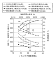
以下、図5のグラフを参照しながら熱交換塔の予測性能について説明する。
同グラフでは、熱交換塔2の高さ(以下、塔高さと呼ぶ)を10mにした場合と5mにした場合の予測性能をそれぞれ同じグラフにて対比させて示している。
同グラフにおいて、熱交換塔2に供給する錫とCOGの割合をメタル/ガス質量流量比で表し、塔下部2aに貯溜される錫の温度を液体金属浴温度として表し、錫の液滴が熱交換塔2内で占める割合を液敵空間占有率で表している。
同グラフにおいて、COGの出口温度は熱交換器の低温側温度、すなわち、散液される錫の温度250℃に向けて漸近する(L1、L2参照)。
塔下部2aに貯溜される錫の設計温度を、タールを揮発させるのに必要とされる温度500℃とすると、塔高さが5m(L3参照)の場合の熱交換効率は82%となる。一方、塔高さが10m(L4参照)の場合の熱交換効率は95~96%となる。仮に、塔高さ10mの場合と同等の熱交換効率を塔高さ5mで得ようとすると、メタル/ガス質量流量比を大幅に高めなければならず、そうすると、液体金属の循環量が過剰となり液体金属浴温度(L5参照)が500℃を下回ることになる。なお、L6は塔高さ10mの場合の液体金属浴温度を示している。
メタル/ガス質量流量比が増加すれば、錫の送液ポンプ(図1の第一竪型ポンプ6および第二竪型ポンプ8)動力と錫粒子に作用する抗力によってブロワ(図1のブロワ17)の動力が増加して塔高さ5mの回収熱/投入動力比、塔高さ10mの回収熱/投入動力比はともに減少する。
また、図5のグラフに示されるように、熱交換塔2内の空間における液体錫の空間占有率は、塔高さにほとんど依存せず、メタル/ガス質量流量比にほぼ対応しており、しかも0.1%未満の小さな値になっている。この計算結果から、以下のことが分かる。
(a)熱交換効率
メタル/ガス質量流量比の増加と共に接触面積が増加して熱交換効率は増加するが、効率95%程度までの増加率は大きい。錫を散液するようにした直接接触の効率が優れていることが分かる。
メタル/ガス質量流量比の増加と共に接触面積が増加して熱交換効率は増加するが、効率95%程度までの増加率は大きい。錫を散液するようにした直接接触の効率が優れていることが分かる。
(b)COG出口温度
COG出口温度は熱交換器の低温側の温度250℃に向けて漸近し、その傾向は熱交換効率と上下対称のようになる。もし熱媒にガリウムのようなさらなる低融点金属を用いれば、250℃以下まで十分に熱回収できることになる。
COG出口温度は熱交換器の低温側の温度250℃に向けて漸近し、その傾向は熱交換効率と上下対称のようになる。もし熱媒にガリウムのようなさらなる低融点金属を用いれば、250℃以下まで十分に熱回収できることになる。
(c)液体金属浴温度
液体金属浴の温度が450℃以下になると、熱交換塔2下部の液体金属浴において時間と共にタールが常に蓄積することになり、錫との比重分離に加えて別途、タールの排出手段が必要になり好ましくない。
液体金属浴の温度が450℃以下になると、熱交換塔2下部の液体金属浴において時間と共にタールが常に蓄積することになり、錫との比重分離に加えて別途、タールの排出手段が必要になり好ましくない。
また、液体金属浴の温度が低下すると、錫を熱媒にしたボイラなどの熱利用設備の規模が大きくなる。熱交換効率ηが大きくなると熱回収が増加することによりこの温度は上昇するはずであるが、実際にはメタル/ガス質量流量比がそれ以上に増加し、メタル/ガス質量流量比の増加に対して、液体金属浴の温度は低下する傾向を示す。
450℃程度と言われているタール凝縮開始に対し、余裕をみて500℃を液体金属浴の最低温度とすると、熱交換の高さが10mの場合ではメタル/ガス質量流量比は32(この時の熱交換効率は95%)が上限であり、一方、熱交換の高さが5mの場合ではメタル/ガス質量流量比27(この時の熱交換効率は82%)が上限になる。したがって、両者の熱交換効率を比較すると、熱交換高さ10mを採用する方が有利である。
(d)回収熱/投入動力比
一方、回収熱/投入動力比を見ると、メタル/ガス質量流量比の増加と共に錫の送液ポンプ動力と錫粒子に作用する抗力に起因するブロワ動力が増加して回収熱/投入動力比は減少する(L7、L8参照)。しかし、その比は200前後であり、図5のグラフに示す範囲では投入動力が設備設計を制限することにならない。
一方、回収熱/投入動力比を見ると、メタル/ガス質量流量比の増加と共に錫の送液ポンプ動力と錫粒子に作用する抗力に起因するブロワ動力が増加して回収熱/投入動力比は減少する(L7、L8参照)。しかし、その比は200前後であり、図5のグラフに示す範囲では投入動力が設備設計を制限することにならない。
以上のことから、顕熱回収装置を設計するには液体金属浴温度を睨みながら熱回収効率が最大になる点を選択することになる。したがって、熱交換塔2の有効高さを10mとし、メタル/ガス質量流量比を32にすることが好ましい。
ほぼその条件に等しい熱交換塔高さ10m、メタル/ガス質量流量比30.6での熱交換塔内部のCOGと各粒径の液体金属粒子の温度分布を図6のグラフに示す。
図6のグラフにおける縦軸は熱交換塔2の高さを示しており、0mは錫の液面レベルL(図1参照)に相当し、10mは塔頂部2bに相当している。横軸は温度を示している。各種粒子径の錫を10mの高さから250℃の温度で噴射する一方で熱交換塔2の下部から800℃のCOGが供給された場合を示している。
粒子径が小さい(粒子径0.5mm)ものほど比表面積が大きいため、熱交換によってすばやく温度上昇するが、粒子径が大きくなると(粒子径2.5mm)温度上昇が遅くなる。
熱交換塔2の高さ5mの位置には上述したように樋4が設けられているため、この樋4の高さでは、粒子径2.5mmの錫は250℃から290℃に温度上昇し、粒子径0.5mmの錫は400℃まで温度上昇し、平均温度は約350℃となる。
したがって、高さ5mの位置に樋4を設ければ、沸点が最低290℃までのタール成分、例えば、ベンゾ[a]ピレンやフェナントレン等を回収することができる。よって、熱交換塔2の丁度、中間高さの5m位置に開口率50%格子状の樋4を設置すればよいことになる。
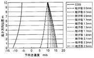
次に、同一条件でのCOGと各粒径の液体金属粒子の速度分布を図7に示す。
図7のグラフにおいて、縦軸は熱交換塔2の高さ方向位置を示し、横軸は下向き速度を示している。
COGは熱交換塔2内に導入された時点で-12m/sの速度(COGの流れは上向きであるため-の値で示している)を持っているが、熱交換塔2内を上昇するにつれて冷却され、冷却による密度の増加によって減速する。
また、錫については、粒子径の小さい錫、例えば粒子径0.5mmのものは散液ミストノズル3から初速10m/sで噴射されるが、熱交換塔2内を上昇するCOGの流体抗力によって5m/s程度まで減速されながら落下する。一方、粒子径2.5mmのものは流体抗力よりも重力が上回り、加速しながら落下する。
なお、図7のグラフには図示していないが、粒子径0.4mm以下の粒子は下向き速度が最終的にマイナスになる。すなわち、上昇して液体金属バスに落下しない。
以上のことから、粒子径0.4mm以下(2.9wt%)の錫粒子がCOGとともに上昇して排出されることを許容した設計が成立していることが分かる。
[2]並流式コークス炉ガス顕熱回収装置
図8に示す並流式コークス炉ガス顕熱回収装置(以下、並流式顕熱回収装置と略称する)20は、図1に示した熱交換塔2と熱媒回収槽5とを一体化した構成となっている。なお、図8において、図1と同じ構成要素については同一符号を付してその説明を省略する。
図8に示す並流式コークス炉ガス顕熱回収装置(以下、並流式顕熱回収装置と略称する)20は、図1に示した熱交換塔2と熱媒回収槽5とを一体化した構成となっている。なお、図8において、図1と同じ構成要素については同一符号を付してその説明を省略する。
800℃のCOGは、COG供給ライン21を介し熱交換塔22の塔頂部22aから熱交換塔22内に導入され、熱交換塔2の塔下部22bから接続管18を介して引き出されるようになっている。上記COG供給ライン21および接続管18は、COGを熱交換塔22の塔頂部22aから供給し、熱交換塔22の塔下部22bから引き出す第二のガス給排路として機能する。
それにより、熱交換塔22の内部を降下する過程で散液ミストノズル3から散液される錫との間で並流式の直接接触熱交換が行われる。
熱交換塔22内を落下するタール付着錫液滴は、熱交換塔22の下部に設けられた比重分離槽としての熱媒回収槽23で受け止められ、一方、COGは320℃程度まで冷却されて塔下部22bから安水散水装置11へ送り出されるようになっている。
上記熱交換塔22の径はφ3.6m、高さHは20mである。
上記熱交換塔22の径はφ3.6m、高さHは20mである。
図1に示した向流式顕熱回収装置における直接接触熱交換では、上向きに流れるCOGの抗力によって液滴がゆっくりと落下し液滴との接触時間を長くすることができるが、並流式の直接接触熱交換では向流式の直接接触熱交換に比べ、熱交換効率が低下する。そこで、並流式顕熱回収装置20では、熱交換塔22の高さを高くして熱交換効率の低下を補っている。
上記構成を有する並流式顕熱回収装置20では、タールが凝縮した熱媒(錫液滴)の一部を熱交換塔22の外部に取り出すための通路部を設けず、熱媒のすべてを熱交換塔22の下部に設けられた熱媒回収槽23に流し込むようにしている。それにより、樋4、第一竪型ポンプ6、第二散液ノズル7を省略することができ、装置の簡略化を図ることができる。なお、図中、符号24は均圧管である。
図9は、並流式顕熱回収装置による熱交換塔の性能予測計算結果を示したグラフである。
同グラフにおいて、横軸は熱交換塔22に供給する錫とコークス炉ガスの割合を示したメタル/ガス質量流量比であり、左側縦軸は回収熱/投入動力比および液体金属浴温度℃(熱媒回収槽23に貯溜される錫の温度)を示し、右側縦軸は熱交換効率%を示している。
同グラフにおいて、横軸は熱交換塔22に供給する錫とコークス炉ガスの割合を示したメタル/ガス質量流量比であり、左側縦軸は回収熱/投入動力比および液体金属浴温度℃(熱媒回収槽23に貯溜される錫の温度)を示し、右側縦軸は熱交換効率%を示している。
並流式顕熱回収装置20では、90%の熱交換効率を目指す場合、並流式接触であるためにCOG質量流量に対して125倍の熱媒質量流量が必要となる。そのため、並流式顕熱回収装置20に投入したポンプとブロワの動力に対して24倍の熱回収しかできないことになる。
上述した向流式顕熱回収装置1では、COG質量流量に対して30.6倍の熱媒質量流量を必要とするだけで、投入したポンプとブロワの動力に対して184倍の熱回収ができていた(図5のグラフにおけるL8参照)ことと比較すると、並流式顕熱回収装置20では向流式顕熱回収装置1に比べ約8倍の動力が必要になる。
すなわち、動力に関してはポンプ動力の方がブロワ動力よりも圧倒的に大きく、ポンプ動力P(W)はmドット×Hに比例し、下記式

並流式の場合のポンプ動力:mドット×H(125×20)×g/ηを、向流式の場合のポンプ動力:mドット×H(30.6×10)×g/ηで除算すると8.17が得られ、約8倍の動力となる。
しかしながら、並流式顕熱回収装置20によれば、設備と運転方法を極めて簡略化することができるという利点がある。
例えば、向流式顕熱回収装置1では、熱媒回収槽5の液面レベルを一定に維持するよう、第二散液ミストノズル7用の第一竪型ポンプ6の運転を制御することが求められるが、並流式顕熱回収装置20によれば、そのような液面レベルの制御が必要とされない。しかも、熱媒の一部を熱交換塔22の外部に取り出すための樋4も必要としないため、通路部4bが閉塞するおそれもなくメンテナンスが容易になる。
従来、COGは約800℃の顕熱を持っていることから0.95MJ/Nm3-COG程度の発生熱量があるにもかかわらず、450℃以下まで冷却するとタールが凝縮して伝熱管に付着することから、これまでほとんど熱回収が行われていなかった。
しかしながら、上述した向流式および並流式顕熱回収装置によれば、高温のCOGに錫液滴を直接接触させることで液体錫の表面にタールを凝縮させ、その後、タールと液体錫を比重分離させるように構成したため、本発明をコークス炉に適用すれば、大幅なコストダウンが実現でき、CO2の排出量も大幅に削減することができる。
なお、上述した向流式顕熱回収装置では、熱交換塔2内に樋4を設け、タールの付着した錫液滴を受け止めて熱媒回収槽5へ供給するように構成したが、COG顕熱を回収するにあたり、熱媒質量流量を増加させて液体金属浴の温度を350℃程度まで下げる運転を行えば、樋4を設けず熱交換塔2の下部に熱媒回収槽を設けることもできる。
本願は、2011年5月20日に出願された日本国特許出願第2011-114027号に基づく優先権の利益を主張するものである。2011年5月20日に出願された日本国特許出願第2011-114027号の明細書の全内容が、本願に参考のため援用される。
本発明のコークス炉ガス顕熱回収装置は、コークス炉で発生するCOGの顕熱を回収して省エネルギーを図る分野に利用することができる。
1 向流式顕熱回収装置
2 熱交換塔(熱交換装置)
2a 塔下部
2b 塔頂部
3 散液ミストノズル(散液ノズル)
4 樋
4a 液滴受け部
4b 通路部
4c 開口部
4d 潜り堰
5 熱媒回収槽
5a 排出口
5b 棚部
6 第一竪型ポンプ
7 第二散液ミストノズル(第二散液ノズル)
8 第二竪型ポンプ
9 ボイラ
10 タールデカンター
11 安水散水装置
12 ポンプ
13 循環路
14 コンベヤ
15 第二コンベヤ
16 第3室
17 ブロワ
18 接続管
19 排出管
20 並流式顕熱回収装置
21 COG供給ライン
22 熱交換塔
23 熱媒回収槽
2 熱交換塔(熱交換装置)
2a 塔下部
2b 塔頂部
3 散液ミストノズル(散液ノズル)
4 樋
4a 液滴受け部
4b 通路部
4c 開口部
4d 潜り堰
5 熱媒回収槽
5a 排出口
5b 棚部
6 第一竪型ポンプ
7 第二散液ミストノズル(第二散液ノズル)
8 第二竪型ポンプ
9 ボイラ
10 タールデカンター
11 安水散水装置
12 ポンプ
13 循環路
14 コンベヤ
15 第二コンベヤ
16 第3室
17 ブロワ
18 接続管
19 排出管
20 並流式顕熱回収装置
21 COG供給ライン
22 熱交換塔
23 熱媒回収槽
Claims (12)
- コークス炉で発生するコークス炉ガスと熱媒とを直接接触させ、その熱媒の表面にタールを凝縮させる熱交換塔と、
タールが付着した上記熱媒を集合させ、比重分離によって上記熱媒からタールを分離させ、上記熱媒を回収する熱媒回収槽とを備えていることを特徴とするコークス炉ガス顕熱回収装置。 - 上記熱媒として上記タールよりも比重が重い熱媒を使用する請求項1に記載のコークス炉ガス顕熱回収装置。
- 上記熱交換塔内の熱交換によって冷却されたコークス炉ガスを導いて安水を散水し、未凝縮のタール分を凝縮させ貯溜する安水散水装置を有する請求項1または2に記載のコークス炉ガス顕熱回収装置。
- 上記安水散水装置からの安水と凝縮液とを導いて比重分離させるタールデカンターを有する請求項3に記載のコークス炉ガス顕熱回収装置。
- 上記タールデカンターの最下層に沈殿した熱媒とタール滓との混合物を、上記熱媒回収槽に供給する掻出装置を有する請求項4に記載のコークス炉ガス顕熱回収装置。
- 上記熱媒を上記熱交換塔の上部から散液する散液ノズルを有する請求項1に記載のコークス炉ガス顕熱回収装置。
- 上記コークス炉ガスを上記熱交換塔の塔下部から供給し、上記熱交換塔の塔頂部から引き出すガス給排路を有する請求項1に記載のコークス炉ガス顕熱回収装置。
- タールが付着した上記熱媒の一部を上記熱交換塔の外部に取り出す通路部を有し、この通路部の出口部に上記熱媒回収槽が備えられている請求項7に記載のコークス炉ガス顕熱回収装置。
- 熱交換に供せられタールが付着した上記熱媒を受ける液滴受け部を上記熱交換塔内に有し、この液滴受け部が上記通路部の入口部と接続されている請求項8に記載のコークス炉ガス顕熱回収装置。
- 上記熱媒回収槽において分離された上記熱媒を、上記液滴受け部の下方から散液する第二散液ノズルが設けられている請求項9に記載のコークス炉ガス顕熱回収装置。
- 上記コークス炉ガスを上記熱交換塔の塔頂部から供給し、上記熱交換塔の塔下部から引き出す第二のガス給排路を有する請求項1に記載のコークス炉ガス顕熱回収装置。
- 上記熱交換塔の下部に上記熱媒回収槽が設けられている請求項11に記載のコークス炉ガス顕熱回収装置。
Priority Applications (2)
| Application Number | Priority Date | Filing Date | Title |
|---|---|---|---|
| CN201280014682.0A CN103459556B (zh) | 2011-05-20 | 2012-04-27 | 炼焦炉气体显热回收装置 |
| KR1020137030374A KR101552416B1 (ko) | 2011-05-20 | 2012-04-27 | 코크스로 가스 현열 회수 장치 |
Applications Claiming Priority (2)
| Application Number | Priority Date | Filing Date | Title |
|---|---|---|---|
| JP2011-114027 | 2011-05-20 | ||
| JP2011114027 | 2011-05-20 |
Publications (1)
| Publication Number | Publication Date |
|---|---|
| WO2012160944A1 true WO2012160944A1 (ja) | 2012-11-29 |
Family
ID=47217027
Family Applications (1)
| Application Number | Title | Priority Date | Filing Date |
|---|---|---|---|
| PCT/JP2012/061315 Ceased WO2012160944A1 (ja) | 2011-05-20 | 2012-04-27 | コークス炉ガス顕熱回収装置 |
Country Status (4)
| Country | Link |
|---|---|
| JP (1) | JP5820328B2 (ja) |
| KR (1) | KR101552416B1 (ja) |
| CN (1) | CN103459556B (ja) |
| WO (1) | WO2012160944A1 (ja) |
Cited By (1)
| Publication number | Priority date | Publication date | Assignee | Title |
|---|---|---|---|---|
| CN114534313A (zh) * | 2022-03-03 | 2022-05-27 | 广东韶钢松山股份有限公司 | 一种焦油氨水分离槽顶部浮油消除方法 |
Citations (4)
| Publication number | Priority date | Publication date | Assignee | Title |
|---|---|---|---|---|
| JPS5311901A (en) * | 1976-07-16 | 1978-02-02 | Otto & Co Gmbh Dr C | Method and apparatus for cooling gas containing solids* tar and naphthalene |
| JPS57117591A (en) * | 1981-01-12 | 1982-07-22 | Sumitomo Metal Ind Ltd | Heat recovery from coke oven by-product gas |
| JPS6060182A (ja) * | 1983-09-13 | 1985-04-06 | Sumikin Coke Co Ltd | コ−クス炉ガス液の顕熱回収法 |
| JP2000093728A (ja) * | 1998-09-22 | 2000-04-04 | Ishikawajima Harima Heavy Ind Co Ltd | ガス精製方法及びその装置 |
Family Cites Families (1)
| Publication number | Priority date | Publication date | Assignee | Title |
|---|---|---|---|---|
| DE1751090A1 (de) * | 1968-04-02 | 1971-10-07 | Basf Ag | Verfahren zur Kuehlung von Spalt- oder Synthesegas und Waermeaustauscher zur Durchfuehrung des Verfahrens |
-
2012
- 2012-04-17 JP JP2012093669A patent/JP5820328B2/ja not_active Expired - Fee Related
- 2012-04-27 CN CN201280014682.0A patent/CN103459556B/zh not_active Expired - Fee Related
- 2012-04-27 KR KR1020137030374A patent/KR101552416B1/ko not_active Expired - Fee Related
- 2012-04-27 WO PCT/JP2012/061315 patent/WO2012160944A1/ja not_active Ceased
Patent Citations (4)
| Publication number | Priority date | Publication date | Assignee | Title |
|---|---|---|---|---|
| JPS5311901A (en) * | 1976-07-16 | 1978-02-02 | Otto & Co Gmbh Dr C | Method and apparatus for cooling gas containing solids* tar and naphthalene |
| JPS57117591A (en) * | 1981-01-12 | 1982-07-22 | Sumitomo Metal Ind Ltd | Heat recovery from coke oven by-product gas |
| JPS6060182A (ja) * | 1983-09-13 | 1985-04-06 | Sumikin Coke Co Ltd | コ−クス炉ガス液の顕熱回収法 |
| JP2000093728A (ja) * | 1998-09-22 | 2000-04-04 | Ishikawajima Harima Heavy Ind Co Ltd | ガス精製方法及びその装置 |
Cited By (1)
| Publication number | Priority date | Publication date | Assignee | Title |
|---|---|---|---|---|
| CN114534313A (zh) * | 2022-03-03 | 2022-05-27 | 广东韶钢松山股份有限公司 | 一种焦油氨水分离槽顶部浮油消除方法 |
Also Published As
| Publication number | Publication date |
|---|---|
| CN103459556B (zh) | 2015-02-04 |
| JP5820328B2 (ja) | 2015-11-24 |
| KR101552416B1 (ko) | 2015-09-10 |
| CN103459556A (zh) | 2013-12-18 |
| JP2013007027A (ja) | 2013-01-10 |
| KR20140000350A (ko) | 2014-01-02 |
Similar Documents
| Publication | Publication Date | Title |
|---|---|---|
| US7156381B2 (en) | Heat recovery using fluidized spray tower | |
| AU743817B2 (en) | Temperature control device and temperature control method for high-temperature exhaust gas | |
| EP1877522B1 (en) | Method for quenching synthesis gas | |
| CN103826737B (zh) | 多级循环流化床合成气冷却 | |
| JP2013543523A (ja) | スラグを含む高温ガス流を処理するための装置と方法 | |
| US4702818A (en) | Process for recovering heat of a tar-containing high-temperature gas | |
| JP5820328B2 (ja) | コークス炉ガス顕熱回収装置 | |
| EP2502883A1 (en) | Black water treatment systems and methods | |
| CN204981786U (zh) | 一种煤气除尘降温系统及煤气化系统 | |
| CN113462423B (zh) | 处理气相夹带的方法和放空系统 | |
| CN221638466U (zh) | 一种初冷器上段冷凝液固液分离喷洒装置 | |
| CN201259384Y (zh) | 一种间接直接循环喷洒冷却气体捕集器 | |
| US20120131852A1 (en) | Moisture removal for gasification quench chamber assembly | |
| CN113265274B (zh) | 一种节能防堵的煤气洗涤方法 | |
| CN111712676A (zh) | 具有加压传热流体系统的太阳能接收器设备 | |
| CN105289179A (zh) | 一种低阻强制水冷滴型管式除雾器及除雾方法 | |
| CN204311033U (zh) | 多级的原始气体洗涤系统 | |
| CN106839808B (zh) | 荒煤气余热高低温综合回收系统及方法 | |
| CN114622056B (zh) | 转炉烟气激冷器、降温装置及提高降温效率的方法 | |
| CN107537266A (zh) | 一种高温热解气体的除尘系统及除尘方法 | |
| CN201043166Y (zh) | 穹顶式除尘熄焦塔 | |
| CN207532991U (zh) | 一种高温热解气体的除尘系统 | |
| CN203768319U (zh) | 一种煤气余热回收利用装置 | |
| CN105419842B (zh) | 废塑料熔盐二次加热裂解塔 | |
| JP2021166991A (ja) | サイクロン式凝縮および冷却システム |
Legal Events
| Date | Code | Title | Description |
|---|---|---|---|
| 121 | Ep: the epo has been informed by wipo that ep was designated in this application |
Ref document number: 12789838 Country of ref document: EP Kind code of ref document: A1 |
|
| ENP | Entry into the national phase |
Ref document number: 20137030374 Country of ref document: KR Kind code of ref document: A |
|
| NENP | Non-entry into the national phase |
Ref country code: DE |
|
| 122 | Ep: pct application non-entry in european phase |
Ref document number: 12789838 Country of ref document: EP Kind code of ref document: A1 |