WO2012160681A1 - 電池 - Google Patents
電池 Download PDFInfo
- Publication number
- WO2012160681A1 WO2012160681A1 PCT/JP2011/062021 JP2011062021W WO2012160681A1 WO 2012160681 A1 WO2012160681 A1 WO 2012160681A1 JP 2011062021 W JP2011062021 W JP 2011062021W WO 2012160681 A1 WO2012160681 A1 WO 2012160681A1
- Authority
- WO
- WIPO (PCT)
- Prior art keywords
- battery
- external
- case
- energization
- terminal
- Prior art date
- Legal status (The legal status is an assumption and is not a legal conclusion. Google has not performed a legal analysis and makes no representation as to the accuracy of the status listed.)
- Ceased
Links
Images













Classifications
-
- H—ELECTRICITY
- H01—ELECTRIC ELEMENTS
- H01M—PROCESSES OR MEANS, e.g. BATTERIES, FOR THE DIRECT CONVERSION OF CHEMICAL ENERGY INTO ELECTRICAL ENERGY
- H01M10/00—Secondary cells; Manufacture thereof
- H01M10/05—Accumulators with non-aqueous electrolyte
- H01M10/052—Li-accumulators
- H01M10/0525—Rocking-chair batteries, i.e. batteries with lithium insertion or intercalation in both electrodes; Lithium-ion batteries
-
- H—ELECTRICITY
- H01—ELECTRIC ELEMENTS
- H01M—PROCESSES OR MEANS, e.g. BATTERIES, FOR THE DIRECT CONVERSION OF CHEMICAL ENERGY INTO ELECTRICAL ENERGY
- H01M10/00—Secondary cells; Manufacture thereof
- H01M10/05—Accumulators with non-aqueous electrolyte
- H01M10/058—Construction or manufacture
- H01M10/0587—Construction or manufacture of accumulators having only wound construction elements, i.e. wound positive electrodes, wound negative electrodes and wound separators
-
- H—ELECTRICITY
- H01—ELECTRIC ELEMENTS
- H01M—PROCESSES OR MEANS, e.g. BATTERIES, FOR THE DIRECT CONVERSION OF CHEMICAL ENERGY INTO ELECTRICAL ENERGY
- H01M50/00—Constructional details or processes of manufacture of the non-active parts of electrochemical cells other than fuel cells, e.g. hybrid cells
- H01M50/50—Current conducting connections for cells or batteries
- H01M50/571—Methods or arrangements for affording protection against corrosion; Selection of materials therefor
-
- B—PERFORMING OPERATIONS; TRANSPORTING
- B60—VEHICLES IN GENERAL
- B60L—PROPULSION OF ELECTRICALLY-PROPELLED VEHICLES; SUPPLYING ELECTRIC POWER FOR AUXILIARY EQUIPMENT OF ELECTRICALLY-PROPELLED VEHICLES; ELECTRODYNAMIC BRAKE SYSTEMS FOR VEHICLES IN GENERAL; MAGNETIC SUSPENSION OR LEVITATION FOR VEHICLES; MONITORING OPERATING VARIABLES OF ELECTRICALLY-PROPELLED VEHICLES; ELECTRIC SAFETY DEVICES FOR ELECTRICALLY-PROPELLED VEHICLES
- B60L50/00—Electric propulsion with power supplied within the vehicle
- B60L50/50—Electric propulsion with power supplied within the vehicle using propulsion power supplied by batteries or fuel cells
- B60L50/60—Electric propulsion with power supplied within the vehicle using propulsion power supplied by batteries or fuel cells using power supplied by batteries
- B60L50/64—Constructional details of batteries specially adapted for electric vehicles
-
- H—ELECTRICITY
- H01—ELECTRIC ELEMENTS
- H01M—PROCESSES OR MEANS, e.g. BATTERIES, FOR THE DIRECT CONVERSION OF CHEMICAL ENERGY INTO ELECTRICAL ENERGY
- H01M2220/00—Batteries for particular applications
- H01M2220/20—Batteries in motive systems, e.g. vehicle, ship, plane
-
- H—ELECTRICITY
- H01—ELECTRIC ELEMENTS
- H01M—PROCESSES OR MEANS, e.g. BATTERIES, FOR THE DIRECT CONVERSION OF CHEMICAL ENERGY INTO ELECTRICAL ENERGY
- H01M50/00—Constructional details or processes of manufacture of the non-active parts of electrochemical cells other than fuel cells, e.g. hybrid cells
- H01M50/10—Primary casings; Jackets or wrappings
- H01M50/172—Arrangements of electric connectors penetrating the casing
- H01M50/174—Arrangements of electric connectors penetrating the casing adapted for the shape of the cells
- H01M50/176—Arrangements of electric connectors penetrating the casing adapted for the shape of the cells for prismatic or rectangular cells
-
- H—ELECTRICITY
- H01—ELECTRIC ELEMENTS
- H01M—PROCESSES OR MEANS, e.g. BATTERIES, FOR THE DIRECT CONVERSION OF CHEMICAL ENERGY INTO ELECTRICAL ENERGY
- H01M50/00—Constructional details or processes of manufacture of the non-active parts of electrochemical cells other than fuel cells, e.g. hybrid cells
- H01M50/20—Mountings; Secondary casings or frames; Racks, modules or packs; Suspension devices; Shock absorbers; Transport or carrying devices; Holders
- H01M50/204—Racks, modules or packs for multiple batteries or multiple cells
- H01M50/207—Racks, modules or packs for multiple batteries or multiple cells characterised by their shape
- H01M50/209—Racks, modules or packs for multiple batteries or multiple cells characterised by their shape adapted for prismatic or rectangular cells
-
- H—ELECTRICITY
- H01—ELECTRIC ELEMENTS
- H01M—PROCESSES OR MEANS, e.g. BATTERIES, FOR THE DIRECT CONVERSION OF CHEMICAL ENERGY INTO ELECTRICAL ENERGY
- H01M50/00—Constructional details or processes of manufacture of the non-active parts of electrochemical cells other than fuel cells, e.g. hybrid cells
- H01M50/20—Mountings; Secondary casings or frames; Racks, modules or packs; Suspension devices; Shock absorbers; Transport or carrying devices; Holders
- H01M50/247—Mountings; Secondary casings or frames; Racks, modules or packs; Suspension devices; Shock absorbers; Transport or carrying devices; Holders specially adapted for portable devices, e.g. mobile phones, computers, hand tools or pacemakers
-
- H—ELECTRICITY
- H01—ELECTRIC ELEMENTS
- H01M—PROCESSES OR MEANS, e.g. BATTERIES, FOR THE DIRECT CONVERSION OF CHEMICAL ENERGY INTO ELECTRICAL ENERGY
- H01M50/00—Constructional details or processes of manufacture of the non-active parts of electrochemical cells other than fuel cells, e.g. hybrid cells
- H01M50/20—Mountings; Secondary casings or frames; Racks, modules or packs; Suspension devices; Shock absorbers; Transport or carrying devices; Holders
- H01M50/249—Mountings; Secondary casings or frames; Racks, modules or packs; Suspension devices; Shock absorbers; Transport or carrying devices; Holders specially adapted for aircraft or vehicles, e.g. cars or trains
-
- H—ELECTRICITY
- H01—ELECTRIC ELEMENTS
- H01M—PROCESSES OR MEANS, e.g. BATTERIES, FOR THE DIRECT CONVERSION OF CHEMICAL ENERGY INTO ELECTRICAL ENERGY
- H01M50/00—Constructional details or processes of manufacture of the non-active parts of electrochemical cells other than fuel cells, e.g. hybrid cells
- H01M50/50—Current conducting connections for cells or batteries
- H01M50/543—Terminals
- H01M50/547—Terminals characterised by the disposition of the terminals on the cells
- H01M50/55—Terminals characterised by the disposition of the terminals on the cells on the same side of the cell
-
- H—ELECTRICITY
- H01—ELECTRIC ELEMENTS
- H01M—PROCESSES OR MEANS, e.g. BATTERIES, FOR THE DIRECT CONVERSION OF CHEMICAL ENERGY INTO ELECTRICAL ENERGY
- H01M50/00—Constructional details or processes of manufacture of the non-active parts of electrochemical cells other than fuel cells, e.g. hybrid cells
- H01M50/50—Current conducting connections for cells or batteries
- H01M50/543—Terminals
- H01M50/552—Terminals characterised by their shape
- H01M50/553—Terminals adapted for prismatic, pouch or rectangular cells
-
- H—ELECTRICITY
- H01—ELECTRIC ELEMENTS
- H01M—PROCESSES OR MEANS, e.g. BATTERIES, FOR THE DIRECT CONVERSION OF CHEMICAL ENERGY INTO ELECTRICAL ENERGY
- H01M50/00—Constructional details or processes of manufacture of the non-active parts of electrochemical cells other than fuel cells, e.g. hybrid cells
- H01M50/50—Current conducting connections for cells or batteries
- H01M50/543—Terminals
- H01M50/562—Terminals characterised by the material
-
- H—ELECTRICITY
- H01—ELECTRIC ELEMENTS
- H01M—PROCESSES OR MEANS, e.g. BATTERIES, FOR THE DIRECT CONVERSION OF CHEMICAL ENERGY INTO ELECTRICAL ENERGY
- H01M50/00—Constructional details or processes of manufacture of the non-active parts of electrochemical cells other than fuel cells, e.g. hybrid cells
- H01M50/50—Current conducting connections for cells or batteries
- H01M50/543—Terminals
- H01M50/564—Terminals characterised by their manufacturing process
- H01M50/566—Terminals characterised by their manufacturing process by welding, soldering or brazing
-
- Y—GENERAL TAGGING OF NEW TECHNOLOGICAL DEVELOPMENTS; GENERAL TAGGING OF CROSS-SECTIONAL TECHNOLOGIES SPANNING OVER SEVERAL SECTIONS OF THE IPC; TECHNICAL SUBJECTS COVERED BY FORMER USPC CROSS-REFERENCE ART COLLECTIONS [XRACs] AND DIGESTS
- Y02—TECHNOLOGIES OR APPLICATIONS FOR MITIGATION OR ADAPTATION AGAINST CLIMATE CHANGE
- Y02E—REDUCTION OF GREENHOUSE GAS [GHG] EMISSIONS, RELATED TO ENERGY GENERATION, TRANSMISSION OR DISTRIBUTION
- Y02E60/00—Enabling technologies; Technologies with a potential or indirect contribution to GHG emissions mitigation
- Y02E60/10—Energy storage using batteries
-
- Y—GENERAL TAGGING OF NEW TECHNOLOGICAL DEVELOPMENTS; GENERAL TAGGING OF CROSS-SECTIONAL TECHNOLOGIES SPANNING OVER SEVERAL SECTIONS OF THE IPC; TECHNICAL SUBJECTS COVERED BY FORMER USPC CROSS-REFERENCE ART COLLECTIONS [XRACs] AND DIGESTS
- Y02—TECHNOLOGIES OR APPLICATIONS FOR MITIGATION OR ADAPTATION AGAINST CLIMATE CHANGE
- Y02T—CLIMATE CHANGE MITIGATION TECHNOLOGIES RELATED TO TRANSPORTATION
- Y02T10/00—Road transport of goods or passengers
- Y02T10/60—Other road transportation technologies with climate change mitigation effect
- Y02T10/70—Energy storage systems for electromobility, e.g. batteries
Definitions
- the present invention relates to a battery case, an electrode body accommodated in the battery case, an energization terminal member that extends through the battery case and extends to the outside of the battery case while being connected to the electrode body inside the battery case,
- the present invention relates to a battery including an insulating resin member that is molded integrally with a terminal member and a battery case, and that seals the current-carrying terminal member and the battery case while insulating them.
- a battery is known in which an insulating resin member separately molded is interposed between a current-carrying terminal member and a battery case and sealed while insulating them. Further, a battery is known in which the energizing terminal member is formed of one metal member and the insulating resin member is integrally formed by injection molding using a case lid member of the battery case and the energizing terminal member.
- Patent Document 1 discloses such a battery (refer to the claims of Patent Document 1 and FIGS. 1 and 2). Such a battery has an advantage that the number of parts is small and the number of steps can be reduced.
- the current-carrying terminal member in order to increase the sealing performance between the current-carrying terminal member and the insulating resin member integrated with the current-carrying terminal member, if the area of the current-carrying terminal member that contacts the insulating resin member is increased, the current-carrying terminal member has a complicated shape. It tends to be. In addition, it is easy to connect an external battery connection terminal (such as a crimping terminal attached to the end of a bus bar or cable) to the current supply terminal member, or a contact resistance between the current supply terminal member and the external battery connection terminal. If it can be lowered, the energizing terminal member tends to have a complicated shape.
- an external battery connection terminal such as a crimping terminal attached to the end of a bus bar or cable
- the current-carrying terminal member has a complicated shape, it may be difficult to make the current-carrying terminal member itself when the current-carrying terminal member is formed from a single metal member as described above. Further, prior to injection molding of the insulating resin member, when the energizing terminal member is inserted into the terminal insertion hole provided in the case lid member, the insertability may be deteriorated, and the productivity may be deteriorated. For this reason, in a conventional battery in which an insulating resin member is injection-molded using a single conductive terminal member, the sealing property between the conductive terminal member and the insulating resin member is improved, and the conductive terminal member is connected to the battery connection terminal. It was difficult to achieve a form suitable for connection with the device.
- the present invention has been made in view of the current situation, and can improve the sealing performance between the current-carrying terminal member and the insulating resin member and make the current-carrying terminal member suitable for connection to the connection terminal outside the battery. It is an object to provide a battery that can be used.
- One aspect of the present invention for solving the above problems is a battery case formed by joining a first case member and a second case member, an electrode body accommodated in the battery case, and an interior of the battery case.
- the electrode body is connected to the electrode body while extending through the first case member to the outside of the battery case, and connected to an external battery connection terminal which is a connection terminal outside the battery.
- An energizing terminal member that constitutes a conduction path between the connection terminals outside the battery and a resin, and seals the energizing terminal member and the first case member while insulating and energizing the energizing terminal member.
- the inside / outside energization member to be taken out and the inside / outside energization member are separate members, and are arranged outside the battery case, and a base connected to the inside / outside energization member and the outside where the outside connection terminal is fastened
- An external energizing member including a connecting portion, and the insulating resin member is a battery formed integrally with the first case member and the inner and outer energizing members.
- the sealing property between the energizing terminal member (the inside / outside energizing member) and the insulating resin member can be enhanced, and the energizing terminal is separated from the shape of the inside / outside energizing member and the sealing property between the inside / outside conducting member and the insulating resin member.
- a member (its external energization member) can be made into a form suitable for connection with an external battery connection terminal.
- the inner and outer current-carrying members are subjected to a chemical surface treatment for improving adhesion to the resin on the surface, and the insulating resin member is subjected to the surface treatment.
- the battery is formed integrally with the internal / external energization member, and the external energization member is a battery in which a plating layer is formed at least on a contact surface of the external connection portion with which the external connection terminal contacts.
- the internal / external energization member is formed on the surface by the surface treatment and chemically bonds with the metal forming the internal / external energization member, and also chemically with the resin forming the insulating resin member.
- a battery having a film to be bonded is preferable.
- the film may be a battery containing 1,3,5-triazine.
- the inner and outer current-carrying member and the base of the external current-carrying member are preferably connected to each other by welding.
- the bolt is inserted into the screw insertion hole, and has a male screw portion having a male screw formed on the outer periphery thereof, and a head that is larger in diameter than the male screw portion and engages with the external connection portion.
- the insulating resin member is preferably a battery in which the head portion of the bolt is held non-rotatable about its axis.
- the external energization member is formed by bending a metal plate in the thickness direction, and the base, the external connection portion, and an upright portion that connects between them are cranks.
- the first case is configured such that the base extends along a through surface through which the inner and outer current-carrying member penetrates among the first case members, and an upright portion is bent from an end of the base.
- the battery is formed such that it rises in a direction away from the member, and the external connection portion is bent from the end portion of the rising portion and extends in parallel with the base portion.
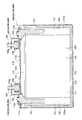
- FIG. 1 is a longitudinal sectional view showing a lithium ion secondary battery according to Embodiment 1.
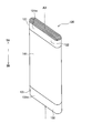
- FIG. 1 is a perspective view showing an electrode body according to Embodiment 1.
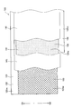
- FIG. 3 is a partial plan view illustrating a state in which the positive electrode plate and the negative electrode plate are overlapped with each other via a separator according to the first embodiment.
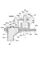
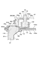
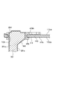
- FIG. 4 is a partial vertical cross-sectional view illustrating a case lid member, an energizing terminal member, a bolt, and an insulating resin member according to the first embodiment.
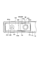
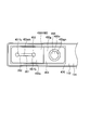
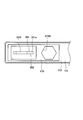
- FIG. 5 is a plan view of the case lid member, the energizing terminal member, the bolt, and the insulating resin member as viewed from above in FIG. 4 according to the first embodiment.
- FIG. 1 is a longitudinal sectional view showing a lithium ion secondary battery according to Embodiment 1.
- FIG. 1 is a perspective view showing an electrode body according to Embodiment 1.
- FIG. 3 is a partial plan view illustrating a
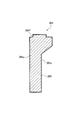
- FIG. 3 is a longitudinal sectional view illustrating an external energization member according to the first embodiment.
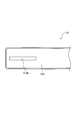
- FIG. 7 is a plan view of the external energization member as viewed from above in FIG. 6 according to the first embodiment. It is a longitudinal cross-sectional view which concerns on Embodiment 1 and shows an inside-and-outside electricity supply member.
- FIG. 9 is a plan view of the inner and outer current-carrying members as viewed from above in FIG. 8 according to the first embodiment.
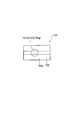
- FIG. 5 is a partial plan view of the case lid member as viewed from above in the vicinity of a terminal insertion hole according to the first embodiment.
- FIG. 5 is a longitudinal sectional view showing a state in which a resin is injected to integrally form an insulating resin member and a case lid member and an inner and outer current-carrying member are integrated with respect to the method for manufacturing a lithium ion secondary battery according to the first embodiment.
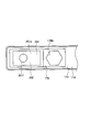
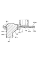
- FIG. 12 is a plan view of the method for manufacturing the lithium ion secondary battery according to Embodiment 1 when the case lid member, the energizing terminal member, and the insulating resin member are viewed from above in FIG. 11. It is a partial longitudinal cross-sectional view which concerns on Embodiment 2 and shows a case cover member, an electricity supply terminal member, a volt
- FIG. 14 is a plan view of the case lid member, the energizing terminal member, the bolt, and the insulating resin member as viewed from above in FIG. 13 according to the second embodiment. It is a longitudinal cross-sectional view which concerns on Embodiment 2 and shows an inside-and-outside electricity supply member.
- FIG. 5 is a longitudinal sectional view showing a state in which a resin is injected and an insulating resin member is integrally formed and a case lid member and an internal / external energization member are integrated with respect to the method for manufacturing a lithium ion secondary battery according to Embodiment 2.
- FIG. 5 is a longitudinal sectional view showing a state in which a resin is injected and an insulating resin member is integrally formed and a case lid member and an internal / external energization member are integrated with respect to the method for manufacturing a lithium ion secondary battery according to Embodiment 2.
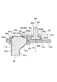
- FIG. 17 is a plan view of the method for manufacturing a lithium ion secondary battery according to Embodiment 2 when the case lid member, the energizing terminal member, and the insulating resin member are viewed from above in FIG. 16. It is a partial longitudinal cross-sectional view which concerns on Embodiment 3 and shows a case cover member, an electricity supply terminal member, a volt
- FIG. 19 is a plan view of the case lid member, the energizing terminal member, the bolt, and the insulating resin member as viewed from above in FIG. 18 according to the third embodiment. It is a longitudinal cross-sectional view which concerns on Embodiment 3 and shows an external electricity supply member.
- FIG. 19 is a plan view of the case lid member, the energizing terminal member, the bolt, and the insulating resin member as viewed from above in FIG. 18 according to the third embodiment. It is a longitudinal cross-sectional view which concerns on Embodiment 3 and shows an
- FIG. 21 is a plan view of the external energization member as viewed from above in FIG. 20 according to the third embodiment. It is a longitudinal cross-sectional view which concerns on Embodiment 3 and shows an inside-and-outside electricity supply member.
- FIG. 23 is a plan view of the inner and outer current-carrying members as viewed from above in FIG. 22 according to the third embodiment. It is a longitudinal cross-sectional view which shows a mode that the resin injection
- FIG. 27 is a plan view of the case lid member, the energizing terminal member, the bolt, and the insulating resin member as viewed from above in FIG. 26 according to the fourth embodiment.
- FIG. 10 is a longitudinal sectional view showing an external energization member according to the fourth embodiment.
- FIG. 10 is a longitudinal sectional view showing a state in which a resin is injected and an insulating resin member is integrally formed and a case lid member and an internal / external energization member are integrated with respect to the method for manufacturing a lithium ion secondary battery according to Embodiment 4. It is the top view which looked at the case cover member, the energization terminal member, and the insulating resin member from the upper part of FIG. 30 regarding the manufacturing method of the lithium ion secondary battery which concerns on Embodiment 4.
- FIG. FIG. 10 is an explanatory diagram showing a vehicle according to a fifth embodiment. It is explanatory drawing which shows the hammer drill which concerns on Embodiment 6.
- FIG. 10 is an explanatory diagram showing a vehicle according to a fifth embodiment. It is explanatory drawing which shows the hammer drill which concerns on Embodiment 6.
- FIG. 10 is an explanatory diagram showing a vehicle according to a fifth embodiment. It is explanatory drawing which shows the hammer
- FIG. 1 shows a lithium ion secondary battery (battery) 100 (hereinafter also simply referred to as battery 100) according to the first embodiment.
- 2 and 3 show a wound electrode body 120 constituting the battery 100 and a state in which the electrode body 120 is developed.
- 4 and 5 show details of the case lid member 113, the energizing terminal members 150 and 160, the bolt 155, and the insulating resin member 170.
- FIG. 6 and 7 show the external energization member 153
- FIGS. 8 and 9 show the internal and external energization member 151
- FIG. 10 shows the vicinity of the terminal insertion hole 113 h of the case lid member 113.
- 1 and FIG. 4 will be described with the upper side of the battery 100 as the upper side and the lower side of the battery 100 as the lower side.
- the battery 100 is a prismatic battery mounted on a vehicle such as a hybrid vehicle or an electric vehicle, or a battery-powered device such as a hammer drill.
- the battery 100 includes a rectangular battery case 110, a wound electrode body 120 accommodated in the battery case 110, and energizing terminal members (a positive energizing terminal member 150 and a negative energizing terminal member supported by the battery case 110). 160), insulating resin members 170, 170 and the like that seal the battery case 110 and the current-carrying terminal members 150, 160 while insulating them.
- the battery 100 includes bolts 155 and 155 for fastening external connection terminals such as a bus bar GT indicated by a broken line in FIG. Prepare.
- a non-aqueous electrolyte solution 117 is held in the battery case 110.
- the battery case 110 is made of metal (aluminum in the first embodiment).
- the battery case 110 has a box-shaped case main body member (second case member) 111 that is open only on the upper side, and a rectangular shape that is joined (specifically, welded) so as to close the opening 111h of the case main body member 111. It is comprised from the plate-shaped case cover member (1st case member) 113 (refer FIG.1 and FIG.10).
- the case lid member 113 is provided with a safety valve 113j that breaks when the internal pressure of the battery case 110 reaches a predetermined pressure (see FIG. 1).
- the case lid member 113 is provided with a liquid injection hole 113 e and hermetically sealed with a sealing member 112. Further, in the case lid member 113, a predetermined position near both ends in the longitudinal direction (left and right direction in FIGS. 1, 4 and 10) penetrates the case lid member 113 (the upper surface 113ca and the lower surface 113cb are provided).
- Terminal insertion holes 113h and 113h having a rectangular shape in plan view are formed.
- a positive electrode energizing terminal member 150 described later is inserted into one terminal insertion hole 113h (left side in FIG. 1), and a negative electrode energizing terminal member 160 described later is inserted into the other terminal insertion hole 113h (right side in FIG. 1). Is inserted.
- the entire surface 113c of the case lid member 113 is subjected to a chemical surface treatment for improving the adhesion with a resin (PPS (polyphenylene sulfide) in the first embodiment) which forms an insulating resin member 170 described later.
- a film 114 is formed on the surface 113c of the case lid member 113 by TRI processing described later.
- This film 114 is an oxide film containing alumina as a main component and including 1,3,5-triazine, and chemically bonds with the metal (aluminum in the first embodiment) forming the case lid member 113 and also the insulating resin member 170.
- the resin forming the insulating resin member 170 is also chemically bonded. For this reason, the adhesiveness in the contact part of the case cover member 113 and the insulating resin member 170 is high, and the sealing performance between these is high.
- the electrode body 120 is housed in an insulating film enclosure 115 formed in a bag shape having an insulating film opened only on the upper side, and is housed in the battery case 110 in a laid state (see FIG. 1).
- This electrode body 120 is obtained by rolling a belt-like positive electrode plate 121 and a belt-like negative electrode plate 131 to each other via a belt-like separator 141 (see FIG. 3), winding around an axis line AX, and compressing to a flat shape. Yes (see FIG. 2).
- the positive electrode plate 121 has a positive electrode current collector foil 122 made of a strip-shaped aluminum foil as a core material. On both main surfaces of the positive electrode current collector foil 122, the positive electrode active material layers 123 and 123 are strip-shaped in the longitudinal direction (left and right direction in FIG. 3) on a part extending in the longitudinal direction and extending in the longitudinal direction. Is provided. These positive electrode active material layers 123 and 123 are formed of a positive electrode active material, a conductive agent, and a binder.
- a strip-shaped portion where the positive electrode current collector foil 122 and the positive electrode active material layers 123 and 123 exist in the thickness direction of the positive electrode plate 121 is the positive electrode portion 121 w.
- the entire area of the positive electrode portion 121w is opposed to a later-described negative electrode portion 131w of the negative electrode plate 131 via the separator 141 (see FIG. 3).
- one end part in the width direction (upward in FIG. 3) of the positive electrode current collector foil 122 extends in a band shape in the longitudinal direction, and has its own thickness.
- the positive electrode current collector portion 121m has no positive electrode active material layer 123 in the direction. A part of the positive electrode current collector 121m in the width direction protrudes from the separator 141 in a spiral shape to one side SA in the axis AX direction, and is connected to a positive electrode energizing terminal member 150 described later (see FIG. 1). ).
- the negative electrode plate 131 has a negative electrode current collector foil 132 made of a strip-shaped copper foil as a core material.
- negative electrode active material layers 133 and 133 are band-like in the longitudinal direction (left and right direction in FIG. 3) on a portion extending in the longitudinal direction and extending in the longitudinal direction. Is provided.
- These negative electrode active material layers 133 and 133 are formed of a negative electrode active material, a binder, and a thickener.
- a strip-shaped portion where the negative electrode current collector foil 132 and the negative electrode active material layers 133 and 133 exist in the thickness direction of the negative electrode plate 131 is the negative electrode portion 131w.
- the entire area of the negative electrode portion 131 w faces the separator 141 in a state where the electrode body 120 is configured.
- one end portion (downward in FIG. 3) in the width direction of the negative electrode current collector foil 132 extends in a band shape in the longitudinal direction and has its own thickness.
- the negative electrode current collector portion 131m has no negative electrode active material layer 133 in the direction.
- Part of the negative electrode current collector 131m in the width direction protrudes from the separator 141 toward the other side SB in the axis AX direction in a spiral shape, and is connected to a negative electrode energizing terminal member 160 described later (see FIG. 1). ).
- the separator 141 is a porous film made of resin, specifically, polypropylene (PP) and polyethylene (PE), and has a strip shape.
- the energization terminal members (the positive electrode energization terminal member 150 and the negative electrode energization terminal member 160) will be described (see FIGS. 1 and 4 to 9). Since the positive electrode energizing terminal member 150 and the negative electrode energizing terminal member 160 have basically the same configuration, the respective members constituting them are denoted by the same reference numerals in the positive electrode energizing terminal member 150 and the negative electrode energizing terminal member 160. To explain.
- the energization terminal members 150 and 160 connect the electrode body 120 and an external battery connection terminal (such as a bus bar GT) connected to the battery 100, and constitute a current path through which an electric current flows.
- the positive electrode energizing terminal member 150 is connected to the positive electrode current collector 121m of the electrode body 120 in the battery case 110 as described above, while penetrating the battery case 110 (case lid member 113) (terminal).
- the battery case 110 extends through the insertion hole 113h (on the case lid member 113).
- the negative electrode energizing terminal member 160 is connected to the negative electrode current collector 131m of the electrode body 120 in the battery case 110 as described above, and penetrates the battery case 110 (case cover member 113) (terminal insertion hole 113h). Through the battery case 110 (on the case lid member 113).
- These energizing terminal members 150 and 160 are composed of an inner and outer energizing member 151 and an external energizing member 153 which are separate members.
- the internal / external energization member 151 connects the electrode body 120 and the external energization member 153 and constitutes a current path through which a current flows.
- the external energization member 153 connects the internal / external energization member 151 and the battery external connection terminal (such as the bus bar GT), and configures a current path through which a current flows.
- the positive electrode energizing terminal member 150 (internal / external energizing member 151 and external energizing member 153 for the positive electrode) is made of aluminum in consideration of welding of the electrode body 120 to the positive electrode current collector foil 122 (aluminum foil).
- the negative electrode energizing terminal member 160 (the inner and outer energizing members 151 and the external energizing member 153 for the negative electrode) is formed of copper in consideration of welding of the electrode body 120 to the negative electrode current collector foil 132 (copper foil). .
- the inside / outside energization member 151 includes a main body portion 151e, an insertion portion 151f, and a caulking portion 151g.
- the main body 151e is disposed inside the battery case 110 and connected (welded) to the electrode body 120 (the positive current collector 121m or the negative current collector 131m), while penetrating an insulating resin member 170 described later. , Extending onto the case lid member 113 through the terminal insertion hole 113h.
- the insertion portion 151f has a columnar shape, is located between the main body portion 151e and the crimping portion 151g, and continues to these.
- the insertion portion 151f is inserted into a fixing hole 153eh of a base portion 153e of an external energization member 153 described later.
- the caulking portion 151g is caulked and expanded in diameter to form an umbrella shape, and comes into contact with a base portion 153e of an external energizing member 153, which will be described later, from above, and welds 151gy, 151gy,... Are connected to the base 153e.
- the pre-processing insertion portion 151fx in a state before the crimping portion 151g is formed is described.
- the inside / outside energization member 151 is subjected to a chemical surface treatment for improving the adhesion with a resin (PPS in the first embodiment) which forms an insulating resin member 170 described later on the entire surface 151c.
- a film 152 is formed on the surface 151c of the inner / outer energization member 151 by TRI processing described later.
- the coating 152 is a coating containing alumina as a main component and including 1,3,5-triazine, and is chemically bonded to the metal (aluminum) forming the internal / external conducting member 151.
- the resin forming the insulating resin member 170 is also chemically bonded.
- the coating 152 is a coating containing 1,3,5-triazine, and chemically bonds with the metal (copper) forming the internal / external energization member 151 and is also an insulating resin member.
- the resin forming the insulating resin member 170 is also chemically bonded. For this reason, in any of the positive electrode and the negative electrode, the adhesiveness at the contact portion between the inner and outer current-carrying member 151 and the insulating resin member 170 is high, and the sealing property between them is high.
- the external energizing member 153 is formed by bending a metal plate in the thickness direction, and includes a base portion 153e, an upright portion 153f, and an external connection portion 153g to form a crank shape (Z-shape).
- the external energization member 153 is disposed outside the battery case 110 (on the case lid member 113).
- the base portion 153e has a rectangular plate shape, extends along the case lid member 113, and is fixed to the case lid member 113 via an insulating resin member 170 described later.
- the base portion 153e is provided with a circular fixed hole 153eh that passes through the base portion 153e, and the insertion portion 151f of the inner / outer energization member 151 is inserted as described above. Further, as described above, the caulking portion 151g of the inner / outer energization member 151 is joined to the base portion 153e by the welded portions 151gy, 151gy,.
- the upright portion 153f has a rectangular plate shape, bends from the end of the base portion 153e, rises, and extends in a direction away from the case lid member 113.
- the external connection portion 153g has a plate shape, is bent from the end portion of the upright portion 153f, and extends in parallel with the base portion 153e.
- the external connection portion 153g is provided with a screw insertion hole 153gh through which a male screw portion 155e of a bolt 155 described later passes, and a head portion 155f of a bolt 155 described later is engaged therewith.
- an external battery connection terminal such as a bus bar GT is connected to the external connection portion 153g (see FIG. 4).
- a plating layer 154 having a thickness of 4 ⁇ m is formed on the contact surface 153gc with which the external battery connection terminal such as the bus bar GT contacts in the external connection portion 153g.
- the plated layer 154 is made of a metal having a higher oxidation resistance (good) than the metal forming the external connection portion 153g (aluminum or copper in the first embodiment), specifically, tin plating. For this reason, the contact surface 153gc of the external connection portion 153g is hardly oxidized.
- tin is a relatively soft metal, the connection (contact) between the plating layer 154 and the connection terminals outside the battery such as the bus bar GT is improved. Therefore, the contact resistance between the external connection portion 153g and the external battery connection terminal such as the bus bar GT can be reduced.
- the bolt 155 is a fastening member for fastening the external battery connection terminal (such as the bus bar GT) to the energization terminal members 150 and 160.
- the bolt 155 can be connected to the external connection portion 153g when the external battery connection terminal such as the bus bar GT is fastened to the external connection portion 153g of the external current supply member 153 of the current supply terminal members 150 and 160 with a nut or the like.
- the bolt 155 includes a male screw portion 155e having a male screw formed on its outer periphery, and a head portion 155f having a larger diameter.
- the male screw portion 155e is inserted into the screw insertion hole 153gh of the external connection portion 153g and extends in a direction (vertical direction) perpendicular to the case lid member 113.
- the head portion 155f has a hexagonal column shape, and is disposed closer to the case lid member 113 (lower side) than the external connection portion 153g, and is fitted to an insulating resin member 170 (the recess portion 170fn for the head portion) described later. Then, it is held by the insulating resin member 170.
- the insulating resin member 170 is made of PPS (polyphenylene sulfide), and is integrally formed with the case lid member 113 and the inner / outer energization member 151 by injection molding as will be described later.
- the insulating resin member 170 is disposed outside the battery case 110 (on the case lid member 113), in the terminal insertion hole 113 h of the case lid member 113, and inside the battery case 110.
- the case lid member 113 are insulated from each other and the energizing terminal members 150 and 160 are fixed to the case lid member 113 while sealing the gap therebetween.
- the film 114 is formed on the surface 113c of the case lid member 113 by the TRI process described later. Further, a film 152 is also formed on the surface 151c of the inner / outer energization member 151 by TRI processing. These coatings 114 and 152 are chemically bonded to the metal (aluminum or copper in the first embodiment) forming the case lid member 113 or the inner / outer current-carrying member 151, and the resin (the first embodiment is the first resin) forming the insulating resin member 170. It is also chemically bonded to PPS).
- the adhesiveness at the contact portion (joint portion) between the case lid member 113 and the insulating resin member 170 and the contact portion (joint portion) between the inside / outside energization member 151 and the insulating resin member 170 is high.
- the sealing performance is high.
- the insulating resin member 170 holds the head portion 155f of the bolt 155 while insulating between the head portion 155f of the bolt 155 and the case lid member 113. Specifically, the head portion 155f of the bolt 155 is fitted (freely fitted) through a slight gap into the hexagonal head portion concave portion 170fn provided in the insulating resin member 170 in a plan view. The head 155f of the bolt 155 is held by the insulating resin member 170. Accordingly, the bolt 155 can move in the direction of the axis BX and cannot rotate about the axis BX.
- the battery 100 includes the battery case 110 formed by joining the first case member (case cover member) 113 and the second case member (case body member) 111, and the battery case.
- the electrode body 120 accommodated in 110 and the electrode body 120 are connected to the electrode body 120 inside the battery case 110, and pass through the first case member 113 and extend to the outside of the battery case 110, thereby connecting terminals outside the battery Are connected to the external battery connection terminal GT, and are provided with current-carrying terminal members 150 and 160 that constitute a conduction path between the electrode body 120 and the external battery connection terminal GT.
- the battery 100 is made of resin, seals the current-carrying terminal members 150 and 160 and the first case member 113 while insulating them, and fixes the current-carrying terminal members 150 and 160 to the first case member 113. Insulating resin members 170 and 170 are provided.
- the energizing terminal members 150 and 160 are connected to the electrode body 120 inside the battery case 110, while the inside / outside energizing member 151 that penetrates the first case member 113 and extends to the outside of the battery case 110,
- the current-carrying member 151 is a separate member, and is arranged outside the battery case 110.
- the base 153e connected to the internal / external current-carrying member 151 and the external connection portion 153g to which the external battery connection terminal (bus bar GT) is fastened.
- the insulating resin member 170 is integrally formed with the first case member 113 and the internal / external energization member 151.
- the current-carrying terminal members 150 and 160 of the battery 100 have an inner and outer current-carrying member 151 and an external current-carrying member 153 that are separate members, and only the inner and outer current-carrying member 151 is integrally formed with the insulating resin member 170 and the like. ing. For this reason, even if a mode for improving the sealing performance is adopted for the inner and outer energizing member 151 such as increasing the contact area between the energizing terminal members 150 and 160 (the inner and outer energizing members 151) and the insulating resin member 170, it will be described later.
- the productivity of the battery 100 is not impaired, and the sealing performance between the energizing terminal members 150 and 160 (the inner and outer energizing members 151) and the insulating resin member 170 can be enhanced.
- the form of the external energization member 153 can be determined separately from the shape of the internal / external energization member 151 and the sealing property between the internal / external energization member 151 and the insulating resin member 170, the energization terminal members 150 and 160 (the external energization member 153) ) Can be in a form suitable for connection with an external battery connection terminal (such as a bus bar GT).
- the inner and outer current-carrying member 151 is subjected to a chemical surface treatment for improving the adhesion between the surface 151c and the resin forming the insulating resin member 170.
- the insulating resin member 170 is integrally formed with the inner / outer energization member 151 subjected to this surface treatment.
- the external energization member 153 has a plating layer 154 formed on at least a contact surface 153gc of the external connection portion 153g with which the external battery connection terminal (bus bar GT) contacts.
- the surface 151c of the inner / outer energization member 151 of the energization terminal members 150 and 160 is subjected to chemical surface treatment, and the surface-treated inner / outer energization member 151 and the insulating resin member 170 are integrally formed. is doing. For this reason, the adhesiveness in the contact part (joint part) of the electricity supply terminal members 150 and 160 (internal / external electricity supply member 151) and the insulating resin member 170 is high, and the sealing performance between these can be made especially high.
- a plating layer 154 for preventing oxidation is formed on the contact surface 153gc of the external connection portion 153g of the external energization member 153 with the battery external connection terminal such as the bus bar GT.
- the contact resistance with the connection terminal outside the battery can be lowered.
- the external energization member 153 is a separate member from the internal / external energization member 151, and it is not necessary to perform a surface treatment on the external energization member 153 as will be described later. For this reason, it is possible to prevent problems such as peeling off of the plating layer 154 by performing a surface treatment after the formation of the plating layer 154. Further, by performing the surface treatment before the formation of the plating layer 154, it is possible to prevent the plating layer 154 from being difficult to form or the resistance of the contact surface 153gc of the external connection portion 153g from being increased by the surface treatment. Therefore, in this battery 100, the sealing performance between the current-carrying terminal members 150 and 160 and the insulating resin member 170 can be particularly improved, and the contact resistance between the current-carrying terminal members 150 and 160 and the bus bar GT can be lowered.
- the inner / outer energizing member 151 is formed on the surface 151c by the surface treatment, and is chemically bonded to the metal forming the inner / outer energizing member 151 and chemically bonded to the resin forming the insulating resin member 170. 152.
- the adhesion between the inner and outer current-carrying member 151 and the insulating resin member 170 can be particularly improved, and the sealing property between them can be particularly improved. Can be high.
- the film 152 contains 1,3,5-triazine.
- the 1,3,5-triazine is chemically bonded to the metal forming the internal / external conducting member 151 directly or indirectly via a functional group or the like, and is also chemically bonded to the resin forming the insulating resin member 170.
- the adhesiveness between the inner and outer current-carrying member 151 and the insulating resin member 170 can be particularly improved, and the sealing performance between them can be particularly improved.
- the inner / outer energizing member 151 and the base 153e of the outer energizing member 153 are connected to each other by welding. For this reason, it is possible to reduce the resistance of the connecting portion between the inner / outer energization member 151 and the outer energization member 153.
- the connection portion between the internal / external energizing member 151 and the external energizing member 153 Is difficult to break, and the connection reliability between the inner and outer current-carrying member 151 and the external current-carrying member 153 can be increased.
- the battery 100 includes a bolt 155 that is disposed outside the battery case 110 and fastens the external battery connection terminal (bus bar GT) to the external connection portion 153g. Further, a screw insertion hole 153gh is formed in the external connection portion 153g.
- the bolt 155 is inserted into the screw insertion hole 153gh and has a male screw portion 155e having a male screw formed on the outer periphery thereof, and a head 155f having a diameter larger than that of the male screw portion 155e and engaging with the external connection portion 153g.
- Have The insulating resin member 170 holds the head 155f of the bolt 155 so as not to rotate about the axis BX.
- the battery connection terminal such as the bus bar GT can be easily fastened to the external connection part 153g using a nut or the like.
- the rotation of the bolt 155 around the axis BX can be restricted during the fastening, the bus bar GT and the like can be reliably connected to the external connection portion 153g.
- the resin insulating member 170 regulates the rotation of the bolt 155 around the axis BX, the structure is simple and the number of parts can be reduced.
- the bolt 155 is movable in the direction of the axis BX, the bus bar GT and the like can be reliably connected (fastened) to the external connection portion 153g.
- the external energization member 153 is formed by bending a metal plate material in the thickness direction, and a base portion 153e, an external connection portion 153g, and an upright portion 153f that connects them are arranged in a crank shape.
- the base portion 153e extends along the through-surfaces (upper surface and lower surface) 113ca and 113cb through which the inner and outer current-carrying member 151 passes in the first case member 113, and the upright portion 153f is bent from the end portion of the base portion 153e.
- the external connection part is arranged so as to extend in parallel with the base part 153e by rising in a direction away from the first case member 113, bending the external connection part from 153g and the end part of the rising part 153f.
- the external connection portion 153g is arranged in parallel with the upper surface 113ca and the lower surface 113cb of the case lid member 113 and at a position away from the case lid member 113. It becomes easy to connect an external battery connection terminal such as GT to the external connection part 153g.
- a method for manufacturing the battery 100 will be described. First, a separately formed belt-like positive electrode plate 121 and negative electrode plate 131 are overlapped with each other via a belt-like separator 141 (see FIG. 3) and wound around an axis AX using a winding core. Thereafter, this is compressed into a flat shape to form the electrode body 120 (see FIG. 2).
- a case lid member 113 and an internal / external energization member 151 are prepared (see FIGS. 8 to 10).
- the current-carrying terminal members 150 and 160 are divided into the two members, the inner and outer current-carrying members 151 and the external current-carrying member 153, so that the inner and outer current-carrying members 151 can be easily formed (processed).
- TRI chemical surface treatment
- these members 113 and 151 are first hydroxylated.
- the surface 113c of the case lid member 113 and the surface 151c of the internal / external energization member 151 are immersed in an alkaline aqueous solution such as sodium. Thereafter, these members 113 and 151 are immersed in an acid aqueous solution such as sulfuric acid to perform acid treatment (neutralization treatment).
- these members 113 and 151 are immersed in an aqueous electrolyte solution containing a triazine compound (1,3,5-triazine-2,4,6-trithiol monosodium in the first embodiment) and containing sulfuric acid. . Moreover, a platinum plate is immersed in this electrolyte aqueous solution. Then, the members 113 and 151 are used as an anode, the platinum plate is used as a cathode, and a voltage is applied between both electrodes to perform an electrodeposition process.
- a triazine compound (1,3,5-triazine-2,4,6-trithiol monosodium in the first embodiment
- sulfuric acid sulfuric acid
- a platinum plate is immersed in this electrolyte aqueous solution. Then, the members 113 and 151 are used as an anode, the platinum plate is used as a cathode, and a voltage is applied between both electrodes to perform an electrodeposition process.
- a coating 114 containing alumina as a main component and 1,3,5-triazine is formed on the surface 113c of the case lid member 113.
- the film 114 is chemically bonded to aluminum forming the case lid member 113.
- a coating 152 containing alumina as a main component and 1,3,5-triazine is formed on the surface 151c of the inner / outer energization member 151.
- the coating 152 is chemically bonded to aluminum forming the inner / outer energization member 151.
- the internal / external energization member 151 for the negative electrode made of copper first, the internal / external energization member 151 is cleaned as disclosed in, for example, Japanese Patent No. 3823189. Thereafter, this is immersed in a solution containing a triazine compound (in this embodiment 1, 1,3,5-triazine-2,4,6-trithiol monosodium). As a result, a film containing 1,3,5-triazine is formed on the surface 151c of the inner and outer current-carrying member 151. This film is chemically bonded to copper forming the inner and outer current-carrying member 151.
- a triazine compound in this embodiment 1, 1,3,5-triazine-2,4,6-trithiol monosodium
- the inner and outer current-carrying member 151 made of copper is immersed in an ethanol solution of 1,10-diaminodecane, for example, and 1,10-diaminodecane is reacted (or adsorbed) on the above-described film, thereby reacting the film. Can be maintained for a long time.
- a film 152 containing 1,3,5-triazine and chemically bonded to copper forming the inner and outer current-carrying member 151 is formed on the surface 151 c of the inner and outer current-carrying member 151.
- the case lid member 113 and the internal and external energization members 151 and 151 for the positive electrode and the negative electrode are set in an injection mold.
- the internal / external energization member 151 and the external energization member 153 are separate members, and since only the internal / external energization member 151 is used for injection molding, the internal / external energization member 151 is used as the case lid member. 113 can be easily inserted into the terminal insertion hole 113h.
- resin PPS in the first embodiment
- resin is injected to integrally form the insulating resin members 170 and 170, and the case lid member 113 and the inner and outer current-carrying members 151 and 151 are integrated (see FIGS. 11 and 12).
- the film 114 formed on the surface 113 c of the case lid member 113 is chemically bonded to the resin forming the insulating resin member 170.
- the coating film 152 formed on the surface 151c of the internal / external conducting member 151 for the positive electrode and the coating film 152 formed on the surface 151c of the internal / external conducting member 151 for the negative electrode are also chemically bonded to the resin forming the insulating resin member 170, respectively. To do.
- the inner and outer current-carrying member 151 for the positive electrode is welded to the positive electrode current collector 121m of the electrode body 120
- the internal / external energization member 151 for the negative electrode is welded to the negative electrode current collector 131m of the electrode body 120.
- a case body member 111 and an insulating film enclosure 115 are prepared, and the electrode body 120 is accommodated in the case body member 111 via the insulation film enclosure 115, and the opening 111 h of the case body member 111 is formed in the case lid member 113. Close with.
- the case body member 111 and the case lid member 113 are welded by laser welding to form the battery case 110.
- an external energizing member 153 is prepared.
- the current-carrying terminal members 150 and 160 are divided into two members, the inner and outer current-carrying members 151 and the external current-carrying member 153, so that the external current-carrying member 153 can also be easily formed (processed).
- a plating layer 154 is formed on the contact surface 153gc of the external connection portion 153g of the external energization member 153, on which an external battery connection terminal such as a bus bar GT contacts.
- a plating layer 154 made of tin plating is formed on the contact surface 153gc by electrolytic plating (see FIGS. 6 and 7).
- a bolt 155 is prepared, and the head 155f of the bolt 155 is fitted into the head recess 170fn of the insulating resin member 170 (see FIG. 4).
- the external energizing member 153 having the plated layer 154 formed thereon is disposed on the case lid member 113 (on the insulating resin member 170), and the pre-processing insertion portion 151fx of the inner / outer energizing member 151 is inserted into the fixing hole 153eh of the base portion 153e.
- the male screw portion 155e of the bolt 155 is inserted into the screw insertion hole 153gh of the external connection portion 153g.
- the pre-processing insertion portion 151fx of the inner / outer energization member 151 is caulked to form a crimped portion 151g, and the inner / outer energization member 151 and the outer energization member 153 are connected to each other. Further, laser welding (spot welding) is performed at four locations in the circumferential direction of the crimped portion 151g to form welded portions 151gy, 151gy,..., And the crimped portion 151g and the base portion 153e are joined to each other. Next, the electrolytic solution 117 is injected into the battery case 110 from the injection hole 113e, and then the injection hole 113e is hermetically sealed with the sealing member 112. Thus, the battery 100 is completed.
- the electrode body 120 is connected to the inner and outer current-carrying member 151 among the case cover member 113, the inner and outer current-carrying member 151, and the insulating resin member 170 that are integrally formed. Is accommodated in the case body member 111, and the case lid member 113 is further welded to the case body member 111. Thereafter, the bolts 155 are arranged on the insulating resin member 170, and the external energization member 153 is further connected to the internal / external energization member 151.
- the order is not limited.
- a bolt 155 is first disposed on the insulating resin member 170, and an external energization member 153 is further connected to the inner / outer energization member 151. To do. Thereafter, the electrode body 120 may be connected to the inner and outer current-carrying member 151, the electrode body 120 may be accommodated in the case body member 111, and the case lid member 113 may be welded to the case body member 111.
- Embodiment 2 Next, a second embodiment will be described.
- the form of the inside / outside energization member 251 of the energization terminal members 250 and 260 is different from the form of the inside / outside 151 according to Embodiment 1 (FIG. 13 to FIG. 13). FIG. 17).
- the second embodiment is the same as the first embodiment, and the description of the same parts as the first embodiment is omitted or simplified.
- the inside / outside energization member 251 according to the second embodiment includes a main body portion 251e and an insertion portion 251f, and does not have a caulking portion.
- the main body portion 251e and the insertion portion 251f have the same form as the main body portion 151e and the insertion portion 251f of the inner / outer energization member 151 according to the first embodiment, respectively.
- a film 252 is formed on the entire surface 251c of the inner / outer energization member 251 as in the first embodiment.
- annular welded portion 251fy is formed over the entire circumference of the insertion portion 251f between the insertion portion 251f and the base portion 253e of the external energization member 253, and the welded portion 251fy
- the inner / outer energization member 251 (its insertion portion 251f) and the outer energization member 153 (its base portion 153e) are joined to each other.
- the current-carrying terminal members 250 and 260 include the inner and outer current-carrying members 251 and the external current-carrying members 153 that are separate members, and only the inner and outer current-carrying members 251 are insulating resin members. 170 and the like. For this reason, while being able to improve the sealing performance of the energization terminal members 250 and 260 (the inside / outside energization member 251) and the insulating resin member 170, the energization is performed separately from the forms of the inside / outside energization member 251 and the insulation resin member 170.
- the terminal members 250 and 260 (the external energization member 153) can be in a form suitable for connection with an external battery connection terminal (such as a bus bar GT).
- the surface 251c of the internal / external energization member 251 is subjected to the TRI process, which is a chemical surface treatment, and the coating 252 contains 1,3,5-triazine. . Since the surface-treated inner / outer energization member 251 and insulating resin member 170 are integrally formed, the contact portion (joint portion) between the energizing terminal members 250 and 260 (inner / outer energization member 251) and the insulating resin member 170 is formed. The adhesion between them is high, and the sealability between them can be particularly enhanced.
- a plating layer 154 for preventing oxidation is formed on the contact surface 153gc of the external connection portion 153g of the external energization member 153 with the battery external connection terminal such as the bus bar GT.
- the contact resistance can be lowered.
- the external energization member 153 is a separate member from the internal / external energization member 251, and it is not necessary to perform surface treatment on the external energization member 153. For this reason, it is possible to prevent problems such as peeling off of the plating layer 154 by performing a surface treatment after the formation of the plating layer 154. Further, by performing the surface treatment before the formation of the plating layer 154, it is possible to prevent the plating layer 154 from becoming difficult to form or the resistance of the contact surface 153gc of the external connection portion 153g from being increased by the surface treatment.
- the battery 200 can also improve the sealing performance between the current-carrying terminal members 250 and 260 and the insulating resin member 170 and can reduce the contact resistance between the current-carrying terminal members 250 and 260 and the bus bar GT.
- the same parts as those of the first embodiment have the same effects as those of the first embodiment.
- the manufacturing method of the battery 200 according to the second embodiment is as follows. That is, the case lid member 113 and the inside / outside energization member 251 are prepared. The case lid member 113 and the inside / outside energization member 251 are subjected to chemical surface treatment (specifically, TRI treatment) for improving the adhesion with the resin forming the insulating resin member 170 in the same manner as in the first embodiment. )I do. Thereby, the film 114 is formed on the surface 113 c of the case lid member 113. Also, coatings 252 and 252 are formed on the surfaces 251c and 251c of the internal and external energization members 251 and 251 for the positive electrode and the negative electrode, respectively.
- chemical surface treatment specifically, TRI treatment
- the film 114 is formed on the surface 113 c of the case lid member 113.
- coatings 252 and 252 are formed on the surfaces 251c and 251c of the internal and external energization members 251 and 251
- the case lid member 113 and the internal and external energization members 251 and 251 are set in an injection mold, the resin is injected, and the insulating resin members 170 and 170 are integrally molded. 251 and 251 are integrated (see FIGS. 16 and 17).
- the inner and outer current-carrying member 251 for the positive electrode is welded to the positive electrode current collector 121m of the electrode body 120, and the inner and outer current-carrying member 251 for the negative electrode is welded to the negative electrode current collector 131m of the electrode body 120.
- the electrode body 120 is accommodated in the case body member 111 via the insulating film enclosure 115, and the opening 111 h of the case body member 111 is closed with the case lid member 113. Then, the case main body member 111 and the case lid member 113 are welded by laser welding.
- an external energization member 153 similar to that of the first embodiment is prepared, and a plating layer 154 is formed on the contact surface 153gc of the external connection portion 153g as in the first embodiment (see FIGS. 6 and 7).
- a bolt 155 similar to that of the first embodiment is prepared, and the head 155f of the bolt 155 is fitted into the head recess 170fn of the insulating resin member 170 (see FIG. 13).
- the external energizing member 153 having the plated layer 154 formed thereon is disposed on the case lid member 113 (on the insulating resin member 170), and the insertion portion 251f of the inner / outer energization member 251 is inserted into the fixing hole 153eh of the base portion 153e.
- the male screw portion 155e of the bolt 155 is inserted into the screw insertion hole 153gh of the external connection portion 153g.
- the battery 200 is completed in the same manner as in the first embodiment.
- the electrode body 120 is connected to the inner and outer current-carrying member 251 among the case cover member 113, the inner and outer current-carrying member 251 and the insulating resin member 170 that are integrally formed. Is accommodated in the case body member 111, and the case lid member 113 is further welded to the case body member 111. Thereafter, the bolt 155 is disposed on the insulating resin member 170 and the external energization member 153 is further connected to the internal / external energization member 251, but the order is not limited.
- a bolt 155 is first disposed on the insulating resin member 170, and an external energization member 153 is further connected to the inner / outer energization member 251.
- the electrode body 120 may be connected to the inner / outer energization member 251, the electrode body 120 may be accommodated in the case body member 111, and the case lid member 113 may be welded to the case body member 111.
- the current-carrying terminal members 350 and 360 (the inner and outer current-carrying members 351 and the external current-carrying member 353) and the insulating resin member 370 are configured according to the first embodiment. This is different from the forms of the terminal members 150 and 160 (internal / external energization member 151 and external energization member 153) and the insulating resin member 170 (see FIGS. 18 to 25).
- the second embodiment is the same as the first embodiment, and the description of the same parts as the first embodiment is omitted or simplified.
- the inner and outer energizing member 351 includes a main body portion 351e and an insertion portion 351f and does not have a caulking portion.
- the main body 351e has a plate shape, is disposed inside the battery case 110, is connected (welded) to the electrode body 120, and extends onto the case lid member 113 through the terminal insertion hole 113h.
- the insertion portion 351f has a rectangular plate shape, and is inserted into a fixing hole 353eh of a base portion 353e of an external energization member 353 described later.
- welded portions 351fy and 351fy are formed between the insertion portion 351f and the base portion 353e at both ends in the longitudinal direction (left and right directions in FIGS. 18 and 19), and internal and external energization is performed by these welded portions 351fy and 351fy.
- the member 351 (the insertion portion 351f) and the external energization member 353 (the base portion 353e) are joined to each other.
- a coating 352 similar to that of the first embodiment is formed on the entire surface 351c of the inner / outer energization member 351.
- the external energizing member 353 has a crank shape (Z-shape) including the base portion 353e, the upright portion 353f, and the external connection portion 353g, as in the first embodiment.
- the external connection portion 353g is provided with a screw insertion hole 353gh, and the contact surface 353gc of the external connection portion 353g with which an external battery connection terminal such as a bus bar GT abuts, A plating layer 354 is formed.
- the base portion 353e is provided with a fixing hole 353eh.
- This fixing hole 353eh corresponds to a plan view corresponding to the insertion portion 351f of the internal / external conducting member 351 having a rectangular plate shape in the third embodiment. It is rectangular.
- the insulating resin member 370 has a shape corresponding to the main body portion 351e of the internal / external energization member 351, which is a rectangular plate in the third embodiment.
- the energization terminal members 350 and 360 include an inner / outer energization member 351 and an outer energization member 353 which are separate members, and only the inner / outer energization member 351 is an insulating resin member. 370 and the like are integrally formed. For this reason, it is possible to improve the sealing performance between the current-carrying terminal members 350 and 360 (the inner and outer current-carrying members 351) and the insulating resin member 370, and separately from the forms of the inner and outer current-carrying members 351 and the insulating resin member 370.
- the terminal members 350 and 360 (the external energization member 353) can be in a form suitable for connection with an external battery connection terminal (such as a bus bar GT).
- the surface 351c of the internal / external energization member 351 is subjected to TRI treatment, which is a chemical surface treatment, and the coating 352 contains 1,3,5-triazine. . Since the surface-treated inner / outer energization member 351 and insulating resin member 370 are integrally formed, the contact portion (joint portion) between the energizing terminal members 350 and 360 (inner / outer energization member 351) and the insulating resin member 370 is formed. The adhesion between them is high, and the sealability between them can be particularly enhanced.
- a plating layer 354 for preventing oxidation is formed on the contact surface 353gc of the external connection part 353g of the external energization member 353 with the battery external connection terminal such as the bus bar GT.
- the contact resistance can be lowered.
- the external energization member 353 is a separate member from the internal / external energization member 351, and it is not necessary to perform surface treatment on the external energization member 353. For this reason, it is possible to prevent problems such as peeling of the plating layer 354 by performing a surface treatment after the formation of the plating layer 354. Further, by performing the surface treatment before the formation of the plating layer 354, it is possible to prevent the plating layer 354 from becoming difficult to form or the resistance of the contact surface 353gc of the external connection portion 353g from being increased by the surface treatment.
- the battery 300 can also improve the sealing performance between the current-carrying terminal members 350 and 360 and the insulating resin member 370 and can reduce the contact resistance between the current-carrying terminal members 350 and 360 and the bus bar GT.
- the same parts as those of the first embodiment have the same effects as those of the first embodiment.
- the battery 300 according to the third embodiment may be manufactured according to the method for manufacturing the battery 200 according to the second embodiment.
- the form of the energizing terminal members 450 and 460 (internal / external energizing member 351 and external energizing member 453), the insulating resin member 470, and the bolt 455 are the same as those in the first embodiment.
- the second embodiment is the same as the first embodiment, and the description of the same parts as the first embodiment is omitted or simplified.
- the inner / outer energizing member 351 is the same as the inner / outer energizing member 351 according to the third embodiment.
- the external energizing member 453 has a rectangular plate shape, unlike the external energizing members 153 and 353 of the first to third embodiments having a crank shape. When the external energization member 453 is divided into two at the center in the longitudinal direction, one becomes a base portion 453e and the other becomes an external connection portion 453g.
- the base portion 453e is provided with a fixed hole 453eh having a rectangular shape in plan view, and the insertion portion 351f of the inside / outside energization member 351 is inserted therethrough. Further, welded portions 451fy and 451fy are formed between the insertion portion 351f and the base portion 453e at both ends in the longitudinal direction (left and right directions in FIGS. 26 and 27), and internal and external energization is performed by these welded portions 451fy and 451fy.
- the member 351 (the insertion portion 351f) and the external energization member 453 (the base portion 453e) are joined to each other.
- the external connection portion 453g is provided with a screw insertion hole 453gh, and the contact surface 453gc of the external connection portion 453g with which the external battery connection terminal such as the bus bar GT abuts is the same as in the first embodiment.
- a plated layer 454 is formed.
- the bolt 455 according to the fourth embodiment has a male screw portion 455e and a head portion 455f.
- the male screw portion 455e is the same as the bolt 155 of the first embodiment, but the head portion 455f has a height (length in the axis BX direction) according to the form of the external energizing member 453 and the insulating resin member 470. Is smaller than the bolt 155 of the first embodiment.
- the insulating resin member 470 according to the fourth embodiment has a shape corresponding to the form of the internal / external energization member 351, the external energization member 453, and the like.
- the energizing terminal members 450 and 460 include an inner / outer energizing member 351 and an outer energizing member 453 that are separate members, and only the inner / outer energizing member 351 is an insulating resin member. 470 and the like are integrally formed. For this reason, while being able to improve the sealing performance of the energization terminal members 450 and 460 (the inside / outside energization member 351) and the insulating resin member 470, the energization is performed separately from the forms of the inside / outside energization member 351 and the insulation resin member 470.
- the terminal members 450 and 460 (the external energization member 453) can be in a form suitable for connection with an external battery connection terminal (such as the bus bar GT).
- the surface 351c of the internal / external energization member 351 is subjected to TRI treatment, which is a chemical surface treatment, and the coating 352 contains 1,3,5-triazine. . Since the surface-treated inner / outer energization member 351 and insulating resin member 470 are integrally formed, the contact portion (joint portion) between the energizing terminal members 450 and 460 (inner / outer energization member 351) and the insulating resin member 470 is formed. The adhesion between them is high, and the sealability between them can be particularly enhanced.
- a plating layer 454 for preventing oxidation is formed on the contact surface 453gc of the external connection portion 453g of the external energization member 453 with the battery external connection terminal such as the bus bar GT.
- the contact resistance can be lowered.
- the external energization member 453 is a separate member from the internal / external energization member 351, and it is not necessary to perform surface treatment on the external energization member 453. For this reason, it is possible to prevent problems such as peeling of the plating layer 454 by performing a surface treatment after the formation of the plating layer 454. Further, by performing the surface treatment before the formation of the plating layer 454, it is possible to prevent the plating layer 454 from becoming difficult to be formed or the resistance of the contact surface 453gc of the external connection portion 453g from being increased by the surface treatment.
- the battery 400 can also improve the sealing performance between the current-carrying terminal members 450 and 460 and the insulating resin member 470 and can reduce the contact resistance between the current-carrying terminal members 450 and 460 and the bus bar GT.
- the same parts as those of the first embodiment have the same effects as those of the first embodiment.
- the battery 400 according to the fourth embodiment may be manufactured according to the manufacturing method of the batteries 200 and 300 according to the second and third embodiments.
- Example 1 of the present invention a battery 100 according to Embodiment 1 was prepared, and as Example 2, a battery 200 according to Embodiment 2 was prepared. Further, as a comparative example, a battery in which the terminal extending members for the positive electrode and the negative electrode are each formed of one member (in the battery 100 of the first embodiment, the battery in which the external energizing member 153 and the internal / external energizing member 151 are formed of one metal member. ) was prepared.
- the surface treatment (TRI treatment) described in the first embodiment or the like is performed on the current-carrying terminal member having the plating layer formed on the external connection portion, there is a problem that the plating layer is peeled off. Therefore, in the battery according to this comparative example, only the surface treatment (TRI treatment) is performed, and no plating layer is formed.
- each of the batteries according to Examples 1 and 2 and the comparative example connected in series under the normal temperature environment has a current value of 2C, SOC 0% (battery voltage 3.0V) to SOC 100% (battery voltage 4.1V)
- the battery was continuously discharged from SOC 100% to SOC 0% at a current value of 2C.
- This charging / discharging was made into 1 cycle, and this was repeated 100 cycles.
- the contact resistance (contact resistance after 100 cycles) between the positive electrode energizing terminal member and the bus bar GT was measured again.
- the above charge / discharge cycle was repeated 100 times, and the contact resistance (contact resistance after 200 cycles) between the positive electrode energizing terminal member and the bus bar GT was measured again.
- the initial contact resistance, the contact resistance after 100 cycles, and the contact resistance after 200 cycles continued to maintain low values (0.02 m ⁇ ).
- the battery according to the comparative example had a higher initial contact resistance than the batteries according to Examples 1 and 2 (0.20 m ⁇ ).
- the contact resistance was further increased (0.57 m ⁇ )
- the contact resistance was further increased (0.77 m ⁇ ).
- the energizing terminal member is composed of one member, the surface treatment (contact surface) of the external connection portion is also applied to the surface 152 (contacting surface) of the external connection portion with the coating 152 and the like of the first embodiment. A similar film is formed.
- the coating formed on the current-carrying terminal member for positive electrode made of aluminum contains a lot of alumina and has a high resistance
- the battery according to Comparative Example 1 is an initial battery between the positive-electrode current-carrying terminal member and the bus bar GT.
- the contact resistance is considered to be higher than that of the batteries according to Examples 1 and 2.
- the contact surface of the external connection portion of the current-carrying terminal member is not subjected to chemical surface treatment for improving the adhesion with the resin, particularly when the current-carrying terminal member is made of a metal that is easily oxidized. It can be seen that it is better to form a plating layer.
- the energizing terminal member is composed of an inner / outer energizing member and an outer energizing member which are separate members, and the above-mentioned surface treatment is applied to the inner / outer energizing member, while the external connection portion of the external energizing member It turns out that it is good to form a plating layer.
- a hybrid vehicle (vehicle) 700 (hereinafter also simply referred to as an automobile 700) according to the fifth embodiment is equipped with the battery 100 according to the first embodiment, and the electric energy stored in the battery 100 is used as the drive energy of the drive source. Is used as all or a part of (see FIG. 32).
- the automobile 700 is a hybrid automobile that is mounted with an assembled battery 710 in which a plurality of batteries 100 are combined and is driven by using an engine 740, a front motor 720, and a rear motor 730 in combination.
- the automobile 700 includes an engine 740, a front motor 720 and a rear motor 730, an assembled battery 710 (battery 100), a cable 750, and an inverter 760 on the vehicle body 790.
- the automobile 700 is configured to be able to drive the front motor 720 and the rear motor 730 using electrical energy stored in the assembled battery 710 (battery 100).
- the battery 100 can improve the sealing performance between the current-carrying terminal members 150 and 160 and the insulating resin member 170, and has a contact resistance between the current-carrying terminal members 150 and 160 and the connection terminals outside the battery (such as the bus bar GT). Can be lowered. Therefore, the performance and reliability of the automobile 700 equipped with this can be improved.
- the batteries 200, 300, and 400 according to the second to fourth embodiments may be mounted.
- a hammer drill 800 according to the sixth embodiment is a battery-using device on which the battery 100 according to the first embodiment is mounted (see FIG. 33).
- a battery pack 810 including the battery 100 is accommodated in a bottom portion 821 of a main body 820, and the battery pack 810 is used as an energy source for driving the drill.
- the battery 100 can improve the sealing performance between the current-carrying terminal members 150 and 160 and the insulating resin member 170, and has a contact resistance between the current-carrying terminal members 150 and 160 and the connection terminals outside the battery (such as the bus bar GT). Can be lowered. Therefore, the performance and reliability of the hammer drill 800 equipped with this can be improved.
- the batteries 200, 300, and 400 according to the second to fourth embodiments may be mounted.
- the present invention has been described with reference to the embodiments.
- the present invention is not limited to the above-described first to sixth embodiments, and it is needless to say that the present invention can be appropriately modified and applied without departing from the gist thereof. Yes.
- the square battery case 110 is exemplified as the “battery case”, but the present invention is not limited thereto.
- the battery case may be a cylindrical shape, for example.
- a battery case comprising a box-shaped case main body member (second case member) 111 having an opening 111h and a case lid member (first case member) 113 for closing the opening 111h.
- 110 exemplifies the battery 100 or the like in which the energizing terminal members 150 and 160 are fixed to the case lid member 113, but is not limited thereto.
- the energizing terminal members 150 and 160 may be fixed to the bottom surface or side surface of the case body member 111, for example.
- the case main body member corresponds to the aforementioned “first case member”
- the case lid member corresponds to the aforementioned “second case member”.
- the “electrode body” is exemplified by the wound electrode body 120 in which the positive electrode plate 121 and the negative electrode plate 131 each having a band shape are wound with the separator 141 interposed therebetween.
- the electrode body may be a stacked type in which a plurality of positive and negative electrode plates each having a predetermined shape (for example, a rectangular shape) are stacked via a separator.
- the “energization terminal member” is exemplified as having the same shape in the positive electrode conduction terminal member 150 and the like and the negative electrode conduction terminal member 160 and the like. .
- PPS is exemplified as the “resin” forming the “insulating resin member”, but is not limited thereto.
- the resin for example, a resin such as PE (polyethylene), PP (polypropylene), epoxy, phenol, PEEK (polyether ether ketone), or a resin composed of a plurality of types of resins can be used.
- the TRI treatment is exemplified as the chemical “surface treatment” for improving the adhesion with the resin, which is performed on the surface 151c of the internal / external energization member 151, but is not limited thereto.
- this surface treatment for example, as disclosed in Japanese Patent No. 3954379, the inner and outer current-carrying members are immersed in an alkaline aqueous solution and subjected to alkali etching, followed by neutralization treatment, and then an amine compound. The surface treatment immersed in the solution to contain is mentioned. The film formed thereby is chemically bonded to the metal forming the inner and outer current-carrying member and also chemically bonded to the resin forming the insulating resin member.
- 1,3,5-triazine-2,4,6-trithiol monosodium is exemplified as the triazine compound used for the TRI treatment, but is not limited thereto.
- Triazine compounds used for TRI treatment include 1,3,5-triazine-2,4,6-trithione, mono-, di- or trialkali metal salts of 1,3,5-triazine-2,4,6-trithione, Examples thereof include mono-, di- or amine salts of 1,3,5-triazine-2,4,6-trithione.
- the plating layer 154 formed only on the contact surface 153gc or the like with which the external battery connection terminal (bus bar GT or the like) contacts among the external connection portion 153g or the like.
- the plating layer may be formed on at least the contact surface, and for example, may be formed on the entire surface of the external connection portion.
- the “plating layer” is exemplified by the plating layer 154 made of tin plating, but is not limited thereto.
- the plating layer may be formed by, for example, nickel plating or gold plating.
- the hybrid vehicle 700 was illustrated as a vehicle carrying the battery 100 which concerns on this invention, it is not restricted to this.
- the vehicle on which the battery according to the present invention is mounted include an electric vehicle, a plug-in hybrid vehicle, a hybrid railway vehicle, a forklift, an electric wheelchair, an electrically assisted bicycle, and an electric scooter.
- the hammer drill 800 is exemplified as the battery using device on which the battery 100 according to the present invention is mounted.
- the invention is not limited thereto.
- Examples of battery-powered devices equipped with the battery according to the present invention include personal computers, mobile phones, battery-powered electric tools, uninterruptible power supply devices, various home appliances driven by batteries, office equipment, industrial equipment, etc. Is mentioned.
Landscapes
- Chemical & Material Sciences (AREA)
- Chemical Kinetics & Catalysis (AREA)
- Electrochemistry (AREA)
- General Chemical & Material Sciences (AREA)
- Engineering & Computer Science (AREA)
- Manufacturing & Machinery (AREA)
- Materials Engineering (AREA)
- Life Sciences & Earth Sciences (AREA)
- Aviation & Aerospace Engineering (AREA)
- Biophysics (AREA)
- Computer Hardware Design (AREA)
- Sustainable Development (AREA)
- Sustainable Energy (AREA)
- Power Engineering (AREA)
- Transportation (AREA)
- Mechanical Engineering (AREA)
- Connection Of Batteries Or Terminals (AREA)
- Sealing Battery Cases Or Jackets (AREA)
Abstract
Description
110 電池ケース
111 ケース本体部材(第2ケース部材)
113 ケース蓋部材(第1ケース部材)
113c (ケース蓋部材の)表面
113ca (ケース蓋部材の)上面(貫通面)
113cb (ケース蓋部材の)下面(貫通面)
113h 端子挿通孔
114 皮膜
120 電極体
150,250,350,450 正極通電端子部材(通電端子部材)
160,260,360,460 負極通電端子部材(通電端子部材)
151,251,351 内外通電部材
151c,251c,351c (内外通電部材の)表面
151gy 溶接部
251fy,351fy 溶接部
152,352 皮膜
153,353 外部通電部材
153e,353e 基部
153eh,353eh 固定孔
153f,353f 立上部
153g,353g 外部接続部
153gh,353gh ネジ挿通孔
153gc,353gc 当接面
154,354 メッキ層
155 ボルト
155e 雄ネジ部
155f 頭部
170,370 絶縁樹脂部材
700 ハイブリッド自動車(車両)
800 ハンマードリル(電池使用機器)
BX (ボルトの)軸線
GT バスバー(電池外接続端子)
以下、本発明の実施の形態を、図面を参照しつつ説明する。図1に、本実施形態1に係るリチウムイオン二次電池(電池)100(以下、単に電池100とも言う)を示す。また、図2及び図3に、この電池100を構成する捲回型の電極体120及びこれを展開した状態を示す。また、図4及び図5に、ケース蓋部材113、通電端子部材150,160、ボルト155及び絶縁樹脂部材170の詳細を示す。また、図6及び図7に外部通電部材153を示し、図8及び図9に内外通電部材151を示し、図10にケース蓋部材113の端子挿通孔113hの近傍を示す。なお、図1及び図4における上方を電池100の上側、下方を電池100の下側として説明する。
次いで、第2の実施の形態について説明する。本実施形態2に係るリチウムイオン二次電池(電池)200では、通電端子部材250,260のうち内外通電部材251の形態が、上記実施形態1に係る内外部151の形態と異なる(図13~図17参照)。それ以外は、上記実施形態1と同様であるので、上記実施形態1と同様な部分の説明は、省略または簡略化する。
次いで、第3の実施の形態について説明する。本実施形態3に係るリチウムイオン二次電池(電池)300では、通電端子部材350,360(内外通電部材351及び外部通電部材353)及び絶縁樹脂部材370の形態が、上記実施形態1に係る通電端子部材150,160(内外通電部材151及び外部通電部材153)及び絶縁樹脂部材170の形態と異なる(図18~図25参照)。それ以外は、上記実施形態1と同様であるので、上記実施形態1と同様な部分の説明は、省略または簡略化する。
次いで、第4の実施の形態について説明する。本実施形態4に係るリチウムイオン二次電池(電池)400では、通電端子部材450,460(内外通電部材351及び外部通電部材453)、絶縁樹脂部材470及びボルト455の形態が、上記実施形態1に係る通電端子部材150,160(内外通電部材151及び外部通電部材153)、絶縁樹脂部材170及びボルト155の形態と異なる(図26~図31参照)。それ以外は、上記実施形態1と同様であるので、上記実施形態1と同様な部分の説明は、省略または簡略化する。
次いで、本発明の効果を検証するために行った種々の試験の結果について説明する。本発明の実施例1として、上記実施形態1に係る電池100を、実施例2として、上記実施形態2に係る電池200を用意した。また、比較例として、正極及び負極用の端子延出部材がそれぞれ1つの部材からなる電池(実施形態1の電池100において、外部通電部材153と内外通電部材151を1つの金属部材で形成した電池)を用意した。外部接続部にメッキ層を形成した通電端子部材に、上記実施形態1等で説明した表面処理(TRI処理)を行うと、メッキ層が剥がれる不具合が生じる。従って、この比較例に係る電池では、表面処理(TRI処理)のみ行い、メッキ層は形成していない。

次いで、第5の実施の形態について説明する。本実施形態5に係るハイブリッド自動車(車両)700(以下、単に自動車700とも言う)は、上記実施形態1に係る電池100を搭載し、この電池100に蓄えた電気エネルギを、駆動源の駆動エネルギの全部または一部として使用するものである(図32参照)。
次いで、第6の実施の形態について説明する。本実施形態6のハンマードリル800は、上記実施形態1に係る電池100を搭載した電池使用機器である(図33参照)。このハンマードリル800は、本体820の底部821に、電池100を含むバッテリパック810が収容されており、このバッテリパック810を、ドリルを駆動するためのエネルギー源として利用している。
Claims (7)
- 第1ケース部材と第2ケース部材とを接合してなる電池ケースと、
前記電池ケース内に収容された電極体と、
前記電池ケースの内部で前記電極体に接続する一方、前記第1ケース部材を貫通して前記電池ケースの外部に延出してなり、電池外の接続端子である電池外接続端子に接続して、前記電極体と前記電池外接続端子との間の導通経路を構成する通電端子部材と、
樹脂からなり、前記通電端子部材と前記第1ケース部材との間を絶縁しつつシールすると共に、前記通電端子部材を前記第1ケース部材に固定してなる絶縁樹脂部材と、を備える
電池であって、
前記通電端子部材は、
前記電池ケースの内部で前記電極体に接続する一方、前記第1ケース部材を貫通して前記電池ケースの外部に延出する内外通電部材と、
前記内外通電部材とは別部材とされ、前記電池ケースの外部に配置されてなり、前記内外通電部材に接続する基部、及び、前記電池外接続端子が締結される外部接続部を含む外部通電部材と、を有し、
前記絶縁樹脂部材は、前記第1ケース部材及び前記内外通電部材と一体成形されてなる
電池。 - 請求項1に記載の電池であって、
前記内外通電部材は、その表面に前記樹脂との密着性を高める化学的な表面処理が施されてなり、
前記絶縁樹脂部材は、前記表面処理が施された前記内外通電部材と一体成形されてなり、
前記外部通電部材は、その前記外部接続部のうち、少なくとも前記電池外接続端子が当接する当接面にメッキ層が形成されてなる
電池。 - 請求項2に記載の電池であって、
前記内外通電部材は、その前記表面に、前記表面処理により形成され、前記内外通電部材をなす金属と化学結合すると共に、前記絶縁樹脂部材をなす前記樹脂とも化学結合する皮膜を有する
電池。 - 請求項3に記載の電池であって、
前記皮膜は、1,3,5-トリアジンを含む
電池。 - 請求項1~請求項4のいずれか一項に記載の電池であって、
前記内外通電部材と前記外部通電部材の前記基部とは、溶接により互いに接続されてなる
電池。 - 請求項1~請求項5のいずれか一項に記載の電池であって、
前記電池ケースの外部に配置され、前記電池外接続端子を前記外部接続部に締結するボルトを備え、
前記外部接続部には、ネジ挿通孔が形成されてなり、
前記ボルトは、
前記ネジ挿通孔に挿通され、外周に雄ネジが形成された雄ネジ部と、
前記雄ネジ部よりも径大で、前記外部接続部に係合する頭部と、を有し、
前記絶縁樹脂部材は、
前記ボルトの前記頭部をその軸線回りに回転不能に保持してなる
電池。 - 請求項1~請求項6のいずれか一項に記載の電池であって、
前記外部通電部材は、
金属板材をその厚み方向に屈曲成形して、前記基部と前記外部接続部とこれらの間を結ぶ立上部とがクランク状に配置されてなり、
前記基部が、前記第1ケース部材のうち、前記内外通電部材が貫通する貫通面に沿って延び、
前記立上部が、前記基部の端部から屈曲して前記第1ケース部材から離れる方向に立ち上がり、
前記外部接続部が、前記立上部の端部から屈曲して、前記基部と平行に延びる形態に配置されてなる
電池。
Priority Applications (5)
| Application Number | Priority Date | Filing Date | Title |
|---|---|---|---|
| KR1020137030997A KR101527671B1 (ko) | 2011-05-25 | 2011-05-25 | 전지 |
| US14/119,793 US20140087246A1 (en) | 2011-05-25 | 2011-05-25 | Battery |
| JP2013516135A JP5482965B2 (ja) | 2011-05-25 | 2011-05-25 | 電池 |
| PCT/JP2011/062021 WO2012160681A1 (ja) | 2011-05-25 | 2011-05-25 | 電池 |
| CN201180071065.XA CN103548183A (zh) | 2011-05-25 | 2011-05-25 | 电池 |
Applications Claiming Priority (1)
| Application Number | Priority Date | Filing Date | Title |
|---|---|---|---|
| PCT/JP2011/062021 WO2012160681A1 (ja) | 2011-05-25 | 2011-05-25 | 電池 |
Publications (1)
| Publication Number | Publication Date |
|---|---|
| WO2012160681A1 true WO2012160681A1 (ja) | 2012-11-29 |
Family
ID=47216783
Family Applications (1)
| Application Number | Title | Priority Date | Filing Date |
|---|---|---|---|
| PCT/JP2011/062021 Ceased WO2012160681A1 (ja) | 2011-05-25 | 2011-05-25 | 電池 |
Country Status (5)
| Country | Link |
|---|---|
| US (1) | US20140087246A1 (ja) |
| JP (1) | JP5482965B2 (ja) |
| KR (1) | KR101527671B1 (ja) |
| CN (1) | CN103548183A (ja) |
| WO (1) | WO2012160681A1 (ja) |
Cited By (2)
| Publication number | Priority date | Publication date | Assignee | Title |
|---|---|---|---|---|
| JP2017199555A (ja) * | 2016-04-27 | 2017-11-02 | 株式会社豊田自動織機 | 蓄電装置 |
| JP2023501440A (ja) * | 2019-11-15 | 2023-01-18 | 寧徳時代新能源科技股▲分▼有限公司 | 二次電池、電池モジュール及び装置 |
Families Citing this family (13)
| Publication number | Priority date | Publication date | Assignee | Title |
|---|---|---|---|---|
| US9350127B2 (en) * | 2014-03-24 | 2016-05-24 | Ford Global Technologies, Llc | Self-locating busbar assembly and alignment method |
| KR102368978B1 (ko) * | 2015-02-23 | 2022-03-02 | 삼성에스디아이 주식회사 | 배터리 팩 |
| US10177364B2 (en) | 2015-07-16 | 2019-01-08 | Johnson Controls Technology Company | System and method of overmolded terminal posts of a battery module |
| CN106374074B (zh) * | 2016-11-30 | 2023-05-30 | 桂林智神信息技术股份有限公司 | 电池仓 |
| US10374210B2 (en) * | 2017-10-27 | 2019-08-06 | Robert Bosch Battery Systems Llc | Terminal assembly for an electronic cell |
| KR102292722B1 (ko) * | 2017-12-20 | 2021-08-20 | 주식회사 엘지에너지솔루션 | 배터리 모듈 및 이를 포함하는 배터리 팩 |
| JP7085108B2 (ja) * | 2018-02-01 | 2022-06-16 | トヨタ自動車株式会社 | 電池および電池の製造方法 |
| CN111224022B (zh) * | 2018-11-23 | 2024-09-24 | 常州微宙电子科技有限公司 | 锂离子电池及其双面绝缘金属盖板 |
| CN112751117B (zh) * | 2021-02-07 | 2024-11-08 | 深圳市嘉姆特科技有限公司 | 一种极柱密封模块及包含其的电池顶盖 |
| JP2024545625A (ja) | 2021-12-01 | 2024-12-10 | ヒルティ アクチエンゲゼルシャフト | 機械工具と電力供給装置とを有するシステム、インターフェース及び電力供給装置 |
| EP4190499A1 (de) | 2021-12-01 | 2023-06-07 | Hilti Aktiengesellschaft | System, schnittstelle, werkzeugmaschine und energieversorgungsvorrichtung |
| EP4190505A1 (de) | 2021-12-01 | 2023-06-07 | Hilti Aktiengesellschaft | System, das eine werkzeugmaschine und eine energieversorgungsvorrichtung umfasst, sowie energieversorgungsvorrichtung |
| EP4190498A1 (de) | 2021-12-01 | 2023-06-07 | Hilti Aktiengesellschaft | Systeme, die werkzeugmaschinen und eine energieversorgungsvorrichtungen umfassen, sowie energieversorgungsvorrichtung |
Citations (9)
| Publication number | Priority date | Publication date | Assignee | Title |
|---|---|---|---|---|
| JPH0992262A (ja) * | 1995-09-27 | 1997-04-04 | Shin Kobe Electric Mach Co Ltd | 鉛蓄電池の組電池 |
| JP2002246011A (ja) * | 2001-02-21 | 2002-08-30 | Furukawa Battery Co Ltd:The | 蓄電池の端子構造 |
| JP2003157812A (ja) * | 2001-11-20 | 2003-05-30 | Japan Storage Battery Co Ltd | 電池の製造方法 |
| JP2010225449A (ja) * | 2009-03-24 | 2010-10-07 | Autonetworks Technologies Ltd | 接続ユニット |
| JP2010282847A (ja) * | 2009-06-04 | 2010-12-16 | Toyota Motor Corp | 密閉型二次電池 |
| JP2011023235A (ja) * | 2009-07-16 | 2011-02-03 | Toyota Motor Corp | 電池 |
| JP2011023142A (ja) * | 2009-07-13 | 2011-02-03 | Toyota Motor Corp | 電池、車両及び電池使用機器 |
| WO2011024286A1 (ja) * | 2009-08-28 | 2011-03-03 | トヨタ自動車株式会社 | 電池、車両及び電池搭載機器 |
| JP2011076731A (ja) * | 2009-09-29 | 2011-04-14 | Toyoda Gosei Co Ltd | 電池蓋部材 |
-
2011
- 2011-05-25 JP JP2013516135A patent/JP5482965B2/ja active Active
- 2011-05-25 CN CN201180071065.XA patent/CN103548183A/zh active Pending
- 2011-05-25 US US14/119,793 patent/US20140087246A1/en not_active Abandoned
- 2011-05-25 WO PCT/JP2011/062021 patent/WO2012160681A1/ja not_active Ceased
- 2011-05-25 KR KR1020137030997A patent/KR101527671B1/ko active Active
Patent Citations (9)
| Publication number | Priority date | Publication date | Assignee | Title |
|---|---|---|---|---|
| JPH0992262A (ja) * | 1995-09-27 | 1997-04-04 | Shin Kobe Electric Mach Co Ltd | 鉛蓄電池の組電池 |
| JP2002246011A (ja) * | 2001-02-21 | 2002-08-30 | Furukawa Battery Co Ltd:The | 蓄電池の端子構造 |
| JP2003157812A (ja) * | 2001-11-20 | 2003-05-30 | Japan Storage Battery Co Ltd | 電池の製造方法 |
| JP2010225449A (ja) * | 2009-03-24 | 2010-10-07 | Autonetworks Technologies Ltd | 接続ユニット |
| JP2010282847A (ja) * | 2009-06-04 | 2010-12-16 | Toyota Motor Corp | 密閉型二次電池 |
| JP2011023142A (ja) * | 2009-07-13 | 2011-02-03 | Toyota Motor Corp | 電池、車両及び電池使用機器 |
| JP2011023235A (ja) * | 2009-07-16 | 2011-02-03 | Toyota Motor Corp | 電池 |
| WO2011024286A1 (ja) * | 2009-08-28 | 2011-03-03 | トヨタ自動車株式会社 | 電池、車両及び電池搭載機器 |
| JP2011076731A (ja) * | 2009-09-29 | 2011-04-14 | Toyoda Gosei Co Ltd | 電池蓋部材 |
Cited By (4)
| Publication number | Priority date | Publication date | Assignee | Title |
|---|---|---|---|---|
| JP2017199555A (ja) * | 2016-04-27 | 2017-11-02 | 株式会社豊田自動織機 | 蓄電装置 |
| JP2023501440A (ja) * | 2019-11-15 | 2023-01-18 | 寧徳時代新能源科技股▲分▼有限公司 | 二次電池、電池モジュール及び装置 |
| JP7416934B2 (ja) | 2019-11-15 | 2024-01-17 | 寧徳時代新能源科技股▲分▼有限公司 | 二次電池、電池モジュール及び装置 |
| US11894568B2 (en) | 2019-11-15 | 2024-02-06 | Contemporary Amperex Technology Co., Limited | Secondary battery, battery column, and apparatus |
Also Published As
| Publication number | Publication date |
|---|---|
| JP5482965B2 (ja) | 2014-05-07 |
| KR101527671B1 (ko) | 2015-06-09 |
| CN103548183A (zh) | 2014-01-29 |
| JPWO2012160681A1 (ja) | 2014-07-31 |
| US20140087246A1 (en) | 2014-03-27 |
| KR20140004780A (ko) | 2014-01-13 |
Similar Documents
| Publication | Publication Date | Title |
|---|---|---|
| JP5482965B2 (ja) | 電池 | |
| JP5561848B2 (ja) | 電池、車両及び電池使用機器 | |
| KR101274859B1 (ko) | 이차 전지 및 그 조립 방법 | |
| KR101146414B1 (ko) | 이차 전지 | |
| CN103427063B (zh) | 单电池和电池组 | |
| CN114204231B (zh) | 二次电池用端子以及具备该端子的二次电池 | |
| JP6171720B2 (ja) | 蓄電装置及び蓄電装置の製造方法 | |
| CN105009326B (zh) | 蓄电元件 | |
| CN103490029B (zh) | 蓄电元件及导电性构件 | |
| WO2010095224A1 (ja) | 電池、車両及び電池使用機器 | |
| US20120328932A1 (en) | Rechargeable battery and method for manufacturing the same | |
| US20220352606A1 (en) | Secondary battery and method for manufacturing same | |
| CN102859747A (zh) | 二次电池 | |
| JP2010257945A (ja) | 2次電池 | |
| US20140349148A1 (en) | Welded structure in battery, forming method of the same, secondary battery cell and secondary battery module | |
| JP2019106274A (ja) | 角形二次電池及びその製造方法 | |
| JP2013105567A (ja) | 電極リード接続体及び非水電解質蓄電装置並びにその製造方法 | |
| CN104471747A (zh) | 方形二次电池 | |
| KR101711991B1 (ko) | 기둥단자를 갖는 이차 전지 및 이를 이용한 전지 모듈 | |
| JP2023089231A (ja) | 電極端子およびその利用 | |
| JP7286991B2 (ja) | 蓄電素子 | |
| JP7443321B2 (ja) | 二次電池および組電池、ならびにその製造方法 | |
| JP2013004443A (ja) | 電池及び電池の製造方法 | |
| JP4168592B2 (ja) | 二次電池および二次電池の製造方法 | |
| CN103891006A (zh) | 储能装置及制造储能装置的方法 |
Legal Events
| Date | Code | Title | Description |
|---|---|---|---|
| 121 | Ep: the epo has been informed by wipo that ep was designated in this application |
Ref document number: 11865968 Country of ref document: EP Kind code of ref document: A1 |
|
| ENP | Entry into the national phase |
Ref document number: 2013516135 Country of ref document: JP Kind code of ref document: A |
|
| ENP | Entry into the national phase |
Ref document number: 20137030997 Country of ref document: KR Kind code of ref document: A |
|
| WWE | Wipo information: entry into national phase |
Ref document number: 14119793 Country of ref document: US |
|
| NENP | Non-entry into the national phase |
Ref country code: DE |
|
| 122 | Ep: pct application non-entry in european phase |
Ref document number: 11865968 Country of ref document: EP Kind code of ref document: A1 |