WO2012160654A1 - アルミニウム合金製シリンダーブロックの表面改質方法 - Google Patents
アルミニウム合金製シリンダーブロックの表面改質方法 Download PDFInfo
- Publication number
- WO2012160654A1 WO2012160654A1 PCT/JP2011/061892 JP2011061892W WO2012160654A1 WO 2012160654 A1 WO2012160654 A1 WO 2012160654A1 JP 2011061892 W JP2011061892 W JP 2011061892W WO 2012160654 A1 WO2012160654 A1 WO 2012160654A1
- Authority
- WO
- WIPO (PCT)
- Prior art keywords
- piston
- cylinder block
- aluminum alloy
- wear resistance
- carrier gas
- Prior art date
- Legal status (The legal status is an assumption and is not a legal conclusion. Google has not performed a legal analysis and makes no representation as to the accuracy of the status listed.)
- Ceased
Links
Images



Classifications
-
- C—CHEMISTRY; METALLURGY
- C23—COATING METALLIC MATERIAL; COATING MATERIAL WITH METALLIC MATERIAL; CHEMICAL SURFACE TREATMENT; DIFFUSION TREATMENT OF METALLIC MATERIAL; COATING BY VACUUM EVAPORATION, BY SPUTTERING, BY ION IMPLANTATION OR BY CHEMICAL VAPOUR DEPOSITION, IN GENERAL; INHIBITING CORROSION OF METALLIC MATERIAL OR INCRUSTATION IN GENERAL
- C23C—COATING METALLIC MATERIAL; COATING MATERIAL WITH METALLIC MATERIAL; SURFACE TREATMENT OF METALLIC MATERIAL BY DIFFUSION INTO THE SURFACE, BY CHEMICAL CONVERSION OR SUBSTITUTION; COATING BY VACUUM EVAPORATION, BY SPUTTERING, BY ION IMPLANTATION OR BY CHEMICAL VAPOUR DEPOSITION, IN GENERAL
- C23C8/00—Solid state diffusion of only non-metal elements into metallic material surfaces; Chemical surface treatment of metallic material by reaction of the surface with a reactive gas, leaving reaction products of surface material in the coating, e.g. conversion coatings, passivation of metals
- C23C8/06—Solid state diffusion of only non-metal elements into metallic material surfaces; Chemical surface treatment of metallic material by reaction of the surface with a reactive gas, leaving reaction products of surface material in the coating, e.g. conversion coatings, passivation of metals using gases
- C23C8/36—Solid state diffusion of only non-metal elements into metallic material surfaces; Chemical surface treatment of metallic material by reaction of the surface with a reactive gas, leaving reaction products of surface material in the coating, e.g. conversion coatings, passivation of metals using gases using ionised gases, e.g. ionitriding
-
- C—CHEMISTRY; METALLURGY
- C23—COATING METALLIC MATERIAL; COATING MATERIAL WITH METALLIC MATERIAL; CHEMICAL SURFACE TREATMENT; DIFFUSION TREATMENT OF METALLIC MATERIAL; COATING BY VACUUM EVAPORATION, BY SPUTTERING, BY ION IMPLANTATION OR BY CHEMICAL VAPOUR DEPOSITION, IN GENERAL; INHIBITING CORROSION OF METALLIC MATERIAL OR INCRUSTATION IN GENERAL
- C23C—COATING METALLIC MATERIAL; COATING MATERIAL WITH METALLIC MATERIAL; SURFACE TREATMENT OF METALLIC MATERIAL BY DIFFUSION INTO THE SURFACE, BY CHEMICAL CONVERSION OR SUBSTITUTION; COATING BY VACUUM EVAPORATION, BY SPUTTERING, BY ION IMPLANTATION OR BY CHEMICAL VAPOUR DEPOSITION, IN GENERAL
- C23C26/00—Coating not provided for in groups C23C2/00 - C23C24/00
Definitions
- the present invention relates to a surface modification method for improving the wear resistance of a sliding surface of a piston in an aluminum alloy cylinder block.
- a surface modification method for an aluminum alloy cylinder block has been proposed in which surface modification treatment is performed in a different manner for each part.
- the piston sliding surface is modified by dispersion plating of hard particles, self-lubricating particles, and solid lubricants, and both hard particles, self-lubricating particles, and solid lubricants are combined. It describes that the wear resistance is changed for each part by varying the amount of analysis and the amount of dispersion.
- Patent Document 4 a cylinder block is manufactured by casting a cylinder liner formed by plasma spraying treatment with an aluminum alloy, and the components of the sprayed material are made different for each part, so that the piston sliding surface It is described that the wear resistance of the inner circumferential surface of the cylinder liner is changed for each part.
- Patent Document 5 describes that a cylinder block is manufactured by casting a cylinder liner formed by extruding and forging a continuous cast material of A390 alloy with an aluminum alloy. A part of the inner circumferential surface of the cylinder liner is subjected to a remelt treatment by local heating, thereby changing the wear resistance of the inner circumferential surface of the cylinder liner that becomes the piston sliding surface for each part.
- the amount of hard particles, self-lubricating particles, solid lubricants co-deposited, and dispersed amount must be different for each part while performing dispersion plating treatment on the entire surface of the cylinder bore. Requires large and complex plating equipment. Further, it is difficult to control the amount of eutectoid and the amount of dispersion, and it is difficult to accurately impart the necessary wear resistance to each part.
- Patent Documents 4 and 5 require the cylinder liner to be formed separately, and that alone is costly compared to the case where the entire cylinder block is integrally cast.
- Patent Document 4 in order to vary the wear resistance of the inner peripheral surface of the cylinder liner from site to site, it is necessary to change the components of the thermal spray material from site to site, and its manufacture is not easy. ing.
- Patent Document 5 it is difficult to ensure the necessary wear resistance only by remelt treatment, and the cylinder liner needs to be formed of an expensive A390 alloy.
- an aluminum alloy cylinder block having a piston sliding surface formed so that the wear resistance of each part satisfies the requirements of each part is costly. Yes. Therefore, establishment of a manufacturing technique capable of realizing such an aluminum alloy cylinder block at a low cost is desired.
- the present invention has been made in view of such circumstances, and the problem to be solved is an aluminum alloy having a piston sliding surface formed so that the wear resistance of each part satisfies the requirements of each part.
- An object of the present invention is to provide a method for modifying the surface of an aluminum alloy cylinder block capable of realizing the cylinder block made at low cost.
- the present invention as a method for modifying the surface of a piston sliding surface of an aluminum alloy cylinder block performs a plasma irradiation treatment on the piston sliding surface and a carrier used for the plasma irradiation treatment.
- the oxygen content of the gas is changed for each part of the piston sliding surface.
- the oxygen content of the carrier gas used for the plasma irradiation treatment is increased, the component ratio of the hard material contained in the surface modified layer formed by the plasma irradiation treatment is increased and the wear resistance is improved. Therefore, when the oxygen content of the carrier gas is adjusted for each part during the plasma irradiation treatment, piston sliding surfaces having different wear resistance can be formed for each part. In addition, by simply adjusting the oxygen content of the carrier gas for each part during plasma irradiation, the wear resistance of each part can be varied, so there is a piston sliding surface with different wear resistance for each part.
- the manufactured aluminum alloy cylinder block can be manufactured at low cost. Therefore, according to the present invention, an aluminum alloy cylinder block having a piston sliding surface formed so that the wear resistance of each part satisfies the requirements of each part can be realized at low cost.
- the piston sliding surface is B. A portion that is in sliding contact with the piston ring when the piston is located at the top dead center. A portion that is in sliding contact with the piston ring when the piston is located at the bottom dead center; A sliding contact portion with other piston rings; The wear resistance required in the order of the parts where only the piston skirt portion is in sliding contact is lowered. Therefore, if the oxygen content of the carrier gas is reduced in the order of A ⁇ B ⁇ C ⁇ D, an aluminum alloy having a piston sliding surface formed so that the wear resistance of each part satisfies the requirements of each part. Cylinder block can be manufactured.
- the component ratio of the hard material of the modified layer can be increased by increasing the irradiation heat energy per unit area during plasma irradiation. Therefore, if the irradiation heat energy per unit area is changed along with the change in the oxygen content of the carrier gas, the wear resistance of each part can be changed more accurately.
- the surface of the cylinder block piston sliding surface is subjected to plasma irradiation treatment to modify the surface.
- the plasma irradiation treatment is performed by supplying the carrier gas to the electrode 1 arranged at a certain distance from the piston sliding surface 3 of the cylinder block 2, This is done by applying a voltage between the two.
- the electrode 1 is supplied with a gas obtained by mixing oxygen sent from the oxygen tank 4 and the atmosphere as a carrier gas, and the oxygen content of the carrier gas is adjusted by a valve 5.
- the oxygen content of the carrier gas and the irradiation heat energy per unit area are changed for each part of the piston sliding surface 3 during the plasma irradiation process.
- the oxygen component ratio of the surface modification layer modified by the plasma irradiation treatment is made different for each part of the piston sliding surface 3.
- the oxygen component ratios of the five portions A to E shown in FIG. 2 are varied.
- the part A here is a part that is in sliding contact with the piston ring 7 when the piston 6 is located at the top dead center
- the part B is a part that is in sliding contact with the piston ring 7 when the piston 6 is located at the bottom dead center. It is.
- portion C is a sliding contact portion with the piston ring 7 other than those, and the portion D is a portion that only slides with the skirt portion 8 of the piston 6.
- part E is a non-sliding contact site
- the oxygen content of the carrier gas in each part A to D and the irradiation heat energy per unit area are set.
- the plasma irradiation process is omitted for the part E that is a non-sliding part.
- the oxygen content of the carrier gas is reduced in the order of part A ⁇ part B ⁇ part C ⁇ part D (c4> c3> c2> c1).
- the irradiation heat energy per unit area is reduced in the order of part A ⁇ part B ⁇ part C ⁇ part D (e4> e3> e2> e1).
- the oxygen component ratio in the surface modified layer at the site A is 30%
- the oxygen component ratio in the surface modified layer at the site B is 15%
- the oxygen component in the surface modified layer at the site C is 12%
- the oxygen component ratio in the surface modified layer at the site D is 6%.
- the higher the oxygen component ratio in the surface modified layer the more hard particles such as alumina are formed in the surface modified layer.
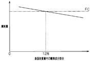
- FIG. 4 shows the relationship between the oxygen component ratio in the surface modified layer and the amount of wear.
- the relationship shown in the figure is obtained from the result of performing the LFW-1 test on a plurality of test pieces having different oxygen component ratios in the surface modified layer.
- the higher the oxygen component ratio in the surface modified layer the higher the wear resistance.
- the same wear resistance as that of cast iron (FC) can be obtained.
- the LFW-1 test is performed by pressing the block test piece 9 against the ring test piece 10 while applying a predetermined surface pressure P, and rotating the ring test piece 10 at a predetermined speed n. Done. Further, the surface pressure between the block test piece 9 and the ring test piece 10 is obtained from the measurement result of the pressing load by the load cell 11.
- the plasma irradiation treatment is performed by increasing the oxygen content of the carrier gas and the irradiation thermal energy per unit area in the order of higher wear resistance required. Is called.
- the higher the required wear resistance the higher the oxygen component ratio in the surface modified layer. Therefore, the wear resistance of each part of the piston sliding surface 3 is formed so as to satisfy the request for each part.
- the wear resistance can be made different for each part of the piston sliding surface 3 only by adjusting the oxygen content of the carrier gas and the irradiation heat energy per unit area during the plasma irradiation treatment. it can. Therefore, an aluminum alloy cylinder block having a piston sliding surface formed so that the wear resistance of each part satisfies the requirements of each part can be realized at low cost.
- both the oxygen content of the carrier gas and the irradiation heat energy per unit area during the plasma irradiation treatment are changed for each part of the piston sliding surface 3, but the per unit area Even if the irradiation heat energy is fixed and only the oxygen content of the carrier gas is changed, the wear resistance of each part of the piston sliding surface 3 can be varied.
- the portion that comes into sliding contact with the piston ring 7 when the piston 6 is located at the top dead center the portion that comes into sliding contact with the piston ring 7 when the piston 6 is located at the bottom dead center, and other piston rings
- the oxygen content of the carrier gas was decreased in the order of the sliding contact portion with 7 and the portion where only the skirt portion 8 of the piston 6 was in sliding contact.
- the order of the oxygen content rate of each part and the way of dividing the part may be changed as appropriate according to the demand. It ’s fine.
- the higher the wear resistance of the part the higher the oxygen content of the carrier gas and the plasma irradiation treatment is performed, so that the wear resistance of each part satisfies the requirements of each part.
- An aluminum alloy cylinder block having a piston sliding surface can be manufactured.
Landscapes
- Chemical & Material Sciences (AREA)
- Chemical Kinetics & Catalysis (AREA)
- Engineering & Computer Science (AREA)
- Materials Engineering (AREA)
- Mechanical Engineering (AREA)
- Metallurgy (AREA)
- Organic Chemistry (AREA)
- Cylinder Crankcases Of Internal Combustion Engines (AREA)
- Pistons, Piston Rings, And Cylinders (AREA)
Abstract
アルミニウム合金製シリンダーブロック(2)のピストン摺動面(3)にプラズマ照射処理を施すとともに、そのプラズマ照射処理に使用するキャリアーガスの酸素含有率をピストン摺動面(3)の部位毎に変化させることで、ピストン摺動面(3)の耐摩耗性を部位毎に異ならせるようにした。
Description
本発明は、アルミニウム合金製シリンダーブロックにおけるピストン摺動面の耐摩耗性を向上させるための表面改質方法に関するものである。
近年、エンジンの軽量化のため、鋳鉄からアルミニウム合金へのシリンダーブロック材料の置き換えが進められている。ただし、表面改質処理を経ていないアルミニウム合金は、鋳鉄に比して摩耗に弱く、シリンダーボア全面に必要な耐摩耗性を確保することはできない。そのため、アルミニウム合金製シリンダーブロックの製造では、耐摩耗性を向上するための表面改質処理をシリンダーボア全面に施すことが一般的となっている。そうした表面改質処理は、加熱した溶射材料の溶射処理や分散めっき処理、プラズマ照射処理などによって行われている。
一方、特許文献1に記載されているように、シリンダーボア全面にあっても、その部位毎に必要な耐摩耗性が異なっていることが知られている。例えばピストンが上死点に位置するときにピストンリングと摺接する部位や、ピストンが下死点に位置するときにピストンリングと摺接する部位、特に前者には、非常に高い耐摩耗性が要求される。一方、ピストンのスカート部としか摺接しない部位では、余り高い耐摩耗性は必要とされていない。そのため、シリンダーボア全面に一様な態様で表面改質処理を行うと偏摩耗が発生してしまう。また、本来、必要とされるよりも過大な耐摩耗性が付与されると、相手攻撃性が高くなり過ぎてしまい、摺動の相手部材であるピストンリングやピストンスカートの摩耗が増大してしまう。
そこで従来、部位毎に異なる態様で表面改質処理を行うアルミニウム合金製シリンダーブロックの表面改質方法が提案されている。例えば特許文献2及び3には、硬質粒子や自己潤滑性粒子、固体潤滑材の分散めっき処理によりピストン摺動面の改質処理を行うとともに、硬質粒子や自己潤滑性粒子、固体潤滑材の共析量、分散量を異ならせることで、耐摩耗性を部位毎に変えることが記載されている。
一方、特許文献4には、プラズマ溶射処理により形成されたシリンダーライナーをアルミニウム合金により鋳ぐるむことでシリンダーブロックを製造するとともに、溶射材料の成分を部位毎に異ならせることで、ピストン摺動面となるシリンダーライナー内周面の耐摩耗性を部位毎に変えることが記載されている。
更に特許文献5には、A390合金の連続鋳造材を押し出し鍛造することで形成されたシリンダーライナーを、アルミニウム合金により鋳ぐるむことでシリンダーブロックを製造することが記載されている。そして、シリンダーライナー内周面の一部に局所加熱によるリメルト処理を施すことで、ピストン摺動面となるシリンダーライナー内周面の耐摩耗性を部位毎に変えている。
これら従来の技術によっても、部位毎に耐摩耗性の異なったピストン摺動面を有したアルミニウム合金製シリンダーブロックを製造することが可能である。しかしながら、これら従来の技術では、製造コストの高騰は避けられないものとなっている。
例えば特許文献2及び3では、シリンダーボア全面に分散めっき処理を施しつつ、硬質粒子や自己潤滑性粒子、固体潤滑材の共析量、分散量を部位毎に異ならせなければならず、そのためには大掛かりで複雑なめっき装置を必要とする。またそれらの共析量、分散量の制御は難しく、各部位に必要な耐摩耗性を的確に付与することは困難となっている。
一方、特許文献4及び5に記載のものは、シリンダーライナーを別体形成する必要があり、それだけでも、シリンダーブロック全体を一体鋳造する場合に比してコストの掛かるものとなっている。その上、特許文献4のものでは、シリンダーライナー内周面の耐摩耗性を部位毎に異ならせるために、溶射材料の成分を部位毎に変える必要があり、その製造は容易ならざるものとなっている。一方、特許文献5のものでは、リメルト処理だけでは必要な耐摩耗性を確保することは困難であり、しかもシリンダーライナーを高価なA390合金で形成する必要があるものとなっている。
このように、従来にあっては、各部位の耐摩耗性が部位毎の要求を満すように形成されたピストン摺動面を有するアルミニウム合金製シリンダーブロックは、コストが高くつくものとなっている。そのため、そうしたアルミニウム合金製シリンダーブロックを低コストで実現可能な製造技術の確立が要望されている。
本発明は、こうした実情に鑑みてなされたものであり、その解決しようとする課題は、各部位の耐摩耗性が部位毎の要求を満すように形成されたピストン摺動面を有するアルミニウム合金製シリンダーブロックを低コストで実現可能なアルミニウム合金製シリンダーブロックの表面改質方法を提供することにある。
上記課題を解決するため、アルミニウム合金製シリンダーブロックのピストン摺動面の表面改質を行う方法としての本発明は、ピストン摺動面にプラズマ照射処理を施すとともに、そのプラズマ照射処理に使用するキャリアーガスの酸素含有率をピストン摺動面の部位毎に変化させるようにしている。
プラズマ照射処理に使用するキャリアーガスの酸素含有率を高めると、プラズマ照射処理により形成された表面改質層に含まれる硬質物の成分比が増加して耐摩耗性が向上する。そのため、プラズマ照射処理に際して、キャリアーガスの酸素含有率を部位毎に調整すれば、部位毎に耐摩耗性の異なったピストン摺動面を形成することができる。しかも、プラズマ照射中にキャリアーガスの酸素含有率を部位毎に調整するだけで、各部位の耐摩耗性を異ならせることができるため、部位毎に耐摩耗性の異なったピストン摺動面を有したアルミニウム合金製シリンダーブロックを低コストで製造することができる。したがって、本発明によれば、各部位の耐摩耗性が部位毎の要求を満すように形成されたピストン摺動面を有するアルミニウム合金製シリンダーブロックを低コストで実現することができる。
なお、一般に、ピストン摺動面においては、A.ピストンが上死点に位置するときにピストンリングと摺接する部位、B.ピストンが下死点に位置するときにピストンリングと摺接する部位、C.それら以外のピストンリングとの摺接部位、D.ピストンスカート部しか摺接しない部位の順に要求される耐摩耗性は低くなる。そのため、A→B→C→Dの順でキャリアーガスの酸素含有率を少なくすれば、各部位の耐摩耗性が部位毎の要求を満すように形成されたピストン摺動面を有するアルミニウム合金性シリンダーブロックを製造することができる。
また、プラズマ照射に際しての単位面積当りの照射熱エネルギーを増大させることでも、改質層の硬質物の成分比を増加させることができる。そのため、キャリアーガスの酸素含有率の変化とともに、単位面積当りの照射熱エネルギーを変化させるようにすれば、各部位の耐摩耗性をより的確に変化させることができる。
以下、本発明のアルミニウム合金製シリンダーブロックの表面改質方法を具体化した一実施の形態を、図1~図5を参照して詳細に説明する。
本実施の形態では、シリンダーブロックのピストン摺動面にプラズマ照射処理を施してその表面を改質している。図1に示すように、プラズマ照射処理は、シリンダーブロック2のピストン摺動面3から一定の距離だけ離れた位置に配置された電極1にキャリアーガスを供給しつつ、電極1とシリンダーブロック2との間に電圧を印加することで行われる。電極1には、酸素タンク4から送られた酸素と大気とを混合したガスがキャリアーガスとして供給され、キャリアーガスの酸素含有率は、バルブ5により調整されるようになっている。
また本実施の形態では、プラズマ照射処理に際して、キャリアーガスの酸素含有率、及び単位面積当りの照射熱エネルギーを、ピストン摺動面3の部位毎に変化させている。そしてこれにより、プラズマ照射処理によって改質された表面改質層の酸素成分割合を、ピストン摺動面3の部位毎に異ならせている。具体的には、図2に示す5つ部位A~Eの酸素成分割合を異ならせている。ここでの部位Aは、ピストン6が上死点に位置するときにピストンリング7と摺接する部位であり、部位Bは、ピストン6が下死点に位置するときにピストンリング7と摺接する部位である。また部位Cは、それら以外のピストンリング7との摺接部位であり、部位Dは、ピストン6のスカート部8としか摺接しない部位である。さらに部位Eは、ピストンリング7、スカート部8のいずれとも摺接しない非摺接部位となっている。
ここでは、下表1及び図3に示すように、各部位A~Dのキャリアーガスの酸素含有率、及び単位面積当りの照射熱エネルギーを設定している。なお、本実施の形態では、非摺接部位である部位Eには、プラズマ照射処理は割愛している。本実施の形態では、部位A→部位B→部位C→部位Dの順で、キャリアーガスの酸素含有率を小さくしている(c4>c3>c2>c1)。また同様に、部位A→部位B→部位C→部位Dの順で、単位面積当りの照射熱エネルギーを小さくしている(e4>e3>e2>e1)。そして本実施の形態では、部位Aの表面改質層内の酸素成分割合を30%、部位Bの表面改質層内の酸素成分割合を15%、部位Cの表面改質層内の酸素成分割合を12%、部位Dの表面改質層内の酸素成分割合を6%としている。なお、表面改質層内の酸素成分割合が高いほど、アルミナなどの硬質粒子がより多く表面改質層に形成されるようになる。

図4は、表面改質層内の酸素成分割合と摩耗量との関係を示している。同図に示される関係は、表面改質層内の酸素成分割合の異なる複数の試験片についてLFW-1試験を行った結果から求められている。同図4に示すように、表面改質層内の酸素成分割合が高いほど、耐摩耗性が向上される。また表面改質層内の酸素成分割合が12%以上であれば、鋳鉄(FC)と同程度の耐摩耗性が得られることが確認されている。なお、LFW-1試験は、図5に示すように、所定の面圧Pをかけながらブロック試験片9をリング試験片10に押し付けるとともに、リング試験片10を所定の速度nで回転させることで行われる。またブロック試験片9とリング試験片10との間の面圧は、ロードセル11による押し付け荷重の計測結果から求められるようになっている。
以上のような本実施の形態の表面改質方法では、必要とされる耐摩耗性がより高い順に、キャリアーガスの酸素含有率、単位面積当りの照射熱エネルギーを大きくしてプラズマ照射処理が行われる。そしてその結果、必要とされる耐摩耗性がより高い部位ほど、表面改質層内の酸素成分割合が高くされる。そのため、ピストン摺動面3の各部位の耐摩耗性が、部位毎の要求を満すように形成される。
以上説明した本実施の形態のアルミニウム合金製シリンダーブロックの表面改質方法によれば、次の効果を奏することができる。
(1)本実施の形態では、プラズマ照射処理に際してのキャリアーガスの酸素含有率、単位面積当りの照射熱エネルギーを調節するだけでピストン摺動面3の部位毎に耐摩耗性を異ならせることができる。そのため、各部位の耐摩耗性が部位毎の要求を満すように形成されたピストン摺動面を有するアルミニウム合金製シリンダーブロックを低コストで実現することができる。
なお、上記実施の形態は、次のように変更して実施することもできる。
・上記実施の形態では、プラズマ照射処理に際してのキャリアーガスの酸素含有率、及び単位面積当りの照射熱エネルギーの双方を、ピストン摺動面3の部位毎に変化させていたが、単位面積当りの照射熱エネルギーは固定して、キャリアーガスの酸素含有率のみを変化させるだけでも、ピストン摺動面3の各部位の耐摩耗性を異ならせることはできる。
・上記実施の形態では、ピストン6が上死点に位置するときにピストンリング7と摺接する部位、ピストン6が下死点に位置するときにピストンリング7と摺接する部位、それら以外のピストンリング7との摺接部位、ピストン6のスカート部8しか摺接しない部位の順に、キャリアーガスの酸素含有率を少なくしていた。もっとも、適用されるシリンダーブロックにおけるピストン摺動面の耐摩耗性の要求が異なる場合には、各部位の酸素含有率の高さの順序や部位の分け方は、その要求に応じて適宜変更すれば良い。いずれにせよ、高い耐摩耗性が要求される部位ほど、キャリアーガスの酸素含有率を高くしてプラズマ照射処理を行えば、各部位の耐摩耗性が部位毎の要求を満すように形成されたピストン摺動面を有するアルミニウム合金製シリンダーブロックを製造することができる。
1…電極、2…シリンダーブロック、3…ピストン摺動面、4…酸素タンク、5…バルブ、6…ピストン、7…ピストンリング、8…スカート部、9…ブロック試験片、10…リング試験片、11…ロードセル、A…ピストンが上死点に位置するときにピストンリングと摺接する部位、B…ピストンが下死点に位置するときにピストンリングと摺接する部位、C…それら以外のピストンリングとの摺接部位、D…ピストンのスカート部しか摺接しない部位、E…非摺接部位。
Claims (3)
- アルミニウム合金製シリンダーブロックのピストン摺動面の表面改質を行う方法であって、
前記ピストン摺動面にプラズマ照射処理を施すとともに、そのプラズマ照射処理に使用するキャリアーガスの酸素含有率を前記ピストン摺動面の部位毎に変化させる
ことを特徴とするアルミニウム合金製シリンダーブロックの表面改質方法。 - ピストンが上死点に位置するときにピストンリングと摺接する部位、同ピストンが下死点に位置するときに前記ピストンリングと摺接する部位、それら以外の前記ピストンリングとの摺接部位、前記ピストンのスカート部しか摺接しない部位の順に、前記キャリアーガスの酸素含有率を少なくする
ことを特徴とする請求項1に記載のアルミニウム合金製シリンダーブロックの表面改質方法。 - 前記キャリアーガスの酸素含有率の変化とともに、単位面積当りの照射熱エネルギーを変化させる
請求項1又は2に記載のアルミニウム合金製シリンダーブロックの表面改質方法。
Priority Applications (1)
| Application Number | Priority Date | Filing Date | Title |
|---|---|---|---|
| PCT/JP2011/061892 WO2012160654A1 (ja) | 2011-05-24 | 2011-05-24 | アルミニウム合金製シリンダーブロックの表面改質方法 |
Applications Claiming Priority (1)
| Application Number | Priority Date | Filing Date | Title |
|---|---|---|---|
| PCT/JP2011/061892 WO2012160654A1 (ja) | 2011-05-24 | 2011-05-24 | アルミニウム合金製シリンダーブロックの表面改質方法 |
Publications (1)
| Publication Number | Publication Date |
|---|---|
| WO2012160654A1 true WO2012160654A1 (ja) | 2012-11-29 |
Family
ID=47216757
Family Applications (1)
| Application Number | Title | Priority Date | Filing Date |
|---|---|---|---|
| PCT/JP2011/061892 Ceased WO2012160654A1 (ja) | 2011-05-24 | 2011-05-24 | アルミニウム合金製シリンダーブロックの表面改質方法 |
Country Status (1)
| Country | Link |
|---|---|
| WO (1) | WO2012160654A1 (ja) |
Citations (4)
| Publication number | Priority date | Publication date | Assignee | Title |
|---|---|---|---|---|
| JP2005298884A (ja) * | 2004-04-09 | 2005-10-27 | Nissan Motor Co Ltd | 溶射皮膜気孔率調整方法およびこの方法によってシリンダボア内面の気孔率を調整したエンジンのシリンダブロック |
| JP2006144574A (ja) * | 2004-11-16 | 2006-06-08 | Aisin Seiki Co Ltd | ピストン |
| JP2007332993A (ja) * | 2006-06-12 | 2007-12-27 | Kyushu Institute Of Technology | 固体潤滑軸受 |
| JP2009079488A (ja) * | 2007-09-25 | 2009-04-16 | Riken Corp | アルミニウム合金製バルブスプリングリテーナ |
-
2011
- 2011-05-24 WO PCT/JP2011/061892 patent/WO2012160654A1/ja not_active Ceased
Patent Citations (4)
| Publication number | Priority date | Publication date | Assignee | Title |
|---|---|---|---|---|
| JP2005298884A (ja) * | 2004-04-09 | 2005-10-27 | Nissan Motor Co Ltd | 溶射皮膜気孔率調整方法およびこの方法によってシリンダボア内面の気孔率を調整したエンジンのシリンダブロック |
| JP2006144574A (ja) * | 2004-11-16 | 2006-06-08 | Aisin Seiki Co Ltd | ピストン |
| JP2007332993A (ja) * | 2006-06-12 | 2007-12-27 | Kyushu Institute Of Technology | 固体潤滑軸受 |
| JP2009079488A (ja) * | 2007-09-25 | 2009-04-16 | Riken Corp | アルミニウム合金製バルブスプリングリテーナ |
Similar Documents
| Publication | Publication Date | Title |
|---|---|---|
| RU2544332C2 (ru) | Поршневое кольцо с покрытием, нанесенным путем термического напыления, и способ его получения | |
| CN102046824B (zh) | 阀座用铁基烧结合金以及内燃机用阀座 | |
| CN1311145C (zh) | 烧结合金阀座及其制造方法 | |
| US9487855B2 (en) | Wear protection layer for piston rings | |
| RU2661352C2 (ru) | Способ изготовления поршневого кольца | |
| KR20140129769A (ko) | 알루미늄 피스톤의 국부강화용 알루미늄합금 조성물 및, 이 조성물을 이용한 국부강화층이 형성된 알루미늄 피스톤 | |
| JP6871361B2 (ja) | 熱伝導性に優れた内燃機関用鉄基焼結合金製バルブシート | |
| JP6276929B2 (ja) | 軸受部品及び溶射法 | |
| CN105452507B (zh) | 烧结合金制阀导承及其制造方法 | |
| CN104279019B (zh) | 气门座及其制造方法 | |
| US20140225330A1 (en) | Piston ring | |
| RU2009143528A (ru) | Деталь машины для пары скольжения, а также способ ее изготовления | |
| US20190001447A1 (en) | Method of manufacturing high-conductivity wear resistant surface on a soft substrate | |
| CN1153846C (zh) | 一种保护薄层的生成方法及具有至少一件有一保护薄层的构件的机器 | |
| EP3051157B1 (en) | Sliding member | |
| KR20190013753A (ko) | 밸브 시트 링 | |
| JP2015059544A (ja) | シリンダボアとピストンリングの組合せ | |
| JP7219776B2 (ja) | ピストンリング | |
| CN104603317B (zh) | 用于活塞环的耐磨涂层 | |
| WO2012160654A1 (ja) | アルミニウム合金製シリンダーブロックの表面改質方法 | |
| CN105296878A (zh) | 铝基活塞环槽表面合金强化方法 | |
| JP7258601B2 (ja) | 熱引け性に優れた内燃機関用鉄基焼結合金製バルブシート | |
| CN103124842B (zh) | 往复活塞式内燃机曲轴箱的支承座中的通风孔的制造方法 | |
| US20170130307A1 (en) | Alloy composition for thermal spray application | |
| JP2013148026A (ja) | シリンダライナ |
Legal Events
| Date | Code | Title | Description |
|---|---|---|---|
| 121 | Ep: the epo has been informed by wipo that ep was designated in this application |
Ref document number: 11866421 Country of ref document: EP Kind code of ref document: A1 |
|
| NENP | Non-entry into the national phase |
Ref country code: DE |
|
| 122 | Ep: pct application non-entry in european phase |
Ref document number: 11866421 Country of ref document: EP Kind code of ref document: A1 |
|
| NENP | Non-entry into the national phase |
Ref country code: JP |