WO2012157292A1 - レンズユニットの製造方法、及びレンズアレイユニットの製造方法 - Google Patents
レンズユニットの製造方法、及びレンズアレイユニットの製造方法 Download PDFInfo
- Publication number
- WO2012157292A1 WO2012157292A1 PCT/JP2012/051487 JP2012051487W WO2012157292A1 WO 2012157292 A1 WO2012157292 A1 WO 2012157292A1 JP 2012051487 W JP2012051487 W JP 2012051487W WO 2012157292 A1 WO2012157292 A1 WO 2012157292A1
- Authority
- WO
- WIPO (PCT)
- Prior art keywords
- adhesive
- lens
- lens array
- region
- adhesion
- Prior art date
- Legal status (The legal status is an assumption and is not a legal conclusion. Google has not performed a legal analysis and makes no representation as to the accuracy of the status listed.)
- Ceased
Links
Images













Classifications
-
- G—PHYSICS
- G02—OPTICS
- G02B—OPTICAL ELEMENTS, SYSTEMS OR APPARATUS
- G02B3/00—Simple or compound lenses
- G02B3/0006—Arrays
-
- B—PERFORMING OPERATIONS; TRANSPORTING
- B29—WORKING OF PLASTICS; WORKING OF SUBSTANCES IN A PLASTIC STATE IN GENERAL
- B29D—PRODUCING PARTICULAR ARTICLES FROM PLASTICS OR FROM SUBSTANCES IN A PLASTIC STATE
- B29D11/00—Producing optical elements, e.g. lenses or prisms
- B29D11/00009—Production of simple or compound lenses
- B29D11/00278—Lenticular sheets
- B29D11/00307—Producing lens wafers
-
- G—PHYSICS
- G02—OPTICS
- G02B—OPTICAL ELEMENTS, SYSTEMS OR APPARATUS
- G02B7/00—Mountings, adjusting means, or light-tight connections, for optical elements
- G02B7/02—Mountings, adjusting means, or light-tight connections, for optical elements for lenses
- G02B7/021—Mountings, adjusting means, or light-tight connections, for optical elements for lenses for more than one lens
-
- G—PHYSICS
- G02—OPTICS
- G02B—OPTICAL ELEMENTS, SYSTEMS OR APPARATUS
- G02B7/00—Mountings, adjusting means, or light-tight connections, for optical elements
- G02B7/02—Mountings, adjusting means, or light-tight connections, for optical elements for lenses
- G02B7/025—Mountings, adjusting means, or light-tight connections, for optical elements for lenses using glue
Definitions
- the present invention relates to a method for manufacturing a lens unit and a method for manufacturing a lens array unit.
- an imaging lens (lens unit) described in Patent Document 1 first, wafer lenses 1 and 3 having a plurality of resin lens portions 13 and 14 provided on both surfaces of a glass substrate 10 are manufactured. Next, the wafer lenses 1 and 3 are stacked via the spacer 2. Wafer lenses 1 and 3 and spacer 2 are fixed by an adhesive dropped on the bonding portion to obtain a lens array unit, and thereby a sealed space sealed by wafer lenses 1 and 3 and spacer 2 Is formed (see FIG. 1B of Patent Document 1). Thereafter, each lens unit is divided into individual pieces to obtain a plurality of imaging lenses (lens units). At this time, since there is a possibility of affecting the performance of the lens unit, it is necessary to prevent foreign matters (dust, water, etc.) from entering the sealed space.
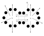
- FIG. 31A to FIG. 31C show an example in which an adhesive is dropped and arranged in a dot shape, and is a view of the lens array (FIG. 31C is a lens unit) viewed from the optical axis direction of the lens.
- 31B and 31C show a state in which the other lens array is pressed against one lens array, but the other lens array is not shown in the drawing.
- Each lens array is provided with a concave lens portion L, and each concave lens portion L is opposed to form a space (a sealed space after being joined).
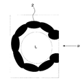
- each lens portion L is cut in such a state (see FIG. 31C), there is a problem that cutting fluid or water enters the space from the unsealed portion ⁇ and affects the performance of the lens unit. . Since the unsealed part is surrounded by the lens part and the adhesive 2, the adhesive 2 cannot be additionally applied before cutting.
- an object of the present invention is to provide a lens unit manufacturing method and a lens array unit manufacturing method capable of obtaining a lens unit and a lens array unit with few sealing defects in order to solve the above problems. To do.
- the method of manufacturing a lens unit according to claim 1 includes a dropping step, a sealing space forming step, and a cutting step.
- the dropping step is performed by adhering to at least one of an adhesion region on the first lens array having a plurality of lens portions arranged two-dimensionally and an adhesion region on an opposing member provided to face the first lens array.
- the agent is dropped at a plurality of locations.
- both the adhesive regions are opposed to each other, and at least one of the first lens array and the facing member is pressed against the other, thereby joining the first lens array and the facing member, and a plurality of lenses.
- a sealed space is formed for each part.
- the bonded first lens array and the opposing member are cut in units of sealing space.
- the adhesive dripping conditions for the first adhesive region set at a position corresponding to the plurality of lens portions in the adhesive region, and the adhesive dripping for the other second adhesive regions.
- the plurality of adhesives in the first adhesive region are connected before the plurality of adhesives in the second adhesive region at the time of pressing in the sealed space forming step.
- the lens unit manufacturing method according to claim 2 is the lens unit manufacturing method according to claim 1, wherein the first lens array surrounds each of the plurality of lens portions.
- the lens unit manufacturing method according to claim 3 is the lens unit manufacturing method according to claim 1, wherein the opposing member is joined to the first lens array.
- a protrusion that surrounds each of the plurality of lens portions and has an adhesive region on the top thereof is provided. In the sealing space forming step, the first lens array and the top of the protrusion are joined, so that the protrusion forms a side wall of the sealing space.
- a method for manufacturing a lens unit according to claim 4 is the method for manufacturing a lens unit according to claim 1, wherein the first lens array surrounds each of a plurality of lens portions. And a first protrusion having an adhesive region on its top, and the opposing member surrounds each of the plurality of lens portions when joined to the first lens array and has an adhesive region on its top. Two protrusions are provided. Then, in the sealing space forming step, the top of the first protrusion and the top of the two protrusions are joined, so that the first protrusion and the second protrusion form a side wall of the sealing space.
- the manufacturing method of the lens unit of Claim 5 has a dripping step, a sealing space formation step, and a cutting
- the dropping step includes an adhesion region on the first lens array having a plurality of lens portions arranged two-dimensionally, an adhesion region on an opposing member provided to face the first lens array, and the first lens array.
- a bonding region provided on both surfaces of a spacer substrate having a plurality of holes for receiving a plurality of lens portions when the first lens array is disposed between the opposing members and the first lens array; Adhesive is applied to a plurality of locations for at least one of the adhesion area of one lens array and the adhesion area of one side of the spacer substrate and at least one of the adhesion area of the opposing member and the adhesion area of the other side of the spacer substrate. Dripping.
- the adhesive region of the first lens array and the adhesive region on one side of the spacer substrate are opposed to each other, at least one of the first lens array and the spacer substrate is pressed against the other, and the opposing member The adhesive region and the adhesive region on the other surface side of the spacer substrate are opposed to each other, and at least one of the opposing member and the spacer substrate is pressed against the other, thereby joining the first lens array, the opposing member, and the spacer substrate.
- a sealing space is formed for each lens portion.
- the cutting step the bonded first lens array, the facing member, and the spacer substrate are cut in units of sealing space.
- the adhesive dripping conditions for the first adhesive region at a position corresponding to the position between the plurality of lens portions in the adhesive region, and the adhesive dripping conditions for the other second adhesive regions are set.
- the plurality of adhesives in the first adhesive region are connected before the plurality of adhesives in the second adhesive region at the time of pressing.
- a manufacturing method of the lens unit according to claim 6 is the manufacturing method of the lens unit according to claim 1 or 5, wherein the bonding in the first bonding region is performed in the dropping step.
- the interval between the agents is made smaller than the interval between the adhesives in the second adhesive region.
- the manufacturing method of the lens unit according to claim 7 is the manufacturing method of the lens unit according to claim 1 or 5, wherein the dropping condition is an interval of the dropping position of the adhesive. including. And the space
- region are changed.
- the invention described in claim 7 can be applied to the invention described in any one of claims 2 to 4 and 6.
- the lens unit manufacturing method according to claim 8 is the lens unit manufacturing method according to claim 1 or 5, wherein the first adhesion region includes at least three lenses. A region surrounded by the portion, and a region between two adjacent lens portions. And the space
- the manufacturing method of the lens unit of Claim 9 is a manufacturing method of the lens unit of Claim 1 or 5, Comprising: Dropping conditions contain the dripping amount of an adhesive agent. .
- a lens unit manufacturing method according to a tenth aspect is the lens unit manufacturing method according to the first or fifth aspect, wherein the opposing member is a plate-like member.
- the invention described in claim 10 can be applied to the invention described in any one of claims 2 to 4 and 6 to 9.
- the lens unit manufacturing method according to claim 11 is the lens unit manufacturing method according to claim 1 or 5, wherein the opposing members are two-dimensionally arranged.
- the manufacturing method of the lens array unit of Claim 12 has a dripping step and a sealing space formation step.
- the dropping step is performed by adhering to at least one of an adhesion region on the first lens array having a plurality of lens portions arranged two-dimensionally and an adhesion region on an opposing member provided to face the first lens array.
- the agent is dropped at a plurality of locations.
- both the adhesive regions are opposed to each other, and at least one of the first lens array and the facing member is pressed against the other, thereby joining the first lens array and the facing member, and a plurality of lenses.
- a sealed space is formed for each part.
- the adhesive dripping conditions for the first adhesive region set at a position corresponding to the plurality of lens portions in the adhesive region, and the adhesive dripping for the other second adhesive regions.
- the plurality of adhesives in the first adhesive region are connected before the plurality of adhesives in the second adhesive region at the time of pressing in the sealed space forming step.
- the lens array unit manufacturing method includes a dropping step and a sealing space forming step.
- the dropping step includes an adhesion region on the first lens array having a plurality of lens portions arranged two-dimensionally, an adhesion region on an opposing member provided to face the first lens array, and the first lens array.
- a bonding region provided on both surfaces of a spacer substrate having a plurality of holes for accommodating each of the plurality of lens portions when disposed between the opposing member and being joined to the first lens array; Adhesive is applied to a plurality of locations for at least one of the adhesion area of one lens array and the adhesion area of one side of the spacer substrate and at least one of the adhesion area of the opposing member and the adhesion area of the other side of the spacer substrate. Dripping.
- the adhesive region of the first lens array and the adhesive region on one side of the spacer substrate are opposed to each other, at least one of the first lens array and the spacer substrate is pressed against the other, and the opposing member
- the adhesive region and the adhesive region on the other surface side of the spacer substrate are opposed to each other, and at least one of the opposing member and the spacer substrate is pressed against the other, thereby joining the first lens array, the opposing member, and the spacer substrate.
- a sealing space is formed for each lens portion.
- a method for manufacturing a lens array unit according to claim 14 is the method for manufacturing a lens array unit according to claim 12 or 13, wherein in the dropping step, in the first adhesion region.
- the adhesive interval is made smaller than the adhesive interval in the second adhesive region.
- the adhesive dropping condition for the first adhesive region set at a position corresponding to the plurality of lens portions, and the adhesive dropping condition for the other second adhesive region. And different.
- the sealing space step when the lens array and the opposing member are pressed, the plurality of adhesives in the first adhesive region are connected before the plurality of adhesives in the second adhesive region. For this reason, it can prevent that the adhesive agent dripped between several lens parts is pushed with the gas which escapes outside from the space formed for every lens part, and the said spaces connect. Therefore, it is possible to manufacture a lens unit with few sealing defects.
- FIG. 10 is a diagram showing a configuration of a first lens array according to Modification 2.
- FIG. 10 is a diagram showing a configuration of a first lens array according to Modification 2.
- FIG. 10 is a diagram showing a configuration of a first lens array according to Modification 2.
- FIG. 10 is a diagram showing a configuration of a first lens array according to Modification 2. It is a figure for demonstrating the conventional subject. It is a figure for demonstrating the conventional subject. It is a figure for demonstrating the conventional subject. It is a figure for demonstrating the conventional subject.
- the first lens array IM1 is configured to have four lens portions La arranged in a two-dimensional matrix (FIG. 4 shows the first lens array IM1 viewed from the side. Since only the two lens portions La are shown). Further, as a facing member provided to face the first lens array IM1, as shown in FIG. 6, a configuration having four lens portions Lb arranged in a two-dimensional matrix (second lens array IM2, FIG. 6). Since the second lens array IM2 is viewed from the side, only two lens portions Lb are described.
- FIG. 1 is a flowchart showing a molding process of the lens array according to this embodiment.
- molds upper mold 12 and lower mold 22
- the structure of the mold and the first lens array IM1 viewed from the side will be described.
- the upper mold 12 includes a bottom plate 4, a spacer 5, a core support member 11, and a core 13.
- the bottom plate 4 is a plate-like member that covers the upper bottom of the upper mold 12.
- the spacer 5 adjusts the protruding amount of the core 13.
- the core support member 11 is provided in the upper mold 12 and supports the core 13.
- the core 13 has a transfer surface 13a (in this embodiment, a convex shape), and the shape is transferred by being pressed against the glass GL.
- four core support members 11 and four cores 13 are provided.
- the cores 13 are arranged in a matrix on the lower surface 12 b of the upper mold 12.
- the lower mold 22 includes a bottom plate 4, a spacer 5, a core support member 21, and a core 23.
- the bottom plate 4 is a plate-like member that covers the lower bottom of the lower mold 22.
- the spacer 5 adjusts the protruding amount of the core 23.
- the core support member 21 is provided in the lower mold 22 and supports the core 23.
- the core 23 has a transfer surface 23a (in this embodiment, a concave shape), and the shape is transferred by being pressed against the glass GL.
- four core support members 21 and four cores 23 are provided.
- the cores 23 are arranged in a matrix on the upper surface 22 b of the lower mold 22.
- the lower mold 22 is positioned below the platinum nozzle NZ communicating with a storage unit (not shown) for storing the molten glass GL. Then, droplets of glass GL melted from the platinum nozzle NZ are collectively dropped onto the upper surface 22b of the lower mold 22 (S10). In such a state, since the viscosity of the glass GL is low, the dropped glass GL spreads on the upper surface 22 b and easily enters the transfer surface 23 a of the core 23. Thereby, the shape of the transfer surface 23a is transferred to the glass GL (S11).
- the lower mold 22 to which the glass GL is dropped in S10 is moved to a position below the upper mold 12 before the glass GL is cooled, so that the upper mold 12 and the lower mold 22 are opposed to each other. Then, the upper mold 12 and the lower mold 22 are aligned using a positioning guide (not shown) (S12).
- the upper mold 12 and the lower mold 22 are brought close to each other to form the glass GL.
- the shape of the transfer surface 13a of the core 13 is transferred to the glass GL (S13).
- the lower surface 12b of the upper mold 12 and the upper surface 22b of the lower mold 22 are held so as to be separated from each other by a predetermined distance to cool the glass GL.
- the glass GL solidifies in a state where it goes around and covers the tapered portion 22g.
- the first lens array IM1 is molded by separating the upper mold 12 and the lower mold 22 and taking out the glass GL (S14).
- the second lens array IM2 is molded by the same method.
- the first lens array IM1 includes a concave optical surface IM1b transferred and molded by the transfer surface 13a of the upper mold 12 and a convex optical surface transferred and formed by the transfer surface 23a of the lower mold 22.
- IM1e The concave optical surface IM1b and the convex optical surface IM1e constitute the lens portion La.
- the second lens array IM2 has a concave optical surface IM2b transferred and molded by the transfer surface 13a of the upper mold 12, and a convex optical surface IM2e transferred and formed by the transfer surface 23a of the lower mold 22.
- the concave optical surface IM2b and the convex optical surface IM2e constitute the lens portion Lb (see FIG. 6).
- the first lens array IM1 and the second lens array IM2 have the same shape, but may have different shapes.
- FIG. 5 is a flowchart showing manufacturing steps of the lens unit 1 according to this embodiment.
- the molded first lens array IM1 is held by the jig JZ, and the adhesive 2 is dropped onto the surface IM1a of the first lens array IM1 (S20).
- the adhesive 2 is dropped at a plurality of locations on the surface IM1a by a dropping device (not shown).
- the nozzle of the dropping device (not shown) is brought close to the surface IM1a of the first lens array IM1, which is the dropping target, so that the adhesive contacts both the nozzle and the surface IM1a.
- the present invention is not limited to this, and the adhesive may be discharged so that the adhesive is separated from the nozzle when the adhesive reaches the surface IM1a.
- S20 is an example of the “dropping step” in the present embodiment.
- the surface IM1a and the surface IM2a are examples of the “adhesion region” in the present embodiment.
- SH is arranged (see FIG. 6).
- the adhesive for example, a photocurable adhesive or a thermosetting adhesive made of an ene-thiol resin, an epoxy resin, an acrylic resin, or the like is used.
- the adhesive has a viscosity in a dropping environment. 100 to 2000 mPa ⁇ s is used. If the viscosity is less than 100 mPa ⁇ s, the adhesives are immediately connected after dropping, and the spread of the adhesive during pressing as described later may not be well controlled, or the adhesive may not be sufficiently spread. is there. When the viscosity exceeds 2000 mPa ⁇ s, it is difficult to discharge the adhesive from the nozzle, which may make it unsuitable for manufacturing a small-diameter lens unit.
- dropping is performed in a room temperature environment, and a polyene-polythiol-based adhesive having a UV (Ultra Violet) curing property (viscosity of 300 mPa ⁇ s at room temperature) is used as the adhesive 2.
- a polyene-polythiol-based adhesive having a UV (Ultra Violet) curing property viscosity of 300 mPa ⁇ s at room temperature
- the first lens array IM1 and the second lens array IM2 are passed through the surfaces IM1a and IM2a.
- the lens array IM2 is joined (S21).
- the first lens array IM1 and the second lens array IM2 are joined by irradiating ultraviolet rays with UV illumination (not shown) or the like to cure the adhesive. In this way, the lens array unit IM3 is obtained.
- the concave optical surface IM1b molded on the first lens array IM1 and the concave optical surface IM2b molded on the second lens array IM2 form a sealed space.
- S21 is an example of a “sealed space forming step” in the present embodiment.
- the “sealing space” refers to a space (concave optical surface IM1b and concave optical surface IM2b) sealed with the first lens array IM1, the opposing member (second lens array IM2), and an adhesive. Is a space isolated from the outside).
- the lens array unit IM3 is removed from the jig JZ, and the lens array unit IM3 is cut in units of sealing space by the dicing blade DB (S22).
- “Cutting in units of sealing spaces” means separating each sealing space in a state where the respective sealing spaces are held.
- the lens unit 1 as shown in FIG. 9 is completed (S23. Only one lens unit 1 is shown in FIG. 9). In the present embodiment, four lens units 1 can be obtained from the lens array unit IM3.
- S22 is an example of a “cutting step” in the present embodiment.
- FIG. 10 to FIG. 14 are views of the first lens array IM1 as viewed from the concave optical surface IM1b side.
- FIGS. 12 to 14 show a state where the concave optical surface IM1b of the first lens array IM1 and the concave optical surface IM2b of the second lens array IM2 are pressed. The description of IM2 is omitted.
- an adhesion region E is set in advance around the four lens portions La (concave optical surface IM1b).
- the adhesion area E includes an adhesion area E1 (first adhesion area E1) set between the plurality of lens portions La and another adhesion area E2 (second adhesion area E2).
- the adhesion region E1 is a region set in a polygon formed by an outer tangent among tangents in contact with both adjacent lens portions La.
- the adhesion region E1 is a region (in this embodiment, a region surrounded by four lens portions La) E11 surrounded by at least three lens portions La, and a region (this embodiment) sandwiched between two adjacent lens portions La.
- four regions) E12 are included.
- the region E12 is a region surrounded by a tangent line that is in contact with both adjacent lens portions La, and is an arbitrary region excluding the region E11.
- the dropping condition of the adhesive 2 with respect to the first adhesive region E1 at a position corresponding to the position between the plurality of lens portions La, and the adhesive 2 with respect to the other second adhesive region E2 The dripping conditions are different.
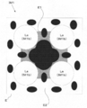
- the “dropping position” refers to a vertically lower position of the nozzle tip of a dropping device (not shown).
- the distance (p11, p12) between the dropping positions of the adhesive 2 in the first adhesive area E1 is the distance between the dropping positions of the adhesive 2 in the second adhesive area E2 ( Narrower than p2). Furthermore, in this embodiment, as shown in FIG. 11, the interval p11 of the dropping position of the adhesive 2 in the region E11 is made smaller than the interval p12 of the dropping position of the adhesive 2 in the region E12.
- the dropping device moves relative to the first lens array IM1 while changing the moving pitch with respect to the first lens array IM1, and drops the adhesive 2 at a plurality of locations.
- the dripping amount (diameter size) of each adhesive 2 shall be substantially uniform. For this reason, the intervals e11 and e12 of the adhesives 2 in the region E11 are smaller than the intervals e2 of the adhesives 2 in the region E12.
- the adhesive 2 After the adhesive 2 is dropped in this way, when the other is pressed against one of the first lens array IM1 and the second lens array IM2, the adhesive 2 spreads on the surface IM1a. And as shown in FIG. 12, the adjacent adhesives 2 are connected in order from the area
- the adhesive 2 arranged in the region E12 spreads while being connected along the circumference of the concave optical surface IM1b.
- the gas in the space formed by the concave optical surface IM1b and the concave optical surface IM2b moves from the portion where the adhesive 2 is not connected (in the direction of the arrow in FIG. 13) to the outside. Run away.
- the adhesives 2 in the region E11 are already connected to each other, and the part where the adhesives 2 are connected is pushed away by the gas so that the spaces around the adjacent lens parts do not communicate with each other. Accordingly, the spaces formed by the concave optical surface IM1b and the concave optical surface IM2b are not connected to each other, and a sealed space S in which each lens portion La is sealed is formed (see FIG. 14).
- the configuration in which the adhesive is dropped only on the surface IM1a of the first lens array IM1 has been described, but the target to which the adhesive is dropped is not limited to this.
- a configuration in which the adhesive is dropped only on the surface IM2a of the second lens array IM2 may be employed.
- the structure by which an adhesive agent is dripped at both surface IM1a and surface IM2a may be sufficient.
- the adhesive dropped onto both the surfaces IM1a and IM2a may be dropped so as to satisfy the above relationship when viewed from the optical axis direction of the lens.
- the second lens array IM2 is used as the counter member, but the present invention is not limited to this.
- a plate-like member in which no lens part is formed can be used as the opposing member.
- a sealing space is formed by the concave optical surface IM1b of the first lens array IM1 and the plate member.
- the adhesive 2 may be dropped on the plate-like member side.
- the first adhesion region E1 is located at a position corresponding to the position between the plurality of lens portions La (on the plate-like member facing the plurality of lens portions La when the first lens array IM1 and the facing member are joined). Position).
- the manufacturing method of the lens unit according to the present embodiment includes a dropping step, a sealing space forming step, and a cutting step.
- the adhesive 2 is dropped at a plurality of locations on the adhesive region E (E1, E2) on the first lens array IM1 having a plurality of lens portions La arranged two-dimensionally.
- the sealing space forming step the adhesion region E and the adhesion region on the second lens array IM2 provided to face the first lens array IM1 are opposed to each other, and at least the first lens array IM1 and the second lens array IM2 By pressing one against the other, the first lens array IM1 and the second lens array IM2 are joined to form a sealing space for each of the plurality of lens portions La.
- the joined first lens array IM1 and second lens array IM2 are cut in units of sealing space. Further, in the dropping step, the dropping condition of the adhesive 2 with respect to the first bonding area E1 set at a position corresponding to the position between the plurality of lens portions La in the bonding area, and the second bonding area E2 other than that.
- the sealing space forming step the plurality of adhesives 2 in the first adhesive region E1 are ahead of the plurality of adhesives 2 in the second adhesive region E2 at the time of pressing. It leads to.
- the lens array unit manufacturing method includes a dropping step and a sealed space forming step.
- the dropping step includes an adhesion region E (E1, E2) on the first lens array IM1 having a plurality of lens portions La arranged two-dimensionally, and a second lens array provided to face the first lens array IM1.
- the adhesive 2 is dropped at a plurality of locations on at least one of the adhesion regions E on the IM2.
- both the adhesion regions E are opposed to each other, and at least one of the first lens array IM1 and the second lens array IM2 is pressed against the other, thereby the first lens array IM1 and the second lens.
- the array IM2 is joined to form a sealing space for each of the plurality of lens portions La. Furthermore, in the dropping step, the dropping condition of the adhesive 2 with respect to the first bonding area E1 set at a position corresponding to the plurality of lens portions La in the bonding area E, and the other second bonding area E2 In the sealing space forming step, the plurality of adhesives 2 in the first adhesive region E1 is more than the plurality of adhesives 2 in the second adhesive region E2 at the time of pressing. Connect first.
- the interval (e11, e12) of the adhesive 2 in the first adhesive region E1 is made smaller than the interval (e2) of the adhesive 2 in the second adhesive region E2.
- the dropping condition according to the present embodiment includes the interval between the dropping positions of the adhesive 2.
- the first adhesion region E1 includes a region E11 surrounded by at least three lens portions La and a region E12 between two adjacent lens portions La, and is surrounded by at least three lens portions La.
- the distance e11 (p11) of the adhesive 2 in the area E11 is smaller than the distance e12 (p12) of the adhesive 2 in the area E12 between two adjacent lens portions La.
- the adhesive dripping conditions for the first adhesive region set at a position corresponding to the plurality of lens portions and the adhesive dripping conditions for the other second adhesive regions are set.
- the sealing space step the plurality of adhesives in the first adhesive region is bonded to the plurality of adhesives in the second adhesive region when the one lens array and the other lens array that is the opposing member are pressed. Connect before the agent. For this reason, the adhesive dripped between the plurality of lens portions is not prevented from being pushed and connected by the gas escaping from the space formed for each lens portion to the outside. Accordingly, it is possible to manufacture a lens unit and a lens array unit that have few sealing defects that cause an intrusion of cutting fluid or the like when being separated into pieces by cutting.
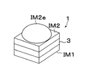
- the lens unit 1 including the spacer substrate 3 as shown in FIG. 15 is manufactured.
- the first lens array IM1 has a configuration having four lens portions La arranged in a two-dimensional matrix.
- a configuration (second lens array IM2) having four lens portions Lb arranged in a two-dimensional matrix is used as shown in FIG.
- Detailed description of the same parts as in the first embodiment, such as the molding method of the first lens array IM1 and the second lens array IM2 will be omitted.
- FIG. 15 is a perspective view of the spacer substrate 3.
- the spacer substrate 3 is disposed between the first lens array IM1 and the second lens array IM2 (opposing member).
- the spacer substrate 3 has a plurality of hole portions 3a in which a plurality of lens portions La (lens portions Lb) are accommodated when bonded to the first lens array IM1 (second lens array IM2). That is, the plurality of lens portions La (lens portions Lb) and the plurality of hole portions 3a correspond one-to-one, and each lens portion La (lens portion Lb) is accommodated in the corresponding hole portion 3a.
- four hole portions 3a for four lens portions La (lens portions Lb) are provided.
- FIG. 16 is a flowchart showing manufacturing steps of the lens unit 1 according to this embodiment.
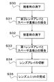
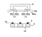
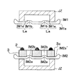
- 17 to 21 are views of the first lens array IM1 (second lens array IM2, spacer substrate 3) viewed from the side.
- the adhesive 2 is dropped on the surface 3b of the spacer substrate 3 (S30).
- the adhesive 2 is dropped at a plurality of locations on the surface 3b by a dropping device (not shown) or the like.
- a method similar to that of the first embodiment can be used as a method for dropping the adhesive 2.
- S30 is an example of the “dropping step” in the present embodiment.
- the surface 3b and the surface IM2a ′ are examples of the “adhesion region” in the present embodiment.
- the molded second lens array IM2 is held by the jig JZ, and the surface 3b of the spacer substrate 3 and the surface IM2a ′ of the second lens array IM2 are opposed to each other (see FIG. 17).
- the adhesive 2 spreads on the surface 3b by pressing at least one of the spacer substrate 3 and the second lens array IM2 against the other. Then, the spacer substrate 3 and the second lens array IM2 are bonded by ultraviolet irradiation through the surface 3b and the surface IM2a ′ (S31).
- the adhesive 2 is dropped onto the surface 3c of the spacer substrate 3 (S32).
- the adhesive 2 is dropped at a plurality of locations on the surface 3c by a dropping device (not shown) or the like.
- a method similar to that of the first embodiment can be used as a method for dropping the adhesive 2.
- S32 is an example of the “dropping step” in the present embodiment.
- the surface 3c and the surface IM1a are examples of the “adhesion region” in the present embodiment.
- the molded first lens array IM1 is held by the jig JZ, and the surface 3c of the spacer substrate 3 is opposed to the surface IM1a of the first lens array IM1 (see FIG. 19).
- the adhesive 2 spreads on the surface 3c by pressing at least one of the spacer substrate 3 and the first lens array IM1 against the other. Then, the spacer substrate 3 and the first lens array IM1 are bonded by ultraviolet irradiation through the surface 3c ⁇ IM1a (S33). In this way, the lens array unit IM3 is obtained.
- the concave optical surface IM1b formed on the first lens array IM1, the convex optical surface IM2e formed on the second lens array IM2, and the inner wall surface of the hole 3a of the spacer substrate 3 form a sealed space.
- S33 is an example of a “sealing space forming step” in the present embodiment.
- the “sealing space” is a space sealed by the first lens array IM1, the facing member (second lens array IM2), the inner wall surface of the spacer substrate 3, and the adhesive 2. .
- the lens array unit IM3 is removed from the jig JZ, and the lens array unit IM3 is cut in units of sealing space by the dicing blade DB (S34).
- the lens unit 1 as shown in FIG. 22 is completed (S35. Only one lens unit 1 is shown in FIG. 22). In the present embodiment, four lens units 1 can be obtained from the lens array unit IM3.
- S34 is an example of a “cutting step” in the present embodiment.
- the configuration in which the adhesive is dropped only on the surfaces 3b and 3c of the spacer substrate 3 has been described, but the target to which the adhesive is dropped is not limited to this.
- an adhesive may be dropped on the surface IM1a of the first lens array IM1 and the surface IM2a of the second lens array IM2.
- the structure by which an adhesive agent is dripped at all of the surface 3b, 3c, surface IM1a, and surface IM2a may be sufficient.
- the second lens array IM2 is used as the counter member, but the present invention is not limited to this.
- a plate-like member in which the lens portion La is not formed can be used as the opposing member.
- a sealing space is formed by the concave optical surface IM1b of the first lens array IM1, the plate member, and the inner wall surface of the spacer substrate 3.
- the manufacturing method of the lens unit according to the present embodiment includes a dropping step, a sealing space forming step, and a cutting step.
- the dropping step includes a surface IM1a ′ on the first lens array IM1 having a plurality of lens portions La arranged two-dimensionally, and a surface IM2a on the second lens array IM2 provided to face the first lens array IM1.
- a spacer having a plurality of hole portions 3a in which each of the plurality of lens portions La is accommodated when the first lens array IM1 is joined between the first lens array IM1 and the second lens array IM2.
- adhesion regions (surfaces 3b and 3c) provided on both surfaces of the substrate 3, at least one of the adhesion region (surface 3b) on the one surface side of the surface IM1a ′ and the spacer substrate 3, and other surfaces IM2a and spacer substrate 3
- the adhesive 2 is dripped at a plurality of locations with respect to each of at least one of the adhesion regions (surface 3c) on the surface side.
- IM1a ′ and the adhesion region (surface 3b) on one surface side of the spacer substrate 3 are opposed to each other, at least one of the first lens array IM1 and the spacer substrate 3 is pressed against the other, and the surface The adhesion region (surface 3c) on the other surface side of IM2a and the spacer substrate 3 is opposed to each other, and at least one of the second lens array IM2 and the spacer substrate 3 is pressed against the other, whereby the first lens array IM1, The two lens array IM2 and the spacer substrate 3 are joined to form a sealing space for each of the plurality of lens portions La.
- the bonded first lens array IM1, second lens array IM2, and spacer substrate 3 are cut in units of sealing space. Further, in the dropping step, the dropping condition of the adhesive 2 to the first bonding area at a position corresponding to the position between the plurality of lens portions La in the bonding area, and the dropping of the adhesive 2 to the other second bonding areas.
- the sealed space forming step the plurality of adhesives 2 in the first adhesive region are connected before the plurality of adhesives 2 in the second adhesive region at the time of pressing in the sealing space forming step.
- the lens array unit manufacturing method includes a dropping step and a sealed space forming step.
- the dropping step includes a surface IM1a ′ on the first lens array IM1 having a plurality of lens portions La arranged two-dimensionally, and a surface IM2a on the second lens array IM2 provided to face the first lens array IM1.
- a spacer having a plurality of hole portions 3a in which each of the plurality of lens portions La is accommodated when the first lens array IM1 is joined between the first lens array IM1 and the second lens array IM2.
- adhesion regions (surfaces 3b and 3c) provided on both surfaces of the substrate 3, at least one of the adhesion region (surface 3b) on the one surface side of the surface IM1a ′ and the spacer substrate 3, and other surfaces IM2a and spacer substrate 3
- the adhesive 2 is dripped at a plurality of locations with respect to each of at least one of the adhesion regions (surface 3c) on the surface side.
- IM1a ′ and the adhesion region (surface 3b) on one surface side of the spacer substrate 3 are opposed to each other, at least one of the first lens array IM1 and the spacer substrate 3 is pressed against the other, and the surface The adhesion region (surface 3c) on the other surface side of IM2a and the spacer substrate 3 is opposed to each other, and at least one of the second lens array IM2 and the spacer substrate 3 is pressed against the other, whereby the first lens array IM1, The two lens array IM2 and the spacer substrate 3 are joined to form a sealing space for each of the plurality of lens portions La.
- the dropping step the dropping condition of the adhesive 2 to the first bonding area at a position corresponding to the position between the plurality of lens portions La in the bonding area, and the dropping of the adhesive 2 to the other second bonding areas.
- the plurality of adhesives 2 in the first adhesive region are connected before the plurality of adhesives 2 in the second adhesive region at the time of pressing in the sealing space forming step.
- the interval between the adhesives 2 in the first adhesive region is made smaller than the interval between the adhesives 2 in the second adhesive region.
- the interval e1 between the adhesives 2 in the first adhesive region is smaller than the interval e2 between the adhesives 2 in the second adhesive region.
- the dropping condition of the adhesive with respect to the first bonding region set at a position corresponding to the plurality of lens portions, and the other second conditions By making the adhesive dripping conditions different from those for the adhesive region, the plurality of adhesives in the first adhesive region can be changed when the one lens array and the other lens array as the opposing member are pressed in the sealing space step. , Connecting before the plurality of adhesives in the second adhesive region. For this reason, the adhesive dripped between the plurality of lens portions is not prevented from being pushed and connected by the gas escaping from the space formed for each lens portion to the outside.
- the adhesive is preferably dropped in the same manner as described above.
- an adhesive region E is provided around the four lens portions La (concave optical surface IM1b). Further, the adhesion area E includes an adhesion area E1 (first adhesion area E1) provided between the lens portions La and another adhesion area E2 (second adhesion area E2).
- the amount of the adhesive 2a dropped on the first adhesive region E1 is larger than the amount of the adhesive 2b dropped on the second adhesive region E2.
- the dropping device (not shown) drops the adhesives 2a and 2b to the first lens array IM1 at a plurality of locations.
- the amount of the adhesive 2 is as shown in FIG.
- the adhesive 2a is connected in order from the large area E1, and spreads while being connected along the circumference of the concave optical surface IM1b.
- the gas in the space formed by the concave optical surface IM1b and the concave optical surface IM2b is a portion where the adhesives 2a and 2b are not connected (FIG. Escape from the direction of the arrow (25).
- the adhesives 2a in the region E1 are already connected to each other, and the portion where the adhesive 2a is connected is pushed away by the gas so that the spaces around the adjacent lens parts do not communicate with each other. Accordingly, the spaces formed by the concave optical surface IM1b and the concave optical surface IM2b are not connected to each other, and a sealed space S in which each lens portion La is sealed is formed (see FIG. 26).
- the amount of adhesive dropped onto the first adhesive region set at a position corresponding to the plurality of lens portions is made different from the amount of adhesive dropped onto the other second adhesive region.
- the plurality of adhesives in the first adhesive region can be connected before the plurality of adhesives in the second adhesive region when the lens array and the opposing member are pressed. it can. For this reason, the adhesive dripped between the plurality of lens portions is not prevented from being pushed and connected by the gas escaping from the space formed for each lens portion to the outside. Accordingly, it is possible to manufacture a lens unit and a lens array unit that have few sealing defects that cause an intrusion of cutting fluid or the like when being separated into pieces by cutting.
- the interval (p11) of the dropping position of the adhesive 2 in the first adhesive region E1 is the interval (p11) of the dropping position of the adhesive 2 in the second adhesive region E2. It is smaller than p2).
- region E1 is smaller than the space
- FIG. 27 is a side view of the first lens array IM1.
- 28 and 29 are views of one lens portion La of the first lens array IM1 as viewed from above.
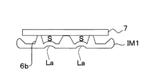
- FIG. 30 is a view of the cemented first lens array IM1 and the plate-like member 7 as viewed from the side.
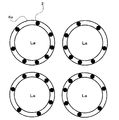
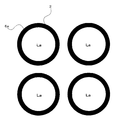
- the first lens array IM1 is provided with a protrusion 6.
- the protrusion 6 surrounds each of the plurality of lens portions La, and an adhesive region E is provided on the top 6a.
- the protrusion 6 is formed by integral molding with the first lens array IM1, for example, using a mold.
- the top portion 6a and the surface IM1a ′ are connected by an inclined surface 6b having a predetermined inclination angle. Therefore, when the first lens array IM1 and the plate-like member 7 are pressed in a state where the adhesive 2 is dropped on the top 6a of the first lens array IM1, gas is generated between the two adjacent adhesives 2. As shown in FIG. 29, the adhesive 2 dripped onto the top portion 6a does not spread in the radial direction of the top portion 6a, so that the circumferential direction of the top portion 6a can be referred to as a wetting pinning effect. It spreads along. Thus, as shown in FIG. 30, the top part 6a of the projection part 6 and the plate-shaped member 7 are joined.
- the protrusion 6 (the inclined surface 6b) forms a side wall of the sealing space S.
- the adhesive 2 may be dropped on a region on the opposing member to which the upper surface of the protruding portion 6 is bonded, or the adhesive 2 is applied to both. May be added dropwise.
- the lens portion is placed in the middle of pressing. Since the surrounding space is sealed and the adhesive 2 can be prevented from being pierced by the internal gas, and the direction in which the adhesive 2 spreads can be controlled by the protrusion 6, the lens portion after pressing with a small amount or number of drops Can be surrounded by an adhesive. That is, when there is no protrusion 6, the spreading direction of the adhesive by pressing cannot be controlled. Therefore, in order to realize an annular adhesive region like the protrusion 6, a large number of small-diameter point adhesives are arranged in an annular shape.
- the adhesive since the adhesive is guided by the protrusions 6 and spreads in an annular shape by providing the protrusions 6, the adhesive needs only a small number or amount of drops. Therefore, the time and process required for arranging the adhesive can be shortened. In addition, the adhesive 2 can be prevented from flowing into the sealed space due to the wet pinning effect. That is, the yield is improved.
- the inclination angle of the inclined surface 6b with respect to the top 6a is preferably close to 90 degrees. Further, the volume of the adhesive 2 dropped on the top 6a is equal to or less than the volume obtained from the area of the top 6a and the interval (the thickness of the adhesive layer) in the state where the first lens array IM1 and the plate-like member 7 are joined. It is desirable that
- the protrusion part 6 may be provided in the opposing member side.
- the protrusions 6 may be provided on both the first lens array IM1 and the opposing member as “first protrusions” and “second protrusions”. In this case, the top portion 6a of the first protrusion and the top portion 6a of the second protrusion are joined, so that the first protrusion (inclined surface 6b) and the second protrusion (inclined surface 6b) are sealed space S.
- the side wall is formed.
- ⁇ Modification 3> the structure of a monolithic glass molding lens made of a single material has been described as the lens array.
- a lens array made of a composite material in which a plurality of lens portions are formed on a substrate for example, It is also possible to use a wafer lens.
- the configuration of the lens units arranged in a two-dimensional matrix has been described, but the arrangement of the lens units is not limited to this.
- a staggered arrangement (a state in which the arrangement directions of a plurality of lens portions are obliquely crossed) may be used.
- the two-dimensionally arranged lens portions are arranged in up to two rows and arranged in a matrix of 2 ⁇ n (where n ⁇ 3), gas can be easily released.
- the adhesive around the central lens portion may be connected before the adhesive around the peripheral lens portion.
- the arrangement of the adhesive is taken into consideration so that the gas in the space around the central lens portion does not break through the adhesive even if the pressure advances after the adhesive around the central lens portion is connected. It is necessary to keep.
- the direction in which the gas in the space formed by the lens portions (or the lens portion and the opposing member) escapes can be controlled by changing the dropping position and the dropping amount of the adhesive 2. .
Landscapes
- Physics & Mathematics (AREA)
- General Physics & Mathematics (AREA)
- Optics & Photonics (AREA)
- Engineering & Computer Science (AREA)
- Health & Medical Sciences (AREA)
- Manufacturing & Machinery (AREA)
- Ophthalmology & Optometry (AREA)
- Mechanical Engineering (AREA)
- Lens Barrels (AREA)
Abstract
封止不良が少ないレンズユニットを得ることが可能なレンズユニットの製造方法を提供する。レンズユニットの製造方法は、滴下ステップと、封止空間形成ステップと、切断ステップとを有する。滴下ステップは、複数のレンズ部を有する第1レンズアレイ上の接着領域、及び対向部材上の接着領域の少なくとも一方に対し、接着剤を複数箇所に滴下する。封止空間形成ステップは、双方の接着領域を互いに対向させ、押圧することにより、第1レンズアレイ及び対向部材を接合し、複数のレンズ部毎に封止空間を形成する。更に、滴下ステップにおいて、第1の接着領域に対する接着剤の滴下条件と、それ以外の第2の接着領域に対する接着剤の滴下条件とを相違させ、封止空間形成ステップでは、押圧時に、第1の接着領域における複数の接着剤が、第2の接着領域における複数の接着剤よりも先に繋がる。
Description
本発明は、レンズユニットの製造方法、及びレンズアレイユニットの製造方法に関する。
光学レンズの製造分野において、ガラス基板に対して硬化性樹脂(熱硬化性樹脂や光硬化性樹脂等)からなるレンズ部を形成することにより、耐熱性の向上を図る技術が存在する。この技術を適用したレンズユニットの製造方法としては、たとえば特許文献1に記載された方法がある。
特許文献1に記載された撮像レンズ(レンズユニット)の製造方法は、まず、ガラス基板10の両面に対して樹脂製のレンズ部13、14を複数設けたウエハレンズ1及び3を作製する。次に、スペーサー2を介してウエハレンズ1及び3を積層する。ウエハレンズ1及び3とスペーサー2は接着部に滴下された接着剤により固着されることでレンズアレイユニットが得られ、また、それにより、ウエハレンズ1及び3とスペーサー2により密閉された封止空間が形成される(特許文献1の図1(b)参照)。その後、レンズ部毎に個片化して複数の撮像レンズ(レンズユニット)を得る。このとき、レンズユニットの性能に影響を与える可能性があるため、封止空間には異物(埃、水等)が侵入しないようにする必要がある。
ガラスモールレンズアレイ同士を直接的に接合する場合や、特許文献1のようにウエハレンズアレイ同士をスペーサーを介して接合する場合、レンズアレイやスペーサーに対して各レンズ部をそれぞれ囲むように環状に接着剤を塗布してからこれらを積層すると、各レンズ間に形成される空間が接着剤によって密閉され、レンズアレイ同士を接合するために圧力を加えると、密閉空間内の圧力が上昇し、密閉空間内の気体が接着剤を突き破ってしまう恐れがある。そこで、接着剤を滴下することで複数間隔をあけて点状に配置することが考えられる。このようにすると、レンズアレイ同士を接合させるために圧力を加えたときに、各レンズ間に形成される空間内の気体が接着剤の隙間から逃げるので、接着剤を突き破ることを回避し得るものと期待される。しかしながら、実際には以下のような課題が存在することが判明した。
図31Aから図31Cは、接着剤を滴下して点状に配置した例を示しており、レンズアレイ(図31Cはレンズユニット)をレンズの光軸方向から見た図である。また、図31B及び図31Cは、一方のレンズアレイに対して他方のレンズアレイを押圧している状態を示しているが、図では他方のレンズアレイは図示を省略している。各レンズアレイには凹レンズ部Lが設けられており、それぞれの凹レンズ部Lが対向することにより空間(接合された後は封止空間)が形成される。
レンズアレイ同士を押圧する際、図31Aに示すように、各レンズ部間に形成される空間内の気体が空間外に逃げようとする(図31Aの矢印参照)。レンズ部Lが近接している場合、空間から逃げた気体の一部(図31Aの破線矢印)によって、レンズ部Lが隣接する接着領域にある接着剤2は、各レンズ部L囲む方向に繋がるのを妨げられ、逆に、隣接するレンズ部Lの周りにある接着剤と繋がることで他の空間と連結され、封止不良を引き起こす場合がある(図31B参照)。
このような状態でレンズ部L毎に切断すると(図31C参照)、封止されていない部分αから切削液や水等が空間内に侵入し、レンズユニットの性能に影響を与えるという問題が生じる。封止されていない部分はレンズ部や接着剤2で囲まれているため、切断前に接着剤2を追加で塗布することもできない。
従って本発明は、上記課題を解決するために、封止不良が少ないレンズユニット及びレンズアレイユニットを得ることが可能なレンズユニットの製造方法、及びレンズアレイユニットの製造方法を提供することを目的とする。
上記課題を解決するために、請求項1記載のレンズユニットの製造方法は、滴下ステップと、封止空間形成ステップと、切断ステップとを有する。滴下ステップは、2次元的に配列された複数のレンズ部を有する第1レンズアレイ上の接着領域、及び第1レンズアレイに対向して設けられる対向部材上の接着領域の少なくとも一方に対し、接着剤を複数箇所に滴下する。封止空間形成ステップは、双方の接着領域を互いに対向させ、第1レンズアレイ及び対向部材の少なくとも一方を他方に対して押圧することにより、第1レンズアレイ及び対向部材を接合し、複数のレンズ部毎に封止空間を形成する。切断ステップは、接合された第1レンズアレイ及び対向部材を封止空間単位で切断する。更に、滴下ステップにおいて、接着領域のうち、複数のレンズ部間に相当する位置に設定された第1の接着領域に対する接着剤の滴下条件と、それ以外の第2の接着領域に対する接着剤の滴下条件とを相違させ、封止空間形成ステップでは、押圧時に、第1の接着領域における複数の接着剤が、第2の接着領域における複数の接着剤よりも先に繋がる。
また、上記課題を解決するために、請求項2記載のレンズユニットの製造方法は、請求項1記載のレンズユニットの製造方法であって、第1レンズアレイには、複数のレンズ部それぞれを取り囲み、且つその頂部に接着領域を有する突起部が設けられる。そして、封止空間形成ステップにおいて、突起部の頂部と対向部材とが接合されることにより、突起部は封止空間の側壁を形成する。
また、上記課題を解決するために、請求項3記載のレンズユニットの製造方法は、請求項1記載のレンズユニットの製造方法であって、対向部材には、第1レンズアレイと接合されたときに、複数のレンズ部それぞれを取り囲み、且つその頂部に接着領域を有する突起部が設けられる。そして、封止空間形成ステップにおいて、第1レンズアレイと突起部の頂部とが接合されることにより、突起部は封止空間の側壁を形成する。
また、上記課題を解決するために、請求項4記載のレンズユニットの製造方法は、請求項1記載のレンズユニットの製造方法であって、第1レンズアレイには、複数のレンズ部それぞれを取り囲み、且つその頂部に接着領域を有する第1突起部が設けられ、対向部材には、第1レンズアレイと接合されたときに、複数のレンズ部それぞれを取り囲み、且つその頂部に接着領域を有する第2突起部が設けられる。そして、封止空間形成ステップにおいて、第1突起部の頂部と2突起部の頂部とが接合されることにより、第1突起部及び第2突起部は封止空間の側壁を形成する。
また、上記課題を解決するために、請求項5記載のレンズユニットの製造方法は、滴下ステップと、封止空間形成ステップと、切断ステップとを有する。滴下ステップは、2次元的に配列された複数のレンズ部を有する第1レンズアレイ上の接着領域と、第1レンズアレイに対向して設けられる対向部材上の接着領域と、第1レンズアレイと対向部材との間に配置され、第1レンズアレイと接合されたときに、複数のレンズ部それぞれが収容される複数の孔部を有するスペーサー基板の両面に設けられた接着領域と、について、第1レンズアレイの接着領域及びスペーサー基板の一面側の接着領域の少なくとも一つと、対向部材の接着領域及びスペーサー基板の他面側の接着領域の少なくとも一つとのそれぞれに対し、接着剤を複数箇所に滴下する。封止空間形成ステップは、第1レンズアレイの接着領域及びスペーサー基板の一面側の接着領域を互いに対向させ、第1レンズアレイ及びスペーサー基板の少なくとも一方を他方に対して押圧し、且つ対向部材の接着領域及びスペーサー基板の他面側の接着領域を互いに対向させ、対向部材及びスペーサー基板の少なくとも一方を他方に対して押圧することにより、第1レンズアレイ、対向部材及びスペーサー基板を接合し、複数のレンズ部毎に封止空間を形成する。切断ステップは、接合された第1レンズアレイ、対向部材及びスペーサー基板を封止空間単位で切断する。更に、滴下ステップにおいて、接着領域のうち、複数のレンズ部間に相当する位置の第1の接着領域に対する接着剤の滴下条件と、それ以外の第2の接着領域に対する接着剤の滴下条件とを相違させ、封止空間形成ステップでは、押圧時に、第1の接着領域における複数の接着剤が、第2の接着領域における複数の接着剤よりも先に繋がる。
また、上記課題を解決するために、請求項6記載のレンズユニットの製造方法は、請求項1又は5に記載のレンズユニットの製造方法であって、滴下ステップにおいて、第1の接着領域における接着剤の間隔を、第2の接着領域における接着剤の間隔より小さくする。また、請求項6に記載の発明を請求項2~4のいずれか一項に記載の発明に適用することも可能である。
また、上記課題を解決するために、請求項7記載のレンズユニットの製造方法は、請求項1又は5に記載のレンズユニットの製造方法であって、滴下条件は、接着剤の滴下位置の間隔を含む。そして、第1の接着領域に滴下される接着剤の滴下位置の間隔と、第2の接着領域に滴下される接着剤の滴下位置の間隔とを変更する。また、請求項7に記載の発明を請求項2~4及び6のいずれか一項に記載の発明に適用することも可能である。
また、上記課題を解決するために、請求項8記載のレンズユニットの製造方法は、請求項1又は5に記載のレンズユニットの製造方法であって、第1の接着領域は、少なくとも3つのレンズ部によって囲まれる領域、及び2つの隣り合うレンズ部間の領域を含む。そして、少なくとも3つのレンズ部によって囲まれる領域における接着剤の間隔が、2つの隣り合うレンズ部間の領域における接着剤の間隔よりも小さい。また、請求項8に記載の発明を請求項2~4、6及び7のいずれか一項に記載の発明に適用することも可能である。
また、上記課題を解決するために、請求項9記載のレンズユニットの製造方法は、請求項1又は5に記載のレンズユニットの製造方法であって、滴下条件は、接着剤の滴下量を含む。そして、第1の接着領域に滴下される接着剤の滴下量と、第2の接着領域に滴下される接着剤の滴下量とを変更する。また、請求項9に記載の発明を請求項2~4及び6~8のいずれか一項に記載の発明に適用することも可能である。
また、上記課題を解決するために、請求項10記載のレンズユニットの製造方法は、請求項1又は5に記載のレンズユニットの製造方法であって、対向部材は、板状部材である。また、請求項10に記載の発明を請求項2~4及び6~9のいずれか一項に記載の発明に適用することも可能である。
また、上記課題を解決するために、請求項11記載のレンズユニットの製造方法は、請求項1又は5に記載のレンズユニットの製造方法であって、対向部材は、2次元的に配列された複数のレンズ部を有する第2レンズアレイである。また、請求項11に記載の発明を請求項2~4及び6~10のいずれか一項に記載の発明に適用することも可能である。
また、上記課題を解決するために、請求項12記載のレンズアレイユニットの製造方法は、滴下ステップと、封止空間形成ステップとを有する。滴下ステップは、2次元的に配列された複数のレンズ部を有する第1レンズアレイ上の接着領域、及び第1レンズアレイに対向して設けられる対向部材上の接着領域の少なくとも一方に対し、接着剤を複数箇所に滴下する。封止空間形成ステップは、双方の接着領域を互いに対向させ、第1レンズアレイ及び対向部材の少なくとも一方を他方に対して押圧することにより、第1レンズアレイ及び対向部材を接合し、複数のレンズ部毎に封止空間を形成する。更に、滴下ステップにおいて、接着領域のうち、複数のレンズ部間に相当する位置に設定された第1の接着領域に対する接着剤の滴下条件と、それ以外の第2の接着領域に対する接着剤の滴下条件とを相違させ、封止空間形成ステップでは、押圧時に、第1の接着領域における複数の接着剤が、第2の接着領域における複数の接着剤よりも先に繋がる。
また、上記課題を解決するために、請求項13記載のレンズアレイユニットの製造方法は、滴下ステップと、封止空間形成ステップとを有する。滴下ステップは、2次元的に配列された複数のレンズ部を有する第1レンズアレイ上の接着領域と、第1レンズアレイに対向して設けられる対向部材上の接着領域と、第1レンズアレイと対向部材との間に配置され、第1レンズアレイと接合されたときに、複数のレンズ部それぞれが収容される複数の孔部を有するスペーサー基板の両面に設けられた接着領域と、について、第1レンズアレイの接着領域及びスペーサー基板の一面側の接着領域の少なくとも一つと、対向部材の接着領域及びスペーサー基板の他面側の接着領域の少なくとも一つとのそれぞれに対し、接着剤を複数箇所に滴下する。封止空間形成ステップは、第1レンズアレイの接着領域及びスペーサー基板の一面側の接着領域を互いに対向させ、第1レンズアレイ及びスペーサー基板の少なくとも一方を他方に対して押圧し、且つ対向部材の接着領域及びスペーサー基板の他面側の接着領域を互いに対向させ、対向部材及びスペーサー基板の少なくとも一方を他方に対して押圧することにより、第1レンズアレイ、対向部材及びスペーサー基板を接合し、複数のレンズ部毎に封止空間を形成する。更に、滴下ステップにおいて、接着領域のうち、複数のレンズ部間に相当する位置の第1の接着領域に対する接着剤の滴下条件と、それ以外の第2の接着領域に対する接着剤の滴下条件とを相違させ、封止空間ステップでは、押圧時に、第1の接着領域における複数の接着剤が、第2の接着領域における複数の接着剤よりも先に繋がる。
また、上記課題を解決するために、請求項14記載のレンズアレイユニットの製造方法は、請求項12又は13記載のレンズアレイユニットの製造方法であって、滴下ステップにおいて、第1の接着領域における接着剤の間隔を、第2の接着領域における接着剤の間隔より小さくする。
また、上記課題を解決するために、請求項2記載のレンズユニットの製造方法は、請求項1記載のレンズユニットの製造方法であって、第1レンズアレイには、複数のレンズ部それぞれを取り囲み、且つその頂部に接着領域を有する突起部が設けられる。そして、封止空間形成ステップにおいて、突起部の頂部と対向部材とが接合されることにより、突起部は封止空間の側壁を形成する。
また、上記課題を解決するために、請求項3記載のレンズユニットの製造方法は、請求項1記載のレンズユニットの製造方法であって、対向部材には、第1レンズアレイと接合されたときに、複数のレンズ部それぞれを取り囲み、且つその頂部に接着領域を有する突起部が設けられる。そして、封止空間形成ステップにおいて、第1レンズアレイと突起部の頂部とが接合されることにより、突起部は封止空間の側壁を形成する。
また、上記課題を解決するために、請求項4記載のレンズユニットの製造方法は、請求項1記載のレンズユニットの製造方法であって、第1レンズアレイには、複数のレンズ部それぞれを取り囲み、且つその頂部に接着領域を有する第1突起部が設けられ、対向部材には、第1レンズアレイと接合されたときに、複数のレンズ部それぞれを取り囲み、且つその頂部に接着領域を有する第2突起部が設けられる。そして、封止空間形成ステップにおいて、第1突起部の頂部と2突起部の頂部とが接合されることにより、第1突起部及び第2突起部は封止空間の側壁を形成する。
また、上記課題を解決するために、請求項5記載のレンズユニットの製造方法は、滴下ステップと、封止空間形成ステップと、切断ステップとを有する。滴下ステップは、2次元的に配列された複数のレンズ部を有する第1レンズアレイ上の接着領域と、第1レンズアレイに対向して設けられる対向部材上の接着領域と、第1レンズアレイと対向部材との間に配置され、第1レンズアレイと接合されたときに、複数のレンズ部それぞれが収容される複数の孔部を有するスペーサー基板の両面に設けられた接着領域と、について、第1レンズアレイの接着領域及びスペーサー基板の一面側の接着領域の少なくとも一つと、対向部材の接着領域及びスペーサー基板の他面側の接着領域の少なくとも一つとのそれぞれに対し、接着剤を複数箇所に滴下する。封止空間形成ステップは、第1レンズアレイの接着領域及びスペーサー基板の一面側の接着領域を互いに対向させ、第1レンズアレイ及びスペーサー基板の少なくとも一方を他方に対して押圧し、且つ対向部材の接着領域及びスペーサー基板の他面側の接着領域を互いに対向させ、対向部材及びスペーサー基板の少なくとも一方を他方に対して押圧することにより、第1レンズアレイ、対向部材及びスペーサー基板を接合し、複数のレンズ部毎に封止空間を形成する。切断ステップは、接合された第1レンズアレイ、対向部材及びスペーサー基板を封止空間単位で切断する。更に、滴下ステップにおいて、接着領域のうち、複数のレンズ部間に相当する位置の第1の接着領域に対する接着剤の滴下条件と、それ以外の第2の接着領域に対する接着剤の滴下条件とを相違させ、封止空間形成ステップでは、押圧時に、第1の接着領域における複数の接着剤が、第2の接着領域における複数の接着剤よりも先に繋がる。
また、上記課題を解決するために、請求項6記載のレンズユニットの製造方法は、請求項1又は5に記載のレンズユニットの製造方法であって、滴下ステップにおいて、第1の接着領域における接着剤の間隔を、第2の接着領域における接着剤の間隔より小さくする。また、請求項6に記載の発明を請求項2~4のいずれか一項に記載の発明に適用することも可能である。
また、上記課題を解決するために、請求項7記載のレンズユニットの製造方法は、請求項1又は5に記載のレンズユニットの製造方法であって、滴下条件は、接着剤の滴下位置の間隔を含む。そして、第1の接着領域に滴下される接着剤の滴下位置の間隔と、第2の接着領域に滴下される接着剤の滴下位置の間隔とを変更する。また、請求項7に記載の発明を請求項2~4及び6のいずれか一項に記載の発明に適用することも可能である。
また、上記課題を解決するために、請求項8記載のレンズユニットの製造方法は、請求項1又は5に記載のレンズユニットの製造方法であって、第1の接着領域は、少なくとも3つのレンズ部によって囲まれる領域、及び2つの隣り合うレンズ部間の領域を含む。そして、少なくとも3つのレンズ部によって囲まれる領域における接着剤の間隔が、2つの隣り合うレンズ部間の領域における接着剤の間隔よりも小さい。また、請求項8に記載の発明を請求項2~4、6及び7のいずれか一項に記載の発明に適用することも可能である。
また、上記課題を解決するために、請求項9記載のレンズユニットの製造方法は、請求項1又は5に記載のレンズユニットの製造方法であって、滴下条件は、接着剤の滴下量を含む。そして、第1の接着領域に滴下される接着剤の滴下量と、第2の接着領域に滴下される接着剤の滴下量とを変更する。また、請求項9に記載の発明を請求項2~4及び6~8のいずれか一項に記載の発明に適用することも可能である。
また、上記課題を解決するために、請求項10記載のレンズユニットの製造方法は、請求項1又は5に記載のレンズユニットの製造方法であって、対向部材は、板状部材である。また、請求項10に記載の発明を請求項2~4及び6~9のいずれか一項に記載の発明に適用することも可能である。
また、上記課題を解決するために、請求項11記載のレンズユニットの製造方法は、請求項1又は5に記載のレンズユニットの製造方法であって、対向部材は、2次元的に配列された複数のレンズ部を有する第2レンズアレイである。また、請求項11に記載の発明を請求項2~4及び6~10のいずれか一項に記載の発明に適用することも可能である。
また、上記課題を解決するために、請求項12記載のレンズアレイユニットの製造方法は、滴下ステップと、封止空間形成ステップとを有する。滴下ステップは、2次元的に配列された複数のレンズ部を有する第1レンズアレイ上の接着領域、及び第1レンズアレイに対向して設けられる対向部材上の接着領域の少なくとも一方に対し、接着剤を複数箇所に滴下する。封止空間形成ステップは、双方の接着領域を互いに対向させ、第1レンズアレイ及び対向部材の少なくとも一方を他方に対して押圧することにより、第1レンズアレイ及び対向部材を接合し、複数のレンズ部毎に封止空間を形成する。更に、滴下ステップにおいて、接着領域のうち、複数のレンズ部間に相当する位置に設定された第1の接着領域に対する接着剤の滴下条件と、それ以外の第2の接着領域に対する接着剤の滴下条件とを相違させ、封止空間形成ステップでは、押圧時に、第1の接着領域における複数の接着剤が、第2の接着領域における複数の接着剤よりも先に繋がる。
また、上記課題を解決するために、請求項13記載のレンズアレイユニットの製造方法は、滴下ステップと、封止空間形成ステップとを有する。滴下ステップは、2次元的に配列された複数のレンズ部を有する第1レンズアレイ上の接着領域と、第1レンズアレイに対向して設けられる対向部材上の接着領域と、第1レンズアレイと対向部材との間に配置され、第1レンズアレイと接合されたときに、複数のレンズ部それぞれが収容される複数の孔部を有するスペーサー基板の両面に設けられた接着領域と、について、第1レンズアレイの接着領域及びスペーサー基板の一面側の接着領域の少なくとも一つと、対向部材の接着領域及びスペーサー基板の他面側の接着領域の少なくとも一つとのそれぞれに対し、接着剤を複数箇所に滴下する。封止空間形成ステップは、第1レンズアレイの接着領域及びスペーサー基板の一面側の接着領域を互いに対向させ、第1レンズアレイ及びスペーサー基板の少なくとも一方を他方に対して押圧し、且つ対向部材の接着領域及びスペーサー基板の他面側の接着領域を互いに対向させ、対向部材及びスペーサー基板の少なくとも一方を他方に対して押圧することにより、第1レンズアレイ、対向部材及びスペーサー基板を接合し、複数のレンズ部毎に封止空間を形成する。更に、滴下ステップにおいて、接着領域のうち、複数のレンズ部間に相当する位置の第1の接着領域に対する接着剤の滴下条件と、それ以外の第2の接着領域に対する接着剤の滴下条件とを相違させ、封止空間ステップでは、押圧時に、第1の接着領域における複数の接着剤が、第2の接着領域における複数の接着剤よりも先に繋がる。
また、上記課題を解決するために、請求項14記載のレンズアレイユニットの製造方法は、請求項12又は13記載のレンズアレイユニットの製造方法であって、滴下ステップにおいて、第1の接着領域における接着剤の間隔を、第2の接着領域における接着剤の間隔より小さくする。
本発明によれば、滴下ステップにおいて、複数のレンズ部間に相当する位置に設定された第1の接着領域に対する接着剤の滴下条件と、それ以外の第2の接着領域に対する接着剤の滴下条件とを相違させる。そして、封止空間ステップにおいて、レンズアレイと対向部材との押圧時に、第1の接着領域における複数の接着剤が、第2の接着領域における複数の接着剤よりも先に繋がる。このため、複数のレンズ部間に滴下された接着剤が、レンズ部毎に形成される空間から外部に逃げる気体で押され、当該空間同士が連結することを防止できる。従って、封止不良が少ないレンズユニットを製造することが可能となる。
<第1実施形態>
図1から図14を参照して、本実施形態に係るレンズユニット1の製造方法について説明する。本実施形態では、図4に示すように、第1レンズアレイIM1として、2次元マトリクス状に配列された4つのレンズ部Laを有する構成を用いる(図4は第1レンズアレイIM1を側面から見た図であるため、2つのレンズ部Laのみ記載)。また、第1レンズアレイIM1に対向して設けられる対向部材として、図6に示すように、2次元マトリクス状に配列された4つのレンズ部Lbを有する構成(第2レンズアレイIM2。図6は第2レンズアレイIM2を側面から見た図であるため、2つのレンズ部Lbのみ記載)を用いる。
図1から図14を参照して、本実施形態に係るレンズユニット1の製造方法について説明する。本実施形態では、図4に示すように、第1レンズアレイIM1として、2次元マトリクス状に配列された4つのレンズ部Laを有する構成を用いる(図4は第1レンズアレイIM1を側面から見た図であるため、2つのレンズ部Laのみ記載)。また、第1レンズアレイIM1に対向して設けられる対向部材として、図6に示すように、2次元マトリクス状に配列された4つのレンズ部Lbを有する構成(第2レンズアレイIM2。図6は第2レンズアレイIM2を側面から見た図であるため、2つのレンズ部Lbのみ記載)を用いる。
<レンズアレイの成形工程>
まず、図1から図4を参照して、レンズアレイの成形工程について説明を行う。図1は、本実施形態に係るレンズアレイの成形工程を示すフローチャートである。本実施形態では、1回の成形工程で4つのレンズ部Laを有する第1レンズアレイIM1を作製することができる金型(上金型12、下金型22)を用いる。図2~4では、金型及び第1レンズアレイIM1を側面から見た構成について説明を行う。
まず、図1から図4を参照して、レンズアレイの成形工程について説明を行う。図1は、本実施形態に係るレンズアレイの成形工程を示すフローチャートである。本実施形態では、1回の成形工程で4つのレンズ部Laを有する第1レンズアレイIM1を作製することができる金型(上金型12、下金型22)を用いる。図2~4では、金型及び第1レンズアレイIM1を側面から見た構成について説明を行う。
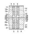
図2に示すように、上金型12は、底板4、スペーサー5、コア支持部材11及びコア13を含んで構成されている。
底板4は上金型12の上底を覆う板状部材である。スペーサー5はコア13の突き出し量を調整する。コア支持部材11は、上金型12内に設けられ、コア13を支持する。コア13は、転写面13a(本実施形態では、凸形状)を有し、ガラスGLに対して押圧されることにより、その形状を転写する。本実施形態において、コア支持部材11及びコア13は、それぞれ4つ設けられている。コア13は、上金型12の下面12bにマトリクス状に配置されている。
図2に示すように、下金型22は、底板4、スペーサー5、コア支持部材21及びコア23を含んで構成されている。
底板4は下金型22の下底を覆う板状部材である。スペーサー5はコア23の突き出し量を調整する。コア支持部材21は、下金型22内に設けられ、コア23を支持する。コア23は、転写面23a(本実施形態では、凹形状)を有し、ガラスGLに対して押圧されることにより、その形状を転写する。本実施形態において、コア支持部材21及びコア23は、それぞれ4つ設けられている。コア23は、下金型22の上面22bにマトリクス状に配置されている。
第1レンズアレイIM1の成形は、まず、図2に示すように、溶融させたガラスGLを貯蔵する貯蔵部(不図示)に連通する白金ノズルNZの下方に下金型22を位置させる。そして、白金ノズルNZから溶融したガラスGLの液滴を、下金型22の上面22b上に一括滴下させる(S10)。かかる状態では、ガラスGLの粘度は低いので、落下したガラスGLは、上面22b上に広がり、コア23の転写面23a内に容易に進入する。それにより、ガラスGLに転写面23aの形状が転写される(S11)。
次いで、S10でガラスGLが滴下された下金型22を、ガラスGLが冷却する前に、上金型12の下方位置まで移動させて上金型12と下金型22とを対向させる。そして、位置決めガイド(不図示)を用いて上金型12と下金型22との位置合わせを行う(S12)。
更に、図3に示すように、上金型12と下金型22とを接近させて、ガラスGLの成形を行う。これにより、コア13の転写面13aの形状がガラスGLに転写される(S13)。このとき、上金型12の下面12bと下金型22の上面22bとが、所定の距離で離間するように保持してガラスGLを冷却させる。ガラスGLは、周囲に回り込んでテーパ部22gを覆った状態で固化する。
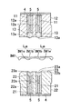
その後、図4に示すように、上金型12と下金型22とを離間させ、ガラスGLを取り出すことで、第1レンズアレイIM1が成形される(S14)。同様の手法により、第2レンズアレイIM2を成形する。
図4に示すように、第1レンズアレイIM1は、上金型12の転写面13aにより転写成形された凹状光学面IM1bと、下金型22の転写面23aにより転写形成された凸状光学面IM1eとを有する。凹状光学面IM1b及び凸状光学面IM1eがレンズ部Laを構成する。
同様に、第2レンズアレイIM2は、上金型12の転写面13aにより転写成形された凹状光学面IM2bと、下金型22の転写面23aにより転写形成された凸状光学面IM2eとを有する。凹状光学面IM2b及び凸状光学面IM2eがレンズ部Lbを構成する(図6参照)。
なお、本実施形態において、第1レンズアレイIM1、第2レンズアレイIM2は同じ形状であるが、異なる形状であってもよい。
<レンズユニットの製造工程>
次に、図5から図9を参照して、レンズユニット1の製造工程について説明を行う。図5は、本実施形態に係るレンズユニット1の製造工程を示すフローチャートである。
次に、図5から図9を参照して、レンズユニット1の製造工程について説明を行う。図5は、本実施形態に係るレンズユニット1の製造工程を示すフローチャートである。
図6に示すように、成形された第1レンズアレイIM1を治具JZで保持し、第1レンズアレイIM1の表面IM1aに接着剤2を滴下する(S20)。接着剤2は、滴下装置(不図示)等により表面IM1aの複数箇所に滴下される。なお、接着剤の滴下に当たっては、滴下装置(不図示)のノズルを滴下対象物である第1レンズアレイIM1の表面IM1aに近づけてノズルと表面IM1aとの双方に接着剤が接するようにノズルから接着剤を吐出することが好ましいが、これに限るものではなく、接着剤が表面IM1aに達したときには接着剤がノズルから離れるように接着剤を吐出してもよい。接着剤2の滴下方法の詳細については後述する。S20が本実施形態における「滴下ステップ」の一例である。表面IM1a及び表面IM2aが本実施形態における「接着領域」の一例である。その後、治具JZで成形された第2レンズアレイIM2を保持し、第1レンズアレイIM1の表面IM1aと、第2レンズアレイIM2の表面IM2aとを対向させ、両者間にドーナツ板状の遮光部材SHを配置する(図6参照)。
接着剤2としては、たとえば、エン-チオール系樹脂、エポキシ系樹脂、アクリル系樹脂などからなる、光硬化性接着剤や熱硬化性接着剤が用いられ、好ましくは、滴下環境下での粘度が100~2000mPa・sのものを用いる。粘度が100mPa・sを下回ると滴下後に接着剤同士がすぐに繋がってしまい、後述するような押圧時の接着剤の広がりをうまく制御できなくなったり、接着剤を十分押し広げられなくなったりする恐れがある。粘度が2000mPa・sを上回ると、ノズルからの接着剤の吐出が難しくなり、小径のレンズユニットの製造に適さなくなる恐れがある。本実施形態では、滴下を室温環境下で行い、接着剤2として、UV(Ultra Violet)硬化特性を有するポリエン-ポリチオール系接着剤(室温における粘度300mPa・s)を用いる。
次に、図7に示すように、第1レンズアレイIM1及び第2レンズアレイIM2の少なくとも一方を他方に対して押圧することにより、表面IM1a、IM2aを介して、第1レンズアレイIM1と第2レンズアレイIM2とを接合する(S21)。押圧後、UV照明(不図示)等により紫外線を照射し、接着剤を硬化させることで第1レンズアレイIM1と第2レンズアレイIM2とが接合される。このようにして、レンズアレイユニットIM3が得られる。
S21の状態において、第1レンズアレイIM1に成形された凹状光学面IM1bと、第2レンズアレイIM2に成形された凹状光学面IM2bとが封止空間を形成する。S21は、本実施形態における「封止空間形成ステップ」の一例である。本実施形態において、「封止空間」とは、第1レンズアレイIM1と、対向部材(第2レンズアレイIM2)と、接着剤とで密閉された空間(凹状光学面IM1bと凹状光学面IM2bとを内壁面として外部から隔離された空間)である。
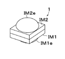
その後、図8に示すように、レンズアレイユニットIM3を治具JZから取り外し、ダイシングブレードDBにより、レンズアレイユニットIM3を封止空間単位で切断する(S22)。「封止空間単位で切断」とは、それぞれの封止空間を保持した状態で、個々の封止空間毎に分離させることをいう。その結果、図9に示すようなレンズユニット1が完成する(S23。図9では1つのレンズユニット1のみ図示している)。本実施形態では、レンズアレイユニットIM3から4つのレンズユニット1を得ることができる。S22は、本実施形態における「切断ステップ」の一例である。
<接着剤の滴下方法>
次に図10から図14を参照して、本実施形態に係る接着剤2の滴下方法について説明する。本実施形態では、第1レンズアレイIM1の表面IM1aに接着剤2を滴下する場合について述べる。図10から図14は、第1レンズアレイIM1を凹状光学面IM1b側から見た図面である。また、図12から図14は、第1レンズアレイIM1の凹状光学面IM1bと、第2レンズアレイIM2の凹状光学面IM2bとを押圧している状態を示しているが、図では第2レンズアレイIM2の記載を省略している。
次に図10から図14を参照して、本実施形態に係る接着剤2の滴下方法について説明する。本実施形態では、第1レンズアレイIM1の表面IM1aに接着剤2を滴下する場合について述べる。図10から図14は、第1レンズアレイIM1を凹状光学面IM1b側から見た図面である。また、図12から図14は、第1レンズアレイIM1の凹状光学面IM1bと、第2レンズアレイIM2の凹状光学面IM2bとを押圧している状態を示しているが、図では第2レンズアレイIM2の記載を省略している。
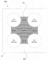
図10に示すように、本実施形態では、4つのレンズ部La(凹状光学面IM1b)の周囲に接着領域Eが予め設定されている。また、接着領域Eは、複数のレンズ部Laの間に設定される接着領域E1(第1の接着領域E1)と、それ以外の接着領域E2(第2の接着領域E2)を含んでいる。接着領域E1は、隣接するレンズ部La双方に接する接線のうち、外側の接線によって形成される多角形内に設定される領域である。更に、接着領域E1は、少なくとも3つのレンズ部Laによって囲まれる領域(本実施形態では、4つのレンズ部Laで囲まれる領域)E11、及び隣接する2つのレンズ部Laによって挟まれる領域(本実施形態では4つの領域)E12を含んでいる。領域E12は、隣接するレンズ部La双方に接する接線によって囲まれる範囲であって、領域E11を除く任意の領域である。
本実施形態では、S20の滴下ステップにおいて、複数のレンズ部La間に相当する位置の第1の接着領域E1に対する接着剤2の滴下条件と、それ以外の第2の接着領域E2に対する接着剤2の滴下条件とを相違させる。本実施形態では、滴下条件として接着剤2の滴下位置の間隔を異ならせる例について説明する。「滴下位置」とは、滴下装置(不図示)のノズル先端の鉛直下方位置をいう。
具体的には、図11に示すように、第1の接着領域E1における接着剤2の滴下位置の間隔(p11、p12)が、第2の接着領域E2における接着剤2の滴下位置の間隔(p2)よりも狭くなるようにする。更に、本実施形態では、図11に示すように、領域E11における接着剤2の滴下位置の間隔p11が、領域E12における接着剤2の滴下位置の間隔p12よりも小さくなるようにする。
このために、滴下装置(不図示)は、第1レンズアレイIM1に対する移動ピッチを変更させつつ、第1レンズアレイIM1に対して相対的に移動し、接着剤2を複数箇所に滴下する。
なお、本実施形態において、各接着剤2の滴下量(径のサイズ)はほぼ均一であるものとする。このため、領域E11における各接着剤2の間隔e11、e12が、領域E12における各接着剤2の間隔e2よりも小さくなる。
このように接着剤2が滴下された後、第1レンズアレイIM1及び第2レンズアレイIM2のいずれか一方に対して他方を押圧すると、接着剤2が表面IM1a上に広がっていく。そして、図12に示すように、接着剤2が密に配置された領域E11から順に隣接する接着剤2同士が連結される。
更に、押圧を進めると、図13に示すように、E12の領域に配置された接着剤2が凹状光学面IM1bの周に沿って連結しながら広がっていく。このように接着剤2が広がっていくことによって、凹状光学面IM1b及び凹状光学面IM2bで形成される空間内の気体は接着剤2が連結されていない部分(図13の矢印方向)から外部に逃げていく。この時点で、領域E11の接着剤2同士は既に連結しており、接着剤2が連結された部分が気体によって押しのけられて隣接するレンズ部周囲の空間を連通させるようなことが起きない。よって、凹状光学面IM1b及び凹状光学面IM2bによって形成される空間同士が連結することなく、各レンズ部Laそれぞれが密閉される封止空間Sが形成される(図14参照)。
本実施形態では、第1レンズアレイIM1の表面IM1aのみに接着剤が滴下される構成について説明を行ったが、接着剤が滴下される対象はこれに限られない。たとえば、第2レンズアレイIM2の表面IM2aのみに接着剤が滴下される構成であってもよい。或いは、表面IM1a及び表面IM2aの双方に接着剤が滴下される構成であってもよい。表面IM1a及び表面IM2aの双方に接着剤を滴下する場合は、双方に滴下される接着剤がレンズの光軸方向から見て上記関係を満たすように滴下すればよい。
本実施形態では、対向部材として第2レンズアレイIM2を用いて説明を行ったがこれに限られない。たとえば、レンズ部が形成されていない板状部材を対向部材として用いることが可能である。この場合、第1レンズアレイIM1の凹状光学面IM1bと板状部材とにより、封止空間が形成される。また、この場合には、板状部材側に接着剤2を滴下してもよい。その際、第1の接着領域E1は、複数のレンズ部La間に相当する位置(第1レンズアレイIM1と対向部材との接合時において、複数のレンズ部La間と対向する板状部材上の位置)に設けられる。
<作用・効果>
本実施形態の作用及び効果について説明する。
本実施形態の作用及び効果について説明する。
本実施形態に係るレンズユニットの製造方法は、滴下ステップと、封止空間形成ステップと、切断ステップと、を有する。滴下ステップは、2次元的に配列された複数のレンズ部Laを有する第1レンズアレイIM1上の接着領域E(E1、E2)に対し、接着剤2を複数箇所に滴下する。封止空間形成ステップは、接着領域Eと第1レンズアレイIM1に対向して設けられる第2レンズアレイIM2上の接着領域とを互いに対向させ、第1レンズアレイIM1及び第2レンズアレイIM2の少なくとも一方を他方に対して押圧することにより、第1レンズアレイIM1及び第2レンズアレイIM2を接合し、複数のレンズ部La毎に封止空間を形成する。切断ステップは、接合された第1レンズアレイIM1及び第2レンズアレイIM2を封止空間単位で切断する。更に、滴下ステップにおいて、接着領域のうち、複数のレンズ部La間に相当する位置に設定された第1の接着領域E1に対する接着剤2の滴下条件と、それ以外の第2の接着領域E2に対する接着剤2の滴下条件とを相違させ、封止空間形成ステップでは、押圧時に、第1の接着領域E1における複数の接着剤2が、第2の接着領域E2における複数の接着剤2よりも先に繋がる。
また、本実施形態に係るレンズアレイユニットの製造方法は、滴下ステップと、封止空間形成ステップとを有する。滴下ステップは、2次元的に配列された複数のレンズ部Laを有する第1レンズアレイIM1上の接着領域E(E1、E2)、及び第1レンズアレイIM1に対向して設けられる第2レンズアレイIM2上の接着領域Eの少なくとも一方に対し、接着剤2を複数箇所に滴下する。封止空間形成ステップは、双方の接着領域Eを互いに対向させ、第1レンズアレイIM1及び第2レンズアレイIM2の少なくとも一方を他方に対して押圧することにより、第1レンズアレイIM1及び第2レンズアレイIM2を接合し、複数のレンズ部La毎に封止空間を形成する。更に、滴下ステップにおいて、接着領域Eのうち、複数のレンズ部La間に相当する位置に設定された第1の接着領域E1に対する接着剤2の滴下条件と、それ以外の第2の接着領域E2に対する接着剤2の滴下条件とを相違させ、封止空間形成ステップでは、押圧時に、第1の接着領域E1における複数の接着剤2が、第2の接着領域E2における複数の接着剤2よりも先に繋がる。
また、本実施形態に係る滴下ステップは、第1の接着領域E1における接着剤2の間隔(e11、e12)を、第2の接着領域E2における接着剤2の間隔(e2)より小さくする。更に、本実施形態に係る滴下条件は、接着剤2の滴下位置の間隔を含んでいる。滴下ステップは、第1の接着領域E1に滴下される接着剤2の滴下位置の間隔(p11、p12)と、第2の接着領域E2に滴下される接着剤2の滴下位置の間隔(p2)とを変更する。より具体的には、第1の接着領域E1は、少なくとも3つのレンズ部Laによって囲まれる領域E11、及び2つの隣り合うレンズ部La間の領域E12を含み、少なくとも3つのレンズ部Laによって囲まれる領域E11における接着剤2の間隔e11(p11)が、2つの隣り合うレンズ部La間の領域E12における接着剤2の間隔e12(p12)よりも小さくなる。
このように、滴下ステップにおいて、複数のレンズ部間に相当する位置に設定された第1の接着領域に対する接着剤の滴下条件と、それ以外の第2の接着領域に対する接着剤の滴下条件とを相違させることで、封止空間ステップにおいて、一方のレンズアレイと対向部材である他方のレンズアレイとの押圧時に、第1の接着領域における複数の接着剤が、第2の接着領域における複数の接着剤よりも先に連結する。このため、複数のレンズ部間に滴下された接着剤が、レンズ部毎に形成される空間から外部に逃げる気体で押されて連結するのを妨げられることがない。従って、切断による個片化の際に切削液等の侵入を生じるような封止不良が少ないレンズユニット及びレンズアレイユニットを製造することが可能となる。
<第2実施形態>
図15から図21を参照して、本実施形態に係るレンズユニット1の製造方法について説明する。本実施形態では、図15に示すようなスペーサー基板3を含んだレンズユニット1を製造する。本実施形態では、図19に示すように、第1レンズアレイIM1として、2次元マトリクス状に配列された4つのレンズ部Laを有する構成を用いる。第1レンズアレイに対向して設けられる対向部材としては、図17に示すように、2次元マトリクス状に配列された4つのレンズ部Lbを有する構成(第2レンズアレイIM2)を用いる。第1レンズアレイIM1及び第2レンズアレイIM2の成形方法等、第1実施形態と同様の部分については詳細な説明を省略する。
図15から図21を参照して、本実施形態に係るレンズユニット1の製造方法について説明する。本実施形態では、図15に示すようなスペーサー基板3を含んだレンズユニット1を製造する。本実施形態では、図19に示すように、第1レンズアレイIM1として、2次元マトリクス状に配列された4つのレンズ部Laを有する構成を用いる。第1レンズアレイに対向して設けられる対向部材としては、図17に示すように、2次元マトリクス状に配列された4つのレンズ部Lbを有する構成(第2レンズアレイIM2)を用いる。第1レンズアレイIM1及び第2レンズアレイIM2の成形方法等、第1実施形態と同様の部分については詳細な説明を省略する。
図15は、スペーサー基板3の斜視図である。スペーサー基板3は、第1レンズアレイIM1と第2レンズアレイIM2(対向部材)との間に配置される。スペーサー基板3は、第1レンズアレイIM1(第2レンズアレイIM2)と接合されたときに、複数のレンズ部La(レンズ部Lb)それぞれが収容される複数の孔部3aを有する。すなわち、複数のレンズ部La(レンズ部Lb)と複数の孔部3aとは一対一に対応しており、各レンズ部La(レンズ部Lb)は、対応する孔部3aに収容される。本実施形態では、4つのレンズ部La(レンズ部Lb)に対する4つの孔部3aが設けられている。
<レンズユニットの製造工程>
図16から図22を参照して、本実施形態に係るレンズユニット1の製造工程について説明を行う。図16は、本実施形態に係るレンズユニット1の製造工程を示すフローチャートである。図17から図21は、第1レンズアレイIM1(第2レンズアレイIM2、スペーサー基板3)を側面から見た図である。
図16から図22を参照して、本実施形態に係るレンズユニット1の製造工程について説明を行う。図16は、本実施形態に係るレンズユニット1の製造工程を示すフローチャートである。図17から図21は、第1レンズアレイIM1(第2レンズアレイIM2、スペーサー基板3)を側面から見た図である。
図17に示すように、スペーサー基板3の表面3bに接着剤2を滴下する(S30)。接着剤2は、滴下装置(不図示)等により表面3bの複数箇所に滴下される。接着剤2の滴下方法についてはたとえば第1実施形態と同様の方法を用いることができる。S30が本実施形態における「滴下ステップ」の一例である。表面3b及び表面IM2a´が本実施形態における「接着領域」の一例である。その後、成形された第2レンズアレイIM2を治具JZで保持し、スペーサー基板3の表面3bと、第2レンズアレイIM2の表面IM2a´とを対向させる(図17参照)。
そして、図18に示すように、スペーサー基板3及び第2レンズアレイIM2の少なくとも一方を他方に対して押圧することにより、接着剤2が表面3b上に広がっていく。そして、表面3b・表面IM2a´を介して、スペーサー基板3と第2レンズアレイIM2とを紫外線照射により接合する(S31)。
次に、図19に示すように、スペーサー基板3の表面3cに接着剤2を滴下する(S32)。接着剤2は、滴下装置(不図示)等により表面3cの複数箇所に滴下される。接着剤2の滴下方法についてはたとえば第1実施形態と同様の方法を用いることができる。S32が本実施形態における「滴下ステップ」の一例である。表面3c及び表面IM1aが本実施形態における「接着領域」の一例である。その後、成形された第1レンズアレイIM1を治具JZで保持し、スペーサー基板3の表面3cと、第1レンズアレイIM1の表面IM1aとを対向させる(図19参照)。
そして、図20に示すように、スペーサー基板3及び第1レンズアレイIM1の少なくとも一方を他方に対して押圧することにより、接着剤2が表面3c上に広がっていく。そして、表面3c・IM1aを介して、スペーサー基板3と第1レンズアレイIM1とを紫外線照射により接合する(S33)。このようにして、レンズアレイユニットIM3が得られる。
S33の状態において、第1レンズアレイIM1に成形された凹状光学面IM1b、第2レンズアレイIM2に成形された凸状光学面IM2e、及びスペーサー基板3の孔部3aの内壁面が封止空間を形成する。S33は、本実施形態における「封止空間形成ステップ」の一例である。本実施形態において、「封止空間」とは、第1レンズアレイIM1と、対向部材(第2レンズアレイIM2)と、スペーサー基板3の内壁面と、接着剤2とで密閉された空間である。
その後、図21に示すように、レンズアレイユニットIM3を治具JZから取り外し、ダイシングブレードDBにより、レンズアレイユニットIM3を封止空間単位で切断する(S34)。その結果、図22に示すようなレンズユニット1が完成する(S35。図22では1つのレンズユニット1のみ図示している)。本実施形態では、レンズアレイユニットIM3から4つのレンズユニット1を得ることができる。S34は、本実施形態における「切断ステップ」の一例である。
本実施形態では、スペーサー基板3の表面3b、3cのみに接着剤が滴下される構成について説明を行ったが、接着剤が滴下される対象はこれに限られない。たとえば、第1レンズアレイIM1の表面IM1a及び第2レンズアレイIM2の表面IM2aに接着剤が滴下される構成であってもよい。或いは、表面3b、3c、表面IM1a及び表面IM2aの全てに接着剤が滴下される構成であってもよい。
本実施形態では、対向部材として第2レンズアレイIM2を用いて説明を行ったがこれに限られない。たとえば、レンズ部Laが形成されていない、板状部材を対向部材として用いることが可能である。この場合、第1レンズアレイIM1の凹状光学面IM1b、板状部材及びスペーサー基板3の内壁面により、封止空間が形成される。
<作用・効果>
本実施形態の作用及び効果について説明する。
本実施形態の作用及び効果について説明する。
本実施形態に係るレンズユニットの製造方法は、滴下ステップと、封止空間形成ステップと、切断ステップと、を有する。滴下ステップは、2次元的に配列された複数のレンズ部Laを有する第1レンズアレイIM1上の表面IM1a´と、第1レンズアレイIM1に対向して設けられる第2レンズアレイIM2上の表面IM2aと、第1レンズアレイIM1と第2レンズアレイIM2との間に配置され、第1レンズアレイIM1と接合されたときに、複数のレンズ部Laそれぞれが収容される複数の孔部3aを有するスペーサー基板3の両面に設けられた接着領域(表面3b、3c)と、について、表面IM1a´及びスペーサー基板3の一面側の接着領域(表面3b)の少なくとも一つと、表面IM2a及びスペーサー基板3の他面側の接着領域(表面3c)の少なくとも一つとのそれぞれに対し、接着剤2を複数箇所に滴下する。封止空間形成ステップは、IM1a´及びスペーサー基板3の一面側の接着領域(表面3b)を互いに対向させ、第1レンズアレイIM1及びスペーサー基板3の少なくとも一方を他方に対して押圧し、且つ表面IM2a及びスペーサー基板3の他面側の接着領域(表面3c)を互いに対向させ、第2レンズアレイIM2及びスペーサー基板3の少なくとも一方を他方に対して押圧することにより、第1レンズアレイIM1、第2レンズアレイIM2及びスペーサー基板3を接合し、複数のレンズ部La毎に封止空間を形成する。切断ステップは、接合された第1レンズアレイIM1、第2レンズアレイIM2及びスペーサー基板3を封止空間単位で切断する。更に、滴下ステップにおいて、接着領域のうち、複数のレンズ部La間に相当する位置の第1の接着領域に対する接着剤2の滴下条件と、それ以外の第2の接着領域に対する接着剤2の滴下条件とを相違させ、封止空間形成ステップでは、押圧時に、第1の接着領域における複数の接着剤2が、第2の接着領域における複数の接着剤2よりも先に繋がる。
また、本実施形態に係るレンズアレイユニットの製造方法は、滴下ステップと、封止空間形成ステップとを有する。滴下ステップは、2次元的に配列された複数のレンズ部Laを有する第1レンズアレイIM1上の表面IM1a´と、第1レンズアレイIM1に対向して設けられる第2レンズアレイIM2上の表面IM2aと、第1レンズアレイIM1と第2レンズアレイIM2との間に配置され、第1レンズアレイIM1と接合されたときに、複数のレンズ部Laそれぞれが収容される複数の孔部3aを有するスペーサー基板3の両面に設けられた接着領域(表面3b、3c)と、について、表面IM1a´及びスペーサー基板3の一面側の接着領域(表面3b)の少なくとも一つと、表面IM2a及びスペーサー基板3の他面側の接着領域(表面3c)の少なくとも一つとのそれぞれに対し、接着剤2を複数箇所に滴下する。封止空間形成ステップは、IM1a´及びスペーサー基板3の一面側の接着領域(表面3b)を互いに対向させ、第1レンズアレイIM1及びスペーサー基板3の少なくとも一方を他方に対して押圧し、且つ表面IM2a及びスペーサー基板3の他面側の接着領域(表面3c)を互いに対向させ、第2レンズアレイIM2及びスペーサー基板3の少なくとも一方を他方に対して押圧することにより、第1レンズアレイIM1、第2レンズアレイIM2及びスペーサー基板3を接合し、複数のレンズ部La毎に封止空間を形成する。更に、滴下ステップにおいて、接着領域のうち、複数のレンズ部La間に相当する位置の第1の接着領域に対する接着剤2の滴下条件と、それ以外の第2の接着領域に対する接着剤2の滴下条件とを相違させ、封止空間形成ステップでは、押圧時に、第1の接着領域における複数の接着剤2が、第2の接着領域における複数の接着剤2よりも先に繋がる。
また、本実施形態に係るレンズアレイユニットの製造方法は、滴下ステップにおいて、第1の接着領域における接着剤2の間隔を、第2の接着領域における接着剤2の間隔より小さくする。これによって、第1の接着領域における各接着剤2の間隔e1が、第2の接着領域における各接着剤2の間隔e2よりも小さくなる。
このように、スペーサー基板を用いる場合であっても、滴下ステップにおいて、複数のレンズ部間に相当する位置に設定された第1の接着領域に対する接着剤の滴下条件と、それ以外の第2の接着領域に対する接着剤の滴下条件とを相違させることで、封止空間ステップにおいて、一方のレンズアレイと対向部材である他方のレンズアレイとの押圧時に、第1の接着領域における複数の接着剤が、第2の接着領域における複数の接着剤よりも先に連結する。このため、複数のレンズ部間に滴下された接着剤が、レンズ部毎に形成される空間から外部に逃げる気体で押されて連結するのを妨げられることがない。従って、切断による個片化の際に切削液等の侵入を生じるような封止不良が少ないレンズユニット及びレンズアレイユニットを製造することが可能となる。なお、レンズアレイとスペーサー基板とを接着する際には、必ずしも接着剤を滴下して点状に配置する必要はないが、スペーサー基板を平坦な支持体で支持する場合など、レンズアレイとスペーサー基板との接合により、レンズ部周囲に密閉空間が形成されるような場合は、上述したのと同様にして接着剤を滴下することが好ましい。
<変形例1>
次に、図23から図26を参照して、本変形例に係る接着剤2の滴下方法について説明する。本変形例では、第1レンズアレイIM1(表面IM1a)に接着剤2を滴下する場合について述べる。図23から図26は、第1レンズアレイIM1を上から見た図面である。また、図23から図26は、第1レンズアレイIM1に対して第2レンズアレイIM2を押圧している状態を示しているが、図では第2レンズアレイIM2の記載を省略している。
次に、図23から図26を参照して、本変形例に係る接着剤2の滴下方法について説明する。本変形例では、第1レンズアレイIM1(表面IM1a)に接着剤2を滴下する場合について述べる。図23から図26は、第1レンズアレイIM1を上から見た図面である。また、図23から図26は、第1レンズアレイIM1に対して第2レンズアレイIM2を押圧している状態を示しているが、図では第2レンズアレイIM2の記載を省略している。
図23に示す通り、本変形例では、4つのレンズ部La(凹状光学面IM1b)の周囲に接着領域Eが設けられている。また、接着領域Eは、レンズ部Laの間に設けられた接着領域E1(第1の接着領域E1)と、それ以外の接着領域E2(第2の接着領域E2)を含んでいる。
本変形例では、滴下条件として、接着剤2の滴下量を変更する例について説明する。
具体的には、図24に示すように、第1の接着領域E1に滴下される接着剤2aの量が、第2の接着領域E2に滴下される接着剤2bの量よりも多くなるように、滴下装置(不図示)は、第1レンズアレイIM1に対して接着剤2a、2bを複数箇所に滴下する。
このように接着剤2a、2bが滴下された後、第1レンズアレイIM1及び第2レンズアレイIM2のいずれか一方に対して他方を押圧すると、図25に示すように、接着剤2の量が多い領域E1から順に接着剤2aが連結され、凹状光学面IM1bの周に沿って連結しながら広がっていく。このように接着剤2a、2bが表面IM1a上を広がっていくことによって、凹状光学面IM1b及び凹状光学面IM2bで形成される空間内の気体は接着剤2a、2bが連結されていない部分(図25の矢印方向)から外部に逃げていく。この時点で、領域E1の接着剤2a同士は既に連結しており、接着剤2aが連結された部分が気体によって押しのけられて隣接するレンズ部周囲の空間を連通させるようなことが起きない。よって、凹状光学面IM1b及び凹状光学面IM2bによって形成される空間同士が連結することなく、各レンズ部Laそれぞれが密閉される封止空間Sが形成される(図26参照)。
すなわち、滴下ステップにおいて、複数のレンズ部間に相当する位置に設定された第1の接着領域に対する接着剤の滴下量と、それ以外の第2の接着領域に対する接着剤の滴下量とを相違させることによっても、封止空間ステップにおいて、レンズアレイと対向部材との押圧時に、第1の接着領域における複数の接着剤を、第2の接着領域における複数の接着剤よりも先に連結させることができる。このため、複数のレンズ部間に滴下された接着剤が、レンズ部毎に形成される空間から外部に逃げる気体で押されて連結するのを妨げられることがない。従って、切断による個片化の際に切削液等の侵入を生じるような封止不良が少ないレンズユニット及びレンズアレイユニットを製造することが可能となる。
なお、図24に示すように、本変形例では、第1の接着領域E1における接着剤2の滴下位置の間隔(p11)は、第2の接着領域E2における接着剤2の滴下位置の間隔(p2)よりも小さくなっている。また、本変形例では、第1の領域E1における各接着剤2の間隔e1が、第2の領域E2における各接着剤2の間隔e2よりも小さくなっている。
<変形例2>
第1レンズアレイIM1及び対向部材を、突起部6を介して接合することも可能である。以下、第1レンズアレイIM1が突起部6を有する構成について説明する。本変形例では、対向部材として、板状部材7を用いて説明する。図27は、第1レンズアレイIM1を側面から見た図である。図28及び図29は、第1レンズアレイIM1の1つのレンズ部Laを上側から見た図である。図30は、接合された第1レンズアレイIM1と板状部材7とを側面から見た図である。
第1レンズアレイIM1及び対向部材を、突起部6を介して接合することも可能である。以下、第1レンズアレイIM1が突起部6を有する構成について説明する。本変形例では、対向部材として、板状部材7を用いて説明する。図27は、第1レンズアレイIM1を側面から見た図である。図28及び図29は、第1レンズアレイIM1の1つのレンズ部Laを上側から見た図である。図30は、接合された第1レンズアレイIM1と板状部材7とを側面から見た図である。
図27及び図28に示すように、第1レンズアレイIM1には、突起部6が設けられている。突起部6は、複数のレンズ部Laそれぞれを取り囲み、且つその頂部6aに接着領域Eが設けられている。突起部6は、たとえば金型を用いて、第1レンズアレイIM1と一体成形により成形される。
また、図27に示すように、頂部6aと表面IM1a´との間は所定の傾斜角度を有する傾斜面6bによって連結されている。従って、第1レンズアレイIM1の頂部6aに接着剤2が滴下された状態で、第1レンズアレイIM1と板状部材7とが押圧されると、隣合う2つの接着剤2の間から気体が外側へ逃げるとともに、図29に示すように、頂部6aに滴下された接着剤2は頂部6aの径方向には広がらず、いわば、濡れのピン止め効果とも呼ぶべき作用によって、頂部6aの周方向に沿って広がっていく。このようにして、図30に示すように、突起部6の頂部6aと板状部材7とが接合される。この場合、突起部6(傾斜面6b)は封止空間Sの側壁を形成する。なお、突起部6の上面が接着剤2を滴下するのに代えて、突起部6の上面が接着される対向部材上の領域に接着剤2を滴下してもよいし、双方に接着剤2を滴下してもよい。
このように、突起部6を設け、この突起部及びこの突起部が接着される対向部材上の領域の少なくとも一方に接着剤2を滴下して点状に配置することにより、押圧途中にレンズ部周囲の空間が密閉され内部の気体によって接着剤2が突き破られるのを回避できるとともに、突起部6によって接着剤2の広がる方向を制御できるため、少ない滴下量あるいは滴下数で、押圧後にレンズ部の周りを接着剤で囲むことができる。すなわち、突起部6がない場合は、押圧による接着剤の広がり方向を制御できないため、突起部6のような環状の接着領域を実現するためには、小径の点状接着剤を環状に多数配置することが必要となるが、突起部6を設けることにより接着剤が突起部6によって案内されて環状に広がるので、接着剤は少ない滴下数あるいは滴下量で済む。従って、接着剤の配置に要する時間や工程を短くすることができる。また、濡れのピン止め効果により接着剤2が封止空間に流入することを防ぐことができる。すなわち、歩留まりが向上する。
頂部6aに対する傾斜面6bの傾斜角度は90度に近いほうが望ましい。また、頂部6aに滴下される接着剤2の体積は、頂部6aの面積と、第1レンズアレイIM1及び板状部材7が接合された状態における間隔(接着層の厚み)とから求められる体積以下であることが望ましい。
なお、突起部6は、対向部材側に設けられていてもよい。また、突起部6は、「第1突起部」及び「第2突起部」として、第1レンズアレイIM1及び対向部材の双方に設けられていてもよい。この場合、第1突起部の頂部6aと第2突起部の頂部6aとが接合されることにより、第1突起部(傾斜面6b)及び第2突起部(傾斜面6b)は封止空間Sの側壁を形成する。
<変形例3>
上記実施形態では、レンズアレイとして、単一材料からなるモノリシックなガラスモールレンズの構成について説明を行ったが、基板の上に複数のレンズ部が形成されるような複合材料からなるレンズアレイ(たとえばウエハレンズ)を用いることも可能である。
上記実施形態では、レンズアレイとして、単一材料からなるモノリシックなガラスモールレンズの構成について説明を行ったが、基板の上に複数のレンズ部が形成されるような複合材料からなるレンズアレイ(たとえばウエハレンズ)を用いることも可能である。
上記実施形態では、2次元マトリクス状に配置されたレンズ部の構成について説明したが、レンズ部の配置はこれに限られない。たとえば、千鳥状(複数のレンズ部の配列方向が斜交した状態)の配置であってもよい。
上記実施形態では、レンズ部を4つ有するレンズアレイに基づいて説明を行ったが、レンズ部の個数は4つに限られない。より多くのレンズ部を有するレンズアレイを用いることも可能である。この場合、2次元的に配置されるレンズ部を2列までにして、2×n(但し、n≧3)のマトリクス状に配置すると、気体を抜けやすくすることができる。なお、縦横の並び数がそれぞれ3以上となる場合にも中心部のレンズ部周囲にある接着剤が周辺部のレンズ部周囲にある接着剤よりも先に連結するようにすればよい。但し、この場合は、中央部のレンズ部周囲の接着剤の連結後に押圧が進んでも中央部のレンズ部周囲の空間内の気体が接着剤を突き破らないように接着剤の配置を考慮しておく必要がある。これらのいずれの場合においても、接着剤2の滴下位置や滴下量を変えることにより、レンズ部同士(或いはレンズ部と対向部材)で形成される空間内の気体が逃げる方向を制御することができる。
1 レンズユニット
2 接着剤
4 底板
5 スペーサー
11 コア支持部材
12 上金型
12b 下面
13、23 コア
13a、23a 転写面
22 下金型
22b 上面
NZ 白金ノズル
GL ガラス
IM1 第1レンズアレイ
IM2 第2レンズアレイ
IM1a、IM2a 表面
IM3 レンズアレイユニット
La、Lb レンズ部
JZ 治具
DB ダイシングブレード
IM1b、IM2b 凹状光学面
IM1e、IM2e 凸状光学面
E 接着領域
E1 第1の接着領域
E2 第2の接着領域
2 接着剤
4 底板
5 スペーサー
11 コア支持部材
12 上金型
12b 下面
13、23 コア
13a、23a 転写面
22 下金型
22b 上面
NZ 白金ノズル
GL ガラス
IM1 第1レンズアレイ
IM2 第2レンズアレイ
IM1a、IM2a 表面
IM3 レンズアレイユニット
La、Lb レンズ部
JZ 治具
DB ダイシングブレード
IM1b、IM2b 凹状光学面
IM1e、IM2e 凸状光学面
E 接着領域
E1 第1の接着領域
E2 第2の接着領域
Claims (14)
- 2次元的に配列された複数のレンズ部を有する第1レンズアレイ上の接着領域、及び前記第1レンズアレイに対向して設けられる対向部材上の接着領域の少なくとも一方に対し、接着剤を複数箇所に滴下する滴下ステップと、
双方の前記接着領域を互いに対向させ、前記第1レンズアレイ及び前記対向部材の少なくとも一方を他方に対して押圧することにより、前記第1レンズアレイ及び前記対向部材を接合し、前記複数のレンズ部毎に封止空間を形成する封止空間形成ステップと、
接合された前記第1レンズアレイ及び前記対向部材を前記封止空間単位で切断する切断ステップと、
を有するレンズユニットの製造方法であって、
前記滴下ステップにおいて、前記接着領域のうち、前記複数のレンズ部間に相当する位置に設定された第1の接着領域に対する前記接着剤の滴下条件と、それ以外の第2の接着領域に対する前記接着剤の滴下条件とを相違させ、
前記封止空間形成ステップでは、前記押圧時に、前記第1の接着領域における複数の接着剤が、前記第2の接着領域における複数の接着剤よりも先に繋がることを特徴とするレンズユニットの製造方法。 - 前記第1レンズアレイには、前記複数のレンズ部それぞれを取り囲み、且つその頂部に前記接着領域を有する突起部が設けられ、
前記封止空間形成ステップにおいて、前記突起部の頂部と前記対向部材とが接合されることにより、前記突起部は前記封止空間の側壁を形成することを特徴とする請求項1記載のレンズユニットの製造方法。 - 前記対向部材には、前記第1レンズアレイと接合されたときに、前記複数のレンズ部それぞれを取り囲み、且つその頂部に前記接着領域を有する突起部が設けられ、
前記封止空間形成ステップにおいて、前記第1レンズアレイと前記突起部の頂部とが接合されることにより、前記突起部は前記封止空間の側壁を形成することを特徴とする請求項1記載のレンズユニットの製造方法。 - 前記第1レンズアレイには、前記複数のレンズ部それぞれを取り囲み、且つその頂部に前記接着領域を有する第1突起部が設けられ、
前記対向部材には、前記第1レンズアレイと接合されたときに、前記複数のレンズ部それぞれを取り囲み、且つその頂部に前記接着領域を有する第2突起部が設けられ、
前記封止空間形成ステップにおいて、前記第1突起部の頂部と前記2突起部の頂部とが接合されることにより、前記第1突起部及び前記第2突起部は前記封止空間の側壁を形成することを特徴とする請求項1記載のレンズユニットの製造方法。 - 2次元的に配列された複数のレンズ部を有する第1レンズアレイ上の接着領域と、前記第1レンズアレイに対向して設けられる対向部材上の接着領域と、前記第1レンズアレイと前記対向部材との間に配置され、前記第1レンズアレイと接合されたときに、前記複数のレンズ部それぞれが収容される複数の孔部を有するスペーサ基板の両面に設けられた接着領域と、について、前記第1レンズアレイの接着領域及び前記スペーサ基板の一面側の接着領域の少なくとも一つと、前記対向部材の接着領域及び前記スペーサ基板の他面側の接着領域の少なくとも一つとのそれぞれに対し、接着剤を複数箇所に滴下する滴下ステップと、
前記第1レンズアレイの接着領域及び前記スペーサ基板の前記一面側の接着領域を互いに対向させ、前記第1レンズアレイ及び前記スペーサ基板の少なくとも一方を他方に対して押圧し、且つ前記対向部材の接着領域及び前記スペーサ基板の他面側の接着領域を互いに対向させ、前記対向部材及び前記スペーサ基板の少なくとも一方を他方に対して押圧することにより、前記第1レンズアレイ、前記対向部材及び前記スペーサ基板を接合し、前記複数のレンズ部毎に封止空間を形成する封止空間形成ステップと、
接合された前記第1レンズアレイ、前記対向部材及び前記スペーサ基板を前記封止空間単位で切断する切断ステップと、
を有するレンズユニットの製造方法であって、
前記滴下ステップにおいて、前記接着領域のうち、前記複数のレンズ部間に相当する位置の第1の接着領域に対する前記接着剤の滴下条件と、それ以外の第2の接着領域に対する前記接着剤の滴下条件とを相違させ、
前記封止空間形成ステップでは、前記押圧時に、前記第1の接着領域における複数の接着剤が、前記第2の接着領域における複数の接着剤よりも先に繋がることを特徴とするレンズユニットの製造方法。 - 前記滴下ステップにおいて、前記第1の接着領域における接着剤の間隔を、前記第2の接着領域における接着剤の間隔より小さくすることを特徴とする請求項1又は5に記載のレンズユニットの製造方法。
- 前記滴下条件は、前記接着剤の滴下位置の間隔を含み、
前記第1の接着領域に滴下される前記接着剤の滴下位置の間隔と、前記第2の接着領域に滴下される前記接着剤の滴下位置の間隔とを変更することを特徴とする請求項1又は5に記載のレンズユニットの製造方法。 - 前記第1の接着領域は、少なくとも3つの前記レンズ部によって囲まれる領域、及び2つの隣り合う前記レンズ部間の領域を含み、
少なくとも3つの前記レンズ部によって囲まれる領域における前記接着剤の間隔が、2つの隣り合う前記レンズ部間の領域における前記接着剤の間隔よりも小さいことを特徴とする請求項1又は5に記載のレンズユニットの製造方法。 - 前記滴下条件は、前記接着剤の滴下量を含み、
前記第1の接着領域に滴下される前記接着剤の滴下量と、前記第2の接着領域に滴下される前記接着剤の滴下量とを変更することを特徴とする請求項1又は5に記載のレンズユニットの製造方法。 - 前記対向部材は、板状部材であることを特徴とする請求項1又は5に記載のレンズユニットの製造方法。
- 前記対向部材は、2次元的に配列された複数のレンズ部を有する第2レンズアレイであることを特徴とする請求項1又は5に記載のレンズユニットの製造方法。
- 2次元的に配列された複数のレンズ部を有する第1レンズアレイ上の接着領域、及び前記第1レンズアレイに対向して設けられる対向部材上の接着領域の少なくとも一方に対し、接着剤を複数箇所に滴下する滴下ステップと、
双方の前記接着領域を互いに対向させ、前記第1レンズアレイ及び前記対向部材の少なくとも一方を他方に対して押圧することにより、前記第1レンズアレイ及び前記対向部材を接合し、前記複数のレンズ部毎に封止空間を形成する封止空間形成ステップと、
を有するレンズアレイユニットの製造方法であって、
前記滴下ステップにおいて、前記接着領域のうち、前記複数のレンズ部間に相当する位置に設定された第1の接着領域に対する前記接着剤の滴下条件と、それ以外の第2の接着領域に対する前記接着剤の滴下条件とを相違させ、
前記封止空間形成ステップでは、前記押圧時に、前記第1の接着領域における複数の接着剤が、前記第2の接着領域における複数の接着剤よりも先に繋がることを特徴とするレンズアレイユニットの製造方法。 - 2次元的に配列された複数のレンズ部を有する第1レンズアレイ上の接着領域と、前記第1レンズアレイに対向して設けられる対向部材上の接着領域と、前記第1レンズアレイと前記対向部材との間に配置され、前記第1レンズアレイと接合されたときに、前記複数のレンズ部それぞれが収容される複数の孔部を有するスペーサ基板の両面に設けられた接着領域と、について、前記第1レンズアレイの接着領域及び前記スペーサ基板の一面側の接着領域の少なくとも一つと、前記対向部材の接着領域及び前記スペーサ基板の他面側の接着領域の少なくとも一つとのそれぞれに対し、接着剤を複数箇所に滴下する滴下ステップと、
前記第1レンズアレイの接着領域及び前記スペーサ基板の前記一面側の接着領域を互いに対向させ、前記第1レンズアレイ及び前記スペーサ基板の少なくとも一方を他方に対して押圧し、且つ前記対向部材の接着領域及び前記スペーサ基板の他面側の接着領域を互いに対向させ、前記対向部材及び前記スペーサ基板の少なくとも一方を他方に対して押圧することにより、前記第1レンズアレイ、前記対向部材及び前記スペーサ基板を接合し、前記複数のレンズ部毎に封止空間を形成する封止空間形成ステップと、
を有するレンズアレイユニットの製造方法であって、
前記滴下ステップにおいて、前記接着領域のうち、前記複数のレンズ部間に相当する位置の第1の接着領域に対する前記接着剤の滴下条件と、それ以外の第2の接着領域に対する前記接着剤の滴下条件とを相違させ、
前記封止空間形成ステップでは、前記押圧時に、前記第1の接着領域における複数の接着剤が、前記第2の接着領域における複数の接着剤よりも先に繋がることを特徴とするレンズアレイユニットの製造方法。 - 前記滴下ステップにおいて、前記第1の接着領域における接着剤の間隔を、前記第2の接着領域における接着剤の間隔より小さくすることを特徴とする請求項12又は13記載のレンズアレイユニットの製造方法。
Applications Claiming Priority (2)
| Application Number | Priority Date | Filing Date | Title |
|---|---|---|---|
| JP2011111560A JP2014160096A (ja) | 2011-05-18 | 2011-05-18 | レンズユニットの製造方法、及びレンズアレイユニットの製造方法 |
| JP2011-111560 | 2011-05-18 |
Publications (1)
| Publication Number | Publication Date |
|---|---|
| WO2012157292A1 true WO2012157292A1 (ja) | 2012-11-22 |
Family
ID=47176637
Family Applications (1)
| Application Number | Title | Priority Date | Filing Date |
|---|---|---|---|
| PCT/JP2012/051487 Ceased WO2012157292A1 (ja) | 2011-05-18 | 2012-01-25 | レンズユニットの製造方法、及びレンズアレイユニットの製造方法 |
Country Status (2)
| Country | Link |
|---|---|
| JP (1) | JP2014160096A (ja) |
| WO (1) | WO2012157292A1 (ja) |
Cited By (1)
| Publication number | Priority date | Publication date | Assignee | Title |
|---|---|---|---|---|
| WO2014092148A1 (ja) * | 2012-12-15 | 2014-06-19 | コニカミノルタ株式会社 | レンズアレイ構造体の製造方法及びレンズアレイ構造体 |
Families Citing this family (2)
| Publication number | Priority date | Publication date | Assignee | Title |
|---|---|---|---|---|
| JP6602056B2 (ja) * | 2015-06-02 | 2019-11-06 | キヤノン株式会社 | 光学素子の製造方法、金型、レンズアレイ、画像形成装置、および画像読み取り装置 |
| CN113557126B (zh) | 2019-03-12 | 2023-12-12 | ams传感器新加坡私人有限公司 | 制造多个光学元件的方法及其产品 |
Citations (5)
| Publication number | Priority date | Publication date | Assignee | Title |
|---|---|---|---|---|
| JP2001147306A (ja) * | 1999-11-19 | 2001-05-29 | Sony Corp | 接合光学部品及び光学部品の接合方法 |
| JP2005234309A (ja) * | 2004-02-20 | 2005-09-02 | Seiko Epson Corp | 光学部品の製造方法、光学部品 |
| JP2010102313A (ja) * | 2008-09-26 | 2010-05-06 | Sharp Corp | 光学素子ウエハモジュール、光学素子モジュール、光学素子モジュールの製造方法、電子素子ウエハモジュール、電子素子モジュールの製造方法、電子素子モジュールおよび電子情報機器 |
| WO2010143454A1 (ja) * | 2009-06-12 | 2010-12-16 | コニカミノルタオプト株式会社 | ウエハレンズ集合体及びレンズユニット |
| WO2011040103A1 (ja) * | 2009-09-30 | 2011-04-07 | 富士フイルム株式会社 | 素子アレイ及び素子アレイ積層体 |
-
2011
- 2011-05-18 JP JP2011111560A patent/JP2014160096A/ja not_active Withdrawn
-
2012
- 2012-01-25 WO PCT/JP2012/051487 patent/WO2012157292A1/ja not_active Ceased
Patent Citations (5)
| Publication number | Priority date | Publication date | Assignee | Title |
|---|---|---|---|---|
| JP2001147306A (ja) * | 1999-11-19 | 2001-05-29 | Sony Corp | 接合光学部品及び光学部品の接合方法 |
| JP2005234309A (ja) * | 2004-02-20 | 2005-09-02 | Seiko Epson Corp | 光学部品の製造方法、光学部品 |
| JP2010102313A (ja) * | 2008-09-26 | 2010-05-06 | Sharp Corp | 光学素子ウエハモジュール、光学素子モジュール、光学素子モジュールの製造方法、電子素子ウエハモジュール、電子素子モジュールの製造方法、電子素子モジュールおよび電子情報機器 |
| WO2010143454A1 (ja) * | 2009-06-12 | 2010-12-16 | コニカミノルタオプト株式会社 | ウエハレンズ集合体及びレンズユニット |
| WO2011040103A1 (ja) * | 2009-09-30 | 2011-04-07 | 富士フイルム株式会社 | 素子アレイ及び素子アレイ積層体 |
Cited By (2)
| Publication number | Priority date | Publication date | Assignee | Title |
|---|---|---|---|---|
| WO2014092148A1 (ja) * | 2012-12-15 | 2014-06-19 | コニカミノルタ株式会社 | レンズアレイ構造体の製造方法及びレンズアレイ構造体 |
| CN104854483A (zh) * | 2012-12-15 | 2015-08-19 | 柯尼卡美能达株式会社 | 透镜阵列构造体的制造方法以及透镜阵列构造体 |
Also Published As
| Publication number | Publication date |
|---|---|
| JP2014160096A (ja) | 2014-09-04 |
Similar Documents
| Publication | Publication Date | Title |
|---|---|---|
| US11244910B2 (en) | Method for fabricating an electronic device comprising forming an infused adhesive and a periperal ring | |
| EP2225596B1 (en) | Spacer element and method for manufacturing a spacer element | |
| US8982486B2 (en) | Image pickup lens unit manufacturing method and image pickup lens unit | |
| TWI617430B (zh) | 製造微透鏡之方法及裝置 | |
| TWI463707B (zh) | 光電部件製造方法、光電部件製造系統和光電部件 | |
| WO2012043191A1 (ja) | ガラスレンズ | |
| JP2003329808A (ja) | 接合レンズアレイ | |
| CN102343681A (zh) | 透镜形成方法、透镜和相机模块 | |
| US20090284837A1 (en) | Method and apparatus providing uniform separation of lens wafer and structure bonded thereto | |
| CN104620139B (zh) | 透镜阵列、其层叠体及制造方法、透镜单元的制造方法 | |
| WO2012157292A1 (ja) | レンズユニットの製造方法、及びレンズアレイユニットの製造方法 | |
| US20100301499A1 (en) | Mold and method for manufacturing fresnel lens | |
| WO2020217943A1 (ja) | 放射角度変換素子および発光装置 | |
| JP5716958B2 (ja) | レンズユニットの製造方法 | |
| JP5504376B2 (ja) | スタック型ウエハアセンブリのための精密スペーシング | |
| JP4054658B2 (ja) | レンズ連接部材、及びレンズアレイの成形型 | |
| JP6696025B1 (ja) | 貼合デバイスの貼り合わせ装置及び貼り合わせ方法並びに貼合デバイス | |
| JP2011209699A (ja) | ウェハレンズアレイ及びその製造方法 | |
| JP5023719B2 (ja) | 光学素子の成形方法 | |
| JP2010125611A (ja) | 遮光壁一体型マイクロレンズアレイの製造方法、遮光壁一体型マイクロレンズアレイ及び画像入力装置 | |
| EP3318390A1 (en) | Bonded body and method for producing bonded body | |
| KR100983043B1 (ko) | 마이크로 렌즈용 마스터 및 마이크로 렌즈 제조방법 | |
| TWI581031B (zh) | 晶圓級透鏡系統及其製造方法 | |
| WO2013084475A1 (ja) | レンズユニットの製造方法およびレンズユニット | |
| WO2011132690A1 (ja) | ウエハレンズ、積層型ウエハレンズ、ウエハレンズの切断方法および積層型ウエハレンズの切断方法 |
Legal Events
| Date | Code | Title | Description |
|---|---|---|---|
| 121 | Ep: the epo has been informed by wipo that ep was designated in this application |
Ref document number: 12784870 Country of ref document: EP Kind code of ref document: A1 |
|
| NENP | Non-entry into the national phase |
Ref country code: DE |
|
| 122 | Ep: pct application non-entry in european phase |
Ref document number: 12784870 Country of ref document: EP Kind code of ref document: A1 |
|
| NENP | Non-entry into the national phase |
Ref country code: JP |