WO2012157216A1 - Electromagnetic contactor - Google Patents
Electromagnetic contactor Download PDFInfo
- Publication number
- WO2012157216A1 WO2012157216A1 PCT/JP2012/003041 JP2012003041W WO2012157216A1 WO 2012157216 A1 WO2012157216 A1 WO 2012157216A1 JP 2012003041 W JP2012003041 W JP 2012003041W WO 2012157216 A1 WO2012157216 A1 WO 2012157216A1
- Authority
- WO
- WIPO (PCT)
- Prior art keywords
- contact
- fixed
- arc
- arc extinguishing
- movable
- Prior art date
Links
Images


Classifications
-
- H—ELECTRICITY
- H01—ELECTRIC ELEMENTS
- H01H—ELECTRIC SWITCHES; RELAYS; SELECTORS; EMERGENCY PROTECTIVE DEVICES
- H01H9/00—Details of switching devices, not covered by groups H01H1/00 - H01H7/00
- H01H9/30—Means for extinguishing or preventing arc between current-carrying parts
- H01H9/34—Stationary parts for restricting or subdividing the arc, e.g. barrier plate
- H01H9/36—Metal parts
- H01H9/362—Mounting of plates in arc chamber
-
- H—ELECTRICITY
- H01—ELECTRIC ELEMENTS
- H01H—ELECTRIC SWITCHES; RELAYS; SELECTORS; EMERGENCY PROTECTIVE DEVICES
- H01H9/00—Details of switching devices, not covered by groups H01H1/00 - H01H7/00
- H01H9/30—Means for extinguishing or preventing arc between current-carrying parts
- H01H9/34—Stationary parts for restricting or subdividing the arc, e.g. barrier plate
- H01H9/346—Details concerning the arc formation chamber
-
- H—ELECTRICITY
- H01—ELECTRIC ELEMENTS
- H01H—ELECTRIC SWITCHES; RELAYS; SELECTORS; EMERGENCY PROTECTIVE DEVICES
- H01H50/00—Details of electromagnetic relays
- H01H50/02—Bases; Casings; Covers
-
- H—ELECTRICITY
- H01—ELECTRIC ELEMENTS
- H01H—ELECTRIC SWITCHES; RELAYS; SELECTORS; EMERGENCY PROTECTIVE DEVICES
- H01H50/00—Details of electromagnetic relays
- H01H50/02—Bases; Casings; Covers
- H01H50/023—Details concerning sealing, e.g. sealing casing with resin
- H01H2050/025—Details concerning sealing, e.g. sealing casing with resin containing inert or dielectric gasses, e.g. SF6, for arc prevention or arc extinction
-
- H—ELECTRICITY
- H01—ELECTRIC ELEMENTS
- H01H—ELECTRIC SWITCHES; RELAYS; SELECTORS; EMERGENCY PROTECTIVE DEVICES
- H01H50/00—Details of electromagnetic relays
- H01H50/54—Contact arrangements
- H01H50/546—Contact arrangements for contactors having bridging contacts
-
- H—ELECTRICITY
- H01—ELECTRIC ELEMENTS
- H01H—ELECTRIC SWITCHES; RELAYS; SELECTORS; EMERGENCY PROTECTIVE DEVICES
- H01H51/00—Electromagnetic relays
- H01H51/02—Non-polarised relays
- H01H51/04—Non-polarised relays with single armature; with single set of ganged armatures
- H01H51/06—Armature is movable between two limit positions of rest and is moved in one direction due to energisation of an electromagnet and after the electromagnet is de-energised is returned by energy stored during the movement in the first direction, e.g. by using a spring, by using a permanent magnet, by gravity
- H01H51/065—Relays having a pair of normally open contacts rigidly fixed to a magnetic core movable along the axis of a solenoid, e.g. relays for starting automobiles
-
- H—ELECTRICITY
- H01—ELECTRIC ELEMENTS
- H01H—ELECTRIC SWITCHES; RELAYS; SELECTORS; EMERGENCY PROTECTIVE DEVICES
- H01H9/00—Details of switching devices, not covered by groups H01H1/00 - H01H7/00
- H01H9/30—Means for extinguishing or preventing arc between current-carrying parts
- H01H9/44—Means for extinguishing or preventing arc between current-carrying parts using blow-out magnet
- H01H9/443—Means for extinguishing or preventing arc between current-carrying parts using blow-out magnet using permanent magnets
Definitions
- This invention relates to the electromagnetic contactor which accommodated the contact mechanism provided with the stationary contact and the movable contact in the arc extinguishing chamber.
- a sealed contact device having a sealed container formed in a box shape by opening one side with a heat-resistant material such as ceramic has been proposed.
- a sealed contact device having a sealed container formed in a box shape by opening one side with a heat-resistant material such as ceramic
- fixed terminals are airtightly joined by brazing to through holes formed at two locations on the bottom of the sealed container.
- a movable contact provided with a movable contact that contacts and separates from a fixed contact formed on the fixed terminal is arranged in the sealing container.
- An opening end portion of the sealing container is formed in a rectangular shape with a magnetic metal material, and a bottomed cylindrical portion is hermetically joined to a first joining member formed with a metallic material via a cylindrical second joining member. It has a connected configuration.
- the sealing container is formed in a box shape with one surface opened by a heat-resistant material such as ceramic for brazing the fixed terminal.
- a heat-resistant material such as ceramic for brazing the fixed terminal.
- it is necessary to perform metallization on the bottom surface of the sealing container but since the sealing container is formed in a box shape, it is necessary to screen-print the sealing containers one by one
- productivity is poor.
- the brazing jig at the time of assembly also corresponds to the three-dimensional structure of the sealed container, there is an unsolved problem that the manufacturing jig has a complicated shape.
- An object of the present invention is to provide an electromagnetic contactor capable of suppressing the flatness and warpage of a plate portion to be performed.
- an electromagnetic contactor includes an arc extinguishing chamber including a contact mechanism having a pair of fixed contacts and a movable contact contacting the pair of fixed contacts.
- the arc-extinguishing chamber has at least a through-hole for fixing the pair of fixed contacts and a flat plate-like fixed contact supporting insulating substrate in which a metal foil is formed by metallization processing on an outer peripheral edge of one surface.
- the pair of fixed contacts and the metal cylinder are brazed and joined to the metal foil of the contact supporting insulating substrate, and the insulating cylinder is arranged on the inner peripheral surface of the metal cylinder.
- the arc extinguishing chamber includes a flat plate-like fixed contact supporting insulating substrate for brazing the fixed contact, a metal cylinder brazed to the outer peripheral edge of one surface of the fixed contact supporting insulating substrate, and the metal Since it is composed of an insulating cylinder arranged inside the cylinder, multiple fixed contact support insulating substrates can be arranged vertically and horizontally on a flat surface when metalizing for brazing the fixed contact support insulating substrate. Screen printing processing can be performed in a closely arranged state, and productivity can be improved. Further, since the fixed contact supporting insulating substrate is on a flat plate, assembly and brazing jigs can be simplified and can be configured at low cost. Furthermore, it is possible to easily suppress and manage flatness and warpage. Furthermore, the brazing process of the fixed contact and the metal cylinder to the fixed contact supporting insulating substrate can be performed simultaneously.
- An electromagnetic contactor is characterized in that the fixed contact supporting insulating substrate is formed of a ceramic insulating substrate. According to this configuration, since the fixed contact supporting insulating substrate is formed of a ceramic insulating substrate, mass production is possible and manufacturing costs can be reduced. Moreover, the electromagnetic contactor which concerns on the other form of this invention is characterized by the said insulation cylinder being comprised combining the ceramic board. According to this configuration, since the insulating cylinder is configured by combining the ceramic plates, the manufacture becomes easy.
- the fixed contact supporting insulating substrate is formed in a flat plate shape, screen printing is performed in a state where a plurality of fixed contact supporting insulating substrates are arranged in close contact vertically and horizontally on the flat plate.
- Productivity can be improved significantly.
- the fixed contact supporting insulating substrate has a flat plate shape, a jig for manufacturing and brazing can be simplified.
- the fixed contact and the metal cylinder can be brazed to the fixed contact supporting insulating substrate at the same time, and the manufacturing cost can be reduced.
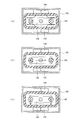
- FIG. 1 is a sectional view showing an example of an electromagnetic switch according to the present invention
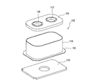
- FIG. 2 is an exploded perspective view of an arc extinguishing chamber.
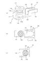
- reference numeral 10 denotes an electromagnetic contactor.
- the electromagnetic contactor 10 includes a contact device 100 having a contact mechanism and an electromagnet unit 200 that drives the contact device 100.
- the contact device 100 includes an arc extinguishing chamber 102 that houses the contact mechanism 101.
- the arc extinguishing chamber 102 has a metal rectangular tube body 104 having a flange 103 that protrudes outward at a metal lower end portion, and a flat plate shape that closes the upper end of the metal rectangular tube body 104.
- a fixed contact supporting insulating substrate 105 made of a ceramic insulating substrate.
- the metal rectangular tube 104 is fixed by being sealed and bonded to an upper magnetic yoke 210 of an electromagnet unit 200 whose flange 103 is described later.
- through holes 106 and 107 through which a pair of fixed contacts 111 and 112, which will be described later, are inserted at a central portion are formed at a predetermined interval.
- a metallization process is applied to positions around the through-holes 106 and 107 on the upper surface side of the fixed contact supporting insulating substrate 105 and a position in contact with the metal rectangular cylinder 104 on the lower surface side.
- a plurality of fixed contact supporting insulating substrates 105 are arranged vertically and horizontally on a plane, and a metal foil (for example, a copper foil) is placed around the through holes 106 and 107 and at a position in contact with the metal rectangular cylinder 104. Foil).
- the contact mechanism 101 includes a pair of fixed contacts 111 and 112 that are inserted into and fixed to the through holes 106 and 107 of the fixed contact support insulating substrate 105 of the arc extinguishing chamber 102.
- Each of the fixed contacts 111 and 112 includes a support conductor portion 114 having a flange portion projecting outward at an upper end inserted through the through holes 106 and 107 of the fixed contact support insulating substrate 105, and the support conductor portion 114.
- a C-shaped portion 115 which is connected and disposed on the lower surface side of the fixed contact supporting insulating substrate 105 and having an inner side open.
- the C-shaped portion 115 includes an upper plate portion 116 that extends outward along the lower surface of the fixed contact supporting insulating substrate 105, an intermediate plate portion 117 that extends downward from the outer end portion of the upper plate portion 116, and the intermediate plate.
- the support conductor portion 114 and the C-shaped portion 115 include a pin 114 a that protrudes from the lower end surface of the support conductor portion 114 in the through hole 120 formed in the upper plate portion 116 of the C-shaped portion 115. In the inserted state, it is fixed, for example, by brazing.
- the fixing of the support conductor portion 114 and the C-shaped portion 115 is not limited to brazing, but the pin 114a is fitted into the through hole 120, a male screw is formed on the pin 114a, and a female screw is formed on the through hole 120. The two may be screwed together.
- an insulating cover 121 made of a synthetic resin material that restricts the generation of an arc is attached to each of the C-shaped portions 115 of the fixed contacts 111 and 112. As shown in FIGS. 3A and 3B, the insulating cover 121 covers the inner peripheral surfaces of the upper plate portion 116 and the intermediate plate portion 117 of the C-shaped portion 115. The insulating cover 121 extends upward and outward from the L-shaped plate portion 122 along the inner peripheral surfaces of the upper plate portion 116 and the intermediate plate portion 117, and the front and rear end portions of the L-shaped plate portion 122, respectively.
- the insulating cover 121 is in a state in which the fitting portion 125 is opposed to the small diameter portion 114b of the support conductor portion 114 of the fixed contacts 111 and 112.
- the fitting portion 125 is fitted to the small diameter portion 114 b of the support conductor portion 114 by pushing the insulating cover 121.
- the arc extinguishing chamber 102 after the fixed contacts 111 and 112 are attached is opened from the upper opening with the fixed contact supporting insulating substrate 105 on the lower side.
- the insulating cover 121 is inserted between the fixed contacts 111 and 112 in a state where the insulating cover 121 is turned upside down with respect to FIGS.
- the movable contact 130 is arrange
- the movable contact 130 is supported by a connecting shaft 131 fixed to a movable plunger 215 of an electromagnet unit 200 described later.
- the movable contact 130 is formed with a recess 132 that protrudes downward in the vicinity of the central connection shaft 131, and a through hole 133 through which the connection shaft 131 is inserted is formed in the recess 132. Is formed.
- the connecting shaft 131 has a flange 131a protruding outward at the upper end.
- the connecting shaft 131 is inserted into the contact spring 134 from the lower end side, and then inserted into the through hole 133 of the movable contact 130 so that the upper end of the contact spring 134 is brought into contact with the flange portion 131a.
- the movable contact 130 is positioned by, for example, a C-ring 135 so as to obtain a force.
- the movable contact 130 In the released state, the movable contact 130 is in a state in which the contact portions 130a at both ends and the contact portions 118a of the lower plate portion 118 of the C-shaped portion 115 of the fixed contacts 111 and 112 are spaced apart from each other by a predetermined distance. .
- the contact portions at both ends are in contact with the contact portion 118a of the lower plate portion 118 of the C-shaped portion 115 of the fixed contacts 111 and 112 with a predetermined contact pressure by the contact spring 134 at the closing position. It is set to be.
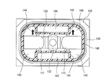
- the inner peripheral surface of the metal square tube body 104 of the arc extinguishing chamber 102 has a bottom with a square tube portion 140a and a bottom plate portion 140b formed on the lower surface side of the square tube portion 140a.
- An insulating cylinder 140 formed in a rectangular tube shape is provided.
- the insulating cylinder 140 is made of, for example, a synthetic resin, and the square cylinder part 140a and the bottom plate part 140b are integrally formed.
- Magnet storage cylinders 141 and 142 as magnet storage portions are integrally formed at positions facing the side surfaces of the movable contact 130 of the insulating cylinder 140.
- Arc extinguishing permanent magnets 143 and 144 are inserted and fixed in the magnet housing cylinders 141 and 142.
- the arc extinguishing permanent magnets 143 and 144 are magnetized so that their opposing magnetic pole surfaces are the same pole, for example, N pole, in the thickness direction. Further, the arc extinguishing permanent magnets 143 and 144 have opposite ends in the left-right direction, as shown in FIG. 5, between the contact portions 118a of the fixed contacts 111 and 112 and the contact portions of the movable contact 130, respectively. It is set to be slightly inside. Arc extinguishing spaces 145 and 146 are formed in the left-right direction of the magnet housing cylinders 141 and 142, that is, outside the longitudinal direction of the movable contact, respectively.
- the insulating cylinder 140 has a function of positioning the arc extinguishing permanent magnets 143 and 144 by the magnet housing cylinders 141 and 42, a protection function for protecting the arc extinguishing permanent magnets 143 and 144 from arcs, and external rigidity. It has an insulating function to cut off the influence of the arc on the metal rectangular cylinder 104 that enhances.
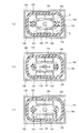
- the arc extinguishing permanent magnets 143 and 144 can be brought close to the movable contact 130. Therefore, the magnetic flux ⁇ from the N-pole side of both arc extinguishing permanent magnets 143 and 144 causes the contact portion 118a of the fixed contacts 111 and 112 and the contact of the movable contact 130 as shown in FIG. The portion facing the portion 130a is traversed with a large magnetic flux density from the inside to the outside in the left-right direction.
- the direction of the current in the applied state is as shown in FIG. 6B. Then, it flows to the fixed contact 112 through the movable contact 130. Then, when the movable contact 130 is separated from the fixed contacts 111 and 112 upward from the charged state to be released, the contact portion 118a of the fixed contacts 111 and 112 and the contact portion 130a of the movable contact 130 are An arc is generated between them.
- This arc is stretched to the arc extinguishing space 145 side on the arc extinguishing permanent magnet 143 side by the magnetic flux ⁇ from the arc extinguishing permanent magnets 143 and 144 as shown in FIG.
- the arc extinguishing spaces 145 and 146 are formed wide by the thickness of the arc extinguishing permanent magnets 143 and 144, a long arc length can be taken and the arc can be extinguished reliably.
- the electromagnet unit 200 includes a U-shaped magnetic yoke 201 that is flat when viewed from the side, and a cylindrical auxiliary yoke 203 is fixed to the center of the bottom plate portion 202 of the magnetic yoke 201. Yes.
- a spool 204 is disposed outside the cylindrical auxiliary yoke 203.
- the spool 204 includes a central cylindrical portion 205 that passes through the cylindrical auxiliary yoke 203, a lower flange portion 206 that protrudes radially outward from the lower end portion of the central cylindrical portion 205, and a little more than the upper end of the central cylindrical portion 205.
- the upper flange portion 207 protrudes radially outward from the lower side.
- An exciting coil 208 is wound around a storage space formed by the central cylindrical portion 205, the lower flange portion 206, and the upper flange portion 207.
- the upper magnetic yoke 210 is fixed between the upper ends of the magnetic yoke 201 serving as the open end.
- the upper magnetic yoke 210 is formed with a through hole 210 a facing the central cylindrical portion 205 of the spool 204 at the central portion.
- a movable plunger 215 having a return spring 214 disposed between the bottom portion and the bottom plate portion 202 of the magnetic yoke 201 is slidably disposed.
- the movable plunger 215 is formed with a peripheral flange portion 216 protruding outward in the radial direction at an upper end portion protruding upward from the upper magnetic yoke 210.
- a permanent magnet 220 having a square outer shape and a circular center opening 221 formed in an annular shape is fixed so as to surround the peripheral flange portion 216 of the movable plunger 215.
- the permanent magnet 220 is magnetized so that the upper end side is, for example, an N pole and the lower end side is an S pole in the vertical direction, that is, the thickness direction.
- the shape of the central opening 221 of the permanent magnet 220 may be a shape that matches the shape of the peripheral flange portion 216, and the shape of the outer peripheral surface may be an arbitrary shape such as a circle or a rectangle.
- An auxiliary yoke 225 having a through hole 224 having the same outer shape as the permanent magnet 220 and having an inner diameter smaller than the outer diameter of the peripheral flange portion 216 of the movable plunger 215 is fixed to the upper end surface of the permanent magnet 220.
- the peripheral flange 216 of the movable plunger 215 is in contact with the lower surface of the auxiliary yoke 225.
- a connecting shaft 131 that supports the movable contact 130 is screwed to the upper end surface of the movable plunger 215.
- the movable plunger 215 is covered with a cap 230 made of a non-magnetic material and formed in a bottomed cylindrical shape, and a flange portion 231 formed to extend radially outward from the open end of the cap 230 has an upper magnetic yoke.
- the lower surface of 210 is sealed and joined.
- a sealed container is formed in which the arc extinguishing chamber 102 and the cap 230 are communicated with each other via the through hole 210 a of the upper magnetic yoke 210.
- a gas such as hydrogen gas, nitrogen gas, a mixed gas of hydrogen and nitrogen, air, or SF 6 is sealed in a sealed container formed by the arc extinguishing chamber 102 and the cap 230.
- the fixed contact 111 is connected to a power supply source that supplies a large current, for example, and the fixed contact 112 is connected to a load.
- the exciting coil 208 in the electromagnet unit 200 is in a non-excited state and the electromagnet unit 200 is in a released state in which no exciting force for lowering the movable plunger 215 is generated.
- the movable plunger 215 is urged upward by the return spring 214 away from the upper magnetic yoke 210.
- the attractive force due to the magnetic force of the permanent magnet 220 is applied to the auxiliary yoke 225, and the peripheral flange 216 of the movable plunger 215 is attracted. For this reason, the upper surface of the peripheral flange portion 216 of the movable plunger 215 is in contact with the lower surface of the auxiliary yoke 225.
- the contact part 130a of the movable contact 130 of the contact mechanism 101 connected to the movable plunger 215 via the connection shaft 131 is spaced apart from the contact part 118a of the fixed contacts 111 and 112 upward by a predetermined distance. .
- the current path between the stationary contacts 111 and 112 is in a disconnected state, and the contact mechanism 101 is in an open state.
- both the urging force by the return spring 214 and the attractive force by the annular permanent magnet 220 are acting on the movable plunger 215, so that the movable plunger 215 is inadvertently caused by external vibration or impact. Therefore, it is possible to reliably prevent malfunction.
- the fixed contactors 111 and 112 have a C-shaped portion 115 formed by the upper plate portion 116, the intermediate plate portion 117, and the lower plate portion 118.
- a current in the reverse direction flows between the plate portion 118 and the movable contact 130 facing the plate portion 118.
- the movable contact 130 is connected to the contact portion 118a of the fixed contacts 111 and 112 according to the Fleming left-hand rule.
- the pressing Lorentz force can be generated.
- the movable contact 130 connected via the connecting shaft 131 rises.
- the movable contact 130 is in contact with the stationary contacts 111 and 112 while the contact pressure is applied by the contact spring 134.
- the contact pressure of the contact spring 134 disappears, the movable contact 130 is in a state of opening opening in which the movable contact 130 is separated upward from the fixed contacts 111 and 112.
- the insulating cover 121 can be attached to the fixed contacts 111 and 112 simply by fitting the fitting portion 125 to the small diameter portion 114b of the fixed contacts 111 and 112. Can be easily mounted.
- the opposing magnetic pole faces of the arc extinguishing permanent magnets 143 and 144 are N poles and the outside thereof is the S pole, the magnetic flux emitted from the N poles is shown in FIG.
- the arc generation part of the contact part 118a of the fixed contactor 112 and the contact part 130a of the movable contactor 130 crosses from the inside to the outside in the longitudinal direction of the movable contactor 130 and reaches the S pole to form a magnetic field.
- the magnetic fluxes of the arc extinguishing permanent magnets 143 and 144 are both between the contact portion 118a of the fixed contact 111 and the contact portion 130a of the movable contact 130, and between the contact portion 118a of the fixed contact 112 and the contact of the movable contact 130.
- the portions 130a cross in the opposite directions in the longitudinal direction of the movable contact 130. For this reason, between the contact part 118a of the fixed contactor 111 and the contact part 130a of the movable contactor 130, as shown in FIG. 6B, the current I flows from the fixed contactor 111 side to the movable contactor 130 side. As it flows, the direction of the magnetic flux ⁇ becomes the direction from the inside toward the outside.
- an arc generated between the contact portion 118a of the fixed contact 111 and the contact portion 130a of the movable contact 130 passes through the arc extinguishing space 145 from the side surface of the contact portion 118a of the fixed contact 111. It is greatly stretched so as to reach the upper surface side of the movable contact 130 and is extinguished. Further, in the arc extinguishing space 145, the magnetic flux is downward and upward with respect to the direction of the magnetic flux between the contact portion 118a of the fixed contact 111 and the contact portion 130a of the movable contact 130 on the lower side and the upper side. Will tilt.
- the arc stretched to the arc extinguishing space 145 by the tilted magnetic flux is further stretched in the direction of the corner of the arc extinguishing space 145, the arc length can be increased, and good interruption performance can be obtained. .
- the arc extinguishing space 145 is directed to the arc extinguishing space 145 side perpendicular to the longitudinal direction of the movable contact 130 and perpendicular to the opening / closing direction of the contact portion 118a of the fixed contact 112 and the movable contact 130.
- a large Lorentz force F acts.
- an arc generated between the contact portion 118a of the fixed contact 112 and the movable contact 130 passes through the arc extinguishing space 145 from the upper surface side of the movable contact 130 to the fixed contact 112. It is greatly stretched to reach the side and extinguished. Further, in the arc extinguishing space 145, as described above, on the lower side and the upper side, the lower side and the upper side with respect to the direction of the magnetic flux between the contact part 118a of the stationary contact 112 and the contact part 130a of the movable contact 130 and The magnetic flux is inclined upward.
- the arc stretched to the arc extinguishing space 145 by the tilted magnetic flux is further stretched in the direction of the corner of the arc extinguishing space 145, the arc length can be increased, and good interruption performance can be obtained. .
- the insulating cylinder 140 can cover and insulate the inner peripheral surface of the metal arc extinguishing chamber 102, there is no short circuit of the arc when the current is interrupted, and the current can be reliably interrupted. Furthermore, the insulation function, the positioning function of the arc extinguishing permanent magnets 143 and 144, the arc extinguishing permanent magnets 143 and 144 are protected from arcing, and the arc is prevented from reaching the external metal square tube body 104. Since the insulating function to be performed can be performed by one insulating cylinder 140, the manufacturing cost can be reduced.
- the distance between the side edge of the movable contact 130 and the inner peripheral surface of the insulating cylindrical body 140 can be increased by the thickness of the arc extinguishing permanent magnets 143 and 144, a sufficient arc extinguishing space 145 is sufficient. And 146 can be provided, and the arc can be surely extinguished. Further, movable contact guide members 148 and 149 that slide in contact with the side edges of the movable contact protrude at positions facing the movable contact 130 of the magnet housing cylinders 141 and 142 that house the arc extinguishing permanent magnets 143 and 144. Since it is formed, the rotation of the movable contact 130 can be reliably prevented.
- the present invention is not limited to this, and FIG.
- the bottom plate portion 253 in which the magnet housing portion 252 of the base member 251 is formed is combined with four side plate portions 256 to 259 constituting side walls at the front and rear and left and right ends, and these side plate portions 256 to 259 are combined. 259 may be connected to form the insulating cylinder 140.
- the side wall portion is divided into four side plate portions 256 to 259, the manufacturing becomes easier as compared with the case where the whole is integrally formed.
- a square tube body in which the four side plate portions 256 to 259 are integrated may be formed.
- the opposing magnetic pole surface of the arc extinguishing permanent magnets 143 and 144 was made into the N pole was demonstrated, it is not limited to this, The arc extinguishing permanent magnets 143 and 144 are not limited thereto. Even if the opposite magnetic pole surface is made the S pole, the same effect as the above-described embodiment can be obtained except that the arc crossing direction of the magnetic flux and the direction of the Lorentz force are reversed.
- an L-shaped portion 160 having a shape in which the upper plate portion 116 in the C-shaped portion 115 is omitted may be coupled to the support conductor portion 114.
- a recessed part is shown. 132 may be omitted to form a flat plate.
- the connecting shaft 131 is screwed to the movable plunger 215.
- the movable plunger 215 and the connecting shaft 131 may be integrally formed.
- connection between the connecting shaft 131 and the movable contact 130 forms a flange portion 131a at the tip of the connecting shaft 131, and the lower end of the movable contact 130 is inserted into the C after inserting the contact spring 134 and the movable contact 130.
- it is not limited to this. That is, a positioning large-diameter portion that protrudes in the radial direction is formed at the C-ring position of the connecting shaft 131, and the contact spring 134 is disposed after the movable contact 130 is brought into contact with the positioning large-diameter portion. You may make it fix with a ring.
- the sealed container was comprised with the arc-extinguishing chamber 102 and the cap 230, and the case where gas was enclosed in this sealed container was demonstrated, it is not limited to this,
- block is If it is low, gas filling may be omitted.
- an electromagnetic contactor capable of improving productivity, simplifying a brazing jig, and further suppressing flatness and warping of a plate portion supporting a fixed contact. Can be provided.
- Electromagnetic contactor 100 ... Contact apparatus, 101 ... Contact mechanism, 102 ... Arc-extinguishing chamber, 104 ... Square cylinder, 105 ... Fixed contact support insulation board, 111, 112 ... Fixed contact, 114 ... Support conductor part, 115 ... C-shaped part, 116 ... Upper plate part, 117 ... Intermediate plate part, 118 ... Lower plate part, 118a ... Contact part, 121 ... Insulating cover, 122 ... L-shaped plate part, 123, 124 ... Side plate part, 125 ... Snap fitting part, 130 ... Moving contact, 130a ... Contact part, 131 ... Connecting shaft, 132 ...
Abstract
Description
前記消弧室は、少なくとも前記一対の固定接触子を固定する貫通孔及び一方の面の外周円縁にメタライズ処理によって金属箔が形成された平板状の固定接点支持絶縁基板を有し、該固定接点支持絶縁基板の金属箔に前記一対の固定接触子及び金属筒体がろう付けされて接合され、前記金属筒体の内周面に絶縁筒体が配置されていることを特徴としている。 In order to achieve the above object, an electromagnetic contactor according to an aspect of the present invention includes an arc extinguishing chamber including a contact mechanism having a pair of fixed contacts and a movable contact contacting the pair of fixed contacts. With
The arc-extinguishing chamber has at least a through-hole for fixing the pair of fixed contacts and a flat plate-like fixed contact supporting insulating substrate in which a metal foil is formed by metallization processing on an outer peripheral edge of one surface. The pair of fixed contacts and the metal cylinder are brazed and joined to the metal foil of the contact supporting insulating substrate, and the insulating cylinder is arranged on the inner peripheral surface of the metal cylinder.
この構成によると、固定接点支持絶縁基板をセラミック絶縁基板で構成するので、大量生産が可能で製作コストを低減することができる。
また、本発明の他の形態に係る電磁接触器は、前記絶縁筒体は、セラミック板を組み合わせて構成されていることを特徴としている。
この構成によると、絶縁筒体を、セラミック板を組み合わせて構成するので、製作が容易となる。 An electromagnetic contactor according to another aspect of the present invention is characterized in that the fixed contact supporting insulating substrate is formed of a ceramic insulating substrate.
According to this configuration, since the fixed contact supporting insulating substrate is formed of a ceramic insulating substrate, mass production is possible and manufacturing costs can be reduced.
Moreover, the electromagnetic contactor which concerns on the other form of this invention is characterized by the said insulation cylinder being comprised combining the ceramic board.
According to this configuration, since the insulating cylinder is configured by combining the ceramic plates, the manufacture becomes easy.
図1は本発明に係る電磁開閉器の一例を示す断面図、図2は消弧室の分解斜視図である。この図1及び図2において、10は電磁接触器であり、この電磁接触器10は接点機構を配置した接点装置100と、この接点装置100を駆動する電磁石ユニット200とで構成されている。 Hereinafter, embodiments of the present invention will be described with reference to the drawings.
FIG. 1 is a sectional view showing an example of an electromagnetic switch according to the present invention, and FIG. 2 is an exploded perspective view of an arc extinguishing chamber. 1 and 2,
金属角筒体104は、そのフランジ部103が後述する電磁石ユニット200の上部磁気ヨーク210にシール接合されて固定されている。 As is apparent from FIGS. 1 and 2, the
The metal
絶縁カバー121は、上板部116及び中間板部117の内周面に沿うL字状板部122と、このL字状板部122の前後端部からそれぞれ上方及び外方に延長してC字状部115の上板部116及び中間板部117の側面を覆う側板部123及び124と、これら側板部123及び124の上端から内方側に形成された固定接触子111及び112の支持導体部114に形成された小径部114bに嵌合する嵌合部125とを備えている。 Then, an insulating
The insulating
実際には、図4(a)に示すように、固定接触子111及び112を取付けた後の消弧室102を、固定接点支持絶縁基板105を下側とした状態で、上方の開口部から絶縁カバー121を図3(a)~(c)とは上下逆にした状態で、固定接触子111及び112間に挿入する。 Therefore, as shown in FIGS. 3A and 3B, the insulating
Actually, as shown in FIG. 4 (a), the
このように、固定接触子111及び112のC字状部115に絶縁カバー121を装着することにより、このC字状部115の内周面では下板部118の上面側のみが露出されて接点部118aとされている。 Next, as shown in FIG. 4B, in a state where the
As described above, by attaching the insulating
したがって、絶縁筒体140は、磁石収納筒体141及び42によるアーク消弧用永久磁石143及び144の位置決め機能と、アークからアーク消弧用永久磁石143及び144を保護する保護機能及び外部の剛性を高める金属角筒体104に対するアークの影響を遮断する絶縁機能を備えている。 In addition, movable contact guide members 148 and 149 are formed protrudingly so as to slide in contact with the side edges of the
Therefore, the insulating
電磁石ユニット200は、図1に示すように、側面から見て扁平なU字形状の磁気ヨーク201を有し、この磁気ヨーク201の底板部202の中央部に円筒状補助ヨーク203が固定されている。この円筒状補助ヨーク203の外側にスプール204が配置されている。 However, according to the above-described embodiment, the arc extinguishing
As shown in FIG. 1, the
そして、スプール204の中央円筒部205内に、底部と磁気ヨーク201の底板部202との間に復帰スプリング214を配設した可動プランジャ215が上下に摺動可能に配設されている。この可動プランジャ215には、上部磁気ヨーク210から上方に突出する上端部に半径方向外方に突出する周鍔部216が形成されている。 The upper
In the central
また、可動プランジャ215の上端面には可動接触子130を支持する連結軸131が螺着されている。 An
A connecting
いる。 The
今、固定接触子111が例えば大電流を供給する電力供給源に接続し、固定接触子112が負荷に接続されているものとする。
この状態で、電磁石ユニット200における励磁コイル208が非励磁状態にあって、電磁石ユニット200で可動プランジャ215を下降させる励磁力を発生していない釈放状態にあるものとする。この釈放状態では、可動プランジャ215が復帰スプリング214によって、上部磁気ヨーク210から離れる上方向に付勢される。これと同時に、永久磁石220の磁力による吸引力が補助ヨーク225に作用されて、可動プランジャ215の周鍔部216が吸引される。このため、可動プランジャ215の周鍔部216の上面が補助ヨーク225の下面に当接している。 Next, the operation of the above embodiment will be described.
Now, it is assumed that the fixed
In this state, it is assumed that the
このように、釈放状態では、可動プランジャ215に復帰スプリング214による付勢力と環状永久磁石220による吸引力との双方が作用しているので、可動プランジャ215が外部からの振動や衝撃等によって不用意に下降することがなく、誤動作を確実に防止することができる。 For this reason, the
Thus, in the released state, both the urging force by the
この可動プランジャ215の下降が、周鍔部216の下面が上部磁気ヨーク210の上面に当接することにより停止される。 When the
The lowering of the
このため、外部電力供給源の大電流が固定接触子111、可動接触子130及び固定接触子112を通じて負荷に供給される閉極状態となる。 As described above, when the
Therefore, a closed state is reached in which a large current from the external power supply source is supplied to the load through the fixed
しかしながら、固定接触子111及び112は、図1に示すように、上板部116、中間板部117及び下板部118によってC字状部115が形成されているので、上板部116及び下板部118とこれに対向する可動接触子130とで逆方向の電流が流れることになる。このため、固定接触子111及び112の下板部118が形成する磁界と可動接触子130に流れる電流の関係からフレミング左手の法則により可動接触子130を固定接触子111及び112の接点部118aに押し付けるローレンツ力を発生することができる。 At this time, an electromagnetic repulsive force is generated between the fixed
However, as shown in FIG. 1, the fixed
これによって、電磁石ユニット200で可動プランジャ215を下方に移動させる励磁力がなくなることにより、可動プランジャ215が復帰スプリング214の付勢力によって上昇し、周鍔部216が補助ヨーク225に近づくに従って環状永久磁石220の吸引力が増加する。 When the current supply to the load is cut off from the closed state of the
As a result, the exciting force that moves the
このとき、アーク消弧用永久磁石143及び144の対向磁極面がN極であり、その外側がS極であるので、このN極から出た磁束が、平面から見て図6(a)に示すように、各アーク消弧用永久磁石143及び144固定接触子111の接点部118aと可動接触子130の接点部130aとの対向部のアーク発生部を可動接触子130の長手方向に内側から外側に横切ってS極に達して磁界が形成される。同様に、固定接触子112の接点部118aと可動接触子130の接点部130aのアーク発生部を可動接触子130の長手方向に内側から外側に横切ってS極に達して磁界が形成される。 The insulating
At this time, since the opposing magnetic pole faces of the arc extinguishing
このため、固定接触子111の接点部118aと可動接触子130の接点部130aとの間では、図6(b)に示すように、電流Iが固定接触子111側から可動接触子130側に流れるとともに、磁束Φの向きが内側から外側に向かう方向となる。このため、フレミングの左手の法則によって、図6(c)に示すように、可動接触子130の長手方向と直交し且つ固定接触子111の接点部118aと可動接触子130との開閉方向と直交してアーク消弧空間145側に向かう大きなローレンツ力Fが作用する。 Therefore, the magnetic fluxes of the arc extinguishing
For this reason, between the
また、アーク消弧空間145では、その下方側及び上方側で、固定接触子111の接点部118a及び可動接触子130の接点部130a間の磁束の向きに対して下方側に及び上方側に磁束が傾くことになる。このため、傾いた磁束によってアーク消弧空間145に引き伸ばされたアークがアーク消弧空間145の隅の方向へさらに引き伸ばされ、アーク長を長くすることができ、良好な遮断性能を得ることができる。 Due to the Lorentz force F, an arc generated between the
Further, in the
また、アーク消弧空間145では、上述したように、その下方側及び上方側で、固定接触子112の接点部118a及び可動接触子130の接点部130a間の磁束の向きに対して下方側及び上方側に磁束が傾くことになる。このため、傾いた磁束によってアーク消弧空間145に引き伸ばされたアークがアーク消弧空間145の隅の方向へさらに引き伸ばされ、アーク長を長くすることができ、良好な遮断性能を得ることができる。 Due to the Lorentz force F, an arc generated between the
Further, in the
このとき、アーク消弧用永久磁石143及び144は絶縁筒体140に形成された磁石収納筒体141及び142内に配置されているので、アークが直接アーク消弧用永久磁石143及び144に接触することがない。このため、アーク消弧用永久磁石143及び144の磁気特性を安定して維持することができ、遮断性能を安定化させることができる。 On the other hand, when the
At this time, since the arc extinguishing
さらに、絶縁機能、アーク消弧用永久磁石143及び144の位置決め機能、アーク消弧用永久磁石143及び144のアークからの保護機能及び外部の金属製の角筒体104にアークが届くことを遮断する絶縁機能を1つの絶縁筒体140で行うことができるので、製造コストを低減させることができる。 Further, since the insulating
Furthermore, the insulation function, the positioning function of the arc extinguishing
さらに、アーク消弧用永久磁石143及び144を収納する磁石収納筒体141及び142の可動接触子130と対向する位置に可動接触子の側縁に摺接する可動接触子ガイド部材148及び149が突出形成されているので、可動接触子130の回動を確実に防止することができる。 Further, since the distance between the side edge of the
Further, movable contact guide members 148 and 149 that slide in contact with the side edges of the movable contact protrude at positions facing the
この場合でも、固定接触子111及び112に可動接触子130を接触させた閉極状態で、L字状部160の垂直板部を流れる電流によって生じる磁束を固定接触子111及び112と可動接触子130との接触部に作用させることができる。このため、固定接触子111及び112と可動接触子130との接触部における磁束密度を高めて電磁反発力に抗するローレンツ力を発生させることができる。 Moreover, in the said embodiment, although the case where the C-shaped
Even in this case, the magnetic flux generated by the current flowing through the vertical plate portion of the L-shaped
また、上記第1及び第2の実施形態においては、可動プランジャ215に連結軸131を螺合させる場合について説明したが、可動プランジャ215と連結軸131とを一体に形成するようにしてもよい。 Moreover, in the said embodiment, although the case where the
In the first and second embodiments, the case where the connecting
また、上記実施形態においては、消弧室102及びキャップ230で密封容器を構成し、この密封容器内にガスを封入する場合について説明したが、これに限定されるものではなく、遮断する電流が低い場合にはガス封入を省略するようにしてもよい。 In addition, the connection between the connecting
Moreover, in the said embodiment, although the sealed container was comprised with the arc-extinguishing
Claims (4)
- 一対の固定接触子とこれら一対の固定接触子に接触する可動接触子とを有する接点機構を内装する消弧室を備え、
前記消弧室は、少なくとも前記一対の固定接触子を固定する貫通孔及び一方の面の外周円縁にメタライズ処理によって金属箔が形成された平板状の固定接点支持絶縁基板を有し、該固定接点支持絶縁基板の金属箔に前記一対の固定接触子及び金属筒体がろう付けされて接合され、前記金属筒体の内周面に絶縁筒体が配置されていることを特徴とする電磁接触器。 An arc extinguishing chamber having a contact mechanism having a pair of fixed contacts and a movable contact contacting the pair of fixed contacts;
The arc-extinguishing chamber has at least a through-hole for fixing the pair of fixed contacts and a flat plate-like fixed contact supporting insulating substrate in which a metal foil is formed by metallization processing on an outer peripheral edge of one surface. The electromagnetic contact, wherein the pair of fixed contacts and the metal cylinder are brazed and joined to the metal foil of the contact supporting insulating substrate, and the insulating cylinder is disposed on the inner peripheral surface of the metal cylinder. vessel. - 前記固定接点支持絶縁基板は、セラミック絶縁基板で形成されていることを特徴とする請求項1に記載の電磁接触器。 The electromagnetic contactor according to claim 1, wherein the fixed contact supporting insulating substrate is formed of a ceramic insulating substrate.
- 前記絶縁筒体は、セラミック筒体で構成されていることを特徴とする請求項1又は2に記載の電磁接触器。 The electromagnetic contactor according to claim 1 or 2, wherein the insulating cylinder is formed of a ceramic cylinder.
- 前記絶縁筒体は、セラミック板を組み合わせて構成されていることを特徴とする請求項1又は2に記載の電磁接触器。 The electromagnetic contactor according to claim 1 or 2, wherein the insulating cylinder is configured by combining ceramic plates.
Priority Applications (6)
| Application Number | Priority Date | Filing Date | Title |
|---|---|---|---|
| KR1020137029170A KR20140022055A (en) | 2011-05-19 | 2012-05-09 | Electromagnetic contactor |
| ES12785055T ES2826999T3 (en) | 2011-05-19 | 2012-05-09 | Electromagnetic contactor |
| EP20187679.4A EP3748664B1 (en) | 2011-05-19 | 2012-05-09 | Electromagnetic contactor |
| CN201280003201.6A CN103140909B (en) | 2011-05-19 | 2012-05-09 | Electromagnetic contactor |
| US13/878,366 US8994482B2 (en) | 2011-05-19 | 2012-05-09 | Electromagnetic contactor |
| EP12785055.0A EP2711956B1 (en) | 2011-05-19 | 2012-05-09 | Electromagnetic contactor |
Applications Claiming Priority (2)
| Application Number | Priority Date | Filing Date | Title |
|---|---|---|---|
| JP2011112911A JP5689741B2 (en) | 2011-05-19 | 2011-05-19 | Magnetic contactor |
| JP2011-112911 | 2011-05-19 |
Publications (1)
| Publication Number | Publication Date |
|---|---|
| WO2012157216A1 true WO2012157216A1 (en) | 2012-11-22 |
Family
ID=47176568
Family Applications (1)
| Application Number | Title | Priority Date | Filing Date |
|---|---|---|---|
| PCT/JP2012/003041 WO2012157216A1 (en) | 2011-05-19 | 2012-05-09 | Electromagnetic contactor |
Country Status (7)
| Country | Link |
|---|---|
| US (1) | US8994482B2 (en) |
| EP (2) | EP2711956B1 (en) |
| JP (1) | JP5689741B2 (en) |
| KR (1) | KR20140022055A (en) |
| CN (1) | CN103140909B (en) |
| ES (1) | ES2826999T3 (en) |
| WO (1) | WO2012157216A1 (en) |
Cited By (2)
| Publication number | Priority date | Publication date | Assignee | Title |
|---|---|---|---|---|
| CN104704598A (en) * | 2012-12-05 | 2015-06-10 | 富士电机机器制御株式会社 | Electromagnetic contactor |
| CN104737264A (en) * | 2012-12-12 | 2015-06-24 | 富士电机机器制御株式会社 | Electromagnetic contactor |
Families Citing this family (15)
| Publication number | Priority date | Publication date | Assignee | Title |
|---|---|---|---|---|
| KR101375585B1 (en) | 2010-03-15 | 2014-03-18 | 오므론 가부시키가이샤 | Contact switching device |
| JP5134657B2 (en) * | 2010-07-27 | 2013-01-30 | 富士電機機器制御株式会社 | Contact mechanism and electromagnetic contactor using the same |
| JP5711044B2 (en) * | 2010-12-02 | 2015-04-30 | 富士電機株式会社 | Magnetic contactor, gas sealing method of magnetic contactor, and method of manufacturing magnetic contactor |
| JP5864902B2 (en) * | 2011-05-19 | 2016-02-17 | 富士電機機器制御株式会社 | Assembling method of arc extinguishing chamber of magnetic contactor |
| JP5727861B2 (en) * | 2011-05-19 | 2015-06-03 | 富士電機機器制御株式会社 | Magnetic contactor |
| JP5793048B2 (en) * | 2011-10-07 | 2015-10-14 | 富士電機株式会社 | Magnetic contactor |
| JP5856426B2 (en) * | 2011-10-07 | 2016-02-09 | 富士電機株式会社 | Contact device and electromagnetic contactor using the same |
| WO2014208098A1 (en) * | 2013-06-28 | 2014-12-31 | パナソニックIpマネジメント株式会社 | Contact point device and electromagnetic relay mounted with same |
| WO2015001710A1 (en) * | 2013-07-05 | 2015-01-08 | 富士電機株式会社 | Electromagnetic contactor |
| JP6380893B2 (en) * | 2014-06-19 | 2018-08-29 | パナソニックIpマネジメント株式会社 | Contact device and electromagnetic relay using the same |
| CN104576160A (en) * | 2014-12-18 | 2015-04-29 | 珠海康晋电气有限公司 | Solid insulating three-position isolating switch with grounding switching off capability |
| JP6464900B2 (en) * | 2015-04-13 | 2019-02-06 | 富士電機機器制御株式会社 | Magnetic contactor |
| CN105895452B (en) * | 2016-05-27 | 2017-11-10 | 浙江英洛华新能源科技有限公司 | Closed type HVDC relay |
| DE102017107441A1 (en) * | 2017-04-06 | 2018-10-11 | Schaltbau Gmbh | Switchgear with contact cover |
| US10950402B2 (en) * | 2017-10-17 | 2021-03-16 | Solarbos, Inc. | Electrical contactor |
Citations (4)
| Publication number | Priority date | Publication date | Assignee | Title |
|---|---|---|---|---|
| JP3107288B2 (en) | 1996-03-26 | 2000-11-06 | 松下電工株式会社 | Sealed contact device |
| JP2005019160A (en) * | 2003-06-25 | 2005-01-20 | Sumitomo Electric Ind Ltd | D.c. relay |
| JP2005183277A (en) * | 2003-12-22 | 2005-07-07 | Omron Corp | Supporting structure of fixed contact terminal |
| JP2010257788A (en) * | 2009-04-24 | 2010-11-11 | Panasonic Electric Works Co Ltd | Contact device |
Family Cites Families (30)
| Publication number | Priority date | Publication date | Assignee | Title |
|---|---|---|---|---|
| JPH0211704Y2 (en) | 1980-05-29 | 1990-03-28 | ||
| JPS57194421A (en) | 1981-05-26 | 1982-11-30 | Meidensha Electric Mfg Co Ltd | Vacuum breaker |
| JPH03103385A (en) | 1989-09-18 | 1991-04-30 | Nippon Steel Corp | Metallization of ceramic and bonding of ceramic to metal |
| DE10116505B4 (en) * | 2001-04-03 | 2005-04-14 | Bruker Biospin Gmbh | Integral passive shim system and method for a magnetic resonance apparatus |
| JP2003308773A (en) | 2002-04-16 | 2003-10-31 | Toyota Motor Corp | Electromagnetic relay and mounting method thereof |
| JP3985628B2 (en) * | 2002-08-09 | 2007-10-03 | オムロン株式会社 | Switchgear |
| JP2004071512A (en) * | 2002-08-09 | 2004-03-04 | Omron Corp | Switching device |
| JP2004311389A (en) * | 2003-02-21 | 2004-11-04 | Sumitomo Electric Ind Ltd | Dc relay |
| CN100439968C (en) * | 2003-05-09 | 2008-12-03 | 皇家飞利浦电子股份有限公司 | Electrowetting cells |
| JP4525153B2 (en) | 2003-06-05 | 2010-08-18 | オムロン株式会社 | Seal structure of terminal and seal material used therefor |
| JP4325393B2 (en) * | 2003-12-22 | 2009-09-02 | オムロン株式会社 | Switchgear |
| CA2569064C (en) * | 2005-03-28 | 2011-08-02 | Matsushita Electric Works, Ltd. | Contact device |
| JP4765761B2 (en) * | 2006-05-12 | 2011-09-07 | オムロン株式会社 | Electromagnetic relay |
| CN101536131B (en) * | 2006-08-21 | 2013-03-27 | 阿科林有限公司 | Medium-voltage circuit-breaker |
| WO2008033349A2 (en) * | 2006-09-11 | 2008-03-20 | Gigavac, Inc. | Sealed contactor |
| US7852178B2 (en) | 2006-11-28 | 2010-12-14 | Tyco Electronics Corporation | Hermetically sealed electromechanical relay |
| KR100841650B1 (en) * | 2006-12-29 | 2008-06-27 | 엘에스산전 주식회사 | Dc switching apparatus |
| WO2009116493A1 (en) * | 2008-03-19 | 2009-09-24 | パナソニック電工株式会社 | Contact device |
| KR20090119276A (en) * | 2008-05-15 | 2009-11-19 | 엘에스산전 주식회사 | Electromagnetic switch and making method thereof |
| JP5163317B2 (en) * | 2008-06-30 | 2013-03-13 | オムロン株式会社 | Contact device |
| JP5104599B2 (en) | 2008-06-30 | 2012-12-19 | オムロン株式会社 | Electromagnetic switchgear |
| JP5206157B2 (en) * | 2008-06-30 | 2013-06-12 | オムロン株式会社 | Electromagnetic relay |
| JP5163318B2 (en) * | 2008-06-30 | 2013-03-13 | オムロン株式会社 | Electromagnet device |
| JP5195144B2 (en) * | 2008-08-07 | 2013-05-08 | 株式会社デンソー | Electromagnetic switch |
| KR101004465B1 (en) * | 2008-09-05 | 2010-12-31 | 엘에스산전 주식회사 | Relay |
| JP2010192416A (en) * | 2009-01-21 | 2010-09-02 | Panasonic Electric Works Co Ltd | Sealed contact device |
| JP5197480B2 (en) * | 2009-05-14 | 2013-05-15 | 株式会社日本自動車部品総合研究所 | Electromagnetic relay |
| KR101018129B1 (en) * | 2009-11-13 | 2011-02-25 | 주식회사 한국전자재료 | Method for making arc chamber and power breaker having the arc chamber |
| KR101375585B1 (en) * | 2010-03-15 | 2014-03-18 | 오므론 가부시키가이샤 | Contact switching device |
| JP5437949B2 (en) * | 2010-08-11 | 2014-03-12 | 富士電機機器制御株式会社 | Contact device and electromagnetic contactor using the same |
-
2011
- 2011-05-19 JP JP2011112911A patent/JP5689741B2/en active Active
-
2012
- 2012-05-09 KR KR1020137029170A patent/KR20140022055A/en not_active Application Discontinuation
- 2012-05-09 EP EP12785055.0A patent/EP2711956B1/en active Active
- 2012-05-09 US US13/878,366 patent/US8994482B2/en active Active
- 2012-05-09 ES ES12785055T patent/ES2826999T3/en active Active
- 2012-05-09 CN CN201280003201.6A patent/CN103140909B/en active Active
- 2012-05-09 EP EP20187679.4A patent/EP3748664B1/en active Active
- 2012-05-09 WO PCT/JP2012/003041 patent/WO2012157216A1/en active Application Filing
Patent Citations (4)
| Publication number | Priority date | Publication date | Assignee | Title |
|---|---|---|---|---|
| JP3107288B2 (en) | 1996-03-26 | 2000-11-06 | 松下電工株式会社 | Sealed contact device |
| JP2005019160A (en) * | 2003-06-25 | 2005-01-20 | Sumitomo Electric Ind Ltd | D.c. relay |
| JP2005183277A (en) * | 2003-12-22 | 2005-07-07 | Omron Corp | Supporting structure of fixed contact terminal |
| JP2010257788A (en) * | 2009-04-24 | 2010-11-11 | Panasonic Electric Works Co Ltd | Contact device |
Non-Patent Citations (1)
| Title |
|---|
| See also references of EP2711956A4 |
Cited By (4)
| Publication number | Priority date | Publication date | Assignee | Title |
|---|---|---|---|---|
| CN104704598A (en) * | 2012-12-05 | 2015-06-10 | 富士电机机器制御株式会社 | Electromagnetic contactor |
| US9520246B2 (en) | 2012-12-05 | 2016-12-13 | Fuji Electric Fa Components & Systems Co., Ltd. | Electromagnetic contactor |
| CN104737264A (en) * | 2012-12-12 | 2015-06-24 | 富士电机机器制御株式会社 | Electromagnetic contactor |
| US9589739B2 (en) | 2012-12-12 | 2017-03-07 | Fuji Electric Fa Components & Systems Co., Ltd. | Electromagnetic contactor |
Also Published As
| Publication number | Publication date |
|---|---|
| JP5689741B2 (en) | 2015-03-25 |
| EP2711956B1 (en) | 2020-09-09 |
| EP3748664A1 (en) | 2020-12-09 |
| US8994482B2 (en) | 2015-03-31 |
| KR20140022055A (en) | 2014-02-21 |
| CN103140909A (en) | 2013-06-05 |
| ES2826999T3 (en) | 2021-05-19 |
| JP2012243588A (en) | 2012-12-10 |
| US20130229248A1 (en) | 2013-09-05 |
| EP2711956A1 (en) | 2014-03-26 |
| EP2711956A4 (en) | 2015-04-22 |
| EP3748664B1 (en) | 2023-05-24 |
| CN103140909B (en) | 2016-12-28 |
Similar Documents
| Publication | Publication Date | Title |
|---|---|---|
| JP5689741B2 (en) | Magnetic contactor | |
| JP5727862B2 (en) | Magnetic contactor | |
| JP5778989B2 (en) | Magnetic contactor | |
| JP5684650B2 (en) | Magnetic contactor | |
| JP5684649B2 (en) | Magnetic contactor | |
| JP5767508B2 (en) | Magnetic contactor | |
| JP5864902B2 (en) | Assembling method of arc extinguishing chamber of magnetic contactor | |
| WO2013183226A1 (en) | Electromagnetic contactor | |
| JP5986419B2 (en) | Contact device and electromagnetic switch using the same | |
| JP5727860B2 (en) | Magnetic contactor | |
| JP5727861B2 (en) | Magnetic contactor |
Legal Events
| Date | Code | Title | Description |
|---|---|---|---|
| WWE | Wipo information: entry into national phase |
Ref document number: 201280003201.6 Country of ref document: CN |
|
| 121 | Ep: the epo has been informed by wipo that ep was designated in this application |
Ref document number: 12785055 Country of ref document: EP Kind code of ref document: A1 |
|
| WWE | Wipo information: entry into national phase |
Ref document number: 2012785055 Country of ref document: EP |
|
| WWE | Wipo information: entry into national phase |
Ref document number: 13878366 Country of ref document: US |
|
| ENP | Entry into the national phase |
Ref document number: 20137029170 Country of ref document: KR Kind code of ref document: A |
|
| NENP | Non-entry into the national phase |
Ref country code: DE |