JP2012243588A - Electromagnetic contactor - Google Patents
Electromagnetic contactor Download PDFInfo
- Publication number
- JP2012243588A JP2012243588A JP2011112911A JP2011112911A JP2012243588A JP 2012243588 A JP2012243588 A JP 2012243588A JP 2011112911 A JP2011112911 A JP 2011112911A JP 2011112911 A JP2011112911 A JP 2011112911A JP 2012243588 A JP2012243588 A JP 2012243588A
- Authority
- JP
- Japan
- Prior art keywords
- contact
- fixed
- arc
- arc extinguishing
- movable
- Prior art date
- Legal status (The legal status is an assumption and is not a legal conclusion. Google has not performed a legal analysis and makes no representation as to the accuracy of the status listed.)
- Granted
Links
- 239000000758 substrate Substances 0.000 claims abstract description 34
- 230000002093 peripheral effect Effects 0.000 claims abstract description 24
- 239000011888 foil Substances 0.000 claims abstract description 7
- 238000001465 metallisation Methods 0.000 claims abstract description 6
- 239000002184 metal Substances 0.000 claims description 19
- 229910052751 metal Inorganic materials 0.000 claims description 19
- 239000000919 ceramic Substances 0.000 claims description 10
- 238000005219 brazing Methods 0.000 abstract description 12
- 238000009413 insulation Methods 0.000 abstract description 9
- 230000000452 restraining effect Effects 0.000 abstract 1
- 230000004907 flux Effects 0.000 description 17
- 239000004020 conductor Substances 0.000 description 11
- 238000004519 manufacturing process Methods 0.000 description 8
- 238000007789 sealing Methods 0.000 description 7
- 239000007789 gas Substances 0.000 description 4
- 238000000034 method Methods 0.000 description 4
- 238000003860 storage Methods 0.000 description 4
- IJGRMHOSHXDMSA-UHFFFAOYSA-N Atomic nitrogen Chemical compound N#N IJGRMHOSHXDMSA-UHFFFAOYSA-N 0.000 description 3
- UFHFLCQGNIYNRP-UHFFFAOYSA-N Hydrogen Chemical compound [H][H] UFHFLCQGNIYNRP-UHFFFAOYSA-N 0.000 description 2
- 230000005284 excitation Effects 0.000 description 2
- 239000003779 heat-resistant material Substances 0.000 description 2
- 238000005304 joining Methods 0.000 description 2
- 239000007769 metal material Substances 0.000 description 2
- 238000003825 pressing Methods 0.000 description 2
- 238000007650 screen-printing Methods 0.000 description 2
- 229920003002 synthetic resin Polymers 0.000 description 2
- 239000000057 synthetic resin Substances 0.000 description 2
- RYGMFSIKBFXOCR-UHFFFAOYSA-N Copper Chemical compound [Cu] RYGMFSIKBFXOCR-UHFFFAOYSA-N 0.000 description 1
- 239000003570 air Substances 0.000 description 1
- 238000013459 approach Methods 0.000 description 1
- 230000008033 biological extinction Effects 0.000 description 1
- 239000011889 copper foil Substances 0.000 description 1
- 229910001873 dinitrogen Inorganic materials 0.000 description 1
- 230000000694 effects Effects 0.000 description 1
- 230000005281 excited state Effects 0.000 description 1
- 239000001257 hydrogen Substances 0.000 description 1
- 229910052739 hydrogen Inorganic materials 0.000 description 1
- 239000000696 magnetic material Substances 0.000 description 1
- 230000007257 malfunction Effects 0.000 description 1
- 239000000463 material Substances 0.000 description 1
- 229910052757 nitrogen Inorganic materials 0.000 description 1
- 230000001172 regenerating effect Effects 0.000 description 1
Images


Classifications
-
- H—ELECTRICITY
- H01—ELECTRIC ELEMENTS
- H01H—ELECTRIC SWITCHES; RELAYS; SELECTORS; EMERGENCY PROTECTIVE DEVICES
- H01H9/00—Details of switching devices, not covered by groups H01H1/00 - H01H7/00
- H01H9/30—Means for extinguishing or preventing arc between current-carrying parts
- H01H9/34—Stationary parts for restricting or subdividing the arc, e.g. barrier plate
- H01H9/36—Metal parts
- H01H9/362—Mounting of plates in arc chamber
-
- H—ELECTRICITY
- H01—ELECTRIC ELEMENTS
- H01H—ELECTRIC SWITCHES; RELAYS; SELECTORS; EMERGENCY PROTECTIVE DEVICES
- H01H50/00—Details of electromagnetic relays
- H01H50/02—Bases; Casings; Covers
-
- H—ELECTRICITY
- H01—ELECTRIC ELEMENTS
- H01H—ELECTRIC SWITCHES; RELAYS; SELECTORS; EMERGENCY PROTECTIVE DEVICES
- H01H9/00—Details of switching devices, not covered by groups H01H1/00 - H01H7/00
- H01H9/30—Means for extinguishing or preventing arc between current-carrying parts
- H01H9/34—Stationary parts for restricting or subdividing the arc, e.g. barrier plate
- H01H9/346—Details concerning the arc formation chamber
-
- H—ELECTRICITY
- H01—ELECTRIC ELEMENTS
- H01H—ELECTRIC SWITCHES; RELAYS; SELECTORS; EMERGENCY PROTECTIVE DEVICES
- H01H50/00—Details of electromagnetic relays
- H01H50/02—Bases; Casings; Covers
- H01H50/023—Details concerning sealing, e.g. sealing casing with resin
- H01H2050/025—Details concerning sealing, e.g. sealing casing with resin containing inert or dielectric gasses, e.g. SF6, for arc prevention or arc extinction
-
- H—ELECTRICITY
- H01—ELECTRIC ELEMENTS
- H01H—ELECTRIC SWITCHES; RELAYS; SELECTORS; EMERGENCY PROTECTIVE DEVICES
- H01H50/00—Details of electromagnetic relays
- H01H50/54—Contact arrangements
- H01H50/546—Contact arrangements for contactors having bridging contacts
-
- H—ELECTRICITY
- H01—ELECTRIC ELEMENTS
- H01H—ELECTRIC SWITCHES; RELAYS; SELECTORS; EMERGENCY PROTECTIVE DEVICES
- H01H51/00—Electromagnetic relays
- H01H51/02—Non-polarised relays
- H01H51/04—Non-polarised relays with single armature; with single set of ganged armatures
- H01H51/06—Armature is movable between two limit positions of rest and is moved in one direction due to energisation of an electromagnet and after the electromagnet is de-energised is returned by energy stored during the movement in the first direction, e.g. by using a spring, by using a permanent magnet, by gravity
- H01H51/065—Relays having a pair of normally open contacts rigidly fixed to a magnetic core movable along the axis of a solenoid, e.g. relays for starting automobiles
-
- H—ELECTRICITY
- H01—ELECTRIC ELEMENTS
- H01H—ELECTRIC SWITCHES; RELAYS; SELECTORS; EMERGENCY PROTECTIVE DEVICES
- H01H9/00—Details of switching devices, not covered by groups H01H1/00 - H01H7/00
- H01H9/30—Means for extinguishing or preventing arc between current-carrying parts
- H01H9/44—Means for extinguishing or preventing arc between current-carrying parts using blow-out magnet
- H01H9/443—Means for extinguishing or preventing arc between current-carrying parts using blow-out magnet using permanent magnets
Abstract
Description
本発明は、固定接触子及び可動接触子を備えた接点機構を消弧室に収納した電磁接触器に関する。 The present invention relates to an electromagnetic contactor in which a contact mechanism including a fixed contact and a movable contact is accommodated in an arc extinguishing chamber.
接点機構を消弧室に収納した電磁接触器としては、例えば、セラミックのような耐熱性材料により一面を開口して箱状に形成された封止容器を有する封止接点装置が提案されている(例えば、特許文献1参照)。この特許文献1に記載の封止接点装置は、封止容器の底部の2箇所に形成された貫通穴に固定端子がろう付けにより気密接合されている。封止容器内には、固定端子に形成された固定接点に接離する可動接点を設けた可動接触子が配置されている。封止容器の開口端部が磁性金属材料により矩形状に形成され有底筒部が気密接合される第1の接合部材に、金属材料で形成された筒状の第2の接合部材を介して接続された構成を有する。 As an electromagnetic contactor in which a contact mechanism is housed in an arc extinguishing chamber, for example, a sealed contact device having a sealed container formed in a box shape by opening one side with a heat-resistant material such as ceramic has been proposed. (For example, refer to Patent Document 1). In the sealed contact device described in Patent Document 1, fixed terminals are airtightly joined by brazing to through holes formed at two locations on the bottom of the sealed container. A movable contact provided with a movable contact that contacts and separates from a fixed contact formed on the fixed terminal is arranged in the sealing container. An opening end portion of the sealing container is formed in a rectangular shape with a magnetic metal material, and a bottomed cylindrical portion is hermetically joined to a first joining member formed with a metallic material via a cylindrical second joining member. It has a connected configuration.
ところで、上記特許文献1に記載された従来例にあっては、封止容器が固定端子をろう付けするセラミックのような耐熱性材料により一面を開口して箱状に形成されている。固定端子をろう付けするためには封止容器の底部の表面にメタライズ処理を施す必要があるが、封止容器が箱状に形成されているため、封止容器を一つずつスクリーン印刷する必要があり、生産性が悪いという未解決の課題がある。また、組立時のろう付け用治具も封止容器の立体構造に対応するため、製作治具が複雑な形状となるという未解決の課題もある。さらに、封止容器の固定端子をろう付けする底部の平面度や反りの抑制も難しいという未解決の課題がある。
そこで、本発明は、上記従来例の未解決の課題に着目してなされたものであり、生産性を向上させるとともに、ろう付け用治具を簡素化することができ、さらに固定接触子を支持する板部の平面度や反りを抑制することができる電磁接触器を提供することを目的としている。
By the way, in the conventional example described in Patent Document 1, the sealing container is formed in a box shape with one surface opened by a heat resistant material such as ceramic for brazing the fixed terminal. In order to braze the fixed terminal, it is necessary to perform metallization on the bottom surface of the sealing container, but since the sealing container is formed in a box shape, it is necessary to screen-print the sealing containers one by one There is an unsolved problem that productivity is poor. Moreover, since the brazing jig at the time of assembly also corresponds to the three-dimensional structure of the sealed container, there is an unsolved problem that the manufacturing jig has a complicated shape. Furthermore, there is an unsolved problem that it is difficult to suppress the flatness and warpage of the bottom portion where the fixing terminal of the sealing container is brazed.
Therefore, the present invention has been made by paying attention to the unsolved problems of the conventional example described above, and can improve productivity, simplify the brazing jig, and further support the stationary contact. An object of the present invention is to provide an electromagnetic contactor capable of suppressing the flatness and warpage of a plate portion to be performed.
上記目的を達成するために、本発明の一の形態に係る電磁接触器は、一対の固定接触子とこれら一対の固定接触子に接触する可動接触子とを有する接点機構を内装する消弧室を備え、
前記消弧室は、少なくとも前記一対の固定接触子を固定する貫通孔及び一方の面の外周円縁にメタライズ処理によって金属箔が形成された平板状の固定接点支持絶縁基板を有し、該固定接点支持絶縁基板の金属箔に前記一対の固定接触子及び金属筒体がろう付けされて接合され、前記金属筒体の内周面に絶縁筒体が配置されていることを特徴としている。
In order to achieve the above object, an electromagnetic contactor according to an aspect of the present invention includes an arc extinguishing chamber including a contact mechanism having a pair of fixed contacts and a movable contact contacting the pair of fixed contacts. With
The arc-extinguishing chamber has at least a through-hole for fixing the pair of fixed contacts and a flat plate-like fixed contact supporting insulating substrate in which a metal foil is formed by metallization processing on an outer peripheral edge of one surface. The pair of fixed contacts and the metal cylinder are brazed and joined to the metal foil of the contact supporting insulating substrate, and the insulating cylinder is arranged on the inner peripheral surface of the metal cylinder.
この構成によると、消弧室が、固定接触子をろう付けする平板状の固定接点支持絶縁基板と、この固定接点支持絶縁基板の一面の外周縁にろう付けされた金属筒体と、この金属筒体の内側に配置された絶縁筒体とで構成されているので、固定接点支持絶縁基板をろう付けのためのメタライズ処理を施す場合に、複数の固定接点支持絶縁基板を平面上で縦横に密着して配列した状態でスクリーン印刷処理することができ、生産性を向上させることができる。また、固定接点支持絶縁基板が平板上であるので、組立やろう付け用治具を簡素化することができ、安価に構成することができる。さらに、平面度や反りの抑制や管理も容易に行うことができる。さらに、固定接点支持絶縁基板への固定接触子及び金属筒体のろう付け処理を同時に行うことができる。 According to this configuration, the arc extinguishing chamber has a flat plate-like fixed contact supporting insulating substrate for brazing the fixed contact, a metal cylinder brazed to the outer peripheral edge of one surface of the fixed contact supporting insulating substrate, and the metal Since it is composed of an insulating cylinder arranged inside the cylinder, multiple fixed contact support insulating substrates can be arranged vertically and horizontally on a flat surface when metalizing for brazing the fixed contact support insulating substrate. Screen printing processing can be performed in a closely arranged state, and productivity can be improved. In addition, since the fixed contact supporting insulating substrate is on a flat plate, assembly and brazing jigs can be simplified and can be configured at low cost. Furthermore, it is possible to easily suppress and manage flatness and warpage. Furthermore, the brazing process of the fixed contact and the metal cylinder to the fixed contact supporting insulating substrate can be performed simultaneously.
また、本発明の他の形態に係る電磁接触器は、前記固定接点支持絶縁基板は、セラミック絶縁基板で形成されていることを特徴としている。
この構成によると、固定接点支持絶縁基板をセラミック絶縁基板で構成するので、大量生産が可能で製作コストを低減することができる。
また、本発明の他の形態に係る電磁接触器は、前記絶縁筒体は、セラミック板を組み合わせて構成されていることを特徴としている。
この構成によると、絶縁筒体をセラミック板を組み合わせて構成するので、製作が容易となる。
An electromagnetic contactor according to another aspect of the present invention is characterized in that the fixed contact supporting insulating substrate is formed of a ceramic insulating substrate.
According to this configuration, since the fixed contact supporting insulating substrate is formed of a ceramic insulating substrate, mass production is possible and manufacturing costs can be reduced.
Moreover, the electromagnetic contactor which concerns on the other form of this invention is characterized by the said insulation cylinder being comprised combining the ceramic board.
According to this configuration, since the insulating cylinder is configured by combining the ceramic plates, the manufacture becomes easy.
本発明によれば、固定接点支持絶縁基板を平板状に形成するので、ろう付けのためのメタライズ処理を複数の固定接点支持絶縁基板を平板上に縦横に密着して配列させた状態でスクリーン印刷を行うことができ、生産性を格段に向上することができる。また、固定接点支持絶縁基板が平板状であるので、製作やろう付けのための治具を簡素化することができる。さらに、固定接点支持絶縁基板の平面度や反りの抑制や管理を容易に行うことができる。固定接点支持絶縁基板への固定接触子及び金属筒体のろう付けを同時に行うことができ、製作コストを低減できる。 According to the present invention, since the fixed contact supporting insulating substrate is formed in a flat plate shape, screen printing is performed in a state where a plurality of fixed contact supporting insulating substrates are arranged in close contact vertically and horizontally on the flat plate. Productivity can be improved significantly. In addition, since the fixed contact supporting insulating substrate has a flat plate shape, a jig for manufacturing and brazing can be simplified. Furthermore, it is possible to easily suppress and manage the flatness and warpage of the fixed contact supporting insulating substrate. The fixed contact and the metal cylinder can be brazed to the fixed contact supporting insulating substrate at the same time, and the manufacturing cost can be reduced.
以下、本発明の実施の形態を図面に基づいて説明する。
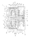
図1は本発明に係る電磁開閉器の一例を示す断面図、図2は消弧室の分解斜視図である。この図1及び図2において、10は電磁接触器であり、この電磁接触器10は接点機構を配置した接点装置100と、この接点装置100を駆動する電磁石ユニット200とで構成されている。
接点装置100は、図1及び図2から明らかなように、接点機構101を収納する消弧室102を有する。この消弧室102は、図2に示すように、金属製の下端部に外方と突出するフランジ部103を有する金属角筒体104と、この金属角筒体104の上端を閉塞する平板状のセラミック絶縁基板で構成される固定接点支持絶縁基板105とを備えている。
Hereinafter, embodiments of the present invention will be described with reference to the drawings.
FIG. 1 is a sectional view showing an example of an electromagnetic switch according to the present invention, and FIG. 2 is an exploded perspective view of an arc extinguishing chamber. 1 and 2,
As is apparent from FIGS. 1 and 2, the
金属角筒体104は、そのフランジ部103が後述する電磁石ユニット200の上部磁気ヨーク210にシール接合されて固定されている。
また、固定接点支持絶縁基板105には、中央部に後述する一対の固定接触子111及び112を挿通する貫通孔106及び107が所定間隔を保って形成されている。この固定接点支持絶縁基板105の上面側における貫通孔106及び107の周囲及び下面側における角筒体104に接触する位置にメタライズ処理が施されている。このメタライズ処理を行うには、平面上に複数の固定接点支持絶縁基板105を縦横に配列した状態で、貫通孔106及び107の周囲及び角筒体104に接触する位置に金属箔(例えば銅箔)を形成する。
The metal
Further, through
接点機構101は、図1に示すように、消弧室102の固定接点支持絶縁基板105の貫通孔106及び107に挿通されて固定された一対の固定接触子111及び112を備えている。これら固定接触子111及び112のそれぞれは、固定接点支持絶縁基板105の貫通孔106及び107に挿通される上端に外方に突出するフランジ部を有する支持導体部114と、この支持導体部114に連結されて固定接点支持絶縁基板105の下面側に配設され内方側を開放したC字状部115とを備えている。
As shown in FIG. 1, the
C字状部115は、固定接点支持絶縁基板105の下面に沿って外側に延長する上板部116とこの上板部116の外側端部から下方に延長する中間板部117と、この中間板部117の下端側から上板部116と平行に内方側すなわち固定接触子111及び112の対面方向に延長する下板部118とで中間板部117及び下板部118で形成されるL字状に上板部116を加えたC字状に形成されている。
The C-
ここで、支持導体部114とC字状部115とは、支持導体部114の下端面に突出形成されたピン114aをC字状部115の上板部116に形成された貫通孔120内に挿通した状態で例えばろう付けによって固定されている。なお、支持導体部114及びC字状部115の固定は、ろう付けに限らず、ピン114aを貫通孔120に嵌合させたり、ピン114aに雄ねじを形成し、貫通孔120に雌ねじを形成して両者を螺合させたりしてもよい。
Here, the
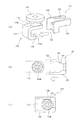
そして、固定接触子111及び112のC字状部115にそれぞれ、アークの発生を規制する合成樹脂材製の絶縁カバー121が装着されている。この絶縁カバー121は、図3(a)及び(b)に示すように、C字状部115の上板部116及び中間板部117の内周面を被覆するものである。
絶縁カバー121は、上板部116及び中間板部117の内周面に沿うL字状板部122と、このL字状板部122の前後端部からそれぞれ上方及び外方に延長してC字状部115の上板部116及び中間板部117の側面を覆う側板部123及び124と、これら側板部123及び124の上端から内方側に形成された固定接触子111及び112の支持導体部114に形成された小径部114bに嵌合する嵌合部125とを備えている。
Then, an
The insulating
したがって、絶縁カバー121が、図3(a)及び(b)に示すように、固定接触子111及び112の支持導体部114の小径部114bに嵌合部125を対向させた状態とし、次いで、図3(c)に示すように、絶縁カバー121を押し込むことにより、嵌合部125を支持導体部114の小径部114bに嵌合させる。
実際には、図4(a)に示すように、固定接触子111及び112を取付けた後の消弧室102を、固定接点支持絶縁基板105を下側とした状態で、上方の開口部から絶縁カバー121を図3(a)〜(c)とは上下逆にした状態で、固定接触子111及び112間に挿入する。
Therefore, as shown in FIGS. 3A and 3B, the insulating
Actually, as shown in FIG. 4 (a), the
次いで、図4(b)に示すように、嵌合部125を固定接点支持絶縁基板105に接触させた状態で、図4(c)に示すように、絶縁カバー121を外側に押し込むことにより、嵌合部125を固定接触子111及び112の支持導体部114の小径部114bに嵌合させて固定する。
このように、固定接触子111及び112のC字状部115に絶縁カバー121を装着することにより、このC字状部115の内周面では下板部118の上面側のみが露出されて接点部118aとされている。
Next, as shown in FIG. 4B, in a state where the
As described above, by attaching the insulating
そして、固定接触子111及び112のC字状部115内に両端部を配置するように可動接触子130が配設されている。この可動接触子130は後述する電磁石ユニット200の可動プランジャ215に固定された連結軸131に支持されている。この可動接触子130は、図1及び図5に示すように、中央部の連結軸131の近傍が下方に突出する凹部132が形成され、この凹部132に連結軸131を挿通する貫通孔133が形成されている。
And the
連結軸131は、上端に外方に突出するフランジ部131aが形成されている。この連結軸131に下端側から接触スプリング134に挿通し、次いで可動接触子130の貫通孔133を挿通して、接触スプリング134の上端をフランジ部131aに当接させこの接触スプリング134で所定の付勢力を得るように可動接触子130を例えばCリング135によって位置決めする。
The connecting
この可動接触子130は、釈放状態で、両端の接点部130aと固定接触子111及び112のC字状部115の下板部118の接点部118aとが所定間隔を保って離間した状態となる。また、可動接触子130は、投入位置で、両端の接点部が固定接触子111及び112のC字状部115の下板部118の接点部118aに、接触スプリング134による所定の接触圧で接触するように設定されている。
In the released state, the
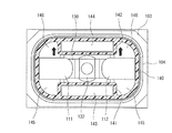
さらに、消弧室102の角筒体104の内周面には、図9に示すように、角筒部140aとこの角筒部140aの下面側に形成された底板部140bとで有底角筒状に形成された絶縁筒体140が配設されている。絶縁筒体140は例えば合成樹脂製で角筒部140a及び底板部140bが一体成形されている。そして、絶縁筒体140の可動接触子130の側面に対向する位置に磁石収納部としての磁石収納筒体141及び142が一体形成されている。この磁石収納筒体141及び142には、アーク消弧用永久磁石143及び144が挿通されて固定されている。
Further, on the inner peripheral surface of the
このアーク消弧用永久磁石143及び144は、厚み方向に互いの対向磁極面が同極例えばN極となるように着磁されている。また、アーク消弧用永久磁石143及び144は、左右方向の両端部がそれぞれ、図5に示すように、固定接触子111及び112の接点部118aと可動接触子130の接点部との対向位置より僅かに内側となるよう設定されている。そして、磁石収納筒体141及び142の左右方向すなわち可動接触子の長手方向外側にそれぞれアーク消弧空間145及び146が形成されている。
The arc extinguishing
また、磁石収納筒体141及び142の可動接触子130の両端よりの側縁と摺接して可動接触子130の回動を規制する可動接触子ガイド部材148及び149が突出形成されている。
したがって、絶縁筒体140は、磁石収納筒体141及び42によるアーク消弧用永久磁石143及び144の位置決め機能と、アークからアーク消弧用永久磁石143及び144を保護する保護機能及び外部の剛性を高める金属性の角筒体104に対するアークの影響を遮断する絶縁機能を備えている。
In addition, movable contact guide members 148 and 149 are formed protrudingly so as to slide in contact with the side edges of the
Therefore, the insulating
そして、アーク消弧用永久磁石143及び144を絶縁筒体140の内周面側に配置することにより、アーク消弧用永久磁石143及び144を可動接触子130に近接させることができる。このため、両アーク消弧用永久磁石143及び144のN極側から出る磁束φが、図6(a)に示すように、固定接触子111及び112の接点部118aと可動接触子130の接点部130aとの対向部を左右方向に内側から外側に大きな磁束密度で横切ることになる。
Further, by arranging the arc extinguishing
したがって、固定接触子111を電流供給源に接続し、固定接触子112を負荷側に接続するものとすると、投入状態の電流の方向は、図6(b)に示すように、固定接触子111から可動接触子130を通じて固定接触子112に流れることになる。そして、投入状態から可動接触子130を固定接触子111及び112から上方に離間させて釈放状態とする場合に、固定接触子111及び112の接点部118aと可動接触子130の接点部130aとの間にアークが発生する。
Therefore, when the fixed
このアークは、アーク消弧用永久磁石143及び144からの磁束φにより、図6(c)に示すように、アーク消弧用永久磁石143側のアーク消弧空間145側に引き伸ばされる。このとき、アーク消弧空間145及び146はアーク消弧用永久磁石143及び144の厚み分広く形成されているので、長いアーク長をとることができ、アークを確実に消弧することができる。
This arc is stretched to the
因みに、アーク消弧用永久磁石143及び144を、図7(a)〜(c)に示すように、絶縁筒体140の外側に配置する場合には、固定接触子111及び112の接点部118aと可動接触子130の接点部130aとの対向位置までの距離が長くなり、本実施形態と同一の永久磁石を適用した場合に、アークを横切る磁束密度が少なくなる。
Incidentally, when the arc extinguishing
このため、投入状態から釈放状態に移行する際に発生するアークに作用するローレンツ力が小さくなり、アークを十分に引き伸ばすことができなくなる。アークの消弧性能を向上させるために、アーク消弧用永久磁石143及び144の磁力を増加させる必要がある。しかも、アーク消弧用永久磁石143及び144を固定接触子111及び112と可動接触子130の接点部との距離を短くするためには絶縁筒体140の前後方向の奥行きを狭くする必要があり、アークを消弧するための十分なアーク消弧空間を確保することができないという問題点がある。
For this reason, the Lorentz force acting on the arc generated when shifting from the charged state to the released state is reduced, and the arc cannot be sufficiently stretched. In order to improve the arc extinguishing performance, it is necessary to increase the magnetic force of the arc extinguishing
しかしながら、上記実施形態によると、アーク消弧用永久磁石143及び144を絶縁筒体140の内側に配置するので、上述した絶縁筒体140の外側にアーク消弧用永久磁石143及び144を配置する場合の問題点を全て解決することができる。
電磁石ユニット200は、図1に示すように、側面から見て扁平なU字形状の磁気ヨーク201を有し、この磁気ヨーク201の底板部202の中央部に円筒状補助ヨーク203が固定されている。この円筒状補助ヨーク203の外側にスプール204が配置されている。
However, according to the above-described embodiment, the arc extinguishing
As shown in FIG. 1, the
このスプール204は、円筒状補助ヨーク203を挿通する中央円筒部205と、この中央円筒部205の下端部から半径方向外方に突出する下フランジ部206と、中央円筒部205の上端より僅かに下側から半径方向外方に突出する上フランジ部207とで構成されている。そして、中央円筒部205、下フランジ部206及び上フランジ部207で構成される収納空間に励磁コイル208が巻装されている。
The
そして、磁気ヨーク201の開放端となる上端間に上部磁気ヨーク210が固定されている。この上部磁気ヨーク210は、中央部にスプール204の中央円筒部205に対向する貫通孔210aが形成されている。
そして、スプール204の中央円筒部205内に、底部と磁気ヨーク201の底板部202との間に復帰スプリング214を配設した可動プランジャ215が上下に摺動可能に配設されている。この可動プランジャ215には、上部磁気ヨーク210から上方に突出する上端部に半径方向外方に突出する周鍔部216が形成されている。
The upper
In the central
また、上部磁気ヨーク210の上面に、例えば外形が方形で円形の中心開口221を有して環状に形成された永久磁石220が可動プランジャ215の周鍔部216を囲むように固定されている。この永久磁石220は上下方向すなわち厚み方向に上端側を例えばN極とし、下端側をS極とするように着磁されている。なお、永久磁石220の貫通孔221の形状は周鍔部216の形状に合わせた形状とし、外周面の形状は円形、方形等の任意の形状とすることができる。
Further, on the upper surface of the upper
そして、永久磁石220の上端面に、永久磁石220と同一外形で可動プランジャ215の周鍔部216の外径より小さい内径の貫通孔224を有する補助ヨーク225が固定されている。この補助ヨーク225の下面に可動プランジャ215の周鍔部216が当接されている。
また、可動プランジャ215の上端面には可動接触子130を支持する連結軸131が螺着されている。
An
A connecting
そして、可動プランジャ215が非磁性体製で有底筒状に形成されたキャップ230で覆われ、このキャップ230の開放端に半径方向外方に延長して形成されたフランジ部231が上部磁気ヨーク210の下面にシール接合されている。これによって、消弧室102及びキャップ230が上部磁気ヨーク210の貫通孔210aを介して連通される密封容器が形成されている。そして、消弧室102及びキャップ230で形成される密封容器内に水素ガス、窒素ガス、水素及び窒素の混合ガス、空気、SF6等のガスが封入されている。
The
次に、上記実施形態の動作を説明する。
今、固定接触子111が例えば大電流を供給する電力供給源に接続し、固定接触子112が負荷に接続されているものとする。
この状態で、電磁石ユニット200における励磁コイル208が非励磁状態にあって、電磁石ユニット200で可動プランジャ215を下降させる励磁力を発生していない釈放状態にあるものとする。この釈放状態では、可動プランジャ215が復帰スプリング214によって、上部磁気ヨーク210から離れる上方向に付勢される。これと同時に、永久磁石220の磁力による吸引力が補助ヨーク225に作用されて、可動プランジャ215の周鍔部216が吸引される。このため、可動プランジャ215の周鍔部216の上面が補助ヨーク225の下面に当接している。
Next, the operation of the above embodiment will be described.
Now, it is assumed that the fixed
In this state, it is assumed that the
このため、可動プランジャ215に連結軸131を介して連結されている接点機構101の可動接触子130の接点部130aが固定接触子111及び112の接点部118aから上方に所定距離だけ離間している。このため、固定接触子111及び112間の電流路が遮断状態にあり、接点機構101が開極状態となっている。
このように、釈放状態では、可動プランジャ215に復帰スプリング214による付勢力と環状永久磁石220による吸引力との双方が作用しているので、可動プランジャ215が外部からの振動や衝撃等によって不用意に下降することがなく、誤動作を確実に防止することができる。
For this reason, the
Thus, in the released state, both the urging force by the
この釈放状態から、電磁石ユニット200の励磁コイル208を励磁すると、この電磁石ユニット200で励磁力を発生させて、可動プランジャ215を復帰スプリング214の付勢力及び環状永久磁石220の吸引力に抗して下方に押し下げる。
この可動プランジャ215の下降が、周鍔部216の下面が上部磁気ヨーク210の上面に当接することにより停止される。
When the
The lowering of the
このように、可動プランジャ215が下降することにより、可動プランジャ215に連結軸131を介して連結されている可動接触子130も下降し、その接点部130aが固定接触子111及び112の接点部118aに接触スプリング134の接触圧で接触する。
このため、外部電力供給源の大電流が固定接触子111、可動接触子130及び固定接触子112を通じて負荷に供給される閉極状態となる。
このとき、固定接触子111及び112と可動接触子130との間に可動接触子130を開極させる方向の電磁反発力が発生する。
As described above, when the
For this reason, a closed state is reached in which a large current from the external power supply source is supplied to the load through the fixed
At this time, an electromagnetic repulsive force is generated between the fixed
しかしながら、固定接触子111及び112は、図1に示すように、上板部116、中間板部117及び下板部118によってC字状部115が形成されているので、上板部116及び下板部118とこれに対向する可動接触子130とで逆方向の電流が流れることになる。このため、固定接触子111及び112の下板部118が形成する磁界と可動接触子130に流れる電流の関係からフレミング左手の法則により可動接触子130を固定接触子111及び112の接点部118aに押し付けるローレンツ力を発生することができる。
However, as shown in FIG. 1, the fixed
このローレンツ力によって、固定接触子111及び112の接点部118aと可動接触子130の接点部130a間に発生する開極方向の電磁反発力に抗することが可能となり、可動接触子130の接点部130aが開極することを確実に防止することができる。このため、可動接触子130を支持する接触スプリング134の押圧力を小さくすることができ、これに応じて励磁コイル208で発生する推力も小さくすることができ、電磁接触器全体の構成を小型化することができる。
By this Lorentz force, it becomes possible to resist the electromagnetic repulsion force in the opening direction generated between the
この接点機構101の閉極状態から、負荷への電流供給を遮断する場合には、電磁石ユニット200の励磁コイル208の励磁を停止する。
これによって、電磁石ユニット200で可動プランジャ215を下方に移動させる励磁力がなくなることにより、可動プランジャ215が復帰スプリング214の付勢力によって上昇し、周鍔部216が補助ヨーク225に近づくに従って環状永久磁石220の吸引力が増加する。
When the current supply to the load is cut off from the closed state of the
As a result, the exciting force that moves the
この可動プランジャ215が上昇することにより、連結軸131を介して連結された可動接触子130が上昇する。これに応じて接触スプリング134で接触圧を与えている間は可動接触子130が固定接触子111及び112に接触している。その後、接触スプリング134の接触圧がなくなった時点で可動接触子130が固定接触子111及び112から上方に離間する開極開始状態となる。
As the
この開極開始状態となると、固定接触子111及び112の接点部118aと可動接触子130の接点部130aとの間にアークが発生し、このアークによって電流の通電状態が継続される。このとき、固定接触子111及び112のC字状部115の上板部116及び中間板部117を覆う絶縁カバー121が装着されているので、アークが固定接触子111及び112の接点部118aと可動接触子130の接点部130aとの間のみに発生させることができる。このため、アークが固定接触子111及び112のC字状部115上を動くことを確実に防止してアークの発生状態を安定させることができ、消弧性能を向上させることができる。しかも、固定接触子111及び112の両側面も絶縁カバー121で覆われているので、アークの先端が短絡することも確実に防止することができる。
When this contact opening start state is reached, an arc is generated between the
そして、絶縁カバー121は、嵌合部125を、固定接触子111及び112の小径部114bに嵌合させるだけで、固定接触子111及び112に装着することができ、固定接触子111及び112への装着を容易に行うことができる。
このとき、アーク消弧用永久磁石143及び144の対向磁極面がN極であり、その外側がS極であるので、このN極から出た磁束が、平面から見て図6(a)に示すように、各アーク消弧用永久磁石143及び144固定接触子111の接点部118aと可動接触子130の接点部130aとの対向部のアーク発生部を可動接触子130の長手方向に内側から外側に横切ってS極に達して磁界が形成される。同様に、固定接触子112の接点部118aと可動接触子130の接点部130aのアーク発生部を可動接触子130の長手方向に内側から外側に横切ってS極に達して磁界が形成される。
The insulating
At this time, since the opposing magnetic pole faces of the arc extinguishing
したがって、アーク消弧用永久磁石143及び144の磁束がともに固定接触子111の接点部118a及び可動接触子130の接点部130a間と、固定接触子112の接点部118a及び可動接触子130の接点部130a間を可動接触子130の長手方向で互いに逆方向に横切ることになる。
このため、固定接触子111の接点部118aと可動接触子130の接点部130aとの間では、図6(b)に示すように、電流Iが固定接触子111側から可動接触子130側に流れるとともに、磁束Φの向きが内側から外側に向かう方向となる。このため、フレミングの左手の法則によって、図6(c)に示すように、可動接触子130の長手方向と直交し且つ固定接触子111の接点部118aと可動接触子130との開閉方向と直交してアーク消弧空間145側に向かう大きなローレンツ力Fが作用する。
Therefore, the magnetic fluxes of the arc extinguishing
For this reason, between the
このローレンツ力Fによって、固定接触子111の接点部118aと可動接触子130の接点部130aとの間に発生したアークが、固定接触子111の接点部118aの側面からアーク消弧空間145内を通って可動接触子130の上面側に達するように大きく引き伸ばされて消弧される。
また、アーク消弧空間145では、その下方側及び上方側で、固定接触子111の接点部118a及び可動接触子130の接点部130a間の磁束の向きに対して下方側に及び上方側に磁束が傾くことになる。このため、傾いた磁束によってアーク消弧空間145に引き伸ばされたアークがアーク消弧空間145の隅の方向へさらに引き伸ばされ、アーク長を長くすることができ、良好な遮断性能を得ることができる。
Due to the Lorentz force F, an arc generated between the
Further, in the
一方、固定接触子112の接点部118aと可動接触子130との間では、図6(b)に示すように、電流が可動接触子130側から固定接触子112側に流れるとともに、磁束Φの向きが内側から外側に向かう右方向となる。このため、フレミングの左手の法則によって、可動接触子130の長手方向と直交し且つ固定接触子112の接点部118aと可動接触子130との開閉方向と直交してアーク消弧空間145側に向かう大きなローレンツ力Fが作用する。
On the other hand, between the
このローレンツ力Fによって、固定接触子112の接点部118aと可動接触子130との間に発生したアークが、可動接触子130の上面側からアーク消弧空間145内を通って固定接触子112の側面側に達するように大きく引き伸ばされて消弧される。
また、アーク消弧空間145では、上述したように、その下方側及び上方側で、固定接触子112の接点部118a及び可動接触子130の接点部130a間の磁束の向きに対して下方側及び上方側に磁束が傾くことになる。このため、傾いた磁束によってアーク消弧空間145に引き伸ばされたアークがアーク消弧空間145の隅の方向へさらに引き伸ばされ、アーク長を長くすることができ、良好な遮断性能を得ることができる。
Due to the Lorentz force F, an arc generated between the
Further, in the
一方、電磁接触器10の投入状態で、負荷側から直流電源側に回生電流が流れている状態で、釈放状態とする場合には、前述した図6(b)における電流の方向が逆となることから、ローレンツ力Fがアーク消弧空間146側に作用し、アークがアーク消弧空間146側に引き伸ばされることを除いては同様の消弧機能が発揮される。
このとき、アーク消弧用永久磁石143及び144は絶縁筒体140に形成された磁石収納筒体141及び142内に配置されているので、アークが直接アーク消弧用永久磁石143及び144に接触することがない。このため、アーク消弧用永久磁石143及び144の磁気特性を安定して維持することができ、遮断性能を安定化させることができる。
On the other hand, when the
At this time, since the arc extinguishing
また、絶縁筒体140によって、金属製の消弧室102の内周面を覆って絶縁できるので、電流遮断時のアークの短絡がなく、確実に電流遮断を行うことができる。
さらに、絶縁機能、アーク消弧用永久磁石143及び144の位置決め機能、アーク消弧用永久磁石143及び144のアークからの保護機能及び外部の金属製の角筒体104にアークが届くことを遮断する絶縁機能を1つの絶縁筒体140で行うことができるので、製造コストを低減させることができる。
Further, since the insulating
Furthermore, the insulation function, the positioning function of the arc extinguishing
また、可動接触子130の側縁と、絶縁ケース140の内周面との距離をアーク消弧用永久磁石143及び144の厚み分、長くすることができるので、十分なアーク消弧空間145及び146を設けることができ、アークの消弧を確実に行うことができる。
さらに、アーク消弧用永久磁石143及び144を収納する磁石収納筒体141及び142の可動接触子130と対向する位置に可動接触子の側縁に摺接する可動接触子ガイド部材148及び149が突出形成されているので、可動接触子130の回動を確実に防止することができる。
Further, since the distance between the side edge of the
Further, movable contact guide members 148 and 149 that slide in contact with the side edges of the movable contact protrude at positions facing the
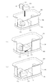
なお、上記実施形態においては、絶縁筒体140が、底板部140aと角筒体140bとを一体に形成して構成されている場合について説明したが、これに限定されるものではなく、図8に示すように、ベース部材251の磁石収納部252を形成した底板部253に、前後及び左右端部に側壁を構成する4枚の側板部256〜259を組み合わせて配置し、これら側板部256〜259を連結することよって絶縁筒体140を形成するようにしてもよい。この場合には、側壁部を4枚の側板部256〜259に分割するので、全体を一体形成する場合に比較して製造が容易となる。さらには、4枚の側板部256〜259を一体化した角筒体を形成するようにしてもよい。
In the above embodiment, the case where the insulating
また、上記実施形態においては、アーク消弧用永久磁石143及び144の対向磁極面をN極とした場合について説明したが、これに限定されるものではなく、アーク消弧用永久磁石143及び144の対向磁極面をS極とするようにしても、磁束のアーク横切り方向及びローレンツ力の方向が逆方向となることを除いては上述した実施形態と同様の効果を得ることができる。
Moreover, in the said embodiment, although the case where the opposing magnetic pole surface of the arc extinguishing
また、上記実施形態においては、固定接触子111及び112にC字状部115を形成する場合について説明したが、これに限定されるものではなく、図9(a)及び(b)に示すように、支持導体部114にC字状部115における上板部116を省略した形状となるL字状部160を連結するようにしてもよい。
この場合でも、固定接触子111及び112に可動接触子130を接触させた閉極状態で、L字状部160の垂直板部を流れる電流によって生じる磁束を固定接触子111及び112と可動接触子130との接触部に作用させることができる。このため、固定接触子111及び112と可動接触子130との接触部における磁束密度を高めて電磁反発力に抗するローレンツ力を発生させることができる。
Moreover, in the said embodiment, although the case where the C-shaped
Even in this case, the magnetic flux generated by the current flowing through the vertical plate portion of the L-shaped
また、上記実施形態においては、可動接触子130が中央部に凹部132を有する場合について説明したが、これに限定されるものではなく、図10(a)及び(b)に示すように、凹部132を省略して平板状に形成するようにしてもよい。
また、上記第1及び第2の実施形態においては、可動プランジャ215に連結軸131を螺合させる場合について説明したが、可動プランジャ215と連結軸131とを一体に形成するようにしてもよい。
Moreover, in the said embodiment, although the case where the
In the first and second embodiments, the case where the connecting
また、連結軸131と可動接触子130との連結が、連結軸131の先端部にフランジ部131aを形成し、接触スプリング134及び可動接触子130を挿通してから可動接触子130の下端をCリングで固定する場合について説明したが、これに限定されるものではない。すなわち、連結軸131のCリング位置に半径方向に突出する位置決め大径部を形成し、これに可動接触子130を当接させてから接触スプリング134を配置し、この接触スプリング134の上端をCリングによって固定するようにしてもよい。
また、上記実施形態においては、消弧室102及びキャップ230で密封容器を構成し、この密封容器内にガスを封入する場合について説明したが、これに限定されるものではなく、遮断する電流が低い場合にはガス封入を省略するようにしてもよい。
In addition, the connection between the connecting
Moreover, in the said embodiment, although the sealed container was comprised with the arc-extinguishing
10…電磁接触器、100…接点装置、101…接点機構、102…消弧室、104…角筒体、105…固定接点支持絶縁基板、111,112…固定接触子、114…支持導体部、115…C字状部、116…上板部、117…中間板部、118…下板部、118a…接点部、121…絶縁カバー、122…L字状板部、123,124…側板部、125…スナップフィット部、130…可動接触子、130a…接点部、131…連結軸、132…凹部、134…接触スプリング、140…絶縁筒体、141,142…磁石収納ポケット、143,144…アーク消弧用永久磁石、145,146…アーク消弧空間、160…L字状部、200…電磁石ユニット、201…磁気ヨーク、203…円筒状補助ヨーク、204…スプール、208…励磁コイル、210…上部磁気ヨーク、214…復帰スプリング、215…可動プランジャ、216…周鍔部、220…永久磁石、225…補助ヨーク、230…キャップ
DESCRIPTION OF
Claims (4)
前記消弧室は、少なくとも前記一対の固定接触子を固定する貫通孔及び一方の面の外周円縁にメタライズ処理によって金属箔が形成された平板状の固定接点支持絶縁基板を有し、該固定接点支持絶縁基板の金属箔に前記一対の固定接触子及び金属筒体がろう付けされて接合され、前記金属筒体の内周面に絶縁筒体が配置されていることを特徴とする電磁接触器。 An arc extinguishing chamber having a contact mechanism including a pair of fixed contacts and a movable contact contacting the pair of fixed contacts;
The arc-extinguishing chamber has at least a through-hole for fixing the pair of fixed contacts and a flat plate-like fixed contact supporting insulating substrate in which a metal foil is formed by metallization processing on an outer peripheral edge of one surface. The electromagnetic contact, wherein the pair of fixed contacts and the metal cylinder are brazed and joined to the metal foil of the contact supporting insulating substrate, and the insulating cylinder is disposed on the inner peripheral surface of the metal cylinder. vessel.
Priority Applications (8)
| Application Number | Priority Date | Filing Date | Title |
|---|---|---|---|
| JP2011112911A JP5689741B2 (en) | 2011-05-19 | 2011-05-19 | Magnetic contactor |
| PCT/JP2012/003041 WO2012157216A1 (en) | 2011-05-19 | 2012-05-09 | Electromagnetic contactor |
| KR1020137029170A KR20140022055A (en) | 2011-05-19 | 2012-05-09 | Electromagnetic contactor |
| ES12785055T ES2826999T3 (en) | 2011-05-19 | 2012-05-09 | Electromagnetic contactor |
| EP20187679.4A EP3748664B1 (en) | 2011-05-19 | 2012-05-09 | Electromagnetic contactor |
| CN201280003201.6A CN103140909B (en) | 2011-05-19 | 2012-05-09 | Electromagnetic contactor |
| US13/878,366 US8994482B2 (en) | 2011-05-19 | 2012-05-09 | Electromagnetic contactor |
| EP12785055.0A EP2711956B1 (en) | 2011-05-19 | 2012-05-09 | Electromagnetic contactor |
Applications Claiming Priority (1)
| Application Number | Priority Date | Filing Date | Title |
|---|---|---|---|
| JP2011112911A JP5689741B2 (en) | 2011-05-19 | 2011-05-19 | Magnetic contactor |
Publications (2)
| Publication Number | Publication Date |
|---|---|
| JP2012243588A true JP2012243588A (en) | 2012-12-10 |
| JP5689741B2 JP5689741B2 (en) | 2015-03-25 |
Family
ID=47176568
Family Applications (1)
| Application Number | Title | Priority Date | Filing Date |
|---|---|---|---|
| JP2011112911A Active JP5689741B2 (en) | 2011-05-19 | 2011-05-19 | Magnetic contactor |
Country Status (7)
| Country | Link |
|---|---|
| US (1) | US8994482B2 (en) |
| EP (2) | EP2711956B1 (en) |
| JP (1) | JP5689741B2 (en) |
| KR (1) | KR20140022055A (en) |
| CN (1) | CN103140909B (en) |
| ES (1) | ES2826999T3 (en) |
| WO (1) | WO2012157216A1 (en) |
Cited By (3)
| Publication number | Priority date | Publication date | Assignee | Title |
|---|---|---|---|---|
| JP2016004757A (en) * | 2014-06-19 | 2016-01-12 | パナソニックIpマネジメント株式会社 | Contact device, electromagnetic relay using the same, and method of manufacturing contact device |
| JP2016201304A (en) * | 2015-04-13 | 2016-12-01 | 富士電機機器制御株式会社 | Electromagnetic contactor |
| JP2017120793A (en) * | 2013-07-05 | 2017-07-06 | 富士電機株式会社 | Electromagnetic contactor |
Families Citing this family (14)
| Publication number | Priority date | Publication date | Assignee | Title |
|---|---|---|---|---|
| KR101375585B1 (en) | 2010-03-15 | 2014-03-18 | 오므론 가부시키가이샤 | Contact switching device |
| JP5134657B2 (en) * | 2010-07-27 | 2013-01-30 | 富士電機機器制御株式会社 | Contact mechanism and electromagnetic contactor using the same |
| JP5711044B2 (en) * | 2010-12-02 | 2015-04-30 | 富士電機株式会社 | Magnetic contactor, gas sealing method of magnetic contactor, and method of manufacturing magnetic contactor |
| JP5864902B2 (en) * | 2011-05-19 | 2016-02-17 | 富士電機機器制御株式会社 | Assembling method of arc extinguishing chamber of magnetic contactor |
| JP5727861B2 (en) * | 2011-05-19 | 2015-06-03 | 富士電機機器制御株式会社 | Magnetic contactor |
| JP5793048B2 (en) * | 2011-10-07 | 2015-10-14 | 富士電機株式会社 | Magnetic contactor |
| JP5856426B2 (en) * | 2011-10-07 | 2016-02-09 | 富士電機株式会社 | Contact device and electromagnetic contactor using the same |
| JP6119216B2 (en) * | 2012-12-05 | 2017-04-26 | 富士電機機器制御株式会社 | Magnetic contactor |
| JP6171320B2 (en) | 2012-12-12 | 2017-08-02 | 富士電機機器制御株式会社 | Magnetic contactor |
| WO2014208098A1 (en) * | 2013-06-28 | 2014-12-31 | パナソニックIpマネジメント株式会社 | Contact point device and electromagnetic relay mounted with same |
| CN104576160A (en) * | 2014-12-18 | 2015-04-29 | 珠海康晋电气有限公司 | Solid insulating three-position isolating switch with grounding switching off capability |
| CN105895452B (en) * | 2016-05-27 | 2017-11-10 | 浙江英洛华新能源科技有限公司 | Closed type HVDC relay |
| DE102017107441A1 (en) * | 2017-04-06 | 2018-10-11 | Schaltbau Gmbh | Switchgear with contact cover |
| US10950402B2 (en) * | 2017-10-17 | 2021-03-16 | Solarbos, Inc. | Electrical contactor |
Family Cites Families (34)
| Publication number | Priority date | Publication date | Assignee | Title |
|---|---|---|---|---|
| JPH0211704Y2 (en) | 1980-05-29 | 1990-03-28 | ||
| JPS57194421A (en) | 1981-05-26 | 1982-11-30 | Meidensha Electric Mfg Co Ltd | Vacuum breaker |
| JPH03103385A (en) | 1989-09-18 | 1991-04-30 | Nippon Steel Corp | Metallization of ceramic and bonding of ceramic to metal |
| JP3107288B2 (en) | 1996-03-26 | 2000-11-06 | 松下電工株式会社 | Sealed contact device |
| DE10116505B4 (en) * | 2001-04-03 | 2005-04-14 | Bruker Biospin Gmbh | Integral passive shim system and method for a magnetic resonance apparatus |
| JP2003308773A (en) | 2002-04-16 | 2003-10-31 | Toyota Motor Corp | Electromagnetic relay and mounting method thereof |
| JP3985628B2 (en) * | 2002-08-09 | 2007-10-03 | オムロン株式会社 | Switchgear |
| JP2004071512A (en) * | 2002-08-09 | 2004-03-04 | Omron Corp | Switching device |
| JP2004311389A (en) * | 2003-02-21 | 2004-11-04 | Sumitomo Electric Ind Ltd | Dc relay |
| CN100439968C (en) * | 2003-05-09 | 2008-12-03 | 皇家飞利浦电子股份有限公司 | Electrowetting cells |
| JP4525153B2 (en) | 2003-06-05 | 2010-08-18 | オムロン株式会社 | Seal structure of terminal and seal material used therefor |
| JP2005019160A (en) * | 2003-06-25 | 2005-01-20 | Sumitomo Electric Ind Ltd | D.c. relay |
| JP4325393B2 (en) * | 2003-12-22 | 2009-09-02 | オムロン株式会社 | Switchgear |
| JP4375012B2 (en) * | 2003-12-22 | 2009-12-02 | オムロン株式会社 | Support structure for fixed contact terminals |
| CA2569064C (en) * | 2005-03-28 | 2011-08-02 | Matsushita Electric Works, Ltd. | Contact device |
| JP4765761B2 (en) * | 2006-05-12 | 2011-09-07 | オムロン株式会社 | Electromagnetic relay |
| CN101536131B (en) * | 2006-08-21 | 2013-03-27 | 阿科林有限公司 | Medium-voltage circuit-breaker |
| WO2008033349A2 (en) * | 2006-09-11 | 2008-03-20 | Gigavac, Inc. | Sealed contactor |
| US7852178B2 (en) | 2006-11-28 | 2010-12-14 | Tyco Electronics Corporation | Hermetically sealed electromechanical relay |
| KR100841650B1 (en) * | 2006-12-29 | 2008-06-27 | 엘에스산전 주식회사 | Dc switching apparatus |
| WO2009116493A1 (en) * | 2008-03-19 | 2009-09-24 | パナソニック電工株式会社 | Contact device |
| KR20090119276A (en) * | 2008-05-15 | 2009-11-19 | 엘에스산전 주식회사 | Electromagnetic switch and making method thereof |
| JP5163317B2 (en) * | 2008-06-30 | 2013-03-13 | オムロン株式会社 | Contact device |
| JP5104599B2 (en) | 2008-06-30 | 2012-12-19 | オムロン株式会社 | Electromagnetic switchgear |
| JP5206157B2 (en) * | 2008-06-30 | 2013-06-12 | オムロン株式会社 | Electromagnetic relay |
| JP5163318B2 (en) * | 2008-06-30 | 2013-03-13 | オムロン株式会社 | Electromagnet device |
| JP5195144B2 (en) * | 2008-08-07 | 2013-05-08 | 株式会社デンソー | Electromagnetic switch |
| KR101004465B1 (en) * | 2008-09-05 | 2010-12-31 | 엘에스산전 주식회사 | Relay |
| JP2010192416A (en) * | 2009-01-21 | 2010-09-02 | Panasonic Electric Works Co Ltd | Sealed contact device |
| JP5140030B2 (en) * | 2009-04-24 | 2013-02-06 | パナソニック株式会社 | Contact device |
| JP5197480B2 (en) * | 2009-05-14 | 2013-05-15 | 株式会社日本自動車部品総合研究所 | Electromagnetic relay |
| KR101018129B1 (en) * | 2009-11-13 | 2011-02-25 | 주식회사 한국전자재료 | Method for making arc chamber and power breaker having the arc chamber |
| KR101375585B1 (en) * | 2010-03-15 | 2014-03-18 | 오므론 가부시키가이샤 | Contact switching device |
| JP5437949B2 (en) * | 2010-08-11 | 2014-03-12 | 富士電機機器制御株式会社 | Contact device and electromagnetic contactor using the same |
-
2011
- 2011-05-19 JP JP2011112911A patent/JP5689741B2/en active Active
-
2012
- 2012-05-09 KR KR1020137029170A patent/KR20140022055A/en not_active Application Discontinuation
- 2012-05-09 EP EP12785055.0A patent/EP2711956B1/en active Active
- 2012-05-09 US US13/878,366 patent/US8994482B2/en active Active
- 2012-05-09 ES ES12785055T patent/ES2826999T3/en active Active
- 2012-05-09 CN CN201280003201.6A patent/CN103140909B/en active Active
- 2012-05-09 EP EP20187679.4A patent/EP3748664B1/en active Active
- 2012-05-09 WO PCT/JP2012/003041 patent/WO2012157216A1/en active Application Filing
Cited By (3)
| Publication number | Priority date | Publication date | Assignee | Title |
|---|---|---|---|---|
| JP2017120793A (en) * | 2013-07-05 | 2017-07-06 | 富士電機株式会社 | Electromagnetic contactor |
| JP2016004757A (en) * | 2014-06-19 | 2016-01-12 | パナソニックIpマネジメント株式会社 | Contact device, electromagnetic relay using the same, and method of manufacturing contact device |
| JP2016201304A (en) * | 2015-04-13 | 2016-12-01 | 富士電機機器制御株式会社 | Electromagnetic contactor |
Also Published As
| Publication number | Publication date |
|---|---|
| JP5689741B2 (en) | 2015-03-25 |
| EP2711956B1 (en) | 2020-09-09 |
| EP3748664A1 (en) | 2020-12-09 |
| US8994482B2 (en) | 2015-03-31 |
| KR20140022055A (en) | 2014-02-21 |
| CN103140909A (en) | 2013-06-05 |
| ES2826999T3 (en) | 2021-05-19 |
| US20130229248A1 (en) | 2013-09-05 |
| EP2711956A1 (en) | 2014-03-26 |
| EP2711956A4 (en) | 2015-04-22 |
| EP3748664B1 (en) | 2023-05-24 |
| WO2012157216A1 (en) | 2012-11-22 |
| CN103140909B (en) | 2016-12-28 |
Similar Documents
| Publication | Publication Date | Title |
|---|---|---|
| JP5689741B2 (en) | Magnetic contactor | |
| JP5727862B2 (en) | Magnetic contactor | |
| JP5778989B2 (en) | Magnetic contactor | |
| JP5684650B2 (en) | Magnetic contactor | |
| JP5684649B2 (en) | Magnetic contactor | |
| JP5767508B2 (en) | Magnetic contactor | |
| JP5864902B2 (en) | Assembling method of arc extinguishing chamber of magnetic contactor | |
| JP5727860B2 (en) | Magnetic contactor | |
| WO2013183226A1 (en) | Electromagnetic contactor | |
| WO2013153815A1 (en) | Contact device and electromagnetic switch using same | |
| JP5727861B2 (en) | Magnetic contactor |
Legal Events
| Date | Code | Title | Description |
|---|---|---|---|
| A621 | Written request for application examination |
Free format text: JAPANESE INTERMEDIATE CODE: A621 Effective date: 20140414 |
|
| TRDD | Decision of grant or rejection written | ||
| A01 | Written decision to grant a patent or to grant a registration (utility model) |
Free format text: JAPANESE INTERMEDIATE CODE: A01 Effective date: 20150106 |
|
| A61 | First payment of annual fees (during grant procedure) |
Free format text: JAPANESE INTERMEDIATE CODE: A61 Effective date: 20150129 |
|
| R150 | Certificate of patent or registration of utility model |
Ref document number: 5689741 Country of ref document: JP Free format text: JAPANESE INTERMEDIATE CODE: R150 |
|
| S111 | Request for change of ownership or part of ownership |
Free format text: JAPANESE INTERMEDIATE CODE: R313117 |
|
| R350 | Written notification of registration of transfer |
Free format text: JAPANESE INTERMEDIATE CODE: R350 |
|
| R250 | Receipt of annual fees |
Free format text: JAPANESE INTERMEDIATE CODE: R250 |
|
| R250 | Receipt of annual fees |
Free format text: JAPANESE INTERMEDIATE CODE: R250 |
|
| R250 | Receipt of annual fees |
Free format text: JAPANESE INTERMEDIATE CODE: R250 |
|
| R250 | Receipt of annual fees |
Free format text: JAPANESE INTERMEDIATE CODE: R250 |
|
| S531 | Written request for registration of change of domicile |
Free format text: JAPANESE INTERMEDIATE CODE: R313531 |
|
| R350 | Written notification of registration of transfer |
Free format text: JAPANESE INTERMEDIATE CODE: R350 |
|
| R250 | Receipt of annual fees |
Free format text: JAPANESE INTERMEDIATE CODE: R250 |
|
| R250 | Receipt of annual fees |
Free format text: JAPANESE INTERMEDIATE CODE: R250 |
|
| R250 | Receipt of annual fees |
Free format text: JAPANESE INTERMEDIATE CODE: R250 |