WO2012157212A1 - 3次元画像表示装置、および3次元画像表示方法 - Google Patents
3次元画像表示装置、および3次元画像表示方法 Download PDFInfo
- Publication number
- WO2012157212A1 WO2012157212A1 PCT/JP2012/003030 JP2012003030W WO2012157212A1 WO 2012157212 A1 WO2012157212 A1 WO 2012157212A1 JP 2012003030 W JP2012003030 W JP 2012003030W WO 2012157212 A1 WO2012157212 A1 WO 2012157212A1
- Authority
- WO
- WIPO (PCT)
- Prior art keywords
- dimensional image
- image display
- display device
- display unit
- unit
- Prior art date
- Legal status (The legal status is an assumption and is not a legal conclusion. Google has not performed a legal analysis and makes no representation as to the accuracy of the status listed.)
- Ceased
Links
Images



Classifications
-
- G—PHYSICS
- G02—OPTICS
- G02B—OPTICAL ELEMENTS, SYSTEMS OR APPARATUS
- G02B7/00—Mountings, adjusting means, or light-tight connections, for optical elements
- G02B7/001—Counterbalanced structures, e.g. surgical microscopes
-
- G—PHYSICS
- G02—OPTICS
- G02B—OPTICAL ELEMENTS, SYSTEMS OR APPARATUS
- G02B27/00—Optical systems or apparatus not provided for by any of the groups G02B1/00 - G02B26/00, G02B30/00
- G02B27/01—Head-up displays
- G02B27/0149—Head-up displays characterised by mechanical features
-
- H—ELECTRICITY
- H04—ELECTRIC COMMUNICATION TECHNIQUE
- H04N—PICTORIAL COMMUNICATION, e.g. TELEVISION
- H04N13/00—Stereoscopic video systems; Multi-view video systems; Details thereof
- H04N13/30—Image reproducers
- H04N13/332—Displays for viewing with the aid of special glasses or head-mounted displays [HMD]
- H04N13/344—Displays for viewing with the aid of special glasses or head-mounted displays [HMD] with head-mounted left-right displays
-
- G—PHYSICS
- G02—OPTICS
- G02B—OPTICAL ELEMENTS, SYSTEMS OR APPARATUS
- G02B27/00—Optical systems or apparatus not provided for by any of the groups G02B1/00 - G02B26/00, G02B30/00
- G02B27/01—Head-up displays
- G02B27/0101—Head-up displays characterised by optical features
- G02B2027/0132—Head-up displays characterised by optical features comprising binocular systems
- G02B2027/0134—Head-up displays characterised by optical features comprising binocular systems of stereoscopic type
Definitions
- the present invention relates to a three-dimensional image display apparatus that displays a three-dimensional image using binocular parallax and a three-dimensional image display method.
- a display device that displays an image projected from a projection device on a spherical screen in order to display a realistic image is known (see, for example, Patent Document 1). Further, in order to further increase the sense of reality, a technique for displaying a three-dimensional image, that is, a stereoscopic image is also used.
- a wavelength-separated color glasses system that uses special glasses having a special function and separates left and right images using a difference in wavelength of light.
- Various types are known, such as a polarization-separation type polarizing glasses method that separates left and right images using a difference in polarization state, and a time-division type glasses method that alternately displays left and right images.
- the display device that separates the left and right images using the special glasses as described above is to display the right-eye image and the left-eye image on one display unit in a temporally or spatially manner. Regardless of which method is used, it is difficult to reliably prevent crosstalk. For this reason, there is a tendency to have a bad influence on the user such as a sense of reality and visual fatigue.
- small display devices are provided at the positions of the left and right eyes of a glasses-type frame or goggles-type frame, and a glasses-type display that displays left and right images separately, a head-mounted display (HMD), or the like is used.
- HMD head-mounted display
- this type of display device needs to incorporate various components necessary for displaying an image into a glasses-type frame or a goggle-type frame, which increases the weight and impairs the comfort when worn. It had the problem of being prone to this.
- the present invention has been made in view of the above points, and its purpose is to reduce the burden of supporting the weight of the display device while reliably preventing crosstalk between the left and right images, and to improve the comfort at the time of wearing.
- An object of the present invention is to provide a three-dimensional image display device that can be made to operate.
- the first invention provides: A display unit that separately displays a left-eye image and a right-eye image; A support that supports at least a portion of the weight of the display, A positioning unit that causes the display unit to follow the movement of the eye position; It is provided with.
- the left-eye image and the right-eye image are separately displayed on the display unit, so that crosstalk between the left and right images is reliably prevented. Moreover, even if such a display unit is used, at least a part of the weight of the display unit is supported by the support unit, so that the burden on the viewer to support the weight of the display device can be reduced, and the comfort during wearing is reduced Can be improved.
- the second invention is A three-dimensional image display device according to a first invention,
- the support part has an arm member having a tip part connected to the display part.
- the third invention is A three-dimensional image display device according to a second invention,
- the arm member has a plurality of rigid rod members and a connecting member that couples the rigid rod members so as to be relatively movable,
- the connecting member is configured to bias the rigid rod member in a direction that supports at least a part of the weight of the display unit.
- the fourth invention is: A three-dimensional image display device according to a third invention,
- the connecting member is formed in a joint shape for connecting the rigid rod members so as to be relatively rotatable.
- the fifth invention is: A three-dimensional image display device according to a second invention,
- the arm member includes a bar-like member having elasticity in a bending direction, and is configured to support at least a part of the weight of the display unit by the elastic force of the bar-like member.
- the sixth invention is: A three-dimensional image display device according to a first invention,
- the support portion includes an elastic member that urges the display portion upward by a tensile force.
- the seventh invention A three-dimensional image display device according to a sixth invention,
- the elastic member has a string-like member suspended from above.
- the eighth invention A three-dimensional image display device according to any one of the first to seventh inventions,
- the support portion has a distal end portion connected to the display portion and a proximal end portion fixed to a seat on which a viewer is seated.
- the weight of the display unit can be easily supported by the support unit with a relatively simple configuration.
- the ninth invention A three-dimensional image display device according to any one of the first to eighth aspects,
- the positioning unit is configured to cause the display unit to follow the movement of the eye position when the display unit is pressed against a face.
- the tenth invention is A three-dimensional image display device according to a ninth invention,
- the positioning portion has a contact portion that is provided on the display portion and contacts the face,
- the support portion is configured to bias the contact portion in a direction in which the contact portion is pressed against the face.
- the eleventh invention is A three-dimensional image display device according to a ninth invention,
- the positioning part is An abutting part attached to the display unit and abutting on the face; And a vine member that is attached to the display unit and is hooked on an ear.
- the twelfth invention A three-dimensional image display device according to a ninth invention,
- the positioning part is An abutting part attached to the display unit and abutting on the face; And a belt member that is attached to the display unit and spans the back of the head.
- the display unit can follow the movement of the eye position without exerting a large force on the viewer's face or head, so that crosstalk between the left and right images can be reliably prevented and the sense of presence can be realized. It is possible to easily display a certain video.
- the thirteenth invention A three-dimensional image display device according to any one of the first to twelfth inventions,
- the display unit includes a retinal scanning image display device.
- the fourteenth invention is A three-dimensional image display device according to any one of the first to twelfth inventions,
- the display unit includes an image display unit that displays a visible image on a display surface.
- the fifteenth invention The three-dimensional image display device according to any one of the first invention to the fourteenth invention, Furthermore, a receiving unit for receiving a remote control signal for controlling the operation of the three-dimensional image display device is provided.
- the burden of supporting the weight of the display device can be reduced while the crosstalk between the left and right images is reliably prevented, and the comfort at the time of wearing can be improved.
- FIG. 3 is a side view illustrating a usage state of the three-dimensional image display device according to the first embodiment.
- 1 is a perspective view illustrating a detailed configuration of a three-dimensional image display device according to Embodiment 1.
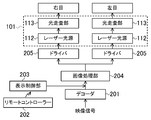
- FIG. 2 is a block diagram illustrating a functional configuration of the three-dimensional image display device according to the first embodiment.
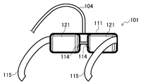
- 6 is a perspective view illustrating a detailed configuration of a three-dimensional image display apparatus according to Embodiment 2.
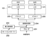
- FIG. 6 is a block diagram illustrating a functional configuration of a three-dimensional image display apparatus according to Embodiment 2.
- FIG. FIG. 6 is a perspective view illustrating a detailed configuration of a three-dimensional image display device according to a third embodiment.
- Embodiment 1 In the three-dimensional image display apparatus according to the first embodiment, as shown in FIG. 1, the display unit 101 is supported by an articulated arm member 103 attached to a seat 102 on which a viewer is seated. .
- the display unit 101 includes, for example, as shown in FIG. 2, a frame 111 having a shape similar to normal glasses, and separate laser light sources 112 and optical scanning units 113 respectively corresponding to the left and right eyes.
- a retinal scanning display provided with is attached.
- the retinal scanning display projects and displays an image by guiding the light beam modulated and emitted from the laser light source 112 onto the retina of the eye while deflecting the light beam by the optical scanning unit 113 and scanning the retina.
- the frame 111 is also provided with a nose pad 114 that contacts the viewer's nose.
- the arm member 103 that supports the display unit 101 includes three rigid rod members 103a to 103c and a display unit 101 that are rotatably attached to each other by joint-like connecting members 103d to 103f. Yes. Further, the connecting members 103d to 103f support at least a part of the weight of the display unit 101 by a spring or the like (not shown), and have a direction and size that slightly presses the nose pad 114 of the display unit 101 against the face of the viewer. The rigid rod members 103a to 103c are urged by force to cause the display unit 101 to follow the movement of the position of the eyes (face). It should be noted that the number of joints of the arm member 103 is not limited to three, and may be smaller, or may be increased to increase the degree of freedom and facilitate position adjustment according to the seating height, posture, etc. of the viewer. May be.
- a decoder 201 decodes a video signal input from a video signal source and generates a signal for driving the display unit 101.
- the remote controller 202 is detachably provided at, for example, the tip of the armrest of the seat 102, and is used to select a desired image quality mode of the viewer, to select a desired content in the case of video on demand, or in the case of a game application.
- an operation signal by infrared rays, radio waves, or ultrasonic waves is output. Note that wired communication via a cable along the arm member 103 may be performed.
- the display control unit 203 receives the operation signal and performs display control according to the operation of the viewer. Note that content selection or the like may be received by a device or the like serving as a video signal source to perform various processes.
- the image processing unit 204 performs image signal processing for the right eye and image signal processing for the left eye.
- the driver 205 modulates the light emission intensity of the laser light source 112 (for example, three colors of RGB) in accordance with the signal output from the image processing unit.
- the optical scanning unit 113 includes a galvano mirror or MEMS (Micro Electro Mechanical Systems) mirror, a lens, and the like, performs deflection in synchronization with the modulation of the laser light, and irradiates a desired position on the viewer's retina with the laser light It is supposed to be.
- a galvano mirror or MEMS (Micro Electro Mechanical Systems) mirror performs deflection in synchronization with the modulation of the laser light, and irradiates a desired position on the viewer's retina with the laser light It is supposed to be.
- the laser light source 112 and the optical scanning unit 113 are incorporated in the display unit 101 and the other components are dispersedly arranged on the arm member 103, the sheet 102, etc.
- the sheath weight can be easily reduced, in this embodiment, since the weight of the display unit 101 is supported by the arm member 103, other components such as the display control unit 203 and the image processing unit 204 are also included in the display unit 101. Even if it is incorporated in the device, the burden on the viewer is reduced, so that a flexible device design can be performed without worrying about the weight limit of the display unit 101 or the like.
- Such a three-dimensional image display device as described above is a device premised on use in, for example, a movie theater or an amusement park, so that it is easy to achieve high functionality and high added value.
- the same video may be provided to a plurality of viewers in a lump, or each viewer may be able to view a favorite video like video on demand.
- the weight of the display unit 101 is supported by the arm member 103 and the horizontal positioning is performed by the nose pad 114 with a relatively small force, thereby reducing the visual burden on the viewer.
- the burden on the head, neck, etc. that supports the weight of the display unit 101 is reduced, and the comfort during wearing is reduced. Can be improved.
- the weight of the device increases in order to increase the functionality of the retinal operation display, for example, to widen the scanning range, it is not necessary for the user to support the weight with the head. You can enjoy high-quality and high-quality images in a relaxed and comfortable state without giving them.
- the three-dimensional image display apparatus of the second embodiment has an LCD (liquid crystal display) or an organic EL (electroluminescent) display instead of the retinal scanning display as shown in FIG.
- the image display unit 121 is used.
- a flexible rod-like elastic arm member 104 that is flexible and supports the weight of the display unit 101 by having elasticity in the bending direction is used.
- the frame 111 of the display unit 101 is provided with a vine 115 similar to normal glasses.
- the display unit 101 is implemented except that an image display unit 121 is provided in place of the laser light source 112 and the optical scanning unit 113 as in the first embodiment. It can be configured in the same manner as in the first mode.
- an image display unit 121 for example, an image including a backlight can be used, but if an edge light type is used, it is particularly easy to reduce the thickness.
- the display unit 101 can be positioned mainly in the horizontal direction by placing the vine 115 on the ear and bringing the nose pad 114 into contact with the nose.
- the member 104 may support the display unit 101 so that the weight of the display unit 101 is compensated and the display unit 101 can move in a substantially horizontal direction with a relatively small force.
- the burden of supporting the weight of the display unit 101 can be reduced while the crosstalk-free three-dimensional image is displayed by the left and right independent image display units 121, and the comfort at the time of wearing can be improved.
- Embodiment 3 For example, as shown in FIG. 6, the goggle frame 131 to which the image display unit 121 is attached is used, and the belt member 132 is stretched over the back of the head and positioned. It may be made.
- the weight of the display unit 101 is still supported by the arm member 104, and it is only necessary to perform positioning in a substantially horizontal direction with a relatively small force by the nose pad 114 and the belt member 132.
- the comfort at the time of wearing can be improved while displaying a crosstalk-free three-dimensional image.
- the arm member 104 is not limited to completely supporting the weight of the display unit 101. If at least a part of the arm member 104 is supplementarily supported, the support burden on the viewer is reduced accordingly. .
- the support unit for supporting the weight of the display unit 101 is not limited to the joint-type or flexible elastic arm member 104 as described above, and a string-like elastic member hanging from above may be used. Good. More specifically, for example, a tension spring or a tension rubber that can be easily moved in the horizontal direction by a tensile force so that the display unit 101 is suspended may be used.
- feedback control using a sensor and actuator that detects the position of the head, etc. reduces the force acting on the viewer by automatically following the eye position while supporting the weight of the display unit. You can also
- the joint-type arm member 103 as in the first embodiment is used in the three-dimensional image display device according to the second and third embodiments, or conversely, a flexible elastic arm as in the second and third embodiments.
- the member 103 may be used for the three-dimensional image display apparatus according to the first embodiment.
- the present invention is useful for a three-dimensional image display device that displays a three-dimensional image using binocular parallax.
Landscapes
- Physics & Mathematics (AREA)
- General Physics & Mathematics (AREA)
- Optics & Photonics (AREA)
- Engineering & Computer Science (AREA)
- Multimedia (AREA)
- Signal Processing (AREA)
- Testing, Inspecting, Measuring Of Stereoscopic Televisions And Televisions (AREA)
Abstract
左右画像のクロストークを確実に防止しつつ、表示装置の重量を支える負担を軽減するため、表示部101を支持するアーム部材103は、3本の剛体棒部材103a~103c、および表示部101が、それぞれ関節状の連結部材103d~103fによって互いに回動自在に取り付けられて構成されている。連結部材103d~103fは、ばね等により、表示部101の重量を支え、かつ、表示部101を視聴者の顔面にわずかに押し付ける方向および大きさの力で、各剛体棒部材103a~103cを付勢するようになっている。
Description
本発明は、両眼視差を利用して3次元画像を表示する3次元画像表示装置、および3次元画像表示方法に関するものである。
従来より、臨場感のある映像を表示させるために、投射装置から投射された映像を球面状スクリーンに表示する表示装置が知られている(例えば、特許文献1参照)。また、さらに臨場感を増すために、3次元画像表示すなわち立体画像表示を行う技術も用いられている。具体的には、例えば同文献にも記載されているように、特殊な機能を有する特殊眼鏡を用い、光の波長の違いを利用して左右画像を分離する波長分離形の色眼鏡方式、光の偏光状態の違いを利用して左右画像を分離する偏光分離形の偏光眼鏡方式、および左右画像を交互に切り換えて提示する時分割形の眼鏡方式等、種々のものが知られている。
しかしながら、上記のように特殊眼鏡を用いて左右画像を分離する表示装置は、1つの表示部に時間的または空間的に右目用の画像と左目用の画像を振り分けて表示するものであるため、何れの方式を用いた場合でも、クロストークを確実に防止することが困難である。このため、臨場感の低下や、視覚疲労等の使用者への悪影響を与えがちである。
そこで、例えば眼鏡型のフレームやゴーグル型のフレームの左右の目の位置に、それぞれ小型の表示装置を設け、左右画像を別個に表示する眼鏡型ディスプレイや、ヘッドマウントディスプレイ(HMD)などを用いることも考えられる。ところが、この種の表示装置は、画像の表示に必要な種々の構成要素を眼鏡型のフレームやゴーグル型のフレームに組み込む必要があるために、重量が重くなって、装着時の快適性が損なわれがちであるという問題点を有していた。
本発明は、かかる点に鑑みてなされたものであり、その目的は、左右画像のクロストークを確実に防止しつつ、表示装置の重量を支える負担を軽減して、装着時の快適性を向上させることができる3次元画像表示装置を提供することにある。
上記目的を達成するために、第1の発明は、
左目用の画像と右目用の画像とをそれぞれ別個に表示する表示部と、
上記表示部の重量の少なくとも一部を支える支持部と、
上記表示部を目の位置の動きに追随させる位置決め部と、
を備えたことを特徴とする。
左目用の画像と右目用の画像とをそれぞれ別個に表示する表示部と、
上記表示部の重量の少なくとも一部を支える支持部と、
上記表示部を目の位置の動きに追随させる位置決め部と、
を備えたことを特徴とする。
これにより、表示部には、左目用の画像と右目用の画像とがそれぞれ別個に表示されるので、左右画像のクロストークは確実に防止される。しかも、そのような表示部を用いても、その表示部の重量の少なくとも一部が支持部によって支えられるので、視聴者が表示装置の重量を支える負担を軽減して、装着時の快適性を向上させることができる。
第2の発明は、
第1の発明の3次元画像表示装置であって、
上記支持部は、先端部が表示部に接続されたアーム部材を有することを特徴とする。
第1の発明の3次元画像表示装置であって、
上記支持部は、先端部が表示部に接続されたアーム部材を有することを特徴とする。
第3の発明は、
第2の発明の3次元画像表示装置であって、
上記アーム部材は、複数の剛体棒部材と、上記剛体棒部材を相対移動可能に連結する連結部材とを有し、
上記連結部材は、上記表示部の重量の少なくとも一部を支える方向に上記剛体棒部材を付勢するように構成されていることを特徴とする。
第2の発明の3次元画像表示装置であって、
上記アーム部材は、複数の剛体棒部材と、上記剛体棒部材を相対移動可能に連結する連結部材とを有し、
上記連結部材は、上記表示部の重量の少なくとも一部を支える方向に上記剛体棒部材を付勢するように構成されていることを特徴とする。
第4の発明は、
第3の発明の3次元画像表示装置であって、
上記連結部材は、上記剛体棒部材を相対的に回動自在に連結する関節状に形成されていることを特徴とする。
第3の発明の3次元画像表示装置であって、
上記連結部材は、上記剛体棒部材を相対的に回動自在に連結する関節状に形成されていることを特徴とする。
第5の発明は、
第2の発明の3次元画像表示装置であって、
上記アーム部材は、屈曲方向に弾性を有する棒状部材を備え、上記棒状部材の弾性力によって、上記表示部の重量の少なくとも一部を支えるように構成されていることを特徴とする。
第2の発明の3次元画像表示装置であって、
上記アーム部材は、屈曲方向に弾性を有する棒状部材を備え、上記棒状部材の弾性力によって、上記表示部の重量の少なくとも一部を支えるように構成されていることを特徴とする。
第6の発明は、
第1の発明の3次元画像表示装置であって、
上記支持部は、引張力によって上記表示部を上方に付勢する弾性部材を有することを特徴とする。
第1の発明の3次元画像表示装置であって、
上記支持部は、引張力によって上記表示部を上方に付勢する弾性部材を有することを特徴とする。
第7の発明は、
第6の発明の3次元画像表示装置であって、
上記弾性部材は、上方から垂下されたひも状の部材を有することを特徴とする。
第6の発明の3次元画像表示装置であって、
上記弾性部材は、上方から垂下されたひも状の部材を有することを特徴とする。
第8の発明は、
第1の発明から第7の発明のうち何れか1つの3次元画像表示装置であって、
上記支持部は、先端部が表示部に接続され、基端部が視聴者が着座するシートに固定されていることを特徴とする。
第1の発明から第7の発明のうち何れか1つの3次元画像表示装置であって、
上記支持部は、先端部が表示部に接続され、基端部が視聴者が着座するシートに固定されていることを特徴とする。
これらにより、比較的簡潔な構成で、表示部の重量の少なくとも一部が支持部によって支えられるようにすることが容易にできる。
第9の発明は、
第1の発明から第8の発明のうち何れか1つの3次元画像表示装置であって、
上記位置決め部は、上記表示部が顔面に押し付けられることによって、上記表示部を目の位置の動きに追随させるように構成されていることを特徴とする。
第1の発明から第8の発明のうち何れか1つの3次元画像表示装置であって、
上記位置決め部は、上記表示部が顔面に押し付けられることによって、上記表示部を目の位置の動きに追随させるように構成されていることを特徴とする。
第10の発明は、
第9の発明の3次元画像表示装置であって、
上記位置決め部は、上記表示部に設けられて顔面に当接する当接部を有し、
上記支持部は、上記当接部を顔面に押し付ける方向に付勢するように構成されていることを特徴とする。
第9の発明の3次元画像表示装置であって、
上記位置決め部は、上記表示部に設けられて顔面に当接する当接部を有し、
上記支持部は、上記当接部を顔面に押し付ける方向に付勢するように構成されていることを特徴とする。
第11の発明は、
第9の発明の3次元画像表示装置であって、
上記位置決め部は、
上記表示部に取り付けられて顔面に当接する当接部と、
上記表示部に取り付けられるとともに耳に掛けられる蔓部材と
を有することを特徴とする。
第9の発明の3次元画像表示装置であって、
上記位置決め部は、
上記表示部に取り付けられて顔面に当接する当接部と、
上記表示部に取り付けられるとともに耳に掛けられる蔓部材と
を有することを特徴とする。
第12の発明は、
第9の発明の3次元画像表示装置であって、
上記位置決め部は、
上記表示部に取り付けられて顔面に当接する当接部と、
上記表示部に取り付けられるとともに後頭部に掛け渡される帯部材と
を有することを特徴とする。
第9の発明の3次元画像表示装置であって、
上記位置決め部は、
上記表示部に取り付けられて顔面に当接する当接部と、
上記表示部に取り付けられるとともに後頭部に掛け渡される帯部材と
を有することを特徴とする。
これらにより、視聴者の顔面や頭部などに大きな力を作用させることなく、表示部を目の位置の動きに追随させることができるので、左右画像のクロストークを確実に防止しつつ、臨場感のある映像を表示させることなどが容易にできる。
第13の発明は、
第1の発明から第12の発明のうち何れか1つの3次元画像表示装置であって、
上記表示部は、網膜走査型画像表示装置を有することを特徴とする。
第1の発明から第12の発明のうち何れか1つの3次元画像表示装置であって、
上記表示部は、網膜走査型画像表示装置を有することを特徴とする。
第14の発明は、
第1の発明から第12の発明のうち何れか1つの3次元画像表示装置であって、
上記表示部は、表示面に視認可能な画像を表示する画像表示ユニットを有することを特徴とする。
第1の発明から第12の発明のうち何れか1つの3次元画像表示装置であって、
上記表示部は、表示面に視認可能な画像を表示する画像表示ユニットを有することを特徴とする。
これらにより、比較的広視野角な画像や高精細な画像などを表示させて、一層、臨場感を向上させることなどが容易にできる。
第15の発明は、
第1の発明から第14の発明のうち何れか1つの3次元画像表示装置であって、
さらに、3次元画像表示装置の動作を制御するリモートコントロール信号を受信する受信部を備えたことを特徴とする。
第1の発明から第14の発明のうち何れか1つの3次元画像表示装置であって、
さらに、3次元画像表示装置の動作を制御するリモートコントロール信号を受信する受信部を備えたことを特徴とする。
これにより、受信部を設けることによって表示装置の重量が増加しても、視聴者が表示装置の重量を支える負担が増大するのを回避できるので、やはり、装置の装着時の快適性を向上させつつ、操作性を向上させることもできる。
本発明によれば、左右画像のクロストークを確実に防止しつつ、表示装置の重量を支える負担を軽減して、装着時の快適性を向上させることができる。
以下、本発明の実施形態を図面に基づいて詳細に説明する。なお、以下の各実施形態において、他の実施形態と同様の機能を有する構成要素については同一の符号を付して説明を省略する。
《実施形態1》
実施形態1の3次元画像表示装置では、図1に示すように、表示部101が、視聴者が着座するシート102に取り付けられた多関節型のアーム部材103によって支持されるようになっている。
実施形態1の3次元画像表示装置では、図1に示すように、表示部101が、視聴者が着座するシート102に取り付けられた多関節型のアーム部材103によって支持されるようになっている。
上記表示部101は、詳しくは、例えば図2に示すように、通常の眼鏡と同じような形状をしたフレーム111に、それぞれ左右の目に対応した別個の、レーザー光源112と光走査部113とを備えた網膜走査型ディスプレイが取り付けられて構成されている。上記網膜走査型ディスプレイは、レーザー光源112から変調されて出射する光束を光走査部113によって偏向させながら、眼の網膜上に導いて網膜を走査させることで画像を投影表示するようになっている。フレーム111には、また、視聴者の鼻の部分に当接する鼻パッド114が設けられている。
上記表示部101を支持するアーム部材103は、3本の剛体棒部材103a~103cと、表示部101とが、それぞれ関節状の連結部材103d~103fによって互いに回動自在に取り付けられて構成されている。また、連結部材103d~103fは、図示しないばね等により、表示部101の重量の少なくとも一部を支え、かつ、表示部101の鼻パッド114を視聴者の顔面にわずかに押し付ける方向および大きさの力で、各剛体棒部材103a~103cを付勢し、表示部101を目(顔)の位置の動きに追随させるようになっている。なお、アーム部材103の関節数は3つに限らず、より少なくてもよいし、より多くして自由度を大きくし、視聴者の座高、姿勢等に応じてより容易に位置調整をしやすくしてもよい。
次に、3次元画像表示装置の表示機能に関する構成の例について、図3に基づいて説明する。
同図において、デコーダ201は、映像信号源から入力される映像信号をデコードして、表示部101を駆動する信号を生成するようになっている。
リモートコントローラー202は、例えばシート102の肘掛の先端部等に着脱可能に設けられ、視聴者の好みの画質モードの選択操作や、ビデオオンデマンドの場合の好みのコンテンツの選択操作、ゲーム用途の場合のコントローラーとしての操作等に応じて、赤外線、電波、または超音波などによる操作信号を出力するようになっている。なお、アーム部材103に沿ったケーブルを介した有線通信が行われるようにしてもよい。
表示制御部203は、上記操作信号を受信して、視聴者の操作に応じた表示制御を行うようになっている。なお、コンテンツの選択等は、映像信号の信号源となる装置等が受信して種々の処理を行うようにしてもよい。
画像処理部204は、右目用の画像信号処理と左目用の画像信号処理をそれぞれ行うようになっている。
ドライバ205は、画像処理部から出力された信号に応じてレーザー光源112(例えばRGBの3色)の発光強度の変調を行うようになっている。
光走査部113は、ガルバノミラーまたはMEMS(Micro Electro Mechanical Systems)ミラー、およびレンズ等から構成され、レーザー光の変調と同期して偏向を行い、視聴者の網膜の所望の位置にレーザー光を照射するようになっている。
上記各構成要素のうち、例えば、レーザー光源112と、光走査部113とを表示部101に組み込み、他の構成要素は、アーム部材103やシート102等に分散配置すれば、表示部101の大きさや重量を容易に低減できるが、本実施形態においては、表示部101の重量がアーム部材103によって支持されるため、例えば表示制御部203や画像処理部204などの他の構成要素も表示部101に組み込んだとしても、視聴者に与える負担が軽減されるので、表示部101の重量の制限等を気にすることなく柔軟な装置設計を行うことなどもできる。
上記のような3次元画像表示装置は、例えば、映画館や、アミューズメントパークでの使用を前提とした装置とすることで、高機能化、高付加価値化がし易くなる。ここで、同じ映像を複数の視聴者に対して一括で提供するようにしてもよいし、ビデオオンデマンドのように各視聴者が好みの映像を見られるようにしてもよい。
上記のように、アーム部材103によって表示部101の重量が支えられるとともに鼻パッド114によって比較的小さな力でほぼ水平方向の位置決めがなされることにより、視聴者の視覚的負担を軽減するためにクロストークフリーの3次元画像を表示すべく網膜操作型ディスプレイを左右の目に独立に設けても、表示部101の重量を支える頭部や首等への負担を軽減して、装着時の快適性を向上させることができる。特に、例えば網膜操作型ディスプレイにおいて走査範囲を広くする等の高機能化を図るために装置重量が増加しても、その重量を使用者が頭部で支える必要がないので、やはり圧迫感等を与えることなどもなく、リラックスして快適な状態で高画質・高臨場感の映像を楽しむことなどができる。
《実施形態2》
実施形態2の3次元画像表示装置は、実施形態1の装置と比べて、図4に示すように、網膜走査型ディスプレイに代えてLCD(液晶表示装置)または有機EL(electroluminescent)表示装置などの画像表示ユニット121が用いられている点が異なっている。また、多関節型のアーム部材103に代えて、屈曲自在で、屈曲方向に弾性を有することにより表示部101の重量を支持するフレキシブルな棒状弾性体のアーム部材104が用いられている。さらに、表示部101のフレーム111には、通常の眼鏡と同じような蔓115が設けられている。
実施形態2の3次元画像表示装置は、実施形態1の装置と比べて、図4に示すように、網膜走査型ディスプレイに代えてLCD(液晶表示装置)または有機EL(electroluminescent)表示装置などの画像表示ユニット121が用いられている点が異なっている。また、多関節型のアーム部材103に代えて、屈曲自在で、屈曲方向に弾性を有することにより表示部101の重量を支持するフレキシブルな棒状弾性体のアーム部材104が用いられている。さらに、表示部101のフレーム111には、通常の眼鏡と同じような蔓115が設けられている。
表示機能に関しては、例えば、図5に示すように、表示部101に、実施形態1のようなレーザー光源112および光走査部113に代えて画像表示ユニット121が設けられている点を除き、実施形態1と同様に構成することができる。ここで、画像表示ユニット121としては、例えばバックライトを含むものが用いられ得るが、エッジライト方式のものを用いれば特に薄型化が容易である。
上記のように構成された3次元画像表示装置では、蔓115を耳に掛け、鼻パッド114を鼻に当接させることによって、表示部101の主として水平方向の位置決めをすることができるので、アーム部材104は、表示部101の重量を補い、かつ、表示部101がほぼ水平方向に比較的小さな力で移動し得るように、表示部101を支持するようにすればよい。
これによって、やはり、左右独立の画像表示ユニット121によってクロストークフリーの3次元画像を表示しつつ、表示部101の重量を支える負担を軽減して、装着時の快適性を向上させることができる。
《実施形態3》
上記のように眼鏡のようなフレームを用いるのに限らず、例えば図6に示すように、画像表示ユニット121が取り付けられたゴーグルフレーム131を用い、帯部材132が後頭部に掛け渡されて位置決めがなされるようにしてもよい。
上記のように眼鏡のようなフレームを用いるのに限らず、例えば図6に示すように、画像表示ユニット121が取り付けられたゴーグルフレーム131を用い、帯部材132が後頭部に掛け渡されて位置決めがなされるようにしてもよい。
このように構成される場合にも、やはり、表示部101の重量がアーム部材104によって支持され、鼻パッド114と帯部材132によって比較的小さな力でほぼ水平方向の位置決めをするだけでよいので、クロストークフリーの3次元画像を表示しつつ、装着時の快適性を向上させることができる。
なお、上記各実施形態において、アーム部材104は表示部101の重量を完全に支持するのに限らず、少なくとも一部を補助的に支持すれば、その分、視聴者の支持負担が軽減される。
また、表示部101の重量を支持する支持部としては、上記のような関節型またはフレキシブルな弾性体のアーム部材104に限らず、上方から垂下された例えばひも状の弾性部材が用いられてもよい。より具体的には、例えば、表示部101が、吊り下げられるようにして引張力によりほぼ水平方向には移動容易に支持される引張ばねや引っ張りゴムなどが用いられてもよい。
また、頭部の位置等を検出するセンサとアクチュエータとを用いたフィードバック制御により、表示部の重量を支持しつつ、目の位置に自動的に追随させるようにして視聴者に作用する力を軽減することもできる。
また、上記各実施形態や変形例で説明した構成要素は、論理的に可能な範囲で種々組み合わせてもよい。具体的には、例えば実施形態1のような関節型のアーム部材103を実施形態2、3の3次元画像表示装置に用いたり、逆に実施形態2、3のようなフレキシブルな弾性体のアーム部材103を実施形態1の3次元画像表示装置に用いるなどしてもよい。
以上説明したように、本発明は、両眼視差を利用して3次元画像を表示する3次元画像表示装置等について有用である。
101 表示部
102 シート
103 アーム部材
103a~103c 剛体棒部材
103d~103f 連結部材
104 アーム部材
111 フレーム
112 レーザー光源
113 光走査部
114 鼻パッド
115 蔓
121 画像表示ユニット
131 ゴーグルフレーム
132 帯部材
201 デコーダ
202 リモートコントローラー
203 表示制御部
204 画像処理部
205 ドライバ
102 シート
103 アーム部材
103a~103c 剛体棒部材
103d~103f 連結部材
104 アーム部材
111 フレーム
112 レーザー光源
113 光走査部
114 鼻パッド
115 蔓
121 画像表示ユニット
131 ゴーグルフレーム
132 帯部材
201 デコーダ
202 リモートコントローラー
203 表示制御部
204 画像処理部
205 ドライバ
Claims (16)
- 左目用の画像と右目用の画像とをそれぞれ別個に表示する表示部と、
上記表示部の重量の少なくとも一部を支える支持部と、
上記表示部を目の位置の動きに追随させる位置決め部と、
を備えたことを特徴とする3次元画像表示装置。 - 請求項1の3次元画像表示装置であって、
上記支持部は、先端部が表示部に接続されたアーム部材を有することを特徴とする3次元画像表示装置。 - 請求項2の3次元画像表示装置であって、
上記アーム部材は、複数の剛体棒部材と、上記剛体棒部材を相対移動可能に連結する連結部材とを有し、
上記連結部材は、上記表示部の重量の少なくとも一部を支える方向に上記剛体棒部材を付勢するように構成されていることを特徴とする3次元画像表示装置。 - 請求項3の3次元画像表示装置であって、
上記連結部材は、上記剛体棒部材を相対的に回動自在に連結する関節状に形成されていることを特徴とする3次元画像表示装置。 - 請求項2の3次元画像表示装置であって、
上記アーム部材は、屈曲方向に弾性を有する棒状部材を備え、上記棒状部材の弾性力によって、上記表示部の重量の少なくとも一部を支えるように構成されていることを特徴とする3次元画像表示装置。 - 請求項1の3次元画像表示装置であって、
上記支持部は、引張力によって上記表示部を上方に付勢する弾性部材を有することを特徴とする3次元画像表示装置。 - 請求項6の3次元画像表示装置であって、
上記弾性部材は、上方から垂下されたひも状の部材を有することを特徴とする3次元画像表示装置。 - 請求項1から請求項7のうち何れか1項の3次元画像表示装置であって、
上記支持部は、先端部が表示部に接続され、基端部が視聴者が着座するシートに固定されていることを特徴とする3次元画像表示装置。 - 請求項1から請求項8のうち何れか1項の3次元画像表示装置であって、
上記位置決め部は、上記表示部が顔面に押し付けられることによって、上記表示部を目の位置の動きに追随させるように構成されていることを特徴とする3次元画像表示装置。 - 請求項9の3次元画像表示装置であって、
上記位置決め部は、上記表示部に設けられて顔面に当接する当接部を有し、
上記支持部は、上記当接部を顔面に押し付ける方向に付勢するように構成されていることを特徴とする3次元画像表示装置。 - 請求項9の3次元画像表示装置であって、
上記位置決め部は、
上記表示部に取り付けられて顔面に当接する当接部と、
上記表示部に取り付けられるとともに耳に掛けられる蔓部材と
を有することを特徴とする3次元画像表示装置。 - 請求項9の3次元画像表示装置であって、
上記位置決め部は、
上記表示部に取り付けられて顔面に当接する当接部と、
上記表示部に取り付けられるとともに後頭部に掛け渡される帯部材と
を有することを特徴とする3次元画像表示装置。 - 請求項1から請求項12のうち何れか1項の3次元画像表示装置であって、
上記表示部は、網膜走査型画像表示装置を有することを特徴とする3次元画像表示装置。 - 請求項1から請求項12のうち何れか1項の3次元画像表示装置であって、
上記表示部は、表示面に視認可能な画像を表示する画像表示ユニットを有することを特徴とする3次元画像表示装置。 - 請求項1から請求項14のうち何れか1項の3次元画像表示装置であって、
さらに、3次元画像表示装置の動作を制御するリモートコントロール信号を受信する受信部を備えたことを特徴とする3次元画像表示装置。 - 表示部の重量の少なくとも一部を支えるように支持するとともに、
上記表示部を目の位置の動きに追随させるように位置決めし、
上記表示部によって、左目用の画像と右目用の画像とをそれぞれ別個に表示することを特徴とする3次元画像表示方法。
Applications Claiming Priority (2)
| Application Number | Priority Date | Filing Date | Title |
|---|---|---|---|
| JP2011109273 | 2011-05-16 | ||
| JP2011-109273 | 2011-05-16 |
Publications (1)
| Publication Number | Publication Date |
|---|---|
| WO2012157212A1 true WO2012157212A1 (ja) | 2012-11-22 |
Family
ID=47176564
Family Applications (1)
| Application Number | Title | Priority Date | Filing Date |
|---|---|---|---|
| PCT/JP2012/003030 Ceased WO2012157212A1 (ja) | 2011-05-16 | 2012-05-09 | 3次元画像表示装置、および3次元画像表示方法 |
Country Status (1)
| Country | Link |
|---|---|
| WO (1) | WO2012157212A1 (ja) |
Cited By (1)
| Publication number | Priority date | Publication date | Assignee | Title |
|---|---|---|---|---|
| DE102019127631A1 (de) * | 2019-10-14 | 2021-04-15 | Bayerische Motoren Werke Aktiengesellschaft | Anzeigesystem für ein Fahrzeug |
Citations (4)
| Publication number | Priority date | Publication date | Assignee | Title |
|---|---|---|---|---|
| JPH06195440A (ja) * | 1992-12-24 | 1994-07-15 | Olympus Optical Co Ltd | 頭部追従型表示装置 |
| JPH09307834A (ja) * | 1996-05-16 | 1997-11-28 | Olympus Optical Co Ltd | パーソナル画像表示装置 |
| JP2005244919A (ja) * | 2004-01-28 | 2005-09-08 | Takechika Nishi | 画像表示装置および画像表示システム |
| JP2007158894A (ja) * | 2005-12-07 | 2007-06-21 | Canon Inc | 懸架式装着装置、及びそれを用いた懸架式頭部搭載型映像表示装置 |
-
2012
- 2012-05-09 WO PCT/JP2012/003030 patent/WO2012157212A1/ja not_active Ceased
Patent Citations (4)
| Publication number | Priority date | Publication date | Assignee | Title |
|---|---|---|---|---|
| JPH06195440A (ja) * | 1992-12-24 | 1994-07-15 | Olympus Optical Co Ltd | 頭部追従型表示装置 |
| JPH09307834A (ja) * | 1996-05-16 | 1997-11-28 | Olympus Optical Co Ltd | パーソナル画像表示装置 |
| JP2005244919A (ja) * | 2004-01-28 | 2005-09-08 | Takechika Nishi | 画像表示装置および画像表示システム |
| JP2007158894A (ja) * | 2005-12-07 | 2007-06-21 | Canon Inc | 懸架式装着装置、及びそれを用いた懸架式頭部搭載型映像表示装置 |
Cited By (1)
| Publication number | Priority date | Publication date | Assignee | Title |
|---|---|---|---|---|
| DE102019127631A1 (de) * | 2019-10-14 | 2021-04-15 | Bayerische Motoren Werke Aktiengesellschaft | Anzeigesystem für ein Fahrzeug |
Similar Documents
| Publication | Publication Date | Title |
|---|---|---|
| US11551602B2 (en) | Non-uniform resolution, large field-of-view headworn display | |
| CN108474939B (zh) | 图像投影系统 | |
| JP5903018B2 (ja) | ヘッドマウントディスプレイ | |
| JP2025000843A (ja) | 操作可能な中心窩ディスプレイ | |
| JP2023059918A (ja) | 透明発光型ディスプレイを有する接眼レンズを備える拡張現実ディスプレイ | |
| TWI710797B (zh) | 眼睛投影系統 | |
| US8619005B2 (en) | Switchable head-mounted display transition | |
| US7595933B2 (en) | Head mounted display system | |
| US9759921B2 (en) | Image display apparatus having adjustable image display units | |
| US20120162764A1 (en) | Head-mounted display | |
| EP3023828B1 (en) | Image display apparatus | |
| US11073698B2 (en) | Image display device and display apparatus | |
| WO2013027752A1 (ja) | ヘッドマウントディスプレイ | |
| JP2011528814A (ja) | めがね型ディスプレイ装置 | |
| KR20220093364A (ko) | 머리-착용 디스플레이 디바이스에 대한 광학 시스템 | |
| JP2002189464A (ja) | 画像表示装置および画像表示システム | |
| JP6575117B2 (ja) | 表示装置、表示装置の制御方法、および、プログラム | |
| JP5909849B2 (ja) | 頭部装着型表示装置および頭部装着型表示装置の制御方法 | |
| KR20160006049A (ko) | 헤드 마운티드 디스플레이 장치 | |
| JP6832318B2 (ja) | 目用投影システム | |
| WO2012157212A1 (ja) | 3次元画像表示装置、および3次元画像表示方法 | |
| KR101834287B1 (ko) | 양안 디스플레이 시청 시 사시를 방지하기 위한 방법 및 장치 | |
| JP2010078726A (ja) | ヘッドマウントディスプレイ | |
| JPH07318850A (ja) | 頭部装着型映像表示装置 | |
| JP2018136369A (ja) | ヘッドマウントディスプレイ |
Legal Events
| Date | Code | Title | Description |
|---|---|---|---|
| 121 | Ep: the epo has been informed by wipo that ep was designated in this application |
Ref document number: 12786039 Country of ref document: EP Kind code of ref document: A1 |
|
| NENP | Non-entry into the national phase |
Ref country code: DE |
|
| 122 | Ep: pct application non-entry in european phase |
Ref document number: 12786039 Country of ref document: EP Kind code of ref document: A1 |
|
| NENP | Non-entry into the national phase |
Ref country code: JP |