WO2012153922A2 - 다중 안테나 무선 통신 시스템에서 데이터를 송신하는 방법 및 이를 위한 장치 - Google Patents
다중 안테나 무선 통신 시스템에서 데이터를 송신하는 방법 및 이를 위한 장치 Download PDFInfo
- Publication number
- WO2012153922A2 WO2012153922A2 PCT/KR2012/003004 KR2012003004W WO2012153922A2 WO 2012153922 A2 WO2012153922 A2 WO 2012153922A2 KR 2012003004 W KR2012003004 W KR 2012003004W WO 2012153922 A2 WO2012153922 A2 WO 2012153922A2
- Authority
- WO
- WIPO (PCT)
- Prior art keywords
- resource
- data
- resources
- transmission
- spatial
- Prior art date
Links
Classifications
-
- H—ELECTRICITY
- H04—ELECTRIC COMMUNICATION TECHNIQUE
- H04L—TRANSMISSION OF DIGITAL INFORMATION, e.g. TELEGRAPHIC COMMUNICATION
- H04L5/00—Arrangements affording multiple use of the transmission path
- H04L5/0001—Arrangements for dividing the transmission path
- H04L5/0014—Three-dimensional division
- H04L5/0023—Time-frequency-space
-
- H—ELECTRICITY
- H04—ELECTRIC COMMUNICATION TECHNIQUE
- H04L—TRANSMISSION OF DIGITAL INFORMATION, e.g. TELEGRAPHIC COMMUNICATION
- H04L27/00—Modulated-carrier systems
- H04L27/26—Systems using multi-frequency codes
- H04L27/2601—Multicarrier modulation systems
- H04L27/2614—Peak power aspects
-
- H—ELECTRICITY
- H04—ELECTRIC COMMUNICATION TECHNIQUE
- H04L—TRANSMISSION OF DIGITAL INFORMATION, e.g. TELEGRAPHIC COMMUNICATION
- H04L5/00—Arrangements affording multiple use of the transmission path
- H04L5/0001—Arrangements for dividing the transmission path
- H04L5/0003—Two-dimensional division
- H04L5/0005—Time-frequency
- H04L5/0007—Time-frequency the frequencies being orthogonal, e.g. OFDM(A), DMT
-
- H—ELECTRICITY
- H04—ELECTRIC COMMUNICATION TECHNIQUE
- H04L—TRANSMISSION OF DIGITAL INFORMATION, e.g. TELEGRAPHIC COMMUNICATION
- H04L5/00—Arrangements affording multiple use of the transmission path
- H04L5/003—Arrangements for allocating sub-channels of the transmission path
- H04L5/0048—Allocation of pilot signals, i.e. of signals known to the receiver
Definitions
- the present invention relates to a wireless communication system, and more particularly, to a method and apparatus for transmitting data in a multi-antenna wireless communication system.
- 3GPP LTE 3rd
- LTE Generation Partnership Project Long Term Evolution
- E-U TSC Evolved Universal Mobile Telecommunications System
- LTE Long Term Evolution
- Technical specifications of UMTS and E-UMTS ⁇ For details, refer to Release 7 and Release 8 of the "3rd Generation Partnership Project; Technical Specification Group Radio Access Network", respectively.
- the E-UMTS includes a user equipment (UE) and a base station (eNode B); It includes an Access Gateway (AG) located at an end of an eNB and an network (E-UTRAN) and connected to an external network.
- the base station can transmit multiple data streams simultaneously for broadcast service, multicast service and / or unicast service.
- Cell is 1.25, 2.5, 5, 10, 15,
- the base station controls data transmission and reception for a plurality of terminals.
- the base station For downlink (DL) data, the base station transmits downlink scheduling information to inform the user equipment of time-frequency resources, encoding, data size, and HARQ (Hybrid Automatic Repeat and reQuest) related information.
- the base station transmits uplink scheduling information to uplink UL data for uplink (UL) data and informs the user equipment of time-frequency resources, encoding, data size, HARQ-related information, and the like.
- An interface for transmitting user traffic or control traffic may be used between base stations.
- the core network (CN) may be composed of an AG and a network node for user registration of the terminal.
- the AG manages the mobility of the UE in units of TA Yacking Areas composed of a plurality of cells.
- Wireless communication technology has been developed to LTE based on WCDMA, but the demands and expectations of users and operators are continuously increasing.
- new technological evolution is required to be competitive in the future. Reduced cost per bit, increased service availability, flexible frequency bands Use, simple structure and open interface, and proper power consumption of the terminal are required.
- a method of transmitting data to a receiving end by a transmitting end includes: mapping a transmission resource allocated for the data to the data in a spatial domain, a frequency domain, and a time domain; And transmitting the data to the receiving end by using the mapped transmission resource, wherein the transmission resource includes a plurality of spatial resources, and each of the plurality of spatial resources is defined as a specific time resource and a specific frequency resource.
- the step of mapping if there is no resource allocation unit allocated to a specific spatial resource, the plurality of complex symbols are mapped to the remaining spatial resources in the order of frequency resources and time resources Characterized in that it comprises a step.
- the resource allocation unit is a complex valued modulation symbol
- the data is coded in units of a complex-valued modulation symbol as one codeword.
- the method may further include rate matching the codeword according to the number of resource allocation units included in the transmission resource.
- the plurality of spatial resources include a plurality of layers.
- the resource allocation unit not present in the specific spatial resource is a transmission resource allocated for control information.
- a transmission apparatus in a multi-antenna wireless communication system includes a processor for mapping a transmission resource allocated for data to the data in a spatial domain, a frequency domain, and a time domain; And transmission modules for transmitting the data to a receiving end using the mapped transmission resource, wherein the transmission resource includes a plurality of spatial resources, each of the plurality of spatial resources being a specific time resource and a specific frequency resource. And a plurality of resource allocation units, wherein the processor is configured to tempor the remaining spatial resources in the order of frequency resources and time resources when there are no resource allocation units allocated to specific spatial resources. It features.
- a transmitting end may transmit data to a receiving end more effectively.
- FIG. 1 schematically illustrates an E ⁇ UMTS network structure as an example of a wireless communication system
- FIG. 2 is a diagram illustrating a control plane and a user plane structure of a radio interface protocol between a terminal and an E-UTRAN based on a 3GPP radio access network standard.
- FIG. 3 is a diagram for describing physical channels used in a 3GPP system and a general signal transmission method using the same.
- 4 is a diagram illustrating a structure of a radio frame used in an LTE system.
- 5 is a diagram illustrating a structure of a downlink radio frame used in an LTE system.
- FIG. 6 is a diagram illustrating a structure of an uplink subframe used in an LTE system.
- FIG. 7 is a configuration diagram of a general multi-antenna (MIM0) communication system.
- MIM0 multi-antenna
- FIG. 8 shows an example of mapping data to spatial resources using a multiple antenna technique.
- . 9 is a diagram illustrating a layer mapping method according to the first embodiment of the present invention.
- FIG. 10 is a diagram illustrating a layer mapping method according to a second embodiment of the present invention.
- FIG. 11 is a diagram illustrating a layer mapping method according to the third embodiment of the present invention.
- FIG. 12 illustrates a block diagram of a communication device according to an embodiment of the present invention.
- FIG. 2 is a diagram illustrating a control plane and a user plane structure of a radio interface protocol between a UE and E—UTRAN based on the 3GPP radio access network standard.
- the control plane refers to a path through which control messages used by a user equipment (UE) and a network to manage a call are transmitted.
- the user plane refers to a path through which data generated at an application layer, for example, voice data or Internet packet data, is transmitted.
- the physical layer which is the first layer, provides an information transfer service to an upper tier using a physical channel.
- the physical tradeoff is connected to the upper Media Access Control layer through a transport channel. Data moves between the medium access control layer and the physical layer through the transport channel. Data moves between the physical link between the transmitting side and the receiving side through the physical channel.
- the physical channel is time and Use frequency as a radio resource. Specifically, the physical channel is in the downlink
- FDMA Orthogonal Frequency Division Multiple Access
- SC-FDMA Single Carrier Frequency Division Multiple Access
- the Layer 2 Medium Access Control (MAC) layer provides services to the Radio Link Control (RLC) layer, which is a higher layer, through a logical channel.
- RLC Radio Link Control
- the RLC layer of the second layer supports reliable data transmission.
- the function of the RLC layer may be implemented as a functional block inside the MAC.
- the Packet Data Convergence Protocol (PDCP) layer of the second layer provides unnecessary control for efficiently transmitting IP packets such as IPv4 or IPv6 over a narrow bandwidth air interface. Perform header compression to reduce information.
- the radio resource control (RRC) layer located at the bottom of the third layer is defined only in the control plane.
- the C layer is responsible for the control of logical channels, transport channels, and physical channels in connection with configuration, re-conf igurat ion, and release of radio bearers (RBs).
- RB means a service provided by the second layer for data transmission between the terminal and the network.
- the RRC layer of the terminal and the network exchanges RC messages with each other.
- RRC connected RRC Connected
- the non-access stratum (NAS) layer which is located above the RRC layer, provides functions such as session management and mobility management. To perform.
- One cell constituting the base station is set to one of the bandwidth, such as 1.25, 2.5, 5, 10, 15, 20Mhz ' to provide a downlink or uplink transmission service to multiple terminals.
- Different cells may be configured to provide different bandwidths.
- the downlink transport channel for transmitting data from the network to the UE includes a broadcast channel (BCH) for transmitting system information, a paging channel (PCH) for transmitting a paging message, and a downlink shared channel (SCH) for transmitting user traffic or a control message.
- BCH broadcast channel
- PCH paging channel
- SCH downlink shared channel
- Traffic or control messages of the downlink multicast or broadcast service may be transmitted through the downlink SCH or may be transmitted through a separate downlink MOKMult icast Channel.
- the uplink transmission channel for transmitting data from the terminal to the network includes a random access channel (RAC) for transmitting an initial control message and an uplink shared channel (SCH) for transmitting user traffic or a control message.
- RAC random access channel
- SCH uplink shared channel
- FIG. 3 is a diagram for describing physical channels used in a 3GPP system and a general signal transmission method using the same.
- the UE performs an initial cell search operation such as synchronization with the base station (S301).
- the terminal receives a Primary Synchronization Channel (P-SCH) and a Secondary Synchronization Channel (S-SCH) from the base station and the base station.
- P-SCH Primary Synchronization Channel
- S-SCH Secondary Synchronization Channel
- information such as a cell ID can be obtained.
- the terminal may receive a physical broadcast channel from the base station to obtain broadcast information in a cell.
- the terminal may receive a downlink reference signal (DL RS) in the initial cell search step to confirm the downlink channel state.
- DL RS downlink reference signal
- the UE After the initial cell discovery, the UE acquires more specific system information by receiving a physical downlink control channel (PDCCH) and a physical downlink control channel (PDSCH) according to the information on the PDCCH. It may be (S302).
- a physical downlink control channel (PDCCH)
- a physical downlink control channel (PDSCH)
- S302 the UE acquires more specific system information by receiving a physical downlink control channel (PDCCH) and a physical downlink control channel (PDSCH) according to the information on the PDCCH. It may be (S302).
- PDCCH physical downlink control channel
- PDSCH physical downlink control channel
- the terminal may perform a random access procedure (RACH) for the base station (steps S303 to S306).
- RACH random access procedure
- the UE may transmit a specific sequence to the preamble through a physical random access channel (PRACH) (S303 and S305), and may receive a response message for the preamble through the PDCCH and the Daesung PDSCH ( S304 and S306).
- PRACH physical random access channel
- a contention resolution procedure may be additionally performed.
- the UE After performing the procedure described above, the UE performs a PDCCH / PDSCH reception (S307) and a physical uplink shared channel (PUSCH) / physical uplink control channel (Physical Uplink) as a general uplink / downlink signal transmission procedure.
- Control Channel (PUCCH) transmission (S308) may be performed.
- the terminal receives downlink control information (DCI) through the PDCCH.
- DCI downlink control information
- the DCI includes control information such as resource allocation information for the terminal, and the format is different according to the purpose of use.
- the control information transmitted by the terminal to the base station through the uplink or received by the terminal from the base station includes a downlink / uplink ACK / NACK signal, a channel quality indicator (CQI), a precoding matrix index ( ⁇ ), and a RK ank indicator.
- the terminal may transmit the above-described control information, such as CQI / PMI / RI through the PUSCH and / or PUCCH.
- FIG. 4 is a diagram illustrating a structure of a radio frame used in the LTE system.
- a radio frame has a length of 10 ms (327200 XT S ) and consists of 10 equally sized subframes.
- Each subframe has a length of 1 ms and consists of two slots.
- Each slot has a length of 0.3 ⁇ 4113 (15360> ⁇ ).
- the slot includes a plurality of 0FDM symbols in the time domain and a plurality of resource blocks (RBs) in the frequency domain.
- one resource block includes 12 subcarriers X7 (6) 0FDM symbols.
- ⁇ Transmission Time Interval
- ⁇ Transmission Time Interval
- the structure of the radio frame described above is merely an example, and the number of subframes included in the radio frame, the number of slots included in the subframe, and the number of 0FDM symbols included in the slot may be variously changed.
- FIG. 5 is a control region of one subframe in a downlink radio frame.
- a subframe consists of 14 OFDM symbols.
- the first 1 to 3 OFDM symbols are used as the control region and the remaining 13 to 11 OFDM symbols are used as the data region.
- R1 to R4 represent reference signals (RS) or pilot signals for antennas 0 to 3;
- the RS is fixed in a constant pattern in a subframe regardless of the control region and the data region.
- the control channel is allocated to a resource to which no RS is allocated in the control region, and the traffic channel is also allocated to a resource to which no RS is allocated in the data region.
- the control channel assigned to the control area is PCFIOKPhysical Control Format. Indicator CHa? El), PHICH (Physical ' Hybrid—ARQ Indicator CHannel), PDCCH (Physical Downlink Control CHannel).
- the PCFICH is a physical control format indicator channel and informs the UE of the number of OFDM symbols used for the PDCCH in every subframe.
- the PCFICH is located in the first OFDM symbol and is set in preference to the PHICH and PDCCH.
- the PCFICH is composed of four Resource Element Groups (REGs), and each REG is distributed in the control region based on the cell ID Cell IDentity.
- REG is composed of four resource elements (REs).
- RE represents a minimum physical resource defined by one subcarrier and one OFDM symbol.
- the PCFICH value indicates a value of 1 to 3 or 2 to 4 depending on the bandwidth and is modulated by Quadrat Lire Phase Shift Keying (QPSK).
- QPSK Quadrat Lire Phase Shift Keying
- PHICH is a physical hybrid automatic repeat and request (HARQ) indicator channel and is used to carry HARQ ACK / NACK for uplink transmission.
- HARQ physical hybrid automatic repeat and request
- PHICH is This indicates a channel on which DL ACK / NACK information for UL HARQ is transmitted.
- PHICH is 1
- It is composed of REGs and is cell-specifically scrambled.
- ACK / NACK is indicated by 1 bit and modulated by binary phase shift keying (BPSK).
- SF Spreading Factor
- a plurality of PHICHs mapped to the same resource constitutes a PHICH group.
- the number of PHICHs multiplexed into the PHICH group is determined according to the number of spreading codes.
- the PHICH (group) is repeated three times to obtain diversity gain in the frequency domain and / or the time domain.
- the PDCCH is a physical downlink control channel and is allocated to the first n OFDM symbols of a subframe.
- n is indicated by the PCFICH as an integer of 1 or more.
- the PDCCH consists of one or more CCEs.
- the PDCCH includes information related to resource allocation of a paging channel (PCH) and a DL ink-down channel (SCH) which are transmission channels, an uplink scheduling grant, and an HARQ information. Notify the group.
- Paging channel (PCH) and downlink ink-shared channel (DL-SCH) are transmitted through PDSCH. Accordingly, the base station and the terminal generally transmit and receive data through the PDSCH except for specific control information or specific service data.
- Data of the PDSCH is transmitted to which UE (one or a plurality of UEs), and information on how the UEs should receive and decode PDSCH data is included in the PDCCH and transmitted.
- a specific PDCCH is CRC masked with a Radio Network Temporary Identity (RNTI).
- RNTI Radio Network Temporary Identity
- Information about data transmitted using a radio resource e.g., frequency position
- a DCI format i.e., transmission format information (e.g., transport block size, modulation scheme, coding information, etc.), is transmitted through a specific subframe.
- the terminal in the cell monitors the PDCCH using its own RNTI information, and if there is at least one terminal having an "A" RNTI, the terminals receive the PDCCH and the received PDCCH Receives the PDSCH indicated by "B" and "C" through the information of.
- FIG. 6 is a diagram illustrating a structure of an uplink subframe used in an LTE system.
- an uplink subframe may be divided into a region to which a Physical Uplink Control CHannel (PUCCH) carrying control information is allocated and a region to which a Physical Uplink Shared CHannel (PUSCH) carrying user data is allocated.
- the middle part of the subframe is allocated to the PUSCH, and both parts of the data area are allocated to the PUCCH in the frequency domain.
- Control information transmitted on the PUCCH is AC / NACK used for HARQ, Channel Quality Indicator (CQI) indicating the downlink channel status, Rank Indicator (RI) for MIMO, Scheduling Request (SR) which is an uplink resource allocation request Etc.
- CQI Channel Quality Indicator
- RI Rank Indicator
- SR Scheduling Request
- the PUCCH for one UE uses one resource block occupying a different frequency in each slot in a subframe. That is, two resource blocks allocated to the PUCCH are frequency hoped at the slot boundary.
- Multiple-Input Multiple- Output is a method of using a plurality of transmission antennas and a plurality of reception antennas, by which the data transmission / reception efficiency can be improved. That is, by using a plurality of antennas at the transmitting end or the receiving end of the wireless communication system, the capacity can be increased and the performance can be improved.
- MIM0 may be referred to as a “multi-antenna”.
- multi-antenna technology In multi-antenna technology, it does not rely on a single antenna path to receive one full message. Instead, in multi-antenna technology, data fragments received from multiple antennas are gathered and merged to complete the data. Using multiple antenna techniques, it is possible to improve the data transfer rate within a cell area of a specified size or to increase system coverage while guaranteeing a specific data transfer rate. In addition, this technique can be widely used in mobile communication terminals and repeaters. According to the multiple antenna technology, it is possible to overcome the transmission limitation in the conventional mobile communication using a single antenna.
- FIG. 1 A schematic diagram of a typical multi-antenna (MIM0) communication system is shown in FIG.
- Transmitter had a transmitting antenna is installed dog ⁇ ⁇
- the receiving end has a receiving antenna installed dog N R.
- the theoretical channel transmission capacity is increased than when the plurality of antennas are used at either the transmitting end or the receiving end.
- the increase in channel transmission capacity is proportional to the number of antennas.
- the transmission rate is improved, that if the maximum transmission rate R 0 when the frequency efficiency is improved using a single antenna, the transmission Ray teuneun of using dajeung antenna, theoretically, as shown in Equation 1 below It is possible to increase the rate by increasing the rate Ri to the maximum transmission rate R 0 .
- Ri is the lesser of N and ⁇ ⁇ R.
- the research trends related to multi-antennas to date include the study of information theory aspects related to the calculation of multi-antenna communication capacity in various channel environments and multi-access environments, the study of wireless channel measurement and model derivation of multi-antenna systems, and the improvement of transmission reliability and transmission rate.
- Active research is being conducted from various viewpoints, such as the study of space-time signal processing technology.
- Equation 2 Equation 2
- the transmission power may be different for each transmission information ⁇ .
- the transmission information whose transmission power is adjusted is represented by a vector as shown in Equation 3 below.
- ⁇ ⁇ transmitted signals that are actually transmitted by applying a weight matrix to the information vector 8 whose transmission power is adjusted.
- the weighting matrix may be used to determine transmission information according to transmission channel conditions. And "the role that properly distributed antenna. Such a transmission signal
- Equation 5 " ⁇ 2 ' '"' ' ⁇ ” can be expressed as Equation 5 below using a vector.
- ⁇ ⁇ denotes the weight between the z ' th transmission antenna and the th information.
- w is called a weight matrix or a precoding matrix.
- the physical meaning of the rank of the channel matrix is the maximum number that can send different information on a given channel. Therefore, the rank of a channel matrix is defined as the minimum number of independent rows or columns, so the rank of the matrix is greater than the number of rows or columns. It becomes impossible.
- the tank (rank (H)) of the channel matrix H is limited as in Equation 6.
- each of the different information sent using multi-antenna technology Let's define it as 'Stream' or simply one stream.
- This 1 stream 1 may be referred to as a 'layer'.
- the number of transport streams can then, of course, not be larger than the tank of the channel, which is the maximum number of different information that can be sent. Therefore, the channel matrix H can be expressed as Equation 7 below.
- # of st reams 1 represents the number of streams. Meanwhile, it should be noted that one stream may be transmitted through one or more antennas.
- One stream can be viewed as a cross-diversity diversity scheme in which multiple streams are transmitted through multiple antennas.
- multiple streams are transmitted through multiple antennas, it can be seen as a spatial multiplexing scheme.
- a hybrid form of spatial diversity and spatial multiplexing is also possible.
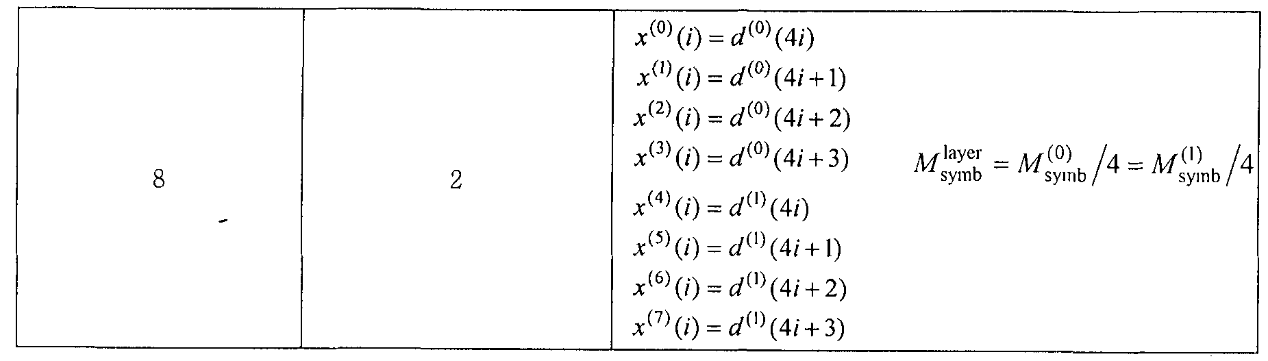
- data may be composed of a plurality of codewords, and data constituting such codewords are mapped to a plurality of layers as shown in Table 1.
- ⁇ s y mb —), where ⁇ * denotes the number of layers and ⁇ denotes the number of modulation symbols per layer. Also, the number of layers ⁇
- Is equal to or less than the number p of antenna ports.
- all time-frequency resources may not be transmitted in the same spatial resource, that is, the layer.
- FIG. 8 shows an example of mapping data to spatial resources using a multiplex antenna technique.
- data may not be transmitted in a specific layer of some time-frequency resources, but may be transmitted in all layers of the remaining time-frequency resources.
- the base station is a relay node, R-, which is a relay node specific control channel.
- the R—PDCCH transmits a control channel of rank 1 according to characteristics, that is, mapped to one layer, and data may be mapped to the remaining layers. Accordingly, data may not be transmitted due to R—PDCCH in a certain layer of some time_frequency resources, and data may be transmitted in all layers of time-frequency resources.
- the present invention proposes a layer mapping method when the number of data information mapped to a specific layer is different from the number of data mapped to another layer.
- mapping when data is mapped, mapping is performed in layer-frequency-time order, but when resources that are not available for data mapping exist in a specific layer, the mapping is continued in a layer-frequency-time order except for the corresponding layer. Suggest.
- layer-frequency-time mapping means that data is mapped to the layer axis, and if data is mapped to all layers, then the data is mapped to the layer axis after moving to the frequency resource, and then the frequency. It means mapping while moving to resources. Therefore, if all data is mapped to all the layer-frequency in the first OFDM symbol, the next shift to the OFDM symbol to apply the same mapping method. '
- FIG. 9 is a diagram illustrating a layer mapping method according to the first embodiment of the present invention.
- FIG. 9A illustrates a case where one codeword is mapped to two layers
- FIG. 9B illustrates a case where one codeword is mapped to three layers.
- An example of not allocated for data transmission is illustrated.
- the first embodiment of the present invention can be summarized as shown in Table 2 below.
- V 01 lay rx — 1 M (0) -V
- the left layer of Table 2 is mapped in frequency-time order, but when the layer that is a spatial resource for x (0) is not allocated, the right mapping method of Table 2 may be used. That is, if a layer that is a spatial resource for ⁇ 0) (is not allocated, it may continue to wrap in a layer-frequency-time order except for the corresponding layer.
- Increment j by 1, Increment i x by
- the mapping is sequentially performed in the direction of the layer-frequency ⁇ time order, but when there is a resource that is not available in a specific layer, the next logical time that can be transmitted from the position of the layer is mapped to the frequency resource.
- FIG. 10 is a diagram illustrating a layer mapping method according to a second embodiment of the present invention.
- FIG. 10A illustrates that one codeword is mapped to two layers.
- 10 (b) illustrates a case in which one codeword is mapped to three layers, and a specific resource of layer # 0 is not allocated for data transmission.
- FIG. 10 when data is mapped to two layers, data is preferentially mapped to a layer domain, and when data is mapped to all layers in a corresponding time—frequency resource, the layer is moved to the next frequency. Take turns mapping.
- the first layer maps to the next time-transmitted frequency resource, while the other layer enters the next time-frequency resource. Do the mapping, but always alternate between layers.
- data may be mapped in the order of layer-frequency-time in the remaining layers.
- the second embodiment of the present invention can be summarized as shown in Table 5 below.
- 11 is a diagram illustrating a layer mapping method according to a third embodiment of the present invention. 10 illustrates only a case where one codeword is mapped to two layers for convenience of description.
- the third embodiment of the present invention does not fill all of the layer domains recursively as in the second embodiment, but if there is a time-frequency resource that cannot transmit data in a specific layer.
- mapping to the specific layer If data is mapped, the next mapping must be mapped to the next layer. If there are no more inter-frequency resources that can be mapped in the specific layer, the mapping is continued in the same manner except for the corresponding layer. Suggest to do. ,
- each codeword when two or more codewords are transmitted. For example, if there is a time-frequency resource that is not allocated in a specific layer, and the codeword mapped to the layer is one of a plurality of codewords, the corresponding codeword is implemented in the method proposed by the present invention.
- Other codewords may utilize conventional data mapping methods.
- data is encoded and rate matched according to the total amount of resources that can be actually transmitted.
- data is encoded and rate matched to the amount of available resources, including some of the resources. can do. That is, assuming that all layers have the same number of time-frequency resources, the data may be encoded and rate matched to perform mapping under the assumption that some of the resources are also allocated for data transmission. That is, a method of not transmitting data mapped to a time-frequency resource of a specific layer may be considered. This method can reduce the implementation complexity without changing the layer mapping structure.
- the communication device 1200 includes a processor 1210, a memory 1220, RF modules 1230, display modules 1240 and user interface modules 1250.
- the communication device 1200 is shown for convenience of description and some models may be omitted.
- the communication device 1200 may further include the necessary modules.
- some modules in the communication device 1200 may be divided into more granular modules.
- the processor 1210 is configured to perform an operation according to the embodiment of the present invention illustrated with reference to the drawings. In detail, the detailed operation of the processor 1210 may refer to the contents described with reference to FIGS. 1 to 11.
- the memory 1220 is connected to the processor 1210 and stores an operating system, an application, a program code, data, and the like.
- the RF modules 1230 are connected to the processor 1210 and perform a function of converting a baseband signal into a radio signal or converting a radio signal into a baseband signal. To this end, the RF modules 1230 perform analog conversion, amplification, filtering and frequency up-conversion or their reverse processes.
- the display modules 1240 are connected to the processor 1210 and display various information.
- the display module 1240 may use well-known elements such as, but not limited to, a liquid crystal display (LCD), a light emitting diode (LED), and a zero light emitting diode (0LED).
- the user interface modules 1250 are connected to the processor 1210 and may be configured with a combination of well-known user interfaces such as a keypad, a touch screen, and the like.
- Certain operations described in this document as being performed by a base station may, in some cases, be performed by their upper node. That is, it is apparent that various operations performed for communication with the terminal in a network including a plurality of network nodes including a base station may be performed by the base station or other network nodes other than the base station.
- a base station may be replaced by terms such as a fixed station, a Node B, an eNode B (eNB), an access point, and the like.
- Embodiments according to the present invention may be implemented by various means, for example, hardware, firmware, software, or a combination thereof.
- an embodiment of the present invention may include one or more ASICs (applied cationic specific integrated circuits), digital signal processors (DSPs), digital signal processing devices (DSPDs), programmable PLDs logic devices), field programmable gate arrays (FPGAs), processors, controllers, microcontrollers, microprocessors, and the like.
- ASICs applied cationic specific integrated circuits
- DSPs digital signal processors
- DSPDs digital signal processing devices
- FPGAs field programmable gate arrays
- processors controllers, microcontrollers, microprocessors, and the like.
- firmware or software an embodiment of the present invention may be implemented in the form of modules, procedures, functions, etc. that perform the functions or operations described above.
- the software code may be stored in a memory unit and driven by a processor.
- the memory unit may be located inside or outside the processor, and may exchange
Landscapes
- Engineering & Computer Science (AREA)
- Signal Processing (AREA)
- Computer Networks & Wireless Communication (AREA)
- Mobile Radio Communication Systems (AREA)
- Transmitters (AREA)
Abstract
본 출원에서는 다중 안테나 무선 통신 시스템에서 송신단이 수신단으로 데이터를 송신하는 방법이 개시된다. 구체적으로, 상기 데이터를 위하여 할당된 송신 자원을 상기 데이터에 공간 도메인, 주파수 도메인 및 시간 도메인 순으로 맵핑하는 단계; 및 상기 맵핑된 송신 자원을 이용하여 상기 데이터를 상기 수신단으로 송신하는 단계를 포함하고, 상기 송신 자원은 복수의 공간 자원을 포함하고, 상기 복수의 공간 자원 각각은 특정 시간 자원과 특정 주파수 자원으로 정의되는 복수의 자원 할당 유닛으로 구성되며, 상기 맵핑하는 단계는 특정 공간 자원에 할당된 상기 자원 할당 유닛이 존재하지 않는 경우, 상기 복수의 복소 심볼은 나머지 공간 자원에 주파수 자원 및 시간 자원 순으로 맹핑하는 단계를 포함하는 것을 특징으로 한다.
Description
【명세서】
【발명의 명칭】
다중 안테나 무선 통신 시스템에서 데이터를 송신하는 방법 및 이를 위한 장치
【기술분야】
본 발명은 무선 통신 시스템에 관한 것으로서, 보다 상세하게는, 다중 안테나 무선 통신 시스템에서 데이터를 송신하는 방법 및 이를 위한 장치에 관한 것이다.
【배경기술】
본 발명이 적용될 수 있는 무선 통신 시스템의 일례로서 3GPP LTE (3rd
Generation Partnership Project Long Term Evolution; 이하 "LTE"라 함) 통신 시스템에 대해 개략적으로 설명한다. .
도 1은 무선 통신 시스템의 일례로서 E— UMTS 망구조를 개략적으로 도시한 도면이다. E-U TSC Evolved Universal Mobile Telecommunications System) 시스템은 기존 UMTS Jniversal Mobile Telecommunications System)에서 진화한 시스템으로서, 현재 3GPP에서 기초적인 표준화 작업을 진행하고 있다. 일반적으로 E-UMTS는 LTE(Long Term Evolution) 시스템이라고 할 수도 있다. UMTS 및 E-UMTS의 기술 규격 (technical specification)^ 상세한 내용은 각각 "3rd Generation Partnership Project; Technical Specification Group Radio Access Network"의 Release 7과 Release 8을 참조할 수 있다.
도 1을 참조하면, E-UMTS는 단말 (User Equipment; UE)과 기지국 (eNode B;
eNB, 네트워크 (E-UTRAN)의 종단에 위치하여 외부 네트워크와 연결되는 접속 게이트웨이 (Access Gateway; AG)를 포함한다. 기지국은 브로드캐스트 서비스, 멀티캐스트 서비스 및 /또는 유니캐스트 서비스를 위해 다중 데이터 스트림을 동시에 전송할수 있다.
한 기지국에는 하나 이상의 셀이 존재한다. 셀은 1.25, 2.5, 5, 10, 15,
20Mhz 등의 대역폭 중 하나로 설정돼 여러 단말에게 하향 또는 상향 전송 서비스를 제공한다. 서로 다른 셀은 서로 다른 대역폭을 제공하도톡 설정될 수 있다. 기지국은 다수의 단말에 대한 데이터 송수신을 제어한다. 하향 링크 (Downlink; DL) 데이터에 대해 기지국은 하향 링크 스케즐링 정보를 전송하여 해당 단말에게 데이터가 전송될 시간-주파수 자원, 부호화, 데이터 크기, HARQ(Hybrid Automatic Repeat and reQuest) 관련 정보 등을 알려준다. 또한, 상향 링크 (Uplink; UL) 데이터에 대해 기지국은 상향 링크 스케줄링 정보를 해당 단말에게 전송하여 해당 단말이 사용할 수 있는 시간-주파수 자원, 부호화, 데이터 크기, HARQ 관련 정보 등을 알려준다. 기지국간에는 사용자 트래픽 또는 제어 트래픽 전송을 위한 인터페이스가 사용될 수 있다. 핵심망 (Core Network; CN)은 AG와 단말의 사용자 등록 등을 위한 네트워크 노드 등으로 구성될 수 있다. AG는 복수의 샐들로 구성되는 TA Yacking Area) 단위로 단말의 이동성을 관리한다.
무선 통신 기술은 WCDMA를 기반으로 LTE까지 개발되어 왔지만, 사용자와 사업자의 요구와 기대는 지속적으로 증가하고 있다. 또한, 다른 무선 접속 기술이 계속 개발되고 있으므로 향후 경쟁력을 가지기 위해서는 새로운 기술 진화가 요구된다. 비트당 비용 감소, 서비스 가용성 증대, 융통성 있는 주파수 밴드의
사용, 단순구조와 개방형 인터페이스, 단말의 적절한 파워 소모 등이 요구된다. 【발명의 상세한 설명】
【기술적 과제】
상술한 바와 같은 논의를 바탕으로 이하에서는 다중 안테나 무선 통신 시스템에서 데이터를 송신하는 방법 및 이를 위한 장치를 제안하고자 한다.
【기술적 해결방법】
본 발명의 일 실시예인 다중 안테나 무선 통신 시스템에서 송신단이 수신단으로 데이터를 송신하는 방법은, 상기 데이터를 위하여 할당된 송신 자원을 상기 데이터에 공간 도메인, 주파수 도메인 및 시간 도메인 순으로 맵핑하는 단계; 및 상기 맵핑된 송신 자원을 이용하여 상기 데이터를 상기 수신단으로 송신하는 단계를 포함하고, 상기 송신 자원은 복수의 공간 자원을 포함하고, 상기 복수의 공간 자원 각각은 특정 시간 자원과 특정 주파수 자원으로 정의되는 복수의 자원 할당 유닛으로 구성되며, 상기 맵핑하는 단계는 특정 공간 자원에 할당된 상기 자원 할당 유닛이 존재하지 않는 경우, 상기 복수의 복소 심볼은 나머지 공간 자원에 주파수 자원 및 시간 자원 순으로 맵핑하는 단계를 포함하는 것을 특징으로 한다.
여기서, 상기 자원 할당 유닛은 복소 변조 심볼 (Complexᅳ valued modulation symbol)이며, 상기 데이터는 1개의 코드워드로서 복소 변조 심볼 (Complex-valued modulation symbol) 단위로 부호화된 것을 특징으로 한다. 이와 같은 경우, 상기 방법은 상기 코드워드를 상기 송신 자원에 포함된 자원 할당 유닛의 개수에 맞추어 레이트 매칭하는 단계를 더 포함할 수 있다.
바람직하게는, 상기 복수의 공간 자원은 복수의 레이어 (layer)를 포함하는 것을 특징으로 한다.
보다 바람직하게는, 상기 특정 공간 자원에 존재하지 않는 상기 자원 할당 유닛은 제어 정보를 위하여 할당된 송신 자원인 것을 특징으로 한다.
한편, 본 발명의 다른 실시예로서 다중 안테나 무선 통신 시스템에서의 송신 장치는, 데이터를 위하여 할당된 송신 자원을 상기 데이터에 공간 도메인, 주파수 도메인 및 시간 도메인 순으로 맵핑하기 위한 프로세서; 및 상기 맵핑된 송신 자원을 이용하여 상기 데이터를 수신단으로 송신하기 위한 송신 모들을 포함하고, 상기 송신 자원은 복수의 공간 자원을 포함하고, 상기 복수의 공간 자원 각각은 특정 시간 자원과 특정 주파수 자원으로 정의되는 복수의 자원 할당 유닛으로 구성되며, 상기 프로세서는 특정 공간 자원에 할당된 상기 자원 할당 유닛이 존재하지 않는 경우, 상기 복수의 복소 심볼은 나머지 공간 자원에 주파수 자원 및 시간 자원 순으로 템핑하는 것을 특징으로 한다.
【유리한 효과】
본 발명의 실시예에 따르면 다증 안테나 무선 통신 시스템에서 송신단은 수신단으로 데이터를 보다 효과적으로 전송할 수 있다.
본 발명에서 얻을 수 있는 효과는 이상에서 언급한 효과들로 제한되지 않으며, 언급하지 않은 또 다른 효과들은 아래의 기재로부터 본 발명이 속하는 기술분야에서 통상의 지식을 가진 자에게 명확하게 이해될 수 있을 것이다.
【도면의 간단한 설명】
. 도 1은 무선 통신 시스템의 일례로서 Eᅳ UMTS 망구조를 개략적으로 도시한
도면이다.
도 2는 3GPP 무선 접속망 규격을 기반으로 한 단말과 E-UTRAN 사이의 무선 인터페이스 프로토콜 (Radio Interface Protocol)의 제어평면 (Control Plane) 및 사용자평면 (User Plane) 구조를 나타내는 도면이다.
도 3은 3GPP 시스템에 이용되는 물리 채널들 및 이들을 이용한 일반적인 신호 전송 방법을 설명하기 위한 도면이다.
도 4는 LTE 시스템에서 사용되는 무선 프레임의 구조를 예시하는 도면이다. 도 5는 LTE 시스템에서 사용되는 하향 링크 무선 프레임의 구조를 예시하는 도면이디-.
도 6은 LTE 시스템에서 사용되는 상향 링크 서브프레임의 구조를 도시하는 도면이다.
도 7은 일반적인 다중 안테나 (MIM0) 통신 시스템의 구성도이다.
도 8은 다중 안테나 기법을 사용하여 데이터를 공간 자원에 맵핑한 예를 도시한다.
. 도 9는 본 발명의 제 1 실시예에 따른 레이어 맵핑 방법을 예시하는 도면이다.
도 10은 본 발명의 제 2 실시예에 따른 레이어 맵핑 방법을 예시하는 도면이다.
도 11은 본 발명의 제 3 실시예에 따른 레이어 맵큉 방법을 예시하는 도면이다.
도 12는 본 발명의 일 실시예에 따른 통신 장치의 블록 구성도를 예시한다.
【발명의 실시를 위한 형태】
이하에서 첨부된 도면을 참조하여 설명된 본 발명의 실시예들에 의해 본 발명의 구성, 작용 및 다른 특징들이 용이하게 이해될 수 있을 것이다. 이하에서 설명되는 실시예들은 본 발명의 기술적 특징들이 3GPP 시스템에 적용된 예들이다ᅳ 본 명세서는 LTE 시스템 및 LTE-A 시스템을 사용하여 본 발명의 실시예를 설명하지만, 이는 예시로서 본 발명의 실시예는 상기 정의에 해당되는 어떤 통신 시스템에도 적용될 수 있다ᅳ 또한, 본 명세서는 FDD 방식을 기준으로 본 발명의 실시예에 대해 설명하지만, 이는 예시로서 본 발명의 실시예는 H-FDD 방식 또는 TDD 방식에도 용이하게 변형되어 적용될 수 있다.
도 2는 3GPP 무선 접속망 규격을 기반으로 한 단말과 E— UTRAN 사이의 무선 인터페이스 프로토콜 (Radio Interface Protocol)의 제어평면 (Control Plane) 및 사용자평면 (User Plane) 구조를 나타내는 도면이다. 제어평면은 단말 (User Equipment; UE)과 네트워크가 호를 관리하기 위해서 이용하는 제어 메시지들이 전송되는 통로를 의미한다. 사용자평면은 애플리케이션 계층에서 생성된 데이터, 예를 들어, 음성 데이터 또는 인터넷 패킷 데이터 등이 전송되는 통로를 의미한다. 제 1계층인 물리계층은 물리채널 (Physical Channel)을 이용하여 상위 계충에게 정보 전송 서비스 (Information Transfer Service)를 제공한다. 물리계충은 상위에 있는 매체접속제어 (Medium Access Control) 계층과는 전송채널 (Transport Channel)을 통해 연결되어 있다. 상기 전송채널을 통해 매체접속제어 계층과 물리계층 사이에 데이터가 이동한다. 송신측과 수신측의 물리계충 사이는 물리채널을 통해 데이터가 이동한다. 상기 물리채널은 시간과
주파수를 무선 자원으로 활용한다. 구체적으로, 물리채널은 하향 링크에서
0FDMA( Orthogonal Frequency Division Multiple Access) 방식으로 변조되고, 상향 링크에서 SC-FDMA( Single Carrier Frequency Division Multiple Access) 방식으로 변조된다.
게 2계층의 매체접속제어 (Medium Access Control; MAC) 계층은 논리채널 (Logical Channel)을 통해 상위계층인 무선링크제어 (Radio Link Control; RLC) 계충에 서비스를 제공한다. 게 2계층의 RLC 계층은 신뢰성 있는 데이터 전송을 지원한다. RLC 계층의 기능은 MAC 내부의 기능 블록으로 구현될 수도 있다.제 2계층의 PDCP(Packet Data Convergence Protocol) 계층은 대역폭이 좁은 무선 인터페이스에서 IPv4나 IPv6와 같은 IP 패킷을 효율적으로 전송하기 위해 불필요한 제어정보를 줄여주는 헤더 압축 (Header Compression) 기능을 수행한다. 제 3계층의 최하부에 위치한 무선 자원제어 (Radio Resource Control; RRC) 계층은 제어평면에서만 정의된다. C 계층은 무선베어러 (Radio Bearer; RB)들의 설정 (Configuration), 재설정 (Re-conf igurat ion) 및 해게 (Release)와 관련되어 논리채널, 전송채널 및 물리채널들의 제어를 담당한다. RB는 단말과 네트워크 간의 데이터 전달을 위해 제 2계층에 의해 제공되는 서비스를 의미한다. 이를 위해, 단말과 네트워크의 RRC 계층은 서로 R C 메시지를 교환한다. 단말과 네트워크의 RRC 계층 사이에 RRC 연결 (RRC Connected)이 있을 경우, 단말은 RRC 연결 상태 (Connected Mode)에 있게 되고, 그렇지 못할 경우 RRC 휴지 상태 (Idle Mode)에 있게 된다. RRC 계층의 상위에 있는 NAS(Non— Access Stratum) 계층은 세션 관리 (Session Management)와 이동성 관리 (Mobility Management ) 등의 기능을
수행한다 .
기지국 (eNB)을 구성하는 하나의 샐은 1.25, 2.5, 5, 10, 15, 20Mhz '등의 대역폭 중 하나로 설정되어 여러 단말에게 하향 또는 상향 전송 서비스를 제공한다. 서로 다른 셀은 서로 다른 대역폭을 제공하도록 설정될 수 있다.
네트워크에서 단말로 데이터를 전송하는 하향 전송채널은 시스템 정보를 전송하는 BCH(Broadcast Channel), 페이징 메시지를 전송하는 PCH( Paging Channel), 사용자 트래픽이나 제어 메시지를 전송하는 하향 SCH(Shared Channel) 등이 있다. 하향 멀티캐스트 또는 방송 서비스의 트래픽 또는 제어 메시지의 경우 하향 SCH를 통해 전송될 수도 있고, 또는 별도의 하향 MOKMult icast Channel)을 통해 전송될 수도 있다. 한편, 단말에서 네트워크로 데이터를 전송하는 상향 전송채널로는 초기 제어 메시지를 전송하는 RACH(Random Access Channel), 사용자 트래픽이나 제어 메시지를 전송하는 상향 SCH(Shared Channel)가 있다. 전송채널의 상위에 있으몌 전송채널에 매핑되는 논리채널 (Logical Channel)로는 BCCH(Broadcast Control Channel), PCCH( Paging Control Channel), CCCH( Common Control Channel), MCCH(Mult icast Control Channel), MTCH(Mult icast Traffic Channel) 등이 있디-. 도 3은 3GPP 시스템에 이용되는 물리 채널들 및 이들을 이용한 일반적인 신호 전송 방법을 설명하기 위한 도면이다.
단말은 전원이 켜지거나 새로이 셀에 진입한 경우 기지국과 동기를 맞추는 등의 초기 셀 탐색 (Initial cell search) 작업을 수행한다 (S301). 이를 위해, 단말은 기지국으로부터 주 동기 채널 (Primary Synchronization Channel; P-SCH) 및 부 동기 채널 (Secondary Synchronization Channel; S-SCH)을 수신하여 기지국과
동기를 맞추고, 셀 ID 등의 정보를 획득할 수 있다. 그 후, 단말은 기지국으로부터 물리 방송 채널 (Physical Broadcast Channel)를 수신하여 셀 내 방송 정보를 획득할 수 있다. 한편, 단말은 초기 셀 탐색 단계에서 하향 링크 참조 신호 (Downlink Reference Signal; DL RS)를 수신하여 하향 링크 채널 상태를 확인할 수 있다.
초기 샐 탐색을 마친 단말은 물리 하향 링크 제어 채널 (Physical Downlink Control Channel; PDCCH) 및 상기 PDCCH에 실린 정보에 따라 물리 하향 링크 공유 채널 (Physical Downlink Control Channel; PDSCH)을 수신함으로써 좀더 구체적인 시스템 정보를 획득할 수 있다 (S302).
한편, 기지국에 최초로 접속하거나 신호 전송을 위한 무선 자원이 없는 경우 단말은 기지국에 대해 임의 접속 과정 (Random Access Procedure; RACH)을 수행할 수 있다 (단계 S303 내지 단계 S306). 이를 위해 단말은 물리 임의 접속 채널 (Physical Random Access Channel; PRACH)을 통해 특정 사퀀스를 프리앰블로 전송하고 (S303 및 S305), PDCCH 및 대웅하는 PDSCH를 통해 프리앰블에 대한 응답 메시지를 수신할 수 있다 (S304 및 S306). 경쟁 기반 RACH의 경우, 추가적으로 충돌 해결 절차 (Contention Resolution Procedure)를 수행할 수 있다.
상술한 바와 같은 절차를 수행한 단말은 이후 일반적인 상 /하향 링크 신호 전송 절차로서 PDCCH/PDSCH 수신 (S307) 및 물리 상향 링크 공유 채널 (Physical Uplink Shared Channel; PUSCH)/물리 상향 링크 제어 채널 (Physical Uplink Control Channel; PUCCH) 전송 (S308)을 수행할 수 있다. 특히 단말은 PDCCH를 통하여 하향링크 제어 정보 (Downlink Control Information; DCI)를 수신한다.
여기서 DCI는 단말에 대한 자원 할당 정보와 같은 제어 정보를 포함하며, 그 사용 목적에 따라 포맷이 서로 다르다.
한편, 단말이 상향 링크를 통해 기지국에 전송하는 또는 단말이 기지국으로부터 수신하는 제어 정보는 하향 링크 /상향 링크 ACK/NACK 신호, CQI (Channel Quality Indicator) , ΡΜΙ (Precoding Matrix Index) , RK ank Indicator) 등을 포함한다/ 3GPP LTE 시스템의 경우, 단말은 상술한 CQI/PMI/RI 등의 제어 정보를 PUSCH 및 /또는 PUCCH를 통해 전송할 수 있다.
■ 도 4는 LTE 시스템에서 사용되는 무선 프레임의 구조를 예시하는 도면이다. 도 4를 참조하면, 무선 프레임 (radio frame)은 10ms (327200 XTS)의 길이를 가지며 10개의 균등한 크기의 서브프레임 (subframe)으로 구성되어 있다. 각각의 서브프레임은 1ms의 길이를 가지며 2개의 슬롯 (slot)으로 구성되어 있다. 각각의 슬롯은 0.¾113(15360>< )의 길이를 가진다. 여기에서, Ts 는 샘플링 시간을 나타내고, Ts=l/(15kHzX2048)=3.2552xi0— 8(약 33ns)로 표시된다. 슬롯은 시간 영역에서 복수의 0FDM 심볼을 포함하고, 주파수 영역에서 복수의 자원블록 (Resource Block; RB)을 포함한다. LTE 시스템에서 하나의 자원블록은 12개의 부반송파 X7(6)개의 0FDM 심볼을 포함한다. 데이터가 전송되는 단위시간인 ΓΓΙ (Transmission Time Interval)는 하나 이상의 서브프레임 단위로 정해질 수 있다. 상술한 무선 프레임의 구조는 예시에 불과하고, 무선 프레임에 포함되는 서브프레임의 수 또는 서브프레임에 포함되는 슬롯의 수, 슬롯에 포함되는 0FDM 심볼의 수는 다양하게 변경될 수 있다.
도 5는 하향 링크 무선 프레임에서 하나의 서브프레임의 제어 영역에.
포함되는 제어 채널을 예시하는 도면이다.
도 5를 참조하면, 서브프레임은 14개의 OFDM 심볼로 구성되어 있다. 서브프레임 설정에 따라 처음 1 내지 3개의 OFDM 심볼은 제어 영역으로 사용되고 나머지 13~11개의 OFDM 심볼은 데이터 영역으로 사용된다. 도면에서 R1 내지 R4는 안테나 0 내지 3에 대한 기준 신호 (Reference Signal (RS) 또는 Pilot Signal)를 나타낸디-. RS는 제어 영역 및 데이터 영역과 상관없이 서브프레임 내에 일정한 패턴으로 고정된다. 제어 채널은 제어 영역 중에서 RS가 할당되지 않은 자원에 할당되고, 트래픽 채널도 데이터 영역 중에서 RS가 할당되지 않은 자원에 할당된다. 제어 영역에 할당되는 제어 채널로는 PCFIOKPhysical Control Format. Indicator CHa皿 el), PHICH(Physical ' Hybrid— ARQ Indicator CHannel), PDCCH( Physical Downlink Control CHannel) 등이 있다.
PCFICH는 물리 제어 포맷 지시자 채널로서 매 서브프레임 마다 PDCCH에 사용되는 OFDM 심볼의 개수를 단말에게 알려준다. PCFICH는 첫 번째 OFDM 심볼에 위치하며 PHICH 및 PDCCH에 우선하여 설정된다. PCFICH는 4개의 REG(Resource Element Group)로 구성되고, 각각의 REG는 셀 ID Cell IDentity)에 기초하여 제어 영역 내에 분산된다. 하나의 REG는 4개의 RE(Resource Element)로 구성된다. RE는 하나의 부반송파 X하나의 OFDM 심볼로 정의되는 최소 물리 자원을 나타낸다. PCFICH 값은 대역폭에 따라 1 내지 3 또는 2 내지 4의 값을 지시하며 QPSK( Quadrat Lire Phase Shift Keying)로 변조된다.
PHICH는 물리 HARQ(Hybrid ᅳ Automatic Repeat and request) 지시자 채널로서 상향 링크 전송에 대한 HARQ ACK/NACK을 나르는데 사용된다. 즉, PHICH는
UL HARQ를 위한 DL ACK/NACK 정보가 전송되는 채널을 나타낸다. PHICH는 1개의
REG로 구성되고, 셀 특정 (cell-specific)하게 스크램블 (scrambl ing) 된다.
ACK/NACK은 1 비트로 지시되며, BPSK(Binary phase shift keying)로 변조된다. 변조된 ACK/NACK은 확산인자 (Spreading Factor;ᅳ SF) = 2 또는 4로 확산된다. 동일한 자원에 매핑되는 복수의 PHICH는 PHICH 그룹을 구성한다. PHICH 그룹에 다중화되는 PHICH의 개수는 확산 코드의 개수에 따라 결정된다. PHICH (그룹)은 주파수 영역 및 /또는 시간 영역에서 다이버시티 이득을 얻기 위해 3번 반복 (repetition)된다.
PDCCH는 물리 하향 링크 제어 채널로서 서브프레임의 처음 n개의 OFDM 심볼에 할당된다. 여기에서, n은 1 이상의 정수로서 PCFICH에 의해 지시된다. -
PDCCH는 하나 이상의 CCE로 구성된다. PDCCH는 전송 채널인 PCH(Paging channel) 및 DL—SCH(Downl ink-shared channel)의 자원할당과 관련된 정보, 상향 링크 스케줄링 그랜트 (Uplink Scheduling Grant), HARQ 정보 등을 각 단말 또는 단말. 그룹에게 알려준다. PCH(Paging channel) 및 DL-SCH(Downl ink-shared channel)는 PDSCH를 통해 전송된다. 따라서, 기지국과 단말은 일반적으로 특정한 제어 정보 또는 특정한 서비스 데이터를 제외하고는 PDSCH를 통해서 데이터를 각각 전송 및 수신한다.
PDSCH의 데이터가 어떤 단말 (하나 또는 복수의 단말)에게 전송되는 것이며, 상기 단말들이 어떻게 PDSCH 데이터를 수신하고 디코딩 (decoding)을 해야 하는 지에 대한 정보 등은 PDCCH에 포함되어 전송된다. 예를 들어, 특정 PDCCH가 라는 RNTI (Radio Network Temporary Identity)로 CRC 마스킹 (masking)되어 있고,
"Β' '라는 무선자원 (예, 주파수 위치) 및 라는 DCI 포맷 즉, 전송형식정보 (예, 전송 블록 사이즈, 변조 방식, 코딩 정보 등)를 이용해 전송되는 데이터에 관한 정보가 특정 서브프레임을 통해 전송된다고 가정한다. 이 경우, 셀 내의 단말은 자신이 가지고 있는 RNTI 정보를 이용하여 PDCCH를 모니터링하고, "A" RNTI를 가지고 있는 하나 이상의 단말이 있다면, 상기 단말들은 PDCCH를 수신하고, 수신한 PDCCH의 정보를 통해 "B"와 "C"에 의해 지시되는 PDSCH를 수신한다.
도 6은 LTE 시스템에서 사용되는 상향 링크 서브프레임의 구조를 도시하는 도면이디-.
도 6을 참조하면, 상향 링크 서브프레임은 제어정보를 나르는 PUCCH(Physical Uplink Control CHannel)가 할당되는 영역과 사용자 데이터를 나르는 PUSCH(Physical Uplink Shared CHannel)가 할당되는 영역으로 나눌 수 있다. 서브프레임의 중간 부분이 PUSCH에 할당되고, 주파수 영역에서 데이터 영역의 양측 부분이 PUCCH에 할당된다. PUCCH 상에 전송되는 제어정보는 HARQ에 사용되는 AC /NACK, 하향 링크 채널 상태를 나타내는 CQI (Channel Quality Indicator), MIMO를 위한 RI(Rank Indicator), 상향 링크 자원 할당 요청인 SR(Schedul ing Request) 등이 있다. 한 단말에 대한 PUCCH는 서브프레임 내의 각 슬롯에서 서로 다른 주파수를 차지하는 하나의 자원블록을 사용한다. 즉, PUCCH에 할당되는 2개의 자원블록은 슬롯 경계에서 주파수 호핑 (frequency hopping)된다. 특히 도 6은 m=0인 PUCCH, m=l인 PUCCH, m=2인 PUCCH, m=3인 PUCCH가 서브프레임에 할당되는 것을 예시한다.
이하 MIM0 시스템에 대하여 설명한다. MIMO(Multiple-Input Multiple-
Output)는 복수개의 송신안테나와 복수개의 수신안테나를 사용하는 방법으로서., 이 방법에 의해 데이터의 송수신 효율을 향상시킬 수 있다. 즉, 무선 통신 시스템의 송신단 혹은 수신단에서 복수개의 안테나를 사용함으로써 용량을 증대시키고 성능을 향상 시킬 수 있다. 이하 본 문헌에서 MIM0를 '다중 안테나 '라 지칭할 수 있다.
다중 안테나 기술에서는, 하나의 전체 메시지를 수신하기 위해 단일 안테나 경로에 의존하지 않는다. 그 대신 다중 안테나 기술에서는 여러 안테나에서 수신된 데이터 조각 (fragment)을 한데 모아 병합함으로써 데이터를 완성한다. 다증 안테니- 기술을 사용하면, 특정된 크기의 셀 영역 내에서 데이터 전송 속도를 향상시키거나., 또는 특정 데이터 전송 속도를 보장하면서 시스템 커버리지 (coverage)를 증가시킬 수 있다. 또한, 이 기술은 이동통신 단말과 중계기 등에 폭넓게 사용할 수 있다. 다중 안테나 기술에 의하면, 단일 안테나를 사용하던 종래 기술에 의한 이동 통신에서의 전송량 한계를 극복할 수 있다.
일반적인 다중 안테나 (MIM0) 통신 시스템의 구성도가 도 7에 도시되어 있다. 송신단에는 송신 안테나가 Ντ개 설치되어 있고, 수신단에서는 수신 안테나가 NR개가 설치되어 있다. 이렇게 송신단 및 수신단에서 모두 복수개의 안테나를 사용하는 경우에는, 송신단 또는 수신단 중 어느 하나에만 복수개의 안테나를 사용하는 경우보다 이론적인 채널 전송 용량이 증가한다. 채널 전송 용량의 증가는 안테나의 수에 비례한다. 따라서, 전송 레이트가 향상되고, 주파수 효율이 향상된다 하나의 안테나를 이용하는 경우의 최대 전송 레이트를 R0라고 한다면, 다증 안테나를 사용할 때의 전송 레이'트는, 이론적으로, 아래 수학식 1과 같이
최대 전송 레이트 R0에 레이트 증가율 Ri를 끕한 만큼 증가할 수 있다. 여기서 Ri는 Ντ와 NR 중 작은 값이다.
【수학식 11
R^mm{NT,NR)
예를 들어, 4개의 송신 안테나와 4개의 수신 안테나를 이용하는 MIM0 통신 시스템에서는, 단일 안테나 시스템에 비해 이론상 4배의 전송 레이트를 획득할 수 있다. 이와 같은 다중 안테나 시스템의 이론적 용량 증가가 90 년대 중반에 증명된 이후, 실질적으로 데이터 전송률을 향상시키기 위한 다양한 기술들이 현재까지 활발히 연구되고 있으며, 이들 중 몇몇 기술들은 이미 3 세대 이동 통신과 차세대 무선랜 등의 다양한 무선 통신의 표준에 반영되고 있다.
현재까지의 다중안테나 관련 연구 동향을 살펴보면 다양한 채널 환경 및 다중접속 환경에서의 다중안테나 통신 용량 계산 등과 관련된 정보 이론 측면 연구, 다중안테나 시스템의 무선 채널 측정 및 모형 도출 연구, 그리고 전송 신뢰도 향상 및 전송률 향상을 위한 시공간 신호 처리 기술 연구 등 다양한 관점에서 활발한 연구가 진행되고 있다.
다중 안테나 시스템에 있어서의 통신 방법을 보다 구체적인 방법으로 설명하기 위해 이를 수학적으로 모델링 하는 경우 다음과 같이 나타낼 수 있다. 도 7에 도시된 바와 같이 Ντ개의 송신 안테나와 NR개의 수신 안테나가 존재하는 것을 가정한다. 먼저, 송신 신호에 대해 살펴보면, Ντ개의 송신 안테나가 있는 경우 최대 전송 가능한 정보는 Ντ개이므로, 전송 정보를 하기의 수학식 2와 같은 백터로 나타낼 수 있다.
【수학식 2】

s Ν,
한편, 각각의 전송 정보 τ에 있어 전송 전력을 다르게 할 수 있으며, 이때 각각의 전송 전력을 ^라 하면, 전송 전력이 조정된 전송 정보를 백터로 나타내면 하기의 수학식 3과 같다.
【수학식 3】
S Ν. PlsliP2s2, - · · ,ΡΝ γ s Νγ 또한, 를 전송 전력의 대각행렬 Ρ를 이용하여 나타내면 하기의 수학식
4와 같다.
【수학식 4】

τ가 구성되는 경우를 고려해 보자. 여기서, 가중치 행렬은 전송 정보를 전송 채널 상황 등에 따라 각
안테나에 적절히 분배해 주는 ' 역할을 수행한다. 이와 같은 전송신호
V
"^2''"''^ 는 백터 를 이용하여 하기의 수학식 5와 같이 나타낼 수 있다. 여기서 ^ ^는 z'번째 송신안테나와 번째 정보 간의 가중치를 의미한다. w는 가중치 행렬 (Weight Matrix) 또는 프리코딩 행렬 (Precoding Matrix)이라고 불린다. 【수학식 5】

일반적으로, 채널 행렬의 랭크의 · 물리적인 의미는, 주어진 채널에서 서로 다른 정보를 보낼 수 있는 최대 수라고 할 수 있다. 따라서 채널 행렬의 랭크 (rank)는 서로 독립인 (independent) 행 (row) 또는 열 (column)의 개수 중에서 최소 개수로 정의되므로, 행렬의 랭크는 행 (row) 또는 열 (column)의 개수보다 클 수 없게 된다. 수식적으호 예를 들면, 채널 행렬 H의 탱크 (rank(H))는 수학식 6과 같이 제한된다.
【수학식 6】

또한, 다중 안테나 기술을 사용해서 보내는 서로 다른 정보 각각을 '전송
스트림 (Stream)' 또는 간단하게 1스트림' 으로 정의하기로 하자. 이와 같은 1스트림1 은 '레이어 (Layer)' 로 지칭될 수 있다. 그러면 전송 스트림의 개수는 당연히 서로 다른 정보를 보낼 수 있는 최대 수인 채널의 탱크 보다는 클 수 없게 된다. 따라서, 채널 행렬이 H는 아래 수학식 7과 같이 나타낼 수 있다.
【수학식 7]
# of streams < rank(n)≤ min(Vr, Nj
여기서 "# of st reams1'는 스트림의 수를 나타낸다. 한편, 여기서 한 개의 스트림은 한 개 이상의 안테나를 통해서 전송될 수 있음에 주의해야 한다.
한 개 이상의 스트림을 여러 개의 안테나에 대웅시키는 여러 가지 방법이 존재할 수 있다. 이 방법을 다중 안테나 기술의 종류에 따라 다음과 같이 설명할 ᄋ
수 있디-. 한 개의 스트림이 여러 안테나를 거쳐 전송되는 경丁 간 다이버시티 방식으로 볼 수 있고, 여러 스트림이 여러 안테나를 거쳐 전송되는 경우는 공간 멀티플렉싱 방식으로 볼 수 있다. 물론 그 중간인 공간 다이버시티와 공간 멀티플렉싱의 흔합 (Hybrid)된 형태도 가능하다.
LTE 시스템에서는 데이터는 복수개의 코드워드로 구성될 수 있으며 이러한 코드워드를 구성하는 데이터는 표 1과 같이 복수개의 레이어로 맵핑이 된다.

참고로, 아래 표 1에서 symb 코드워드 q의 복소 변조
-a (Com lex-valued modulation symbol)을 나타낸다 . 또한, 상기 복소 변조 심
 (단,
■ᅳ Π1 ¾ layer―■*
(단,
■ᅳ Π1 ¾ layer―■*
ί = symb— )와 같은 레이어로 맵핑이 되며, 여기서 ^*는 레이어의 개수를 ¬는 레이어 당 변조 심볼의 개수를 나타낸다. 또한, 상기 레이어의 개수 ^는
안테나 포트의 개수 p와 같거나 작다.
【표 1】

도 8은 다증 안테나 기법을 사용하여 데이터를 공간 자원에 맵핑한 예를 도시한다.
도 8을 참조하면, 데이터는 일부 시간-주파수 자원의 특정 레이어에서 전송되지 않고, 나머지 시간-주파수 자원의 모든 레이어에서 전송되는 것이 가능하다.
예를 들어, 기지국이 릴레이 노드로 릴레이 노드 특정 제어 채널인 R-
PDCCH를 송신하는 경우, 상기 R— PDCCH는 제어 채널을 특성 상 랭크 1의 전송, 즉 하나의 레이어에 맵핑되어 전송되며, 나머지 레이어들은 데이터가 맵핑될 수 있다. - 따라서, 일부 시간ᅳ주파수 자원의 특정 레이어에서는 R— PDCCH로 인하여 데이터가 전송되지 않고, 나머지 시간—주파수 자원의 모든 레이어에서는 데이터 전송이 가능할 수 있다.
그러나, 표 1과 같은 종래의 레이어 맵핑 방법을 사용을 하면, 특정 레이어에 맵핑되는 데이터 정보의 개수가 다른 레이어에 맵핑되는 데이터의 개수와.
다를 때에는 정상적으로 동작을 하지 않으며, 맵핑 방법이 문제가 된다. 따라서, 본 발명에서는 특정 레이어에 맵핑되는 데이터 정보의 개수가 다른 레이어에 맵핑되는 데이터의 개수와 다를 경우의 레이어 맵핑 방법을 제안한다.
<제 1 실시예 >
본 발명에서는 데이터가 맵핑될 때, 레이어-주파수 -시간 순으로 맵핑하되, 데이터 맵핑 시 사용 못하는 자원이 특정 레이어에 존재할 때에는 그 해당 레이어를 제외하고 레이어—주파수—시간 순의 방법으로 계속 맵핑하는 것을 제안한다.
여기서 레이어—주파수 -시간 순으로 맵핑이란, 레이어 축으로 데이터를 맵핑을 하고, 만약에 모든 레이어에 데이터가 맵핑이 되어 있다면, 그 다음 주파수 자원에 옮겨 레이어 축으로 또 데이터를 맵핑하고, 그 다음 주파수 자원으로 옮겨 가면서 맵핑하는 것을 의미한다. 따라서, 첫 OFDM 심볼에서 모든 레이어-주파수에 데이터를 모두 맵핑했다면, 그 다음 OFDM 심볼로 넘어가서 동일한 맵핑 방법을 적용하는 것이다. '
도 9는 본 발명의 제 1 실시예에 따른 레이어 맵핑 방법을 예시하는 도면이다.
특히, 도 9의 (a)는 2개의 레이어로 1개의 코드워드가 맵핑되는 경우이고, 9의 (b)는 3개의 레이어로 1개의 코드워드가 맵핑되는 경우로서, 레이어 #0의 특정 자원이 데이터 전송을 위하여 할당되지 않은 경우를 예시한다.
본 발명의 제 1 실시예는 아래 표 2와 같이 정리할 수 있다.
【표 2】
V =01 lay r x—1 M(0) -V ·뼤

상기 표 2를 참조하면, 일반적인 경우 표 2의 좌측 레이어—주파수 -시간 순으로 맵핑하되, x(0)( 를 위한 공간 자원인 레이어가 할당되지 않는 경우, 표 2의 우측 맵핑 방법을 이용할 수 있다. 즉, ^0)( 를 위한 공간 자원인 레이어가 할당되지 않는 경우, 그 해당 레이어를 제외하고 레이어-주파수 -시간 순의 방법으로 계속 맹핑할 수 있다.
본 발명의 제 1 실시예를 구현하는 다른 방법으로써 다음 표 3과 같은 수도 코드 알고리즘 (pseudo code algorithm)을 사용할 수 있다.
【표 3]
Set i to 0 Set j to 0
For x = 0 to L-l
If x(x)(i) is a valid data allocation
resource
-dm(j)
Increment j by 1
Else

End if
End for
Increment i by 1
End While
Prune out all values from x (i) which are set to <NULL>
또 다른 방법으로, 아래 표 4와 같은 수도 코드 알고리즘을 사용할 수 있다.
【표 4] to 0, Set j to 0

For x - 0 to L-l
If
 is a val id data al locat ion
resource
Increment j by 1, Increment ix by
1
End if
End for
End While
<제 2 실시예 >
본 발명의 제 2 실시예에서는 기본적으로 레이어-주파수ᅳ시간 순의 방향으로 순차적으로 맵핑을 하되, 사용 못하는 자원이 특정 레이어에 존재할 때에는 해당 레이어 입장에서 전송할 수 있는 그 다음 논리적 시간—주파수 자원에 맵핑을 하 방법을 제안한다. 즉, 각 레이어 별로 가용한 시간-주파수 자원을 배열하되, 배열 내에서 레이어-주파수—시간 순의 방향으로 순차적으로 맵핑하는 방법이다.
' 도 10은 본 발명의 제 2 실시예에 따른 레이어 맵핑 방법을 예시하 도면이다. 특히, 도 10의 (a)는 2개의 레이어로' 1개의 코드워드가 맵핑되는
경우이고, 10의 (b)는 3개의 레이어로 1개의 코드워드가 맵핑되는 경우로서ᅳ 레이어 #0의 특정 자원이 데이터 전송을 위하여 할당되지 않은 경우를 예시한다. 도 10을 참조하면 2개의 레이어에 데이터를 맵핑하는 경우, 레이어 도메인으로 우선적으로 데이터를 맵핑을 수행하고, 해당 시간—주파수 자원에서 모든 레이어에 데이터를 맵핑을 하였다면, 다음 주파수로 넘어가서 해당 레이어를 번갈아 가면서 맵핑을 수행한다.
만약 특정 시간-주파수 자원에서는 한 개의 레이어만 데이터를 전송할 수 있다면.ᅳ 첫 번째 레이어에서는 전송할 수 있는 그 다음 시간ᅳ주파수 자원에 맵핑을 하고, 다른 레이어에서는 그 해당 레이어 입장에서 다음 시간-주파수 자원에 맵핑을 하되, 항상 레이어를 번갈아 가며 맵핑을 수행한다.
또한, 더 이상 데이터 정보를 맵핑할 수 있는 특정 레이어가 없다면, 남은 레이어에서 레이어ᅳ주파수 -시간 순으로 데이터를 맵핑할 수 있다.
본 발명의 제 2 실시예는 아래 표 5와 같이 정리할 수 있다.
【표 5】

<제 3 실시예 >
도 11은 본 발명의 제 3 실시예에 따른 레이어 맵핑 방법을 예시하는 도면이다. 다만, 도 10은 설명의 편의를 위하여 1개의 코드워드가 2개의 레이어로 맵핑되는 경우만을 예시한다.
도 11을 참조하면, 본 발명의 제 3 실시예는, 제 2 실시예와 같이 순환적으로 레이어 도메인을 채울 수 있는 만큼 모두 채우는 것이 아니라, 특정 레이어에서 데이터를 보내지 못하는 시간-주파수 자원이 존재한다면 해당 시간- 주파수 자원에 위치하는 그 다음 레이어로 넘어가되, 상기 특정 레이어에 맵핑
데이터가 맵핑 되었다면, 반드시 다음 맵핑은 상기 다음 레이어에 맵핑을 하는 것을 원칙으로 하되, 만약 상기 특정 레이어에서 맵핑이 가능한 더 이상의 사간- 주파수 자원이 없다면, 그 해당 레이어를 제외하고 같은 방법으로 계속 맵핑을 하는 것을 제안한다. ,
한편, 상술한 실시예들은, 두 개 이상의 코드워드가 전송되는 경우에 각 코드워드 별로 적용할 수 있다. 예를 들어, 특정 레이어에서 할당되지 않은 시간- 주파수 자원이 있고, 이러한 레이어에 맵핑되는 코드워드가 복수개의 코드워드 중에서 한 개라면, 그 해당 코드워드를 본 발명에서 제안하고 있는 방법으로 구현을 하고, 다른 코드워드는 통상적인 데이터 맵핑 방법을 활용할 수 있다.
상술한 실시예들에서는 실제로 전송할 수 있는 총 자원의 양에 맞추어 데이터를 부호화 및 레이트 매칭 (rate matching)한 것으로 가정하였다. 그러니-, 상술한 실시예들과 같이 레이어 #0의 시간-주파수 자원 중 일부가 실제 데이터 전송을 위하여 할당되지 않았다고 할지라도, 상기 일부 자원을 포함하여 가능한 자원의 양에 맞추어 데이터를 부호화 및 레이트 매칭할 수 있다. 즉, 모든 레이어는 동일한 시간—주파수 자원 개수를 가지고 있다고 가정하고, 데이터를 부호화 및 레이트 매칭하여 상기 일부 자원 역시 데이터 전송을 위하여 할당되어 있다는 가정하에 맵핑을 수행할 수 있으며, 실제로 할당되지 않은 자원, 즉 특정 레이어의 시간—주파수 자원에 맵핑되어 있는 데이터는 전송하지 않는 방법도 고려할 수 있다. 이러한 방법은 레이어 맵핑 구조를 변경하지 않고, 구현 복잡도를 줄일 수 있는 효과가 있다.
도 12는 본 발명의 일 실시예에 따른 통신 장치의 블록 구성도를 예시한다.
도 12 를 참조하면 , 통신 장치 (1200)는 프로세서 (1210), 메모리 (1220), RF 모들 (1230), 디스플레이 모들 (1240) 및 사용자 인터페이스 모들 (1250)을 포함한다. 통신 장치 (1200)는 설명의 편의를 위해 도시된 것으로서 일부 모들은 생략될 수 있다. 또한, 통신 장치 (1200)는 필요한 모들을 더 포함할 수 있다. 또한, 통신 장치 (1200)에서 일부 모듈은 보다 세분화된 모들로 구분될 수 있다. 프로세서 (1210)는 도면을 참조하여 예시한 본 발명의 실시예에 따른 동작을 수행하도록 구성된다. 구체적으로, 프로세서 (1210)의 자세한 동작은 도 1 내지 도 11에 기재된 내용을 참조할 수 있다.
메모리 (1220)는 프로세서 (1210)에 연결되며 오퍼레이팅 시스템, 어플리케이션, 프로그램 코드, 데이터 등을 저장한다. RF 모들 (1230)은 프로세서 (1210)에 연결되며 기저대역 신호를 무선 신호를 변환하거나 무선신호를 기저대역 신호로 변환하는 기능을 수행한다. 이를 위해, RF 모들 (1230)은 아날로그 변환, 증폭, 필터링 및 주파수 상향 변환 또는 이들의 역과정을 수행한다. 디스플레이 모들 (1240)은 프로세서 (1210)에 연결되며 다양한 정보를 디스플레이한다. 디스플레이 모듈 (1240)은 이로 제한되는 것은 아니지만 LCD(Liquid Crystal Display), LED(Light Emitting Diode), 0LED(0rganic Light Emitting Diode)와 같은 잘 알려진 요소를 사용할 수 있다. 사용자 인터페이스 모들 (1250)은 프로세서 (1210)와 연결되며 키패드, 터치 스크린 등과 같은 잘 알려진 사용자 인터페이스의 조합으로 구성될 수 있다.
이상에서 설명된 실시예들은 본 발명의 구성요소들과 특징들이 소정 형태로 결합된 것들이다. 각 구성요소 또는 특징은 별도의 명시적 언급이 없는 한
선택적인 것으로 고려되어야 한다. 각 구성요소 또는 특징은 다른 구성요소나 특징과 결합되지 않은 형태로 실시될 수 있다. 또한, 일부 구성요소들 및 /또는 특징들을 결합하여 본 발명의 실시예를 구성하는 것도 가능하다. 본 발명의 실시예들에서 설명되는 동작들의 순서는 변경될 수 있다. 어느 실시예의 일부 구성이나 특징은 다른 실시예에 포함될 수 있고, 또는 다른 실시예의 대응하는 구성 또는 특징과 교체될 수 있다. 특허청구범위에서 명시적인 인용 관계가 있지 않은 청구항들을 결합하여 실시예를 구성하거나 출원 후의 보정에 의해 새로운 청구항으로 포함시킬 수 있음은 자명하다.
본 문서에서 기지국에 의해 수행된다고 설명된 특정 동작은 경우에 따라서는 그 상위 노드 (upper node)에 의해 수행될 수 있다. 즉, 기지국을 포함하는 복수의 네트워크 노드들 (network nodes)로 이루어지는 네트워크에서 단말과의 통신을 위해 수행되는 다양한 동작들은 기지국 또는 기지국 이외의 다른 네트워크 노드들에 의해 수행될 수 있음은 자명하다. 기지국은 고정국 (fixed station), Node B, eNode B(eNB), 억세스 포인트 (access point) 등의 용어에 의해 대체될 수 있다.
본 발명에 따른 실시예는 다양한 수단, 예를 들어, 하드웨어, 펌웨어 (fir隱 are), 소프트웨어 또는 그것들의 결합 등에 의해 구현될 수 있다. 하드웨어에 의한 구현의 경우, 본 발명의 일 실시예는 하나 또는 그 이상의 ASICs ( app 1 i cat ion specific integrated circuits) , DSPs(digi tal signal processors) , DSPDs(digi tal signal processing devices) , PLDs( programmable logic devices) , FPGAs (field programmable gate arrays) , 프로세서 , 콘트롤러 , 마이크로 콘트롤러, 마이크로 프로세서 등에 의해 구현될 수 있다.
펌웨어나 소프트웨어에 의한 구현의 경우, 본 발명의 일 실시예는 이상에서 설명된 기능 또는 동작들을 수행하는 모들, 절차, 함수 등의 형태로 구현될 수 있다. 소프트웨어 코드는 메모리 유닛에 저장되어 프로세서에 의해 구동될 수 있다. 상기 메모리 유닛은 상기 프로세서 내부 또는 외부에 위치하여, 이미 공지된 다양한 수단에 의해 상기 프로세서와 데이터를 주고 받을 수 있다.
본 발명은 본 발명의 특징을 벗어나지 않는 범위에서 다른 특정한 형태로 구체화될 수 있음은 당업자에게 자명하다. 따라서, 상기의 상세한 설명은 모든 면에서 제한적으로 해석되어서는 아니되고 예시적인 것으로 고려되어야 한다. 본 발명의 범위는 첨부된 청구항의 합리적 해석에 의해 결정되어야 하고, 본 발명의 등가적 범위 내에서의 모든 변경은 본 발명의 범위에 포함된다.
【산업상 이용가능성】
상술한 바와 같은 다중 안테나 무선 통신 시스템에서 신호를 송신하는 방법 및 이를 위한 장치는 3GPP LTE 시스템에 적용되는 예를 중심으로 설명하였으나, 3GPP LTE 시스템 이외에도 다양한 무선 통신 시스템에 적용하는 것이 가능하다.
Claims
【청구항 1】
다중 안테나 무선 통신 시스템에서 송신단이 수신단으로 데이터를 송신하는 방법에 있어서,
상기 데이터를 위하여 할당된 송신 자원을 상기 데이터에 공간 도메인, 주파수 도메인 및 시간 도메인 순으로 맵핑하는 단계 ; 및
상기 맵핑된 송신 자원을 이용하여 상기 데이터를 상기 수신단으로 송신하는 단계를 포함하고,
상기 송신 자원은 복수의 공간 자원을 포함하고ᅳ
상기 복수의 공간 자원 각각은 특정 시간 자원과 특정 주파수 자원으로 정의되는 복수의 자원 할당 유닛으로 구성되며,
상기 맵핑하는 단계는,
특정 공간 자원에 할당된 상기 자원 할당 유닛이 존재하지 않는 경우, 상기 복수의 복소 심볼은 나머지 공간 자원에 주파수 자원 및 시간 자원 순으로 ¾핑하는 단계를 포함하는 것을 특징으로 하는,
데이터 송신 방법. :
[청구항 2】
제 1 항에 있어서,
상기 자원 할당 유닛은,
복소 변조 심볼 (Comp lex- valued modulation symbol)인 것을 특징으로 하는, 것을 특징으로 하는,
데이터 송신 방법ᅳ
【청구항 3】
제 1 항에 있어서,
상기 데이터는
1개의 코드워드로서, 복소 변조 심볼 (Complex-valued modulation symbol) 단위로 부호화된 것을 특징으로 하는,
데이터 송신 방법.
【청구항 4]
제 1 항에 있어서,
상기 복수의 공간 자원은 복수의 레이어 (layer)를 포함하는 것을 특징으로 o卜 ΪΓ,
데이터 송신 방법.
【청구항 5】
제 3 항에 있어서,
상기 코드워드를 상기 송신 자원에 포함된 자원 할당 유닛의 개수에 맞추어 레이트 매칭하는 단계를 더 포함하는 것을 특징으로 하는,
데이터 송신 방법.
【청구항 6]
거 11 항에 있어서,
상기 특정 공간 자원에 존재하지 않는 상기 자원 할당 유닛은,
제어 정보를 위하여 할당된 송신 자원인 것을 특징으로 하는,
데이터 송신 방법.
【청구항 7]
다중 안테나 무선 통신 시스템에서의 송신 장치로서,
데이터를 위하여 할당된 송신 자원을 상기 데이터에 공간 도메인, 주파수 도메인 및 시간 도메인 순으로 맵핑하기 위한 프로세서; 및 .
상기 맵핑된 송신 자원을 이용하여 상기 데이터를 수신단으로 송신하기 위한 송신 모들을 포함하고,
상기 송신 자원은 복수의 공간 자원을 포함하고,
상기 복수의 공간 자원 각각은 특정 시간 자원과 특정 주파수 자원으로 정의되는 복수의 자원 할당 유닛으로 구성되며,
상기 프로세서는,
특정 공간 자원에 할당된 상기 자원 할당 유닛이 존재하지 않는 경우, 상기 복수의 복소 심볼은 나머지 공간 자원에 주파수 자원 및 시간 자원 순으로 맵핑하는 것을 특징으로 하는,
송신 장치 .
【청구항 8】
제 7 항에 있어서,
상기 자원 할당 유닛은,
복소 변조 심볼 (Complex— valued modulation symbol)인 것을 특징으로 하는, 것을 특징으로 하는,
송신 장치 .
【청구항 9】
제 7 항에 있어서 ,
상기 데이터는
1개의 코드워드로서, 복소 변조 심볼 (Comp lex- valued modulation symbol) 단위로 부호화된 것을 특징으로 하는,
송신 장치 .
【청구항 10]
제 7 항에 있어서,
상기 복수의 공간 자원은 복수의 레이어 (layer)를 포함하는 것을 특징으로 하는,
송신 장치 .
【청구항 11】
제 9 항에 있어서 ,
상기 프로세서는,
상기 코드워드를 상기 송신 자원에 포함된 자원 할당 유닛의 개수에 맞추어 레이트 매칭하는 것을 특징으로 하는,
송신 장치 .
【청구항 12】
제 7 항에 있어서,
상기 특정 공간 자원에 존재하지 않는 상기 자원 할당 유닛은,
• 제어 정보를 위하여 할당된 송신 자원인 것을 특징으로 하는,
송신 장치 .
Priority Applications (1)
| Application Number | Priority Date | Filing Date | Title |
|---|---|---|---|
| US14/116,211 US9136994B2 (en) | 2011-05-11 | 2012-04-19 | Method and device for transmitting data in a multi antenna wireless communication system |
Applications Claiming Priority (4)
| Application Number | Priority Date | Filing Date | Title |
|---|---|---|---|
| US201161485108P | 2011-05-11 | 2011-05-11 | |
| US61/485,108 | 2011-05-11 | ||
| US201161485128P | 2011-05-12 | 2011-05-12 | |
| US61/485,128 | 2011-05-12 |
Publications (2)
| Publication Number | Publication Date |
|---|---|
| WO2012153922A2 true WO2012153922A2 (ko) | 2012-11-15 |
| WO2012153922A3 WO2012153922A3 (ko) | 2013-01-03 |
Family
ID=47139764
Family Applications (1)
| Application Number | Title | Priority Date | Filing Date |
|---|---|---|---|
| PCT/KR2012/003004 WO2012153922A2 (ko) | 2011-05-11 | 2012-04-19 | 다중 안테나 무선 통신 시스템에서 데이터를 송신하는 방법 및 이를 위한 장치 |
Country Status (2)
| Country | Link |
|---|---|
| US (1) | US9136994B2 (ko) |
| WO (1) | WO2012153922A2 (ko) |
Families Citing this family (7)
| Publication number | Priority date | Publication date | Assignee | Title |
|---|---|---|---|---|
| US10524273B2 (en) | 2016-09-06 | 2019-12-31 | Telefonaktiebolaget Lm Ericsson (Publ) | Resource configuration of wireless devices |
| EP3510832B1 (en) * | 2016-09-06 | 2023-08-16 | Telefonaktiebolaget LM Ericsson (PUBL) | Resource configuration of wireless devices |
| WO2018048333A1 (en) | 2016-09-06 | 2018-03-15 | Telefonaktiebolaget Lm Ericsson (Publ) | Methods and devices for determination of beamforming information |
| CN110121854B (zh) * | 2016-11-16 | 2022-03-04 | 瑞典爱立信有限公司 | 用于适配前传网络上的负载的方法和设备 |
| US20180159707A1 (en) * | 2016-12-01 | 2018-06-07 | Samsung Electronics Co., Ltd. | Method and apparatus for multistream transmission |
| CN108880741B (zh) * | 2017-05-12 | 2020-05-08 | 华为技术有限公司 | 一种数据处理方法及其装置 |
| CN110324131B (zh) * | 2018-03-30 | 2021-09-14 | 华为技术有限公司 | 一种数据传输方法和装置 |
Citations (5)
| Publication number | Priority date | Publication date | Assignee | Title |
|---|---|---|---|---|
| US20080298224A1 (en) * | 2007-06-01 | 2008-12-04 | Zhouyue Pi | Methods and apparatus for mapping modulation symbols to resources in OFDM systems |
| WO2010018977A2 (en) * | 2008-08-11 | 2010-02-18 | Lg Electronics Inc. | Method and apparatus of transmitting information in wireless communication system |
| WO2010101414A2 (en) * | 2009-03-03 | 2010-09-10 | Lg Electronics Inc. | Apparatus for transmiting uplink signal in mimo wireless communication system and method thereof |
| WO2010114269A2 (en) * | 2009-03-30 | 2010-10-07 | Lg Electronics Inc. | Method and apparatus for transmitting signal in wireless communication system |
| US20110064159A1 (en) * | 2009-09-14 | 2011-03-17 | Lg Electronics Inc. | Method and apparatus for transmitting downlink signal in a mimo wireless communication system |
Family Cites Families (3)
| Publication number | Priority date | Publication date | Assignee | Title |
|---|---|---|---|---|
| EP1806942A1 (en) * | 2006-01-05 | 2007-07-11 | Alcatel Lucent | Method of semidynamic centralized interference coordination for cellular systems |
| KR20100089758A (ko) * | 2009-02-04 | 2010-08-12 | 엘지전자 주식회사 | 무선 통신 시스템에서 신호 전송 장치 및 방법 |
| CN101719888B (zh) * | 2009-11-10 | 2013-03-20 | 中兴通讯股份有限公司 | 高级长期演进系统中参考信号序列的映射系统及方法 |
-
2012
- 2012-04-19 US US14/116,211 patent/US9136994B2/en not_active Expired - Fee Related
- 2012-04-19 WO PCT/KR2012/003004 patent/WO2012153922A2/ko active Application Filing
Patent Citations (5)
| Publication number | Priority date | Publication date | Assignee | Title |
|---|---|---|---|---|
| US20080298224A1 (en) * | 2007-06-01 | 2008-12-04 | Zhouyue Pi | Methods and apparatus for mapping modulation symbols to resources in OFDM systems |
| WO2010018977A2 (en) * | 2008-08-11 | 2010-02-18 | Lg Electronics Inc. | Method and apparatus of transmitting information in wireless communication system |
| WO2010101414A2 (en) * | 2009-03-03 | 2010-09-10 | Lg Electronics Inc. | Apparatus for transmiting uplink signal in mimo wireless communication system and method thereof |
| WO2010114269A2 (en) * | 2009-03-30 | 2010-10-07 | Lg Electronics Inc. | Method and apparatus for transmitting signal in wireless communication system |
| US20110064159A1 (en) * | 2009-09-14 | 2011-03-17 | Lg Electronics Inc. | Method and apparatus for transmitting downlink signal in a mimo wireless communication system |
Also Published As
| Publication number | Publication date |
|---|---|
| US20140079018A1 (en) | 2014-03-20 |
| WO2012153922A3 (ko) | 2013-01-03 |
| US9136994B2 (en) | 2015-09-15 |
Similar Documents
| Publication | Publication Date | Title |
|---|---|---|
| JP6170194B2 (ja) | 無線通信システムにおいて基地局が下りリンク制御チャネルを送信する方法及びそのための装置 | |
| KR101356521B1 (ko) | 다중 안테나 무선 통신 시스템에서 사운딩 참조 신호 송신 방법 및 이를 위한 장치 | |
| US9713134B2 (en) | Method and device for allocating resource for downlink control channel in wireless communication system, and apparatus therefor | |
| KR102032848B1 (ko) | 무선 통신 시스템에서 동적 서브프레임 변경을 위한 harq 버퍼 운용 방법 및 이를 위한 장치 | |
| US11323301B2 (en) | Method and device for transmitting or receiving superposition coding signal by using device-to-device communication in wireless communication system | |
| US9288704B2 (en) | Method for a terminal to transmit channel state information to a base station in a radio communication system, and device for same | |
| KR20110007977A (ko) | 다중 안테나 무선 통신 시스템에서 하향링크 신호를 수신하는 방법 및 이를 위한 장치 | |
| US9730185B2 (en) | Method by which terminals in wireless communication systems receive downlink control channels and apparatus for same | |
| KR20110019695A (ko) | 다중 안테나 무선 통신 시스템에서 재전송 수행 방법 및 이를 위한 장치 | |
| US20140348103A1 (en) | Method for resource allocation for downlink control channel in wireless communication system and apparatus therefor | |
| US9614643B2 (en) | Method for transmitting a downlink control channel by a base station in a wireless communication system, and apparatus therefor | |
| KR102017705B1 (ko) | 기지국 협력 무선 통신 시스템에서 간섭 측정 방법 및 이를 위한 장치 | |
| US9854571B2 (en) | Method and apparatus for acquiring diversity gain according to distributed resource allocation for downlink control channel in wireless communication system | |
| KR20110001936A (ko) | 다중 안테나 무선 통신 시스템에서 하향링크 신호 송신 방법 및 이를 위한 장치 | |
| WO2012086926A1 (ko) | 무선 통신 시스템에서 채널 상태 정보를 보고하는 방법 및 이를 위한 장치 | |
| US20190068274A1 (en) | Method and apparatus for transmitting and receiving signal using device-to-device communication and superposition coding in wireless communication system | |
| US9136994B2 (en) | Method and device for transmitting data in a multi antenna wireless communication system | |
| WO2014021573A1 (ko) | 기지국 협력 무선 통신 시스템에서 간섭 측정 기반 상향링크 신호 송수신 방법 및 이를 위한 장치 | |
| WO2013157865A1 (ko) | 무선 통신 시스템에서 단말 간 직접 통신을 위한 harq 수행 방법 및 이를 위한 장치 | |
| WO2012150774A2 (ko) | 무선 통신 시스템에서 기지국과 릴레이 노드 간의 신호 송수신 방법 및 이를 위한 장치 | |
| WO2012141384A1 (ko) | 다중 안테나 무선 통신 시스템에서 단말의 간섭 억제 방법 및 이를 위한 장치 | |
| EP3439194B1 (en) | Method for allocating terminal identifier in distributed antenna communication system and device for same | |
| KR20100097019A (ko) | 다중 안테나 무선 통신 시스템에서 사운딩 참조 신호 송신 방법 및 이를 위한 장치 | |
| WO2013119053A1 (ko) | 무선 통신 시스템에서 전송 다이버시티 기법을 위한 참조 신호 안테나 포트 할당 방법 및 이를 위한 장치 |
Legal Events
| Date | Code | Title | Description |
|---|---|---|---|
| 121 | Ep: the epo has been informed by wipo that ep was designated in this application |
Ref document number: 12781865 Country of ref document: EP Kind code of ref document: A2 |
|
| WWE | Wipo information: entry into national phase |
Ref document number: 14116211 Country of ref document: US |
|
| NENP | Non-entry into the national phase in: |
Ref country code: DE |
|
| 122 | Ep: pct application non-entry in european phase |
Ref document number: 12781865 Country of ref document: EP Kind code of ref document: A2 |