WO2012153866A1 - Nonaqueous-secondary-battery layered structure and nonaqueous-secondary-battery layering method - Google Patents
Nonaqueous-secondary-battery layered structure and nonaqueous-secondary-battery layering method Download PDFInfo
- Publication number
- WO2012153866A1 WO2012153866A1 PCT/JP2012/062567 JP2012062567W WO2012153866A1 WO 2012153866 A1 WO2012153866 A1 WO 2012153866A1 JP 2012062567 W JP2012062567 W JP 2012062567W WO 2012153866 A1 WO2012153866 A1 WO 2012153866A1
- Authority
- WO
- WIPO (PCT)
- Prior art keywords
- layer
- negative electrode
- positive electrode
- current collector
- electrode current
- Prior art date
Links
Images


Classifications
-
- H—ELECTRICITY
- H01—ELECTRIC ELEMENTS
- H01M—PROCESSES OR MEANS, e.g. BATTERIES, FOR THE DIRECT CONVERSION OF CHEMICAL ENERGY INTO ELECTRICAL ENERGY
- H01M4/00—Electrodes
- H01M4/02—Electrodes composed of, or comprising, active material
- H01M4/64—Carriers or collectors
-
- H—ELECTRICITY
- H01—ELECTRIC ELEMENTS
- H01M—PROCESSES OR MEANS, e.g. BATTERIES, FOR THE DIRECT CONVERSION OF CHEMICAL ENERGY INTO ELECTRICAL ENERGY
- H01M10/00—Secondary cells; Manufacture thereof
- H01M10/05—Accumulators with non-aqueous electrolyte
- H01M10/052—Li-accumulators
- H01M10/0525—Rocking-chair batteries, i.e. batteries with lithium insertion or intercalation in both electrodes; Lithium-ion batteries
-
- H—ELECTRICITY
- H01—ELECTRIC ELEMENTS
- H01M—PROCESSES OR MEANS, e.g. BATTERIES, FOR THE DIRECT CONVERSION OF CHEMICAL ENERGY INTO ELECTRICAL ENERGY
- H01M10/00—Secondary cells; Manufacture thereof
- H01M10/05—Accumulators with non-aqueous electrolyte
- H01M10/058—Construction or manufacture
- H01M10/0585—Construction or manufacture of accumulators having only flat construction elements, i.e. flat positive electrodes, flat negative electrodes and flat separators
-
- H—ELECTRICITY
- H01—ELECTRIC ELEMENTS
- H01M—PROCESSES OR MEANS, e.g. BATTERIES, FOR THE DIRECT CONVERSION OF CHEMICAL ENERGY INTO ELECTRICAL ENERGY
- H01M4/00—Electrodes
- H01M4/02—Electrodes composed of, or comprising, active material
- H01M4/64—Carriers or collectors
- H01M4/66—Selection of materials
- H01M4/665—Composites
- H01M4/667—Composites in the form of layers, e.g. coatings
-
- H—ELECTRICITY
- H01—ELECTRIC ELEMENTS
- H01M—PROCESSES OR MEANS, e.g. BATTERIES, FOR THE DIRECT CONVERSION OF CHEMICAL ENERGY INTO ELECTRICAL ENERGY
- H01M4/00—Electrodes
- H01M4/02—Electrodes composed of, or comprising, active material
- H01M4/64—Carriers or collectors
- H01M4/66—Selection of materials
- H01M4/668—Composites of electroconductive material and synthetic resins
-
- H—ELECTRICITY
- H01—ELECTRIC ELEMENTS
- H01M—PROCESSES OR MEANS, e.g. BATTERIES, FOR THE DIRECT CONVERSION OF CHEMICAL ENERGY INTO ELECTRICAL ENERGY
- H01M50/00—Constructional details or processes of manufacture of the non-active parts of electrochemical cells other than fuel cells, e.g. hybrid cells
- H01M50/10—Primary casings, jackets or wrappings of a single cell or a single battery
- H01M50/116—Primary casings, jackets or wrappings of a single cell or a single battery characterised by the material
- H01M50/117—Inorganic material
- H01M50/119—Metals
-
- H—ELECTRICITY
- H01—ELECTRIC ELEMENTS
- H01M—PROCESSES OR MEANS, e.g. BATTERIES, FOR THE DIRECT CONVERSION OF CHEMICAL ENERGY INTO ELECTRICAL ENERGY
- H01M50/00—Constructional details or processes of manufacture of the non-active parts of electrochemical cells other than fuel cells, e.g. hybrid cells
- H01M50/10—Primary casings, jackets or wrappings of a single cell or a single battery
- H01M50/116—Primary casings, jackets or wrappings of a single cell or a single battery characterised by the material
- H01M50/124—Primary casings, jackets or wrappings of a single cell or a single battery characterised by the material having a layered structure
-
- H—ELECTRICITY
- H01—ELECTRIC ELEMENTS
- H01M—PROCESSES OR MEANS, e.g. BATTERIES, FOR THE DIRECT CONVERSION OF CHEMICAL ENERGY INTO ELECTRICAL ENERGY
- H01M50/00—Constructional details or processes of manufacture of the non-active parts of electrochemical cells other than fuel cells, e.g. hybrid cells
- H01M50/10—Primary casings, jackets or wrappings of a single cell or a single battery
- H01M50/183—Sealing members
- H01M50/19—Sealing members characterised by the material
- H01M50/197—Sealing members characterised by the material having a layered structure
-
- H—ELECTRICITY
- H01—ELECTRIC ELEMENTS
- H01M—PROCESSES OR MEANS, e.g. BATTERIES, FOR THE DIRECT CONVERSION OF CHEMICAL ENERGY INTO ELECTRICAL ENERGY
- H01M2220/00—Batteries for particular applications
- H01M2220/30—Batteries in portable systems, e.g. mobile phone, laptop
-
- H—ELECTRICITY
- H01—ELECTRIC ELEMENTS
- H01M—PROCESSES OR MEANS, e.g. BATTERIES, FOR THE DIRECT CONVERSION OF CHEMICAL ENERGY INTO ELECTRICAL ENERGY
- H01M50/00—Constructional details or processes of manufacture of the non-active parts of electrochemical cells other than fuel cells, e.g. hybrid cells
- H01M50/50—Current conducting connections for cells or batteries
- H01M50/543—Terminals
- H01M50/547—Terminals characterised by the disposition of the terminals on the cells
- H01M50/55—Terminals characterised by the disposition of the terminals on the cells on the same side of the cell
-
- Y—GENERAL TAGGING OF NEW TECHNOLOGICAL DEVELOPMENTS; GENERAL TAGGING OF CROSS-SECTIONAL TECHNOLOGIES SPANNING OVER SEVERAL SECTIONS OF THE IPC; TECHNICAL SUBJECTS COVERED BY FORMER USPC CROSS-REFERENCE ART COLLECTIONS [XRACs] AND DIGESTS
- Y02—TECHNOLOGIES OR APPLICATIONS FOR MITIGATION OR ADAPTATION AGAINST CLIMATE CHANGE
- Y02E—REDUCTION OF GREENHOUSE GAS [GHG] EMISSIONS, RELATED TO ENERGY GENERATION, TRANSMISSION OR DISTRIBUTION
- Y02E60/00—Enabling technologies; Technologies with a potential or indirect contribution to GHG emissions mitigation
- Y02E60/10—Energy storage using batteries
-
- Y—GENERAL TAGGING OF NEW TECHNOLOGICAL DEVELOPMENTS; GENERAL TAGGING OF CROSS-SECTIONAL TECHNOLOGIES SPANNING OVER SEVERAL SECTIONS OF THE IPC; TECHNICAL SUBJECTS COVERED BY FORMER USPC CROSS-REFERENCE ART COLLECTIONS [XRACs] AND DIGESTS
- Y02—TECHNOLOGIES OR APPLICATIONS FOR MITIGATION OR ADAPTATION AGAINST CLIMATE CHANGE
- Y02P—CLIMATE CHANGE MITIGATION TECHNOLOGIES IN THE PRODUCTION OR PROCESSING OF GOODS
- Y02P70/00—Climate change mitigation technologies in the production process for final industrial or consumer products
- Y02P70/50—Manufacturing or production processes characterised by the final manufactured product
Definitions
- the present invention relates to a lamination structure and a lamination method of a thin non-aqueous secondary battery that has high stability, can be easily multilayered, and can reduce the overall thickness.
- Lithium ion secondary batteries which are non-aqueous secondary batteries with high energy density, are used as power sources used in various portable devices such as mobile phones and notebook computers.
- the shape is mainly cylindrical and rectangular, and in many cases, it is formed by inserting a wound electrode laminate into a metal can.
- a metal can made by deep drawing is difficult to make the thickness 3 mm or less, so a secondary battery using a metal can It is difficult to make the thickness 3 mm or less.
- various types of IC cards and non-contact type IC cards have become widespread, and most of non-contact type IC cards are systems that generate electric power with an electromagnetic induction coil and operate an electric circuit only when used.
- the thickness of the built-in secondary battery is required to be 0.76 mm or less. Even in various card type devices that do not meet the standards, the thickness of the secondary battery is preferably 2.5 mm or less. Therefore, it is difficult to use a secondary battery using the metal can described above.
- a thin non-aqueous secondary battery having a thickness of 2.5 mm or less there is a battery using an aluminum laminate film as an outer package.
- the aluminum laminate film mainly has a thermoplastic resin layer, an aluminum foil layer, and an insulator layer, and is characterized in that it can be easily formed and processed while having a sufficient gas barrier property.
- Patent Document 1 discloses an aluminum laminated film having a seven-layer structure of an innermost layer, a first adhesive layer, a first surface treatment layer, an aluminum foil layer, a second surface treatment layer, a second adhesive layer, and an outermost package. Excellent moldability, gas barrier properties, heat sealing properties, and electrolytic solution resistance are obtained (Patent Document 1).
- Patent Document 2 proposes a thin battery that does not require an aluminum laminate because the positive electrode current collector and the negative electrode current collector also serve as an exterior body.
- the peripheral portions of the positive electrode current collector and the negative electrode current collector are joined with a sealing agent of polyolefin or engineering plastic (Patent Document 2).
- Patent Document 3 also proposes a thin battery that does not require an aluminum laminate because the positive electrode current collector and the negative electrode current collector also serve as an exterior body.
- the peripheral portions of the positive electrode current collector and the negative electrode current collector are joined with an olefin-based hot melt resin, a urethane-based reactive hot melt resin, an ethylene vinyl alcohol-based hot melt resin, a polyamide-based hot melt resin, or the like.
- Patent Document 4 discloses an electric double layer capacitor structure in which an electrolyte is sandwiched between an aluminum positive electrode current collector and an aluminum negative electrode current collector, and a gap is filled with a multilayer structure having a weld layer and a gas barrier layer.
- Patent Document 4 discloses an electric double layer capacitor in which a positive electrode current collector and a negative electrode current collector are formed of the same aluminum.
- the separator is composed of, for example, an ultra-thin polyolefin-based porous film.
- the present invention has been made in view of the above reasons, and an object of the present invention is to provide a laminated structure of a secondary battery that can be easily multilayered and easily manufactured.
- the first aspect of the present invention includes a positive electrode current collector layer, a positive electrode layer formed on one surface of the positive electrode current collector layer, a negative electrode current collector layer, A negative electrode layer formed on one surface of the negative electrode current collector layer so as to face the positive electrode layer; a separator provided between the positive electrode layer and the negative electrode layer and containing an electrolyte; and the positive electrode current collector A positive electrode side insulating layer formed on the other surface of the body layer; a negative electrode side insulating layer formed on the other surface of the negative electrode current collector layer; and the positive electrode so as to surround the positive electrode layer and the negative electrode layer.
- a plurality of non-sealing agents provided on the inner surface of the current collector layer peripheral portion and the inner surface of the negative electrode current collector layer peripheral portion and having at least a positive electrode fusion layer, a gas barrier layer, and a negative electrode fusion layer.
- the non-aqueous secondary battery adjacent to each other has a structure in which aqueous secondary batteries are stacked. It has a laminated structure of a nonaqueous secondary battery, characterized by sharing the negative electrode insulating layer.
- the second aspect of the present invention is the positive electrode current collector layer, the positive electrode layer formed on one surface of the positive electrode current collector layer, the negative electrode current collector layer, and the positive electrode layer so as to face the positive electrode layer.
- a plurality of non-aqueous secondary batteries that are provided on the inner surface of the peripheral edge portion of the negative electrode current collector layer and have at least a positive electrode fusion layer, a gas barrier layer, and a multilayer structure sealing agent having a negative electrode fusion layer;
- a non-aqueous secondary battery is laminated so as to share the positive electrode side insulating layer and / or the negative electrode side insulating layer.
- the present invention it is possible to provide a laminated structure of a secondary battery that can be easily multilayered and easily manufactured.
- the same manufacturing method as that for one layer can be used and the entire battery can be thinned.
- the sealing agent and the separator are integrally molded, mounting is facilitated and a battery can be provided at low cost.
- FIG. 1 is a cross-sectional view of a laminated structure 200 according to the first embodiment.
- FIG. 2 is a cross-sectional view showing the structure of the nonaqueous secondary battery 100 constituting the laminated structure 200.
- FIG. 3 is a cross-sectional view showing a laminated structure 201 when the nonaqueous secondary battery 100 is simply laminated.
- FIG. 4 is a cross-sectional view of a multilayer structure 200a according to the second embodiment.
- FIG. 5 is an enlarged view of the vicinity of the negative electrode side insulating layer 10a of FIG.
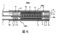
- FIG. 6 is a cross-sectional view of a multilayer structure 200b according to the third embodiment.
- FIG. 7 is an enlarged view of the vicinity of the negative electrode side insulating layer 10a of FIG.
- FIG. 8 is a cross-sectional view of a multilayer structure 200c according to the fourth embodiment.
- FIG. 9 is an enlarged view of the vicinity of the separator 3 in FIG.
- the laminated structure 200 (laminated structure of a nonaqueous secondary battery) according to the first embodiment will be described.
- the laminated structure 200 has a structure in which non-aqueous secondary batteries 100 are laminated.
- FIG. 1 illustrates a case where two non-aqueous secondary batteries 100 are stacked.
- FIG. 1 illustrates a case where two non-aqueous secondary batteries 100 are stacked.
- each non-aqueous secondary battery 100 includes a positive electrode current collector layer 1, a positive electrode layer 2 formed on one surface of the positive electrode current collector layer 1, and a negative electrode current collector layer 5.
- a negative electrode layer 4 formed on one surface of the negative electrode current collector layer 5 so as to face the positive electrode layer 2, a separator 3 provided between the positive electrode layer 2 and the negative electrode layer 4 and containing an electrolytic solution,
- a positive electrode side insulating layer 9 formed on the other surface of the positive electrode current collector layer 1, a negative electrode side insulating layer 10 formed on the other surface of the negative electrode current collector layer 5, the positive electrode layer 2 and the negative electrode layer 4.
- a multilayer structure having at least a positive electrode fusion layer 6, a gas barrier layer 7, and a negative electrode fusion layer 8 provided on the inner surface of the peripheral portion of the positive electrode current collector layer 1 and the inner surface of the peripheral portion of the five negative electrode current collector layers so as to surround. And a sealing agent.
- two (adjacent) non-aqueous secondary batteries 100 share one negative electrode side insulating layer 10, and the negative electrode current collector is sandwiched between the negative electrode side insulating layers 10.
- the body layer 5 (and the negative electrode layer 4) are configured to face each other.
- the stacked structure 200 is equivalent to the shared insulating layer. Can be made thinner. That is, in FIG. 3, there are four insulating layers (two positive-side insulating layers 9 and two negative-side insulating layers 10), but in FIG. 1, three insulating layers (two positive-side insulating layers 9 are two layers, The negative electrode side insulating layer 10 is one layer), and the thickness is reduced by one layer of the negative electrode side insulating layer 10. The above is the outline of the structure of the laminated structure 200. Next, each component of the non-aqueous secondary battery 100 will be described in more detail.
- the positive electrode layer 2 has an active material.
- lithium manganate such as spinel structure oxide LiMn 2 O 4
- LiNi 0.5 of the same spinel structure oxide is used.
- Mn 1.5 O 4 LiFePO 4 having an olivine structure oxide, LiMnPO 4, Li 2 CoPO 4 F, LiCoO 2 of layered rock salt structure oxide, LiNi 1-x-y Co x Al y O 2, LiNi 0.5 -X Mn 0.5-x Co 2x O 2 , solid solutions of these layered rock salt structure oxides and Li 2 MnO 3 , sulfur, nitroxyl radical polymers, and the like can also be used.
- a plurality of these positive electrode active materials may be mixed and used.
- Nitroxyl radical polymer is a flexible positive electrode active material, unlike other oxides, and is therefore preferred as a positive electrode active material for a flexible thin non-aqueous secondary battery built in an IC card.
- the content of the active material in the positive electrode is, for example, 90 wt%, but can be arbitrarily adjusted. If it is 10 wt% or more with respect to the whole weight of the positive electrode, a sufficient capacity can be obtained, and if it is desired to obtain a capacity as large as possible, it is preferably 50 wt% or more, particularly 80 wt% or more.
- the positive electrode layer 2 has a conductivity imparting agent.
- the conductivity-imparting agent for example, graphite powder and acetylene black having an average particle diameter of 6 ⁇ m can be used, but a conventionally known conductivity-imparting material may be used.
- Examples of conventionally known conductivity imparting agents include carbon black, furnace black, vapor grown carbon fiber, carbon nanotube, carbon nanohorn, metal powder, and conductive polymer.
- the positive electrode layer 2 contains a binder.
- polyvinylidene fluoride can be used as the binder, but a conventionally known binder may be used.
- the positive electrode layer 2 is prepared, for example, by dispersing the above-described materials in a solvent to prepare a positive ink, printing and applying, and removing the dispersed solvent by heating and drying.
- a solvent for example, N-methylpyrrolidone (NMP), water, tetrahydrofuran, and the like can be used.
- the negative electrode layer 4 has an active material.
- the negative electrode active material contained in the negative electrode layer 4 graphite such as mesocarbon microbeads (hereinafter referred to as MCMB) can be used, but it is not necessarily limited thereto.
- MCMB mesocarbon microbeads
- it can be replaced with a conventionally known negative electrode active material.
- conventionally known negative electrode active materials include carbon materials such as activated carbon and hard carbon, lithium metal, lithium alloy, lithium ion occlusion carbon, and various other simple metals and alloys.
- the negative electrode layer 4 has a conductivity imparting agent.
- the conductivity-imparting agent for example, a material mainly composed of acetylene black can be used, but a conventionally known conductivity-imparting agent may be used.
- Examples of conventionally known conductivity imparting agents include carbon black, acetylene black, graphite, furnace black, vapor grown carbon fiber, carbon nanotube, carbon nanohorn, metal powder, and conductive polymer.
- the negative electrode layer 4 has a binder.
- polyvinylidene fluoride can be used as the binder, but a conventionally known binder may be used.
- the negative electrode layer 4 is prepared, for example, by dispersing the above-described materials in a solvent to prepare a negative ink, printing and applying, and removing the dispersed solvent by heat drying.
- a solvent for example, NMP, water, tetrahydrofuran and the like can be used.
- the separator 3 according to the present invention is interposed between the positive electrode layer 2 and the negative electrode layer 4, and plays a role of conducting only ions without conducting electrons by containing an electrolytic solution.
- material is not specifically limited, A conventionally well-known thing can be used. Specific examples of the material include polyolefins such as polypropylene and polyethylene, porous films such as fluororesin, nonwoven fabrics, and glass filters.
- the electrolytic solution transports the charge carrier between the positive electrode layer 2 and the negative electrode layer 4, and generally has an ionic conductivity of 10 ⁇ 5 to 10 ⁇ 1 S / cm at room temperature.
- EC ethylene carbonate
- DEC diethyl carbonate
- LiPF 6 lithium hexafluorophosphate
- a conventionally known electrolytic solution may be used.
- a conventionally well-known electrolyte solution what melt
- solvents examples include organic solvents such as ethylene carbonate, propylene carbonate, dimethyl carbonate, diethyl carbonate, methyl ethyl carbonate, ⁇ -butyrolactone, tetrahydrofuran, dioxolane, sulfolane, dimethylformamide, dimethylacetamide, and N-methyl-2-pyrrolidone.
- organic solvents such as ethylene carbonate, propylene carbonate, dimethyl carbonate, diethyl carbonate, methyl ethyl carbonate, ⁇ -butyrolactone, tetrahydrofuran, dioxolane, sulfolane, dimethylformamide, dimethylacetamide, and N-methyl-2-pyrrolidone.
- a solvent, a sulfuric acid aqueous solution, water, etc. are mentioned. In the present invention, these solvents may be used alone or in combination of two or more.
- the electrolyte salt examples include LiPF 6 , LiClO 4 , LiBF 4 , LiCF 3 SO 3 , LiN (CF 3 SO 2 ) 2 , LiN (C 2 F 5 SO 2 ) 2 , LiC (CF 3 SO 2 ) 3. And lithium salts such as LiC (C 2 F 5 SO 2 ) 3 .
- the concentration of the electrolyte salt is not particularly limited to 1.0M.
- the positive electrode current collector layer 1 is preferably formed of a material containing aluminum as a main component, for example, an aluminum foil, but is not particularly limited to aluminum, and a conventionally known material can be used. Specific examples of the material include nickel, copper, gold, silver, titanium, and an aluminum alloy.
- the thickness of the positive electrode current collector layer 1 is, for example, about 40 ⁇ m, but is not necessarily limited thereto. However, from the viewpoint of gas permeability, it is preferably 12 ⁇ m or more, and more preferably 30 ⁇ m or more. Further, from the viewpoint of energy density, it is preferably 100 ⁇ m or less, and more preferably 68 ⁇ m or less.
- the negative electrode current collector layer 5 is preferably formed of a material containing copper as a main component, for example, a copper foil, but is not particularly limited to copper, and a conventionally known material can be used. Specific materials include materials such as nickel, aluminum, gold, silver, titanium, and aluminum alloy.
- the thickness of the negative electrode current collector layer 5 is, for example, about 18 ⁇ m, but is not necessarily limited thereto. However, from the viewpoint of gas permeability, it is preferably 8 ⁇ m or more, and more preferably 15 ⁇ m or more. Further, from the viewpoint of energy density, it is preferably 50 ⁇ m or less, and more preferably 30 ⁇ m or less.
- the sealant is for preventing water vapor or the like from coming into contact with the power generation elements (the positive electrode layer 2, the negative electrode layer 4, the separator 3, etc.) of the thin non-aqueous secondary battery, and at least the positive electrode fusion layer 6 And a multilayer structure having a gas barrier layer 7 and a negative electrode fusion layer 8.
- each layer is laminated and integrated separately, or a multilayer structure sealing agent is prepared and sandwiched in advance.
- a multilayer structure sealing agent is prepared and sandwiched in advance.
- at least the positive electrode fusion layer 6, the gas barrier layer 7, and the negative electrode fusion layer 8 are considered. The same effect can be expected if a multi-layer sealant is used.
- a three-layer film of modified polyolefin resin / liquid crystal polyester / modified polyolefin or ionomer resin / liquid crystal polyester resin / ionomer resin is sandwiched between the positive electrode current collector layer 1 and the negative electrode current collector layer 5. It is desirable to use in.
- the modified polyolefin resin refers to a resin obtained by graft-modifying polar groups such as maleic anhydride, acrylic acid, and glycidyl methacrylic acid on polyethylene or polypropylene
- the ionomer resin refers to, for example, ethylene- It is a resin having a special structure in which molecules of methacrylic acid copolymer or ethylene-acrylic acid copolymer are intermolecularly bonded with metal ions such as sodium and zinc.
- the gas barrier layer 7 plays a role of preventing permeation of water vapor gas from the outside to the inside of the battery and preventing a short circuit between the positive electrode current collector layer 1 and the negative electrode current collector layer 5.
- the material of the gas barrier layer 7 is not particularly limited, but is preferably a liquid crystal polyester resin because it has excellent gas barrier properties, excellent insulating properties, and flexibility and bending resistance.
- the liquid crystal polyester resin is, for example, a liquid crystal polymer such as a thermotropic liquid crystal polyester or a liquid crystal polyester amide (thermotropic liquid crystal polyester amide) synthesized mainly from monomers such as an aromatic dicarboxylic acid and an aromatic diol or an aromatic hydroxycarboxylic acid ( It is a general term including a thermotropic liquid crystal polymer).
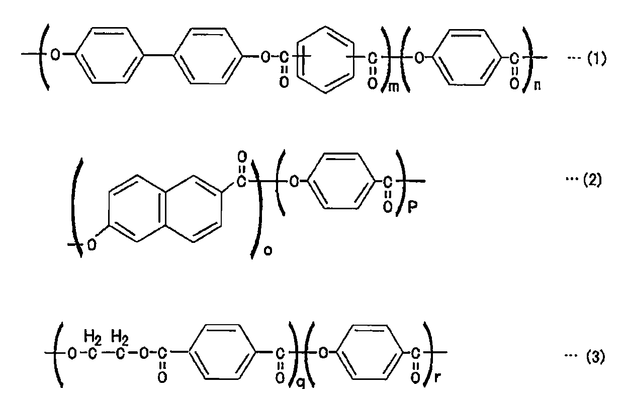
- liquid crystalline polyester resin examples include type I (formula 1 below) synthesized from parahydroxybenzoic acid (PHB), terephthalic acid, and 4,4′-biphenol, PHB and 2,6-hydroxy.
- Type II synthesized from naphthoic acid (Formula 2 below)
- Type III synthesized from PHB and terephthalic acid and ethylene glycol (Formula 3 below).
- the liquid crystal polyester resin in the present invention may be any of type I to type III, but from the viewpoints of heat resistance, dimensional stability, and water vapor barrier properties, wholly aromatic liquid crystal polyesters (type I and type II) and wholly aromatic A liquid crystal polyester amide is preferred.
- the liquid crystal polyester resin in the present invention includes a polymer blend with other components in which the liquid crystal polyester resin is contained in a ratio of 60 wt% or more, and a mixed composition with an inorganic filler or the like.
- the form of the gas barrier layer 7 is not particularly limited, but is preferably a film that can be easily processed.
- the film in the present invention is a concept including a sheet, a plate, and a foil (particularly, regarding a constituent material of a metal layer). In obtaining such a substrate, a conventionally known production method according to the resin constituting the substrate can be used.
- a film using the said liquid crystalline polyester resin especially suitable in this invention "BIAC-CB (brand name)" by Japan Gore-Tex Co., Ltd.
- the thickness of the gas barrier layer 7 in the present invention is not particularly limited, but if it is too thin, there will be a problem with the insulating properties, and if it is too thick, there will be a problem with the gas barrier property. Accordingly, the thickness of the gas barrier layer 7 is, for example, 1 ⁇ m to 700 ⁇ m, preferably 5 ⁇ m to 200 ⁇ m, more preferably 10 ⁇ m to 100 ⁇ m, and most preferably 10 ⁇ m to 60 ⁇ m.
- the positive electrode fusion layer 6 and the negative electrode fusion layer 8 serve to fuse the gas barrier layer 7, the positive electrode current collector layer 1, and the negative electrode current collector layer 5.
- the materials for the positive electrode fusion layer 6 and the negative electrode fusion layer 8 are not particularly limited, and examples thereof include modified polyolefin resins and ionomer resins.
- these resins may be used alone or in combination of several kinds.
- the resin used for the positive electrode fusion layer 6 and the negative electrode fusion layer 8 is inferior to the resin used for the gas barrier layer 7 in gas barrier properties, it is excellent in heat sealability. Therefore, by using the gas barrier layer 7 at the same time, it is possible to achieve both excellent gas barrier properties and heat sealing properties.
- the positive electrode side insulating layer 9 and the negative electrode side insulating layer 10 are for preventing a short circuit during work, and for example, a liquid crystal polymer resin (LCP) such as a liquid crystal polyester resin is used.
- LCP liquid crystal polymer resin
- PVDF polyvinylidene fluoride
- MCMB Mesocarbon microbeads
- the positive electrode layer 2 and the negative electrode layer 4 prepared by the above method are provided with a separator 3 containing an electrolytic solution between electrodes, and a modified polyolefin resin / liquid crystal polyester resin / modified polyolefin resin (positive electrode fusion layer 6 /
- the three layers of sealing agent gas barrier layer 7 / negative electrode fusion layer 8) were made to face each other with a film formed in a mouth shape (peripheral shape with the center portion punched out).
- EC ethylene carbonate
- DEC diethyl carbonate
- 1.0 M LiPF 6 as a supporting salt
- the laminated structure 200 was produced by the above procedure.
- the stacked structure 200 has a structure in which the non-aqueous secondary batteries 100 are stacked, and the two non-aqueous secondary batteries 100 share one negative-side insulating layer 10.
- the negative electrode current collector layer 5 is opposed so as to sandwich one negative electrode side insulating layer 10. Therefore, compared with the case where the nonaqueous secondary battery 100 is simply laminated, the laminated structure 200 can be made thinner by the shared insulating layer.
- a second embodiment will be described with reference to FIG. 4 and FIG.
- an opening 21 is provided in the negative electrode-side insulating layer 10a in the first embodiment, and the negative electrode layer 4 of one nonaqueous secondary battery 100b is embedded.
- elements having the same functions as those in the first embodiment are denoted by the same reference numerals and description thereof is omitted. As shown in FIG.
- the laminated structure 200a according to the second embodiment has a structure in which the non-aqueous secondary batteries 100a and 100b are laminated, and the non-aqueous secondary batteries 100a and 100b are composed of a negative electrode side insulating layer. 10a is shared.
- the negative electrode side insulating layer 10a a portion facing the negative electrode layer 4 is opened to form an opening 21, and the opening 21 has a negative electrode layer of the nonaqueous secondary battery 100b. 4 is buried. Therefore, the negative electrode layer 4 of the non-aqueous secondary battery 100 a and the negative electrode layer 4 of the non-aqueous secondary battery 100 b are both in contact with one negative electrode current collector layer 5.
- the non-aqueous secondary batteries 100 a and 100 b share not only the negative electrode side insulating layer 10 but also the negative electrode current collector layer 5.
- the laminated structure 200a can be further thinned. Specifically, as compared with the case where the nonaqueous secondary battery 100 is simply laminated as shown in FIG. 3, the laminated structure 200 a has fewer negative electrode-side insulating layers 10 a and negative electrode collector layers 5, respectively. And since one layer of the negative electrode layer 4 is embed
- the opening 21 is obtained, for example, by etching the portion facing the negative electrode layer 4 after forming the negative electrode current collector layer 5 on one surface of the negative electrode side insulating layer 10a.
- the negative electrode layer 4 is formed by applying a negative electrode active material to a portion exposed from the opening 21 of the negative electrode current collector layer 5 and further applying a negative electrode active material to the opposite surface. And formed on both surfaces of the negative electrode current collector layer 5.
- the stacking structure 200a has a structure in which the non-aqueous secondary batteries 100a and 100b are stacked, and the two non-aqueous secondary batteries 100a have one negative-side insulating layer. 10a is shared. Accordingly, the same effects as those of the first embodiment are obtained.
- the negative electrode-side insulating layer 10a is formed with an opening 21 at a portion facing the negative electrode layer 4, and the opening 21 has a non-aqueous secondary battery 100b.
- the negative electrode layer 4 is embedded, and the negative electrode layer 4 of the non-aqueous secondary battery 100 a and the negative electrode layer 4 of the non-aqueous secondary battery 100 b are both in contact with one negative electrode current collector layer 5. Therefore, the nonaqueous secondary batteries 100a and 100b share not only the negative electrode side insulating layer 10a but also the negative electrode current collector layer 5 and can be further reduced in thickness as compared with the first embodiment.
- a mesh portion 23 is formed by providing a through hole in a part of the contact surface of the negative electrode current collector layer 5 with the negative electrode layer 4 in the second embodiment.
- elements that perform the same functions as those in the second embodiment are denoted by the same reference numerals, and description thereof is omitted.
- the laminated structure 200b according to the third embodiment has a structure in which non-aqueous secondary batteries 100a and 100c are laminated.
- the negative electrode current collector layer Through holes are provided in part of the contact surface with the negative electrode layer 4 of 5 to form a mesh portion 23.
- the negative electrode active material may be applied only to one surface of the mesh portion 23. Then, since the negative electrode active material also flows from the opening of the mesh portion 23 to the other surface, the negative electrode layer 4 is formed on the other surface. That is, by providing the mesh portion 23, the negative electrode layer 4 can be formed on both surfaces of the negative electrode current collector layer 5 simply by applying the negative electrode active material to one surface of the mesh portion 23, thereby reducing manufacturing costs. I can do it.
- the mesh part 23 it is desirable to contain lithium as a negative electrode active material.
- the negative electrode-side insulating layer 10a has the opening 21 formed through the portion in contact with the negative electrode layer 4, and the non-aqueous secondary battery is formed in the opening 21.
- the negative electrode layer 4 of 100 c is embedded, and the negative electrode layer 4 of the nonaqueous secondary battery 100 a and the negative electrode layer 4 of the nonaqueous secondary battery 100 c are both in contact with one negative electrode current collector layer 5. Accordingly, the same effects as those of the second embodiment are combined. Further, according to the third embodiment, a part of the portion of the negative electrode current collector layer 5 that contacts the negative electrode layer 4 is opened to form the mesh portion 23.
- the negative electrode layer 4 can be formed on both surfaces of the negative electrode current collector layer 5 only by applying the negative electrode active material to one surface of the mesh portion 23, and the manufacturing cost is reduced as compared with the second embodiment. I can do it.
- a fourth embodiment will be described with reference to FIGS.
- the separator 3 is sandwiched between sealing agents in the first embodiment. Note that in the fourth embodiment, elements that perform the same functions as in the first embodiment are denoted by the same reference numerals, and descriptions thereof are omitted.
- the laminated structure 200C according to the fourth embodiment has a structure in which non-aqueous secondary batteries 100d are laminated, and the non-aqueous secondary battery 100d includes one negative-side insulating layer 10.
- the negative electrode current collector layer 5 is opposed so as to sandwich the negative electrode side insulating layer 10.
- the separator 3 is sandwiched between sealing agents. Specifically, in FIG. 9, the separator 3 is sandwiched between the gas barrier layer 7 and the negative electrode fusion layer 8.
- the separator 3 is sandwiched between the gas barrier layer 7 and the negative electrode fusion layer 8.
- the thickness of the positive electrode layer 2 is usually thicker than that of the negative electrode layer 4, so that the mounting position of the separator is less than sandwiched between the positive electrode fusion layer 6 and the gas barrier layer 7.
- the sandwiching between the gas barrier layer 7 and the negative electrode fusion layer 8 is preferable because the stress concentration on the separator 3 is suppressed and a battery having long-term reliability can be manufactured.
- the stacked structure 200c has a structure in which the nonaqueous secondary batteries 100d are stacked, and the two nonaqueous secondary batteries 100d include one negative insulating layer 10. And the negative electrode current collector layer 5 is opposed so as to sandwich the negative electrode-side insulating layer 10 therebetween. Accordingly, the same effects as those of the first embodiment are obtained.
- the separator 3 of the non-aqueous secondary battery 100d is sandwiched between the sealing agents. Therefore, the handling of the separator is facilitated, the non-aqueous secondary battery 100d is easily manufactured, and the manufacturing speed of the laminated structure 200c can be increased.
- Example 1 A non-aqueous secondary battery 100 constituting the laminated structure 200 according to the present invention was produced under the following conditions.
- Example 1 90 wt% of lithium manganate having a spinel structure, 5 wt% of graphite powder having an average particle diameter of 6 ⁇ m as a conductivity imparting agent, 2 wt% of acetylene black, and 3 wt% of PVDF as a binder are weighed, and N-methylpyrrolidone (hereinafter referred to as NMP). ) was dispersed and mixed into a positive electrode ink.
- NMP N-methylpyrrolidone
- the positive electrode ink produced by the method described above was applied by screen printing on a 40 ⁇ m thick aluminum foil with a 50 ⁇ m thick liquid crystal polyester bonded to the back side, and NMP as a dispersion solvent was removed by heating and drying. Thereafter, it was compression-molded with a roller press to produce a positive electrode having a thickness of 140 ⁇ m including liquid crystal polyester and aluminum foil.
- MCMB manufactured by Osaka Gas graphitized at 2800 ° C. was used as the negative electrode active material.
- MCMB was 88 wt%
- acetylene black was 2 wt% as a conductivity imparting agent
- PVDF was 10 wt% as a binder, and dispersed and mixed in NMP to obtain a negative ink.
- the negative electrode ink produced by the above method was applied onto a copper foil having a thickness of 18 ⁇ m with a liquid crystal polyester having a thickness of 50 ⁇ m bonded to the back surface by screen printing, and NMP as a dispersion solvent was removed by heating and drying. Thereafter, it was compression-molded with a roller press to produce a negative electrode having a thickness of 100 ⁇ m including liquid crystal polyester and copper foil.
- the positive electrode and the negative electrode produced by the above method were opposed to each other with a porous film separator interposed therebetween.
- a film in which three layers of a maleic anhydride-modified polypropylene / liquid crystal polyester / maleic anhydride-modified polypropylene each having a thickness of 50 ⁇ m were formed on the periphery of the electrode layer.
- Three sides of the obtained rectangular laminate were heat-sealed at a heater temperature of 190 ° C., and 60 ⁇ L of electrolyte was injected from the remaining one side.
- Example 2 90 wt% of cobalt aluminum substituted lithium nickelate (LiNi 0.80 Co 0.15 Al 0.05 O 2 ) having a layered rock salt structure, 5 wt% of graphite powder and 2 wt% of acetylene black as a conductivity-imparting agent 3% by weight of PVDF was weighed out as an agent, and dispersed and mixed in N-methylpyrrolidone (hereinafter NMP) to obtain a positive electrode ink.
- NMP N-methylpyrrolidone
- the positive electrode ink produced by the method described above was applied by screen printing on a 40 ⁇ m thick aluminum foil with a 50 ⁇ m thick liquid crystal polyester bonded to the back side, and NMP as a dispersion solvent was removed by heating and drying. Thereafter, it was compression-molded with a roller press to produce a positive electrode having a thickness of 140 ⁇ m including liquid crystal polyester and aluminum foil.
- MCMB manufactured by Osaka Gas graphitized at 2800 ° C. was used as the negative electrode active material.
- MCMB was 88 wt%
- acetylene black was 2 wt% as a conductivity imparting agent
- PVDF was 10 wt% as a binder, and dispersed and mixed in NMP to obtain a negative ink.
- the negative electrode ink produced by the above method was applied onto a copper foil having a thickness of 18 ⁇ m with a liquid crystal polyester having a thickness of 50 ⁇ m bonded to the back surface by screen printing, and NMP as a dispersion solvent was removed by heating and drying. Thereafter, it was compression-molded with a roller press to produce a negative electrode having a thickness of 120 ⁇ m including liquid crystal polyester and copper foil.
- the positive electrode and the negative electrode produced by the above method were opposed to each other with a porous film separator interposed therebetween.
- Example 3 70% organic radical polymer, poly (2,2,6,6-tetramethylpiperidinoxy-4-yl methacrylate), 14% vapor-grown carbon fiber, 7% acetylene black, 8% carboxymethylcellulose, Teflon (registered) Trademark) 1% was weighed out, dispersed and mixed in water to obtain a positive electrode ink.
- the positive electrode ink produced by the above method was printed on the aluminum foil having a thickness of 40 ⁇ m bonded to the back surface with a liquid crystal polyester having a thickness of 50 ⁇ m by a screen printing method, and water as a dispersion solvent was removed by heating and drying. Thereafter, it was compression-molded with a roller press to produce a positive electrode having a thickness of 170 ⁇ m including liquid crystal polyester and aluminum foil.
- MCMB manufactured by Osaka Gas graphitized at 2800 ° C. was used as the negative electrode active material.
- MCMB was 88 wt%
- acetylene black was 2 wt% as a conductivity imparting agent
- PVDF was 10 wt% as a binder
- the negative electrode ink produced by the above method was applied onto a copper foil having a thickness of 18 ⁇ m with a liquid crystal polyester having a thickness of 50 ⁇ m bonded to the back surface by screen printing, and NMP as a dispersion solvent was removed by heating and drying. Thereafter, it was compression-molded with a roller press to produce a negative electrode having a thickness of 100 ⁇ m including liquid crystal polyester and copper foil.
- the positive electrode and the negative electrode produced by the above method were opposed to each other with a porous film separator interposed therebetween.
- a film in which a three-layer sealing agent of glycidyl methacrylate-modified polyethylene / liquid crystal polyester / glycidyl methacrylate-modified polyethylene with a thickness of 100 ⁇ m was formed in the shape of a mouth was sandwiched between the peripheral portions of the electrode layers.
- Three sides of the obtained rectangular laminate were heat-fused at a heater temperature of 150 ° C., and 60 ⁇ L of electrolyte solution was injected from the remaining one side.
- the whole cell was decompressed and the electrolyte was thoroughly impregnated in the gap, and then the remaining one side was heated and fused in a decompressed state to obtain a thin secondary battery.
- a comparative example a non-aqueous secondary battery was manufactured under conditions different from those in Examples 1 to 3.
- MCMB manufactured by Osaka Gas graphitized at 2800 ° C. was used as the negative electrode active material.
- MCMB was 88 wt%
- acetylene black was 2 wt% as a conductivity imparting agent
- PVDF was 10 wt% as a binder, and dispersed and mixed in NMP to obtain a negative ink.
- the negative electrode ink produced by the above method was applied onto a copper foil having a thickness of 18 ⁇ m with a liquid crystal polyester having a thickness of 50 ⁇ m bonded to the back surface by screen printing, and NMP as a dispersion solvent was removed by heating and drying. Thereafter, it was compression-molded with a roller press to produce a negative electrode having a thickness of 100 ⁇ m including liquid crystal polyester and copper foil.
- the positive electrode and the negative electrode produced by the above method were opposed to each other with a porous film separator interposed therebetween. In that case, the film which shape
- the whole cell was decompressed and the electrolyte was thoroughly impregnated in the gap, and then the remaining one side was heated and fused in a decompressed state to obtain a thin secondary battery.
- MCMB manufactured by Osaka Gas graphitized at 2800 ° C. was used as the negative electrode active material.
- MCMB was 88 wt%
- acetylene black was 2 wt% as a conductivity imparting agent
- PVDF was 10 wt% as a binder, and dispersed and mixed in NMP to obtain a negative ink.
- the negative electrode ink produced by the above method was applied onto a copper foil having a thickness of 18 ⁇ m with a liquid crystal polyester having a thickness of 50 ⁇ m bonded to the back surface by screen printing, and NMP as a dispersion solvent was removed by heating and drying. Thereafter, it was compression-molded with a roller press to produce a negative electrode having a thickness of 100 ⁇ m including liquid crystal polyester and copper foil.
- the positive electrode and the negative electrode produced by the above method were opposed to each other with a porous film separator interposed therebetween. In that case, the film which shape
- the positive electrode ink produced by the above method was printed and applied by screen printing on an aluminum foil having a thickness of 10 ⁇ m and a liquid crystal polyester having a thickness of 50 ⁇ m bonded to the back surface, and NMP as a dispersion solvent was removed by heating and drying. Thereafter, it was compression-molded with a roller press to produce a positive electrode having a thickness of 140 ⁇ m including liquid crystal polyester and aluminum foil.
- MCMB manufactured by Osaka Gas graphitized at 2800 ° C. was used as the negative electrode active material.
- MCMB was 88 wt%
- acetylene black was 2 wt% as a conductivity imparting agent
- PVDF was 10 wt% as a binder
- the negative electrode ink produced by the above method was applied onto a copper foil having a thickness of 18 ⁇ m with a liquid crystal polyester having a thickness of 50 ⁇ m bonded to the back surface by screen printing, and NMP as a dispersion solvent was removed by heating and drying. Thereafter, it was compression-molded with a roller press to produce a negative electrode having a thickness of 100 ⁇ m including liquid crystal polyester and copper foil.
- the positive electrode and the negative electrode produced by the above method were opposed to each other with a porous film separator interposed therebetween.
- denatured polyethylene each in the shape of a mouth was pinched
- Three sides of the obtained rectangular laminate were heat-fused at a heater temperature of 150 ° C., and 60 ⁇ L of electrolyte solution was injected from the remaining one side.
- NMP N-methylpyrrolidone
- the positive electrode ink produced by the above method was printed and applied by a screen printing method onto an aluminum foil having a thickness of 70 ⁇ m and a liquid crystal polyester having a thickness of 50 ⁇ m bonded to the back surface, and NMP as a dispersion solvent was removed by heating and drying. Thereafter, it was compression-molded with a roller press to produce a positive electrode having a thickness of 140 ⁇ m including liquid crystal polyester and aluminum foil.
- MCMB manufactured by Osaka Gas graphitized at 2800 ° C. was used as the negative electrode active material.
- MCMB was 88 wt%
- acetylene black was 2 wt% as a conductivity imparting agent
- PVDF was 10 wt% as a binder
- the negative electrode ink produced by the above method was applied onto a copper foil having a thickness of 18 ⁇ m with a liquid crystal polyester having a thickness of 50 ⁇ m bonded to the back surface by screen printing, and NMP as a dispersion solvent was removed by heating and drying. Thereafter, it was compression-molded with a roller press to produce a negative electrode having a thickness of 100 ⁇ m including liquid crystal polyester and copper foil.
- the positive electrode and the negative electrode produced by the above method were opposed to each other with a porous film separator interposed therebetween.
- a film in which three layers of a maleic anhydride-modified polypropylene / liquid crystal polyester / maleic anhydride-modified polypropylene having a thickness of 100 ⁇ m were formed in the shape of a mouth was sandwiched between the peripheral portions of the electrode layers.
- Three sides of the obtained rectangular laminate were heat-sealed at a heater temperature of 190 ° C., and 60 ⁇ L of electrolyte was injected from the remaining one side.
- the whole cell was decompressed and the electrolyte was thoroughly impregnated in the gap, and then the remaining one side was heated and fused in a decompressed state to obtain a thin secondary battery.
- ⁇ Evaluation of cell> In the method of Comparative Example 2, a cell could not be manufactured as described above. Therefore, the cells prepared in Examples 1 to 3 and Comparative Examples 1, 3, and 4 were placed in a constant temperature bath at 20 ° C., and initial charge / discharge was performed at a rate of 0.1 C.
- the non-aqueous electrolyte secondary battery according to the present invention is a thin battery that does not use an aluminum laminate film outer package, it has high adhesion to a bipolar collector, high short-circuit prevention reliability, and sufficient gas barrier properties at the same time. Since it can be satisfied, it can be widely used as a thin non-aqueous electrolyte secondary battery that is easy to use.
- Examples of utilization of the present invention include IC cards, RFID tags, various sensors, and portable electronic devices.
- the present invention is not limited to the embodiments and examples described above. It is natural for those skilled in the art to come up with various modifications and improvements within the scope of the present invention, and it is understood that these are also included in the present invention.
- a laminated structure in which the negative electrode side insulating layer 10 or the negative electrode current collector layer 5 is shared is disclosed, but a structure in which the positive electrode side insulating layer 9 or the positive electrode current collector layer 1 is shared may be used.
- this application claims the profit on the basis of the priority from the Japan patent application 2011-105894 for which it applied on May 11, 2011, The indication is as a whole here. Incorporated as a reference.
Abstract
Description
一方、近年では様々なタイプのICカードや非接触型ICカードが普及しており、非接触型ICカードの多くは、電磁誘導コイルで電力を発生させ、使用時のみ電気回路が作動するシステムになっている。これらのICカードに表示機能やセンシング機能を持たせ、セキュリティー面や利便性を大きく向上させるためには、エネルギー源となる二次電池を内蔵させることが望ましい。ICカードの大きさは例えば85mm×48mm×0.76mmと規格化されているため、内蔵される二次電池の厚みは0.76mm以下であることが要求される。また規格に当てはまらない各種カード型デバイスでも、二次電池の厚みは2.5mm以下であることが好ましい。そのため、上述した金属缶を用いた二次電池を用いることは困難である。
厚み2.5mm以下の薄型非水系二次電池としては、外装体にアルミラミネートフィルムを用いたものがある。アルミラミネートフィルムは、主に熱可塑性樹脂層、アルミニウム箔層及び絶縁体層を有しており、十分なガスバリア性を有しながらも容易に成形、加工ができるという特徴がある。しかしながら、薄型非水系二次電池の場合、電池全体の厚みに占める外装体の比率が高いため、エネルギー密度を高めるためには外装体をできるだけ薄くする技術が要求される。
特許文献1には、最内層、第1接着層、第1表面処理層、アルミニウム箔層、第2表面処理層、第2接着層及び最外装の7層構造のアルミラミネートフィルムが示されており、優れた成形性、ガスバリア性、ヒートシール性及び耐電解液性が得られている(特許文献1)。
特許文献2には、正極集電体および負極集電体が外装体を兼ねることで、アルミラミネートを必要としない薄型電池が提案されている。この電池では、正極集電体および負極集電体の周縁部が、ポリオレフィンもしくはエンジニアリングプラスチックの封口剤で接合されている(特許文献2)。
特許文献3にも、正極集電体及び負極集電体が外装体を兼ねることで、アルミラミネートを必要としない薄型電池が提案されている。この文献には、正極集電体および負極集電体の周縁部が、オレフィン系ホットメルト樹脂、ウレタン系反応型ホットメルト樹脂、エチレンビニルアルコール系ホットメルト樹脂、ポリアミド系ホットメルト樹脂などで接合されること、及びこれらのホットメルト樹脂に無機フィラーを充填させることが提案されている(特許文献3)。
また、特許文献4では、アルミニウムの正極集電体と、同じくアルミニウムの負極集電体とで電解質を挟み込み、溶着層とガスバリア層を有する多層構造で隙間を埋めた電気二重層キャパシタの構造が開示されている(特許文献4)。即ち、特許文献4は、正極集電体と負極集電体を同一のアルミニウムによって形成した電気二重層キャパシタを開示している。 Lithium ion secondary batteries, which are non-aqueous secondary batteries with high energy density, are used as power sources used in various portable devices such as mobile phones and notebook computers. The shape is mainly cylindrical and rectangular, and in many cases, it is formed by inserting a wound electrode laminate into a metal can. Although it is required to reduce the thickness of the battery depending on the type of portable device, a metal can made by deep drawing is difficult to make the
On the other hand, in recent years, various types of IC cards and non-contact type IC cards have become widespread, and most of non-contact type IC cards are systems that generate electric power with an electromagnetic induction coil and operate an electric circuit only when used. It has become. In order to provide these IC cards with a display function and a sensing function and greatly improve security and convenience, it is desirable to incorporate a secondary battery as an energy source. Since the size of the IC card is standardized to, for example, 85 mm × 48 mm × 0.76 mm, the thickness of the built-in secondary battery is required to be 0.76 mm or less. Even in various card type devices that do not meet the standards, the thickness of the secondary battery is preferably 2.5 mm or less. Therefore, it is difficult to use a secondary battery using the metal can described above.
As a thin non-aqueous secondary battery having a thickness of 2.5 mm or less, there is a battery using an aluminum laminate film as an outer package. The aluminum laminate film mainly has a thermoplastic resin layer, an aluminum foil layer, and an insulator layer, and is characterized in that it can be easily formed and processed while having a sufficient gas barrier property. However, in the case of a thin non-aqueous secondary battery, since the ratio of the outer package to the total thickness of the battery is high, a technique for making the outer package as thin as possible is required to increase the energy density.
この場合、そのまま積層すれば電池間の接着厚さや、接合部の外装体の基材部分の厚みが問題となってくる。
しかしながら、上記文献記載の発明は、いずれも積層した際の薄型化を考慮した構造となっていないという問題があった。
また、上記文献記載の発明では、電池組み立てにおいてセパレータの取り扱いが問題となる場合があった。
具体的には、セパレータは例えば極薄のポリオレフィン系多孔膜で構成されるが、このような構造では縮み易く、静電気を帯び易いため、正極層および負極層に密着させることや、その際に正確に位置決めを行うことが困難であった。
本発明は上記理由に鑑みてなされたものであり、その目的は、多層化が容易であり、かつ製造が容易な二次電池の積層構造を提供することにある。 Here, when capacity expansion is considered in a structure in which the positive electrode current collector and the negative electrode current collector also serve as an outer package, it is necessary to perform lamination when the area is limited.
In this case, if the layers are laminated as they are, the thickness of the bonding between the batteries and the thickness of the base material portion of the exterior body of the joint portion become problems.
However, the inventions described in the above documents have a problem that none of them has a structure that takes into account a reduction in thickness when stacked.
Moreover, in the invention described in the above-mentioned document, handling of the separator sometimes becomes a problem in battery assembly.
Specifically, the separator is composed of, for example, an ultra-thin polyolefin-based porous film. However, in such a structure, the separator is easily shrunk and easily charged with static electricity. It was difficult to perform positioning.
The present invention has been made in view of the above reasons, and an object of the present invention is to provide a laminated structure of a secondary battery that can be easily multilayered and easily manufactured.
本発明の第2の態様は、正極集電体層と、前記正極集電体層の一方の面に形成された正極層と、負極集電体層と、前記正極層に対向するように前記負極集電体層の一方の面に形成された負極層と、前記正極層と前記負極層の間に設けられ、電解液を含むセパレータと、前記正極集電体層の他の面に形成された正極側絶縁層と、前記負極集電体層の他の面に形成された負極側絶縁層と、前記正極層および前記負極層を囲むように、前記正極集電体層周縁部の内面および前記負極集電体層周縁部の内面に設けられ、少なくとも正極融着層、ガスバリア層、負極融着層を有する多層構造の封口剤と、を有する複数の非水系二次電池を、隣りあう前記非水系二次電池が、前記正極側絶縁層および/または前記負極側絶縁層を共有するように積層することを特徴とする非水系二次電池の積層方法である。 In order to achieve the above-described object, the first aspect of the present invention includes a positive electrode current collector layer, a positive electrode layer formed on one surface of the positive electrode current collector layer, a negative electrode current collector layer, A negative electrode layer formed on one surface of the negative electrode current collector layer so as to face the positive electrode layer; a separator provided between the positive electrode layer and the negative electrode layer and containing an electrolyte; and the positive electrode current collector A positive electrode side insulating layer formed on the other surface of the body layer; a negative electrode side insulating layer formed on the other surface of the negative electrode current collector layer; and the positive electrode so as to surround the positive electrode layer and the negative electrode layer. A plurality of non-sealing agents provided on the inner surface of the current collector layer peripheral portion and the inner surface of the negative electrode current collector layer peripheral portion and having at least a positive electrode fusion layer, a gas barrier layer, and a negative electrode fusion layer. The non-aqueous secondary battery adjacent to each other has a structure in which aqueous secondary batteries are stacked. It has a laminated structure of a nonaqueous secondary battery, characterized by sharing the negative electrode insulating layer.
The second aspect of the present invention is the positive electrode current collector layer, the positive electrode layer formed on one surface of the positive electrode current collector layer, the negative electrode current collector layer, and the positive electrode layer so as to face the positive electrode layer. A negative electrode layer formed on one surface of the negative electrode current collector layer, a separator provided between the positive electrode layer and the negative electrode layer, containing an electrolytic solution, and formed on the other surface of the positive electrode current collector layer A positive electrode side insulating layer, a negative electrode side insulating layer formed on the other surface of the negative electrode current collector layer, an inner surface of the peripheral portion of the positive electrode current collector layer so as to surround the positive electrode layer and the negative electrode layer, and A plurality of non-aqueous secondary batteries that are provided on the inner surface of the peripheral edge portion of the negative electrode current collector layer and have at least a positive electrode fusion layer, a gas barrier layer, and a multilayer structure sealing agent having a negative electrode fusion layer; A non-aqueous secondary battery is laminated so as to share the positive electrode side insulating layer and / or the negative electrode side insulating layer. Which is a method of laminating a non-aqueous secondary battery, wherein.
また、本発明によれば、積層化による容量拡大を行なった場合においても、1層と同じ製造方法を用い、かつ電池全体を薄くすることができるため、信頼性の高い電池実装を実現し、さらにこの電池を使用するアプリケーションの稼働時間を延ばすことが可能となる。また、封口剤とセパレータが一体成型されているため、実装が容易となり低コストで電池を提供することが可能となる。 According to the present invention, it is possible to provide a laminated structure of a secondary battery that can be easily multilayered and easily manufactured.
In addition, according to the present invention, even when the capacity is expanded by stacking, the same manufacturing method as that for one layer can be used and the entire battery can be thinned. Furthermore, it becomes possible to extend the operating time of the application using this battery. In addition, since the sealing agent and the separator are integrally molded, mounting is facilitated and a battery can be provided at low cost.
図2は積層構造200を構成する非水系二次電池100の構造を示す断面図である。
図3は非水系二次電池100を単純に積層した場合の積層構造201を示す断面図である。
図4は第2の実施形態に係る積層構造200aの断面図である。
図5は図4の負極側絶縁層10a付近の拡大図である。
図6は第3の実施形態に係る積層構造200bの断面図である。
図7は図6の負極側絶縁層10a付近の拡大図である。
図8は第4の実施形態に係る積層構造200cの断面図である。
図9は図8のセパレータ3付近の拡大図である。 FIG. 1 is a cross-sectional view of a laminated
FIG. 2 is a cross-sectional view showing the structure of the nonaqueous
FIG. 3 is a cross-sectional view showing a laminated
FIG. 4 is a cross-sectional view of a
FIG. 5 is an enlarged view of the vicinity of the negative electrode
FIG. 6 is a cross-sectional view of a
FIG. 7 is an enlarged view of the vicinity of the negative electrode
FIG. 8 is a cross-sectional view of a
FIG. 9 is an enlarged view of the vicinity of the
[構造]
まず、図1および図2を参照して、第1の実施形態に係る積層構造200(非水系二次電池の積層構造)の構造の概略について説明する。
図1に示すように、積層構造200は非水系二次電池100を積層した構造を有している。
図1では2つの非水系二次電池100を積層した場合を例示している。
個々の非水系二次電池100は、図2に示すように、正極集電体層1と、正極集電体層1の一方の面に形成された正極層2と、負極集電体層5と、正極層2に対向するように負極集電体層5の一方の面に形成された負極層4と、正極層2と負極層4の間に設けられ、電解液を含むセパレータ3と、正極集電体層1の他の面に形成された正極側絶縁層9と、負極集電体層5の他の面に形成された負極側絶縁層10と、正極層2および負極層4を囲むように、正極集電体層1周縁部の内面および負極集電体層5層周縁部の内面に設けられ、少なくとも正極融着層6、ガスバリア層7、負極融着層8を有する多層構造の封口剤と、を有している。
ここで、図2に示すように、(隣り合う)2つの非水系二次電池100は、1つの負極側絶縁層10を共有しており、負極側絶縁層10を挟み込むようにして負極集電体層5(および負極層4)が対向する構成となっている。
このように、絶縁層を共有することにより、図3に示すように、単純に非水系二次電池100を積層する積層構造201の場合と比べて、共有した絶縁層の分だけ、積層構造200の薄型化が可能となる。
即ち、図3では絶縁層は4層(正極側絶縁層9が2層、負極側絶縁層10が2層)あるが、図1では絶縁層は3層(正極側絶縁層9が2層、負極側絶縁層10が1層)であり、負極側絶縁層10の1層分だけ薄型化されている。
以上が積層構造200の構造の概略である。
次に、非水系二次電池100の各構成部材について、より詳細に説明する。
正極層2は活物質を有する。正極層2に含まれる活物質としては、例えばスピネル構造酸化物LiMn2O4等のマンガン酸リチウムを用いることができるが、必ずしもこれに限定されず、例えば同じスピネル構造酸化物のLiNi0.5Mn1.5O4、オリビン構造酸化物のLiFePO4、LiMnPO4、Li2CoPO4F、層状岩塩構造酸化物のLiCoO2、LiNi1−x−yCoxAlyO2、LiNi0.5−xMn0.5−xCo2xO2、これら層状岩塩構造酸化物とLi2MnO3との固溶体、硫黄、ニトロキシルラジカル高分子等を用いることもできる。また、これらの正極活物質を複数種類混合して用いてもよい。特にニトロキシルラジカル高分子は他の酸化物と異なり柔軟な正極活物質であるため、ICカードに内蔵するフレキシブルな薄型非水系二次電池向けの正極活物質として好ましい。
正極中における活物質の含有率は例えば90wt%であるが、任意に調整することができる。正極重量全体に対して10wt%以上であれば十分に容量が得られ、さらに、できるだけ大きな容量を得たい場合には50wt%以上、特に80wt%以上であることが好ましい。
正極層2に導電性を付与するため、正極層2は導電性付与剤を有する。導電性付与剤としては、例えば平均粒径6μmのグラファイト粉末およびアセチレンブラックを用いることができるが、従来公知の導電性付与剤材料を用いても良い。従来公知の導電性付与剤としては、例えば、カーボンブラックや、ファーネスブラック、気相成長炭素繊維、カーボンナノチューブ、カーボンナノホーン、金属粉末、導電性高分子等が挙げられる。
上記した材料を結着させるために、正極層2は結着剤を含有する。結着剤としては、例えばポリフッ化ビニリデンを用いることができるが、従来公知の結着剤を用いても良い。従来公知の結着剤としては、例えば、ポリテトラフルオロエチレン、ビニリデンフロライド−ヘキサフルオロプロピレン共重合体、スチレン−ブタジエン共重合ゴム、ポリプロピレン、ポリエチレン、ポリアクリロニトリル、アクリル樹脂等が挙げられる。
後述するように、正極層2は、例えば上記した材料を溶媒中に分散させて正極インクを作製して印刷塗布し、加熱乾燥により分散溶媒を除去することにより作製される。正極インクの分散溶媒としては従来公知のもの、具体的にはNメチルピロリドン(NMP)、水、テトラヒドロフランなどを用いることができる。
負極層4は活物質を有する。負極層4に含まれる負極活物質としてはメソカーボンマイクロビーズ(以下MCMB)等の黒鉛を用いることができるが、必ずしもこれには限定されない。例えば、従来公知の負極活物質に置き換えることもできる。従来公知の負極活物質としては、例えば、活性炭やハードカーボン等の炭素材料、リチウム金属、リチウム合金、リチウムイオン吸蔵炭素、その他各種の金属単体や合金等が挙げられる。
負極層4に導電性を付与するため、負極層4は導電性付与剤を有する。導電性付与剤としては、例えばアセチレンブラックを主成分としたものを用いることができるが、従来公知の導電性付与剤を用いても良い。従来公知の導電性付与剤としては、例えば、カーボンブラックやアセチレンブラック、グラファイト、ファーネスブラック、気相成長炭素繊維、カーボンナノチューブ、カーボンナノホーン、金属粉末、導電性高分子等が挙げられる。
上記した材料を結着させるために、負極層4は結着剤を有する。結着剤としては、例えばポリフッ化ビニリデンを用いることができるが、従来公知の結着剤を用いても良い。従来公知の結着剤としては、例えば、ポリテトラフルオロエチレン、ビニリデンフロライド−ヘキサフルオロプロピレン共重合体、スチレン−ブタジエン共重合ゴム、ポリプロピレン、ポリエチレン、ポリアクリロニトリル、アクリル樹脂等が挙げられる。
後述するように、負極層4は、例えば上記した材料を溶媒中に分散させて負極インクを作製して印刷塗布し、加熱乾燥により分散溶媒を除去することにより作製される。負極インクの分散溶媒としては従来公知のものを用いることができ、例えばNMP、水、テトラヒドロフランなどを用いることができる。
本発明におけるセパレータ3は、正極層2および負極層4間に介在し、電解液を含むことで電子を伝導させずにイオンのみを伝導させる役割を果たす。本発明におけるセパレータ3については、特に材料が限定されるものではなく、従来公知のものを用いることができる。具体的な材料としては、例えばポリプロピレン、ポリエチレン等のポリオレフィン、フッ素樹脂等の多孔性フィルム、不織布、ガラスフィルター等が挙げられる。
電解液は、正極層2と負極層4の間の荷電担体輸送を行うものであり、一般には室温で10−5~10−1S/cmのイオン伝導性を有するものが用いられる。電解液としては、例えば支持塩として1.0Mの六フッ化燐酸リチウム(LiPF6)を含むエチレンカーボネート(EC)、ジエチルカーボネート(DEC)の混合溶媒(混合体積比EC/DEC=3/7)を用いるが、従来公知の電解液を用いても良い。従来公知の電解液としては、例えば電解質塩を溶剤に溶解したものを利用することができる。このような溶剤としては、例えばエチレンカーボネート、プロピレンカーボネート、ジメチルカーボネート、ジエチルカーボネート、メチルエチルカーボネート、γ−ブチロラクトン、テトラヒドロフラン、ジオキソラン、スルホラン、ジメチルホルムアミド、ジメチルアセトアミド、N−メチル−2−ピロリドン等の有機溶媒、もしくは硫酸水溶液や水などが挙げられる。本発明ではこれらの溶剤を単独もしくは2種類以上混合して用いることもできる。また、電解質塩としては、例えばLiPF6、LiClO4、LiBF4、LiCF3SO3、LiN(CF3SO2)2、LiN(C2F5SO2)2、LiC(CF3SO2)3、LiC(C2F5SO2)3等のリチウム塩が挙げられる。また、電解質塩の濃度は特に1.0Mに限定されない。
正極集電体層1は、アルミニウムを主成分とする材料、例えばアルミニウム箔で形成されるのが望ましいが、特にアルミニウムに限定されるものではなく、従来公知のものを用いることができる。具体的な材料としては、ニッケルや、銅、金、銀、チタン、アルミニウム合金等の材質が挙げられる。正極集電体層1の厚さは例えば40μm程度であるが、必ずしもこれに限定されない。ただし、ガス透過性の観点から、12μm以上であることが望ましく、30μm以上であることがさらに望ましい。またエネルギー密度の観点から、100μm以下であることが望ましく、68μm以下であることがさらに望ましい。
負極集電体層5は、銅を主成分とする材料、例えば銅箔で形成されるのが望ましいが、特に銅に限定されるものではなく、従来公知のものを用いることができる。具体的な材料としては、ニッケルやアルミニウム、金、銀、チタン、アルミニウム合金等の材質が挙げられる。負極集電体層5の厚さは例えば18μm程度であるが、必ずしもこれに限定されない。ただし、ガス透過性の観点から、8μm以上であることが望ましく、15μm以上であることがさらに望ましい。またエネルギー密度の観点から、50μm以下であることが望ましく、30μm以下であることがさらに望ましい。
封口剤は、薄型非水系二次電池の発電要素(正極層2、負極層4、セパレータ3等)に、外気の水蒸気等が接触するのを防ぐためのものであり、少なくとも正極融着層6、ガスバリア層7、負極融着層8を有する多層構造である。各層の間に接着層を用いたり、複数の融着層もしくはガスバリア層7を用いたりすることで、4層以上の多層構造としても良い。それぞれ1層ずつ別々に重ね合わせて一体化する場合や、予め多層構造の封口剤を準備して挟み込む場合が考えられるが、結果として少なくとも正極融着層6、ガスバリア層7、負極融着層8の多層構造の封口剤を用いていれば、同じような効果が期待できる。しかし加工性の観点から、変性ポリオレフィン樹脂/液晶ポリエステル/変性ポリオレフィン、もしくはアイオノマー樹脂/液晶ポリエステル樹脂/アイオノマー樹脂の3層フィルムを、正極集電体層1および負極集電体層5間に挟みこんで使用することが望ましい。
なお、ここでは、変性ポリオレフィン樹脂とは、例えばポリエチレンやポリプロピレンに、無水マレイン酸、アクリル酸、グリシジルメタクリル酸などの極性基をグラフト変性させた樹脂のことであり、アイオノマー樹脂とは、例えばエチレン−メタクリル酸共重合体やエチレン−アクリル酸共重合体の分子間を、ナトリウムや亜鉛などの金属イオンで分子間結合した特殊な構造を有する樹脂のことである。
ガスバリア層7は、外部から電池内部への水蒸気ガスの透過を防ぎ、かつ正極集電体層1と負極集電体層5の間の短絡を防ぐ役割を果たす。ガスバリア層7の素材は特に限定されないが、ガスバリア性に優れ、絶縁性にも優れており、さらに可とう性と折り曲げ耐性も有していることから、液晶ポリエステル樹脂であることが望ましい。
液晶ポリエステル樹脂とは、例えば芳香族ジカルボン酸と芳香族ジオールや芳香族ヒドロキシカルボン酸などのモノマーを主体として合成されるサーモトロピック液晶ポリエステルや液晶ポリエステルアミド(サーモトロピック液晶ポリエステルアミド)などの液晶ポリマー(サーモトロピック液晶ポリマー)を含む総称のことである。本液晶ポリエステル樹脂の代表的なものとしては、パラヒドロキシ安息香酸(PHB)と、テレフタル酸と、4,4’−ビフェノールから合成されるI型(下記式1)、PHBと2,6−ヒドロキシナフトエ酸から合成されるII型(下記式2)、PHBとテレフタル酸と、エチレングリコールから合成されるIII型(下記式3)が挙げられる。本発明における液晶ポリエステル樹脂としては、I型~III型のいずれでも良いが、耐熱性、寸法安定性、水蒸気バリア性の観点から、全芳香族液晶ポリエステル(I型およびII型)や全芳香族液晶ポリエステルアミドであることが好ましい。また本発明における液晶ポリエステル樹脂には、液晶ポリエステル樹脂が60wt%以上の比率で含まれる他の成分とのポリマーブレンドや、無機フィラー等との混合組成物も含まれる。
正極融着層6および負極融着層8は、ガスバリア層7と正極集電体層1、および負極集電体層5とを融着させる役割を果たす。正極融着層6および負極融着層8の素材は特に限定されないが、例えば変性ポリオレフィン樹脂、アイオノマー樹脂等が挙げられる。本発明における正極融着層6および負極融着層8には、これらの樹脂を単独で用いても、数種類を混合して用いても良い。これら正極融着層6および負極融着層8に用いられる樹脂は、ガスバリア層7に用いられる樹脂に比べてガスバリア性は劣るものの、ヒートシール性には優れている。よってガスバリア層7と同時に用いることで、優れたガスバリア性とヒートシール性を両立させることが可能となる。
正極側絶縁層9および負極側絶縁層10は作業中の短絡を予防するためのものであり、例えば、液晶ポリエステル樹脂等の液晶ポリマー樹脂(LCP)が用いられる。
[製法]
次に図1を参照して、第1の実施形態の積層構造200の製造方法の一例を説明する。
〈正極層作製〉
スピネル構造を有するマンガン酸リチウム90wt%、平均粒径6μmのグラファイト粉末5wt%、アセチレンブラック2wt%、ポリフッ化ビニリデン(以下PVDF)3wt%の正極層2を、裏面に厚み50μmの液晶ポリエステル(正極側絶縁層9)を貼り合わせた厚さ40μmのアルミニウム箔(正極集電体層1)上に作製した。
〈負極層作製〉
2800℃で黒鉛化処理した大阪ガス製のメソカーボンマイクロビーズ(以下MCMB)88wt%、アセチレンブラックを2wt%、PVDFを10wt%の負極層4を、裏面に厚み50μmの液晶ポリエステル(負極側絶縁層10)を貼り合わせた厚さ18μmの銅箔(負極集電体層5)上に作製した。
〈二次電池作製〉
上記方法で作製した正極層2および負極層4を、電極間には電解液を含むセパレータ3、電極層の周縁部には変性ポリオレフィン樹脂/液晶ポリエステル樹脂/変性ポリオレフィン樹脂(正極融着層6/ガスバリア層7/負極融着層8)の3層の封口剤を口の字(中央部が打ち抜かれた周縁形状)に成形したフィルムを挟んで対峙させた。電解液の組成は、支持塩として1.0MのLiPF6を含むエチレンカーボネート(以下EC)、ジエチルカーボネート(以下DEC)の混合溶媒(混合体積比EC/DEC=3/7)とした。
次に、負極側絶縁層10上にさらにもう1層分の非水系二次電池100を、上記した方法で(負極側絶縁層10を共有するように)作製した。
以上の手順により積層構造200が作製された。
このように、第1の実施形態によれば、積層構造200は非水系二次電池100を積層した構造を有し、2つの非水系二次電池100は、1つの負極側絶縁層10を共有しており、1つの負極側絶縁層10を挟み込むようにして負極集電体層5が対向する構成となっている。
そのため、単純に非水系二次電池100を積層する場合と比べて、共有した絶縁層の分だけ、積層構造200の薄型化が可能となる。
次に、第2の実施形態について、図4および図5を参照して説明する。
第2の実施形態は、第1の実施形態において、負極側絶縁層10aに開口部21を設けて一方の非水系二次電池100bの負極層4を埋設したものである。
なお、第2の実施形態において、第1の実施形態と同様の機能を果たす要素については同一の番号を付し、説明を省略する。
図4に示すように、第2の実施形態に係る積層構造200aは非水系二次電池100a、100bを積層した構造を有しており、非水系二次電池100a、100bは、負極側絶縁層10aを共有している。
一方、図5に示すように、負極側絶縁層10aは、負極層4と対向する部分が開口して開口部21を形成しており、開口部21には非水系二次電池100bの負極層4が埋設されている。
そのため、非水系二次電池100aの負極層4と、非水系二次電池100bの負極層4は、共に1つの負極集電体層5と接触している。
即ち、非水系二次電池100a、100bは、負極側絶縁層10のみならず、負極集電体層5も共有している。
このような構造にすることにより、さらに積層構造200aを薄型化できる。
具体的には、図3のように単純に非水系二次電池100を積層させた場合と比較すると積層構造200aは、負極側絶縁層10aおよび負極集電体層5がそれぞれ1層ずつ少なく、かつ、負極層4の一層が開口部21に埋設されているため、負極側絶縁層10a、負極集電体層5、および負極層4を1層分だけ薄型化できる。
なお、開口部21は、例えば、負極側絶縁層10aの一方の面に負極集電体層5を形成した後に、負極層4と対向する部分をエッチングすることによって得られる。
また、積層構造200aにおいては、負極層4は、負極集電体層5の開口部21から露出した部分に負極活物質を塗布し、さらに反対側の面にも負極活物質を塗布することによって、負極集電体層5の両面に形成される。
このように、第2の実施形態によれば、積屓構造200aは非水系二次電池100a、100bを積層した構造を有し、2つの非水系二次電池100aは、1つの負極側絶縁層10aを共有している。
従って、第1の実施形態と同様の効果を奏する。
さらに、第2の実施形態によれば、負極側絶縁層10aは、負極層4と対向する部分が開口して開口部21を形成しており、開口部21には非水系二次電池100bの負極層4が埋設されており、非水系二次電池100aの負極層4と、非水系二次電池100bの負極層4は、共に1つの負極集電体層5と接触している。
そのため、非水系二次電池100a、100bは、負極側絶縁層10aのみならず、負極集電体層5も共有しており、第1の実施形態と比較してさらなる薄型化が可能である。
次に、第3の実施形態について、図6および図7を参照して説明する。
第3の実施形態は、第2の実施形態において、負極集電体層5の負極層4との接触面の一部に貫通孔を設けてメッシュ部23としたものである。
なお、第3の実施形態において、第2の実施形態と同様の機能を果たす要素については同一の番号を付し、説明を省略する。
図6に示すように、第3の実施形態に係る積層構造200bは、非水系二次電池100a、100cを積層した構造を有しているが、図7に示すように、負極集電体層5の負極層4との接触面の一部に貫通孔が設けられてメッシュ部23を形成している。
なお、負極層4を負極集電体層5上に形成する際には、メッシュ部23の一方の面にのみ負極活物質を塗布すればよい。すると、負極活物質はメッシュ部23の開口から他の面にも流れるため、他の面にも負極層4が形成される。
即ち、メッシュ部23を設けることにより、メッシュ部23の一方の面に負極活物質を塗布するだけで、負極集電体層5の両面に負極層4を形成することができ、製造コストを削減する事ができる。
なお、メッシュ部23を形成した場合、負極活物質として、リチウムを含有するのが望ましい。
このように、第3の実施形態によれば、負極側絶縁層10aは、負極層4と接触する部分が貫通して開口部21を形成しており、開口部21には非水系二次電池100cの負極層4が埋設されており、非水系二次電池100aの負極層4と、非水系二次電池100cの負極層4は、共に1つの負極集電体層5と接触している。
従って、第2の実施形態と同様の効果を相する。
また、第3の実施形態によれば、負極集電体層5の負極層4と接触する部分の一部は開口されてメッシュ部23を形成している。
そのため、メッシュ部23の一方の面に負極活物質を塗布するだけで、負極集電体層5の両面に負極層4を形成することができ、第2の実施形態と比べて製造コストを削減する事ができる。
次に、第4の実施形態について、図8および図9を参照して説明する。
第4の実施形態は、第1の実施形態において、セパレータ3を封口剤に挟みこんだものである。
なお、第4の実施形態において、第1の実施形態と同様の機能を果たす要素については同一の番号を付し、説明を省略する。
図8に示すように、第4の実施形態に係る積層構造200Cは非水系二次電池100dを積層した構造を有しており、非水系二次電池100dは、1つの負極側絶縁層10を共有しており、負極側絶縁層10を挟み込むようにして負極集電体層5が対向する構成となっている。
一方、図9に示すように、非水系二次電池100dは、セパレータ3が封口剤に挟みこまれている。
具体的には、図9では、セパレータ3はガスバリア層7と負極融着層8に挟み込まれている。
このように、セパレータ3を封口剤に挟みこむことにより、セパレータのハンドリング(正極層2および負極層4への密着および位置決め等)が容易になり、非水系二次電池100dの組み立てが容易となる。また、ハンドリングが容易となることにより、非水系二次電池100dおよび積層構造200cの製造速度を早くすることができる。
なお、図9に示すように、通常、正極層2の厚さは負極層4よりも厚いため、セパレータの実装位置については、正極融着層6とガスバリア層7の間に挟みこむよりも、ガスバリア層7と負極融着層8との間へ挟み込んだほうが、セパレータ3に対する応力集中が抑制され、長期的に信頼性のある電池を製造することが可能となるため、好ましい。
このように、第4の実施形態によれば、積層構造200cは非水系二次電池100dを積層した構造を有しており、2つの非水系二次電池100dは、1つの負極側絶縁層10を共有しており、負極側絶縁層10を挟み込むようにして負極集電体層5が対向する構成となっている。
従って、第1の実施形態と同様の効果を奏する。
また、第4の実施形態によれば、非水系二次電池100dはセパレータ3が封口剤に挟みこまれている。
そのため、セパレータのハンドリングが容易になり、非水系二次電池100dの製造が容易になり、積層構造200cの製造速度を早くすることができる。 DESCRIPTION OF EXEMPLARY EMBODIMENTS Hereinafter, exemplary embodiments suitable for the invention will be described in detail with reference to the drawings.
[Construction]
First, with reference to FIG. 1 and FIG. 2, the outline of the structure of the laminated structure 200 (laminated structure of a nonaqueous secondary battery) according to the first embodiment will be described.
As shown in FIG. 1, the laminated
FIG. 1 illustrates a case where two non-aqueous
As shown in FIG. 2, each non-aqueous
Here, as shown in FIG. 2, two (adjacent) non-aqueous
Thus, by sharing the insulating layer, as shown in FIG. 3, as compared with the case of the
That is, in FIG. 3, there are four insulating layers (two positive-
The above is the outline of the structure of the
Next, each component of the non-aqueous
The
The content of the active material in the positive electrode is, for example, 90 wt%, but can be arbitrarily adjusted. If it is 10 wt% or more with respect to the whole weight of the positive electrode, a sufficient capacity can be obtained, and if it is desired to obtain a capacity as large as possible, it is preferably 50 wt% or more, particularly 80 wt% or more.
In order to impart conductivity to the
In order to bind the above-described materials, the
As will be described later, the
The
In order to impart conductivity to the
In order to bind the above-described materials, the
As will be described later, the
The
The electrolytic solution transports the charge carrier between the
The positive electrode
The negative electrode
The sealant is for preventing water vapor or the like from coming into contact with the power generation elements (the
Here, the modified polyolefin resin refers to a resin obtained by graft-modifying polar groups such as maleic anhydride, acrylic acid, and glycidyl methacrylic acid on polyethylene or polypropylene, and the ionomer resin refers to, for example, ethylene- It is a resin having a special structure in which molecules of methacrylic acid copolymer or ethylene-acrylic acid copolymer are intermolecularly bonded with metal ions such as sodium and zinc.
The
The liquid crystal polyester resin is, for example, a liquid crystal polymer such as a thermotropic liquid crystal polyester or a liquid crystal polyester amide (thermotropic liquid crystal polyester amide) synthesized mainly from monomers such as an aromatic dicarboxylic acid and an aromatic diol or an aromatic hydroxycarboxylic acid ( It is a general term including a thermotropic liquid crystal polymer). Typical examples of the liquid crystalline polyester resin include type I (
The positive
The positive electrode
[Production method]
Next, with reference to FIG. 1, an example of the manufacturing method of the
<Preparation of positive electrode layer>
Lithium manganate having a spinel structure 90 wt%,
<Negative electrode layer preparation>
Mesocarbon microbeads (hereinafter referred to as MCMB) 88 wt% graphitized at 2800 ° C., 2 wt% acetylene black, 10 wt% PVDF
<Preparation of secondary battery>
The
Next, another non-aqueous
The
Thus, according to the first embodiment, the
Therefore, compared with the case where the nonaqueous
Next, a second embodiment will be described with reference to FIG. 4 and FIG.
In the second embodiment, an
In the second embodiment, elements having the same functions as those in the first embodiment are denoted by the same reference numerals and description thereof is omitted.
As shown in FIG. 4, the
On the other hand, as shown in FIG. 5, in the negative electrode
Therefore, the
That is, the non-aqueous
By adopting such a structure, the
Specifically, as compared with the case where the nonaqueous
The
In the
Thus, according to the second embodiment, the stacking
Accordingly, the same effects as those of the first embodiment are obtained.
Furthermore, according to the second embodiment, the negative electrode-side
Therefore, the nonaqueous
Next, a third embodiment will be described with reference to FIGS.
In the second embodiment, a
Note that in the third embodiment, elements that perform the same functions as those in the second embodiment are denoted by the same reference numerals, and description thereof is omitted.
As shown in FIG. 6, the
Note that when the
That is, by providing the
In addition, when the
Thus, according to the third embodiment, the negative electrode-side
Accordingly, the same effects as those of the second embodiment are combined.
Further, according to the third embodiment, a part of the portion of the negative electrode
Therefore, the
Next, a fourth embodiment will be described with reference to FIGS.
In the fourth embodiment, the
Note that in the fourth embodiment, elements that perform the same functions as in the first embodiment are denoted by the same reference numerals, and descriptions thereof are omitted.
As shown in FIG. 8, the laminated structure 200C according to the fourth embodiment has a structure in which non-aqueous
On the other hand, as shown in FIG. 9, in the nonaqueous
Specifically, in FIG. 9, the
Thus, by sandwiching the
As shown in FIG. 9, the thickness of the
Thus, according to the fourth embodiment, the
Accordingly, the same effects as those of the first embodiment are obtained.
Further, according to the fourth embodiment, the
Therefore, the handling of the separator is facilitated, the non-aqueous
(実施例)
以下に示す条件で本発明に係る積層構造200を構成する非水系二次電池100を作製した。
〈実施例1〉
スピネル構造を有するマンガン酸リチウムを90wt%、導電性付与剤として平均粒径6μmのグラファイト粉末を5wt%とアセチレンブラックを2wt%、結着剤としてPVDFを3wt%はかり取り、Nメチルピロリドン(以下NMP)中に分散、混合して正極インクとした。裏面に厚み50μmの液晶ポリエステルを貼り合わせた厚さ40μmのアルミ箔上に、上記の方法で作製した正極インクをスクリーン印刷法により印刷塗布し、加熱乾燥により分散溶媒であるNMPを除去した。その後ローラープレス機で圧縮成形し、液晶ポリエステルおよびアルミ箔を含めた厚みが140μmとなる正極を作製した。
負極活物質には2800℃で黒鉛化処理した大阪ガス製のMCMBを使用した。MCMBを88wt%、導電性付与剤としてアセチレンブラックを2wt%、結着剤としてPVDFを10wt%はかり取り、NMP中に分散、混合して負極インクとした。裏面に厚み50μmの液晶ポリエステルを貼り合わせた厚さ18μmの銅箔上に、上記の方法で作製した負極インクをスクリーン印刷法により印刷塗布し、加熱乾燥により分散溶媒であるNMPを除去した。その後ローラープレス機で圧縮成形し、液晶ポリエステルおよび銅箔を含めた厚みが100μmとなる負極を作製した。
上記方法で作製した正極および負極を、多孔質フィルムセパレータを挟んで対峙させた。その際、電極層の周縁部には、それぞれ50μm厚の無水マレイン酸変性ポリプロピレン/液晶ポリエステル/無水マレイン酸変性ポリプロピレンの3層の封口剤を口の字に成形したフィルムを挟んだ。得られた長方形積層体の三辺をヒーター温度190℃で加熱融着し、開いている残りの1辺から電解液60μLを注入した。電解液の組成は、支持塩として1.0MのLiPF6を含むEC、DECの混合溶媒(混合体積比EC/DEC=3/7)とした。セル全体を減圧し電解液を空隙によく含浸させた後、減圧状態で残りの1辺を加熱融着させ、薄型の二次電池を得た。
〈実施例2〉
層状岩塩構造を有するコバルトアルミニウム置換ニッケル酸リチウム(LiNi0.80Co0.15Al0.05O2)を90wt%、導電性付与剤としてグラファイト粉末を5wt%とアセチレンブラックを2wt%、結着剤としてPVDFを3wt%はかり取り、Nメチルピロリドン(以下NMP)中に分散、混合して正極インクとした。裏面に厚み50μmの液晶ポリエステルを貼り合わせた厚さ40μmのアルミ箔上に、上記の方法で作製した正極インクをスクリーン印刷法により印刷塗布し、加熱乾燥により分散溶媒であるNMPを除去した。その後ローラープレス機で圧縮成形し、液晶ポリエステルおよびアルミ箔を含めた厚みが140μmとなる正極を作製した。
負極活物質には2800℃で黒鉛化処理した大阪ガス製のMCMBを使用した。MCMBを88wt%、導電性付与剤としてアセチレンブラックを2wt%、結着剤としてPVDFを10wt%はかり取り、NMP中に分散、混合して負極インクとした。裏面に厚み50μmの液晶ポリエステルを貼り合わせた厚さ18μmの銅箔上に、上記の方法で作製した負極インクをスクリーン印刷法により印刷塗布し、加熱乾燥により分散溶媒であるNMPを除去した。その後ローラープレス機で圧縮成形し、液晶ポリエステルおよび銅箔を含めた厚みが120μmとなる負極を作製した。
上記方法で作製した正極および負極を、多孔質フィルムセパレータを挟んで対峙させた。その際、電極層の周縁部には、それぞれ75μm厚の無水マレイン酸変性ポリエチレン/液晶ポリエステル/無水マレイン酸変性ポリエチレンの3層の封口剤を口の字に成形したフィルムを挟んだ。得られた長方形積層体の三辺をヒーター温度150℃で加熱融着し、開いている残りの1辺から電解液60μLを注入した。電解液の組成は、支持塩として1.0MのLiPF6を含むEC、DECの混合溶媒(混合体積比EC/DEC=3/7)とした。セル全体を減圧し電解液を空隙によく含浸させた後、減圧状態で残りの1辺を加熱融着させ、薄型の二次電池を得た。
〈実施例3〉
有機ラジカルポリマー、ポリ(2,2,6,6−テトラメチルピペリジノキ−4−イル メタクリレート)を70%、気相成長炭素繊維14%、アセチレンブラック7%、カルボキシメチルセルロース8%、テフロン(登録商標)1%をはかり取り、水中に分散、混合して正極インクとした。裏面に厚み50μmの液晶ポリエステルを貼り合わせた厚さ40μmのアルミ箔上に、上記の方法で作製した正極インクをスクリーン印刷法により印刷塗布し、加熱乾燥により分散溶媒である水を除去した。その後ローラープレス機で圧縮成形し、液晶ポリエステルおよびアルミ箔を含めた厚みが170μmとなる正極を作製した。
負極活物質には2800℃で黒鉛化処理した大阪ガス製のMCMBを使用した。MCMBを88wt%、導電性付与剤としてアセチレンブラックを2wt%、結着剤としてPVDFを10wt%はかり取り、NMP中に分散、混合して負極インクとした。裏面に厚み50μmの液晶ポリエステルを貼り合わせた厚さ18μmの銅箔上に、上記の方法で作製した負極インクをスクリーン印刷法により印刷塗布し、加熱乾燥により分散溶媒であるNMPを除去した。その後ローラープレス機で圧縮成形し、液晶ポリエステルおよび銅箔を含めた厚みが100μmとなる負極を作製した。
上記方法で作製した正極および負極を、多孔質フィルムセパレータを挟んで対峙させた。その際、電極層の周縁部には、それぞれ100μm厚のグリシジルメタクリレート変性ポリエチレン/液晶ポリエステル/グリシジルメタクリレート変性ポリエチレンの3層の封口剤を口の字に成形したフィルムを挟んだ。得られた長方形積層体の三辺をヒーター温度150℃で加熱融着し、開いている残りの1辺から電解液60μLを注入した。電解液の組成は、支持塩として1.0MのLiPF6を含むEC、DECの混合溶媒(混合体積比EC/DEC=3/7)とした。セル全体を減圧し電解液を空隙によく含浸させた後、減圧状態で残りの1辺を加熱融着させ、薄型の二次電池を得た。
(比較例)
次に、比較例として、実施例1~3とは異なる条件で非水系二次電池を作製した。
〈比較例1〉
スピネル構造を有するマンガン酸リチウムを90wt%、導電性付与剤として平均粒径6μmのグラファイト粉末を5wt%とアセチレンブラックを2wt%、結着剤としてPVDFを3wt%はかり取り、Nメチルピロリドン(以下NMP)中に分散、混合して正極インクとした。裏面に厚み50μmの液晶ポリエステルを貼り合わせた厚さ40μmのアルミ箔上に、上記の方法で作製した正極インクをスクリーン印刷法により印刷塗布し、加熱乾燥により分散溶媒であるNMPを除去した。その後ローラープレス機で圧縮成形し、液晶ポリエステルおよびアルミ箔を含めた厚みが140μmとなる正極を作製した。
負極活物質には2800℃で黒鉛化処理した大阪ガス製のMCMBを使用した。MCMBを88wt%、導電性付与剤としてアセチレンブラックを2wt%、結着剤としてPVDFを10wt%はかり取り、NMP中に分散、混合して負極インクとした。裏面に厚み50μmの液晶ポリエステルを貼り合わせた厚さ18μmの銅箔上に、上記の方法で作製した負極インクをスクリーン印刷法により印刷塗布し、加熱乾燥により分散溶媒であるNMPを除去した。その後ローラープレス機で圧縮成形し、液晶ポリエステルおよび銅箔を含めた厚みが100μmとなる負極を作製した。
上記方法で作製した正極および負極を、多孔質フィルムセパレータを挟んで対峙させた。その際、電極層の周縁部には、厚さ50μmの無水マレイン酸変性ポリエチレンの封口剤を口の字に成形したフィルムを挟んだ。得られた長方形積層体の三辺をヒーター温度150℃で加熱融着し、開いている残りの1辺から電解液60μLを注入した。電解液の組成は、支持塩として1.0MのLiPF6を含むEC、DECの混合溶媒(混合体積比EC/DEC=3/7)とした。セル全体を減圧し電解液を空隙によく含浸させた後、減圧状態で残りの1辺を加熱融着させ、薄型の二次電池を得た。
〈比較例2〉
スピネル構造を有するマンガン酸リチウムを90wt%、導電性付与剤として平均粒径6μmのグラファイト粉末を5wt%とアセチレンブラックを2wt%、結着剤としてPVDFを3wt%はかり取り、Nメチルピロリドン(以下NMP)中に分散、混合して正極インクとした。裏面に厚み50μmの液晶ポリエステルを貼り合わせた厚さ40μmのアルミ箔上に、上記の方法で作製した正極インクをスクリーン印刷法により印刷塗布し、加熱乾燥により分散溶媒であるNMPを除去した。その後ローラープレス機で圧縮成形し、液晶ポリエステルおよびアルミ箔を含めた厚みが140μmとなる正極を作製した。
負極活物質には2800℃で黒鉛化処理した大阪ガス製のMCMBを使用した。MCMBを88wt%、導電性付与剤としてアセチレンブラックを2wt%、結着剤としてPVDFを10wt%はかり取り、NMP中に分散、混合して負極インクとした。裏面に厚み50μmの液晶ポリエステルを貼り合わせた厚さ18μmの銅箔上に、上記の方法で作製した負極インクをスクリーン印刷法により印刷塗布し、加熱乾燥により分散溶媒であるNMPを除去した。その後ローラープレス機で圧縮成形し、液晶ポリエステルおよび銅箔を含めた厚みが100μmとなる負極を作製した。
上記方法で作製した正極および負極を、多孔質フィルムセパレータを挟んで対峙させた。その際、電極層の周縁部には、厚み50μmの液晶ポリエステルの封口剤を口の字に成形したフィルムを挟んだ。得られた長方形積層体の三辺をヒーター温度190℃で加熱融着しようと試みたが、液晶ポリエステルの融点が高過ぎるためうまく融着できなかった。
〈比較例3〉
スピネル構造を有するマンガン酸リチウムを90wt%、導電性付与剤として平均粒径6μmのグラファイト粉末を5wt%とアセチレンブラックを2wt%、結着剤としてPVDFを3wt%はかり取り、Nメチルピロリドン(以下NMP)中に分散、混合して正極インクとした。裏面に厚み50μmの液晶ポリエステルを貼り合わせた厚さ10μmのアルミ箔上に、上記の方法で作製した正極インクをスクリーン印刷法により印刷塗布し、加熱乾燥により分散溶媒であるNMPを除去した。その後ローラープレス機で圧縮成形し、液晶ポリエステルおよびアルミ箔を含めた厚みが140μmとなる正極を作製した。
負極活物質には2800℃で黒鉛化処理した大阪ガス製のMCMBを使用した。MCMBを88wt%、導電性付与剤としてアセチレンブラックを2wt%、結着剤としてPVDFを10wt%はかり取り、NMP中に分散、混合して負極インクとした。裏面に厚み50μmの液晶ポリエステルを貼り合わせた厚さ18μmの銅箔上に、上記の方法で作製した負極インクをスクリーン印刷法により印刷塗布し、加熱乾燥により分散溶媒であるNMPを除去した。その後ローラープレス機で圧縮成形し、液晶ポリエステルおよび銅箔を含めた厚みが100μmとなる負極を作製した。
上記方法で作製した正極および負極を、多孔質フィルムセパレータを挟んで対峙させた。その際、電極層の周縁部には、それぞれ50μm厚のグリシジルメタクリレート変性ポリエチレン/液晶ポリエステル/グリシジルメタクリレート変性ポリエチレンの3層の封口剤を口の字に成形したフィルムを挟んだ。得られた長方形積層体の三辺をヒーター温度150℃で加熱融着し、開いている残りの1辺から電解液60μLを注入した。電解液の組成は、支持塩として1.0MのLiPF6を含むEC、DECの混合溶媒(混合体積比EC/DEC=3/7)とした。セル全体を減圧し電解液を空隙によく含浸させた後、減圧状態で残りの1辺を加熱融着させ、薄型の二次電池を得た。
〈比較例4〉
スピネル構造を有するマンガン酸リチウムを90wt%、導電性付与剤として平均粒径6μmのグラファイト粉末を5wt%とアセチレンブラックを2wt%、結着剤としてPVDFを3wt%はかり取り、Nメチルピロリドン(以下NMP)中に分散、混合して正極インクとした。裏面に厚み50μmの液晶ポリエステルを貼り合わせた厚さ70μmのアルミ箔上に、上記の方法で作製した正極インクをスクリーン印刷法により印刷塗布し、加熱乾燥により分散溶媒であるNMPを除去した。その後ローラープレス機で圧縮成形し、液晶ポリエステルおよびアルミ箔を含めた厚みが140μmとなる正極を作製した。
負極活物質には2800℃で黒鉛化処理した大阪ガス製のMCMBを使用した。MCMBを88wt%、導電性付与剤としてアセチレンブラックを2wt%、結着剤としてPVDFを10wt%はかり取り、NMP中に分散、混合して負極インクとした。裏面に厚み50μmの液晶ポリエステルを貼り合わせた厚さ18μmの銅箔上に、上記の方法で作製した負極インクをスクリーン印刷法により印刷塗布し、加熱乾燥により分散溶媒であるNMPを除去した。その後ローラープレス機で圧縮成形し、液晶ポリエステルおよび銅箔を含めた厚みが100μmとなる負極を作製した。
上記方法で作製した正極および負極を、多孔質フィルムセパレータを挟んで対峙させた。その際、電極層の周縁部には、それぞれ100μm厚の無水マレイン酸変性ポリプロピレン/液晶ポリエステル/無水マレイン酸変性ポリプロピレンの3層の封口剤を口の字に成形したフィルムを挟んだ。得られた長方形積層体の三辺をヒーター温度190℃で加熱融着し、開いている残りの1辺から電解液60μLを注入した。電解液の組成は、支持塩として1.0MのLiPF6を含むEC、DECの混合溶媒(混合体積比EC/DEC=3/7)とした。セル全体を減圧し電解液を空隙によく含浸させた後、減圧状態で残りの1辺を加熱融着させ、薄型の二次電池を得た。
〈セルの評価〉
比較例2の手法では、上述の通りセルを作製することができなかった。よって実施例1~3および比較例1,3,4で作製したセルを20℃の恒温槽にいれ、0.1Cのレートで初回充放電を行った。その結果、比較例1で作製したセルは容量が全く得られず、正負極間が短絡していることが分かった。その後、実施例1~3および比較例3,4で作製したセルについて1Cのレートで充放電を繰り返したところ、比較例3のセルだけ容量劣化が激しいことが分かった。表1に、各セルの安定性、ショート個数、計算エネルギー密度についてまとめる。
なお、表1における計算エネルギー密度については、実施例1の計算エネルギー密度を1.0とした場合に、0.5以上のものを「○」、0.2~0.3のものを「△」、0.2以下のものを「×」と記載している。

(Example)
A non-aqueous
<Example 1>
90 wt% of lithium manganate having a spinel structure, 5 wt% of graphite powder having an average particle diameter of 6 μm as a conductivity imparting agent, 2 wt% of acetylene black, and 3 wt% of PVDF as a binder are weighed, and N-methylpyrrolidone (hereinafter referred to as NMP). ) Was dispersed and mixed into a positive electrode ink. The positive electrode ink produced by the method described above was applied by screen printing on a 40 μm thick aluminum foil with a 50 μm thick liquid crystal polyester bonded to the back side, and NMP as a dispersion solvent was removed by heating and drying. Thereafter, it was compression-molded with a roller press to produce a positive electrode having a thickness of 140 μm including liquid crystal polyester and aluminum foil.
MCMB manufactured by Osaka Gas graphitized at 2800 ° C. was used as the negative electrode active material. MCMB was 88 wt%, acetylene black was 2 wt% as a conductivity imparting agent, and PVDF was 10 wt% as a binder, and dispersed and mixed in NMP to obtain a negative ink. The negative electrode ink produced by the above method was applied onto a copper foil having a thickness of 18 μm with a liquid crystal polyester having a thickness of 50 μm bonded to the back surface by screen printing, and NMP as a dispersion solvent was removed by heating and drying. Thereafter, it was compression-molded with a roller press to produce a negative electrode having a thickness of 100 μm including liquid crystal polyester and copper foil.
The positive electrode and the negative electrode produced by the above method were opposed to each other with a porous film separator interposed therebetween. At that time, a film in which three layers of a maleic anhydride-modified polypropylene / liquid crystal polyester / maleic anhydride-modified polypropylene each having a thickness of 50 μm were formed on the periphery of the electrode layer. Three sides of the obtained rectangular laminate were heat-sealed at a heater temperature of 190 ° C., and 60 μL of electrolyte was injected from the remaining one side. The composition of the electrolytic solution was a mixed solvent of EC and DEC containing 1.0 M LiPF 6 as a supporting salt (mixing volume ratio EC / DEC = 3/7). The whole cell was decompressed and the electrolyte was thoroughly impregnated in the gap, and then the remaining one side was heated and fused in a decompressed state to obtain a thin secondary battery.
<Example 2>
90 wt% of cobalt aluminum substituted lithium nickelate (LiNi 0.80 Co 0.15 Al 0.05 O 2 ) having a layered rock salt structure, 5 wt% of graphite powder and 2 wt% of acetylene black as a conductivity-imparting
MCMB manufactured by Osaka Gas graphitized at 2800 ° C. was used as the negative electrode active material. MCMB was 88 wt%, acetylene black was 2 wt% as a conductivity imparting agent, and PVDF was 10 wt% as a binder, and dispersed and mixed in NMP to obtain a negative ink. The negative electrode ink produced by the above method was applied onto a copper foil having a thickness of 18 μm with a liquid crystal polyester having a thickness of 50 μm bonded to the back surface by screen printing, and NMP as a dispersion solvent was removed by heating and drying. Thereafter, it was compression-molded with a roller press to produce a negative electrode having a thickness of 120 μm including liquid crystal polyester and copper foil.
The positive electrode and the negative electrode produced by the above method were opposed to each other with a porous film separator interposed therebetween. At that time, a film in which three layers of maleic anhydride-modified polyethylene / liquid crystal polyester / maleic anhydride-modified polyethylene having a thickness of 75 μm were formed in the shape of the mouth was sandwiched between the peripheral portions of the electrode layers. Three sides of the obtained rectangular laminate were heat-fused at a heater temperature of 150 ° C., and 60 μL of electrolyte solution was injected from the remaining one side. The composition of the electrolytic solution was a mixed solvent of EC and DEC containing 1.0 M LiPF 6 as a supporting salt (mixing volume ratio EC / DEC = 3/7). The whole cell was decompressed and the electrolyte was thoroughly impregnated in the gap, and then the remaining one side was heated and fused in a decompressed state to obtain a thin secondary battery.
<Example 3>
70% organic radical polymer, poly (2,2,6,6-tetramethylpiperidinoxy-4-yl methacrylate), 14% vapor-grown carbon fiber, 7% acetylene black, 8% carboxymethylcellulose, Teflon (registered) Trademark) 1% was weighed out, dispersed and mixed in water to obtain a positive electrode ink. The positive electrode ink produced by the above method was printed on the aluminum foil having a thickness of 40 μm bonded to the back surface with a liquid crystal polyester having a thickness of 50 μm by a screen printing method, and water as a dispersion solvent was removed by heating and drying. Thereafter, it was compression-molded with a roller press to produce a positive electrode having a thickness of 170 μm including liquid crystal polyester and aluminum foil.
MCMB manufactured by Osaka Gas graphitized at 2800 ° C. was used as the negative electrode active material. MCMB was 88 wt%, acetylene black was 2 wt% as a conductivity imparting agent, and PVDF was 10 wt% as a binder, and dispersed and mixed in NMP to obtain a negative ink. The negative electrode ink produced by the above method was applied onto a copper foil having a thickness of 18 μm with a liquid crystal polyester having a thickness of 50 μm bonded to the back surface by screen printing, and NMP as a dispersion solvent was removed by heating and drying. Thereafter, it was compression-molded with a roller press to produce a negative electrode having a thickness of 100 μm including liquid crystal polyester and copper foil.
The positive electrode and the negative electrode produced by the above method were opposed to each other with a porous film separator interposed therebetween. At that time, a film in which a three-layer sealing agent of glycidyl methacrylate-modified polyethylene / liquid crystal polyester / glycidyl methacrylate-modified polyethylene with a thickness of 100 μm was formed in the shape of a mouth was sandwiched between the peripheral portions of the electrode layers. Three sides of the obtained rectangular laminate were heat-fused at a heater temperature of 150 ° C., and 60 μL of electrolyte solution was injected from the remaining one side. The composition of the electrolytic solution was a mixed solvent of EC and DEC containing 1.0 M LiPF 6 as a supporting salt (mixing volume ratio EC / DEC = 3/7). The whole cell was decompressed and the electrolyte was thoroughly impregnated in the gap, and then the remaining one side was heated and fused in a decompressed state to obtain a thin secondary battery.
(Comparative example)
Next, as a comparative example, a non-aqueous secondary battery was manufactured under conditions different from those in Examples 1 to 3.
<Comparative example 1>
90 wt% of lithium manganate having a spinel structure, 5 wt% of graphite powder having an average particle diameter of 6 μm as a conductivity imparting agent, 2 wt% of acetylene black, and 3 wt% of PVDF as a binder are weighed, and N-methylpyrrolidone (hereinafter referred to as NMP). ) Was dispersed and mixed into a positive electrode ink. The positive electrode ink produced by the method described above was applied by screen printing on a 40 μm thick aluminum foil with a 50 μm thick liquid crystal polyester bonded to the back side, and NMP as a dispersion solvent was removed by heating and drying. Thereafter, it was compression-molded with a roller press to produce a positive electrode having a thickness of 140 μm including liquid crystal polyester and aluminum foil.
MCMB manufactured by Osaka Gas graphitized at 2800 ° C. was used as the negative electrode active material. MCMB was 88 wt%, acetylene black was 2 wt% as a conductivity imparting agent, and PVDF was 10 wt% as a binder, and dispersed and mixed in NMP to obtain a negative ink. The negative electrode ink produced by the above method was applied onto a copper foil having a thickness of 18 μm with a liquid crystal polyester having a thickness of 50 μm bonded to the back surface by screen printing, and NMP as a dispersion solvent was removed by heating and drying. Thereafter, it was compression-molded with a roller press to produce a negative electrode having a thickness of 100 μm including liquid crystal polyester and copper foil.
The positive electrode and the negative electrode produced by the above method were opposed to each other with a porous film separator interposed therebetween. In that case, the film which shape | molded the sealing agent of the maleic-anhydride modified polyethylene of thickness 50 micrometers in the peripheral part of the electrode layer was pinched | interposed. Three sides of the obtained rectangular laminate were heat-fused at a heater temperature of 150 ° C., and 60 μL of electrolyte solution was injected from the remaining one side. The composition of the electrolytic solution was a mixed solvent of EC and DEC containing 1.0 M LiPF 6 as a supporting salt (mixing volume ratio EC / DEC = 3/7). The whole cell was decompressed and the electrolyte was thoroughly impregnated in the gap, and then the remaining one side was heated and fused in a decompressed state to obtain a thin secondary battery.
<Comparative example 2>
90 wt% of lithium manganate having a spinel structure, 5 wt% of graphite powder having an average particle diameter of 6 μm as a conductivity imparting agent, 2 wt% of acetylene black, and 3 wt% of PVDF as a binder are weighed, and N-methylpyrrolidone (hereinafter referred to as NMP). ) Was dispersed and mixed into a positive electrode ink. The positive electrode ink produced by the method described above was applied by screen printing on a 40 μm thick aluminum foil with a 50 μm thick liquid crystal polyester bonded to the back side, and NMP as a dispersion solvent was removed by heating and drying. Thereafter, it was compression-molded with a roller press to produce a positive electrode having a thickness of 140 μm including liquid crystal polyester and aluminum foil.
MCMB manufactured by Osaka Gas graphitized at 2800 ° C. was used as the negative electrode active material. MCMB was 88 wt%, acetylene black was 2 wt% as a conductivity imparting agent, and PVDF was 10 wt% as a binder, and dispersed and mixed in NMP to obtain a negative ink. The negative electrode ink produced by the above method was applied onto a copper foil having a thickness of 18 μm with a liquid crystal polyester having a thickness of 50 μm bonded to the back surface by screen printing, and NMP as a dispersion solvent was removed by heating and drying. Thereafter, it was compression-molded with a roller press to produce a negative electrode having a thickness of 100 μm including liquid crystal polyester and copper foil.
The positive electrode and the negative electrode produced by the above method were opposed to each other with a porous film separator interposed therebetween. In that case, the film which shape | molded the sealing agent of liquid crystal polyester with a thickness of 50 micrometers in the peripheral part of the electrode layer was pinched | interposed. Attempts were made to heat-fuse three sides of the obtained rectangular laminate at a heater temperature of 190 ° C., but the melting point of the liquid crystal polyester was too high, so that it could not be fused well.
<Comparative Example 3>
90 wt% of lithium manganate having a spinel structure, 5 wt% of graphite powder having an average particle diameter of 6 μm as a conductivity imparting agent, 2 wt% of acetylene black, and 3 wt% of PVDF as a binder are weighed, and N-methylpyrrolidone (hereinafter referred to as NMP). ) Was dispersed and mixed into a positive electrode ink. The positive electrode ink produced by the above method was printed and applied by screen printing on an aluminum foil having a thickness of 10 μm and a liquid crystal polyester having a thickness of 50 μm bonded to the back surface, and NMP as a dispersion solvent was removed by heating and drying. Thereafter, it was compression-molded with a roller press to produce a positive electrode having a thickness of 140 μm including liquid crystal polyester and aluminum foil.
MCMB manufactured by Osaka Gas graphitized at 2800 ° C. was used as the negative electrode active material. MCMB was 88 wt%, acetylene black was 2 wt% as a conductivity imparting agent, and PVDF was 10 wt% as a binder, and dispersed and mixed in NMP to obtain a negative ink. The negative electrode ink produced by the above method was applied onto a copper foil having a thickness of 18 μm with a liquid crystal polyester having a thickness of 50 μm bonded to the back surface by screen printing, and NMP as a dispersion solvent was removed by heating and drying. Thereafter, it was compression-molded with a roller press to produce a negative electrode having a thickness of 100 μm including liquid crystal polyester and copper foil.
The positive electrode and the negative electrode produced by the above method were opposed to each other with a porous film separator interposed therebetween. In that case, the film which shape | molded the sealing agent of 3 layers of glycidyl methacrylate modified | denatured polyethylene / liquid crystalline polyester / glycidyl methacrylate modified | denatured polyethylene each in the shape of a mouth was pinched | interposed into the peripheral part of the electrode layer. Three sides of the obtained rectangular laminate were heat-fused at a heater temperature of 150 ° C., and 60 μL of electrolyte solution was injected from the remaining one side. The composition of the electrolytic solution was a mixed solvent of EC and DEC containing 1.0 M LiPF 6 as a supporting salt (mixing volume ratio EC / DEC = 3/7). The whole cell was decompressed and the electrolyte was thoroughly impregnated in the gap, and then the remaining one side was heated and fused in a decompressed state to obtain a thin secondary battery.
<Comparative example 4>
90 wt% of lithium manganate having a spinel structure, 5 wt% of graphite powder having an average particle diameter of 6 μm as a conductivity imparting agent, 2 wt% of acetylene black, and 3 wt% of PVDF as a binder are weighed, and N-methylpyrrolidone (hereinafter referred to as NMP). ) Was dispersed and mixed into a positive electrode ink. The positive electrode ink produced by the above method was printed and applied by a screen printing method onto an aluminum foil having a thickness of 70 μm and a liquid crystal polyester having a thickness of 50 μm bonded to the back surface, and NMP as a dispersion solvent was removed by heating and drying. Thereafter, it was compression-molded with a roller press to produce a positive electrode having a thickness of 140 μm including liquid crystal polyester and aluminum foil.
MCMB manufactured by Osaka Gas graphitized at 2800 ° C. was used as the negative electrode active material. MCMB was 88 wt%, acetylene black was 2 wt% as a conductivity imparting agent, and PVDF was 10 wt% as a binder, and dispersed and mixed in NMP to obtain a negative ink. The negative electrode ink produced by the above method was applied onto a copper foil having a thickness of 18 μm with a liquid crystal polyester having a thickness of 50 μm bonded to the back surface by screen printing, and NMP as a dispersion solvent was removed by heating and drying. Thereafter, it was compression-molded with a roller press to produce a negative electrode having a thickness of 100 μm including liquid crystal polyester and copper foil.
The positive electrode and the negative electrode produced by the above method were opposed to each other with a porous film separator interposed therebetween. At that time, a film in which three layers of a maleic anhydride-modified polypropylene / liquid crystal polyester / maleic anhydride-modified polypropylene having a thickness of 100 μm were formed in the shape of a mouth was sandwiched between the peripheral portions of the electrode layers. Three sides of the obtained rectangular laminate were heat-sealed at a heater temperature of 190 ° C., and 60 μL of electrolyte was injected from the remaining one side. The composition of the electrolytic solution was a mixed solvent of EC and DEC containing 1.0 M LiPF 6 as a supporting salt (mixing volume ratio EC / DEC = 3/7). The whole cell was decompressed and the electrolyte was thoroughly impregnated in the gap, and then the remaining one side was heated and fused in a decompressed state to obtain a thin secondary battery.
<Evaluation of cell>
In the method of Comparative Example 2, a cell could not be manufactured as described above. Therefore, the cells prepared in Examples 1 to 3 and Comparative Examples 1, 3, and 4 were placed in a constant temperature bath at 20 ° C., and initial charge / discharge was performed at a rate of 0.1 C. As a result, it was found that the cell produced in Comparative Example 1 had no capacity, and the positive and negative electrodes were short-circuited. Thereafter, when the cells produced in Examples 1 to 3 and Comparative Examples 3 and 4 were repeatedly charged and discharged at a rate of 1 C, it was found that only the cell of Comparative Example 3 had a severe capacity deterioration. Table 1 summarizes the stability, the number of shorts, and the calculated energy density of each cell.
In addition, about the calculation energy density in Table 1, when the calculation energy density of Example 1 is 1.0, a value of 0.5 or more is “◯”, and a value of 0.2 to 0.3 is “Δ” ", 0.2 or less is described as" x ".
なお、本発明は上記した実施形態および実施例に限定されない。
当業者であれば、本発明の範囲内で各種変形例や改良例に想到するのは当然のことであり、これらも本発明に含まれるものと了解される。
例えば、本実施形態では、負極側絶縁層10または負極集電体層5を共有した積層構造を開示しているが、正極側絶縁層9または正極集電体層1を共有した構造としてもよい。
なお、本出願は、2011年5月11日に出願された、日本国特許出願第2011−105894号からの優先権を基礎として、その利益を主張するものであり、その開示はここに全体として参考文献として取り込む。 Although the non-aqueous electrolyte secondary battery according to the present invention is a thin battery that does not use an aluminum laminate film outer package, it has high adhesion to a bipolar collector, high short-circuit prevention reliability, and sufficient gas barrier properties at the same time. Since it can be satisfied, it can be widely used as a thin non-aqueous electrolyte secondary battery that is easy to use. Examples of utilization of the present invention include IC cards, RFID tags, various sensors, and portable electronic devices.
The present invention is not limited to the embodiments and examples described above.
It is natural for those skilled in the art to come up with various modifications and improvements within the scope of the present invention, and it is understood that these are also included in the present invention.
For example, in the present embodiment, a laminated structure in which the negative electrode
In addition, this application claims the profit on the basis of the priority from the Japan patent application 2011-105894 for which it applied on May 11, 2011, The indication is as a whole here. Incorporated as a reference.
2 正極層
3 セパレータ
4 負極層
5 負極集電体層
6 正極融着層
7 ガスバリア層
8 負極融着層
9 正極側絶縁層
10 負極側絶縁層
10a 負極側絶縁層
21 開口部
23 メッシュ部
100 非水系二次電池
100a 非水系二次電池
100b 非水系二次電池
100d 非水系二次電池
200 積層構造
201 積層構造
200a 積層構造
200b 積層構造
200c 積層構造 DESCRIPTION OF
Claims (12)
- 正極集電体層と、
前記正極集電体層の一方の面に形成された正極層と、
負極集電体層と、
前記正極層に対向するように前記負極集電体層の一方の面に形成された負極層と、
前記正極層と前記負極層の間に設けられ、電解液を含むセパレータと、
前記正極集電体層の他の面に形成された正極側絶縁層と、
前記負極集電体層の他の面に形成された負極側絶縁層と、
前記正極層および前記負極層を囲むように、前記正極集電体層周縁部の内面および前記負極集電体層周縁部の内面に設けられ、少なくとも正極融着層、ガスバリア層、負極融着層を有する多層構造の封口剤と、
を有する複数の非水系二次電池を積層させた構造を有し、
隣りあう前記非水系二次電池は、正極側絶縁層および/または前記負極側絶縁層を共有していることを特徴とする非水系二次電池の積層構造。 A positive electrode current collector layer;
A positive electrode layer formed on one surface of the positive electrode current collector layer;
A negative electrode current collector layer;
A negative electrode layer formed on one surface of the negative electrode current collector layer so as to face the positive electrode layer;
A separator provided between the positive electrode layer and the negative electrode layer and containing an electrolyte;
A positive electrode side insulating layer formed on the other surface of the positive electrode current collector layer;
A negative electrode side insulating layer formed on the other surface of the negative electrode current collector layer;
Provided on the inner surface of the peripheral portion of the positive electrode current collector layer and the inner surface of the peripheral portion of the negative electrode current collector layer so as to surround the positive electrode layer and the negative electrode layer, and at least a positive electrode fusion layer, a gas barrier layer, and a negative electrode fusion layer A multi-layer sealant having
A plurality of non-aqueous secondary batteries having a structure,
Adjacent non-aqueous secondary batteries share a positive-side insulating layer and / or negative-electrode-side insulating layer, and a laminated structure of non-aqueous secondary batteries. - 隣り合う前記非水系二次電池は、
共有した前記正極側絶縁層または前記負極側絶縁層を挟み込むようにして前記正極集電体層または前記負極集電体層が対向する構成となっていることを特徴とする請求項1記載の非水系二次電池の積層構造。 The adjacent non-aqueous secondary battery is
The non-positive electrode according to claim 1, wherein the positive electrode current collector layer or the negative electrode current collector layer is opposed to each other so as to sandwich the shared positive electrode side insulating layer or negative electrode side insulating layer. Laminated structure of water-based secondary battery. - 隣りあう前記非水系二次電池は、共有した前記正極側絶縁層または前記負極側絶縁層と接する正極集電体層および/または負極集電体層も共有し、
共有した前記正極側絶縁層および/または前記負極側絶縁層は、開口部を有し、
前記開口部には、隣り合う一方の前記非水系二次電池の前記正極層または前記負極層が埋設されていることを特徴とする請求項1または2のいずれか一項に記載の非水系二次電池の積層構造。 The adjacent non-aqueous secondary batteries also share the positive electrode side insulating layer or the negative electrode side insulating layer shared and the positive electrode current collector layer and / or the negative electrode current collector layer,
The shared positive electrode side insulating layer and / or negative electrode side insulating layer has an opening,
3. The non-aqueous secondary according to claim 1, wherein the positive electrode layer or the negative electrode layer of one of the adjacent non-aqueous secondary batteries is embedded in the opening. 4. Secondary battery stack structure. - 共有した前記正極集電体層および/または前記負極集電体層は、前記正極層および/または前記負極層との接触面に貫通孔を有することを特徴とする請求項3記載の非水系二次電池の積層構造。 4. The non-aqueous two-electrode layer according to claim 3, wherein the shared positive electrode current collector layer and / or negative electrode current collector layer has a through hole in a contact surface with the positive electrode layer and / or the negative electrode layer. Secondary battery stack structure.
- 共有した前記正極集電体層および/または前記負極集電体層は、前記正極層および/または前記負極層との接触面がメッシュ形状であることを特徴とする請求項3または4のいずれか一項に記載の非水系二次電池の積層構造。 5. The shared positive electrode current collector layer and / or the negative electrode current collector layer have a mesh-shaped contact surface with the positive electrode layer and / or the negative electrode layer, respectively. The laminated structure of the non-aqueous secondary battery according to one item.
- 隣りあう前記非水系二次電池は、共有した前記正極側絶縁層または前記負極側絶縁層と接する前記負極集電体層も共有し、
前記負極集電体層は、前記負極層との接触面がメッシュ形状であり、
前記負極層は、負極活物質として、リチウムを含有することを特徴とする請求項4に記載の非水系二次電池の積層構造。 The adjacent non-aqueous secondary batteries also share the negative electrode current collector layer in contact with the shared positive electrode side insulating layer or the negative electrode side insulating layer,
The negative electrode current collector layer has a mesh-shaped contact surface with the negative electrode layer,
The laminated structure of a non-aqueous secondary battery according to claim 4, wherein the negative electrode layer contains lithium as a negative electrode active material. - 前記正極集電体層の主成分はアルミニウムであり、
前記負極集電体層の主成分は銅であることを特徴とする請求項1~6のいずれか一項に記載の非水系二次電池の積層構造。 The main component of the positive electrode current collector layer is aluminum,
7. The laminated structure of a non-aqueous secondary battery according to claim 1, wherein a main component of the negative electrode current collector layer is copper. - 前記正極集電体層の厚みが、12μm以上68μm以下であることを特徴とする請求項1~7のいずれか一項に記載の非水系二次電池の積層構造。 The laminated structure of a nonaqueous secondary battery according to any one of claims 1 to 7, wherein the positive electrode current collector layer has a thickness of 12 µm or more and 68 µm or less.
- 前記正極層は、ニトロキシルラジカル高分子を有することを特徴とする請求項1~8のいずれか一項に記載の非水系二次電池の積層構造。 The laminated structure of a nonaqueous secondary battery according to any one of claims 1 to 8, wherein the positive electrode layer includes a nitroxyl radical polymer.
- 前記セパレータは、前記封口剤に挟みこまれていることを特徴とする請求項1~9のいずれか一項に記載の非水系二次電池の積層構造。 The laminated structure of a nonaqueous secondary battery according to any one of claims 1 to 9, wherein the separator is sandwiched between the sealing agents.
- 前記正極層の厚さは前記負極層の厚さよりも厚く、
前記セパレータは、前記ガスバリア層と前記負極融着層の間に挟みこまれていることを特徴とする請求項10に記載の非水系二次電池の積層構造。 The positive electrode layer is thicker than the negative electrode layer,
The laminated structure of a non-aqueous secondary battery according to claim 10, wherein the separator is sandwiched between the gas barrier layer and the negative electrode fusion layer. - 正極集電体層と、
前記正極集電体層の一方の面に形成された正極層と、
負極集電体層と、
前記正極層に対向するように前記負極集電体層の一方の面に形成された負極層と、
前記正極層と前記負極層の間に設けられ、電解液を含むセパレータと、
前記正極集電体層の他の面に形成された正極側絶縁層と、
前記負極集電体層の他の面に形成された負極側絶縁層と、
前記正極層および前記負極層を囲むように、前記正極集電体層周縁部の内面および前記負極集電体層周縁部の内面に設けられ、少なくとも正極融着層、ガスバリア層、負極融着層を有する多層構造の封口剤と、
を有する複数の非水系二次電池を、隣りあう前記非水系二次電池が、前記正極側絶縁層および/または前記負極側絶縁層を共有するように積層することを特徴とする非水系二次電池の積層方法。 A positive electrode current collector layer;
A positive electrode layer formed on one surface of the positive electrode current collector layer;
A negative electrode current collector layer;
A negative electrode layer formed on one surface of the negative electrode current collector layer so as to face the positive electrode layer;
A separator provided between the positive electrode layer and the negative electrode layer and containing an electrolyte;
A positive electrode side insulating layer formed on the other surface of the positive electrode current collector layer;
A negative electrode side insulating layer formed on the other surface of the negative electrode current collector layer;
Provided on the inner surface of the peripheral edge portion of the positive electrode current collector layer and the inner surface of the peripheral edge portion of the negative electrode current collector layer so as to surround the positive electrode layer and the negative electrode layer, and at least a positive electrode fusion layer, a gas barrier layer, and a negative electrode fusion layer A multi-layer sealant having
A non-aqueous secondary battery comprising: a plurality of non-aqueous secondary batteries stacked together so that adjacent non-aqueous secondary batteries share the positive electrode side insulating layer and / or the negative electrode side insulating layer. Battery stacking method.
Priority Applications (2)
| Application Number | Priority Date | Filing Date | Title |
|---|---|---|---|
| US14/116,331 US20140087235A1 (en) | 2011-05-11 | 2012-05-10 | Nonaqueous-secondary-battery layered structure and nonaqueous-secondary-battery layering method |
| JP2013514083A JPWO2012153866A1 (en) | 2011-05-11 | 2012-05-10 | Non-aqueous secondary battery stacking structure and non-aqueous secondary battery stacking method |
Applications Claiming Priority (2)
| Application Number | Priority Date | Filing Date | Title |
|---|---|---|---|
| JP2011-105894 | 2011-05-11 | ||
| JP2011105894 | 2011-05-11 |
Publications (1)
| Publication Number | Publication Date |
|---|---|
| WO2012153866A1 true WO2012153866A1 (en) | 2012-11-15 |
Family
ID=47139337
Family Applications (1)
| Application Number | Title | Priority Date | Filing Date |
|---|---|---|---|
| PCT/JP2012/062567 WO2012153866A1 (en) | 2011-05-11 | 2012-05-10 | Nonaqueous-secondary-battery layered structure and nonaqueous-secondary-battery layering method |
Country Status (3)
| Country | Link |
|---|---|
| US (1) | US20140087235A1 (en) |
| JP (1) | JPWO2012153866A1 (en) |
| WO (1) | WO2012153866A1 (en) |
Cited By (20)
| Publication number | Priority date | Publication date | Assignee | Title |
|---|---|---|---|---|
| JP2013037946A (en) * | 2011-08-09 | 2013-02-21 | Kaneka Corp | Sealing material for bipolar battery, and nonaqueous bipolar battery manufactured using the same |
| DE102014003300A1 (en) | 2014-03-07 | 2015-09-10 | Evonik Degussa Gmbh | New tetracyanoanthraquinone dimethyne polymers and their use |
| DE102014004760A1 (en) | 2014-03-28 | 2015-10-01 | Evonik Degussa Gmbh | New 9,10-bis (1,3-dithiol-2-ylidene) -9,10-dihydroanthracene polymers and their use |
| JP2016219576A (en) * | 2015-05-19 | 2016-12-22 | 日立化成株式会社 | Permeability evaluation method |
| JP2017016825A (en) * | 2015-06-30 | 2017-01-19 | 日産自動車株式会社 | Secondary battery and method for manufacturing the same |
| EP3135704A1 (en) | 2015-08-26 | 2017-03-01 | Evonik Degussa GmbH | Use of certain polymers as charge storage |
| EP3136410A1 (en) | 2015-08-26 | 2017-03-01 | Evonik Degussa GmbH | Use of certain polymers as charge storage |
| WO2018004227A1 (en) * | 2016-07-01 | 2018-01-04 | 이창규 | Electrochemical energy device having plurality of cell areas and method for manufacturing same |
| EP3279223A1 (en) | 2016-08-05 | 2018-02-07 | Evonik Degussa GmbH | Use of polymers containing thianthrene as charge storage |
| WO2018024901A1 (en) | 2016-08-05 | 2018-02-08 | Evonik Degussa Gmbh | Use of thianthrene-containing polymers as a charge store |
| WO2018046387A1 (en) | 2016-09-06 | 2018-03-15 | Evonik Degussa Gmbh | Method for the improved oxidation of secondary amine groups |
| DE102017005924A1 (en) | 2017-06-23 | 2018-12-27 | Friedrich-Schiller-Universität Jena | Use of benzotriazinyl-containing polymers as charge storage |
| US10756348B2 (en) | 2015-08-26 | 2020-08-25 | Evonik Operations Gmbh | Use of certain polymers as a charge store |
| US10844145B2 (en) | 2016-06-02 | 2020-11-24 | Evonik Operations Gmbh | Method for producing an electrode material |
| WO2021033706A1 (en) * | 2019-08-19 | 2021-02-25 | Apb株式会社 | Lithium ion battery module and battery pack |
| JP2021034141A (en) * | 2019-08-19 | 2021-03-01 | 三洋化成工業株式会社 | Lithium ion battery module and battery pack |
| US10957907B2 (en) | 2015-08-26 | 2021-03-23 | Evonik Operations Gmbh | Use of certain polymers as a charge store |
| JP2021082391A (en) * | 2019-11-14 | 2021-05-27 | 三洋化成工業株式会社 | Lithium-ion battery module and battery pack |
| JP2022067647A (en) * | 2020-10-20 | 2022-05-06 | 三星エスディアイ株式会社 | Bipolar stack unit cell structure and all-solid secondary battery including the same |
| WO2022230658A1 (en) * | 2021-04-26 | 2022-11-03 | パナソニックIpマネジメント株式会社 | Nonaqueous electrolyte secondary battery and method for producing nonaqueous electrolyte secondary battery |
Families Citing this family (2)
| Publication number | Priority date | Publication date | Assignee | Title |
|---|---|---|---|---|
| KR20170063241A (en) * | 2015-11-30 | 2017-06-08 | 삼성에스디아이 주식회사 | Flexible rechargeable battery |
| US10541419B1 (en) * | 2018-08-24 | 2020-01-21 | Toyota Motor Engineering & Manufacturing North America, Inc. | Electro-polymerized protective layer for 3D magnesium battery |
Citations (4)
| Publication number | Priority date | Publication date | Assignee | Title |
|---|---|---|---|---|
| JPS625557A (en) * | 1985-06-28 | 1987-01-12 | Toppan Printing Co Ltd | Flat type nonaqueous electrolyte battery |
| JPH0547360A (en) * | 1991-08-09 | 1993-02-26 | Yuasa Corp | Thin battery |
| JP2005191288A (en) * | 2003-12-25 | 2005-07-14 | Tdk Corp | Electrochemical device and method for manufacturing the same |
| JP2008226807A (en) * | 2007-02-14 | 2008-09-25 | Nissan Motor Co Ltd | Non-aqueous electrolyte secondary battery |
Family Cites Families (4)
| Publication number | Priority date | Publication date | Assignee | Title |
|---|---|---|---|---|
| US6849358B2 (en) * | 2001-04-06 | 2005-02-01 | Ngk Spark Plug Co., Ltd. | Lithium ion battery |
| US20080171265A1 (en) * | 2005-02-04 | 2008-07-17 | Jiro Iriyama | Positive Electrode For Secondary Battery, Manufacturing Method Thereof, and Secondary Battery |
| JP2008021614A (en) * | 2006-07-14 | 2008-01-31 | Nissan Motor Co Ltd | Electrode for battery |
| US20080268341A1 (en) * | 2007-03-14 | 2008-10-30 | Teck Cominco Metals Ltd. | High power batteries and electrochemical cells and methods of making same |
-
2012
- 2012-05-10 US US14/116,331 patent/US20140087235A1/en not_active Abandoned
- 2012-05-10 WO PCT/JP2012/062567 patent/WO2012153866A1/en active Application Filing
- 2012-05-10 JP JP2013514083A patent/JPWO2012153866A1/en active Pending
Patent Citations (4)
| Publication number | Priority date | Publication date | Assignee | Title |
|---|---|---|---|---|
| JPS625557A (en) * | 1985-06-28 | 1987-01-12 | Toppan Printing Co Ltd | Flat type nonaqueous electrolyte battery |
| JPH0547360A (en) * | 1991-08-09 | 1993-02-26 | Yuasa Corp | Thin battery |
| JP2005191288A (en) * | 2003-12-25 | 2005-07-14 | Tdk Corp | Electrochemical device and method for manufacturing the same |
| JP2008226807A (en) * | 2007-02-14 | 2008-09-25 | Nissan Motor Co Ltd | Non-aqueous electrolyte secondary battery |
Cited By (24)
| Publication number | Priority date | Publication date | Assignee | Title |
|---|---|---|---|---|
| JP2013037946A (en) * | 2011-08-09 | 2013-02-21 | Kaneka Corp | Sealing material for bipolar battery, and nonaqueous bipolar battery manufactured using the same |
| US9890230B2 (en) | 2014-03-07 | 2018-02-13 | Evonik Degussa Gmbh | Tetracyanoanthraquinodimethane polymers and use thereof |
| DE102014003300A1 (en) | 2014-03-07 | 2015-09-10 | Evonik Degussa Gmbh | New tetracyanoanthraquinone dimethyne polymers and their use |
| DE102014004760A1 (en) | 2014-03-28 | 2015-10-01 | Evonik Degussa Gmbh | New 9,10-bis (1,3-dithiol-2-ylidene) -9,10-dihydroanthracene polymers and their use |
| US10263280B2 (en) | 2014-03-28 | 2019-04-16 | Evonik Degussa Gmbh | 9,10-Bis(1,3-dithiol-2-ylidene)-9,10-dihydroanthracene polymers and use thereof |
| JP2016219576A (en) * | 2015-05-19 | 2016-12-22 | 日立化成株式会社 | Permeability evaluation method |
| JP2017016825A (en) * | 2015-06-30 | 2017-01-19 | 日産自動車株式会社 | Secondary battery and method for manufacturing the same |
| EP3136410A1 (en) | 2015-08-26 | 2017-03-01 | Evonik Degussa GmbH | Use of certain polymers as charge storage |
| EP3135704A1 (en) | 2015-08-26 | 2017-03-01 | Evonik Degussa GmbH | Use of certain polymers as charge storage |
| US10957907B2 (en) | 2015-08-26 | 2021-03-23 | Evonik Operations Gmbh | Use of certain polymers as a charge store |
| US10756348B2 (en) | 2015-08-26 | 2020-08-25 | Evonik Operations Gmbh | Use of certain polymers as a charge store |
| US10844145B2 (en) | 2016-06-02 | 2020-11-24 | Evonik Operations Gmbh | Method for producing an electrode material |
| WO2018004227A1 (en) * | 2016-07-01 | 2018-01-04 | 이창규 | Electrochemical energy device having plurality of cell areas and method for manufacturing same |
| EP3279223A1 (en) | 2016-08-05 | 2018-02-07 | Evonik Degussa GmbH | Use of polymers containing thianthrene as charge storage |
| WO2018024901A1 (en) | 2016-08-05 | 2018-02-08 | Evonik Degussa Gmbh | Use of thianthrene-containing polymers as a charge store |
| US10608255B2 (en) | 2016-08-05 | 2020-03-31 | Evonik Operations Gmbh | Use of thianthrene-containing polymers as a charge store |
| WO2018046387A1 (en) | 2016-09-06 | 2018-03-15 | Evonik Degussa Gmbh | Method for the improved oxidation of secondary amine groups |
| US11001659B1 (en) | 2016-09-06 | 2021-05-11 | Evonik Operations Gmbh | Method for the improved oxidation of secondary amine groups |
| DE102017005924A1 (en) | 2017-06-23 | 2018-12-27 | Friedrich-Schiller-Universität Jena | Use of benzotriazinyl-containing polymers as charge storage |
| JP2021034141A (en) * | 2019-08-19 | 2021-03-01 | 三洋化成工業株式会社 | Lithium ion battery module and battery pack |
| WO2021033706A1 (en) * | 2019-08-19 | 2021-02-25 | Apb株式会社 | Lithium ion battery module and battery pack |
| JP2021082391A (en) * | 2019-11-14 | 2021-05-27 | 三洋化成工業株式会社 | Lithium-ion battery module and battery pack |
| JP2022067647A (en) * | 2020-10-20 | 2022-05-06 | 三星エスディアイ株式会社 | Bipolar stack unit cell structure and all-solid secondary battery including the same |
| WO2022230658A1 (en) * | 2021-04-26 | 2022-11-03 | パナソニックIpマネジメント株式会社 | Nonaqueous electrolyte secondary battery and method for producing nonaqueous electrolyte secondary battery |
Also Published As
| Publication number | Publication date |
|---|---|
| US20140087235A1 (en) | 2014-03-27 |
| JPWO2012153866A1 (en) | 2014-07-31 |
Similar Documents
| Publication | Publication Date | Title |
|---|---|---|
| WO2012153866A1 (en) | Nonaqueous-secondary-battery layered structure and nonaqueous-secondary-battery layering method | |
| WO2012029556A1 (en) | Non-aqueous secondary battery and method for manufacturing non-aqueous secondary battery | |
| WO2012153865A1 (en) | Non-aqueous secondary battery, mounted unit, and method for manufacturing non-aqueous secondary battery | |
| JP4665930B2 (en) | Anode and lithium ion secondary battery | |
| JP4720384B2 (en) | Bipolar battery | |
| JP5195341B2 (en) | Lithium ion secondary battery separator and lithium ion secondary battery | |
| JP6640690B2 (en) | Electrode structure, secondary battery, battery pack and vehicle | |
| JP2017033912A (en) | Flexible battery | |
| JP2017168266A (en) | Nonaqueous electrolyte battery and battery pack | |
| JP2005276486A (en) | Laminated battery, battery pack, and vehicle | |
| WO2016113863A1 (en) | Nonaqueous electrolyte battery and battery pack | |
| JP6936670B2 (en) | Separator for lithium-ion batteries | |
| JP2011204510A (en) | All solid lithium ion secondary battery | |
| JP2010225539A (en) | Electrode for lithium ion secondary battery, and lithium ion secondary battery | |
| JP2010225545A (en) | Electrode for lithium ion secondary battery, and lithium ion secondary battery | |
| JP2011175847A (en) | Outer package for electrochemical device, and electrochemical device | |
| JP2010086813A (en) | Nonaqueous electrolyte secondary battery | |
| JP4316951B2 (en) | Electrode and lithium ion secondary battery | |
| JP5228501B2 (en) | Electrode active material particles, electrode, electrochemical device, and electrode manufacturing method | |
| WO2013118627A1 (en) | Separator, separator electrode structure body, electrode layer body, and secondary battery | |
| CN111697261A (en) | Lithium secondary battery | |
| JP7069938B2 (en) | Positive electrode for lithium-ion secondary battery and lithium-ion secondary battery using it | |
| JP6178183B2 (en) | Nonaqueous electrolyte battery, assembled battery and storage battery device | |
| WO2022051914A1 (en) | Electrochemical device and electronic device | |
| JP2019145331A (en) | Non-aqueous electrolyte secondary battery |
Legal Events
| Date | Code | Title | Description |
|---|---|---|---|
| 121 | Ep: the epo has been informed by wipo that ep was designated in this application |
Ref document number: 12781628 Country of ref document: EP Kind code of ref document: A1 |
|
| ENP | Entry into the national phase |
Ref document number: 2013514083 Country of ref document: JP Kind code of ref document: A |
|
| WWE | Wipo information: entry into national phase |
Ref document number: 14116331 Country of ref document: US |
|
| NENP | Non-entry into the national phase |
Ref country code: DE |
|
| 122 | Ep: pct application non-entry in european phase |
Ref document number: 12781628 Country of ref document: EP Kind code of ref document: A1 |