WO2012153650A1 - 導光板の製造方法 - Google Patents
導光板の製造方法 Download PDFInfo
- Publication number
- WO2012153650A1 WO2012153650A1 PCT/JP2012/061259 JP2012061259W WO2012153650A1 WO 2012153650 A1 WO2012153650 A1 WO 2012153650A1 JP 2012061259 W JP2012061259 W JP 2012061259W WO 2012153650 A1 WO2012153650 A1 WO 2012153650A1
- Authority
- WO
- WIPO (PCT)
- Prior art keywords
- light guide
- guide plate
- processing
- end surface
- plate original
- Prior art date
- Legal status (The legal status is an assumption and is not a legal conclusion. Google has not performed a legal analysis and makes no representation as to the accuracy of the status listed.)
- Ceased
Links
Images


Classifications
-
- G—PHYSICS
- G02—OPTICS
- G02B—OPTICAL ELEMENTS, SYSTEMS OR APPARATUS
- G02B6/00—Light guides; Structural details of arrangements comprising light guides and other optical elements, e.g. couplings
- G02B6/0001—Light guides; Structural details of arrangements comprising light guides and other optical elements, e.g. couplings specially adapted for lighting devices or systems
- G02B6/0011—Light guides; Structural details of arrangements comprising light guides and other optical elements, e.g. couplings specially adapted for lighting devices or systems the light guides being planar or of plate-like form
- G02B6/0013—Means for improving the coupling-in of light from the light source into the light guide
- G02B6/0015—Means for improving the coupling-in of light from the light source into the light guide provided on the surface of the light guide or in the bulk of it
- G02B6/0016—Grooves, prisms, gratings, scattering particles or rough surfaces
-
- G—PHYSICS
- G02—OPTICS
- G02B—OPTICAL ELEMENTS, SYSTEMS OR APPARATUS
- G02B6/00—Light guides; Structural details of arrangements comprising light guides and other optical elements, e.g. couplings
- G02B6/0001—Light guides; Structural details of arrangements comprising light guides and other optical elements, e.g. couplings specially adapted for lighting devices or systems
- G02B6/0011—Light guides; Structural details of arrangements comprising light guides and other optical elements, e.g. couplings specially adapted for lighting devices or systems the light guides being planar or of plate-like form
- G02B6/0065—Manufacturing aspects; Material aspects
-
- G—PHYSICS
- G02—OPTICS
- G02B—OPTICAL ELEMENTS, SYSTEMS OR APPARATUS
- G02B6/00—Light guides; Structural details of arrangements comprising light guides and other optical elements, e.g. couplings
- G02B6/0001—Light guides; Structural details of arrangements comprising light guides and other optical elements, e.g. couplings specially adapted for lighting devices or systems
- G02B6/0011—Light guides; Structural details of arrangements comprising light guides and other optical elements, e.g. couplings specially adapted for lighting devices or systems the light guides being planar or of plate-like form
- G02B6/0075—Arrangements of multiple light guides
- G02B6/0076—Stacked arrangements of multiple light guides of the same or different cross-sectional area
Definitions
- the present invention relates to a method for manufacturing a light guide plate used in a backlight for a liquid crystal display device and a lighting device used in a liquid crystal television, a liquid crystal monitor, a personal computer, and the like.
- a light source such as an LED light source is disposed on the side of the light guide plate (referred to as “end” or “edge”), and the light from the LED light source is It is known that the inside of the light guide plate is guided by total reflection and is reflected by a dot pattern or a prism portion formed on the back surface of the light guide plate so that light can be uniformly emitted from the front surface of the light guide plate (for example, see Patent Document 1.)
- the end surface of the light guide plate original plate is processed into a desired shape such as a prism shape for the purpose of improving the luminance of the backlight and improving the luminance uniformity. Proposed to manufacture.
- a method of manufacturing a light guide plate having a desired shape formed at an end portion thereof by injection molding see, for example, Patent Document 2
- a method of rotating a light guide plate original plate one by one A method (for example, refer to Patent Document 3) in which an end face is processed and manufactured using a cutter blade is proposed.
- an object of the present invention is to provide a method of manufacturing a light guide plate capable of performing highly accurate processing on the end face of the light guide plate original plate.
- the present invention has been made in view of such a technical background, and as a result of intensive studies on a method for manufacturing a light guide plate, the present inventor has completed the present invention.
- the light guide plate manufacturing method includes a step of bundling a plurality of light guide plate original plates and a step of processing each end surface of the bundled light guide plate original plates.
- the manufacturing method according to the present invention further includes a step of polishing each end face of the bundled light guide plate original plates, a step of bundling the light guide plate original plates, a step of polishing the end faces, and a step of processing the end faces.
- a series of operations may be performed.
- the manufacturing method according to the present invention includes a step of bundling a plurality of pre-cut light guide plate original plates, a step of cutting each of the bundled light guide plate original plates into a light guide plate original plate having a predetermined size, and a bundled light guide plate.
- the manufacturing method according to the present invention further includes a step of polishing each end face of the bundled light guide plate original plate, a step of bundling the light guide plate original plate before cutting, a step of cutting out the light guide plate original plate, and a step of polishing the end face
- the step of processing the end face may be performed by a series of operations.
- the end surfaces of the bundled light guide plate original plates may be processed collectively.
- the processing in the step of processing the end surface is shaping of the groove on the end surface, and the groove may be a groove in a direction parallel to the emission surface of the light guide plate original plate.
- the processing in the step of processing the end surface is shaping of the groove on the end surface, and the groove may be a groove in a direction parallel to the thickness direction of the light guide plate original plate.
- the processing in the step of processing the end surface is shaping of the uneven portion on the end surface, and the uneven portion may be formed using a mold having a plurality of protrusions.
- the processing on the end surface may be performed by irradiating the ultraviolet curable resin in contact with the mold with ultraviolet rays and curing the ultraviolet curable resin.
- the ultraviolet ray may be irradiated from the end surface opposite to the end surface to be processed through the light guide plate original plate.
- the processing in the step of processing the end surface may be to form a pattern by printing on the end surface.
- the manufacturing method of the present invention even when the light guide plate is thin and easily warps, or even a light guide plate originally having a slight warp, warpage during processing can be reduced. Since the light guide plate can be stably held, the shaping process can be performed with high accuracy.
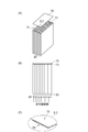
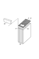
- FIG. 1A is a perspective view showing an example of a light guide plate manufactured by an embodiment of the manufacturing method of the present invention.
- FIG. 1B is an enlarged perspective view showing an end portion of the light guide plate shown in FIG. 2 (A) and 2 (B) are drawings showing an embodiment of the production method of the present invention.
- FIG. 2C is an enlarged perspective view showing the end face of the screen plate shown in FIG.
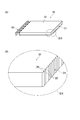
- FIG. 3A is a perspective view showing an example of a light guide plate manufactured by an embodiment of the manufacturing method of the present invention.
- FIG. 3B is an enlarged perspective view showing an end portion of the light guide plate shown in FIG.
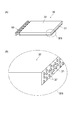
- FIG. 4A is a perspective view showing an example of the light guide plate manufactured by one embodiment of the manufacturing method of the present invention.
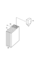
- FIG. 4B is an enlarged perspective view showing an end portion of the light guide plate shown in FIG. 5A to 5D are diagrams showing an embodiment of the production method of the present invention.
- FIG. 6 is a diagram showing an embodiment of the production method of the present invention.
- FIG. 7 is a diagram showing an embodiment of the production method of the present invention.
- the light guide plate original plate 20 is bundled and shaped on the end surface 21 of the light guide plate original plate 20 (see FIGS. 5A to 5D and FIGS. 2A to 2C). ).
- the manufacturing method of this embodiment includes a step of bundling a plurality of light guide plate original plates 20 as shown in FIG. 5C, and a step of bundling the light guide plate original plates 20 as shown in FIGS. At least a step of processing each end face 21.
- a plate obtained by processing the end surface 21 of the light guide plate original plate 20 is a “light guide plate 30”
- a plate before the end surface 21 is processed is a “light guide plate original plate 20”
- a light guide plate original plate having a predetermined size The plate before being cut into 20 is referred to as “light guide plate original plate 10 before cutting”.
- a plate made of a transparent resin is usually used.
- the transparent resin include methacrylic resin (PMMA, etc.), polycarbonate resin, ABS resin (acrylonitrile-styrene-butadiene copolymer resin), MS resin (methyl methacrylate-styrene copolymer resin), polystyrene resin, AS Resin (acrylonitrile-styrene copolymer resin), polyolefin resin (polyethylene, polypropylene, etc.), and cyclic polyolefin are included.
- the following method can be usually used industrially.
- Melt extrusion method Transparent resin material is melt-extruded using an extruder, and at least one surface of a sheet-like material that can be discharged from a die is brought into contact with a roll or a belt to be formed into a sheet shape, and a light guide plate original plate 10 before cutting It is a method of manufacturing.
- Cast polymerization method After mixing a monomer composition containing a monomer component and a polymerization initiator, two glasses are injected into a cell facing each other through a spacer.
- Press molding a method for producing a light guide plate original plate 10 before cutting by molding a transparent resin material into a plate shape using a heating press device.
- a light guide plate original plate obtained by injection molding it may be used for further end face processing.
- the shape imparted to the end surface 21 of the light guide plate original plate 20 is mainly to reduce light leaking from the end portion 31 of the light guide plate 30 or to control the direction of light reflected by the end portion 31 of the light guide plate 30.
- the shape is selected for the purpose.
- an example of processing the end surface 21 of the light guide plate original plate 20 includes shaping the groove 35 on the end surface 21.
- the groove includes a groove 35 in a direction parallel to the surface (outgoing surface) 32 of the light guide plate original plate 20 (see FIGS. 1A and 1B).
- An example of the cross-sectional shape of the convex portion 36 formed by the groove 35 includes a triangular prism having an apex angle of 90 degrees, and the extending direction of the convex portion 36 can be parallel to the emission surface 32.
- the apex angle of the triangular prism is usually in the range of 45 degrees to 120 degrees, and preferably 60 degrees to 100 degrees.
- the side length of the triangular prism is usually in the range of 10 ⁇ m to 1 mm, preferably in the range of 30 ⁇ m to 500 ⁇ m.
- the groove includes a groove in a direction parallel to the thickness direction of the light guide plate original plate 20 (perpendicular to the emission surface 32) (see FIGS. 3A and 3B).
- the example of the cross-sectional shape of the convex portion 36 formed by the groove includes a shape that is a triangular prism having an apex angle of 90 degrees, and the extending direction of the convex portion 36 can be parallel to the thickness direction.
- the apex angle of the triangular prism is usually in the range of 45 degrees to 120 degrees, and preferably 60 degrees to 100 degrees.
- the side length of the triangular prism is usually in the range of 10 ⁇ m to 1 mm, preferably in the range of 30 ⁇ m to 500 ⁇ m.
- the shape of the end face 21 (see FIG. 4A) of the light guide plate 20 is not a two-dimensional linear groove as described above, but a cone, a quadrangular pyramid, a part of a sphere, or the like.
- a three-dimensional structure may be formed, and for example, a conical protrusion 37 as shown in FIG.
- the light guide plate original plate 20 is bundled.
- the following method can be mentioned as a method of bundling the light guide plate original plate 20.
- the light guide plate original plate 20 may be simply stacked (particularly in the case of flat placement). In the case of flat placement, the light guide plate original plate 20 may be pressed by placing a heavy object thereon.
- examples of how to bundle the light guide plate original plate 20 include a method using a vise, a method using a string or a belt, and a method of screwing in a container. Flatness may be ensured by placing a highly rigid metal plate or glass plate on both sides of the outer side (end surface 21 of the light guide plate original plate 20) and sandwiching the bundle of light guide plate original plates 20 between them.
- the thickness after the light guide plate original plate 20 is bundled is usually 10 mm or more, preferably 20 mm or more, more preferably 50 mm or more. As the thickness after the light guide plate original plate 20 is bundled is higher, higher fixability and stability can be obtained, so that highly accurate processing can be performed. However, if the thickness after the light guide plate original plate 20 is bundled exceeds 500 mm, handling becomes difficult.
- the light guide plate original plate 10 before cutting is bundled as shown in FIG.
- the method of bundling the light guide plate original plate 10 before cutting can be the same as the method of bundling the light guide plate original plate 20.
- the step of cutting the light guide plate original plate 20 from the pre-cut light guide plate original plate 10 can be performed using an electric saw or a laser cutter.
- a dotted line in FIG. 5B indicates a position to be cut out. If the thickness of the light guide plate original plate 10 before cutting is thin, it can be performed using a cutting method using a frame-shaped mold.
- the end surface 21 of the light guide plate original plate 20 may be polished before shaping the end surface 21 of the light guide plate original plate 20.
- a polishing method for example, a general sandpaper can be used.
- the sandpaper to be used is usually 400 or more.
- rough polishing may be performed with 320-600 sandpaper, and then final polishing may be performed with 800-1200 sandpaper.
- the shaping of the end surface 21 of the light guide plate original plate 20 can be performed by various methods.
- the shaping method include a photopolymer method (ultraviolet curable resin), a hot embossing method, grinding, cutting, and the like.
- a method for shaping the end face 21 of the light guide plate original plate 20 a method of shaping with an ultraviolet curable resin and a mold can be used.
- the ultraviolet curable resin a commercially available ultraviolet curable resin such as urethane acrylate can be used.
- molds shaped by various methods can be used. Using a steel plate with copper plating, cut with a diamond bite, or using a master mold with a desired shape transferred from the master mold by so-called electroforming. Can do. A shaped film such as a commercially available prism sheet can also be used.
- the curing method is as follows in the case of using an opaque mold such as metal.
- the ultraviolet curable resin 73 is applied to the shaping-side end surface 21 of the light guide plate original plate 20, and the mold 75 is brought into contact with the ultraviolet curable resin 73.
- the metal mold 75 is provided with irregularities 76 on the side where the ultraviolet curable resin 73 is brought into contact.
- ultraviolet rays are irradiated from an end surface 22 opposite to the shaping-side end surface 21 of the light guide plate original plate 20. The irradiated light propagates inside the light guide plate original plate 20 and the ultraviolet curable resin 73 is irradiated with ultraviolet rays.
- the ultraviolet curable resin 73 When the ultraviolet curable resin 73 is irradiated with ultraviolet rays, the ultraviolet curable resin 73 is cured and shaped on the end surface 21 of the light guide plate original plate 20.
- the light guide plate original plate 20 having sufficient transparency with respect to the absorption wavelength of the photoinitiator is required.
- a transparent mold transparent to the absorption wavelength of the photoinitiator
- light may be irradiated from the mold side. Examples of the transparent mold include those in which a shape opposite to the desired uneven shape is imparted to the transparent resin substrate film.
- Other methods for shaping the end surface 21 of the light guide plate original plate 20 include a method of directly forming a groove 83 with a blade 81, hot embossing, and the like, as shown in FIG.
- the end face 21 of the light guide plate original plate 20 As a method of processing the end face 21 of the light guide plate original plate 20, not only shaping processing such as grooving but also printing can be performed.
- the end surface 21 of the light guide plate original plate 20 may be painted white.
- a white plate transparent acrylic resin is passed through the opening through a screen plate 91 having an opening of an appropriate mesh size.
- a method of screen printing by pushing in a filler 93 such as silica, titanium oxide or the like may be used. The pushing of the white ink 93 into the opening is performed by moving the squeegee 95 while the screen plate 91 is pressed.
- the print pattern is a pattern that is appropriately adjusted while taking into consideration optical characteristics, such as a dot pattern whose size and density are adjusted, a line pattern whose line width and line density are adjusted, and a white fill entirely. Can be used.
- the warp during processing is reduced.
- the light guide plate original plate 20 can be stably held. For this reason, it is possible to accurately shape the end surface 21 of the light guide plate original plate 20.
- the step of bundling the light guide plate original plate 20 and the step of shaping the end surface 21 of the light guide plate original plate 20 are performed in a series of operations.
- the process of cutting out the light guide plate original plate 20 from the light guide plate original plate 10 before cutting, the step of polishing the end surface 21 of the light guide plate original plate 20, and the step of shaping the end surface 21 of the light guide plate original plate 20 may be performed in a series of operations. it can. Since the bundles of the light guide plate original plates 20 are not separated during each step (work), it is not necessary to align the positions of the light guide plate original plates 20 again (align the positions of the end faces 21). In addition, work efficiency can be improved. Further, the ultraviolet curable resin 73 can be irradiated with ultraviolet rays regardless of the type of the mold 75. With these actions, a highly accurate groove shape can be produced.
- Example 1 PMMA (polymethyl methacrylate) (“SUMIPEX EXN” manufactured by Sumitomo Chemical Co., Ltd.) is melt kneaded with a single screw extruder having a screw diameter of 40 mm. Next, this molten resin is extruded from a T-die at a resin temperature of 255 ° C. to produce a pre-cut light guide plate 10 having a thickness of 4 mm and a width of 250 mm.
- SUMIPEX EXN polymethyl methacrylate
- the light guide plate original plate 10 before cutting obtained in this way is cut into a size of 200 mm in width and 400 mm in length to manufacture the light guide plate original plate 20.
- 15 light guide plate original plates 20 thus obtained are stacked.
- the four side surfaces including the end surface 21 are polished with a polishing machine (“Pura Beauty 1000” manufactured by Asahi Megaro Co., Ltd.).
- the polished light guide plate original plate 20 is produced.
- the bundle of the light guide plate original plate 20 obtained in this way is installed as shown in FIG. 2A, and the end surface 21 to be shaped is directed upward.
- an ultraviolet curable resin 73 is applied to the upper end surface 21 which is an end surface to be shaped to a thickness of about 30 ⁇ m using a bar coater.
- a die as shown in FIG. 2C (prism groove (pitch 50 ⁇ m, apex angle 90 degrees, extending in parallel to the exit surface) from above the end face 21 to which the ultraviolet curable resin 73 is applied.
- a metal mold having 75 is applied.
- the ultraviolet curable resin 73 applied to the upper end surface 21 is cured by irradiating ultraviolet rays from the end surface 22 on the side opposite to the shaping end surface (see FIG. 2B).
- the end face 21 is shaped by curing the ultraviolet curable resin 73, and for example, the end portion 31 of the light guide plate 30 having a prism structure as shown in FIG. 1B is obtained.
Landscapes
- Physics & Mathematics (AREA)
- General Physics & Mathematics (AREA)
- Optics & Photonics (AREA)
- Engineering & Computer Science (AREA)
- Manufacturing & Machinery (AREA)
- Planar Illumination Modules (AREA)
- Light Guides In General And Applications Therefor (AREA)
Abstract
導光板の製造方法は、複数の導光板原板(20)を束ねる工程と、束ねられた導光板原板(20)の各々の端面(21)に加工を施す工程とを有している。 また、導光板の製造方法は、複数の切出前導光板原板(10)を束ねる工程と、束ねられた状態の切出前導光板原板(10)の各々を所定の大きさの導光板原板(20)に切り出す工程と、束ねられた導光板原板20の各々の端面(21)に加工を施す工程とを有する。
Description
本発明は、液晶テレビ、液晶モニタ、パーソナルコンピュータなどに用いられる液晶表示装置用および照明装置用のバックライトに用いる導光板の製造方法に関する。
液晶表示装置や照明装置等のバックライトとしては、例えば導光板の側方(「端部」または「エッジ」と称する。)にLED光源等の光源を配置し、該LED光源からの光を、全反射により導光板内部を導光させつつ、導光板背面に形成されたドットパターンやプリズム部等により反射させて導光板前面から光を均一に出射できるように構成したものが知られている(例えば、特許文献1参照。)。
このようなバックライト用の導光板の製造方法としては、バックライトの輝度向上や輝度均一性の向上を目的として、導光板原板の端面をプリズム形状などの所望の形状に加工して導光板を製造することが提案されている。
加工して製造する方法としては、端部に所望の形状が形成された導光板を射出成形を用いて製造する方法(例えば、特許文献2参照。)や、導光板原板を1枚づつ、回転させたカッタ刃を用いてその端面を加工して製造する方法(例えば、特許文献3参照。)が提案されている。
しかしながら、射出成形は金型が高価であり経済的でない。また、導光板原板1枚毎にその端面を回転させたカッタ刃を用いて加工する製造方法の場合は、導光板の反りやうねりなどにより、位置決め精度が悪く、精度が高い加工は困難であった。
そこで本発明の目的は、導光板原板の端面に精度の高い加工を施すことができる導光板の製造方法を提供することにある。
本発明はかかる技術的背景に鑑みてなされたものであって、本発明者は、導光板の製造方法について鋭意検討した結果、本発明を完成するに至った。
本発明に係る導光板の製造方法は、複数の導光板原板を束ねる工程と、束ねられた導光板原板の各々の端面に加工を施す工程と、を有する。
本発明に係る製造方法は、束ねられた導光板原板の各々の端面に研磨を施す工程を更に有し、導光板原板を束ねる工程、端面に研磨を施す工程、及び端面に加工を施す工程を一連の作業で行ってもよい。
本発明に係る製造方法は、複数の切出前導光板原板を束ねる工程と、束ねられた状態の切出前導光板原板の各々を所定の大きさの導光板原板に切り出す工程と、束ねられた導光板原板の各々の端面に加工を施す工程と、を有している。
本発明に係る製造方法は、束ねられた導光板原板の各々の端面に研磨を施す工程を更に有し、切出前導光板原板を束ねる工程、導光板原板に切り出す工程、端面に研磨を施す工程、及び端面に加工を施す工程を一連の作業で行ってもよい。
本発明に係る製造方法では、端面に加工を施す工程において、束ねられた導光板原板の各々の端面を一括して加工してもよい。
本発明に係る製造方法では、端面に加工を施す工程における加工とは、端面への溝の賦形であり、溝は、導光板原板の出射面に平行な方向の溝であってもよい。
本発明に係る製造方法では、端面に加工を施す工程における加工とは、端面への溝の賦形であり、溝は、導光板原板の厚み方向に平行な方向の溝であってもよい。
本発明に係る製造方法では、端面に加工を施す工程における加工とは、端面への凹凸部の賦形であり、凹凸部は、複数の突起を有する金型を用いて形成されてもよい。
本発明に係る製造方法では、端面への加工は、金型に接触された状態の紫外線硬化樹脂に紫外線を照射し、該紫外線硬化樹脂を硬化させることにより行われてもよい。
本発明に係る製造方法では、紫外線の照射は、加工を施す端面とは反対側の端面から導光板原板を介して照射されてもよい。
本発明に係る製造方法では、端面に加工を施す工程における加工とは、端面への印刷により模様をつけることであってもよい。
本発明に係る製造方法は、束ねられた導光板原板の各々の端面に研磨を施す工程を更に有し、導光板原板を束ねる工程、端面に研磨を施す工程、及び端面に加工を施す工程を一連の作業で行ってもよい。
本発明に係る製造方法は、複数の切出前導光板原板を束ねる工程と、束ねられた状態の切出前導光板原板の各々を所定の大きさの導光板原板に切り出す工程と、束ねられた導光板原板の各々の端面に加工を施す工程と、を有している。
本発明に係る製造方法は、束ねられた導光板原板の各々の端面に研磨を施す工程を更に有し、切出前導光板原板を束ねる工程、導光板原板に切り出す工程、端面に研磨を施す工程、及び端面に加工を施す工程を一連の作業で行ってもよい。
本発明に係る製造方法では、端面に加工を施す工程において、束ねられた導光板原板の各々の端面を一括して加工してもよい。
本発明に係る製造方法では、端面に加工を施す工程における加工とは、端面への溝の賦形であり、溝は、導光板原板の出射面に平行な方向の溝であってもよい。
本発明に係る製造方法では、端面に加工を施す工程における加工とは、端面への溝の賦形であり、溝は、導光板原板の厚み方向に平行な方向の溝であってもよい。
本発明に係る製造方法では、端面に加工を施す工程における加工とは、端面への凹凸部の賦形であり、凹凸部は、複数の突起を有する金型を用いて形成されてもよい。
本発明に係る製造方法では、端面への加工は、金型に接触された状態の紫外線硬化樹脂に紫外線を照射し、該紫外線硬化樹脂を硬化させることにより行われてもよい。
本発明に係る製造方法では、紫外線の照射は、加工を施す端面とは反対側の端面から導光板原板を介して照射されてもよい。
本発明に係る製造方法では、端面に加工を施す工程における加工とは、端面への印刷により模様をつけることであってもよい。
本発明の製造方法によれば、導光板が薄く、反りを発生しやすい場合や、もともと若干の反りを有した導光板であっても、加工時の反りを低減することができ、さらには、安定して導光板を保持できるようになるため、精度良く賦形加工をすることができる。
本実施形態における導光板の製造方法は、導光板原板20を束ねて導光板原板20の端面21に賦形する(図5(A)~(D)、図2(A)~(C)参照)。
以下、本発明の一実施形態について詳細に説明する。本実施形態の製造方法は、図5(C)に示すように、複数の導光板原板20を束ねる工程と、図2(A)~(C)に示すように、束ねた導光板原板20の各々の端面21に加工を施す工程と、を少なくとも備える。以下、工程毎に順に説明する。
導光板原板20の端面21に加工を施して得られた板を「導光板30」、端面21に加工を施す前の板を「導光板原板20」、また、所定の大きさの導光板原板20に切り出す前の板を「切出前導光板原板10」と称することとする。
導光板原板20の端面21に加工を施して得られた板を「導光板30」、端面21に加工を施す前の板を「導光板原板20」、また、所定の大きさの導光板原板20に切り出す前の板を「切出前導光板原板10」と称することとする。
本実施形態の製造方法により製造される導光板30の加工前の導光板原板20としては、通常は、板状に成形された透明樹脂からなるものが用いられる。前記透明樹脂の例には、メタクリル樹脂(PMMA等)、ポリカーボネート樹脂、ABS樹脂(アクリロニトリル-スチレン-ブタジエン共重合体樹脂)、MS樹脂(メタクリル酸メチル-スチレン共重合体樹脂)、ポリスチレン樹脂、AS樹脂(アクリロニトリル-スチレン共重合体樹脂)、ポリオレフィン樹脂(ポリエチレン、ポリプロピレン等)、環状ポリオレフィンが含まれる。
前記樹脂を板状に成形して切出前導光板原板10を製造する方法としては、次の方法が工業的に通常用いることができる。
溶融押出法;透明樹脂材料を、押出機を用いて溶融押出しし、ダイから吐出され得られるシート状物の少なくとも片面をロール又はベルトに接触させてシート状に成形して切出前導光板原板10を製造する方法である。
キャスト重合法;単量体成分、および重合開始剤を含有してなる単量体組成物を混合した後に、スペーサーを介して二枚のガラスを向かい合わせたセル内に注入する。その後に、加熱あるいは紫外線照射などの手法により開始剤を活性化させることで重合させてシート状の成形体を得て切出前導光板原板10を製造する方法である。
プレス成形;加熱プレス装置を用いて透明樹脂材料を板状に成形して切出前導光板原板10を製造する方法である。当然、射出成形で得られた導光板原板として、さらなる端面の加工に用いられても構わない。
溶融押出法;透明樹脂材料を、押出機を用いて溶融押出しし、ダイから吐出され得られるシート状物の少なくとも片面をロール又はベルトに接触させてシート状に成形して切出前導光板原板10を製造する方法である。
キャスト重合法;単量体成分、および重合開始剤を含有してなる単量体組成物を混合した後に、スペーサーを介して二枚のガラスを向かい合わせたセル内に注入する。その後に、加熱あるいは紫外線照射などの手法により開始剤を活性化させることで重合させてシート状の成形体を得て切出前導光板原板10を製造する方法である。
プレス成形;加熱プレス装置を用いて透明樹脂材料を板状に成形して切出前導光板原板10を製造する方法である。当然、射出成形で得られた導光板原板として、さらなる端面の加工に用いられても構わない。
導光板原板20の端面21に付与される形状としては、主に、導光板30の端部31から漏れる光を低減する、あるいは、導光板30の端部31で反射した光の向きを制御するという目的で形状が選ばれる。
例えば、導光板原板20の端面21への加工の例には、端面21への溝35の賦形が含まれる。溝には、導光板原板20の面(出射面)32に平行な方向の溝35が含まれる(図1(A)及び(B)参照)。溝35により形成された凸部36の断面形状の例には、頂角90度の三角プリズムが含まれ、凸部36の延在方向を出射面32に平行とすることができる。導光板30の端部31をこの形状にすることにより端部31からの光の漏れを抑制することができる。該三角プリズムの頂角は、通常は45度~120度の範囲であり、60度~100度が好ましい。該三角プリズムの辺の長さは、通常は10μm~1mmの範囲であり、30μm~500μmの範囲が好ましい。
また例えば、溝には、導光板原板20の厚み方向に平行(出射面32に垂直)な方向の溝が含まれる(図3(A)及び(B)参照)。溝により形成された凸部36の断面形状の例には、頂角90度の三角プリズムである形状が含まれ、凸部36の延在方向を厚み方向に平行とすることができる。導光板30の端部31をこの形状にすることにより面内の広がりを調整することができる。プリズムの頂角および溝の底部は丸みを有していてもよい。該三角プリズムの頂角は、通常は45度~120度の範囲であり、60度~100度が好ましい。該三角プリズムの辺の長さは、通常は10μm~1mmの範囲であり、30μm~500μmの範囲が好ましい。
また、導光板原板20の端面21(図4(A)参照)への賦形は、上記で説明したような二次元的な線状の溝でなく、円錐、四角錐、球の一部など、三次元的な構造(凹凸部)の形成でもよく、例えば、図4(B)に示すような円錐状の突起37であってもよい。
以下、本実施形態における各工程を説明する。
まず、図5(C)に示すように導光板原板20を束ねる。導光板原板20の束ね方としては次の方法を挙げることができる。単に導光板原板20を重ねるだけでもよい(特に平置きの場合)し、平置きの場合は、導光板原板20の上から重量物を載せることで押さえつけてもよい。また、導光板原板20の束ね方の例には、万力を使う方法、ひも、あるいは、ベルトを用いる方法、容器に入れてねじ止めする方法が含まれる。外側(導光板原板20の端面21)の両側に剛性の高い金属板やガラス板など平面度の高いものを置き、導光板原板20の束を挟み込むことで平坦性を確保してもよい。
まず、図5(C)に示すように導光板原板20を束ねる。導光板原板20の束ね方としては次の方法を挙げることができる。単に導光板原板20を重ねるだけでもよい(特に平置きの場合)し、平置きの場合は、導光板原板20の上から重量物を載せることで押さえつけてもよい。また、導光板原板20の束ね方の例には、万力を使う方法、ひも、あるいは、ベルトを用いる方法、容器に入れてねじ止めする方法が含まれる。外側(導光板原板20の端面21)の両側に剛性の高い金属板やガラス板など平面度の高いものを置き、導光板原板20の束を挟み込むことで平坦性を確保してもよい。
導光板原板20を束ねた後の厚みは、通常は10mm以上であり、好ましくは20mm以上であり、より好ましくは50mm以上である。導光板原板20を束ねた後の厚みは、厚い方が、より高い固定性、安定性が得られるため、精度の高い加工が出来る。しかし、導光板原板20を束ねた後の厚みが500mmを超えると取り扱いが困難になる。
切出前導光板原板10から導光板30を製造する際には、まず、図5(A)に示すように、切出前導光板原板10を束ねる。切出前導光板原板10の束ね方は、導光板原板20の束ね方と同様の方法とすることができる。次に、図5(B)に示すように、切出前導光板原板10から導光板原板20を切り出す工程は、電動式のこぎり、レーザーカッターを用いて行うことができる。図5(B)の点線は、切り出す位置を示している。切出前導光板原板10の厚みが薄ければ、枠状の金型を用いた断裁方式を用いて行うことができる。
導光板原板20の端面21に賦形する前に、導光板原板20の端面21を研磨してもよい。研磨の方法としては、例えば一般的なサンドペーパーを用いることが出来る。用いるサンドペーパーは、通常は400番以上のものが適当である。導光板原板20の端面21の粗さにより、まず320番~600番のサンドペーパーで粗研磨を行い、その後で800番~1200番のサンドペーパーで仕上げ研磨を行ってもよい。
導光板原板20の端面21に、より精度の高い加工を施すためには、高い平滑度が得られる方法が望ましい。この方法には、研磨材を用いた研磨やバフ研磨などがあり、例えば、図5(D)に示すように、ダイヤモンドの刃物を用いた導光板用端面仕上機70を使用することが好ましい。これにより、簡便な方法で、良好な端面21が、効率よく得られる。
導光板原板20の端面21への賦形は種々の方法で行うことができる。賦形方法の例には、フォトポリマー法(紫外線硬化樹脂)、ホットエンボシング法、研削、切削等が含まれる。
導光板原板20の端面21への賦形の方法として、紫外線硬化樹脂と金型とで賦形する方法を用いることができる。
紫外線硬化樹脂としては、ウレタンアクリレートなど、市販の紫外線硬化樹脂を用いることができる。
紫外線硬化樹脂としては、ウレタンアクリレートなど、市販の紫外線硬化樹脂を用いることができる。
金型の種類は、種々の方法で賦形された一般の金型を用いることができる。鋼板の表面に銅メッキを施したものを、ダイヤモンドバイトで切削したものや、所望の形状を有するマスター金型から、いわゆる、電鋳加工法によりマスター金型の形状を転写したものなどを用いることができる。また、市販のプリズムシートなど賦形フィルムを用いることもできる。
硬化の方法(光の当て方)は、金属などの不透明な金型を用いる場合においては以下のとおりである。まず、図2(A)に示すように、導光板原板20の賦形側の端面21に紫外線硬化樹脂73を塗布し、金型75を紫外線硬化樹脂73に接触させる。金型75は、図2(C)に示すように、紫外線硬化樹脂73を接触させる側に凹凸76が形成されている。次に、図2(B)に示すように、導光板原板20の賦形側の端面21とは反対側の端面22から紫外線を照射する。照射された光は導光板原板20の内部を伝搬し、紫外線硬化樹脂73に紫外線が照射される。紫外線硬化樹脂73に紫外線が照射されると、紫外線硬化樹脂73が硬化して、導光板原板20の端面21に賦形される。光開始剤の吸収波長に対して、十分な透過性を有する導光板原板20が必要である。透明(光開始剤の吸収波長に対して透明)な金型を用いる場合は、金型側から光を照射すればよい。透明な金型の例には、透明樹脂基材フィルムに所望の凹凸形状とは逆の形状が付与されているものが挙げられる。
導光板原板20の端面21に賦形させるその他の方法には、図6に示すように、刃物81で直接、溝83を入れる方法や、ホットエンボッシングなどが含まれる。
導光板原板20の端面21に加工を施す方法には、溝加工などの賦形加工だけではなく、印刷を施すこともできる。導光板30の端部31から漏れる光を低減する目的のため、例えば、導光板原板20の端面21を白色に塗装してもよい。また、白色塗料で点状、線状、あるいは、帯状の模様を付与してもよい。
導光板原板20の端面21に印刷を施す場合には、図7に示すように、例えば、適当なメッシュサイズの開口部を有するスクリーン版91を通して、その開口部に白色インク(透明なアクリル系樹脂にシリカ、酸化チタンなどのフィラーを添加したもの)93を押し込むことによってスクリーン印刷する方法を用いてもよい。そして、この開口部への白色インク93の押し込みは、スキージ95をスクリーン版91に押圧させた状態で移動させることによって行われる。
印刷パターンには、大きさや密度などが調整された点状パターン、線幅や線密度などが調整された線状パターン、及び全面白色塗りつぶしなど、光学特性を考慮しながら、適宜、調整されたパターンを用いることができる。
本実施形態の導光板の製造方法では、厚みが薄く、反りを発生しやすい導光板原板20や、もともと若干の反りを有した導光板原板20であっても、加工時の反りを低減することができ、さらには、安定して導光板原板20を保持できるようになる。このため、導光板原板20の端面21に精度良く、賦形する加工を行うことができる。
また、本実施形態の導光板の製造方法では、導光板原板20を束ねる工程、及び導光板原板20の端面21へ賦形する工程を一連の作業で行っている。また、切出前導光板原板10から導光板原板20を切り出す工程、導光板原板20の端面21を研磨する工程、及び導光板原板20の端面21へ賦形する工程を一連の作業で行うこともできる。各工程(作業)の間で、導光板原板20の束をばらばらにしないことで、再度、導光板原板20同士の位置を合わせる(端面21の位置を揃える)必要がないため、加工精度を上げることができ、さらに、作業効率も向上する。また、金型75の種類によらず、紫外線硬化樹脂73に紫外線を照射することができる。これらの作用により、精度の高い溝形状を作製することができる。
以下に実施例を示して本発明をさらに詳細に説明するが、本発明は以下に示す実施例に限定されるものではない。
(実施例1)
PMMA(ポリメチルメタアクリレート)(住友化学株式会社製「スミペックスEXN」)をスクリュー径40mmの1軸押出機で溶融混練する。次に、この溶融樹脂を樹脂温度255℃でTダイから押出し、厚さ4mm、幅250mmの切出前導光板原板10を製造する。
PMMA(ポリメチルメタアクリレート)(住友化学株式会社製「スミペックスEXN」)をスクリュー径40mmの1軸押出機で溶融混練する。次に、この溶融樹脂を樹脂温度255℃でTダイから押出し、厚さ4mm、幅250mmの切出前導光板原板10を製造する。
このようにして得られる切出前導光板原板10を幅200mm、長さ400mmの大きさに切り出し加工して導光板原板20を製造する。次に、このようにして得られる導光板原板20を15枚重ねる。次に、この重ねられた導光板原板20を万力で固定した状態で、4つの側面(端面21を含む)を研磨機(朝日メガロ社製「プラビューティー1000」)で研磨して、側面が研磨された導光板原板20を作製する。
このようにして得られる導光板原板20の束を、図2(A)に示すように設置し、賦形する端面21を上に向ける。次に、賦形する端面である上側の端面21に、バーコーターを用いて紫外線硬化樹脂73を、約30μmの厚みに塗布する。
次に、紫外線硬化樹脂73が塗布された端面21の上から、図2(C)に示すような金型(プリズム溝(ピッチ50μm、頂角90度、出射面に対して平行に延在)を有する金属金型)75を当てる。次に、賦形する端面の反対側(図2(B)参照)の端面22から紫外線を照射することで、上側端面21に塗布された紫外線硬化樹脂73を硬化させる。金型75を取り除くと、紫外線硬化樹脂73が硬化することにより端面21が賦形され、例えば図1(B)に示すようなプリズム構造を有する導光板30の端部31が得られる。
以上、本発明の一実施形態及び実施例について説明したが、本発明は上記実施形態及び実施例に限定されるものではない。本発明は、発明の趣旨を逸脱しない範囲で種々の変更が可能である。
10…切出前導光板原板、20…導光板原板、21…端面、22…端面、30…導光板、31…端部、32…出射面、35…溝、36…凸部、37…突起、70…導光板用端面仕上機、73…紫外線硬化樹脂、75…金型、76…凹凸、81…刃物、83…溝、91…スクリーン版、93…白色インク、95…スキージ。
Claims (11)
- 複数の導光板原板を束ねる工程と、
束ねられた前記導光板原板の各々の端面に加工を施す工程と、
を有する導光板の製造方法。 - 束ねられた前記導光板原板の各々の端面に研磨を施す工程を更に有し、
前記導光板原板を束ねる工程、前記端面に研磨を施す工程、及び前記端面に加工を施す工程を一連の作業で行う、
請求項1記載の製造方法。 - 複数の切出前導光板原板を束ねる工程と、
束ねられた状態の前記切出前導光板原板の各々を所定の大きさの導光板原板に切り出す工程と、
束ねられた前記導光板原板の各々の端面に加工を施す工程と、
を有する導光板の製造方法。 - 束ねられた前記導光板原板の各々の端面に研磨を施す工程を更に有し、
前記切出前導光板原板を束ねる工程、前記導光板原板に切り出す工程、前記端面に研磨を施す工程、及び前記端面に加工を施す工程を一連の作業で行う、
請求項3記載の製造方法。 - 前記端面に加工を施す工程では、前記束ねられた導光板原板の各々の端面を一括して加工する、
請求項1~4のいずれか一つに記載の製造方法。 - 前記端面に加工を施す工程における前記加工とは、前記端面への溝の賦形であり、
前記溝は、前記導光板原板の出射面に平行な方向の溝である、
請求項1~5のいずれか一つに記載の製造方法。 - 前記端面に加工を施す工程における前記加工とは、前記端面への溝の賦形であり、
前記溝は、前記導光板原板の厚み方向に平行な方向の溝である、
請求項1~5のいずれか一つに記載の製造方法。 - 前記端面に加工を施す工程における前記加工とは、前記端面への凹凸部の賦形であり、
前記凹凸部は、複数の突起を有する金型を用いて形成される、
請求項1~5のいずれか一つに記載の製造方法。 - 前記端面への加工は、金型に接触された状態の紫外線硬化樹脂に紫外線を照射し、該紫外線硬化樹脂を硬化させることより行われる、
請求項1~8のいずれか一つに記載の製造方法。 - 前記紫外線の照射は、加工を施す前記端面とは反対側の端面から前記導光板原板を介して照射される、
請求項9記載の製造方法。 - 前記端面に加工を施す工程における前記加工とは、前記端面への印刷により模様をつけることである、
請求項1~5のいずれか一つに記載の製造方法。
Applications Claiming Priority (2)
| Application Number | Priority Date | Filing Date | Title |
|---|---|---|---|
| JP2011-103434 | 2011-05-06 | ||
| JP2011103434A JP2012234083A (ja) | 2011-05-06 | 2011-05-06 | 導光板の製造方法 |
Publications (1)
| Publication Number | Publication Date |
|---|---|
| WO2012153650A1 true WO2012153650A1 (ja) | 2012-11-15 |
Family
ID=47139134
Family Applications (1)
| Application Number | Title | Priority Date | Filing Date |
|---|---|---|---|
| PCT/JP2012/061259 Ceased WO2012153650A1 (ja) | 2011-05-06 | 2012-04-26 | 導光板の製造方法 |
Country Status (2)
| Country | Link |
|---|---|
| JP (1) | JP2012234083A (ja) |
| WO (1) | WO2012153650A1 (ja) |
Families Citing this family (1)
| Publication number | Priority date | Publication date | Assignee | Title |
|---|---|---|---|---|
| JP6590320B2 (ja) * | 2016-02-19 | 2019-10-16 | パナソニックIpマネジメント株式会社 | 導光板、導光板を用いた照明装置及び導光板の製造方法 |
Citations (6)
| Publication number | Priority date | Publication date | Assignee | Title |
|---|---|---|---|---|
| JPS62100903A (ja) * | 1985-10-26 | 1987-05-11 | 三菱レイヨン株式会社 | 光拡散器用導光体及びその製造方法 |
| JP2002163914A (ja) * | 2000-11-24 | 2002-06-07 | Nec Corp | 照明装置と該照明装置を用いた液晶表示装置及びその製造方法 |
| WO2009025103A1 (ja) * | 2007-08-22 | 2009-02-26 | Mitsubishi Rayon Co., Ltd. | 面光源装置 |
| JP2010056089A (ja) * | 2008-08-28 | 2010-03-11 | Sharp Corp | 反射率の高い導光体、並びに、反射率の高い導光体を有する照明装置およびディスプレイ装置 |
| JP2010080239A (ja) * | 2008-09-25 | 2010-04-08 | Sharp Corp | 導光板およびその製造方法、ならびにその導光板を用いた面発光装置および携帯電話機 |
| JP2011044324A (ja) * | 2009-08-21 | 2011-03-03 | Sumitomo Electric Ind Ltd | 導光板、プリント配線板、キーモジュール、電子機器 |
-
2011
- 2011-05-06 JP JP2011103434A patent/JP2012234083A/ja not_active Withdrawn
-
2012
- 2012-04-26 WO PCT/JP2012/061259 patent/WO2012153650A1/ja not_active Ceased
Patent Citations (6)
| Publication number | Priority date | Publication date | Assignee | Title |
|---|---|---|---|---|
| JPS62100903A (ja) * | 1985-10-26 | 1987-05-11 | 三菱レイヨン株式会社 | 光拡散器用導光体及びその製造方法 |
| JP2002163914A (ja) * | 2000-11-24 | 2002-06-07 | Nec Corp | 照明装置と該照明装置を用いた液晶表示装置及びその製造方法 |
| WO2009025103A1 (ja) * | 2007-08-22 | 2009-02-26 | Mitsubishi Rayon Co., Ltd. | 面光源装置 |
| JP2010056089A (ja) * | 2008-08-28 | 2010-03-11 | Sharp Corp | 反射率の高い導光体、並びに、反射率の高い導光体を有する照明装置およびディスプレイ装置 |
| JP2010080239A (ja) * | 2008-09-25 | 2010-04-08 | Sharp Corp | 導光板およびその製造方法、ならびにその導光板を用いた面発光装置および携帯電話機 |
| JP2011044324A (ja) * | 2009-08-21 | 2011-03-03 | Sumitomo Electric Ind Ltd | 導光板、プリント配線板、キーモジュール、電子機器 |
Also Published As
| Publication number | Publication date |
|---|---|
| JP2012234083A (ja) | 2012-11-29 |
Similar Documents
| Publication | Publication Date | Title |
|---|---|---|
| CN100380148C (zh) | 光学膜及使用了它的面光源装置 | |
| US9776360B2 (en) | Transfer printing apparatus and manufacturing method of light guiding film | |
| CN101498859A (zh) | 多功能光学薄板及其制造方法 | |
| JP2016115666A (ja) | バックライトユニット及びその製造方法 | |
| US20150022761A1 (en) | Light guide plate transfer molding method, light guide plate, and planar light source apparatus | |
| JP7030097B2 (ja) | 立体像結像装置の製造方法及び立体像結像装置 | |
| JP4277536B2 (ja) | 光学部品及びその製造方法並びに画像投影スクリーン | |
| JP5957865B2 (ja) | 賦型シートの製造方法、樹脂被覆賦型シートの製造方法及び光学シートの製造方法 | |
| JP5724527B2 (ja) | 導光板積層体およびその製造方法 | |
| TWI374315B (ja) | ||
| JP2007066699A (ja) | 導光板及び導光板の製造方法 | |
| JP5098576B2 (ja) | 光学シート、バックライトユニット及びディスプレイ装置 | |
| WO2012153650A1 (ja) | 導光板の製造方法 | |
| US20110117331A1 (en) | Method for manufacturing an optical film | |
| WO2014014197A1 (ko) | 도광판, 이의 제조 방법, 이를 포함하는 백라이트유닛 및 이를 포함하는 액정표시장치 | |
| TWI551902B (zh) | 光學膜片及應用其之顯示裝置 | |
| JP2017045060A (ja) | 光学シート、面光源装置、映像源ユニット、表示装置、及び光学シートの製造方法。 | |
| JP2004188604A (ja) | 光学的立体造形装置 | |
| CN102879855A (zh) | 导光板及其制造方法 | |
| CN101290432A (zh) | 组合透镜部件、照明装置及液晶显示装置 | |
| KR20130118160A (ko) | 액정표시장치용 세레이션 도광판 및 이를 이용한 백라이트 유닛 | |
| JP6229263B2 (ja) | 面光源装置用導光体の製造方法 | |
| CN101634776B (zh) | 微结构模具的制造方法及用该模具制造光学膜片的方法 | |
| JP2016090945A (ja) | 光学部材、光学部材の製造方法、面光源装置、映像源ユニット、及び液晶表示装置 | |
| JPH10253831A (ja) | 導光板及びその製造方法 |
Legal Events
| Date | Code | Title | Description |
|---|---|---|---|
| 121 | Ep: the epo has been informed by wipo that ep was designated in this application |
Ref document number: 12782003 Country of ref document: EP Kind code of ref document: A1 |
|
| NENP | Non-entry into the national phase |
Ref country code: DE |
|
| 122 | Ep: pct application non-entry in european phase |
Ref document number: 12782003 Country of ref document: EP Kind code of ref document: A1 |