WO2012153460A1 - Dispositif d'aspiration pour aspirateur électrique - Google Patents
Dispositif d'aspiration pour aspirateur électrique Download PDFInfo
- Publication number
- WO2012153460A1 WO2012153460A1 PCT/JP2012/002437 JP2012002437W WO2012153460A1 WO 2012153460 A1 WO2012153460 A1 WO 2012153460A1 JP 2012002437 W JP2012002437 W JP 2012002437W WO 2012153460 A1 WO2012153460 A1 WO 2012153460A1
- Authority
- WO
- WIPO (PCT)
- Prior art keywords
- suction tool
- suction
- vacuum cleaner
- protrusion
- auxiliary
- Prior art date
Links
Images


Classifications
-
- A—HUMAN NECESSITIES
- A47—FURNITURE; DOMESTIC ARTICLES OR APPLIANCES; COFFEE MILLS; SPICE MILLS; SUCTION CLEANERS IN GENERAL
- A47L—DOMESTIC WASHING OR CLEANING; SUCTION CLEANERS IN GENERAL
- A47L5/00—Structural features of suction cleaners
- A47L5/12—Structural features of suction cleaners with power-driven air-pumps or air-compressors, e.g. driven by motor vehicle engine vacuum
- A47L5/22—Structural features of suction cleaners with power-driven air-pumps or air-compressors, e.g. driven by motor vehicle engine vacuum with rotary fans
- A47L5/28—Suction cleaners with handles and nozzles fixed on the casings, e.g. wheeled suction cleaners with steering handle
- A47L5/32—Suction cleaners with handles and nozzles fixed on the casings, e.g. wheeled suction cleaners with steering handle with means for connecting a hose
-
- A—HUMAN NECESSITIES
- A47—FURNITURE; DOMESTIC ARTICLES OR APPLIANCES; COFFEE MILLS; SPICE MILLS; SUCTION CLEANERS IN GENERAL
- A47L—DOMESTIC WASHING OR CLEANING; SUCTION CLEANERS IN GENERAL
- A47L9/00—Details or accessories of suction cleaners, e.g. mechanical means for controlling the suction or for effecting pulsating action; Storing devices specially adapted to suction cleaners or parts thereof; Carrying-vehicles specially adapted for suction cleaners
- A47L9/02—Nozzles
- A47L9/04—Nozzles with driven brushes or agitators
- A47L9/0405—Driving means for the brushes or agitators
- A47L9/0416—Driving means for the brushes or agitators driven by fluid pressure, e.g. by means of an air turbine
-
- A—HUMAN NECESSITIES
- A47—FURNITURE; DOMESTIC ARTICLES OR APPLIANCES; COFFEE MILLS; SPICE MILLS; SUCTION CLEANERS IN GENERAL
- A47L—DOMESTIC WASHING OR CLEANING; SUCTION CLEANERS IN GENERAL
- A47L9/00—Details or accessories of suction cleaners, e.g. mechanical means for controlling the suction or for effecting pulsating action; Storing devices specially adapted to suction cleaners or parts thereof; Carrying-vehicles specially adapted for suction cleaners
- A47L9/02—Nozzles
- A47L9/04—Nozzles with driven brushes or agitators
- A47L9/0461—Dust-loosening tools, e.g. agitators, brushes
- A47L9/0466—Rotating tools
- A47L9/0477—Rolls
Definitions
- the present invention relates to a vacuum cleaner suction tool.
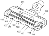
- FIG. 12 is a perspective view showing a suction body 101 of a conventional electric vacuum cleaner from above.
- a conventional vacuum cleaner suction tool 120 as shown in FIG. 12 includes a suction body 101, a concave channel 102, and a brush 103.
- the vacuum cleaner suction tool 120 cleans the surface to be cleaned by the suction airflow generated by the electric blower.
- a plurality of concave flow channels 102 are provided on the bottom surface of the suction body 101.
- the concave flow channel 102 is provided so as to communicate the front side of the suction body 101 and the bottom opening of the suction body 101.
- the brush 103 is provided substantially at the center of the width of each concave channel 102.
- Such a conventional vacuum cleaner suction tool 120 collects dust by sucking air from the front of the mouthpiece 101 to the dust in the corner of the room or near the wall.
- the present invention provides a suction tool for a vacuum cleaner that can efficiently collect dust even for dust that has entered a very small gap, such as between a seat portion such as a sofa and a backrest portion. .
- the vacuum cleaner suction tool of the present invention includes a suction tool main body, a suction tool main body, a suction chamber having an opening below the suction tool main body, and an auxiliary suction port provided in an outer shell of the suction tool main body. It has.
- the auxiliary suction port has a protrusion at the lower front portion of the auxiliary suction port, and a gap is provided between the front end of the bottom surface of the protrusion and the surface to be cleaned.
- the vacuum cleaner suction tool of the present invention it is possible to efficiently collect dust even when the dust enters between the seat and backrest of the sofa or the like.
- FIG. 1 is the perspective view which looked at the vertical vacuum cleaner equipped with the suction tool for vacuum cleaners in the 1st Embodiment of this invention from the front side.
- FIG. 2 is the perspective view which looked at the vertical vacuum cleaner equipped with the suction tool for vacuum cleaners in the same embodiment from the back side.
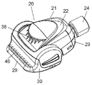
- FIG. 3 is a perspective view of the vacuum cleaner suction tool according to the first embodiment and the fourth embodiment of the present invention as seen from above.
- FIG. 4 is the perspective view which looked at the vacuum cleaner suction tool in the 1st Embodiment of this invention and 2nd Embodiment from the downward direction.
- FIG. 1 is the perspective view which looked at the vertical vacuum cleaner equipped with the suction tool for vacuum cleaners in the 1st Embodiment of this invention from the front side.
- FIG. 2 is the perspective view which looked at the vertical vacuum cleaner equipped with the suction tool for vacuum cleaners in the same embodiment from the back side.
- FIG. 3 is a perspective view of the vacuum cleaner suction tool according to the first embodiment and
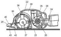
- FIG. 5 is the top view which looked at the internal structure of the state which removed the upper main-body part of the vacuum cleaner suction tool in the 1st Embodiment of this invention from the upper direction.
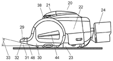
- FIG. 6 is a side view of the vacuum cleaner suction tool according to the first embodiment of the present invention.
- FIG. 7 is a front view showing the vacuum cleaner suction tool according to the first embodiment and the third embodiment of the present invention.
- FIG. 8 is sectional drawing which looked at the internal structure of the vacuum cleaner suction tool in the 1st Embodiment of this invention and 2nd Embodiment from the side.
- FIG. 9 is a side view which shows the state which inserts the protrusion part of an auxiliary
- FIG. 10 is a perspective view which shows the suction tool main body of the suction tool for vacuum cleaners in the 3rd Embodiment and 4th Embodiment of this invention from upper direction.
- FIG. 11 is a perspective view which shows the auxiliary
- FIG. 12 is a perspective view showing a suction body of a conventional electric vacuum cleaner from above.
- FIG. 1 is a perspective view of a vertical vacuum cleaner equipped with a vacuum cleaner suction tool 20 according to the first embodiment of the present invention as seen from the front side.
- FIG. 2 is the perspective view which looked at the vertical vacuum cleaner equipped with the suction tool 20 for the vacuum cleaner from the back side.
- the cleaner body 4 includes a dust collection chamber 5 and a fan motor (not shown).
- a floor nozzle body 7 is connected to the lower part of the cleaner body 4.
- the floor nozzle body 7 has a suction port 6 and a rotating brush (not shown).
- the suction port 6 sucks dust on the floor.
- the rotating brush is rotated by a drive motor (not shown) via a belt (not shown).
- a pipe 8 is provided on the upper surface of the rear part of the cleaner body 4.
- a handle 9 is disposed above the pipe 8.
- the rotation shaft 10 is located in the vicinity of the connection portion between the floor nozzle body 7 and the pipe 8.
- the cleaner body 4 is provided so as to be rotatable in the lying direction of the cleaner body 4 with the rotation shaft 10 as a starting point.
- the rotating elbow 11 is provided in communication with the dust collection chamber 5 (FIG. 1).
- the rotating elbow 11 is rotatably provided.
- the hose 12 is connected to one end of the rotating elbow 11 so as to be stretchable.
- the connecting pipe 13 is provided at one end of the hose 12.
- the connecting pipe 13 is detachably connected to the intake pipe 14.
- the connecting pipe 13 is detachably connected to the extension pipe 15.
- the intake pipe 14 is provided in communication with the suction port 6 (FIG. 1) in the floor nozzle body 7.
- the extension pipe 15 is fitted into the extension pipe holding portion 17 and is detachably fixed.
- the guide portion 16 is provided on the top surface of the cleaner body 4.
- the guide portion 16 is provided so as to hold the hose 12 passing through the side surface and the top surface of the cleaner body 4.
- the extension pipe holding part 17 is provided on the side surface of the cleaner body 4.
- a groove 18 and a small nozzle 19 are provided on the back of the cleaner body 4.
- the groove 18 is provided on the back surface of the cleaner body 4.
- the small nozzle 19 is used when cleaning a narrow place.
- the small nozzle 19 is used as a detachable attachment depending on the application.
- the small nozzle 19 is housed and held in the groove 18 of the cleaner body 4.
- the intake pipe 14 is connected to the connecting pipe 13.
- the connecting pipe 13 is removed from the intake pipe 14.
- the extension pipe 15 is connected to one end of the connecting pipe 13.
- a small nozzle 19 as an attachment and a vacuum cleaner suction tool 20 are attached to the other end of the extension pipe 15. Thereby, even a narrow part can be cleaned.
- a cleaning method adapted to the cleaning place can be selected. For this reason, usability improves.
- FIG. 3 is a perspective view of the vacuum cleaner suction tool 20 according to the first embodiment and the fourth embodiment of the present invention as viewed from above.
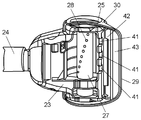
- FIG. 4 is a perspective view of the vacuum cleaner suction tool 20 according to the first embodiment and the second embodiment of the present invention as seen from below.
- FIG. 5 is a view of the internal configuration of the vacuum cleaner suction tool 20 according to the first embodiment of the present invention as viewed from above with the upper main body 22 removed.
- FIG. 6 is a side view of the vacuum cleaner suction tool 20 according to the first embodiment of the present invention.
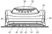
- FIG. 7 is a front view showing the vacuum cleaner suction tool 20 according to the first and third embodiments of the present invention.
- FIG. 1 is a perspective view of the vacuum cleaner suction tool 20 according to the first embodiment and the fourth embodiment of the present invention as viewed from above.
- FIG. 4 is a perspective view of the vacuum cleaner suction tool 20 according to the first embodiment and the second embodiment of the present invention as seen from below.
- FIG. 5 is a
- FIG. 8 is a cross-sectional view of the internal configuration of the vacuum cleaner suction tool 20 according to the first embodiment and the second embodiment of the present invention as viewed from the side.
- FIG. 9 is a side view showing a state in which the protrusion 29 of the auxiliary suction port 30 is inserted into the gap of the sofa 47 and used in the vacuum cleaner suction tool 20 shown in FIG. 3.
- the front of the vacuum cleaner suction tool 20 is a direction in which the intake port 41 (FIG. 4) is provided in the traveling direction of the vacuum cleaner suction tool 20 (FIG. 4). 6 shows the left side direction). Further, the rear of the vacuum cleaner suction tool 20 indicates the direction in which the connection pipe 24 is provided in the traveling direction of the vacuum cleaner suction tool 20 (the direction on the right side in FIG. 6).
- the vacuum cleaner suction tool 20 in the present embodiment includes a suction tool body 21, a suction chamber 25 (FIG. 4), and an auxiliary suction port body 30.
- the auxiliary suction port body 30 has a protruding portion 29 at the lower front portion of the auxiliary suction port body 30.
- a gap 31 (FIG. 6) as shown in FIG. 6 is provided between the front end portion of the bottom surface portion 48 (FIG. 6) of the protruding portion 29 and the surface to be cleaned.
- the suction tool main body 21 includes an upper main body portion 22 and a connection pipe 24.
- the connection pipe 24 is sandwiched between the lower main body portion 23 and the upper main body portion 22 and is provided so as to be rotatable up and down.
- the suction tool main body 21 is provided with a suction chamber 25, a turbine 26 (FIG. 5), and a rotating brush 27 (FIG. 5).
- the suction chamber 25 is provided in front of the suction tool main body 21.
- the suction chamber 25 has an opening below the suction tool main body 21. That is, the suction chamber 25 has a shape that opens downward.
- the suction chamber 25 (FIG. 4) is provided so as to communicate with the connection pipe 24.
- the connection pipe 24 is connected to the connection pipe 13 of the vacuum cleaner and the extension pipe 15.
- the turbine 26 is provided behind the suction tool main body 21.
- the rotating brush 27 is installed in the suction chamber 25 and is provided so as to rotate freely in conjunction with the turbine 26.
- Brush hairs 28 are provided on the outer periphery of the rotating brush 27.
- the brush hairs 28 are spirally implanted on the outer periphery of the rotating brush 27.
- the protruding portion 29 is provided at the lower front portion of the auxiliary suction port body 30.
- the shape of the protrusion 29 is formed such that the width in the height direction decreases from the rear to the front.
- the protrusion 29 has a tongue shape, that is, a shape that tapers from the rear to the front.
- the auxiliary suction port body 30 is provided on the outer shell of the suction tool body 21 as shown in FIG.
- the auxiliary suction port body 30 is provided in front of the suction tool main body 21.
- the gap 31 is a portion between the bottom surface portion 48 of the protruding portion 29 of the auxiliary suction port body 30 and the surface to be cleaned.
- the surface to be cleaned is a surface that is cleaned using a vacuum cleaner, such as a horizontal and flat floor.
- the bottom surface portion 48 is provided so that the gap 31 has a portion that widens from the rear to the front of the protruding portion 29.
- the inclined portion 32 is formed on the bottom surface portion 48 of the protruding portion 29.
- the inclination angle 33 indicates an angle formed by the inclined portion 32 and the surface to be cleaned.
- the inclination angle 33 is set in the range of 5 degrees to 50 degrees.
- the protruding portion 29 of the vacuum cleaner suction tool 20 configured as described above is inserted into a gap between the seat 47a such as the sofa 47 and the backrest 47b as shown in FIG.
- the dust collection airflow easily reaches the dust that has entered between the seat portion 47a and the backrest portion 47b.
- a dust collecting action is generated in the dust due to the dust collecting airflow. Thereby, dust can be collected efficiently.
- the bottom surface portion 48 of the vacuum cleaner suction tool 20 in the present embodiment has a width in the direction perpendicular to the surface to be cleaned of the protrusion 29 that decreases from the rear to the front of the protrusion 29. It has the part formed so that it may become.
- the width in the direction perpendicular to the surface to be cleaned of the protruding portion 29 indicates the width of the thickness in the height direction of the protruding portion 29 when viewed from the side.
- the width of the thickness of the tip portion of the protruding portion 29 is configured to have a portion that is thinner than the width on the connection pipe 24 side.
- the protruding portion 29 can be easily inserted into the gap between the seat 47a such as the sofa 47 and the backrest 47b. This is because the width of the thickness of the tip of the protrusion 29 is smaller than the width of the thickness on the side where the air inlet 41 (FIG. 4) is provided in the traveling direction of the protrusion 29.
- the gap between the seat 47a such as the sofa 47 and the backrest 47b increases. Thereby, it is possible to further easily collect dust accumulated in the back.
- the bottom surface 48 of the protrusion 29 of the vacuum cleaner suction tool 20 has a height in the direction perpendicular to the surface to be cleaned of the gap between the bottom surface 48 and the surface to be cleaned. What is necessary is just to form so that it may have a part formed so that it may become large toward back from the back.
- the protruding portion 29 can be pushed between the seat 47a such as the sofa 47 and the backrest 47b. Thereby, the clearance gap between the seat part 47a and the backrest part 47b can be expanded upwards. For this reason, a gap is more likely to occur in the bottom surface portion 48 of the protruding portion 29.
- This gap makes it easier for the dust collection airflow to reach the dust. Thereby, dust can be collected more efficiently.
- an inclined portion 32 is provided on the bottom surface portion 48 of the protruding portion 29.
- the height of the gap 31 indicates the height in the direction perpendicular to the surface to be cleaned between the bottom surface 48 of the protrusion 29 and the surface to be cleaned. That is, the height of the gap 31 indicates a distance in a direction perpendicular to the surface to be cleaned between a part of the protruding portion 29 and the surface to be cleaned.
- the gap 31 is provided so as to increase from the rear to the front of the protruding portion 29.
- the protrusion 29 configured in this manner is inserted between the seat 47a such as the sofa 47 and the backrest 47b when used. According to this, the space between the bottom surface portion 48 of the projecting portion 29 and the surface of the sofa 47 can be reliably ensured. For this reason, dust can be collected efficiently.
- the part formed so that it may become large toward the front from the back of the protrusion part 29 seems to have the inclined surface where the bottom face part 48 of the protrusion part 29 curves upwards with respect to a to-be-cleaned surface toward the front from back. May be provided.
- the turbine 26 is accommodated in the connection pipe 24.
- the turbine chamber 35 is configured by a space surrounded by the inside of the connection pipe 24 and the upper main body portion 22 and the lower main body portion 23.
- a turbine 26 As shown in FIG. 8, a turbine 26, a turbine shaft 36, and a turbine bearing (not shown) are provided in the turbine chamber 35.
- the turbine 26 is installed in the turbine chamber 35.
- the rotating brush 27 is driven by a turbine 26 that is a power source.
- the turbine shaft 36 is press-fitted and fixed at the rotation center of the turbine 26.
- the turbine shaft 36 is rotatably inserted into a turbine bearing (not shown).
- the small pulley 37 is provided on the opposite side of the turbine shaft 36 from the turbine 26.
- the turbine bearing is sandwiched between the upper main body 22 and the lower main body 23 in the turbine chamber 35.
- the outside air introduction port 38 is provided on the upper surface of the upper main body portion 22 so as to communicate with outside air.
- the outside air introduction port 38 is provided so that the front is opened.
- the ventilation channel 39 is provided between the upper main body 22 and the lower main body 23.
- the ventilation channel 39 is provided so as to communicate the outside air inlet 38 and the turbine chamber 35.
- the ventilation passage 39 takes in the inflow air that drives the turbine 26.
- the belt 40 is provided so as to stretch a small pulley 37 and a large pulley 34.
- the driving force of the turbine 26 is transmitted to the rotating brush 27 via the belt 40.
- suction air is generated.
- the suction air flows into the suction chamber 25 of the suction tool main body 21 through the connection pipe 24.
- a dust-absorbing wind that sucks dust is generated.
- driving air for driving the turbine 26 is generated from the outside air introduction port 38 via the ventilation passage 39 (FIG. 8).
- the rotating brush 27 is rotated by driving the turbine 26.
- the rotating brush 27 rotates via the belt 40. Thereby, the rotating brush 27 scoops up dust on the carpet or the like.
- the present invention is not limited to this, and the same effect as described above can be obtained also in the vacuum cleaner suction tool 20 in which the turbine 26 and the rotating brush 27 are not provided in the suction tool main body 21.
- the configuration in which the projecting portion 29 is provided so as to have a gentle slope from the rear to the front has been described.
- the present invention is not limited to this configuration.
- the bottom surface portion 48 of the projecting portion 29 may be provided so as to be partially inclined from the rear to the front. This is because the protrusion 29 can be inserted into the gap between the seat 47a such as the sofa 47 and the backrest 47b.
- the inclination angle 33 is set in the above-described range.
- the inclination angle 33 may be an angle at which the protruding portion 29 can be easily inserted into the gap between the seat portion 47a such as the sofa 47 and the backrest portion 47b.
- the vacuum cleaner suction tool 20 according to the second embodiment of the present invention basically has the same configuration as the vacuum cleaner floor suction tool according to the first embodiment.
- the suction tool main body 21 of the present embodiment includes an intake port 41 communicating with the suction chamber 25 at the lower front part.
- the space 42 is formed on the bottom surface 48 of the protrusion 29.
- a brush body 43 is provided on the bottom surface portion 48 of the protruding portion 29.
- the vacuum cleaner suction tool 20 includes a suction port 41 at the lower front portion of the suction tool body 21 as shown in FIG.
- the intake port 41 is provided so as to communicate with the suction chamber 25.
- the space portion 42 is provided on the bottom surface portion 48 (FIG. 6) of the protruding portion 29.
- the outside air sucked from the gap 31 (FIG. 6) between the bottom surface portion 48 (FIG. 6) of the protruding portion 29 and the surface to be cleaned is guided to the intake port 41 (FIG. 6).
- the vacuum cleaner suction tool 20 is provided at the lower front portion of the suction tool body 21 at the intake port 41 communicating with the suction chamber 25 and the bottom surface portion 48 of the protrusion 29.
- the space part 42 is provided. In the state where the suction tool main body 21 has the auxiliary suction port body 30, the space portion 42 allows outside air sucked from the gap 31 (FIG. 6) between the bottom surface portion 48 (FIG. 6) and the surface to be cleaned to the suction port 41. Shaped to guide.
- the strength of the dust collection airflow acting on the dust from the air inlet 41 can be made substantially uniform by the space portion 42. That is, if the dust is present inside the space portion 42, the dust collection airflow works substantially uniformly. For this reason, the dust collection airflow acts uniformly on the dust that has entered between the seat 47a such as the sofa 47 and the backrest 47b.
- the inlet 41 strongly guides the dust in the space 42 to the suction chamber 25. Due to the dust collecting action, dust can be collected efficiently.
- the vacuum cleaner suction tool 20 in the present embodiment is provided with a brush body 43 (FIG. 8) on the bottom surface portion 48 (FIG. 6) of the protruding portion 29.
- the brush body 43 is provided in front of the bottom surface portion 48 of the protruding portion 29 as shown in FIGS.
- the suction tool main body 21 is moved back and forth with the bottom surface 48 of the protruding portion 29 pressed against the surface to be cleaned.
- the brush body 43 for example, dust such as lint, hair, and pet animal hair entangled on the carpet that is the surface to be cleaned can be scraped and peeled off.
- the peeled thread or hairy dust flows into the space 42 provided on the bottom surface 48 of the protrusion 29. Dust is sucked into the suction chamber 25 through the air inlet 41. Thereby, dust can be collected efficiently.
- the vacuum cleaner suction tool 20 according to the third embodiment of the present invention basically has the same configuration as the vacuum cleaner floor suction tool according to the first embodiment.
- the auxiliary suction port body 30 of the third embodiment is detachably provided on the outer shell of the suction tool main body 21 by engaging / disengaging the locking portion 44 and the locked portion 45.
- a plurality of protrusions 46 are provided on the upper surface of the protrusion 29. At least a part of the surface layer portion of the protruding portion 29 is formed of a soft member.
- FIG. 10 is a perspective view showing the suction tool main body 21 of the vacuum cleaner suction tool 20 from above according to the third and fourth embodiments of the present invention.
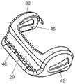
- FIG. 11 is a perspective view showing the auxiliary suction port body 30 of the vacuum cleaner suction tool 20 from above according to the third and fourth embodiments of the present invention.
- the suction tool main body 21 (FIG. 10) and the auxiliary suction port body 30 (FIG. 11) can be separated.
- the auxiliary suction port 30 is configured to be detachably attached to the outer shell of the suction tool main body 21.
- the auxiliary suction port 30 is detachably attached by engaging / disengaging the locking portion 44 and the locked portion 45.
- the vacuum cleaner suction tool 20 includes the locking portion 44 provided on the outer shell of the suction tool body 21 and the locked portion 45 provided on the auxiliary suction port body 30. I have. Further, the auxiliary suction port body 30 is detachably provided by engaging / disengaging the locking portion 44 and the locked portion 45.
- locking part 44 is each provided in the both sides
- the shape of the locking portion 44 has a substantially triangular triangular convex portion.
- the acute angle vertex of the convex part of the acute angle triangle is arranged in front of the suction tool main body 21 so that the acute angle vertex is located.
- the locked portion 45 has an opening having substantially the same shape.
- the auxiliary suction port body 30 is mounted from the front side of the suction tool body 21. At this time, the inclination of the two sides forming the acute angle of the triangle and the engaging portion 44 are fitted. That is, the opening which is the locked portion 45 is inserted into the acute triangular convex portion of the locking portion 44. With such a configuration, the auxiliary suction port body 30 (FIG. 11) is detachably attached to the outer shell of the suction tool body 21 (FIG. 10).
- the convex part of the acute triangle serves as a guide that makes it easy to fit the substantially identical opening.
- assistant suction inlet 30 and the suction tool main body 21 can be made easy to mount
- the suction tool main body 21 and the auxiliary suction port body 30 can be detachably separated. For this reason, it can be used separately according to each use of cleaning.
- auxiliary suction port body 30 when the auxiliary suction port body 30 is mounted, it can be used for dust that has entered a gap or entangled with a surface to be cleaned such as a carpet.
- auxiliary suction port 30 when the auxiliary suction port 30 is removed, it can be used as a standard cleaning application.
- the suction tool main body 21 and the auxiliary suction port body 30 are detachable.
- the auxiliary suction port 30 can be easily removed when it is unnecessary. Thereby, the effort which carries the suction tool with a different use separately can be saved.
- the vacuum cleaner suction tool 20 according to the fourth embodiment has basically the same configuration as the vacuum cleaner floor suction tool according to the first embodiment.
- a protrusion 46 is provided on the upper surface of the protrusion 29. Further, at least a part of the surface layer portion of the protruding portion 29 is formed of a soft member.
- a protrusion 46 is provided on the upper surface of the protrusion 29.
- a plurality of protrusions 46 are provided on the upper surface of the protrusion 29.
- This protrusion 46 makes it possible to easily remove the auxiliary suction port body 30 from the suction tool main body 21.
- the user first grounds the suction tool body 21 on the surface to be cleaned. And a user hold
- the user twists the extension tube 15 (FIG. 2) connected to the suction tool main body 21 sideways.
- locking part 44 (FIG. 10) remove
- the auxiliary suction port body 30 is detached from the suction tool main body 21.
- the protrusion 46 functions as an anti-slip when the user holds the auxiliary suction port body 30.
- the configuration in which a plurality of protrusions 46 are provided on the upper surface of the protrusion 29 has been described.
- the present invention is not limited to this configuration.
- one protrusion 46 may be provided on the upper surface of the protrusion 29. This is also because in this configuration, the auxiliary suction port body 30 can be easily detached from the suction tool body 21.
- At least a part of the surface layer portion of the protruding portion 29 is formed of a soft member.
- the surface layer portion of the protruding portion 29 indicates at least a part of the portion constituting the surface of the protruding portion 29.
- An example of the soft member is a resin.
- the protrusion 46 may be formed of a soft member.
- the protrusion part 46 can be used as an anti-slip
- the protrusion 46 has a high friction coefficient by using a soft member. Thereby, when removing the suction tool main body 21 from the auxiliary
- the vacuum cleaner suction tool 20 in the present embodiment includes a turbine 26 and a rotating brush 27.
- the turbine 26 is provided behind the suction tool main body 21 and rotates with the suction airflow.
- the rotating brush 27 is rotatably installed in the suction chamber 25 (FIG. 4) and rotates in conjunction with the turbine 26.
- the auxiliary suction port body 30 described above can suck dust that has entered the gap. That is, one suction tool can be used for a plurality of applications.
- the auxiliary suction port can suck dust that has entered the gap. Thereby, it can be used for several uses with one suction tool.
- the vacuum cleaner suction tool of the present invention it is possible to efficiently remove dust that has entered the gap and entangled with the surface to be cleaned such as a carpet.
- the present invention is useful for vacuum cleaner suction tools for electric appliances, industrial fields, and the like.
Abstract
Cette invention concerne un dispositif d'aspiration (20) pour aspirateur électrique, le dispositif comportant les éléments suivants : un corps de dispositif d'aspiration principal (21) ; une chambre d'aspiration raccordée au corps de dispositif d'aspiration principal (21) et dotée d'une ouverture située en bas du corps de dispositif d'aspiration principal (21) ; et un corps d'ouverture d'aspiration auxiliaire (30) entourant le corps de dispositif d'aspiration principal (21). Le corps d'ouverture d'aspiration auxiliaire (30) comporte une protubérance (29) située dans la partie avant inférieure dudit corps d'ouverture d'aspiration auxiliaire (30). Un espace vide (31) est prévu entre l'extrémité avant de la face inférieure (48) de la protubérance (29) et la surface à nettoyer.
Applications Claiming Priority (2)
| Application Number | Priority Date | Filing Date | Title |
|---|---|---|---|
| JP2011105969A JP2012235867A (ja) | 2011-05-11 | 2011-05-11 | 電気掃除機用吸込具 |
| JP2011-105969 | 2011-05-11 |
Publications (1)
| Publication Number | Publication Date |
|---|---|
| WO2012153460A1 true WO2012153460A1 (fr) | 2012-11-15 |
Family
ID=47138953
Family Applications (1)
| Application Number | Title | Priority Date | Filing Date |
|---|---|---|---|
| PCT/JP2012/002437 WO2012153460A1 (fr) | 2011-05-11 | 2012-04-06 | Dispositif d'aspiration pour aspirateur électrique |
Country Status (2)
| Country | Link |
|---|---|
| JP (1) | JP2012235867A (fr) |
| WO (1) | WO2012153460A1 (fr) |
Families Citing this family (4)
| Publication number | Priority date | Publication date | Assignee | Title |
|---|---|---|---|---|
| JP6174882B2 (ja) * | 2013-03-28 | 2017-08-02 | 株式会社コーワ | 床ノズル体 |
| KR102093133B1 (ko) * | 2019-02-11 | 2020-03-25 | 레이캅코리아 주식회사 | 청소기 헤드 |
| KR102093140B1 (ko) * | 2019-02-11 | 2020-03-25 | 레이캅코리아 주식회사 | 청소기 헤드 |
| KR102093144B1 (ko) * | 2019-02-11 | 2020-03-25 | 레이캅코리아 주식회사 | 청소기 헤드 |
Citations (2)
| Publication number | Priority date | Publication date | Assignee | Title |
|---|---|---|---|---|
| JPS63222721A (ja) * | 1987-02-05 | 1988-09-16 | デュプロ アクチエンゲゼルシャフト | 吸引式清掃機 |
| JPH0392121A (ja) * | 1989-09-06 | 1991-04-17 | Sanyo Electric Co Ltd | 掃除機用吸込具 |
-
2011
- 2011-05-11 JP JP2011105969A patent/JP2012235867A/ja not_active Withdrawn
-
2012
- 2012-04-06 WO PCT/JP2012/002437 patent/WO2012153460A1/fr active Application Filing
Patent Citations (2)
| Publication number | Priority date | Publication date | Assignee | Title |
|---|---|---|---|---|
| JPS63222721A (ja) * | 1987-02-05 | 1988-09-16 | デュプロ アクチエンゲゼルシャフト | 吸引式清掃機 |
| JPH0392121A (ja) * | 1989-09-06 | 1991-04-17 | Sanyo Electric Co Ltd | 掃除機用吸込具 |
Also Published As
| Publication number | Publication date |
|---|---|
| JP2012235867A (ja) | 2012-12-06 |
Similar Documents
| Publication | Publication Date | Title |
|---|---|---|
| US20230090575A1 (en) | Surface cleaning head with dual rotating agitators | |
| US8220109B2 (en) | Handheld pet hair vacuum cleaner | |
| US8261407B2 (en) | Vacuum cleaner accessory tool | |
| JP2010214112A (ja) | 表面処理用ヘッド | |
| JP3937405B2 (ja) | 電気掃除機用吸込み具及びこれを備えた電気掃除機 | |
| WO2012153460A1 (fr) | Dispositif d'aspiration pour aspirateur électrique | |
| US7051401B2 (en) | Suction nozzle for vacuum cleaner | |
| EP2934266A1 (fr) | Suceur passif d'aspirateur ayant une ouverture d'admission d'air | |
| JP2016000064A (ja) | 電気掃除機用吸込具およびそれを用いた電気掃除機 | |
| JP2010035604A (ja) | 掃除機用床ノズル及び電気掃除機 | |
| KR100761667B1 (ko) | 무배기 로봇 청소기 | |
| JP2017012688A (ja) | 吸込口体および電気掃除機 | |
| KR101054526B1 (ko) | 진공 청소기의 노즐 | |
| KR101055076B1 (ko) | 진공 청소기의 노즐 | |
| KR20100020644A (ko) | 청소기 브러시 | |
| JP2017012689A (ja) | 吸込口体および電気掃除機 | |
| KR101055066B1 (ko) | 진공 청소기의 노즐 | |
| JP2017023349A (ja) | 吸込口体および電気掃除機 | |
| AU2013237669B2 (en) | Handheld pet hair vacuum cleaner | |
| GB2468797A (en) | Handheld vacuum cleaner | |
| JP2017012686A (ja) | 吸込口体および電気掃除機 | |
| JP2010172563A (ja) | 吸込口体、電気掃除機 | |
| JP2012235859A (ja) | 掃除機用吸込具 |
Legal Events
| Date | Code | Title | Description |
|---|---|---|---|
| 121 | Ep: the epo has been informed by wipo that ep was designated in this application |
Ref document number: 12782252 Country of ref document: EP Kind code of ref document: A1 |
|
| NENP | Non-entry into the national phase |
Ref country code: DE |
|
| 122 | Ep: pct application non-entry in european phase |
Ref document number: 12782252 Country of ref document: EP Kind code of ref document: A1 |